

Members Mark Y0101xc Owner's Manual
Owner's Manual
!
Liquid Propane Gas Grill
MODEL Y0101XC
Customer Service Helpline: If you have questions about assembly or grill operation, or if there are damaged
or missing parts when you unpack this unit from the shipping box, call us 8am - 4:30 pm CST, Monday through
Friday at: 1-800-770-9769
WARNING:
Read this Owner's Manual carefully and be sure
your gas grill is properly assembled, installed and
maintained. Failure to follow these instructions
could result in serious bodily injury and/or property
damage. This gas grill is intended for outdoor use
only and is not intended to be installed in or on
recreational vehicles or boats.
Note to Installer: Leave this Owner's Manual
with the consumer after delivery and/or installation.
Note to Consumer: Leave this Owner's Manual
in a convenient place for future reference.
Manufacturer:
Grand Hall Enterprise Co., Ltd.
9th Fl., No.298, Rueiguang Rd., Neihu,
Taipei, Taiwan (114)
P4792E - Date: 04/01/2002
Table of Contents
Read These Safety Instructions
Warranty ..................................................... 2
Safety Instructions ..................................... 2
Pre-Assembly Instructions ......................... 4
Hardware, Parts Diagram and Lists ..... 5
Assembly Instructions ................................. 8
Lighting Instructions .................................. 15
Cleaning and Maintenance Instructions .... 17
Frequently Asked Questions .................. 19
Cooking Instructions ................................ 21
Cooking Guide and Recipes ................ 22
Member's Mark Grill Warranty
Full 1-Year Warranty
Ceramic Flame Tamers, Hose and Regulator,Caster
and Caster Seat, Control Knob (excludes paint
fading), Cast Aluminum Parts (paint fading), Grease
Receptacle(no rust through), Grease Draining Tray
(no rust through), Electronic Ignition(excluding
battery), Fuel Gauge(excluding batteries).
Full 2-Year Warranty
Cast iron burners(no rust through), Grill Bowl(no
rust through), Stainless Steel Cooking Grids,
Stainless Steel Grill Lid, Steel Cart
Warranty Service
Warranty service is available by contacting our
service center help line at 1-800-770-9769, Monday
through Friday, 8:00AM to 4:30PM CST.
Warranty Restrictions
This warranty is void if grill is used for commercial or rental purposes.
This grill is for use with Liquid Propane (LP)
to convert this grill to natural gas is dangerous
and will void your product warranty.
This warranty applies only when the grill is
used in the United States.
This warranty gives you specific legal rights,
and you may also have other rights which vary
from state to state. See page 20 for full details
of warranty.
FOR YOUR SAFETY
If you smell gas:
1. Shut off gas to the appliance.
2. Extinguish any open flame.
3. Open lid.
4. If odor continues, immediately call your
gas supplier or your fire department.
FOR YOUR SAFETY
1.
Do not store or use gasoline or other flammable vapors and liquids in the vicinity of this
or any other appliance.
An LP cylinder not connected for use shall not
2.
be stored in the vicinity of this or any other
appliance.
!
WARNING
Combustion byproducts produced when
using this product contain chemicals known
to the State of California to cause cancer,
birth defects, or other reproductive harm.
WARNING
!
Failure to comply with these instructions
could result in a fire or explosion that
could cause serious bodily injury, death,
or property damage.
!
WARNING
Your grill will get very hot. Never lean
over the cooking area while using your grill.
Do not touch cooking surfaces, grill housing,
grill lid or any other grill parts while the grill
is in operation, or until the grill has cooled
down after use.
Failure to comply with these instructions
may result in serious bodily injury.
Grill Installation Codes
This gas grill must be installed in accordance with
all local codes. In areas without local codes,
follow the latest edition of the National Fuel Gas
Code ANSI Z223.1. In Canada, installation must
conform to standard CAN/CGA 1b149.1 or 1-b149.
2 (Installation Code for Gas Burning Appliances
and Equipment) and all local codes.
Correct LP Gas Tank Use
LP gas grill models are designed for use with a
standard 20 lb. Liquid Propane Gas (LP gas)
tank, not included with grill box. Never connect
your gas grill to an LP gas tank that exceeds
this capacity. A tank of approximately 12 inches
in diameter by 18-1/2 inches high is the maximum size LP gas tank to use. We recommend
buying an "OPD" gas tank which offers an Overfill
Prevention Device. This safety feature prevents the
tank from being overfilled which can cause malfunction of the LP gas tank, regulator and/or grill.
The LP gas tank must be constructed and
marked in accordance with specifications of the U.
S. Dept. of Transportation (DOT). In Canada, the
LP gas tank must meet the Canadian Transportation and Communications (CTC) specifications.
Also be sure to read and follow all LP instructions on the following page.
2
1.
The LP gas tank has a shutoff valve, terminating in an LP gas supply tank valve outlet,
that is compatible with a Type 1 tank connection device. The LP gas tank must also
have a safety relief device that has a direct
communication with the vapor space of the
tank.
The tank supply system must be arranged
2.
for vapor withdrawal.
The LP gas tank used must have a collar
3.
to protect the tank valve.
Proper Placement and Clearance of Grill
Never use your gas grill in a garage, porch, shed,
breezeway or any other enclosed area. Your gas grill is
to be used outdoors only, at least 24 inches from the
back and side of any combustible surface. Your
gas grill should not be placed under any surface
that will burn. Do not obstruct the flow of ventilation
air around the gas grill housing.
This outdoor gas grill is not intended to be installed in
or on recreational vehicles and/or boats.
WARNING!
Failure to comply with these instructions
could result in a fire or explosion that
could cause serious bodily injury, death,
or property damage.
Never connect an unregulated LP gas tank to
your gas grill. The gas regulator assembly
supplied with your gas grill is adjusted to have
an outlet pressure of 11" water column (W.C.)
for connection to an LP gas tank.
Only use the regulator and hose assembly
supplied with your gas grill. Replacement
regulators and hose assemblies must be those
specified by manufacture.
Have your LP gas tank filled by a reputable
propane gas dealer and visually inspected and
re-qualified at each filling.
Never fill the gas tank beyond 80% full.
Have your propane gas dealer check the
release valve after every filling to ensure that it
remains free of defects.
Always keep LP gas tanks in an upright
position.
Do not store (or use) gasoline or other flammable
vapors and liquids in the vicinity of this gas grill.
An LP gas tank that is not connected for use must
NOT be stored on bottom shelf or in the vicinity of
this or any other gas grill.
Do not subject the LP gas tank to excessive heat.
Never store an LP gas tank indoors. If you
store your gas grill in the garage or other indoor
location, always disconnect the LP gas tank
first and store it safely outside.
LP gas tanks must be stored outdoors in a
well-ventilated area. Disconnected LP gas tanks
must not be stored in a building, garage or
any other enclosed area.
When your gas grill is not in use the gas
must be turned off at the LP gas tank.
The regulator and hose assembly must be
inspected before each use of the grill. If there
is excessive abrasion or wear or if the hose
is cut, it must be replaced prior to the grill
being used again.
Keep the gas regulator hose away from hot
grill surfaces and dripping grease. Avoid
unnecessary twisting of hose. Visually inspect
hose prior to each use for cuts, cracks,
excessive wear or other damage. If the hose
appears damaged do not use the gas grill.
Call our service center at 1-800-770-9769.
Never light your gas grill with the lid closed
or before checking to insure the burner tubes
are fully seated over the gas valve orifices.
Never allow children to operate your grill. Do
not allow children to play near your grill.
!
WARNING
A strong gas smell, or the hissing sound of
gas indicates a serious problem with your
gas grill or the LP gas tank. Failure to
immediately follow the steps listed below
could result in a fire or explosion that could
cause serious bodily injury, death, or property damage.
Shut off gas supply to the gas grill.
Turn the control knobs to OFF position.
Put out any flame with a fire extinguisher.
Open grill lid.
Get away from the LP gas tank.
Do not try to fix the problem yourself.
If odor continues or you have a fire you cannot
extinguish, call your fire department.
Do not call near the LP gas tank because your
telephone is an electrical device and could
create a spark resulting in fire and/or explosion.
NOTE: The normal flow of gas through the
regulator and hose assembly can create a
humming noise. A low volume of noise is
perfectly normal and will not interfere with
operation of the grill. If humming noise is
loud and excessive you may need to purge
air from the gas line or reset the regulator
excess gas flow device. This purging procedure should be done every time a new LP
gas tank is connected to your grill. For help
call the Customer Service Helpline for
assistance.
Customer Service Helpline, 8:00am-4:30pm
CST, Monday through Friday at: 1-800-7709769
3
CAUTION: BEWARE OF FLASH-BACK
Pre-Assembly Instructions
CAUTION: Spiders and small insects occasionally spin webs or make nests in the grill
burner tubes during transit and warehousing.
These webs can lead to a gas flow obstruction which could result in a fire in and around
the burner tubes. This type of fire is known
as a "FLASH-BACK" and can cause serious
damage to your grill and create an unsafe
operating condition for the user.
Although an obstructed burner tube is not the
only cause of "FLASH-BACK", it is the most
common cause.
To reduce the chance of "FLASH-BACK", you
must clean the burner tubes before assembling your grill, and at least once a month in
late summer or early fall when spiders are
most active. Also perform this burner tube
cleaning procedure if your grill has not been
used for an extended period of time.
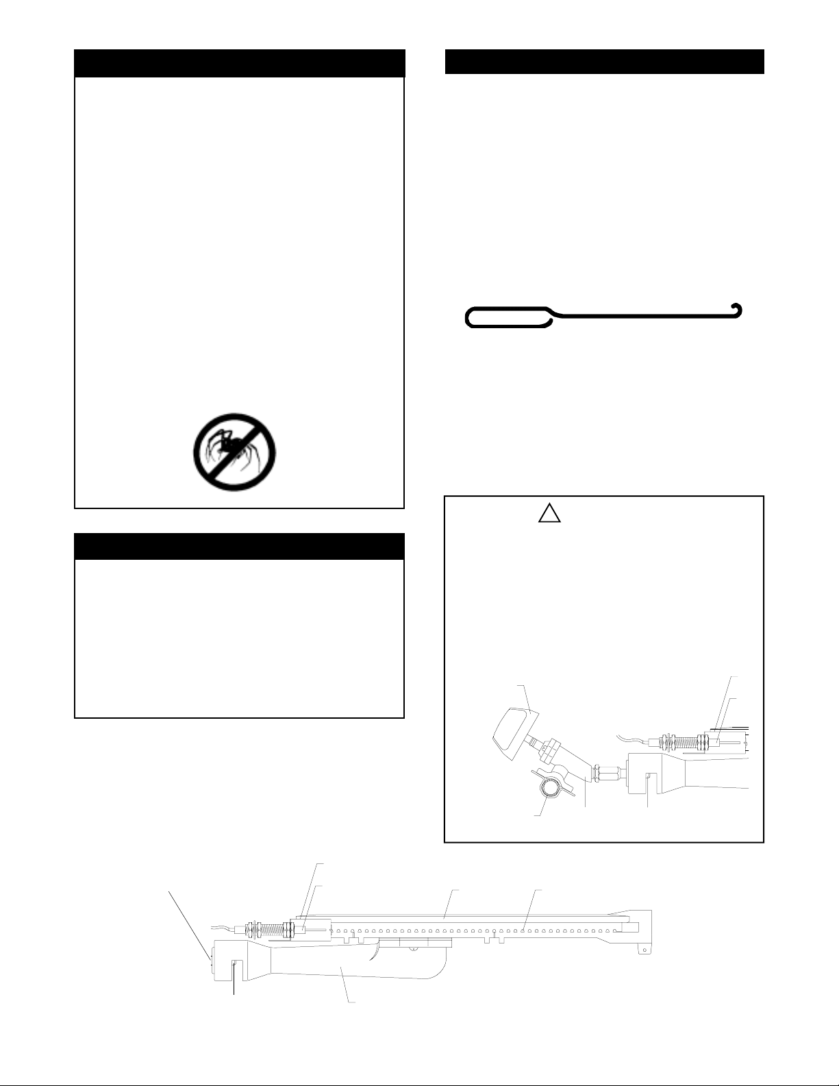
To reduce the chance of "FLASH-BACK" (see
CAUTION at left) clean the burner tubes and
burners before fully assembling your grill. Remove the cotter pin from the rear underside of
each burner using a pair of long nose pliers.
Carefully lift each burner up and away from the
gas valve orifice, then refer to ILL. 1 and perform one of these three cleaning methods:
Bend a stiff wire, (a lightweight coat hanger
1.
works well) into a small hook as shown
below. Run the hook through the burner tube
and inside the burner several times to remove
any debris.
Use a bottle brush with a flexible handle.
2.
Run the brush through the burner tube and
inside the burner several times, removing any
debris.
Use an air hose to force air through each
3.
burner tube. The forced air should pass
debris or obstructions through the burner and
out the ports.
Tools Required for Assembly
Phillips head screw driver
Adjustable wrench
Long nose pliers - used to remove cotter pin
when cleaning the burners
Open-end wrench, included, - used to tighten
castors and side burner control panel.
Protective work gloves
Eye protection
ILL. 1
To Clean Burner Tube,
Insert Hook Here
Gas Collector Box
Spark Electrode
!
WARNING
The location of the burner tube with respect
to the orifice is vital for safe operation.
Check to ensure the orifice is inside of the
burner tube before using your gas grill. See
ILL. 2. If the burner tube does not fit over
the valve orifice, lighting the burner may
cause explosion and/or fire.
ILL. 2
Control
Knob
Section of
Manifold
Burner
Gas Valve
Burner Port
Orifice
Orifice
Burner Tube
4
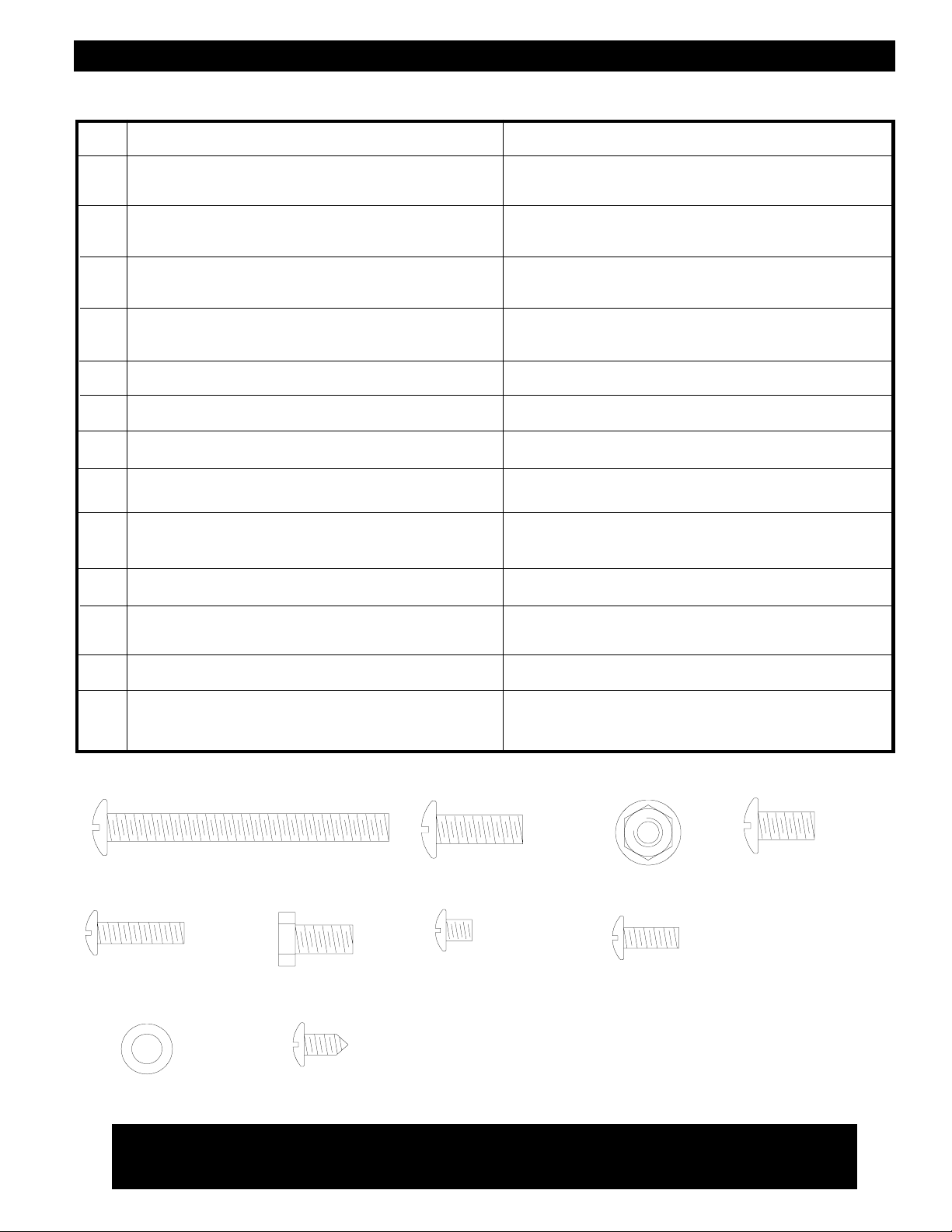
Contents for Hardware Pack (PART# P55J4A)
Contents for Hardware Pack (Part #P4182A)
Contents for Hardware Pack (Part #P4182A)
The following table illustrates a breakdown of the screwpack. It highlights what components are
used in the various stages of assembly.
REF.
B.
N.
L.
E.
E.
G.
E.
C.
Q.
K.
E.
COMPONENTS USES
1/4" x 2 1/2" PHILLIPS HEAD SCREW
X8
X4
1/4" x 3/4" PHILLIPS HEAD SCREW
X4
1/4" LOCK NUT
X2
1/4" x 1/2" PHILLIPS HEAD SCREW
X4
1/4" x 1/2" PHILLIPS HEAD SCREW
X4
3/16" x 3/4" PHILLIPS HEAD SCREW
1/4" x 1/2" PHILLIPS HEAD SCREW
X2
1/4" x 1/2" HEX. HEAD SCREW
X8
M5 x 6mm PHILLIPS HEAD SCREW
X4
(ALREADY SCREWED INTO DOOR HANDLES)
3/16" x 1/2" PHILLIPS HEAD SCREW
X2
1/4" x 1/2" PHILLIPS HEAD SCREW
X2
ASSEMBLES 2 BOTTOM SHELF BRACKETS TO
THE CART LEGS
SECURES GRILL BOWL ONTO THE CART
ATTACHES TANK GAUGE TO SIDE PANEL
ATTACHES TANK HOOK AND TANK HOLDER TO
TANK GAUGE
SECURES REAR PANEL TO THE CART
ATTACHES DOOR BRACKET TO THE CART
ATTACHES SHELF BRACKET TO CART LEG
INSTALLS THE HANDLES ONTO THE DOORS
SECURES REAR WIND SHIELD TO THE BACK OF
GRILL CART.
INSTALLS THE SPICE TRAY TO SIDE SHELF
C.
T.
U.
E.
B. 1/4" x 2 1/2" PHILLIPS HEAD SCREW x 8
G. 3/16" x 3/4" PHILLIPS
HEAD SCREW x 4
1/4" x 1/2" HEX HEAD SCREW
X2
PLAIN WASHER
X2
X1
M4 x 10 SELF-TAPPING SCREW
X4
1/4" x 1/2" PHILLIPS HEAD SCREW
C.1/4" x 1/2" HEX
HEAD SCREW X 10
INSTALLS THE CONTROL PANEL TO SIDE BURNER
INSTALLS THE LIGHTING STICK TO SIDE PANEL
SECURES SIDE SHELF AND SIDE BURNER TO
SHELF BRACKETS
Actual Sizes:
N. 1/4" x 3/4" PHILLIPS
HEAD SCREW x 4
(found in door handles)
Q. M5 x 6mm PHILLIPS
HEAD SCREW x 4
L. 1/4" LOCK
NUT x 4
K. 3/16" x 1/2" PHILLIPS
HEAD SCREW x 2
E. 1/4" x 1/2" PHILLIPS
HEAD SCREW x 14
T. PLAIN WASHER x 2
U. M4 x 10 SELF-
TAPPING SCREW x 1
Customer Service Helpline: If you have questions about assembly or grill operation, or if there are damaged
or missing parts when you unpack this unit from the shipping box, call us 8am - 4:30 pm CST, Monday through
Friday at: 1-800-770-9769
5
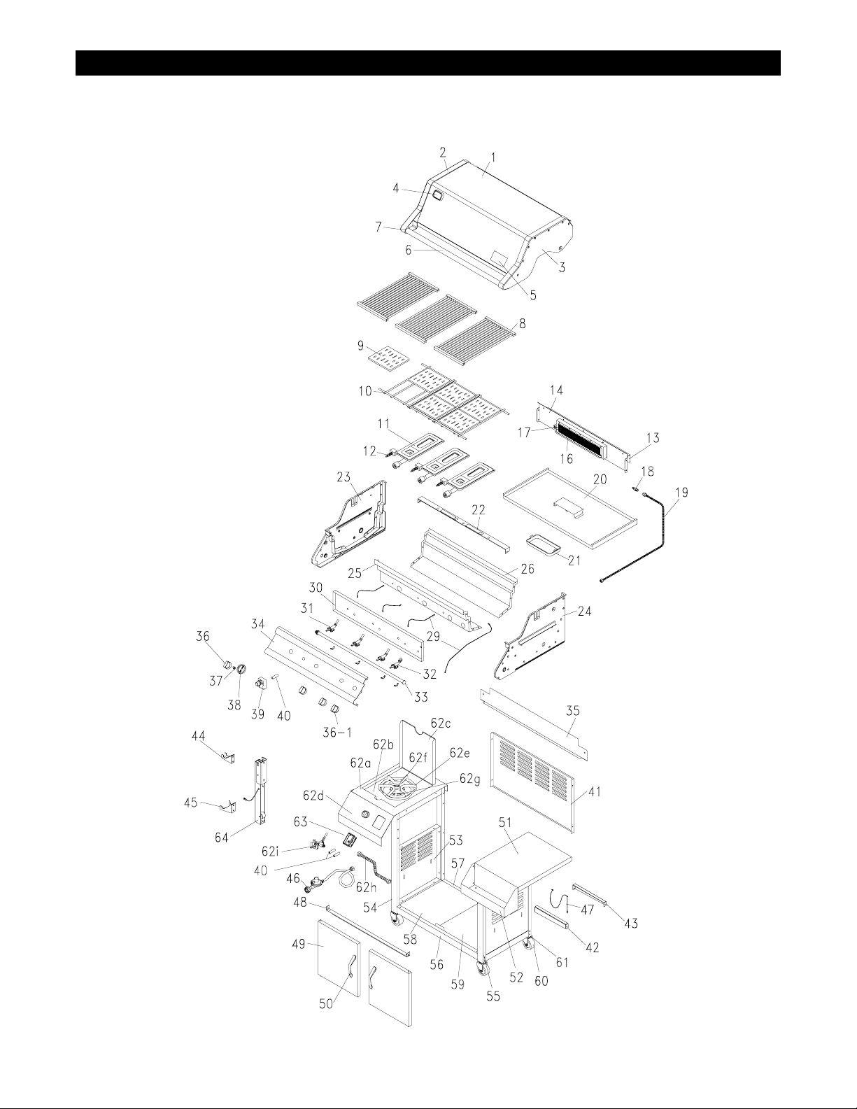
Y0101XC Parts Diagram
Remove all components from cartons and place within easy reach. Turn the largest carton
upside down and it will provide a comfortable height work surface for grill assembly.
6

Y0101XC Parts List
QTY.REF# PART#DESCRIPTION
QTY.REF# PART#DESCRIPTION
10.
11.
12.
13.
14.
16.
17.
18.
19.
20.
21.
22.
23.
24.
25.
26.
29.
30.
31.
32.
33.
34.
35.
36.
36-1.
37.
38.
39.
40.
41.
42.
43.
44.
45.
46.
47.
48.
49.
50.
51.
52.
53.
54.
55.
Lid Plate
1.
Lid Side Panel, left
2.
Lid Side Panel, right
3.
Heat Indicator
4.
Name Plate
5.
Lid Handle
6.
Heat-Insulating Spacer
7.
Cooking Grid
8.
Ceramic Flame Tamer
9.
Rack for Flame Tamer
Burner
Gas Collector Box W. Electrode
Cover for Back Burner
Frame for Back Burner
Back Burner
Spark Electrode
Orifice
Gas Tube Assembly
Grease Draining Tray
Grease Receptacle
Burner Bracket
Bowl Side Panel, left
Bowl Side Panel, right
Bowl Front Panel
Bowl Rear Panel
Electric Wire Set
Heat Shield for Control Panel
Gas Valve for Main Burner
Gas Valve for Back Burner
Gas Manifold
Control Panel
Rear Wind Shield
Control Knob
Control Knob(Back Burner)
Spring
Control Knob Seat
Electric Ignitor
AA Battery
Rear Panel
Shelf Bracket-A
Shelf Bracket-B
Tank Hook
Tank Holder
Regulator W. Hose
Lighting Stick
Door Bracket
Door Plate
Door Handle
Side Shelf
Spice Tray
Side Panel
Cart Legs, left
Cart Legs, right
P0162B
P0155B
P0156B
P0618A
P0435C
P0234A
P5573A
P1650A
P1736A
P1736B
P1925A
P2623B
P8085B
P80F1A
P1947A
P2515A
P5643A
P3512A
P2738B
P2717A
P2219A
P0753B
P0754B
P0733A
P0734A
P2634A
P2943B
P3229Z
P32A9C
P5029A
P2964B
P8089C
P3431D
P3431E
P80E3A
P3430C
P2503E
P8080A
P4317D
P1216A
P1216B
P4041A
P4042A
P3632N
P5540A
P4407F
P4337A
P0247A
P1169A
P5212B
P4318C
P0842C
P0842D
1
1
1
1
1
1
2
3
6
1
3
3
1
1
1
1
1
1
1
1
1
1
1
1
1
1
1
3
1
1
1
1
4
1
5
5
1
3
1
2
2
1
1
1
1
1
2
2
1
1
2
1
1
Bottom Shelf Bracket, front
56.
Bottom Shelf Bracket, rear
57.
Bottom Shelf, left
58.
Bottom Shelf, right
59.
Castor
60.
Castor Seat
61.
Side Burner Frame
62a.
Side Burner Body
62b.
Side Burner Lid
62c.
Side Burner Control Panel
62d.
Pot Support
62e.
Side Burner
62f.
Spark Electrode for Side Burner
62g.
Connection Tube
62h.
Gas Valve for Side Burner
62i.
Tank gauge display
63.
Tank gauge
64.
Owner's Manual
Hardware Pack (content page5)
CSA label located here
For the repair or replacement parts you need:
Call 8:00am - 4:30 pm CST, Monday through Friday
at 1-800-770-9769
To make sure you obtain the correct replacement part
(s) for your Member's Mark Gas Grill, please refer
to the parts list on this page. The following information
is required to assure getting the correct part:
1. Gas Model Number (see CSA label on grill)
2. Part Number
3. Description
4. Quantity of parts needed
Please allow sufficient time to process and ship.
IMPORTANT: Keep this Owner's Manual for convenitent
referral and for part replacement.
IMPORTANT: Use only factory authorized parts. The
use of any part that is not factory authorized can
be dangerous. This will also void your warranty.
P1034S
P1034T
P1034U
P1034V
P5115B
P4524A
P1168A
P2327A
P1144A
P2963B
P80E4B
P1922A
P2632B
P39A5A
P32B3A
P80N4A
P80N5A
P4792E
P55J4A
1
1
1
1
4
4
1
1
1
1
1
1
1
1
1
1
1
1
1
Customer Service Helpline: If you have questions about assembly or grill operation, or if there are damaged
or missing parts when you unpack this unit from the shipping box, call us 8am - 4:30 pm CST, Monday through
Friday at: 1-800-770-9769
7
Assembly Instructions
Remove all cart parts, hardware, and grill head from shipping box. Raise the grill lid and remove all packed
components. Use the parts list on page 5, 6, and 7 to check that all necessary parts have been included.
Assemble the gas grill on a protective work surface to avoid scratching grill surfaces. Inspect your grill for
damage as you proceed. Do not assemble or operate your grill if it appears damaged. If there are damaged
or missing parts when you unpack the shipping box, or you have questions during the assembly process, call
8:00am - 4:30pm CST, Monday through Friday at: 1-800-770-9769.
While it is possible for an individual to assemble this gas grill, we recommend asking for the assistance of
another person when maneuvering some of the larger or heavier pieces. You may need both Adjustable Wrench
and Phillips Screw Driver (not provided) for securing the nuts and scews.
1.
2.
HINT:
3.
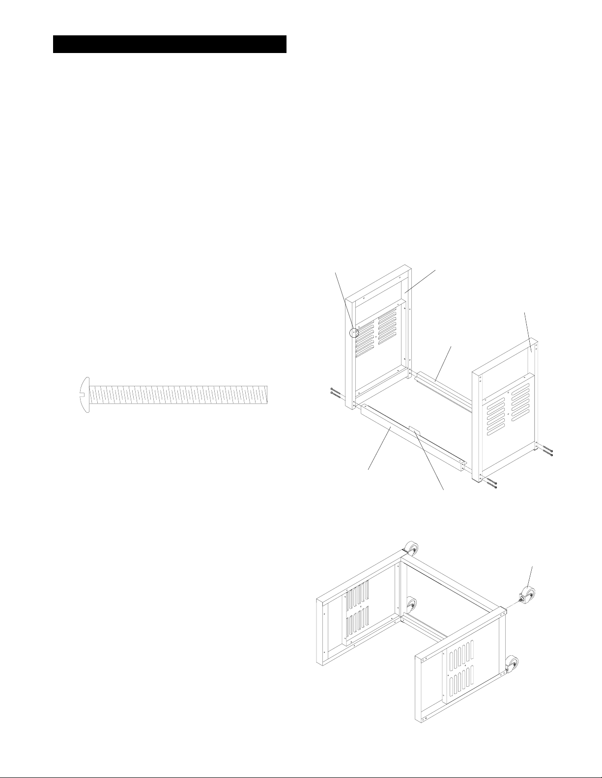
Assembling The Cart
Before installing the bottom shelf brackets, make
sure: A) the ledges of both bottom shelf brackets
face each other B) the bottom shelf bracket equipped
with door stop must be located in the front C) the
side of Cart Legs having a threaded hole for Door
Bracket must face inwards. Refer to ILL. 1.
Install the bottom shelf brackets between cart legs.
Align the threaded holes on the ends of bottom shelf
bracket with the holes on cart legs. Screw loosely
using 8 of the "B" 1/4" x 2-1/2" phillips head screws.
B. 1/4" x 2 1/2" PHILLIPS HEAD SCREW x 8
Insert the screw through the Cart Leg, then
match the screw end with the threaded hole on
the Bottom Shelf Bracket.
Secure each Caster to the bottom of the Cart Leg
by turning the threaded caster stem clockwise until
full stop. Fasten firmly using the Customized Wrench.
(included in hardware pack) See ILL. 2.
ILL. 1
THREADED HOLE FOR
DOOR BRACKET
BOTTOM SHELF
BRACKET, front(P1034S)
ILL. 2
CART LEGS
LEFT(P0842C)
CART LEGS
RIGHT(P0842D)
BOTTOM SHELF
BRACKET, rear(P1034T)
DOOR STOP
CASTER
(P5115B)
8
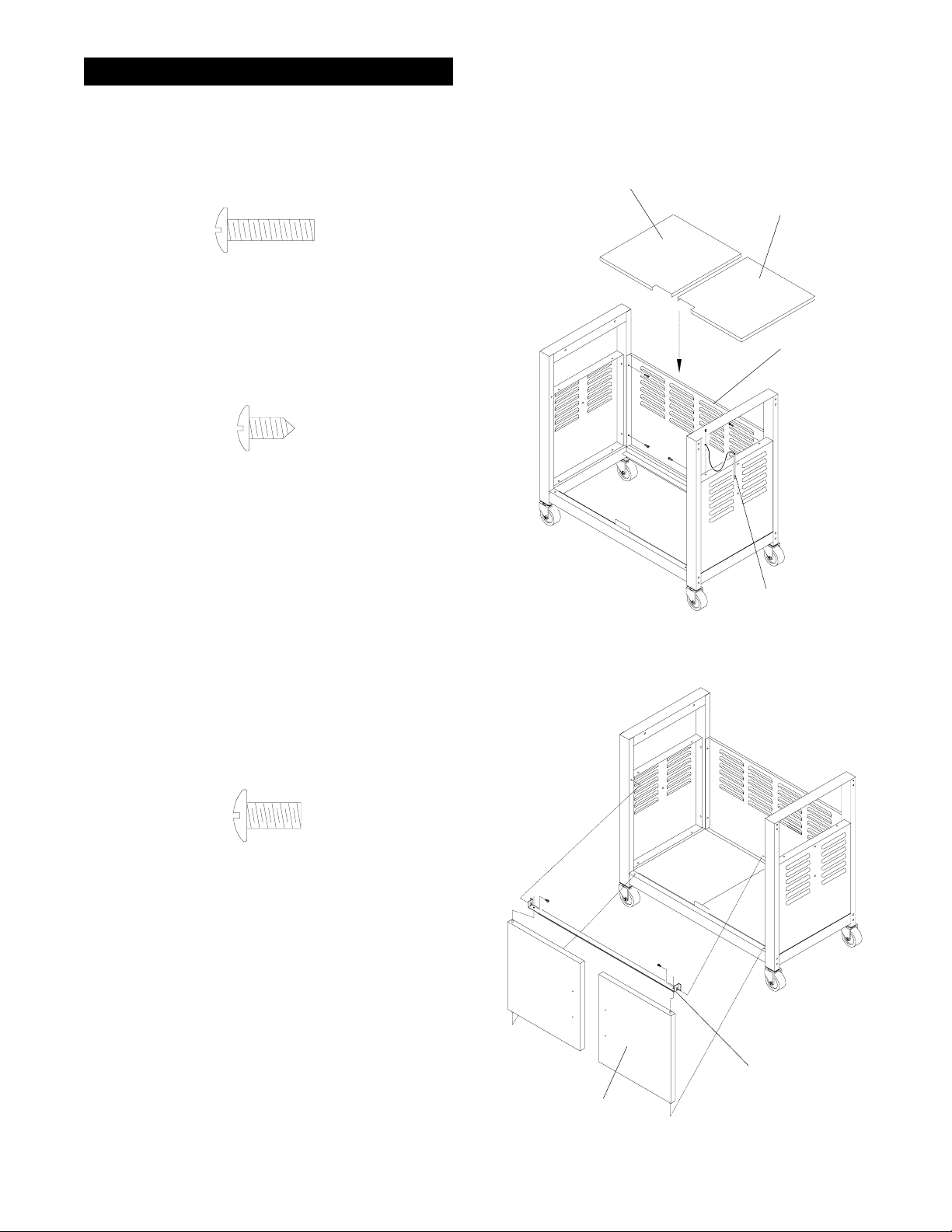
Assembly Instructions
Attach the rear panel to the cart legs as shown
4.
in ILL. 3. Align the holes on panel with the holes
on cart legs. Screwing loosely 4 of the "G" 3/16"
x 3/4" phillips head screws provided.
G.3/16" x 3/4" PHILLIPS HEAD SCREW x 4
5.
Secure the Lighting Stick to the top of the right
side panel. Fix firmly by using 1 of the "U" M4
x 10 self-tapping screw packed with Lighting Stick.
U.M4 x 10 SELF-TAPPING
SCREW x 1
ILL. 3
BOTTOM SHELF, left
(P1034U)
BOTTOM SHELF, right
(P1034V)
REAR PANEL
(P4317D)
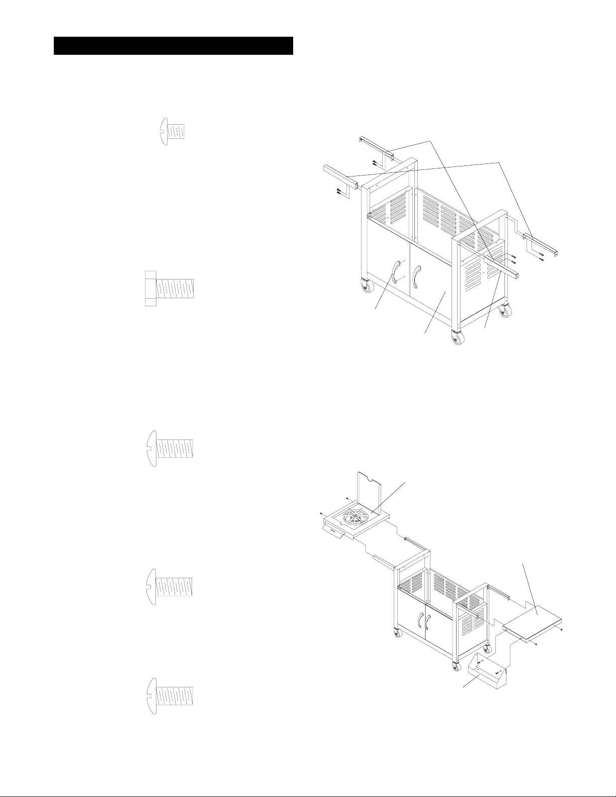
6.
Place the 2 bottom shelves over the ledges of both
bottom shelf brackets.
7.
Attach the Door Brackets to cart legs.Be sure the
folded strip of the bracket is closest to the cart
legs. Then align the holes on both ends of the
bracket with the threaded holes on the cart legs.
Fix the Door Bracket by screwing 2 of the "E"
1/4"x 1/2" phillips head screws loosely. Refer to
ILL. 4.
E.1/4" x 1/2" PHILLIPS
HEAD SCREW x 2
8.
Locate the hinge holes for the door on the Bottom
Shelf Bracket. Insert the door hinges into these holes
and holes on Door Bracket. Push the Door Bracket
down to an even level and then screw it firmly using
a screw driver. See ILL4.
LIGHTING
STICK
(P5540A)
ILL. 4
DOOR
BRACKET
DOOR
(P4337A)
(P4407F)
9
Assembly Instructions
Install the door handles onto the door plates with
9.
4 of the "Q" M5 x 6mm phillips head screws
provided. See ILL 5.
(found in door handles)
Q.M5 x 6mm PHILLIPS
HEAD SCREW x 4
10.
Attach the Shelf Brackets to cart legs. Align the
holes on the Bracket to the holes at upper section
of each legs.Be sure the decoration panel of Shelf
Brackets faces outward. Secure firmly using 8 of
the "C" 1/4"x1/2" Hex. head screws. See ILL 5.
C.1/4"x1/2" HEX. HEAD
SCREW x 8
11.
Attach Stainless steel Side Shelf to the right side
of the Cart. Put the Side Shelf on the Shelf
Brackets. Align the holes on the Side Shelf with
the threaded holes at the end of Shelf Brackets.
Fix firmly by using 2 of the "E" 1/4"x1/2" Phillips
head screws. See ILL. 6.
ILL. 5
DOOR HANDLE
(P0247A)
SHELF BRACKET-A
(P1216A)
DOOR
(P4337A)
SHELF BRACKET-B
(P1216B)
DECORATION
PANEL
E.
1/4" x 1/2" PHILLIPS
HEAD SCREW x 2
Place Side Burner on to the Shelf Brackets on
12.
the left. Align the holes on the Side Shelf with
the threaded holes at the end of Shelf Bracket.
Fix firmly by using 2 of the "E" 1/4" x 1/2" Phillips
head screw.
E.1/4" x 1/2" PHILLIPS
HEAD SCREW x 2
13.
Install Spice Tray with 2 of the "E" 1/4"x1/2"
Phillips head screws.
E.1/4" x 1/2" PHILLIPS
HEAD SCREW x 2
ILL. 6
SIDE BURNER
SIDE SHELF
(P1169A)
SPICE TRAY
(P5212B)
10
 Loading...