

Members Mark Monarch04alp, Monarch04ang Owner's Manual

safety, thoroughly inspect every nut and bolt and
secure as necessary before using your new grill.
Important Note: This grill is manufactured to
exact specifications. Model MONARCH04ALP is
certified for use with LP gas and Model
MONARCH04ANG is certified for use with Natural
Gas. You can not convert this grill from one fuel
type to the other. For your safety, conversion kits
are not available. Any attempt to convert your grill will
void your warranty.
Liquid Propane Gas Grill
MODEL MONARCH04ALP
Natural Gas Grill
MODEL MONARCH04ANG
Owner's Manual
Manufacturer:
Grand Hall Enterprise Co., Ltd.
9th Fl., No.298, Rueiguang Rd., Neihu,
Taipei, Taiwan (114)
WARNING:
Read this Owner's Manual carefully and be sure your
gas grill has been properly assembled, installed and
maintained. Failure to follow these instructions could
result in serious bodily injury and/or property damage.
This gas grill is intended for outdoor use only and is
not intended to be installed in or on recreational
vehicles or boats.
Note to Installer: Leave this Owner's Manual
with the consumer after delivery and/or installation.
Note to Consumer: Leave this Owner's Manual in
a convenient place for future reference. Nuts and Bolts
may become loose during transit, so for your own
P80109001F - Rev: 2004/04/22
!
Grill Information Center: If you have questions about assembly or grill operation, or if there are damaged
or missing parts when you unpack this unit from the shipping box, do not return this product to the store,
call us 8:00am - 4:30 pm CST, Monday through Friday at 1-800-770-9769

2
Warranty..........................................................2
Safety Instructions......................................2-4
Instructions Before Using Your Grill..........5
Parts Diagram and Lists............................6
Assembly Instructions....................................11
Lighting Instructions........................................15
Back Burner, Rotisserie Instructions.........18
Cleaning and Maintenance Instructions.........22
Frequently Asked Questions.......................24
Cooking Instructions...................................A-1
Cooking Guide............................................A-2
Read These Safety Instructions
Your grill will get very hot. Never lean
over the cooking area while using your grill.
Do not touch cooking surfaces, grill housing,
grill lid or any other grill parts while the grill
is in operation, or until the grill has cooled
down after use.
Failure to comply with these instructions
may result in serious bodily injury.
Member's Mark Grill Warranty
Warranty Restrictions:
• This warranty does not cover surface rust or
natural oxidation.
• This warranty is void if grill is used for
commercial or rental purposes.
• This warranty applies only when the grill is used
in the United States.
• This warranty gives you specific legal rights,
andyou may also have other rights which vary
fromstate to state. See back cover for warranty
details.
Full 1-Year Warranty on Grill
For one year from the date of purchase, the Manufacturer
will replace any grill part (except rusting or AA batteries)
that is defective in material or workmanship.
Limited Warranty on Selected Grill Parts
From the date of purchase for the designated time
periods stated below, the Manufacturer will replace the
following grill parts if they are defective in material or
workmanship. You will be charged shipping and handling.
This warranty does not cover labor charges.
• Lifetime of the grill: Stainless steel parts
(except for discoloration due to normal use or
excessive heat, and scratches or dents caused
by normal use and improper maintenance).
• 2 Years: Cast-iron Burners
• For Warranty Service: Call our Grill Information
Center 8am - 4:30pm CST, Monday through
Friday at 1-800-770-9769
Table of Contents
Do not store or use gasoline or other flammable vapors and liquids in the vicinity of this
or any other appliance.
An LP gas tank not connected for use shall
not be stored in the vicinity of this or any other
appliance.
1.
2.
FOR YOUR SAFETY
Combustion by products produced when
using this product contain chemicals known
to the State of California to cause cancer,
birth defects, or other reproductive harm.
Failure to comply with these instructions
could result in a fire or explosion that
could cause serious bodily injury, death,
or property damage.
WARNING
!
WARNING
!
WARNING
!
Shut off gas to the appliance.
Extinguish any open flame.
Open lid.
If odor continues, immediately call your
gas supplier or your fire department.
FOR YOUR SAFETY
If you smell gas:
Correct LP Gas Tank Use
LP gas grill models are designed for use with a
standard 20 lb. Liquid Propane Gas (LP gas) tank,
not included with grill box. Never connect your gas
grill to an LP gas tank that exceeds this capacity.
A tank of approximately 12 inches in diameter by
18-1/2 inches high is the maximum size LP gas
tank to use. You must use an "OPD" gas tank
which offers a listed Overfill Prevention
Device. This safety feature prevents the tank from
being overfilled which can cause malfunction of the
LP gas tank, Regulator and/or grill.
The LP gas tank must be constructed and marked
in accordance with specifications of the U.S. Dept.
of Transportation (DOT). In Canada, the LP gas
tank must meet the Canadian Transportation and
Communications (CTC) specifications. Also be sure
to read and follow all LP instructions on the
following page.
Grill Installation Codes
The installation must conform with local codes or,
in the absence of local codes, with either the
National Fuel Gas Code, ANSI Z223.1/NFPA 54,
or CAN/CGA-B149.1, Natural Gas and Propane
Installation Code.
(a) Do not store a spare LP-gas cylinder
under or near this appliance;
(b) Never fill the cylinder beyond 80
percent full; and
(c) If the information in "(a)" and "(b)" is
not followed exactly, a fire causing
death or serious injury may occur.
WARNING
!
1.
2.
3.
4.
Never connect an unregulated LP gas tank to
your gas grill. The gas Regulator assembly
supplied with your gas grill is adjusted to have
an outlet pressure of 11" water column (W.C.)
for connection to an LP gas tank.
Only use the Regulator and Hose Assembly
supplied with your gas grill. Replacement
Regulators and Hose Assemblies must be
those specified by manufacturer.
Have your LP gas tank filled by a reputable
propane gas dealer; visually inspected and requalified at each filling.
Never fill the gas tank beyond 80% full.
Have your propane gas dealer check the
release valve after every filling to ensure that it
remains free of defects.
Always keep LP gas tanks in an upright
position.
Do not store (or use) gasoline or other flammable
vapors and liquids in the vicinity of this gas grill.
An LP gas tank that is not connected for use must
NOT be stored inside cabinet or in the vicinity of
this or any other gas grill.
Do not subject the LP gas tank to excessive heat.
Never store an LP gas tank indoors. If you
store your gas grill in the garage or other indoor
location, always disconnect the LP gas tank
first and store it safely outside.
When your gas grill is not in use the gas
must be turned off at the LP gas tank.
•
•
•
•
•
•
•
•
•
•
•
Proper Placement and Clearance of Grill
Never use your gas grill in a garage, porch, shed,
breezeway or any other enclosed area. Your gas grill is
to be used outdoors only, at least 24 inches from the
back and side of any combustible surface. Do not
locate this appliance under overhead unprotected
combustible surfaces. Do not obstruct the flow of
ventilation air around the gas grill housing.
This outdoor gas grill is not intended to be installed in
or on recreational vehicles and/or boats.
The LP gas tank has a Shut Off Valve,
terminating in an LP gas supply tank valve
outlet, that is compatible with a Type 1 tank
connection device. The LP gas tank must
also have a safety relief device that has a
direct communication with the vapor space of
the tank.
The tank supply system must be arranged
for vapor withdrawal.
The LP gas tank used must have a collar
to protect the tank valve.
1.
2.
3.
Failure to comply with these instructions
could result in a fire or explosion that
could cause serious bodily injury, death,
or property damage.
WARNING
3
The Regulator and Hose Assembly can be
seen after opening the doors (if applicable),
and must be inspected before each use of the
grill. If there is excess abrasion or wear or if
the hose is cut, it must be replaced prior to
the grill being used again.
Keep the gas Regulator Hose away from hot
grill surfaces and dripping grease. Avoid
unnecessary twisting of hose. Visually inspect
the Regulator and Hose prior to each use for
cuts, cracks, excessive wear or other damage.
If the Hose appears damaged do not use the
gas grill. Call our Grill Information Center for a
replacement, at 1-800-770-9769.
Never light your gas grill with the Lid closed
or before checking to ensure the Burner Tubes
are fully seated over the gas valve orifices.
Never allow children to operate your grill. Do
not allow children to play near your grill.
LP gas tanks must be stored outdoors in a
well-ventilated area and out of the reach of
children. Disconnected LP gas tanks must not
be stored in a building, garage or any other
enclosed area.
•
•
•
•
•
!
WARNING
NOTE: The normal flow of gas through the
Regulator and Hose Assembly can create a
humming sound. A low volume of sound is
perfectly normal and will not interfere with
operation of the grill. If humming sound is
loud and excessive you may need to purge
air from the gas line or reset the Regulator
excess gas flow device. This purging procedure should be done every time a new LP
gas tank is connected to your grill. For help
call the Grill Information Center for
assistance.
Grill Information Center:
8:00am - 4:30pm CST,
Monday through Friday at: 1-800-770-9769
Shut off gas supply to the gas grill.
Turn the Control Knobs to OFF position.
Extinguish any open flam such as candle, cigarette,
lighter, etc., that could cause gas to ignite.
Open the Grill Lid.
Get away from the LP gas tank.
Do not try to fix the problem yourself.
If odor continues or you have a fire you cannot
extinguish, call your fire department. Do not call
near the LP gas tank because your telephone is an
electrical device and could create a spark resulting
in fire and/or explosion.
•
•
•
•
•
•
•
!
If you smell gas:

4
• Your Natural Gas Grill is designed to operate on
Natural Gas only, at a pressure of 7" water column
(W.C.) (1/4 psi or 1.75 kpa), regulated at the
residential meter. Check with your gas utility
company for local gas pressure and with your local
municipality for building code requirements. If your
residential gas line pressure has not been
regulated to 7" W.C., contact your local gas
utilitycompany for professional assistance.
• The gas pressure Regulator supplied with this
appliance must be used. This Regulator is
set for an outlet pressure of 4" W.C.
• It is recommended that a Shut Off Valve be installed
at the gas supply source outdoors. Install at a point
after the gas pipe exits the outside wall and before the
Quick Disconnect Hose, or install it at the point
before the gas line piping enters the ground. See
Figure 1.
• Pipe sealing compound or pipe thread tape resistant
to the action of Natural Gas must be used on all male
pipe threads when making the connection.
• Disconnect your gas grill from fuel source when
the gas supply is being tested at high pressures.
This gas grill and its individual Shut Off Valve must
be disconnected from the gas supply pipe system
during any pressure testing of that system at
pressure in excess of 1/2 psi (3.5kpa).
• Turn off your gas grill when the gas supply is
tested at low pressures. The grill must be isolated
from the gas supply pipe system by closing its
individual Manual Shut Off Valve during any
pressure testing of the gas supply pipe system at
pressures equal to or less than 1/2 psi (3.5kpa).
• The Quick Disconnect connects to a 3/8 inch NPT
thread from gas source. The Quick Disconnect
fitting is a hand operated device that automatically
shuts off the the flow of gas from the source when
it is disconnected.
• The Quick Disconnect fitting can be installed
horizontally, or pointing downward. DO NOT install
the fitting with the opening pointing upward
because the fitting could collect water and debris.
• The Dust Covers (plastic plugs) provided with the
Quick Disconnect help keep the open ends
clean while disconnected.
• The outdoor connector must be firmly attached to
a ridged permanent construction.
• The Quick Disconnect MUST BE installed above
ground.
• WARNING: Do not route the 12 foot Quick
Disconnect Hose under a deck. The hose must be
visible and inspected prior to each grill use.
Figure 1
(For Natural Gas Model Only)
If the length of line required does not exceed 50 feet,
use a 5/8" O.D. tube. One size larger should be used
for lengths greater than 50 feet.
Gas piping may be copper tubing, type K or L;
polyethylene plastic tube, with a minimum wall
thickness of .062 inch; or standard weight (schedule
40) steel or wrought iron pipe.
Copper tubing must be tin-lined if the gas contains
more than 0.3 grams of hydrogen sulfide per 100
cubic feet of gas.
Plastic tubing is suitable only for outdoor, underground use.
Gas piping in contact with earth, or any other material which may corrode the piping, must be protected
against corrosion in an approved manner.
Underground piping must have a minimum of 18"
cover.
All connections and joints must be thoroughly tested
for leaks in accordance with local codes and all listed
procedures in the latest edition of ANSI Z223.1
Gas Line Piping
Test Connections
NATURAL GAS SUPPLY
QUICK
DISCONNECT
I
N
S
I
D
E
W
A
L
L
O
U
T
S
I
D
E
W
A
L
L
MALE
FITTING
TO NATURAL GAS
REGULATOR
LOCKING GAS
SHUT OFF VALVE
LOCKING
GAS
SHUT OFF
VALVE
Additional
Hardware Not
Included
Natural Gas Safety Instructions
Do not use an open flame to check for
gas leaks. Be sure there are no sparks
or open flames in the area while you
check for gas leaks. This will result in a
fire or explosion which can cause serious
bodily injury or death, and damage to
property.
DANGER
!

To reduce the chance of "FLASH-BACK" (see
CAUTION at left) clean the Burner Tubes and
Burners before fully assembling your grill. Remove the Cotter Pin from the rear underside of
each Burner using a pair of long nose pliers.
Carefully lift each Burner up and away from the
Gas Valve Orifice, then refer to Figure 1 and
perform one of these three cleaning methods:
Before Using Your Grill
3.
Bend a stiff wire, (a lightweight coat hanger
works well) into a small hook as shown
below. Run the hook through the Burner Tube
and inside the Burner several times to remove
any debris.
Use a bottle brush with a flexible handle. Run
the brush through the burner tube and inside
the burner several times, removing any debris.
Use an air hose to force air through each
Burner Tube. The forced air should pass
debris or obstructions through the Burner and
out the ports.
1.
2.
Figure 2
The location of the Burner Tube with respect
to the Orifice is vital for safe operation.
Check to ensure the Orifice is inside the
Burner Tube before using your gas grill. See
Figure 2. If the Orifice is not inside the
Burner Tube, lighting the Burner may cause
explosion and/or fire.
WARNING
GAS VALVE ASSEMBLY
ORIFICE
BURNER TUBE
Figure 1
GAS COLLECTOR BOX
TO CLEAN BURNER TUBE
INSERT HOOK HERE
SPARK ELECTRODE
BURNER
FOOT
COTTER PIN
BURNER PORT
GAS COLLECTOR BOX
SPARK ELECTRODE
!
Assembly Instructions For Your Safety
During unpacking, assembly and construction
stages always wear work gloves and eye
protection.
As you unpack this gas grill from shipping
box, use the parts list to ensure all necessary parts are included. Inspect all parts for
damage as you proceed. Do not operate
your grill if it appears demage. If you have
questions during the assembly process, call
8am - 4:30pm CST, Monday through Friday,
1-800-770-9769
CAUTION:
While it is possible for one person to
unpack this gas grill, obtain assistance from
another person when handing the large and
heavy grill head.
CAUTION: Spiders and small insects occasionally spin webs or make nests in the
grill Burner Tubes during transit and
warehousing. These webs can lead to a gas
flow obstruction which could result in a fire
in and around the Burner Tubes. This type
of fire is known as a "FLASH-BACK" and
can cause serious damage to your grill and
create an unsafe operating condition for the
user.
Although an obstructed Burner Tube is not
the only cause of "FLASH-BACK", it is the
most common cause.
To reduce the chance of "FLASH-BACK",
you must clean the Burner Tubes before
assembling your grill, and at least once a
month in late summer or early fall when
spiders are most active. Also perform this
Burner Tube cleaning procedure if your grill
has not been used for an extended period
of time.
CAUTION: BEWARE OF FLASH-BACK
BURNER TUBE
5

Phillips Head Screw 1/4"x1/2"
Qty. 8
Ref.# S112G04081
Flange Nut 1/4"
Qty. 2
Ref.# S313G04061
The following table illustrates a breakdown of the hardware pack. It highlights what components are used
in the various stages of assembly.
Contents for Hardware Pack / LPG (Part #P06002001A)
6
Grill Information Center: If you have questions about assembly or grill operation, or
if there are damaged or missing parts when you unpack this unit from the shipping box, call us
8:00 am - 4:30 pm CST, Monday through Friday at: 1-800-770-9769
Actual Size and Quantity of Each Hardware Piece:
Battery/AA
Qty. 2
Ref. # P05301001A
Phillips Head Screw 1/4"x1/2"
Qty. 8
Ref.# S112G04081
Flange Nut 1/4"
Qty. 2
Ref.# S313G04061
Battery/AAA
Qty. 2
Ref. # P05301002A
The following table illustrates a breakdown of the hardware pack. It highlights what components are used
in the various stages of assembly.
Contents for Hardware Pack / NG (Part #P06002005A)
Actual Size and Quantity of Each Hardware Piece:
Battery/AA
Qty. 2
Ref. # P05301001A
S112G04081
S313G04061
P05301001A
8
2
2
Phillips Head Screw 1/4"x1/2"
Flange Nut 1/4"
Battery/AA
Attaches Side Shelves To Grill
Attaches Side Shelves To Grill
Powers The Electric Igniter
Ref.
Purpose of Components
Qty.Component
Attaches Side Shelves To Grill
Attaches Side Shelves To Grill
Powers The Electric Igniter
Powers The Tank Fuel Gauge Display
8
2
2
2
S112G04081
S313G04061
P05301001A
P05301002A
Phillips Head Screw 1/4"x1/2"
Flange Nut 1/4"
Battery/AA
Battery/AAA
Ref.
Purpose of Components
Qty.Component

7
MONARCH04ALP & NG Parts Diagram

MONARCH04ALP & NG Parts List
REF#
PART#
DESCRIPTION
QTY
Lid Assembly
Protective Pad
Lid Handle
Lid Handle Bracket, Left
Lid Handle Bracket, Right
Lid Handle Heat-Insulating Spacer
Temperature Gauge
Control Panel
LPG
NG
Control Knob w. Rubber Ring for Main & Side Burner
Control Knob w. Rubber Ring for Back & Smoker Burner
Control Knob Seat
Lid Hinge with Nut
Bowl Side Panel/Trim Plate/Left
Bowl Side Panel/Trim Plate/Right
Flame Tamer / Ceramic
Flame Tamer / Rack
Cooking Grid - Large
Cooking Grid - Small
Cooking Rack/Secondary
Grease Tray Heat Shield
Grease Tray
Grease Tray Slide
Burner/Main
Burner Air Shutter/Main (NG only)
Burner Bracket
Gas Collector Box with Electrode
Smoker Burner
Smoker Drawer Bracket
Smoker Drawer
Gas Valve/Manifold Assembly
LPG
NG
Extension Tube for Manifold
Cart Bracket for Gas Fittings
Extension Tube Fitting
Electric Wire Set
Electric Ignitor, 4-port
Electric Ignitor, 2-port
Back Burner Assembly
LPG
NG
Back Burner Wind Shield
Side Burner Lid
Side Burner Pot Support
Side Burner Body
Side Burner with Brass Ring
LPG
NG
Side Burner Air Shutter (LPG only)
Side Burner Electrode
Side Shelf
Side Shelf Bracket, Left
Side Shelf Bracket, Right
Side Shelf Lock
Door Bracket
Cart Support
Cart Bottom Shelf
Cart Rear Panel (LPG only)
Cart Rear Panel (NG only)
Hose/NG/Protective Ring
Cart Side Panel, Left
Cart Side Panel, Right
Door Handle
Door Stop/2 PCS
Y0110019
P05518002I
P00205005B
P00301016E
P00302016E
P06801002A
P00601171A
P02911011P
P02911011Q
P03411053L
P03411063L
P03415014A
P05511006A
P07514015A
P07514016A
P01804001A
P01722021B
P01604001B
P01604002B
P01516001B
P06904001C
P02713013C
P05516046A
P02001044E
P05524105A
P02203034A
P02609001B
P02008025A
P06708001A
P06701002A
Y0060085
Y0060086
P03715002A
P03324001C
P03907002A
P02615006A
P02502134C
P02502062C
Y0030012
Y0030013
P06906002C
P00115026A
P00815002D
P02301001B
P02002001A
P02002004A
P05524003A
P02607001C
P01105030B
P01209001A
P01210001A
P05501003A
P03301008K
P03301009K
P01010003C
P07701009A
P07701010A
P05328001A
P07602001A
P07603001A
P00214028H
P05517016E
1.
2.
3.
4.
5.
6.
7.
8.
9.
10.
11.
12.
13.
14.
15.
16.
17.
18.
19.
20.
21.
22.
23.
23a.
24.
25.
26.
27.
28.
29.
30.
31.
32.
33.
34.
35.
36.
37.
38.
39.
40.
41.
41a.
42.
43.
44.
45.
46.
47.
48.
49.
50.
51.
51a.
52.
53.
54.
55.
1
2
1
1
1
2
1
1
1
4
2
6
2
1
1
6
1
2
1
1
1
1
2
3
3
1
4
1
1
1
1
1
1
1
1
1
1
1
1
1
1
1
1
1
1
1
1
1
2
1
1
4
1
2
1
1
1
1
1
1
3
3
8
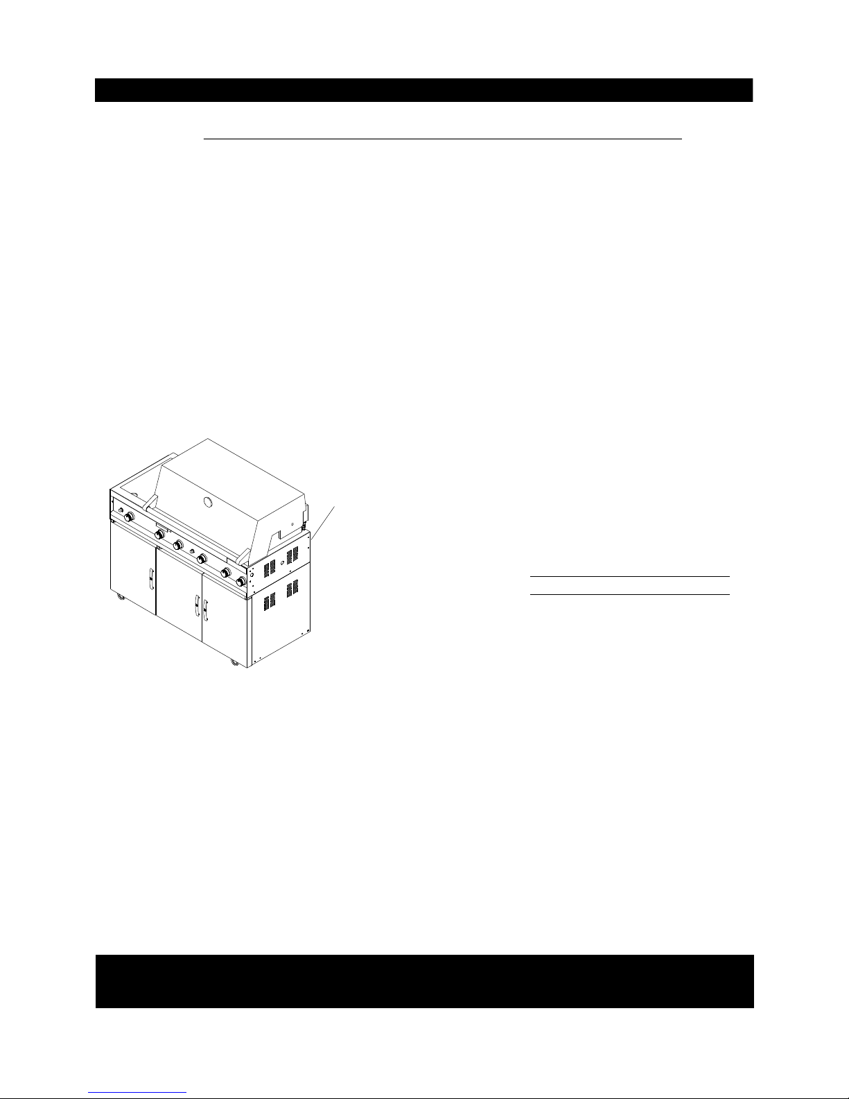
Record your grill Model Number and Serial Number
below for future reference.
MODEL NUMBER
SERIAL NUMBER
CSA label located
here
MONARCH04ALP & NG Parts List
REF#PART#DESCRIPTION
QTY
For the repair or replacement parts you need:
Call 8:00am - 4:30 pm CST, Monday through Friday at 1-800-770-9769
To make sure you obtain the correct replacement part(s) for your Member's Mark Gas Grill, please refer to
the parts list on this page. The following information is required to assure getting the correct part(s):
1. Model and Serial Number (see CSA label on grill)
2. Part Number
3. Description
4. Quantity of part(s) needed
Please allow sufficient time to process and ship
IMPORTANT: Keep this Owner's Manual for convenient referral and for part(s) replacement.
IMPORTANT: Use only factory authorized parts. The use of any part that is not factory authorized can be
dangerous. This will also void your warranty.
Grill Information Center: If you have questions about assembly or grill operation, or
if there are damaged or missing parts when you unpack this unit from the shipping box, call us
8:00 am - 4:30 pm CST, Monday through Friday at: 1-800-770-9769
9
Door
Door Trim Plate
Door Hinge Bracket, Left Top
Door Hinge Bracket, Right Top
Door Hinge Bracket, Left Bottom
Door Hinge Bracket, Right Bottom
Cart Shelf/Wire
Lighting Stick
Tank pull-out Tray / Fuel Gauge Display Assembly (LPG only)
Caster, 3 in., w. Brake
Caster Seat, Left Front & Right Rear
Caster Seat, Right Front & Left Rear
Regulator w. Hose/LPG
Regulator Assembly/NG
Hose, 12ft./NG
Back Burner Extension Tube
Hardware Pack (LPG only)
Hardware Pack (NG only)
Rotisserie Assembly
Owner’ s Manual
Grill Cover
P04301016A
P07510001E
P03314035C
P03314036C
P03314037C
P03314038C
P05204003F
P05313023B
Y0340011
P05110005E
P05327001E
P05327002E
P03601011A
Y0080014
P03703001A
P03701010A
P06002001A
P06002005A
Y0250048
P80109001F
P07007003A
3
3
2
1
2
1
1
1
1
4
2
2
1
1
1
1
1
1
1
1
1
56.
57.
58.
59.
60.
61.
62.
63.
64.
65.
66.
67.
68.
69.
70.
71.
----
----
----
----
----

Y0250048 Rotisserie Assembly Parts Diagram
Y0250048 Rotisserie Assembly Parts List
10
Grill Information Center: If you have questions about assembly or grill operation, or
if there are damaged or missing parts when you unpack this unit from the shipping box, call us
8:00 am - 4:30 pm CST, Monday through Friday at: 1-800-770-9769
REF#
PART#
DESCRIPTION
QTY
1
2
3
4
5
6
7
8
9
10
Rot. Spit
Rot. Holding Fork
Rot. Thumbscrew 3/8"x1/2"
Rot. Collar
Rot. Bushing
Rot. Handle
Rot. Motor Bracket
Rot. Motor/AC #PTP2000
Rot. Phillips Head Screw 3/16"x1/2" UNF
Rot. Plain Washer 3/16"
1
2
3
1
1
1
1
1
2
2
P05508085F
P05508082F
S196G06084
P05508083F
P05508080F
P05508076E
P03308002A
P07101016B
S112G03084
S411G03064
Hardware for Rotisserie
Rot. Phillips Head Screw 3/16"x1/2"UNF
Qty. 2
Ref. #S112G03084
Rot. Plain Washer 3/16"
Qty. 2
Ref. #S411G03064
Rot. Thumbscrew 3/8"x1/2"
Qty. 3
Ref. #S196G06084
 Loading...