

Members Mark Mg3208slp Owner's Manual

Manual # P80109065L - Date:2008/01/14
OPERATOR'S MANUAL
Liquid Propane Gas (LPG)
Grill
Model MG3208SLP
NOTE TO ASSEMBLER / INSTALLER:
Leave this manual with the consumer.
NOTE TO CONSUMER:
Keep this manual for future reference.
RECORD YOUR SERIAL # __________________
(see silver CSA label on main body of grill)
Ÿ
Ÿ
IMPORTANT:
Ÿ
FREE HELP
FROM THE GRILL EXPERTS
Do not return to the store. At Grand Hall we're
the experts on this product and trained to help
you with:
Assembly questions
Grill operation
Replacement of damaged or missing parts
Ÿ
Ÿ
Ÿ
visit www.grandhall.com or call:
1-800-770-9769
Monday - Friday 8:00am-4:30pm CST
Failure to comply with these instructions could
result in a fire or explosion that could cause
serious bodily injury, death or property damage.
Whether this grill was assembled by you or
someone else, you must read this entire manual
before using your grill to ensure the grill is
properly assembled, installed and maintained.
Use your grill at least 3 feet away from any
wall or surface. Use your grill at least 3 feet
away from combustible objects that can melt or
catch fire such as vinyl or wood siding, fences
and overhangs or sources of ignition including
pilot lights on water heaters and live electrical
appliances.
THIS GAS APPLIANCE IS DESIGNED FOR OUTDOOR USE ONLY.
Never use your gas grill in a garage, porch,
shed, breezeway or any other enclosed area.
Never obstruct the flow of ventilation air
around your gas grill housing.
Never disconnect the gas regulator or any gas
fitting while your grill is lit. A lit grill can ignite
leaking gas and cause a fire or explosion which
could result in property damage, personal injury
or death.
Ÿ
Ÿ
Ÿ
Ÿ
Ÿ
Ÿ
WARNING
! !
Ÿ

2
Table of Contents
Primary Safety Warnings...........................1-3
Pre-Assembly Instructions..............................3
Part Diagrams and Lists........................4-10
Assembly Instructions.............................11-16
Use & Care Instructions:
• Gas Safety and Leak Tests...........17-19
• Lighting Instructions............................20-21
• Troubleshooting..........................................21
• Rotisserie Instruction...........................22-24
• Cleaning and Maintenance................25-26
• Cooking Guide...................................A1-A3
• Frequently Asked Questions............A4-A5
Warranty Terms...........................Back Cover
WARNING
! !
•
Keep gas regulator hose away from hot grill
surfaces and dripping grease. Avoid unnecessary twisting of hose. Visually inspect hose
prior to each use for cuts, cracks, excessive
wear or other damage. If the hose appears
damaged do not use the gas grill. Call Grand
Hall at 1-800-770-9769 for a certified replacement hose.
California Proposition 65
Combustion byproducts produced when using
this product contain chemicals known to the
State of California to cause cancer, birth defects, or other reproductive harm.
Brass components on the grill, such as hose
fittings, propane cylinder valves (sold separately) and burner valve stems, contain lead
which is known to the State of California to
cause cancer, birth defects, or other reproductive harm.
Never use charcoal or lighter fluid in this gas
grill. Failure to comply with these instructions
could result in a grease fire or explosion that
could cause serious bodily injury, death or
property damage.
The Grease Draining Tray and Grease Receptacle must be visually inspected before each
grill use. Remove any grease and wash Grease
Draining Tray and Grease Receptacle with a
mild soap and warm water solution. Failure to
comply with these instructions could result in a grease fire or explosion that could
cause serious bodily injury, death or property damage.
LPG models must be used with Liquid
Propane Gas and the regulator assembly
supplied. Natural Gas models must be used
with Natural Gas only. Any attempt to convert
the grill from one fuel type to another is
hazardous and must be performed by a
qualified gas technician only, using a NG
Conversion Kit purchased from Grand Hall.
•
•
•
•
Keep any electrical supply cord and the fuel
supply hose away from any heated surface.
WARNING
! !
DANGER
!
!
1.
2
3.
4.
If you smell gas:
Shut off gas to the appliance.
Extinguish any open flame.
Open lid.
If odor continues, keep away from
the appliance and immediately call
your gas supplier or your fire
department.
Do not store or use gasoline or
other flammable liquids or vapors in
the vicinity of this or any other
appliances.
An LP cylinder not connected for
use shall not be stored in the vicinity of this or any other appliance.
1.
2.
WARNING
! !

Pre-Assembly Instructions For Your Safety
Grill Installation Codes
The installation must conform with local codes or, in the
absence of local codes, with either the National Fuel
Gas Code, ANSI Z223.1/NFPA 54, Natural Gas and
Propane Installation Code, CSA B149.1, or Propane
Storage and Handling Code, B149.2.
3
Spiders and small insects can spin webs and
nest in the grill Burner Tubes during transit and
warehousing which can lead to a gas flow
obstruction resulting in a fire in and around the
Burner Tubes. This type of "FLASHBACK FIRE"
can cause serious grill damage and create an
unsafe operating condition for the user.
To reduce the chance of FLASHBACK
FIRE you must clean the Burner Tubes
as follows before assembling your grill.
Also do this at least once a month in summer
and fall or whenever spiders are active in your
area, and if your grill has not been used for an
extended period of time.
Failure to comply with these instructions could
result in a fire or explosion that could cause
serious bodily injury, death or property damage.
TO CLEAN BURNER
TUBE, INSERT HOOK
HERE
1.
2.
3.
4.
WARNING
! !
METHOD 1: Bend a stiff wire or wire coat
hanger into a small hook as shown and run
the hook through the Burner Tube and inside
the Burner several times to remove debris.
METHOD 2: Use a bottle brush with a flexible
handle and run the brush through the Burner
Tube and inside the Burner several times to
remove any debris.
METHOD 3: Use an air hose to force air
through each Burner Tube. The forced air
should pass debris or obstructions through
the Burner and out the Ports.
Remove the screw from the rear of each Burner
using a Phillips Head Screwdriver.
Carefully lift each Burner up and away from the
Gas Valve Orifice.
Check and clean Burner/Venturi Tubes for
insects and insect nests. A clogged tube can
lead to a fire beneath the grill.
Refer to the figure below and perform one of
these 3 cleaning methods:
Orifice Burner Tube
Gas Valve Assembly
For safe operation ensure the Gas Valve Assembly
Orifice is inside the Burner Tube before using your
grill. See figure. If the Orifice is not inside the Burner
Tube, lighting the Burner may cause explosion
and/or fire resulting in serious bodily injury and/or
property damage.
9
Burner
Tools Required for Assembly:
protective work gloves
protective eyewear
While it is possible for one person to unpack this gas
grill, obtain assistance from another person when
handling the large pieces.
Use the Hardware and Part Diagrams to ensure all
items are included and free of damage.
Do not assemble or operate the grill if it appears
damaged. If there are damaged or missing parts
when you unpack the shipping box or you have
questions during the assembly process, call the:
To expedite the assembly process follow these
general guidelines:
•
•
Grill Information Center 1-800-770-9769
8am-4:30pm CST, Monday through Friday
•
Phillips Head Screwdriver
Burner Port
Foot

4
Hardware Pack Parts List for Models MG3208SLP
PART # PART DESCRIPTION QTYPURPOSE OF PART
P06002025A Hardware Pack 1 For use in assembly
S112G0306B Phillips Head Screw 3/16"x3/8" 4 Attaches Cart Rear Panel and Cart Side Panels
S112G0308B Phillips Head Screw 3/16"x1/2" 4
S313G0306B Flange Nut 3/16" 4
P00201001C Door Handle 2 Attaches to Doors
S112G0306B Phillips Head Screw 3/16"x3/8" 7
Attaches Partition Panel and Partition Panel Basket
to Cart
S112G0306B Phillips Head Screw 3/16"x3/8" 2
Attaches Door Bracket to Left and Right Cart Side
Panel
S112G0419B Phillips Head Screw 1/4"x1-3/16" 4 Attaches Grill Bowl to Cart
S112G0408E Phillips Head Screw 1/4"x1/2" 12
S313G0408E Flange Nut 1/4" 4
S112G0306B Phillips Head Screw 3/16"x3/8" 4
S313G0306B Flange Nut 3/16" 4
P05536001Z Hose Holder 2
S233G0408B Wing Bolt 1/4"x1/2" 1 Secures Gas Tank
S112G0304E Phillips Head Screw 3/16"x1/4" 4 Attaches Door Handles to Doors
Attaches Tank Holder to Cart Bottom Shelf
Attaches Left Side Shelf and Side Burner Frame to
Bowl Panels
Attaches Regulator Assembly to Cart Rear Panel
Already installed in the Tank Holder
Preassembled in the Door Handle

5
Hardware already installed in the Cart Bottom Shelf
Hardware Pack for Models MG3208SLP
Phillips Head Screw
1/4" x 1/2"
Qty. 12
Part # S112G0408E
Flange Nut 3/16"
Qty. 8
Part # S313G0306B
Phillips Head Screw
3/16" x 3/8"
Qty. 17
Part # S112G0306B
Phillips Head Screw
1/4" x 1-3/16"
Qty. 4
Part# S112G0419B
Flange Nut 1/4"
Qty. 4
Part # S313G0408E
Hose Holder
Qty. 2
Part # P05536001Z
Scale 1:2
Door Handle
Qty. 2
Part # P00201001C
* One Battery/AA included in the Hardware Pack.
Phillips Head Screw
3/16" x 1/4"
Qty. 4
Part # S112G0304E
Preassembled in the Door Handle
Phillips Head Screw
3/16" x 1/2"
Qty. 4
Part # S112G0308B
Wing Bolt 1/4" x 1/2"
Qty. 1
Hardware already installed on the Tank Holder
Part # S233G0408B

Parts Diagram for Models M3207ALP & M3207ANGParts Diagram for Models MG3208SLP
6
39
19
63
58
61
65
3
9
10
12
67
89
55
33
93
6
47
71
78
81
73
77
72
82
83
88
79
84
80
31
4
1
14
7
2
26
11
13
5
8
35
36
38
37
40
76 74
34
75
73
74
66
86
57
56
28
51
52
32
29
62
92
16
60
87
17
59
85
90
91
45
50
46
44
48
49
27
54
43
42
41
53
16
15
17
70
69
23
21
25
24
20
22
64
18
94
68
30
95
96
97
27
98
99
100

7
Parts List for Models MG3208SLP
KEY DESCRIPTION PART # QTY
1 Lid Assembly Y0110045
1
2 Temperature Gauge P00601067A
1
3 Lid Handle P00205069B
1
4 Protective Pad P05518002I
4
5 Cooking Rack/Secondary P01507020G
1
6 Cooking Grid/13" P016040144
2
7 Cooking Grid/6.5" P016040154
1
8 Burner/Main P020080244
3
9 Infrared Burner P020050104
1
10 Infrared Burner Electrode Assembly Y0320011
1
11
Savor Plates
®
P017080074
3
12
Savor Plates® Bracket, Front
P033280504
3
13
Savor Plates® Bracket, Rear
P033280514
3
14 Burner Bracket P0220342DD
1
15 Side Shelf, Left P011060054
1
16 Side Shelf Bracket, Left Front/Right Rear P01204005B
2
17 Side Shelf Bracket, Right Front/Left Rear P01206005B
2
18 Grill Bowl P0071335S4
1
19 Grease Draining Plate P069020094
2
20 Back Burner Wind Shield P06905046A
1
21 Back Burner Frame P02011054E
1
22 Back Burner P02007016D
1
23 Back Burner Electrode P02610005B
1
24 Back Burner Orifice P06527003A
1
25 Back Burner Extension Tube P03717050B
1
26 Burner Heat Shield P07523003P
1
27 Lid Hinge P055010204
2
28 Gas Collector Box with Electrode P02609030M
3
29 Electric Wire Set P02615120A
1
30 Infrared Burner Thermocouple P05305028A
1
31 Gas Valve/Manifold Assembly Y0060505
1
32 Gas Fitting P03911001A
1
33 Control Panel, Upper P0290919HS
1
34 Control Panel, Extension P0290940HS
1
35 Control Panel P0290930IS
1
36 Control Knob Seat P03415014S
5
37 Control Knob Spring P05504021A
5
38 Control Knob for Main Burner P03411503L
3
39 Control Knob for Back/Infrared Burner P03411513L
2
40 Electric Ignitor, 6-port P02502265C
1
41 Side Burner Lid P01127004S
1
42 Side Burner Frame P011040104
1
43 Side Burner Body P023010154
1
44 Side Burner Pot Support P008050104
1
45 Side Burner P02002012A
1

8
Parts List for Models MG3208SLP
KEY DESCRIPTION PART # QTY
46 Side Burner Electrode P02614007C
1
47 Control Knob for Side Burner P03411523L
1
48 Control Knob Spring P05504021A
1
49 Side Burner Control Knob Seat P03408053S
1
50 Side Burner Gas Valve Y0060506
1
51 Side Burner Connection Hose, Socket P03705050E
1
52 Side Burner Connection Hose, Plug P03705049H
1
53 Side Burner Extension Hose Bracket P033410014
2
54 Side Burner Bracket P03327029S
1
55 Grease Tray P02705205B
1
56 Grease Tray Handle P00213008O
1
57 Grease Tray Heat Shield P06903048B
1
58 Bowl Support Bracket, Left P01301007K
1
59 Bowl Support Bracket, Right P01302007K
1
60 Cart Rear Panel, Upper P069060244
1
61 Door Hinge Bracket, Left Upper P033020214
1
62 Door Hinge Bracket, Right Upper P033020224
1
63 Cart Side Panel, Left P07605030N
1
64 Cart Side Panel, Right P07603025N
1
65 Door Bracket P01316006K
1
66 Door Magnet P05523004K
4
67 Cart Rear Panel P07701064N
1
68 Cart Bottom Shelf P01003020T
1
69 Grease Tray Heat Shield, Upper
P06903049A 1
70 Grease Tray Heat Shield, Lower
P06903050M 1
71 Caster Seat, Left Front/Right Rear P05327035W
2
72 Caster Seat, Right Front/Left Rear P05327036W
2
73 Cart Panel Bracket-A, Left Front/Right Rear P033420014
2
74 Cart Panel Bracket-A, Right Front/Left Rear P033420024
2
75 Cart Panel Bracket-B, Left Front P033420034
1
76 Cart Panel Bracket-B, Left Rear P033420044
1
77 Cart Panel Bracket-B, Right Front P033420054
1
78 Cart Panel Bracket-B, Right Rear P033420064
1
79 Door Hinge Bracket, Left Lower P033020234
1
80 Door Hinge Bracket, Right Lower P033020244
1
81 Caster, 2.5 in., with Brake P05110006D
4
82 Door Handle P00201001C
2
83 Door, Left P04302036L
1
84 Door, Right P04303036L
1
85 Regulator with Hose P03601004A
1
86 Lighting Stick P05313009B
1
87 Hose Holder P05536001Z 2
88 Door Guide Plate P055100194 1
89 Partition Panel P07512007O 1
90 Griddle Handle P05709004E 1
91 Griddle P05705002E 1

Important: Use only Grand Hall certified replacement parts. The use of any part that is not a factory
authorized part can be dangerous and will also void your product warranty. Keep this Operator's Manual
for convenient referral and for part replacement.
To Order Grand Hall Certified Replacement Parts, Call 1-800-770-9769
To obtain the correct replacement parts for your gas grill, please refer to the part numbers in this parts
list. The following information is required to ensure you receive the correct parts:
1. Model and Serial Number (see CSA label on grill)
2. Part Number
3. Part Description
4. Quantity of parts needed
9
Parts List for Models MG3208SLP
KEY DESCRIPTION PART # QTY
92
Side Burner Heat shield P06907001M 1
93 Name Plate
P00414005Q 1
94 Weight
P05344003Q 2
95 Back Burner Thermocouple
P05305027A 1
96 Back Burner Thermocouple Bracket
P033430104 1
97 Tank Holder
P05358001G 1
98 Partition Panel Bracket
P03303025S 1
99 Side Burner valve Heat shield
P06915001M 1
100 Bowl Wind Shield P069060304
1
Grill Cover P07007018A
1
Rotisserie Assembly Y0250143
1
Hardware Pack
P06002025A
1
Operator's Manual P80109065L
1
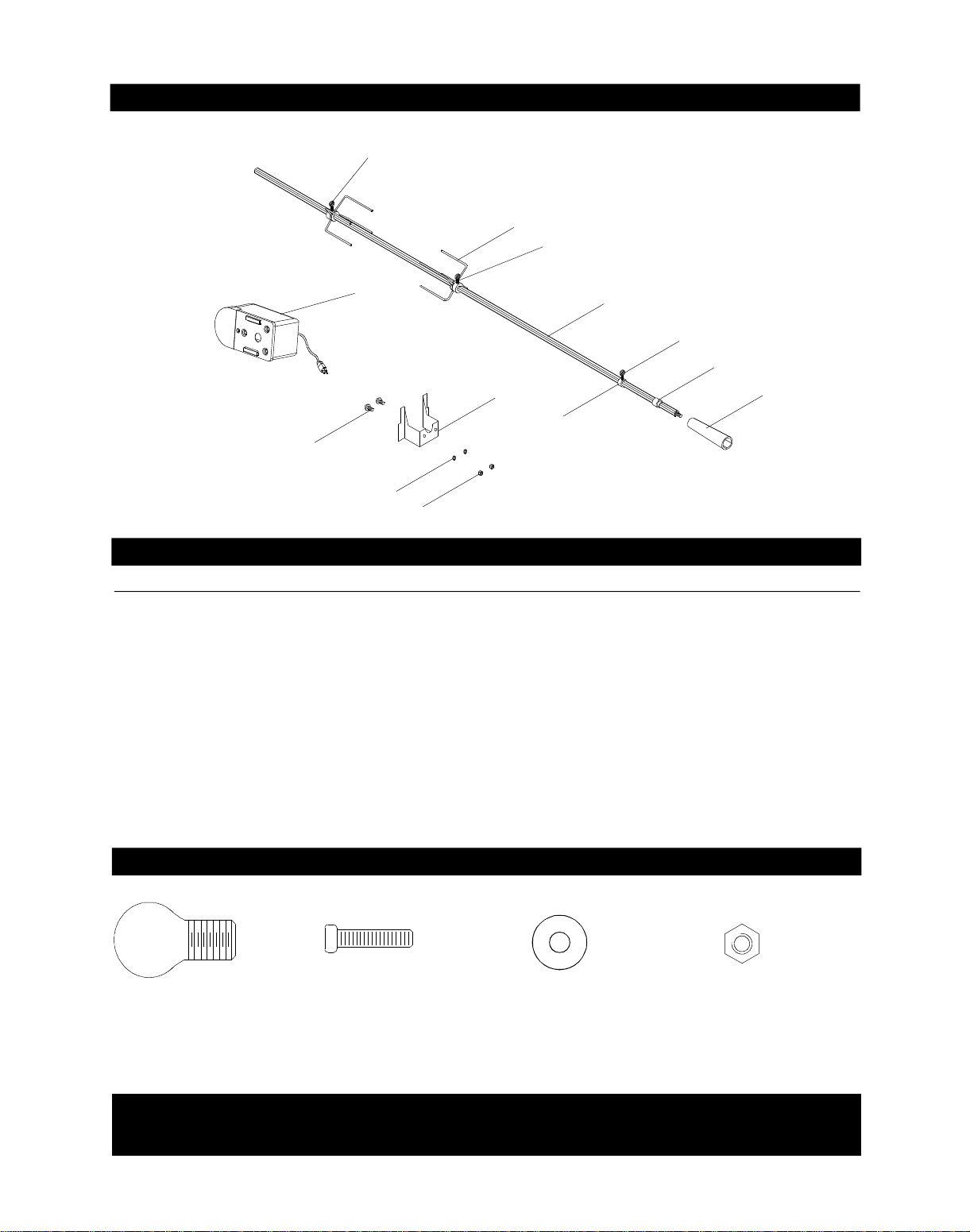
Y0250143 Rotisserie Assembly Parts Diagram
Grill Information Center: If you have questions about assembly or grill operation, or
if there are damaged or missing parts when you unpack this unit from the shipping box, call us
8:00 am - 4:30 pm CST, Monday through Friday at: 1-800-770-9769
Rot. Screw#10-24x3/4"
UNC
Qty. 2
Part# S112G10124
Rot. Thumbscrew
3/8"x1/2"
Qty. 3
Part# S196G06084
Rot. Washer
Qty. 2
Part# S411G03084
Rot. Nut#10-24
Qty. 2
Part# S362G10124
Y0250143 Rotisserie Assembly Parts List
KEY
PART#
DESCRIPTION
QTY
Rot. Handle
Rot. Bushing
Rot. Thumbscrew 3/8"x1/2"
Rot. Collar
Rot. Spit
Rot. Holding Fork
Rot. Motor Bracket
Rot. Motor/AC
Rot. Screw #10-24x3/4" UNC
Rot. Washer
Rot. Nut #10-24
1.
2.
3.
4.
5.
6.
7.
8.
9.
10.
11.
1
1
3
1
1
2
1
1
2
2
2
Hardware for Rotisserie
10
8
9
10
4
11
7
3
3
6
5
2
3
1
P05508004E
P05508092F
S196G06084
P05508091F
P05508146F
P05508090F
P03307010A
P07101045A
S112G10124
S411G03084
S362G10124
Assembly Instructions
Remove all packed components. Use the parts list to check that all necessary parts have been included.
Assemble the gas grill on a protective work surface to avoid scratching grill surfaces. Inspect your grill for damage
as you proceed. Do not assemble or operate your grill if it appears damaged.
Phillips Head Screw
3/16" x 3/8"
Qty. 4
Part # S112G0306B
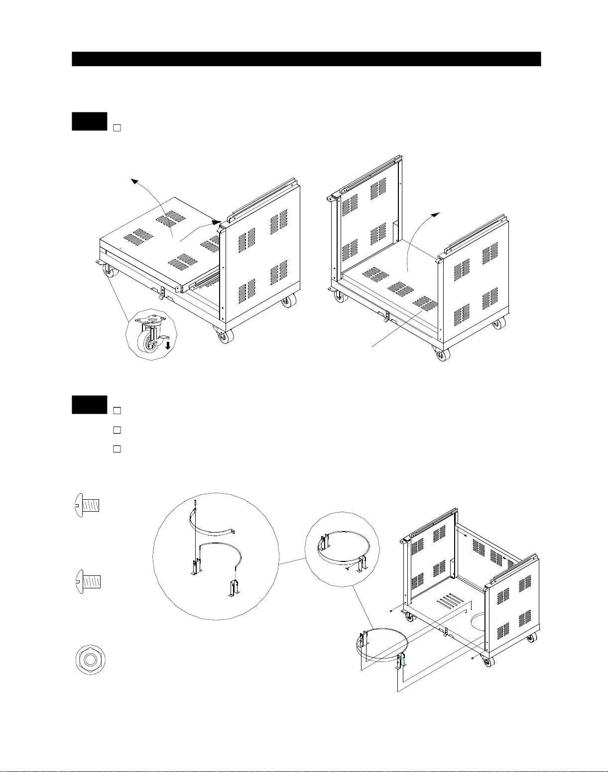
Secure the Cart Rear Panel between the Cart Side Panels using
2 of 3/16"x3/8" Phillips Head Screws.
Secure the Cart Side Panel, Left/Right using 2 of 3/16"x3/8"
Phillips Head Screws.
2
Install Cart Rear Panel and Cart Side Panels
Unfold the Cart Side Panel, Right, Cart Side Panel, Left and Cart
Rear Panel.
1
Assemble Cart
11
Cart Rear Panel
Flange Nut 3/16"
Qty. 4
Part # S313G0306B
Phillips Head Screw
3/16" x 1/2"
Qty. 4
Part # S112G0308B
Intall the Tank holder to Cart Bottom Shelf using 4 of 3/16"x1/2"
Phillips Head Screws and 4 of 1/4" Flange Nut.

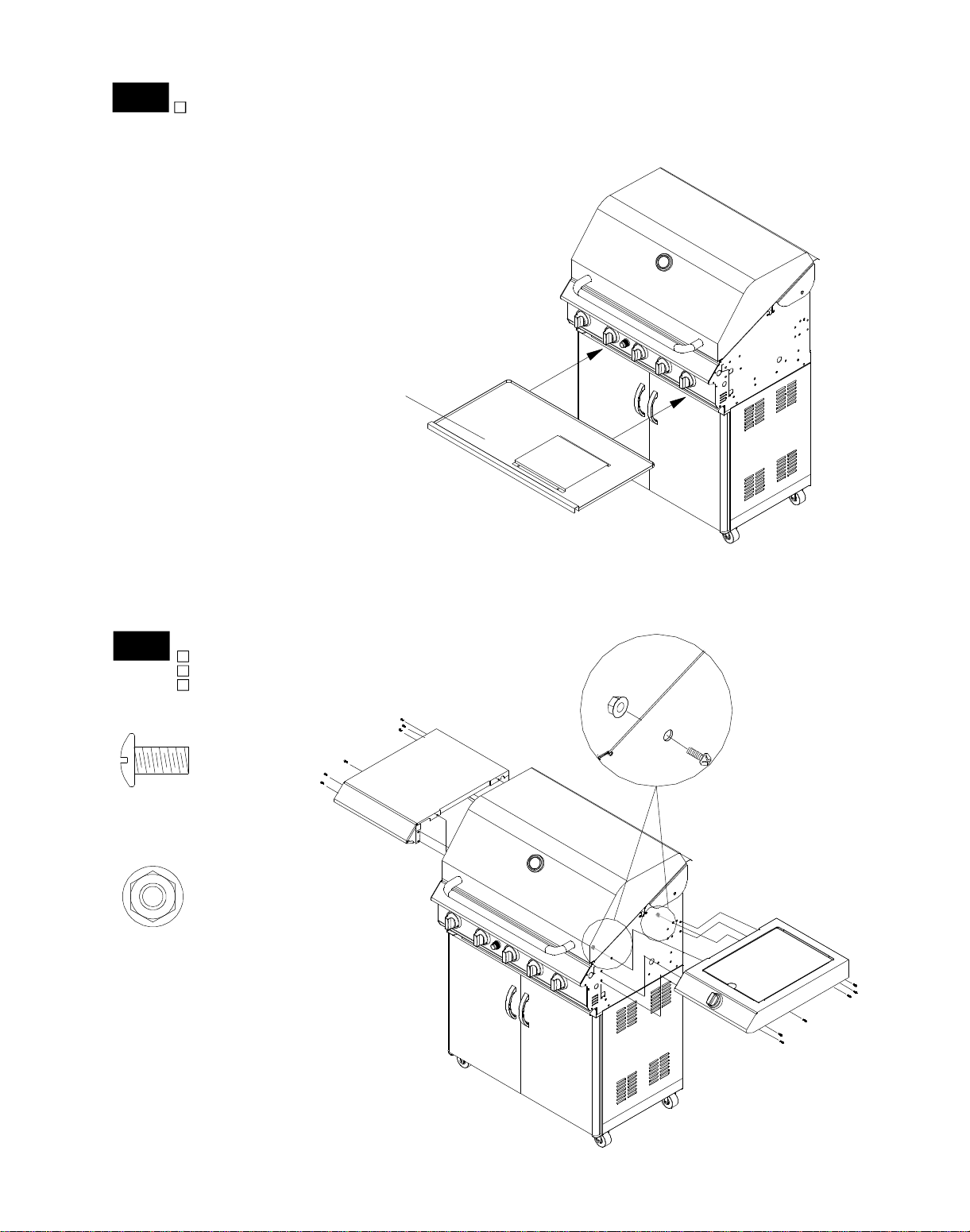
Door Handle
Qty. 2
Part # P00201001C
Intall the Door Handles to Doors using 4 of 3/16"x1/4" Phillips
Head Screws.
Install Door Handles, Partition Panel and Door
Install the Partition Panel Bracket between Partition Panel and
Cart Bottom Shelf using 3 of 3/16"x3/8" Phillips Head Screws.
Install the Partition Panel to Left Cart Side Panel and Cart
Rear Panel using 4 of 3/6"x3/8" Phillips Head Screws.
Phillips Head Screw
1/4" x 1-3/16"
Qty. 4
Part # S112G0419B
5
4
Install Door Bracket and Grill Bowl
Phillips Head Screw
3/16" x 3/8"
Qty. 2
Part # S112G0306B
Install the Door Bracket between the Left and Right Cart
Side Panel using 2 of 3/16" x 3/8" Phillips Head Screws.
12
Phillips Head Screw
3/16" x 1/4"
Qty. 4
Part # S112G0304E
Phillips Head Screw
3/16" x 3/8"
Qty. 7
Part # S112G0306B
3
Remove cooking components from Grill Head. With an
assistant, lift and position Grill Head on the Cart. Tighten
securely using 4 of 1/4" x 1-3/16" Phillips Head Screws.
Insert Bottom Left Door Hinge into Bottom Left Door Hinge
Bracket. Then align Top Door Hinge and insert into the hole
on Top Left Door Hinge Bracket.
Repeat both steps for Right Door.
5
Install Grease Tray
13
Grease Tray
Flange Nut 1/4"
Qty. 4
Part #
6
Install Left Side Shelf and Right Side Burner Frame
Phillips Head Screw
1/4" x 1/2"
Qty. 12
Part # S112G0408E
S313G0408E
From the front of the grill, slide the Grease Tray side tabs over the
side rails underneath the Grill Bowl.
Attach the Side Shelf to the left Bowl Panel.
Tighten securely by using Screws and Nuts provided.
Repeat both steps for Right Side Burner Frame.

7
Install Side Burner Connection Hose
S
o
c
k
e
t
P
l
u
g
Hose Holder
Sleeve
8
Install Regulator Assembly
Hose Holder
Qty. 2
Part # P05536001Z
Scale 1:2
Flange Nut 3/16"
Qty. 4
Part # S313G0306B
Phillips Head Screw
3/16" x 3/8"
Qty. 4
Part # S112G0306B
14
LPG Regulator
Cart Rear Panel
Hose
Hose
Holder
Figure A
Figure B
Figure C
SLEEVE
SLEEVE
SOCKET
PLUG
Push back Sleeve of the Socket. See Figure A.
Insert Plug then release Sleeve. See Figure B.
Push Plug until sleeve snaps forward locking the
Plug into the Socket. See Figure C.
Push the Side Burner Hose into hose holder.
Place the LPG Regulator inside the cart through the
opening above Cart Rear Panel. Fix the hose of LPG
Regulator by Hose Holder onto Cart Rear Panel.
Tighten securely by using Screws and Nuts provided.

Be sure all Control Knobs are set to
"OFF" and open the Grill Lid.
Have your assistant stand behind to the
right of the grill and look toward the front
of the grill bowl. Never put your face
inside the Grill Head.
Push the Igniter Cap in and have
assistant watch for a blue spark within
each Gas Collector Box. If a spark is
present the Electrode Tips are properly
positioned.
Place the Savor Plates
®
above the
Burners.
Place the Cooking Grids on the ledge
above the Savor Plates®.
Place the Secondary Cooking Rack on
the slots on either side of the Grill
Bowl.
Savor Plates
Cooking Grids
Secondary Cooking Rack
®
Install Ignitor Battery
9
Unscrew Ignitor Cap from Control Panel.
Place supplied AA battery into the Ignitor
Slot with positive pole facing you.
Position the Cap and Spring over the AA
battery and tighten onto Control Panel.
With the assistance of another person,
perform this Electrode Check before
proceeding.
10
This test will ensure that the Spark Electrode Tips
are properly positioned so your grill lights easily
and properly.
Ignitor Slot
AA Battery
Ignitor Cap
Spring
Install Cooking Components
15
3/16"
Spark Gap
Gas Collector Box
Spark Electrode Tip
Spark Receiver
Side Burner Electrode Check
11
Open side burner lid. Remove plastic
shipping band from burner and pot
support.
Push and turn side burner Control Knob
to HIGH. Look for spark between tip of
electrode and burner.
If you don't see a spark from side burner electrode, adjust gap between electrode and
burner surface to 3/16 in.
Final Grill Assembly Step
When you have finished assembling your
grill be sure that all screws are tightened
for safe operation of your grill.
Failure to read and follow the Use and Care
Instructions could result in a fire or explosion
that could cause serious bodily injury, death or
property damage.
WARNING
!!
+
_
12

Optional Wind Shield for More Effective Cooking
When cooking with only the main burners you can generate more heat for your cooking if you
place the wind shield on your cooking grid. If the searing burner is in operation there is no need
for the wind shield.
13
Open lid and remove the secondary cooking rack.
Before igniting burners, tilt the cooking grid up at the middle point of the grill. See Fig. 1.
Place the base of the wind shield in-between the cooking grids and then lower
the cooking grid to its original position. See Fig. 2.
Replace the secondary cooking rack.
The Right Rack
Fig. 1.
Bowl Wind Shield
The Right Rack
Fig. 2.
Bowl Wind Shield
16
Do NOT Touch after cooking.
WARNING
!!
Fig. 1.

USE AND CARE INSTRUCTIONS
CORRECT LP GAS TANK USE
LP Gas grill models are designed for use with a
standard 20 lb. Liquid Propane Gas (LP Gas) tank,
not included with grill. Never connect your gas grill to
an LP Gas tank that exceeds this capacity. A tank of
approximately 12 inches in diameter by 18-1/2 inches
high is the maximum size LP Gas tank to use. You
must use an "OPD" gas tank which offers a listed
Overfill Prevention Device. This safety feature
prevents tank from being overfilled which can cause
malfunction of LP Gas tank, regulator and/or grill.
Never connect an unregulated LP gas tank to your
gas grill. The gas regulator assembly supplied with
your gas grill is adjusted to have an outlet pressure
of 11" water column (W.C.) for connection to an LP
gas tank. Only use the regulator and hose assembly
supplied with your gas grill. Replacement regulators
and hose assemblies must be those specified by
the Manufacturer.
Have your LP Gas dealer check the release valve
after every filling to ensure it remains free of defects.
Always keep LP Gas tank in upright position.
Do not subject the LP Gas tank to excessive heat.
Never store an LP Gas tank indoors. If you store
your gas grill in the garage always disconnect the
LP Gas tank first and store it safely outside.
LP Gas tanks must be stored outdoors in a wellventilated area and out of the reach of children.
Disconnected LP Gas tanks must not be stored in a
building, garage or any other enclosed area.
The regulator and hose assembly can be seen after
opening the doors (if applicable) and must be
inspected before each use of the grill. If there is
excessive abrasion or wear or if the hose is cut, it
must be replaced prior to using the grill again.
Never light your gas grill with the lid closed or
before checking to ensure the burner tubes are fully
seated over the gas valve orifices.
Never allow children to operate your grill. Do not
allow children or pets to play near your grill.
Keep fire extinguisher readily accessible. In the
event of a oil/grease fire, do not attempt to
extinguish with water. Use type B extinguisher
or smother with dirt, sand or baking soda.
In the event of rain, cover the grill and turn off
the burner and gas supply.
Use your grill on a level, stable surface in an
area clear of combustible materials.
Do not leave grill unattended when in use.
Do not move the appliance when in use.
Allow the grill to cool before moving or storing.
Do not use your grill as a heater.
This grill is not intended to be installed in
or on recreational vehicles and/or boats.
Never use charcoal in this gas grill.
17
The LP Gas tank must be constructed and marked
in accordance with the Specifications for LP-Gas
Cylinders of the U.S. Department of Transportation
(D.O.T.) or the National Standard of Canada, CAN/
CSA-B339, Cylinders, Spheres and Tubes for Transportation of Dangerous Goods; and Commission,
as applicable.
The LP Gas tank must have a shutoff valve,
terminating in an LP Gas supply tank valve outlet,
that is compatible with a Type 1 tank connection
device. The LP Gas tank must also have a safety
relief device that has a direct connection with the
vapor space of the tank.
The tank supply system must be arranged for
vapor withdrawal.
The LP Gas tank used must have a collar
to protect the tank valve.
•
•
•
WARNING
!!
Do not store a spare LP-Gas tank under or near
this appliance.
Never fill the tank beyond 80 percent full; and
If the information in "(a)" and "(b)" is not followed
exactly, a fire causing death or serious injury may
occur.
A.
B.
C.
Use your grill at least 3 feet away from any
wall or surface. Use your grill at least 3 feet
away from combustible objects that can melt
or catch fire such as vinyl or wood siding, fences
and overhangs or sources of ignition including pilot
lights on water heaters and live electrical appliances.
Outdoor cooking gas appliance shall not be used
under overhead combustible construction.
Never use your gas grill in a garage, porch, shed,
breezeway or any other enclosed area.
Never obstruct the flow of ventilation air around your
gas grill housing.
In windy conditions, always position the front of grill to
face oncoming wind to reduce smoke and heat blowing in
your face and prevent potential hazards to self and grill.
WARNING
!
!
•
3ft.
3ft.
WIND
DIRECTION
•
Use of alcohol, prescription or non-prescription
drugs can impair your ability to properly assemble
and safely operate your grill.

18
USE AND CARE INSTRUCTIONS
NOTE about LP Gas Tank Exchange Programs
Many retailers that sell grills offer you the option of
replacing your empty LP Gas tank through an exchange service. Use only those reputable exchange
companies that inspect, precision fill, test and certify
their tanks. Exchange your tank only for an OPD safety
feature-equipped tank as described in the LP Gas tank
section of this manual.
Ÿ
How to Leak Test your LP Gas Tank
If growing bubbles appear do not use or move
the LP Gas tank. Contact an LP Gas Supplier
or your fire department!
WARNING
!
!
Use a clean paintbrush and a 50/50 mild soap and
water solution.
Brush soapy solution onto LP Gas tank in the
areas indicated by the arrows. See diagram.
If growing bubbles appear do not use or move the
LP Gas tank. Call an LP Gas Supplier or your Fire
Department.
All leak tests must be repeated each time your LP
Gas tank is exchanged or refilled.
When checking for gas leaks do not smoke.
Do not use an open flame to check for gas leaks.
Your grill must be leak tested outdoors in a well-
ventilated area, away from ignition sources such as
gas fired or electrical appliances. During the leak test,
keep your grill away from open flames or sparks.
Do not use household cleaning agents. Damage to
gas assembly components can result.
Ÿ
Ÿ
Ÿ
Ÿ
Ÿ
Ÿ
Ÿ
For your safety:
Leak test new and exchanged LP Gas tanks BEFORE
connecting one to your grill.
Always keep new and exchanged LP Gas tanks in an
upright position during use, transit or storage.
LP Gas Model only:
Secure a 20lb LP Gas Tank to Gas Grill or
Range
One Nut is fixed to
Tank Holder. An
additional Nut and
Wing Bolt is secured
AFTER inserting tank
into tank hole.
Wing Bolt 1/4"x1/2"
Qty. 1
Part # S233G0408B
Additional Nut
Turn your LP Gas Tank Valve clockwise to the
closed or OFF positon.
Unscrew the Wing Bolt from right bracket of tank
holder.
Place LP Gas tank into tank holder on the Tank
Tray.
Install the tank so the Tank Valve faces the rear
right corner of cabinet.
Align an additional nut and screw the Wing Bolt
into right bracket of tank holder to secure the
gas tank.

USE AND CARE INSTRUCTIONS
Check all connections for LP Gas Leaks
Never test for leaks with a flame. Prior to first use,
at the beginning of each season, or every time
your LP Gas tank is changed, you must check for
gas leaks. Follow these three steps:
Make a soap solution by mixing one part liquid
detergent and one part water.
Turn the grill Control Knobs to the full OFF
position, then turn the gas ON at source.
Apply the soap solution to all gas connections
indicated by the arrows. See diagram. If
bubbles appear in the soap solution the
connections are not properly sealed. Check
each fitting and tighten or repair as necessary.
Gas Valve / Manifold Assembly
Regulator with Hose (LPG)
LP Gas Tank
If you have a gas leak that cannot be repaired by
tightening, turn off the gas at the source, disconnect
fuel line from your grill and call 1-800-770-9769
or your gas supplier for repair assistance.
Never disconnect the gas regulator or any gas
fitting while your grill is lit. A lit grill can ignite
leaking gas and cause a fire or explosion which
could result in property damage, personal injury
or death.
WARNING
! !
LP Gas Model only:
Connect Regulator with Hose to your LPG Tank
Turn all Burner Valves to the OFF position.
Inspect the valve connection port and regulator
assembly for damage or debris. Remove any
debris. Never use damaged or plugged
equipment.
Connect the regulator assembly to the tank valve
and HAND TIGHTEN nut clockwise to a full stop.
DO NOT use a wrench to tighten because it could
damage the Quick Coupling Nut and result in a
hazardous condition.
Open the tank valve 1/4 to 1/2 (counterclockwise)
and use a soapy water solution to check all
connections for leaks before attempting to light
your grill. See "Checking for LP Gas Leaks". If
a leak is found, turn the tank valve off and do not
use your grill until the leak is repaired.
Type 1 connection per
ANSI Z21.58- 2007
Quick
Coupling Nut
CAUTION: When the appliance is not in use the gas
must be turned off at the tank.
Before using this gas appliance read all
instructions and perform all gas leak-check
procedures even if the product was
pre-assembled by the retailer or manufacturer.
WARNING
! !
Disconnecting A Liquid Propane Gas (LPG)
Tank From Your Grill
Make sure the Burner Valves and LP Gas tank valve
are off. (Turn clockwise to close.)
Detach the hose and regulator assembly from the
LP Gas tank valve by turning the Quick Coupling
Nut counterclockwise.
19
Place dust cap on cylinder valve outlet whenever the
cylinder is not in use. Only install the type of dust
cap on the cylinder valve outlet that is provided with
the cylinder valve. Other types of caps or plugs may
result in leakage of propane.
20
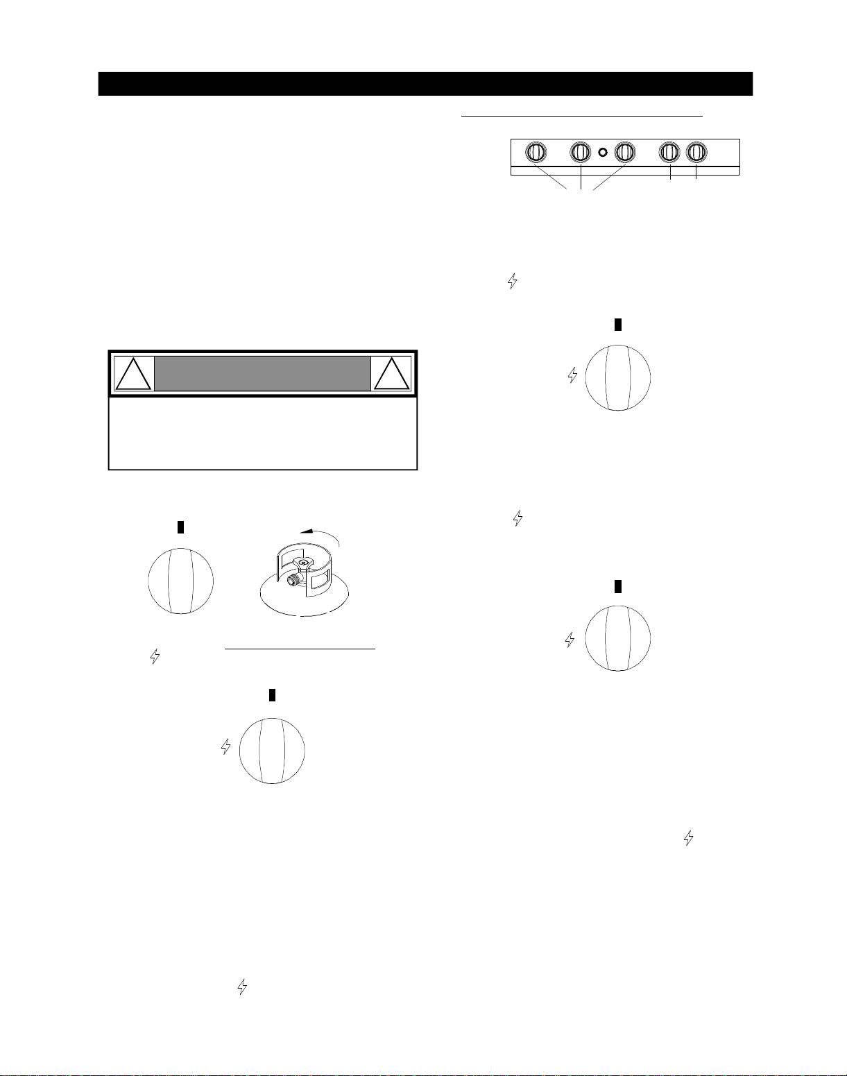
Grill Lighting Instructions
Set Control Knobs to OFF and open the LP Gas
SLOWLY 1/4 of a turn.
Push and turn the Main Burner Control Knob to
ON/ . Always light the LEFT Main Burner first.
Press the electric ignitor 3 to 4 seconds to light the
burner.
If ignition does not occur in 5 seconds, turn gas off
at source and turn Control Knobs OFF. Wait at least
5 minutes for gas to clear, then retry. If your grill still
fails to light turn the burner Control Knob(s) and gas
source OFF and conduct a leak test of ALL gas
connections and gas sources as explained in the
Use and Care section of this manual. If no leaks are
detected, wait 5 minutes for any gas to clear and
repeat the lighting procedure.
After one Burner is lit, turn the tank valve SLOWLY
one more 1/4 of a turn for 1/2 of one complete turn.
Repeat steps to light each burner individually. Turn
other burners to ON/ to light as you move towards
the fuel source.
IMPORTANT: Do not use the Back Burner and
Main Burners at the same time. Backburner is
for Rotisserie Cooking only.
Follow steps 1 through 6 of the Grill Lighting
Instructions.
Then, push and turn the Infrared Burner Control Knob
to ON/ and press the electric ignitor 3 to 4 seconds
to light the burner. Hold the knob in 10 seconds before releasing. If ignition does not occur follow step 7
before retrying.
After the Infrared Burners is lit it will reach cooking
temperature quickly. The orange/red glow will even
out within minutes.
ON/
ON/
Back Burner Lighting Instructions
Follow steps 1 through 6 of the Grill Lighting
Instructions.
Then, push and turn the Back Burner Control Knob
to ON/ and press the electric ignitor 3 to 4
seconds to light the Burner. Hold the knob in 10
seconds before releasing. If ignition does not occur
follow step 7 before retrying.
1.
3.2.After the Back Burner is lit it will reach cooking
temperature quickly. The orange/red glow will
even out within minutes.
Infrared Burner Lighting Instructions
1.
3.
2.
Burner Control Knobs on Control Panel
OFF
Grill
Main Burner
Back
Burner
Infrared
Burner
Follow steps 1 through 5 of the Grill Lighting
Instructions.
Set Control Knob to OFF and open the LP Gas tank
valve SLOWLY 1/4 of a turn.
Push and turn the Control Knob to ON/ . The built
spark ignitor will light the Burner automatically.
You may have to pusk and turn the Control Knob up to
3 to 4 times to light.
If ignition does not occur, turn the burner Control Knob
and gas source OFF and conduct a leak test of ALL
gas connections and fuel sources. If no leaks are
detected, wait 5 minutes for any gas to clear and repeat the lighting procedure.
1.
Side Burner Lighting Instructions
2.
3.
4.
5.
6.
USE AND CARE INSTRUCTIONS
5.
4.
3.
2.
1.
6.
tank valve
Open LP
gas tank
9.
8.
7.
Failure to replace a faulty hose, secure gas supply
connections or to open the Lid before proceeding
to the Lighting Procedures could result in a fire
or explosion that could cause serious bodily injury,
death, or property damage.
WARNING
!
!
OFF
ON/
OFF
LOW
OFF
Before each use, check all hoses for cracks, nicks, cuts,
burns or abrasions. If a hose is damaged in any way, do
not use your grill before replacing the hose with an
authorized part from the Parts List. Also make sure all
gas supply connections are securely tightened.
Familiarize yourself with the safety and Use and Care
instructions in this manual. Do not smoke while lighting
grill or checking gas supply connections.
Be sure the LP Gas tank is filled.
Open the Grill Lid during lighting.
Check that the end of each Burner Tube is properly
located over each Valve Orifice (see page 25).
Open Side Burner Lid.
 Loading...