

Members Mark M3905alp, M3905ang, M3905alp, M3905ang Owner's Manual


Table of Contents
Primary Safety Warnings...........................1-3
Warranty Terms and Conditions..................2
Pre-Assembly Instructions..............................3
Part Diagrams and Lists..........................4-8
Assembly Instructions...............................9-10
Use & Care Instructions:
• Gas Safety and Leak Tests...........11-14
• Lighting Instructions............................15-16
• Troubleshooting..........................................16
• Rotisserie Instruction...........................17-18
• Cleaning and Maintenance................19-20
• Cooking Guide...................................A1-A5
• Frequently Asked Questions............A6-A7
Warranty
Full 1-Year Warranty on Grill
For one year from the date of purchase, the
Manufacturer will repair or replace, at our
option, any grill part (except for paint loss,
rusting and ignitor battery) that is defective in
material or workmanship.
Limited Warranty on Selected Grill Parts
From one year after the date of purchase for
the designated time periods listed below, the
Manufacturer will replace the following grill parts
if they are defective in material or workmanship.
You will be charged for shipping and handling.
Lifetime: Tube Burners and Stainless Steel parts
•
(except for discoloration due to normal use or
excessive heat, and scratches or dents caused
by normal use and improper maintenance).
2 Years: All Other Grill Parts (except Ceramic
•
Savor Plates™, cooking grids and ignitor battery).
Warranty Service
Warranty service is available by contacting
1-800-770-9769.
Warranty Restrictions
•
This warranty is void if grill is used for
commercial or rental purposes.
•
This grill is safety certified for use only in
the country where purchased. Modification for
use in any other location is a safety hazard
and will void the warranty.
•
This warranty gives you specific legal rights,
and you may also have other rights which
vary from state to state.
! !
DANGER
IF YOU SMELL GAS:
Shut off gas to the appliance.
1.
Extinguish any open flame.
2
Open lid.
3.
If odor continues, keep away from
4.
the appliance and immediately call
your gas supplier or your fire
department.
! !
Do not store spare LP cylinder
1.
WARNING
within 10 feet (3m) of this appliance.
Do not store or use gasoline or
2.
other flammable liquids and
vapors within 25 feet (8m) of this
appliance.
When cooking with oil/grease, do
3.
not allow the oil/grease to get
hotter 350°F (117°C)
Do not leave oil/grease unattended.
4.
! !
•
•
•
•
WARNING
LPG grill models must be used with Liquid
Propane Gas and the regulator assembly
supplied. Natural Gas models must be used
with Natural Gas only. Any attempt to convert
the grill from one fuel type to another is
extremely hazardous and will void the
warranty.
Never use your gas grill in a garage, porch, shed,
breezeway or any other enclosed area.
Never obstruct the flow of ventilation air around
your gas grill housing.
Keep gas regulator hose away from hot grill
surfaces and dripping grease. Avoid unnecessary twisting of hose. Visually inspect hose
prior to each use for cuts, cracks, excessive
wear or other damage. If the hose appears
damaged do not use the gas grill. Call:
1-800-770-9769 for an authorized replacement
hose.
Manufacturer:
Grand Hall Enterprise Co., Ltd.
9th Fl., No.298, Rueiguang Rd., Neihu,
Taipei, Taiwan (114)
Grill Installation Codes
The installation must conform with local codes or, in the
absence of local codes, with either the National Fuel Gas
Code, ANSI Z223.1/NFPA 54, or CAN/CGA-B149.1, Natural
Gas and Propane Installation Code.
2

Pre-Assembly Instructions For Your Safety
! !
Failure to comply with these instructions may
result in a hazardous situation which, if not
avoided, may result in injury.
Spiders and small insects can spin webs and
nest in the grill Burner Tubes during transit and
warehousing which can lead to a gas flow
obstruction resulting in a fire in and around the
Burner Tubes. This type of "FLASHBACK FIRE"
can cause serious grill damage and create an
unsafe operating condition for the user.
CAUTION
To reduce the chance of FLASHBACK
FIRE you must clean the Burner Tubes
as follows before assembling your grill.
Also do this at least once a month in summer
and fall or whenever spiders are active in your
area, and if your grill has not been used for an
extended period of time.
1. Remove the cotter pin from the rear of each Main
Burner using long nose pliers.
2. Carefully lift each Burner up and away from the
Gas Valve Orifice.
3. Check and clean Burner/Venturi Tubes for insects
and insect nests. A clogged tube can lead to a fire
beneath the grill.
4. Refer to the figure below and perform one of
these 3 cleaning methods:
METHOD 1: Bend a stiff wire or wire coat
hanger into a small hook as shown and run
the hook through the Burner Tube and inside
the Burner several times to remove debris.
TO CLEAN BURNER TUBE, INSERT HOOK
HERE
! !
For safe operation ensure the Gas Valve Assembly Orifice is inside the Burner Tube before using
your grill. See figure. If the Orifice is not inside
the Burner Tube, lighting the Burner may cause
explosion and/or fire resulting in serious bodily
injury and/or property damage.
Gas Valve Assembly
To expedite the assembly process follow these
general guidelines:
WARNING
Orifice
Burner Tube
Tools Required for Assembly include:
protective work gloves
•
protective eyewear
•
Phillips Head Screwdriver
•
long nose pliers
•
While it is possible for one person to unpack this gas
grill, obtain assistance from another person when
handling the large pieces.
Use the Hardware and Part Diagrams to ensure all
items are included and free of damage.
Do not assemble or operate the grill if it appears
damaged. If there are damaged or missing parts when
you unpack the shipping box or you have questions
during the assembly process, call the:
Grill Information Center 1-800-770-9769
8am-4:30pm CST, Monday through Friday
9
Burner Tube
METHOD 2: Use a bottle brush with a flexible
handle and run the brush through the Burner
Tube and inside the Burner several times to
remove any debris.
METHOD 3: Use an air hose to force air
through each Burner Tube. The forced air
should pass debris or obstructions through the
Burner and out the Ports.
3
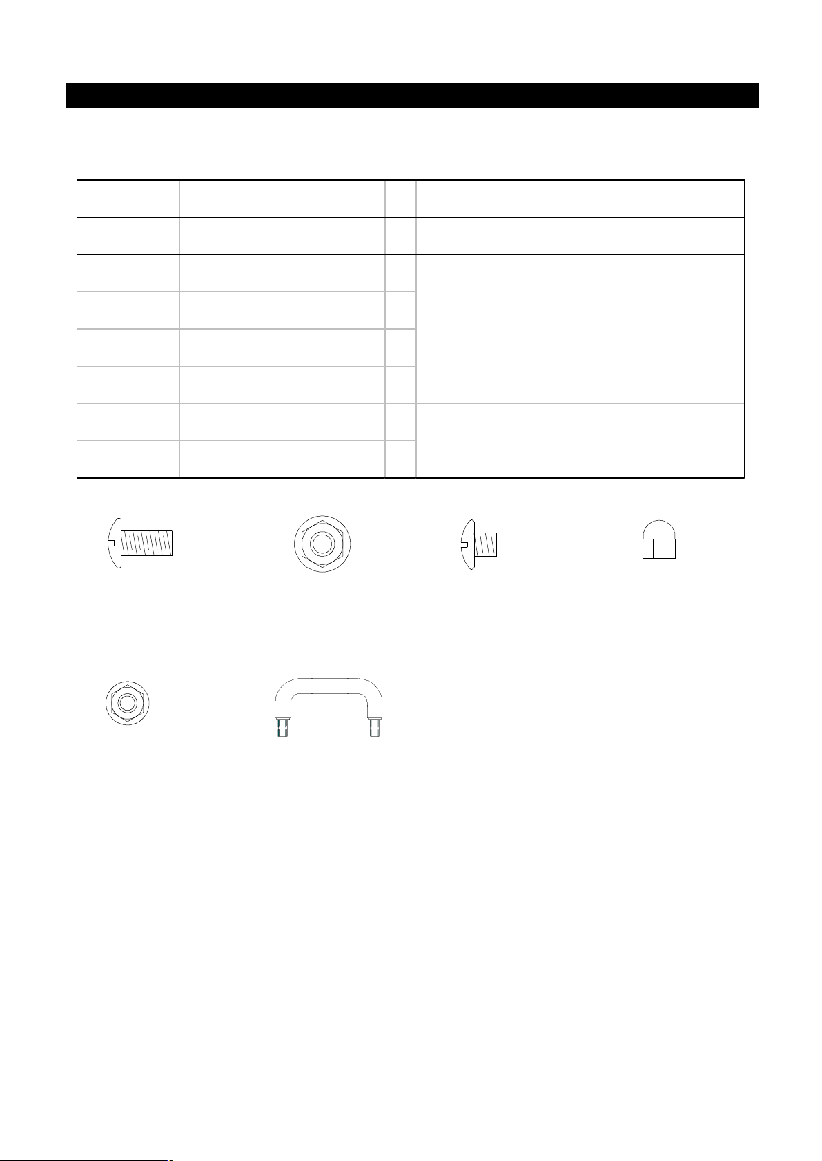
Hardware Pack Parts List for Model M3905ALP & M3905ANG
PART #PART DESCRIPTIONQTYPURPOSE OF PART
P06002020AHardware Pack1For use in assembly
S112G04081Phillips Head Screw 1/4"x1/2"10
S313G04081Flange Nut 1/4"4
Attaches Side Shelf Brackets To Grill
S112G04061Phillips Head Screw 1/4"x3/8"2
S322G04061Cap Nut 1/4"2
S313G03061Flange Nut 3/16"8
Attaches Side Shelves to Side Shelf Brackets
P05501017ASide Shelf Lock4
Phillips Head Screw 1/4"x1/2"
Qty. 10
Ref.# S112G04081
Flange Nut 3/16"
Qty. 8
Ref.# S313G03061
Flange Nut 1/4"
Qty. 4
Ref.# S313G04081
Side Shelf Lock
Qty. 4
Ref.# P05501017A'
Scale: 1:2
Phillips Head Screw 1/4"x3/8"
Qty. 2
Ref.# S112G04061
Cap Nut 1/4"
Qty. 2
Ref.# S322G04061
* Two Batteries/AA included in the Hardware Pack.
4

Parts Diagram for Model M3905ALP & M3905ANG
5

Parts List for Model M3905ALP & M3905ANG
KEYDESCRIPTIONPART#QTY
1Lid AssemblyY01100361
1ALid HingeP05332003A2
2Temperature GaugeP00601171A1
3Lid Handle Bracket, LeftP00301016E1
4Lid Handle Bracket, RightP00302016E1
5Lid HandleP00205061A1
6Lid Handle Heat-Insulating SpacerP06801002A2
7Protective PadP05518002I4
8Cooking Rack/SecondaryP01517003B1
9Cooking GridP01604009B4
10Savor Plate, CeramicP01804006A9
11Savor Plate, RackP01717003E3
12Burner/Main P02008004A3
13Gas Collector Box with Electrode P02609001B3
14Infrared Burner AssemblyP02005004A1
15Infrared Burner Electrode P02614010C1
16Infrared Burner ThermocoupleP05305008A1
17Infrared Burner Electrode BracketP03328016C1
18Infrared Burner Electrode ProtectorP06909003C1
19Control Panel, UpperP02909091S1
Control Panel, Lower (LPG only)P02910106B1
20
Control Panel, Lower (NG only)P02910116G1
21Electric Ignitor, 4-portP02502134C1
22Control Knob SeatP03415014A5
23 Control Knob with Rubber Ring for Main Burner P03411053L 3
24 Control Knob with Rubber Ring for Back/Infrared Burner P03411063L 2
25Name PlateP00414005Q1
26Electric Ignitor, 2-portP02502192C1
Gas Valve/Manifold Assembly (LPG only)Y00601901
27
Gas Valve/Manifold Assembly (NG only)Y00601911
28Electric Wire SetP02615074A1
29Grease Draining PlateP06902003C2
30Grease TrayP02705165B1
31Grease Tray Heat Shield, LowerP06903028A1
32Grease Tray HandleP00213001B1
33Bowl Partition PanelP07523002A1
34Bowl Panel, LeftP0072043EC1
35Bowl Panel, RightP0072143EC1
36Bowl Panel, FrontP0073843DC1
37Bowl Panel, RearP0072543DC1
38Grease Tray Heat Shield, UpperP06903029A1
39Grease Tray Heat Shield, ExtensionP06903030B1
40Burner BracketP02203114A1
41Back Burner AssemblyY03100181
Back Burner Orifice (LPG only)P06527001A1
42
Back Burner Orifice (NG only)P06527002A1
6

Parts List for Model M3905ALP & M3905ANG
KEYDESCRIPTIONPART #QTY
43Back Burner Extension TubeP03717019A1
44Back Burner ElectrodeP02614011C1
45Back Burner ThermocoupleP05305009A1
46Back Burner Electrode ProtectorP03328016C1
47Back Burner Electrode BracketP06909004C1
48Back Burner Wind ShieldP06905012B1
49Cart Rear Wind ShieldP06906018C1
50Regulator with Hose (LPG)P03631001A1
51Side ShelfP01105002B2
52Side Shelf Bracket, LeftP01209003A1
53Side Shelf Bracket, RightP01210003A1
54Side Shelf LockP05501017A4
55Bowl BracketP03306015C1
56Door, LeftP04302025A1
57Door, RightP04303025A1
58Door HandleP00214028H2
59Door Bracket, LeftP03314009C1
60Door Bracket, RightP03314010C1
61Bowl Support BracketP01303004B2
Cart Side Panel, Left (LPG only)P07602010A1
62
Cart Side Panel, Left (NG only)P07602011A1
63Cart Side Panel, RightP07603010A1
Cart Bottom Shelf (LPG only)P01009006C1
64
Cart Bottom Shelf (NG only)P01009007C1
65Cart Rear Panel P07701044A1
66Cart SupportP01907005B1
67Door MagnetP05523001K4
68Tank Pull-Out Tray AssemblyY03400381
69Caster Seat, LFP05327009T1
70Caster Seat, LRP05327010T1
71Caster Seat, RFP05327011T1
72Caster Seat, RRP05327012T1
73Caster, 2.5 in., with BrakeP05110004D4
Cart Spice Basket (LPG only)P05204005B1
74
Cart Spice Basket (NG only)P05204005B2
75Lighting StickP05507031E1
76Regulator Assembly / NGY0800071
77Hose, 12ft. / NGP03703001A1
78Extension Hose / NGP03705020A1
79Door Guide PlateP05510014A1
Hardware PackP06002020A1
Operator's ManualP80108001H1
Grill CoverP07007016A1
For the repair or replacement parts you need:
Call our Grill Information Center at 1-800-770-9769
To obtain the correct replacement parts for your gas grill, please refer to the part numbers in this parts
list. The following information is required to ensure you receive the correct parts:
1. Model and Serial Number (see CSA label on grill)
2. Part Number
3. Part Description
4. Quantity of parts needed
Important: Use only factory authorized parts. The use of any part that is not factory authorized can be
dangerous and will also void your product warranty. Keep this Operator's Manual for convenient referral
and for part replacement.
7

Y0250076 Rotisserie Assembly Parts Diagram
3
6
3
KEY
10.
11.
DESCRIPTION
1.
Rot. Handle
2.
Rot. Bushing
3.
Rot. Thumbscrew 3/8"x1/2"
4.
Rot. Collar
5.
Rot. Spit
6.
Rot. Holding Fork
7.
Rot. Motor Bracket
8.
Rot. Motor/AC
9.
Rot. Screw #10-24x3/4"
Rot. Washer
Rot. Nut #10-24
8
5
3
7
4
9
10
11
Y0250076 Rotisserie Assembly Parts List
PART#
P05508004E
P05508092F
S196G06084
P05508091F
P05508145F
P05508090F
P03307028A
P07101008B
S112G10124
S411G03084
S362G10124
QTY
1
1
3
1
1
2
1
1
2
2
2
2
1
Hardware for Rotisserie
Rot. Thumbscrew
3/8"x1/2"
QTY. 3
Ref.# S196G06084
Grill Information Center: If you have questions about assembly or grill operation, or
if there are damaged or missing parts when you unpack this unit from the shipping box, call us
8:00 am - 4:30 pm CST, Monday through Friday at: 1-800-770-9769
Rot. Screw#10-24x3/4"
UNC
QTY. 2
Ref.# S112G10124
Rot.Washer
QTY. 2
Ref.# S411G03084
8
Rot. Nut.#10-24
QTY. 2
Ref.# S362G10124

Assembly Instructions
1
Phillips Head Screw 1/4"x1/2"
Qty. 10
Ref.# S112G04081
Flange Nut 1/4"
Qty. 4
Ref.# S313G04081
Phillips Head Screw 1/4"x3/8"
Qty. 2
Ref.# S112G04061
Install Side Shelf Brackets
Align the holes on Right Side Shelf Bracket with the
threaded holes and holes on right side of grill. Tighten
securely using 6 Screws and 3 Nuts provided.
Repeat for Left Side Shelf Bracket.
Cap Nut 1/4"
Qty. 2
Ref.# S322G04061
2
Flange Nut 3/16"
Qty. 8
Ref.# S313G03061
Side Shelf Lock
Qty. 4
Ref.# P05501017A
Scale: 1:2
Install Side Shelves
Install Right Side Shelf to Right Side Shelf Bracket.
Tighten securely using 2 Locks and 4 Nuts provided.
Repeat for Left Side Shelf.
9
 Loading...