

Member's Mark 8 Cube Room Organizer, NOA8RO-WG-E, HAN8RO-DO-E, DYL8RO-R-E Instruction Manual
THIS INSTRUCTION BOOKLET CONTAINS IMPORTANT SAFETY INFORMATION.
PLEASE READ AND KEEP FOR FUTURE REFERENCE.
Date 2015-11-25 Rev. 1 Factory: KONRIC (16086)
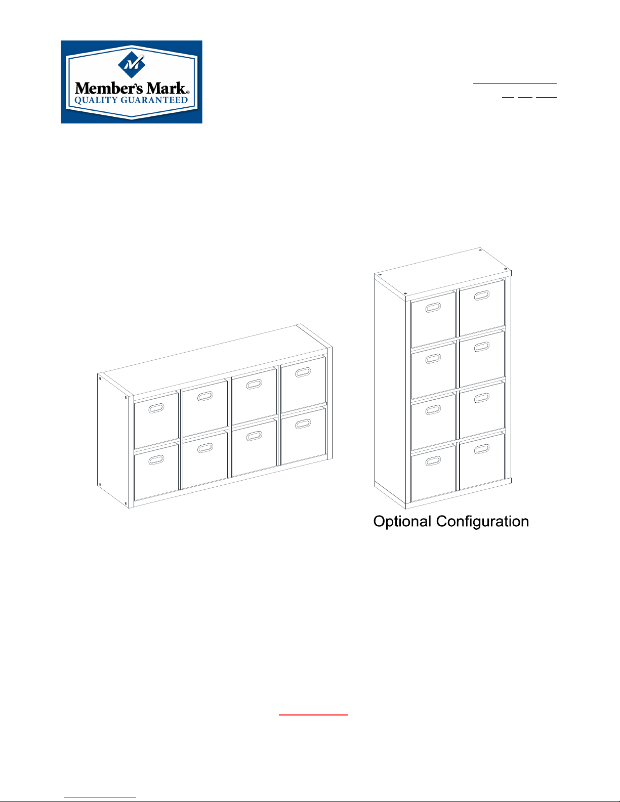
8 Cube Room Organizer
Stock # DYL8RO-R-E Rustic
Stock # HAN8RO-DO-E Dark Oak
Stock # NOA8RO-WG-E Warm Gray
ADULT ASSEMBLY REQUIRED
We would like to hear from you with any comments or suggestions. In the continental U.S. or Canada,
you can call us toll-free at 1-888-301-0332 from 8:00 a.m. to 5:00 p.m., CST, Monday – Friday. You
can also send us an email using the feedback icon at SamsClub.com.
For assembly questions, please call 1-866-942-5362 from 8:30 a.m. to 4:30 p.m., PST, Monday –
Friday
LOT NUMBER:
DATE PURCHASE
D: / /

Page 2
MANUFACTURER: Whalen Furniture Manufacturing
CATALOG: 8 Cube Room Organizer
MADE IN CHINA
CAM LOCK SYSTEM OPERATION
HOW THE ASSEMBLY SYSTEM WORKS
1. Screw the Cam Bolt into the threaded inserts on the panel. Connect both panels together; making sure Cam
Bolt goes into the pre-drilled hole on the end of panel for Cam Lock.
2. Insert the Cam Lock into the pre-drilled large hole on the panel. Make sure the arrow on the face of Cam
Lock faces out and points towards Cam Bolt.
3. Take a Phillips screwdriver and rotate the Cam Lock clockwise to lock the Cam Bolt in place.
4. Plug the Cam Lock Cover into the cross slot of the Cam Lock to conceal the Cam.
You are now ready to assemble the room organizer.
MAXIMUM RECOMMENDED WEIGHT LOADS
THIS UNIT IS INTENDED ONLY FOR USE WITHIN THE
MAXIMUM WEIGHTS INDICATED. USE WITH LOAD HEAVIER THAN THE MAXIMUM
WEIGHTS INDICATED MAY RESULT IN INSTABILITY
, CAUSING POSSIBLE INJURY.
MAXIMUM LOAD 100 lb. (45.3 kg)
MAXIMUM LOAD 20 lb. (9 kg)
MAXIMUM LOAD 200 lb. (90.7 kg)
Page 3
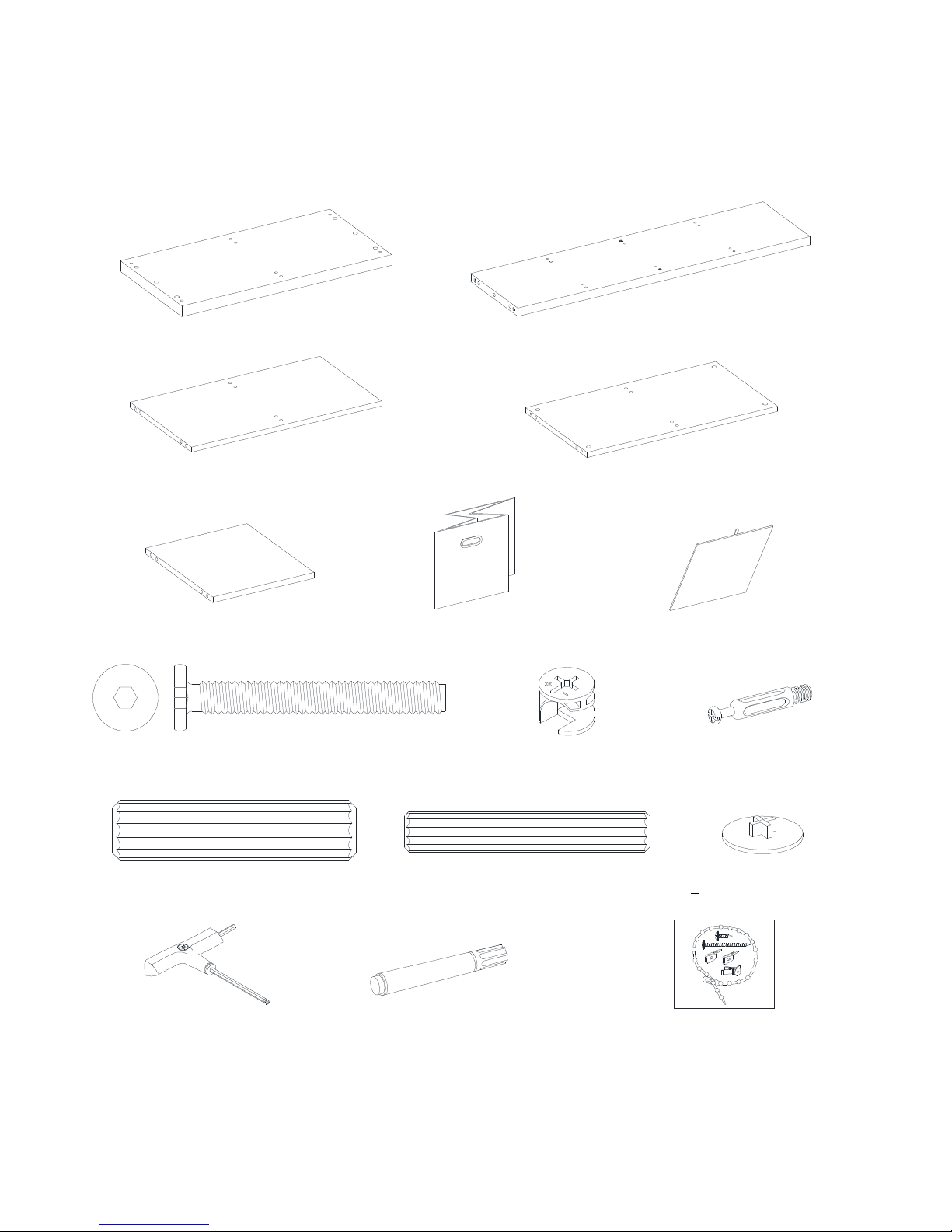
Parts and Hardware List
Please read completely through the instructions and verify that all listed parts and hardware are present
before beginning assembly.
A- Top/Bottom Panel (Qty. 2) B- Side Panel (Qty. 2)
C- Large Divider Panel (Qty. 2) D- Center Divider (Qty. 1)
(With Cam lock holes)
E- Small Divider Panel (Qty. 4) F- Storage Basket (Qty. 8) G- Basket Flooring (Qty. 8)
(1) ∅5/16" x 2-1/2" Bolt (2) Cam Lock (3) Cam Bolt
(Qty. 8+1 extra) (Qty. 4+1 extra) (Qty. 4+1 extra)
(4) ∅15 x 60 mm Wood Dowel (5) ∅10 x 60 mm Wood Dowel (6) Cam Lock Cover
(Qty. 12+1 extra)
(Qty. 40+2 extra)
(Qty. 4+1 extra)
T-handle Allen Wrench Touch-up Pen Tipping Restraint Hardware Kit (Qty. 1)
(Qty. 1) (Qty. 1) (Inside Plastic Bag)
Tools required: Allen wrench (provided), Phillips screwdriver and rubber mallet (not provided).
Page 4
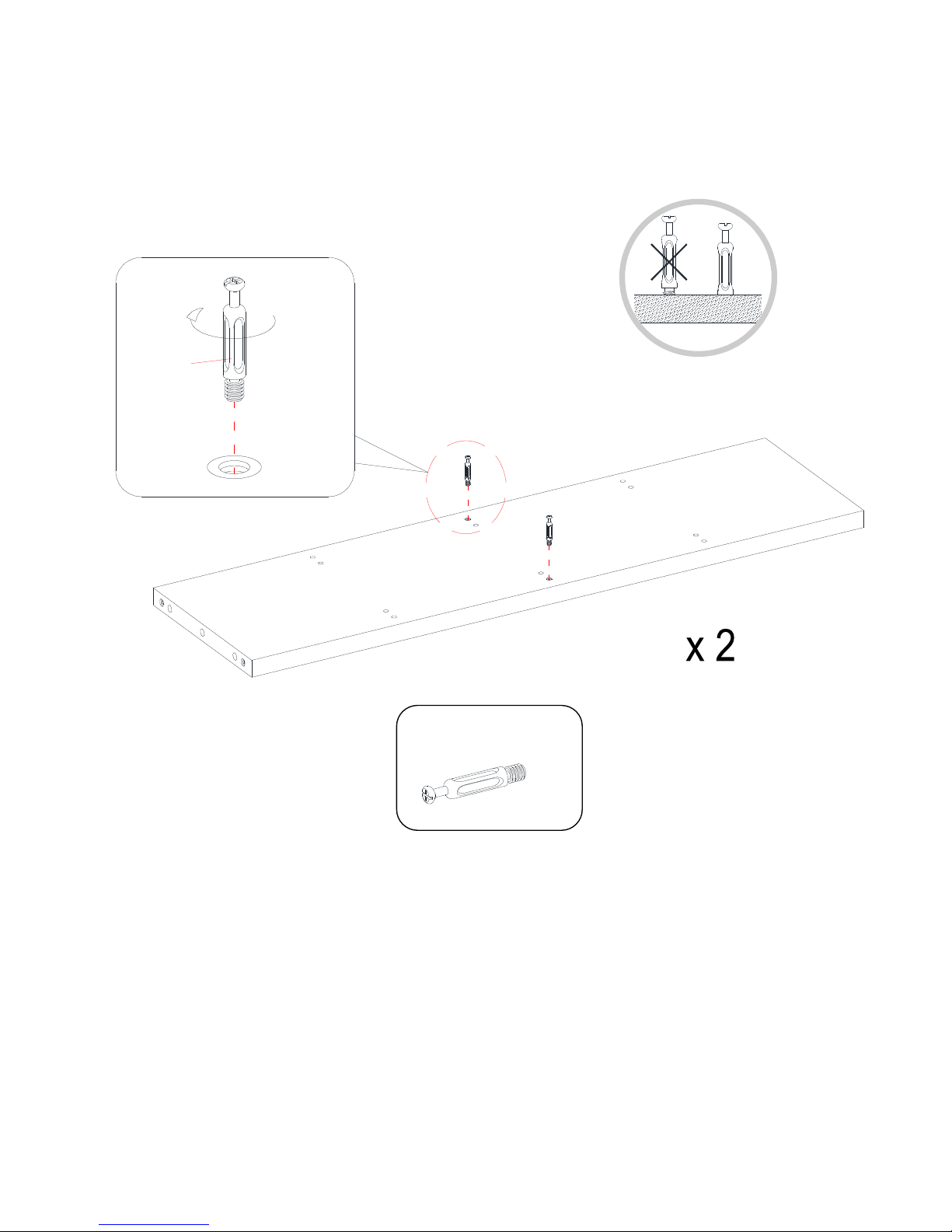
Assembly Instructions
1. Unpack the unit and confirm that you have all the hardware and required parts.
2. Lay the Side Panels (B) on a level and protected surface with the pre-drilled holes facing up. Screw two
Cam Bolts (3) into the plastic bushings included on the center of each Side Panel (B). Fully tighten with
a Phillips screwdriver.
Cam Bolt
(4 used in this step)
③
B
3
B
 Loading...