

Page 1
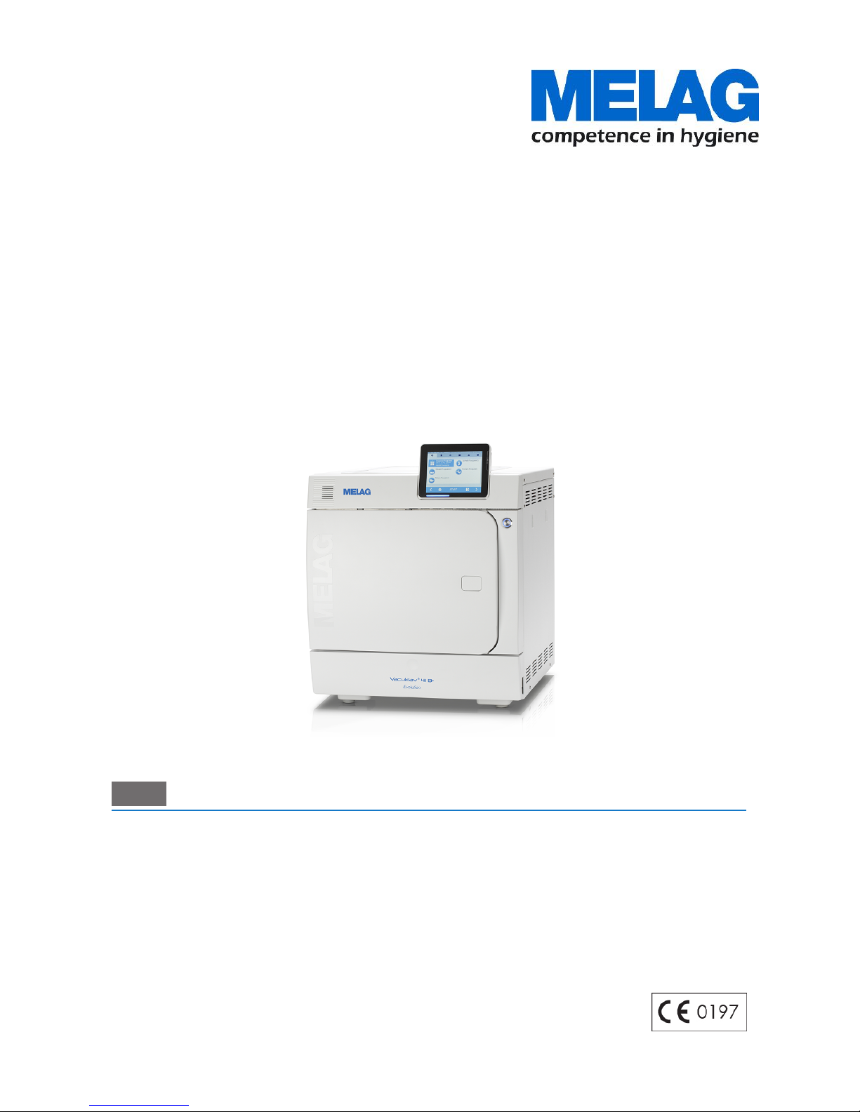
User Manual
Vacuklav® 41 B+ Evolution
Vacuklav® 43 B+ Evolution
Steam sterilizer
from software version 3.218
EN
Dear doctor,
We thank you for your confidence demonstrated by the purchase of this MELAG product. As an owner-run and operated
family concern founded in 1951, we have a long history of successful specialization in hygiene products for practicebased use. Our focus on innovation, quality and the highest standards of operational reliability has established MELAG
as the world’s leading manufacturer in the instrument treatment and hygiene field.
You, our customer are justified in your demand for the best products, quality and reliability. Providing "competence in
hygiene" and "Quality – made in Germany", we guarantee that these demands will be met. Our certified quality
management system is subject to close monitoring: one instrument to this end is our annual multi-day audit conducted in
accordance with ISO 13485 and ISO 9001. This guarantees that all MELAG products are manufactured and tested in
accordance with strict quality criteria.
The MELAG management and team.
Page 2

Page 3

Contents
Contents
1 General guidelines ...............................................................................................................................................................5
Symbols used.......................................................................................................................................................................5
Formatting rules ...................................................................................................................................................................5
Symbols on the device .........................................................................................................................................................5
2 Safety..................................................................................................................................................................................... 7
3 Performance specifications ................................................................................................................................................9
Intended use ........................................................................................................................................................................9
Sterilization procedure .........................................................................................................................................................9
Type of the feed water supply ..............................................................................................................................................9
Safety equipment .................................................................................................................................................................9
Overview of sterilization programs (class B) ......................................................................................................................11
Program sequences ...........................................................................................................................................................12
4 Description of the device................................................................................................................................................... 13
Scope of delivery................................................................................................................................................................13
Views of the device ............................................................................................................................................................14
Energy-saving key..............................................................................................................................................................15
Load mounts ......................................................................................................................................................................15
Colour-touch display ..........................................................................................................................................................16
LED status bar ...................................................................................................................................................................17
5 First steps ...........................................................................................................................................................................18
Setup and Installation.........................................................................................................................................................18
Feed water supply..............................................................................................................................................................18
Switching on the steam sterilizer........................................................................................................................................19
Opening and closing the door ............................................................................................................................................19
6 Loading the steam sterilizer..............................................................................................................................................22
Preparing the sterilization material.....................................................................................................................................22
Loading the steam sterilizer ...............................................................................................................................................23
7 Sterilization .........................................................................................................................................................................25
Important information regarding routine operation .............................................................................................................25
Selecting the program ........................................................................................................................................................26
Additional program options ................................................................................................................................................27
Starting the program ..........................................................................................................................................................28
Program run .......................................................................................................................................................................28
Manual program abort........................................................................................................................................................29
Program end ......................................................................................................................................................................31
Removing the sterilized equipment ....................................................................................................................................32
Storing sterile instruments..................................................................................................................................................33
8 Logging ...............................................................................................................................................................................34
Batch documentation .........................................................................................................................................................34
Output media......................................................................................................................................................................34
Outputting text logs automatically after program end (immediate output)..........................................................................36
Subsequent log output .......................................................................................................................................................37
Finding a log.......................................................................................................................................................................39
Page 4

Contents
9 Functional checks ..............................................................................................................................................................41
Vacuum test .......................................................................................................................................................................41
Bowie & Dick test ...............................................................................................................................................................42
10 Settings .............................................................................................................................................................................43
Logging ..............................................................................................................................................................................43
User administration ............................................................................................................................................................49
Formatting the CF card ......................................................................................................................................................51
Additional drying.................................................................................................................................................................51
Intelligent drying .................................................................................................................................................................52
Water supply ......................................................................................................................................................................52
Date & time ........................................................................................................................................................................53
Brightness ..........................................................................................................................................................................53
Volume ...............................................................................................................................................................................54
View ...................................................................................................................................................................................54
Key tone .............................................................................................................................................................................55
Screensaver .......................................................................................................................................................................56
Log printer MELAprint 42/44 ..............................................................................................................................................57
Label printer MELAprint 60 ................................................................................................................................................57
Sensitivity ...........................................................................................................................................................................57
Energy-saving mode ..........................................................................................................................................................57
11 Maintenance...................................................................................................................................................................... 59
Servicing intervals ..............................................................................................................................................................59
Cleaning .............................................................................................................................................................................59
Avoiding staining ................................................................................................................................................................61
Oiling the door spindle .......................................................................................................................................................61
Maintenance.......................................................................................................................................................................62
12 Pause times ......................................................................................................................................................................63
Frequency of sterilization ...................................................................................................................................................63
Operating pauses...............................................................................................................................................................63
Decommissioning...............................................................................................................................................................63
Emptying the double jacket ................................................................................................................................................63
Transport............................................................................................................................................................................64
Recommissioning after relocation ......................................................................................................................................65
13 Malfunctions .....................................................................................................................................................................66
Messages...........................................................................................................................................................................66
Warning and error messages.............................................................................................................................................67
14 Technical data ..................................................................................................................................................................77
15 Accessories and spare parts ..........................................................................................................................................78
Glossary .................................................................................................................................................................................79
Page 5
1 General guidelines
5
1 General guidelines
Please read this user manual carefully before commissioning the device. The user manual includes
important safety information. The functionality and value-retention of this device depends on the care
accorded to it. Please store these user manual carefully and in close proximity to your device. It represents
a component of the product.
Should the user manual no longer be legible, damaged or lost, please obtain a new copy from MELAG.
State the device type and your address in an e-mail.
The device type is specified on the type plate on the rear of the device.
Symbols used
Symbol Explanation
Indicates a dangerous situation, which if not avoided, could entail slight to lifethreatening injuries.
Draws your attention to a situation, which if not avoided, could result in damage to the
instruments, the practice fittings or the device.
Draws your attention to important information.
Formatting rules
Example Explanation
see Chapter 2 Reference to another text section within this document
UniversalProgram
Words or phrases appearing on the display of the device are marked as display text.
Symbols on the device
Manufacturer of the medical device
Date of manufacture of the medical device
Medical device serial number from the manufacturer
Article number of the medical device
Information about the chamber volume
Operating temperature of the device
Operating pressure of the device
Page 6
1 General guidelines
6
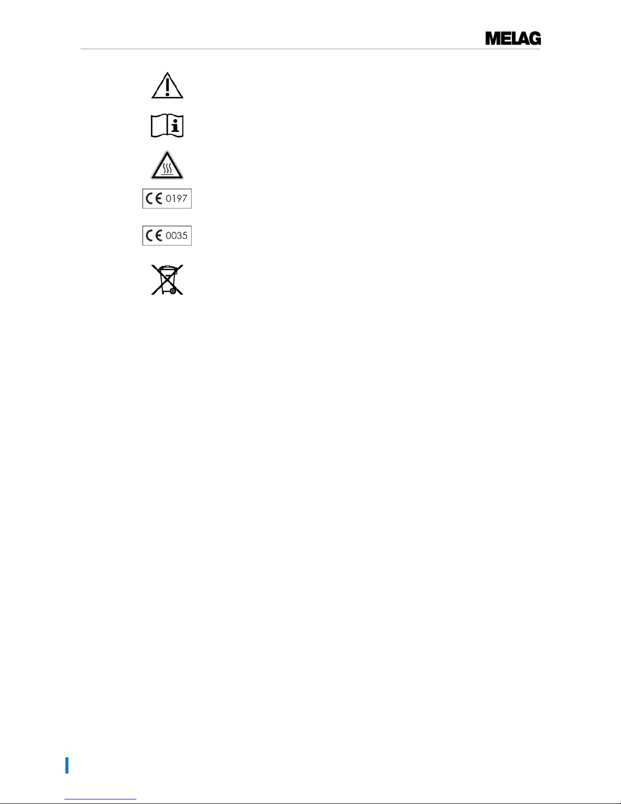
The user manual includes important safety information. Failure to comply with these
instructions can result in injury and material damage.
Please read this user manual carefully before commissioning the device.
Draws your attention to a hot surface. Should the fan fail, the cooling unit fins can
become hot.
In affixing this CE mark, the manufacturer declares that this medical product fulfils the
basic requirements of the Medical products directive. The four-digit number confirms that
this is monitored by an approved certification agency.
In affixing this CE mark, the manufacturer declares that this medical product fulfils the
basic requirements of the Pressure equipment directive. The four-digit number confirms
that this is monitored by an approved certification agency.
The device may not be disposed as domestic waste. The vendor is responsible for
appropriate disposal of the device - it must be delivered to the vendor to be disposed of.
In affixing this symbol, the manufacturer furthermore declares that he has satisfied all the
legal requirements pertaining to the release, redemption and environmentally sound
disposal of electric and electronic appliances.
MELAG devices are synonymous for long-term quality. When you eventually need to
decommission your MELAG device, we offer a special disposal service. Simply contact
your stockist.
Page 7

2 Safety
7
2 Safety
When operating the device, comply with the following safety instructions as well as those
contained in subsequent chapters. Use the device only for the purpose specified in these
instructions. Failure to comply with the safety instructions can result in injury and/or
damage to the device.
Qualified personnel
n As with the preceding instrument decontamination, the sterilization of instruments and textiles using
this steam sterilizer may only be carried out by competent personnel.
Set-up, installation and commissioning
n Check the device for any damage suffered during transport after unpacking.
n The device should only be set-up, installed and commissioned by MELAG authorized persons.
n The connections for electrical provision and water supply and effluent must be set-up by trained per-
sonnel.
n Use of the optional leak detector (water stop) minimizes the risk of water damage.
n In accordance with current VDE specifications, the device is unsuitable for operation in explosive at-
mospheres.
n Install and operate the device in a frost-free environment.
n The device is conceived for use outside the patient area. The device should be located a minimum of
1.5 m radius away from the treatment area.
n The documentation media (computer, CF card reader etc.) must be placed in such a way that they
cannot come into contact with liquids.
n Observe all the information contained in the technical manual during commissioning.
Power cable and power plug
n Only the power cable included in the scope of delivery may be connected to the device.
n The power cable may not be replaced by a cable determined to be insufficient.
n Comply with all legal requirements and locally-specified connection conditions.
n Never operate the device if the plug or power cable are damaged.
n The power cable and plug should only be replaced by authorized personnel.
n Never damage or alter the power plug or cable.
n Never unplug by pulling on the power cable. Always take a grip on the plug.
n Ensure that the power cable does not become jammed in.
n Never lead the cable along a source of heat.
n Never fix the power cable with sharp objects.
Double-jacket steam generator
n The steam sterilzer remains pressurized for a long time after being switched-off. Check the pressure
display of the manometer below on the front of the device.
Decontamination and sterilization
n Follow the manufacturer instructions of your textile articles and instruments regarding their decontam-
ination and sterilization.
n Observe the relevant standards and directives for the decontamination and sterilization of textiles and
instruments, e.g. RKI [Robert Koch Institute] and DGSV [German Society for Sterile Supply].
n Only ever use packaging material and systems which have been approved by their manufacturer for
steam sterilization (consult the manufacturer’s instructions).
Page 8

2 Safety
8
Program termination
n Please observe that depending on the time of the program abort, opening the door following a pro-
gram abort can lead to hot steam leaving the chamber.
n Depending on the time of the program abort, it is possible that the load is unsterile. Observe the clear
instructions shown on the display of the steam sterilizer. If necessary, sterilize the affected objects
after rewrapping.
Removing the sterilized equipment
n Never use force to open the door.
n Use a tray jack to remove the tray. Never touch the sterilized items, the chamber or the door with un-
protected hands. The components are hot.
n Check the packaging on the sterilized equipment for damage when removing it from the steam steril-
izer. Should the packaging be damaged, re-pack the sterilization material and re-sterilize it.
Transport and storage
n Store and transport the device in a frost-free environment.
n The device should always be carried by two people.
n Use suitable carrying straps to carry the device.
Maintenance
n Have the maintenance done only by authorized persons.
n Maintain the specified servicing intervals.
n Only original MELAG spare parts may be used.
Malfunctions
n Should the device issue the same malfunction message repeatedly, turn off the device
and if necessary, inform your stockist.
n Only have the device repaired by authorized persons.
Page 9
3 Performance specifications
9
3 Performance specifications
Intended use
This steam sterilizer is designed for application in a medical context, e.g. General Practitioners and dental
practices. According to DIN EN 13060, this steam sterilizer is a Class B sterilizer. As a universal steam
sterilizer, it is suited to highly-demanding sterilization tasks. It can be used to sterilize instruments with a
narrow lumen and transfer instruments - both wrapped or unwrapped - and large quantities of textiles.
WARNING
Any attempt to sterilize liquids can result in a delay in boiling. This can result in damage
of the steam sterilizer and burns.
n Never use this steam sterilizer to sterilize any fluids. It is not licensed for the sterilization of
fluids.
Sterilization procedure
The steam sterilizer sterilizes on the basis of the fractionated vacuum procedure. This guarantees the
complete and effective wetting/penetration of the sterilization material with saturated steam.
This procedure enables the sterilization of loads common to a doctor's practice.
The steam sterilizer uses the double-jacket technology to generate the sterilization steam, i.e. the steam
sterilizer is fitted with a separate steam generator combined with a double-walled sterilization chamber.
After heating, steam is held constantly available in the double-jacket. This gives the walls of the
sterilization chamber a defined temperature and protects the sterilization chamber from overheating. This
especially effective procedure supports the quick evacuation of the air from the sterilization chamber, the
sterilization packaging and instrument cavities. This permits the sterilization of large quantities of
instruments or textiles directly one after each other, thereby achieving excellent drying results.
Type of the feed water supply
The steam sterilizer works with a one-way feed water system. This means that it uses fresh feed water (i.e.
demineralized or distilled water) for every sterilization procedure. The quality of the feed water is subject to
permanent monitoring via integrated conductivity measurement. If combined with careful preparation of the
instruments, this serves largely to prevent stain accretion on the instruments and soiling of the steam
sterilizer.
Safety equipment
Internal process monitoring
An process evaluation system is integrated in the electronics of the steam sterilizer. It compares the
process parameters (such as temperature, time and pressure) during a program run. It monitors the
parameters in terms of their threshold values during control and regulation and guarantees safe and
successful sterilization. A monitoring system checks the device components of the steam sterilizer for their
functionality and their plausible interaction. If one or more parameters exceeds pre-determined threshold
values, the steam sterilizer issues warning or malfunction messages and if necessary, aborts the program.
In the case of a program abort, follow the instructions on the display.
The steam sterilizer uses an electronic parameter control. This enables the steam sterilizer to optimize the
total operating time of a program in dependence on the load.
Door mechanism
The steam sterilizer constantly checks pressure and temperature in the sterilization chamber and prevents
the door from being opened when over-pressure has built up in the chamber. The motor-driven automatic
door locking mechanism opens the door slowly by turning the locking spindle. This also holds the door
Page 10

3 Performance specifications
10
whilst it opens. Pressure compensation will have been performed by the time that the door is completely
open, even following pressure differences.
Quantity and quality of the feed water
The quantity and quality of the feed water is automatically checked before every program start.
Page 11
3 Performance specifications
11
Overview of sterilization programs (class B)
The results in this table show which inspections were performed on the steam sterilizer. The marked field
shows compliance with all the applicable sections of the standard DIN EN 13060.
Type tests Universal-
Program
QuickProgram B
QuickProgram S
GentleProgram
PrionProgram
Program type in
accordance with DIN EN
13060
Type B Type B Type S Type B Type B
Dynamic pressure test of
the sterilization chamber
X X X X X
Air leakage X X X X X
Empty chamber test X X X X X
Solid load X X X X X
Porous partial load X -- -- X X
Porous full load X -- -- X X
Simple hollow body
(Hollow body B)
X X X X X
Product with narrow
lumen (Hollow body A)
X X -- X X
Single wrapping X X -- X X
Multiple wrapping X -- -- X X
Drying solid load X X X X X
Drying, porous load X -- -- X X
Sterilization temperature 134 °C 134 °C 134 °C 121 °C 134 °C
Sterilization pressure 2.1 bar 2.1 bar 2.1 bar 1.1 bar 2.1 bar
Sterilization time 5:30 min. 5:30 min. 03:30 min. 20:30 min. 20:30 min.
X = Complies with all applicable sections of the standard DIN EN 13060
Page 12
3 Performance specifications
12
Program sequences
Regular sterilization program
A program runs in three phases, the air removal; sterilization; and drying phase. After program start, you
can follow the program run on the display. It shows the chamber temperature and pressure as well as the
time until the end of sterilization / the drying.
Program phase Description
1. The air removal
phase (fractionation)
The air removal phase comprizes the conditioning and the evacuation phase.
During conditioning, steam is repeatedly injected into the sterilization chamber to
generate over-pressure. The mixture of air and steam is then removed
repeatedly (evacuation). This procedure is also called the fractionated prevacuum procedure.
2. Heating phase The heating phase follows the air removal phase. The continued steam
admittance into the chamber leads to an increase in pressure and temperature
which continues until the program-specific sterilization parameters have been
reached.
3. Sterilization phase If the pressure and temperature correspond to the program-dependent nominal
values, the sterilization phase begins. The sterilization time is indicated on the
display.
4. Pressure release The end of the sterilization phase is followed by pressure release of the
sterilization chamber.
5. Drying phase The sterilization material is dried using a vacuum (vacuum drying). The drying
phase begins after the pressure release. Upon program end, the chamber is
filled with sterile air via the air filter and adjusted to the ambient pressure.
6. Ventilation Once the program has come to an end, the chamber pressure is adapted to the
ambient pressure. The corresponding display notification "ventilation" is
displayed.
Vacuum test
The vacuum test serves measurement of the leakage rate. No real sterilization is performed. The test is
performed with a cold, dry and unloaded device.
Program phase Description
1. Air removal phase
(evacuation)
The chamber is evacuated until the pressure for the vacuum test has been
reached.
2. Equilibration time An equilibration time of five minutes will follow.
3. Measurement time The measurement time amounts to ten minutes. The pressure increase within
the chamber is measured during the measurement time. The evacuation
pressure and the equilibration time or measuring times are shown on the
display.
4. Test end The display shows the test results, the batch number, the total number of
batches and the leakage rate
Page 13

4 Description of the device
13
4 Description of the device
Scope of delivery
Please check the scope of delivery before setting up and connecting the device.
Standard scope of delivery
▪ Vacuklav 41 B+ oder Vacuklav 43 B+
▪ User manual
▪ Usage instructions for the mounts
▪ Manufacturer's inspection report including declarations of conformity
▪ Guarantee
▪ Technical manual
▪ Record of installation and setup
▪ Mounts for trays and cassettes
▪ Tray lifter
▪ Power cable
▪ 2x cover caps for the fore device feet
▪ 2x mounts for the water treatment unit MELAdem
▪ 4x cover caps for niches for mounts in the side wall
▪ Allen key to open the door in an emergency
▪ TORX key for removing the carrying strap
▪ 1x hose for emptying the interior water storage tank
▪ Oil for door lock bushing
Optional
▪ Trays
▪ Standard tray cassettes and lifter
▪ MELAstore-Trays
▪ MELAstore-Boxes
▪ Additional mounts
▪ MELAflash CF-Card
▪ MELAflash CF card reader
▪ Wall bracket for Flex display
Page 14
4 Description of the device
14
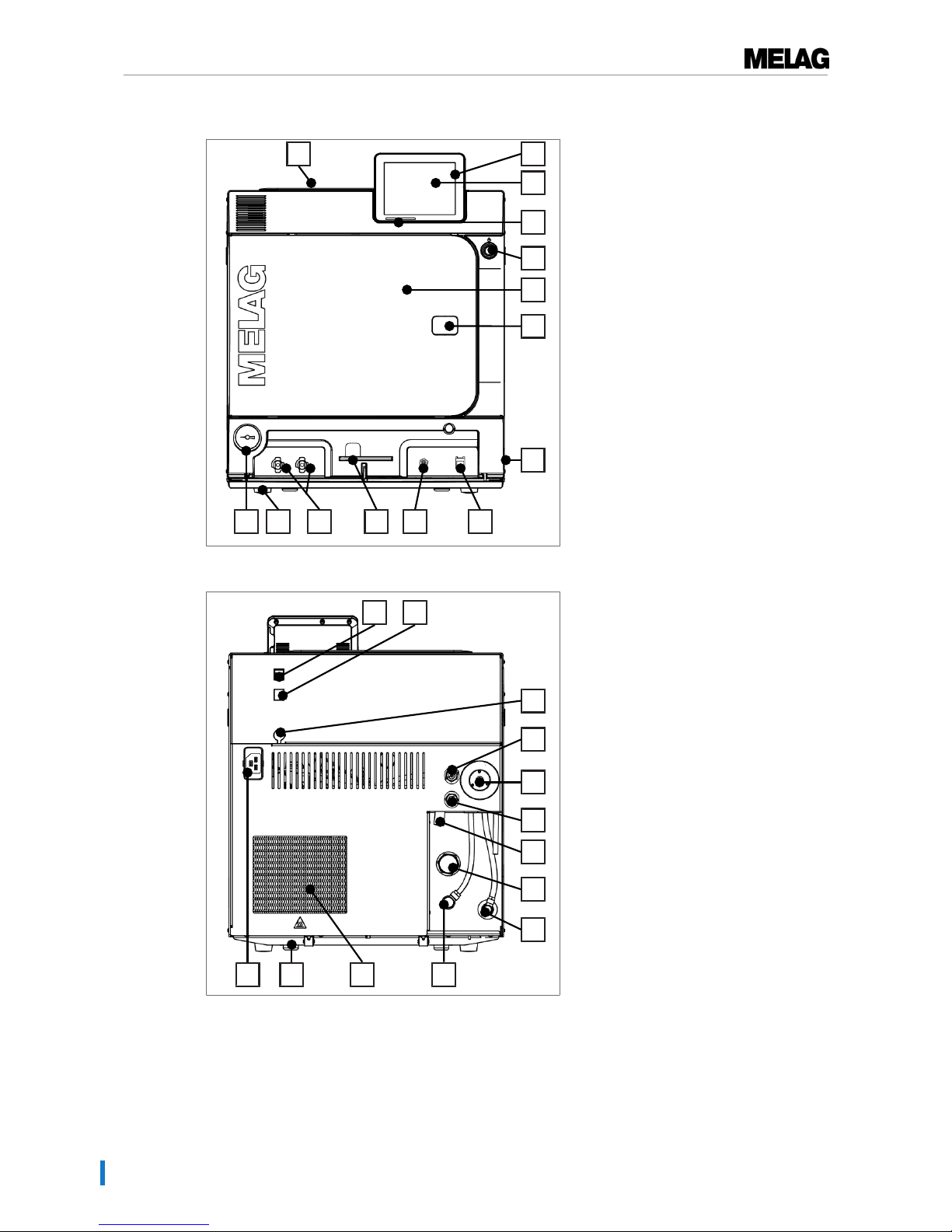
Views of the device
8
14 13 10 9
7
4
3
2
5
12 11
6
1
Fig.1 : View from front
1 Tank lid of the internal storage
tank
2 CF card slot
3 Colour touch-display
4 LED status bar
5 Energy-saving key
6 Door (swings open to the left)
7 Opening for door opening in an
emergency*)
8 Power switch (covered,
accessible from the side)
9 Ethernet connection
10 Overheat control reset button
11 Allen key 5 mm to open the door
in an emergency
12 Quick coupling for emptying the
storage tank
13 Front device foot (adjustable)
14 Manometer for pressure display
on the double-jacket steam
generator
*)
*) behind cover
22
23
24
20
16
19
15
18
272126 25
17
Fig.2 : View from rear
15 Ethernet connection
16 Ethernet connection, optional
(upgradeable)
17 Optional connection of a Flex
display
18 Spring safety valve chamber
19 Sterile filter
20 Spring safety valve double jacket
21 Emergency overflow
22 One-way discharge
23 Feed water inflow (swivel screw
connection for Ø8x1 hose,
alternative straight)
24 Connection pressure release
25 Cooler
26 Rear device foot (fixed)
27 Power cable connection
Page 15
4 Description of the device
15
35 34 3233
29
30
28
31
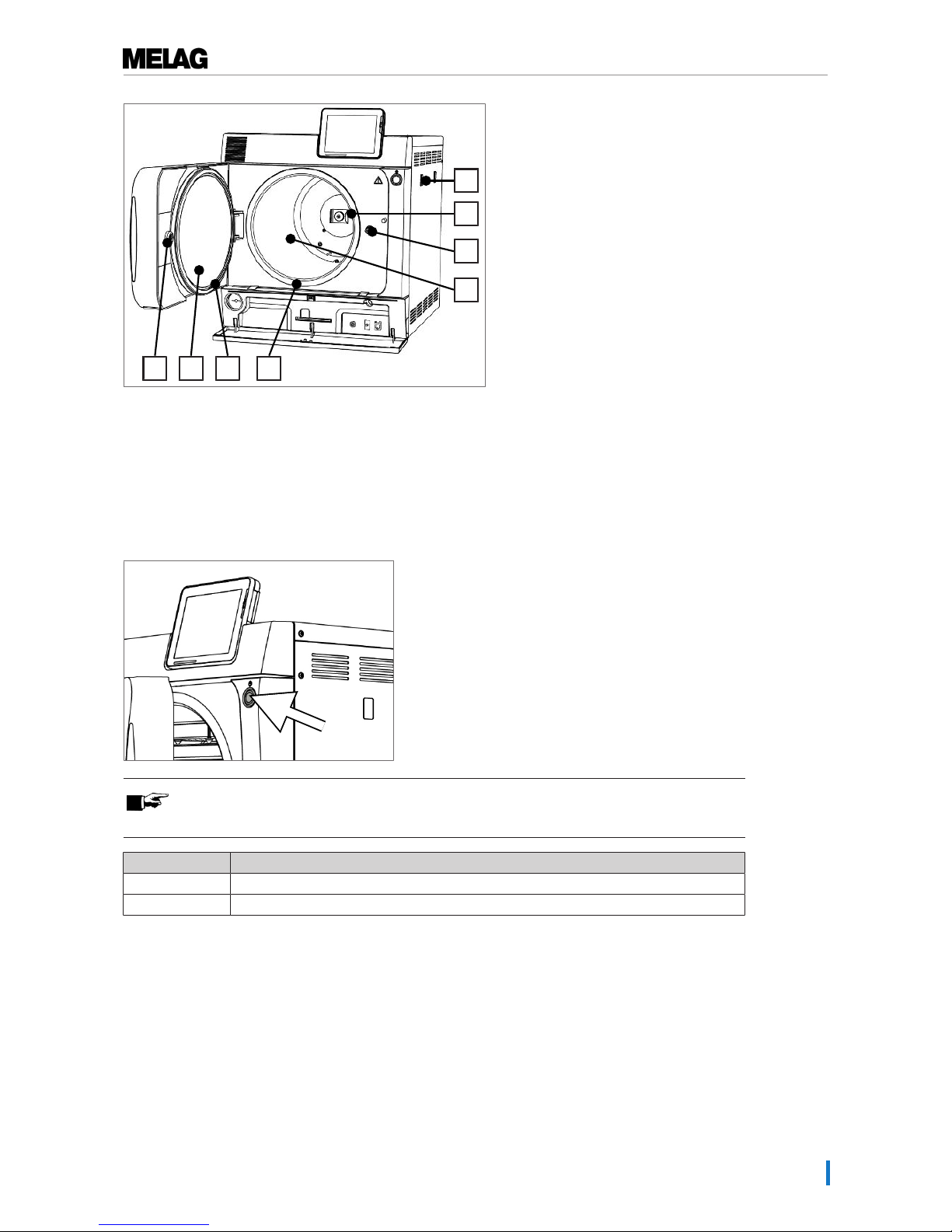
Fig.3 : View from front, door open
28 Mount for the water treatment
unit MELAdem
29 Spring clip for fixing the mount
“Plus”
30 Door spindle
31 Sterilization chamber
32 Chamber sealing face
33 Door seal
34 Round blank
35 Bushing
Energy-saving key
Pressing the energy-saving key activates the energy-saving mode and switches off the display. The
double jacket will not be heated until the next program start. This corresponds to waiting time 2, see also
Settings [}page 43], Energy-saving mode [}page 57].
Pressing the energy-saving key again will switch the display back on.
PLEASE NOTE
The energy-saving mode can not be activated during a program run.
State Meaning
Lighted The energy-saving mode can be activated.
Not lighted The energy-saving mode can not be activated.
Load mounts
The steam sterilizer is always delivered with a mount for holding trays or cassettes. Detailed information
regarding the various mounts, their combinability with various load holders and their application can be
found in the operating manual of the mounts.
Page 16
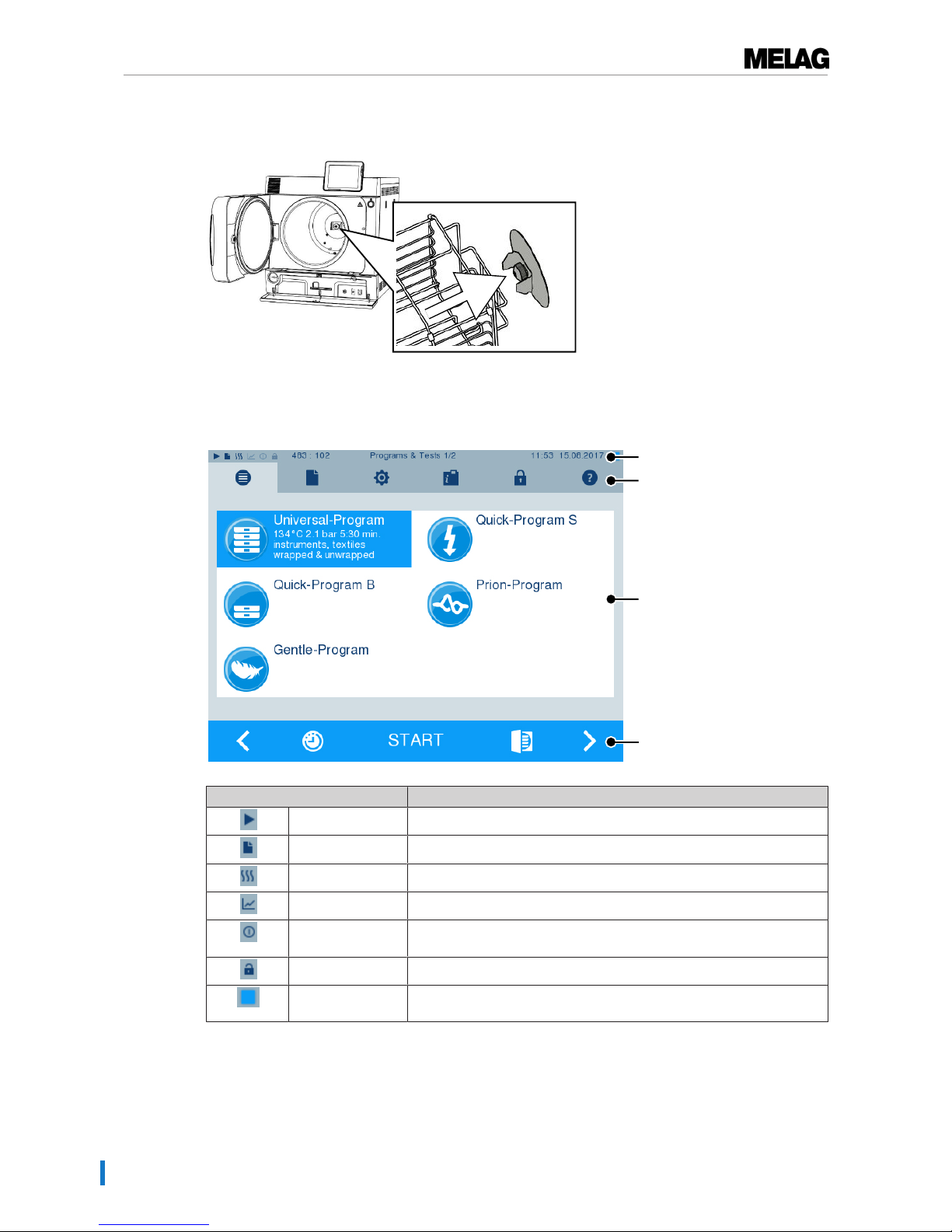
4 Description of the device
16
A spring clip is located on the rear panel of the sterilization chamber to fix the mount. When using a “Plus”
mount, slide the mount into the sterilization chamber to its fullest extent, until the mount snaps into the
spring clip.
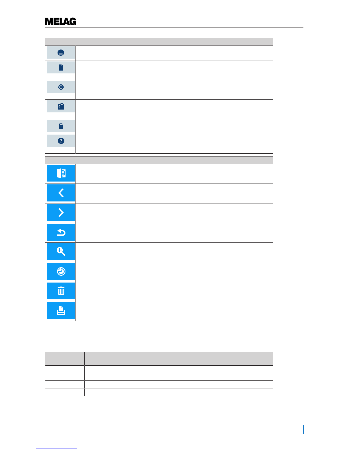
Colour-touch display
The operating panel consists of a colour 5 inch touch display.
Status bar
Menu bar
Main area
Action bar
Symbols in the status bar Meaning
Program/tests Indicates whether a program/test is running
Immediate output Indicates whether immediate output is activated/deactivated
Additional drying Indicates whether additional drying is activated/deactivated
Graphic logs Indicates whether the graphic log recording is activated/deactivated
Energy-saving
mode
Indicates whether the steam sterilizer is currently in energy-saving
mode
Service area Indicates whether a service technician is logged-in to the service area
CF card status Indicates whether a CF card has been inserted and whether a reading
or writing action is in process.
Page 17
4 Description of the device
17
Symbol in the menu bar Meaning
Program/tests Lists all sterilization programs and tests e.g. Vacuum test, Bowie &
Dick- test etc.
Log output Here you can display the entire log list or the list of logs from a
restricted time e.g. the day, month etc. You can also delete specific log
types and logs.
Settings Here you can perform various settings such as date and time,
brightness etc. It also enables one-time setting of the "standard"
logging settings regarding log output.
Info/status window Displays information regarding the software version and device data
e.g. total number of batches, maintenance counter, log settings, log
memory and further technical values.
Service area Only for technicians
Help menu Depending on the window selected and the operating situation, gives
information regarding operation or the function of the window currently
selected.
Symbols in the action bar Meaning
Door open Opens the door of the steam sterilizer
Back Returns to the previous window
Forwards Navigates to the next window
Cancel/return
without saving
Navigates to the superordinate menu, leaves the window without
saving
Zoom (+) Displays further details such as further values after a completed
program
Start time preselection
Navigates to the "Start time pre-selection" menu
Delete Deletes logs from the internal log memory / deletes the log printer or
label printer stored as standard
Search Searches for label printer(s)/log printer(s)
LED status bar
The status bar on the lowest edge of the display indicates different situations with various colours
Colour of the
LED
Meaning
Blue Standby, program running, drying has not yet begun
Green Drying running, program completed successfully
Yellow Warning message, software update is running
Red Malfunction message, program not completed successfully
Page 18
5 First steps
18
5 First steps
Setup and Installation
PLEASE NOTE
Comply with the specifications of the technical manual during set-up and installation.
This contains all building-side requirements.
Record of installation and set-up
The responsible stockist is to complete the record of installation and setup as proof of the correct setup,
installation and commissioning. A copy is to be sent to MELAG. This is a constituent part of any guarantee
claim.
Feed water supply
The steam sterilizer requires the use of distilled or demineralized water water, known as feed water.
DINEN13060 requires that feed water be used in accordance with the guideline values in appendixC.
The steam sterilizer requires c. 3 L feed water for the first filling of the steam generator.
The feed water supply is effected either via the internal feed water tank or via a separate water treatment
unit (e.g. MELAdem 40/MELAdem 47). The used feed water, so called waste water is either collected in
the internal storage tank on the waste water side (left) and emptied manually or disposed of automatically
via a building-side waste water connection.
NOTICE
When connecting an external feed water supply it is necessary to connect an external
waste water outflow as well.
There is a risk that hot waste water might run through the emergency overflow.
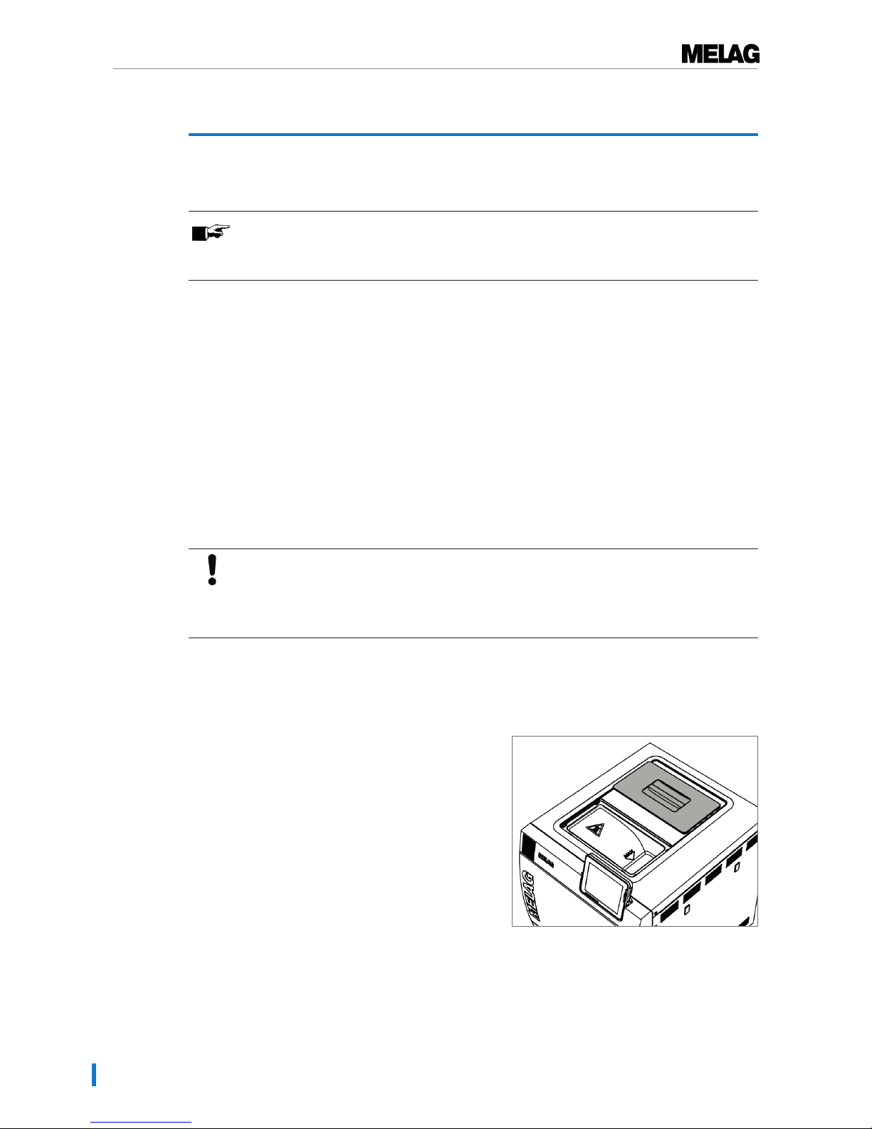
Using the internal water storage tank
The internal storage tank holds max. 5 litres. This volume of feed water is sufficient for up to 7 sterilization
runs.
1. To fill the storage tank with fresh feed water remove
the lid and fill the right-hand chamber of the storage
tank with fresh feed water up to the MAX mark.
2. Set the feed water supply in the display
toINTERNAL, see settings, Water supply [}page
52].
Page 19
5 First steps
19
Switching on the steam sterilizer
ü
The steam sterilizer is connected to the electricity supply.
ü
The feed water supply is secure. The steam sterilizer requires c. 3 L feed water for the first filling of the
steam generator.
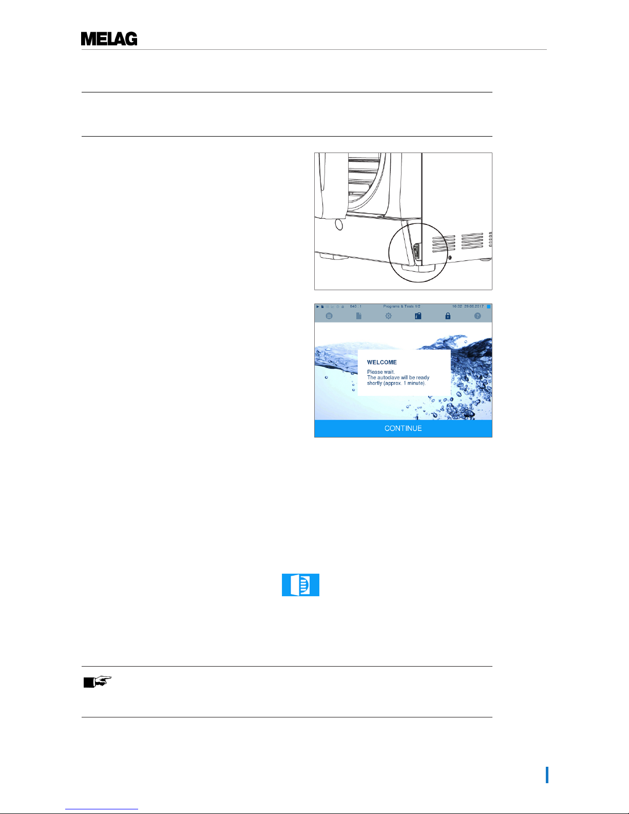
1. Switch on the steam sterilizer at the power switch.
2. When the welcome screen appears, press
CONTINUE. The display switches to the main menu.
The feed water level is checked and pre-heated immediately after activation.
Depending on the device type, it requires a heat-up time of c. 9 - 13 minutes after being switched on. This
time is required for the pre-heating of the double-jacket steam generator.
Opening and closing the door
The steam sterilizer is fitted with a motor-driven automatic door locking mechanism with a threaded
spindle. Entry on the display is only possible when the door is closed.
Opening the door
The door is opened by pressing on the door symbol on the display.
When opening the door, comply with the following instructions, so as to ensure faultless operation of the
door locking mechanism.
u Never use force to open the door.
u Do not pull vigorously at the door to open it. The door opens automatically.
PLEASE NOTE
The door is to be left open only whilst loading and unloading the steam sterilizer.
Keeping the door closed saves energy.
Page 20
5 First steps
20
Closing the door
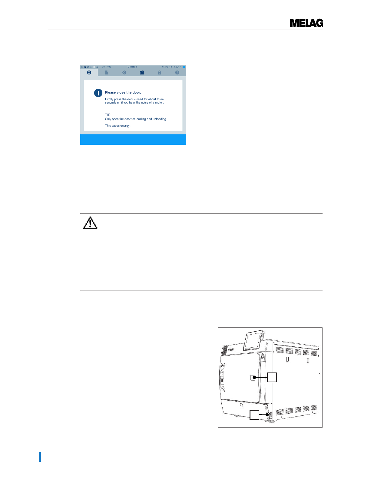
To close the door, press it firmly inwards until the automatic door lock engages. After the door has been
closed, the display returns to the program menu. The door is locked pressure-tight upon program start.
When closing the door, comply with the following instructions to guarantee faultless operation of the door
locking mechanism:
u Do not exert too little pressure when pushing the door closed.
u Hold the door closed for min. 3 seconds until the door lock engages.
u Never slam the door.
Manual door emergency-opening
WARNING
Danger of burns from hot steam. Where necessary e.g. during a running program or
immediately after the end of a program, steam can be emitted from the sterilization
chamber upon opening the door.
This could result in burns.
n Should steam be issued from the rear of the device after its deactivation, wait until it has
finished. Wait a further 5 minutes before opening the door.
n Stand to one side of the door and maintain sufficient distance.
n Allow the sterilization chamber to cool before removing the load.
In emergency situations e.g. power outage, the door can be opened in the following fashion:
1. If the steam sterilizer is still switched on, switch it
off at the power switch (pos. a).
2. Remove the cover cap in order to facilitate emergency
door-opening (pos. b) by pushing out (e.g. with a
small narrow slotted screwdriver).
b
a
Page 21
5 First steps
21
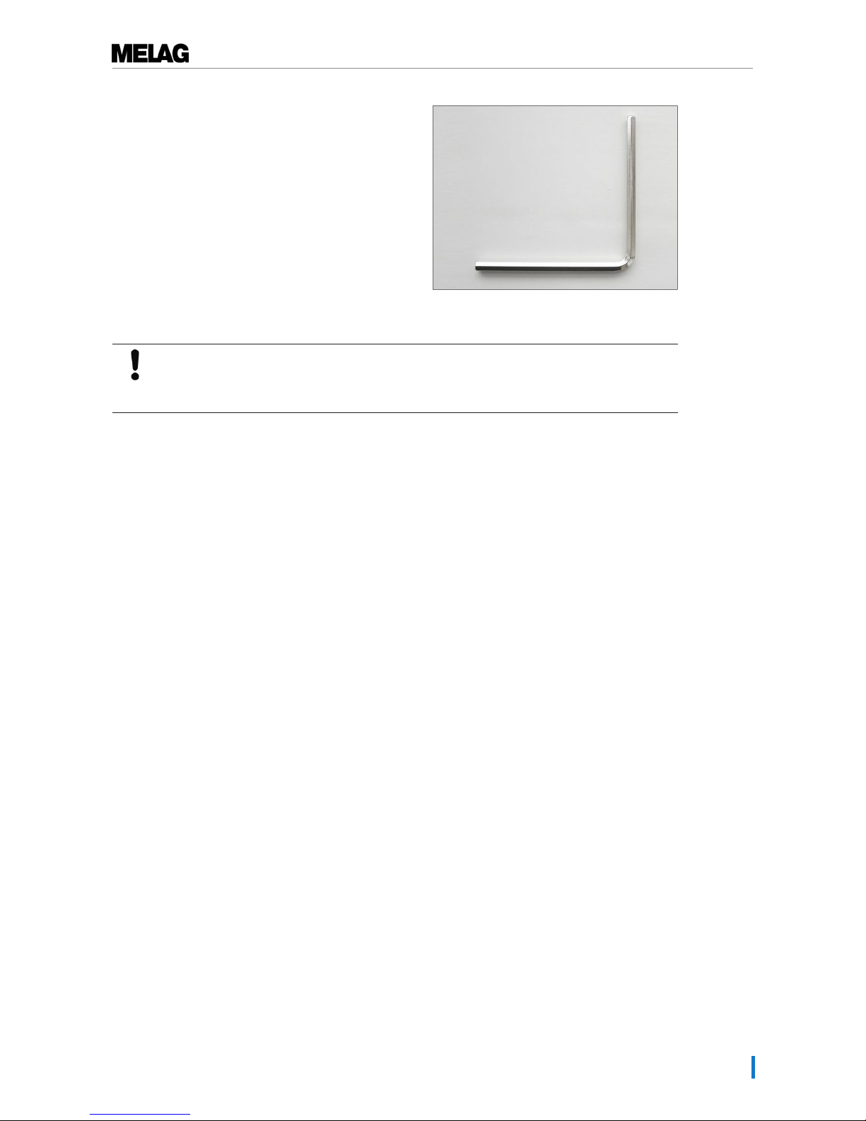
3. Insert the 5 mm Allen key included in the scope of
delivery in the opening. The Allen key can be stored in
the bracket behind the service hatch intended for this
purpose.
4. Turn the Allen key to open the door in a clockwise
direction.
NOTICE
Do not open the door as long as the Allen key is inserted. This may cause damage to the
plastic casing.
5. Remove the Allen key.
6. Open the door and return the cover cap.
Page 22
6 Loading the steam sterilizer
22
6 Loading the steam sterilizer
Preparing the sterilization material
Cleaning and disinfection must always have been performed before sterilization. Only in this way is it
possible to guarantee the subsequent sterilization of the sterilization material. The materials used, the
cleaning fluid and treatment procedures used are of decisive significance.
Decontaminating the instruments
WARNING
The incorrect decontamination of instruments could result in any dirt residue being
loosened by the steam pressure during sterilization.
The use of unsuitable care agents e.g. water repellent agents or oils impermeable to
steam could result in unsterile instruments. This represents a danger to the health of
both patients and yourself.
NOTICE
The presence of residual disinfection and cleaning fluids results in corrosion.
This could result in increased maintenance requirements and a restriction of the steam
sterilizer function.
Please ensure the following when treating used and brand-new instruments:
u Follow both the instrument manufacturer’s instructions regarding decontamination and sterilization and
comply with the relevant standards and directives e.g. from the BGV A1, RKI and DGSV.
u Clean the instruments exceptionally thoroughly e.g. using an ultrasonic device or washer-disinfector.
u Rinse the instruments after washing and disinfecting, where possible with de-mineralized or distilled
water and then dry the instruments thoroughly with a clean, non-fuzzing cloth.
u Use only those care agents suitable for steam sterilization. Consult the manufacturer of the care
agents. Do not use any water repellent agents or oils impermeable to steam.
u When using ultrasound devices, care equipment for handpieces and washer-disinfectors, please
comply with the manufacturer’s treatment instructions.
Treating textiles
WARNING
The incorrect decontamination of textiles, e.g. a textile package can prevent steam
penetration and/or produce poor drying results. The textiles could not be sterilized.
This could endanger the health of patient and practice team.
Please comply with the following points when treating textiles and putting the textiles in sterilization
containers:
u Comply with both the manufacturer's instructions of the textiles regarding treatment and sterilization as
well as the relevant standards and directives e.g. from the RKI and DGSV.
u Arrange the folds in the textiles parallel to each other.
u Stack textiles vertically wherever possible and not too closely together in the sterilization container.
This enables the development of flow channels.
u Retain the vertical stacking system when packing textiles in the sterilization container.
Page 23
6 Loading the steam sterilizer
23
u If textile packages do not remain together, wrap the textiles in sterilization paper.
u Only ever sterilize dry textiles.
u The textiles may not be permitted to come into direct contact with the sterilization chamber; otherwise
they will become saturated with condensate.
Loading the steam sterilizer
Effective sterilization and good drying is only possible if the steam sterilizer has been loaded correctly.
Ensure the following during loading:
u Insert trays or cassettes in the chamber only with their appropriate mount.
u Use perforated trays such as those from MELAG. Only in this way can condensate drain off. The use
a non-perforated base or half-shell to accommodate the sterilization material can result in poor drying
results.
u The use of paper tray inserts can also result in poor drying results.
u Wherever possible, please ensure the separate sterilization of textiles and instruments in separate
sterilization containers or sterilization packaging. This leads to better drying results.
Packaging
Only ever use packaging materials and systems (sterile barrier systems) which fulfil the standard
DINENISO11607-1. The correct use of suitable packaging is important in achieving successful
sterilization results. You can use re-usable rigid packaging systems such as e.g. standard tray cassettes or
soft packaging such as transparent sterilization packaging, paper bags, sterilization paper, textiles or
fleece.
Closed sterilization containers
CAUTION
The use of unsuitable sterilization containers results in insufficient steam penetration
and even failure of the sterilization. This can also prevent condensate drain-off.
This produces poor drying results. This can result in unsterile instruments and thus
endanger the health of patient and practice team.
CAUTION
Incorrect stacking of the sterilization containers can result in the dripping condensate
being unable to drain off to the chamber floor. This can saturate sterilization material
directly underneath it.
This produces poor drying results. This can result in unsterile instruments and thus
endanger the health of patient and practice team.
n Do not cover the perforations when stacking the sterilization containers.
Please comply with the following when using closed sterilization containers for sterilization material:
u Use aluminium sterilization containers. Aluminium retains and conducts heat and thus accelerates
drying.
u Closed sterilization containers must be either perforated or have a valve on at least one side -
optimally the bottom. MELAG sterilization containers fulfil the requirements for successful sterilization
and drying.
u The perforations of one-sided perforated sterilization containers should be at the top of any containers
as with MELAstore-Boxes.
u Wherever possible, please ensure that sterilization containers are only stacked on top of those of
identical size, so that the condensate can run down their sides.
u Ensure that the perforations are not covered when stacking the containers.
Page 24

6 Loading the steam sterilizer
24
Soft sterilization packaging
Soft sterilization packaging can be used in both sterilization containers and on trays. Please comply with
the following when using soft sterilization packaging e.g. MELAfol:
u Arrange soft sterilization packaging in a perpendicular position and at narrow intervals.
u Do not place multiple soft sterilization packages flat on top of each other on a tray or in a container.
u If the seam seal tears during sterilization, this could be caused by the choice of undersized packaging.
Should this not be the case, re-pack the instruments and sterilize them again.
u Should the seam seal rip during sterilization, extend the sealing pulse on the film sealing device or
make a double seam.
Multiple wrapping
The steam sterilizer works with a fractionated vacuum procedure. This permits the use of multiple
wrapping.
Mixed loads
Please observe the following when sterilizing mixed loads
u Always place textiles at the top
u Place the sterilization containers at the bottom
u Place unwrapped instruments at the bottom
u Place the heaviest loads at the bottom
u Place transparent sterilization packaging and paper bags at the top - except in combination with
textiles. In this case, place them at the bottom.
u Place transparent sterilization packages on their edge wherever possible and with the paper side
facing downwards.
Page 25

7 Sterilization
25
7 Sterilization
Important information regarding routine operation
Please comply with the recommendations issued by the Robert-Koch-Institute (RKI) and the information
contained in DIN 58946-7 (Germany).
Manufacturer's recommendation for the routine operation of Class B steam sterilizers
1
When is it necessary to
make checks?
How should the checks be made?
Once per working day ▪ Visual check of the door seal and the door seal for damage.
▪ Check the operating agents (electricity, feed water and water
connection if necessary).
▪ Check the documentation media (printer paper / computer / network)
We recommend performing the steam penetration test with
MELAcontrol/MELAcontrol PRO in the Universal-Program (test
system in accordance with DIN EN 867-5).
Once a week ▪ Vacuum test
Tip: In the mornings before starting work - the steam sterilizer must
be cold and dry.
Batch-related tests With “Critical B” instruments:
▪ MELAcontrol/MELAcontrol PRO must be used as batch control with
every sterilization cycle.
With “Critical A” instruments:
▪ The process indicator (type 5 in accordance with DIN EN ISO 11140)
must be used as batch control with every sterilization cycle.
With “Critical A + B” instruments:
▪ MELAcontrol/MELAcontrol PRO must be used as batch control with
every sterilization cycle.
This simplifies the working procedure and increases security. You can
omit the daily steam penetration test with MELAcontrol/MELAcontrol PRO
(see above). The use of another test system in accordance with DIN EN
867-5 is possible. The number of the available test systems means that
MELAG is not able to provide technical support when using a different
system.
The indicator test strips used need not be stored.
PLEASE NOTE
The results of the tests must be documented.
1)
in accordance with the current recommendations from the Robert-Koch-Institut
Page 26
7 Sterilization
26
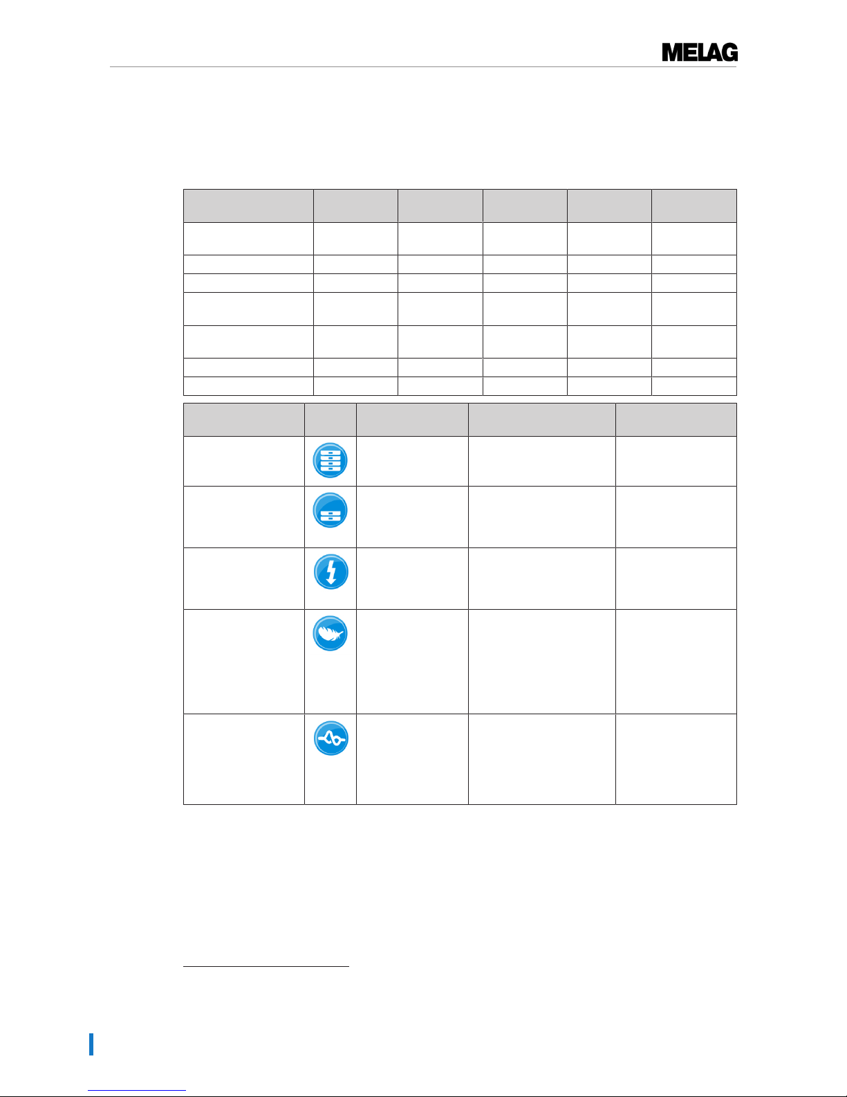
Selecting the program
Now select the sterilization program according to how and whether the sterilization material is packed. It is
also necessary to take into account the temperature resistance of the sterilization material. All sterilization
and additional programs are displayed in thePrograms & Tests menu. The following table shows
which sterilization material fits which program and which additional programs are available.
UniversalProgram
QuickProgram B
QuickProgram S
GentleProgram
PrionProgram
Sterilization
temperature
134 °C 134 °C 134 °C 121 °C 134 °C
Sterilization pressure 2.1 bar 2.1 bar 2.1 bar 1.1 bar 2.1 bar
Sterilization time 5:30 min. 5:30 min. 3:30 min. 20:30 min. 20:30 min.
Operating time 2
Vacuklav 41 B+
c. 23 min. c. 16 min. c. 12 min. c. 40 min. c. 38 min.
Operating time
2)
Vacuklav 43 B+
c. 25 min. c. 16 min. c. 13 min. c. 42 min. c. 39 min.
Intelligent drying
3
4 - 30 min. 4 - 30 min. 4 - 30 min. 4 - 30 min. 4 - 30 min.
Time-controlled drying 12 min. c. 6 min. c. 2 min. 12 Min. 12 min.
Program name Packaging Especially suitable for Load
41 B+/43 B+
Universal-Program Single and multiple
wrapping
Mixed load; long narrowbore hollow bodies
6 kg/7 kg
or
9 kg with MELAstore
Quick-Program B Single wrapped and
unwrapped
instruments (no
textiles)
Long narrow-bore hollow
bodies
single wrapped max.
1.5 kg
-----
unwrapped 6 kg/7 kg
Quick-Program S Only unwrapped (no
textiles)
Single massive
instruments; transfer
instruments; simple hollow
bodies
6 kg/7 kg
Gentle-Program Single and multiple
wrapped
textiles; thermo-unstable
items (e.g. plastic, rubber
articles)
Textiles 2 kg/2.5 kg
-----
Thermo-unstable
equipment
6 kg/7 kg
or
9 kg with MELAstore
Prion-Program Single and multiple
wrapped
instruments under
suspicion of carrying the
danger of infection through
abnormally altered
proteins (e.g. CreutzfeldJacob, BSE)
6 kg/7 kg
or
9 kg with MELAstore
2)
without drying with a full load and dependent on the loading and set-up conditions (such as cooling water temperature,
if a fixed water connection is present and the mains voltage)
3)
Drying Activation of the intelligent drying subjects the drying phase to automatic managing and ends as soon as the
load is dry.
Page 27
7 Sterilization
27
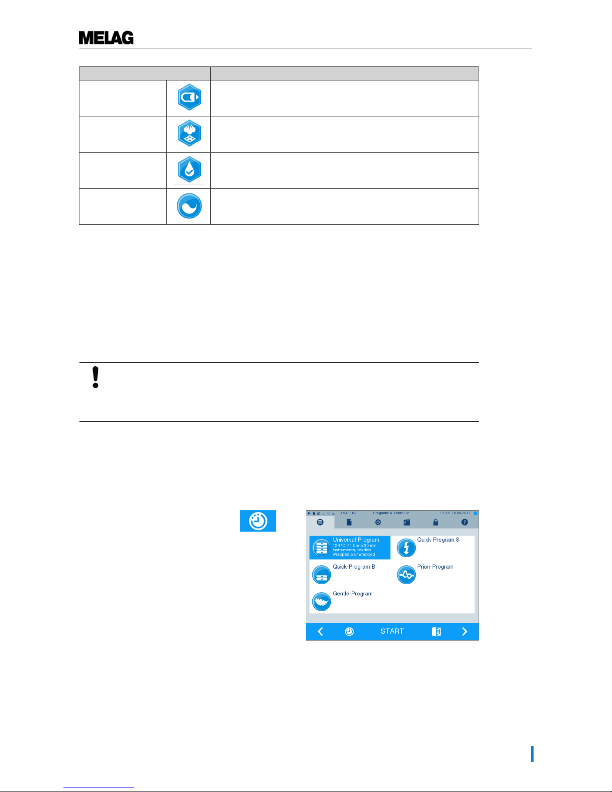
Additional programs Use/function
Vacuum test For measuring the leakage rate, test with a dry and cold device (test
without load)
Bowie & Dick test Steam penetration test with special test package (available from
specialist stockists)
Conductivity meas. For manual measurement of the feed water quality
Draining For emptying and pressure release of the double-jacket steam
generator, e.g. for service, maintenance or before transport
Additional program options
Additional drying
Used with the types of load specified in this chapter, the program-specific drying times guarantee very
good drying of the sterilized equipment. For difficult drying tasks you can activate the additional drying
function retrospectively during a running program, see Settings [}page 43].
Start time pre-selection
NOTICE
Unsupervised operation of electrical devices, including this steam sterilizer at the
operator’s risk. MELAG accepts no liability what so ever for any damage resulting from
unsupervised operation.
This function enables you to select any program and start it at a time of your choice. The start time preselection is only active for the unique time and program selection. That means that after completion of the
program, the pre-selected start time expires. You can switch-off the steam sterilizer during the start time
pre-selection. However, the steam sterilizer must be switched on before the timer runs out.
Please note, the security query means that this function is not possible for Quick-Program S. To set a
program start to a particular number, proceed as follows:
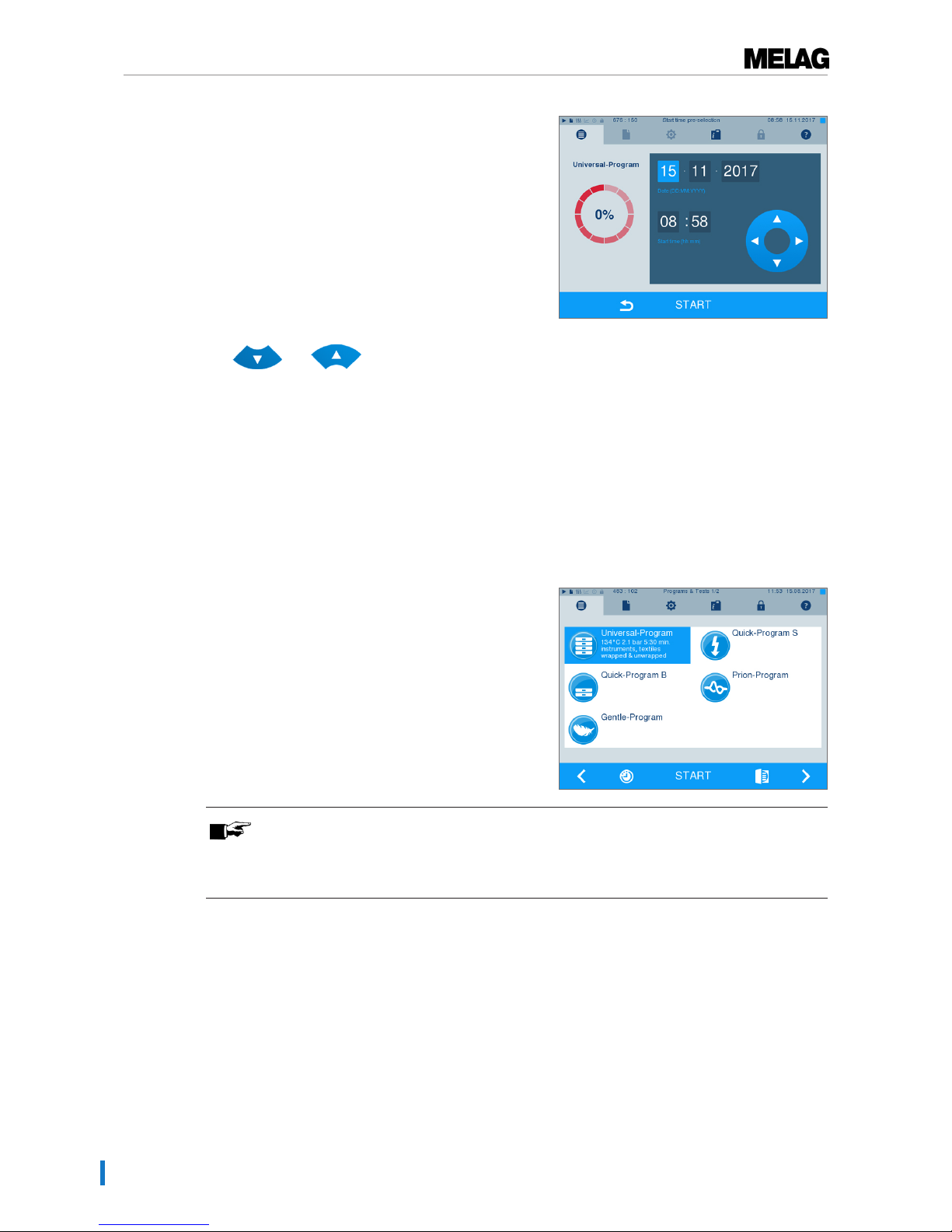
1. After selecting the program, press the
symbol in the action bar. The display switches to the
settings window.
Page 28
7 Sterilization
28
2. For example, to change the time, tap directly on the
parametersHour orMinutes. The selected field is
highlighted light blue.
3. Change e.g. the hour by pressing the pushbuttons
and .
4. Then press START. The display remains in the
start time pre-selection window.
Ê After the start of the start time pre-selection no
other menu apart from theInfo & Status
menu can be selected.
Starting the program
With the start of the program, the door closes pressure-tight and the steam sterilizer checks the quantity of
feed water and its conductivity.
}
To start a program, press the START key.
PLEASE NOTE
When starting Quick-Program S, a warning and an acoustic signal indicates that this
program only permits the sterilization of unwrapped instruments. If the load contains
wrapped instruments only, confirm with YES to start the program.
Program run
A program runs in three phases, the heating up and air removal phase, the sterilization phase and the
drying phase. After program start, you can follow the program run on the display. It shows the chamber
temperature and pressure as well as the time until the end of sterilization / the drying.
Sterilization phase
The display enables you to see whether the sterilization phase has already been completed successfully.
The coloured ring and the LED status bar switches from blue to green as soon as the drying phase has
been introduced.
Page 29
7 Sterilization
29
The sterilization phase is unsuccessful if the operator or the system (responding to a fault) aborts the
program run. A system abort returns the steam sterilizer to a pressureless state. This explains why a
system abort takes longer as an abort by the operator.
Drying phase
The steam sterilizer provides excellent drying of the sterilization material. If difficult-to-dry items require
better drying, you can undertake the following steps to improve drying:
u Load the steam sterilizer properly. Stand the transparent and paper sterilization packaging upright.
Comply with the specifications of section Loading the steam sterilizer [}page 23]. Use the optional
package holder if necessary.
u Activate theAdditional drying function.
Following the program run on the computer
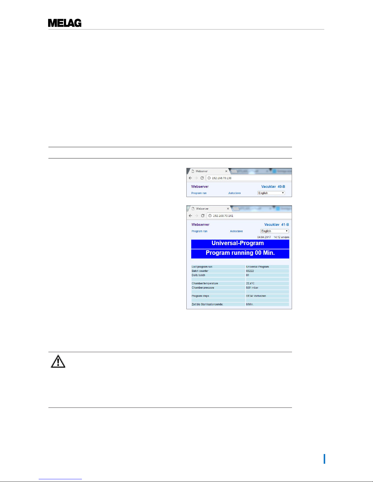
You can follow the current progress of a sterilization program on every computer in the practice network.
ü
The steam sterilizer has been assigned an IP address and is integrated in the practice network.
1. Open a web browser (we recommend Mozilla Firefox
or Internet Explorer) and enter the IP address of the
steam sterilizer in the address bar of the web browser.
2. Confirm with [ENTER]. Now you can display the
program run or information about your steam sterilizer
(e.g. serial number, software version and selected
values).
Manual program abort
You can abort a current program in all phases. If you end the program before drying begins, the
sterilization material remains unsterile.
WARNING
Hot steam can be released from the device when opening the door after a program abort.
This could result in burns.
n Use a tray lifter to remove the tray.
n Never touch the sterilized equipment, the chamber or the door with bare hands. The
components are hot.
Page 30
7 Sterilization
30
Program abort before the start of drying
WARNING
Danger of infection from early program abort
Aborting a program before the drying phase begins means that the load is unsterile. This
endangers the health of your patients and practice team.
n If necessary, repack the load and repeat the sterilization for the sterilization material
affected.
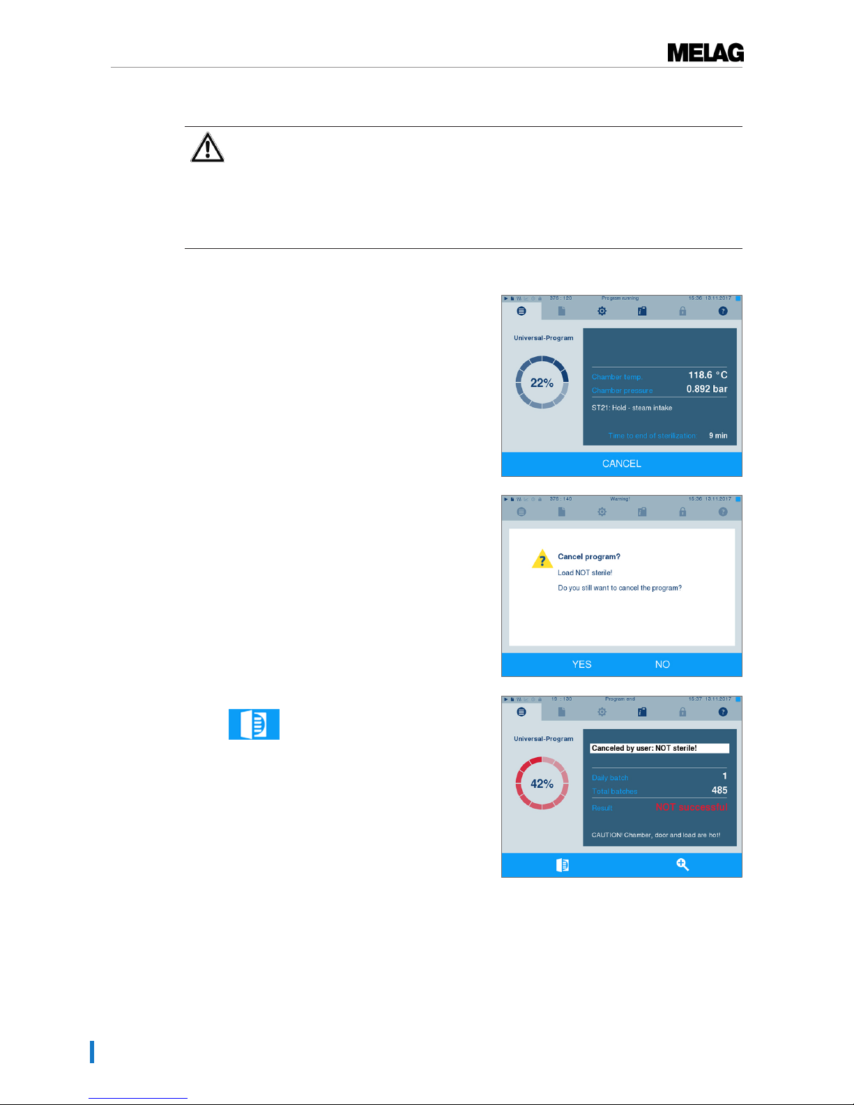
Should you still wish to do so, proceed as follows to abort the program during drying:
1. Press CANCEL on the action bar.
2. Confirm the security query with YES.
3. After a short time, you can open the door by pressing
the symbol. The display shows a warning;
the log records the sterilization asNOT
successful.
Program abort after the start of drying
Should you abort a program after drying has started, the sterilization is having been completed
successfully. The steam sterilizer issues a malfunction message. You then need to expect insufficient
drying, especially in the case of wrapped sterilized equipment and a full load. Sterile storage requires
sufficient drying. To ensure this, please allow programs with wrapped sterilized equipment to continue to
the end of the drying phase as far as is possible. Unwrapped instruments sterilized in a Quick-Program dry
after being removed from their own warmth.
Page 31
7 Sterilization
31
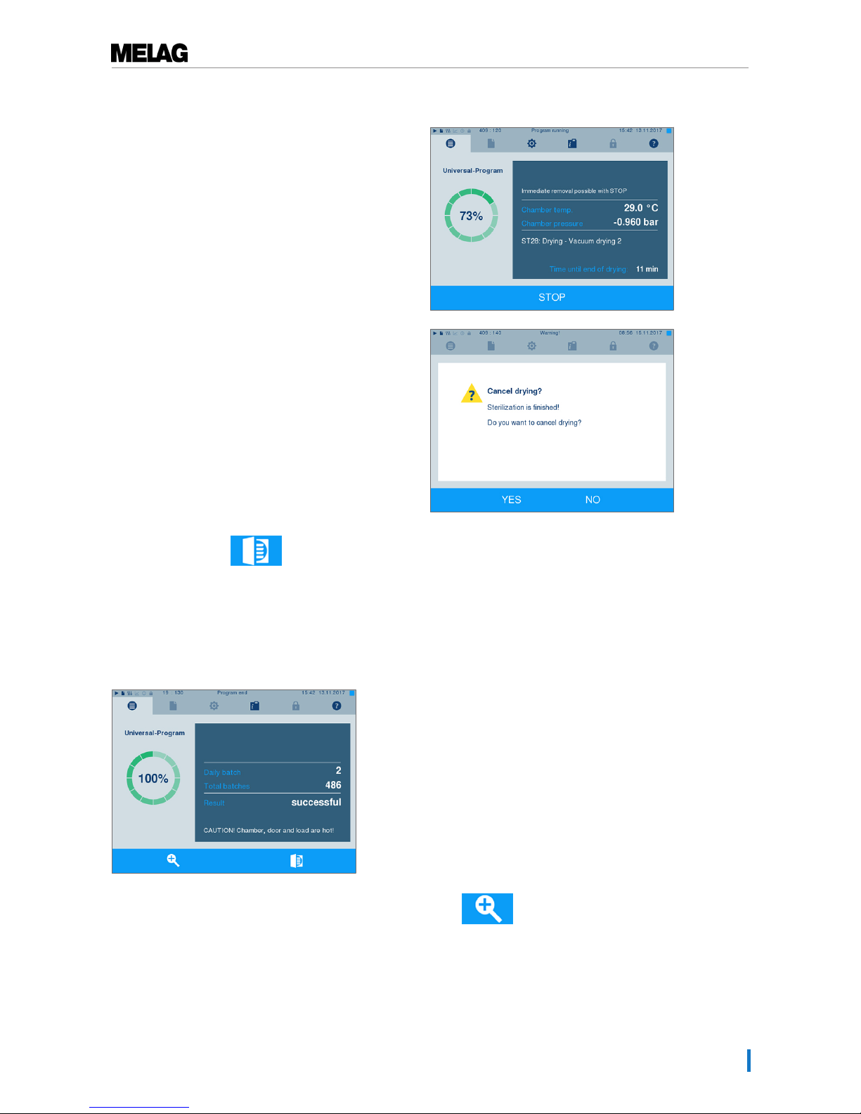
Proceed as follows to abort the program during drying:
1. Press STOP on the action bar.
2. Confirm the security query with YES.
3. After a short time, you can open the door by
pressing the door symbol.
Program end
When the program has ended successfully, the corresponding message will be issued on the display.
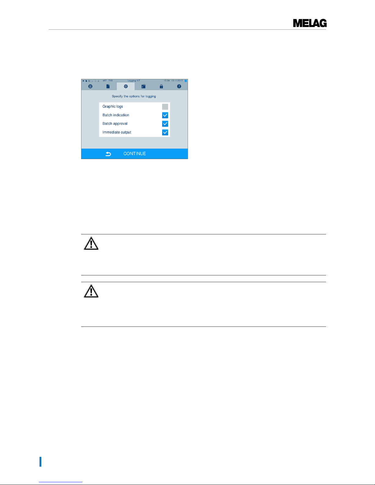
Working in theSettings menu →Logging if immediate output after program end is activated, (=
Immediate output), the log of the completed program will be outputted to the activated output medium after
opening the door.
Before opening the door, you can view further values from the program which has just completed, e.g. the
plateau time conductivity by pressing the magnifying glass symbol .
Page 32
7 Sterilization
32
The approval process
According to RKI "Hygiene requirements for the treatment of medical products", instrument treatment ends
with the documented approval for storage and application of the sterilized equipment. The approval
process consists of batch indication and batch approval and must be performed by authorized and expert
personnel.
Batch indication comprises the checking of the indicators used in the sterilization program e.g.
MELAcontrol/MELAcontrol PRO. Approval of the indicator strip is possible only if it changes colour entirely.
Batch approval comprises the checking of the process parameters using the sterilization results on the
steam sterilizer and the sterilization log as well as checking of the individual packaging for damage and
residual moisture. The sterilization log records the approval of the batch and any indicators. Depending on
the setting in the user administration, approval for the sterilized equipment requires the user PIN of the
person who provides approval for the batch and the indicators.
Removing the sterilized equipment
CAUTION
Danger of burns from hot metal surfaces
n Allow the device to cool sufficiently before opening.
n Do not touch any hot metal parts.
CAUTION
Unsterile instruments resulting from damaged or burst packaging. This endangers the
health of your patients and practice team.
n Should the packaging be damaged or have burst, re-pack the sterilization material and re-
sterilize it.
If you remove the sterilized equipment from the device directly after the end of the program, it is possible
that the instruments can be partially damp. According to the Arbeitskreis für Instrumentenaufbereitung
(AKI; red broschure 10. Edition; S.57): "In practice, residual moisture in the form of a few drops of water
capable of evaporating within 15 minutes is tolerated, but actual pools of water are not acceptable."
Comply with the following specifications when removing the sterilized equipment:
u Never use force to open the door. This could damage the device and / or result in the emission of hot
steam.
u Hold the mount level when removing it from the steam sterilizer. Otherwise, the load could slide off.
u When removing the load from the steam sterilizer separately, ensure that the mount does not slide out
unintended.
u Use a tray lifter to remove the tray.
u Never touch the sterilized equipment, the device interior or the inside of the the door with unprotected
hands. The components are hot.
u Check the packaging on the sterilized equipment for damage when removing it from the device.
Should the packaging be damaged, re-pack the sterilization material and re-sterilize it.
Page 33

7 Sterilization
33
Storing sterile instruments
The maximum storage time is dependent on the packaging and the storage conditions. For standardconform packaged sterilized equipment – (if protected from dust) it can amount to up to six months.
Comply with the provisions of DIN 58953, part 8 and the criteria specified below for the storage of
sterilized equipment:
u Comply with the maximum storage duration in accordance with the packaging type.
u Do not store the sterilized equipment in the decontamination room.
u Store the sterilized equipment in a dust-protected environment e.g. in a closed instrument cabinet.
u Store the sterilized equipment in a moisture-protected environment (e.g. alcohol, disinfectant)
u Store the sterilized equipment in an environment protected against excess temperature variations.
Page 34

8 Logging
34
8 Logging
Batch documentation
The batch documentation acts as proof of the successful conclusion of the sterilization process and
represents an obligatory part of quality control. The data, such as type of program as well as batch and
process parameters of the completed programs, are stored in an internal log memory of the device.
To obtain the batch documentation, you can read out the internal log memory and transfer its data to
various output media. This can be performed immediately at the end of every program or at a later point,
such as at the end of the day.
Capacity of the internal log memory
The steam sterilizer is equipped with an internal log memory. This saves all the data regarding the
sterilization program automatically. The capacity of the internal log memory is sufficient for c. 100 logs. If
the internal log memory becomes almost full and at least one log has not been outputted via an activated
output medium, the following warning "Internal log memory is almost full" will appear on the display. If this
warning appears, working in theSettings menu →Logging provide the pre-determined output media
and output the logs affected (→Log output menu).
Shortly afterwards, the following message is displayed:Internal log memory full. You now have the last
chance to archive logs which have not been outputted (confirm query with YES) before the data in the
steam sterilizer log memory (up to the last 40 logs) is automatically deleted.
Output media
You are able to output and archive the logs of the completed programs on the following output media:
▪ MELAflash CF card
▪ Label print-out with the MELAprint 60 label printer
▪ MELAprint 42/44 log printer with network adapter
▪ A computer (via the practice network)
Any combination of the output media is possible. Log output on multiply activated media is performed
successively. In its delivery state, the MELAflash CF card is activated as the output medium for text and
graphic logs from the steam sterilizer. Automatic logging (= Immediate output) is thus activated.
Detailed information regarding the activation and setting of log output is to be found in the chapter settings,
logging [}page 43].
Using the CF card as an output medium
NOTICE
Premature removal of the CF card from the card slot or its inappropriate handling can
result in data loss, damage to the CF card, the device and/or its software.
n Never push the CF card in the slot with force.
n Never remove the CF card from the slot whilst it is being written or read. The square in the
upper right-hand corner of the display lights up during reading and writing access.
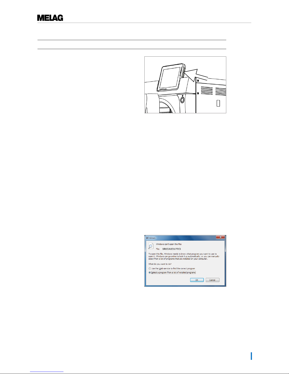
The card slot for the CF card is located on the right-hand side of the display housing.
Page 35
8 Logging
35
Proceed as follows in order to insert the CF card in the slot.
ü
The CF card is set as the output medium in theSettings →Logging menu.
1. Insert the CF card in the card slot fully with the raised
finger edge pointing rightwards and to the rear.
If the CF card is inserted correctly, a blue square will
illuminate in the right upper corner of the display.
2. Check whether the CF card has been selected as
the output medium.
Using the computer as an output medium
You can connect the steam sterilizer directly to a computer or integrate it in an existing (practice) network
via FTP or TCP. The computer must be fitted with a RJ45 socket (LAN).
Further information pertaining to the requirements and setting of the computer as an output medium is
available in the chapter Settings, logging [}page 43].
Reading out a text log on the computer
All text logs can be opened and printed out using a text editor, a word processing program or a
spreadsheet program. Graphic logs can only be displayed with the MELAtrace/MELAview documentation
software.
Each text log (e.g. PRO, .STR, .STB etc.) must be linked with the text editor to enable the computer to
open them automatically with a text editor. The meanings of the endings are outlined in the section
Subsequent log output [}page 37]. The following examples show how you can link the Windows7 editor
with a specific text log.
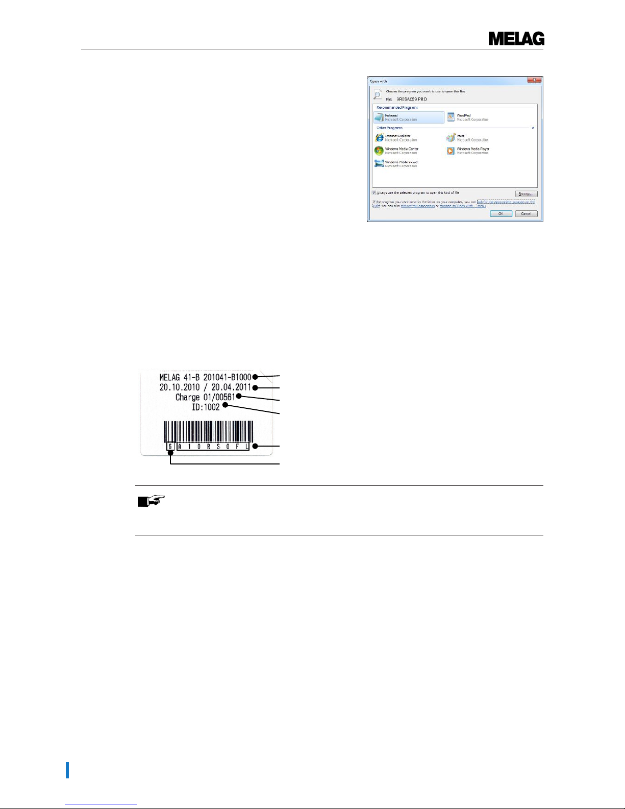
1. Working in Windows Explorer, double click on the
log file.
2. If the file ending is unfamiliar, Windows7 will display
the following message:
Page 36
8 Logging
36
3. Select "Select a program from a list of installed
programs" and confirm with "OK".
4. You can then open files with this ending via a
double-click in Windows Editor.
Using the label printer as an output medium
The use of a label printer facilitates batch traceability. Using the sterilization date, the storage duration,
batch number, user ID of the person approving the application for use, the steam sterilizer used and the
file name it is possible to assign the sterilized instruments to the patient and sterilization batch. Faultless
packages containing sterilized equipment are marked with labels after sterilization. As such, the
preconditions for correct "Approval" by the person conferred with the task of decontamination are given. All
information regarding the correct sterilization procedure can be attributed to the instruments used in
patient records.
Type, serial number
Sterilization date/total batches
Daily batches/No. total batches
User ID
File name
Storage period
PLEASE NOTE
To facilitate easy assignation of a package marked with a label to a specific batch, the
sterilization log file name must not be changed.
Outputting text logs automatically after program end
(immediate output)
If you want to output the associated text and graphic logs on an output medium immediately after the end
of a program, use the "Immediate output" option. In its delivery state, the immediate output of the text and
graphic logs via the CF card after program end is activated.
If the output medium selected for this purpose has not been connected, the logs are saved in the internal
memory and a warning is issued. The steam sterilizer provides the option of outputting this log at the next
possible opportunity. Graphic logs cannot be saved in the internal log memory; they are lost. Further
information pertaining to the output of graphic logs is available in the section Outputting graphic logs
(optional) [}page 43].
The following points must be fulfilled for immediate output:
u The date and time have been set correctly.
u The output medium must have been selected and connected.
u Immediate output must be activated in theSettings menu →Logging.
Page 37
8 Logging
37
Information regarding the setting of immediate output and the desired output medium is provided in the
chapter Settings, logging [}page 43].
Subsequent log output
TheLog output menu provides the option of outputting text logs subsequently and independently of the
point of the program end. You can set the output media yourself. The output medium is selected as
standard, which are also selected underSettings →Logging, as far as automatic immediate output is
activated.
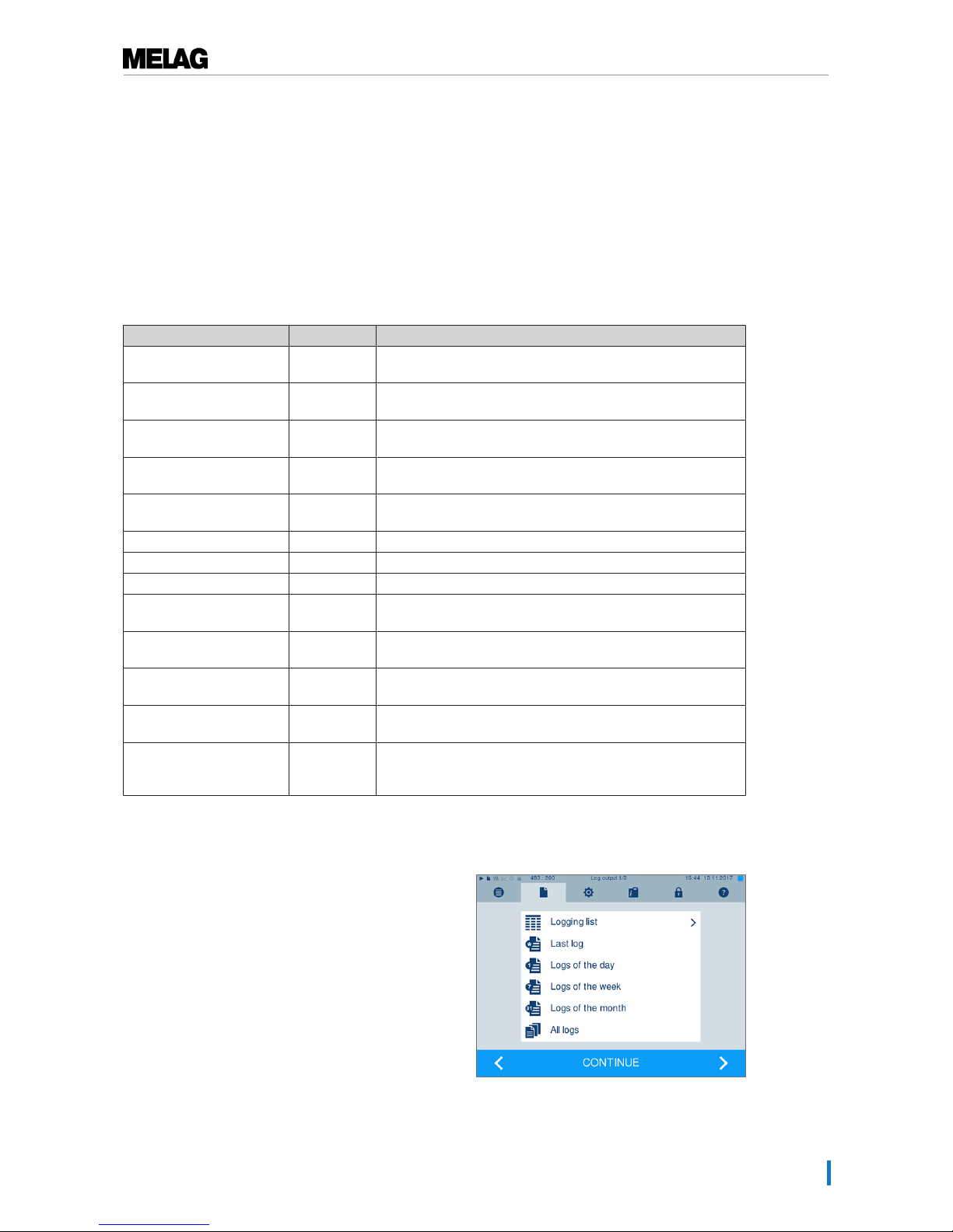
The Log output menu offers various opportunities for log output. All program logs present in the memory
are displayed in the Logging list. You can sort the list according to date, time, program and outcome by
pressing on the column headings. Here is an overview of all possible output media.
Designation File ending Explanation
Last log .PRO The log of the last successful completed program is
outputted.
Logs of the day .PRO The log of the last successful program of the current day is
outputted.
Logs of the week .PRO Logs of all successfully completed programs of the week -
Monday to Sunday - are outputted.
Logs of the month .PRO Logs of all successfully completed program performed in the
current month are outputted.
All logs .PRO The logs of all the successfully completed programs are
outputted.
Last fault log STR The last malfunction log are outputted.
Fault logs of the day .STR The malfunction logs of the current day are outputted.
etc. ...
Legend log file .LEG Contains an explanation of all abbreviations contained in the
log.
Status log .STA A summary of all important settings and system states
(counter, measured values etc.)
Fault in standby .STR This log type is generated following the malfunctions
registered during a time at which no program was active.
System log .LOG A sort of log book listing all malfunctions and changes to the
system in order of their incidence.
Delete all logs Deletes all logs stored in the internal log memory. Caution: All
logs will be deleted which were not previously outputted to
another output medium.
Outputting a log from the log list
Proceed as follows to output a specific log from the internal memory:
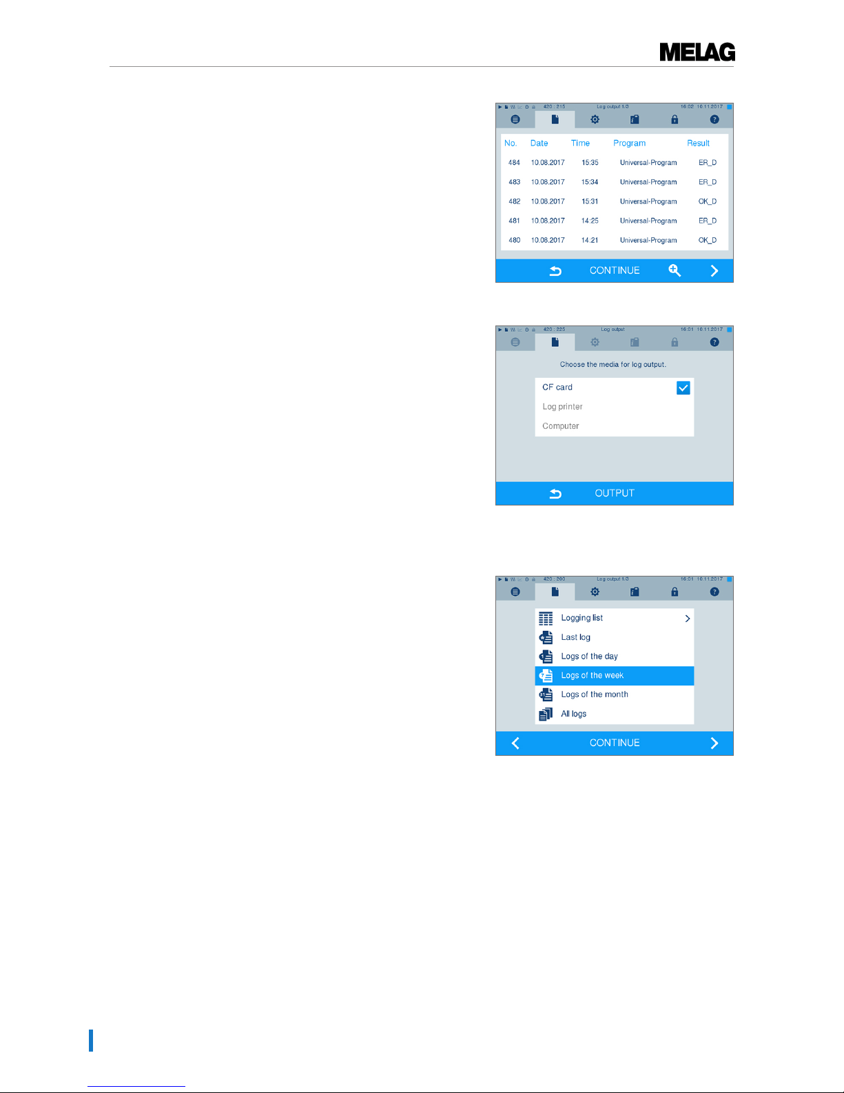
1. Navigate to theLog output menu and
selectLogging list.
Page 38
8 Logging
38
2. A list with all text logs is displayed which have been
saved in the internal memory. To ease the search,
you can filter the log sort sequence by date, program
or event by selecting the top line.
3. Select a log and press CONTINUE.
4. Select an output medium and press OUTPUT.
Outputting the daily/weekly logs etc.
Proceed as follows e.g. to output all the logs of a week:
1. Navigate toLog output and selectLogs of the
week.
2. Press CONTINUE.
3. Select an output medium and press OUTPUT.
Proceed in a similar fashion to output all logs, all the logs of that month etc.
Page 39
8 Logging
39
Finding a log
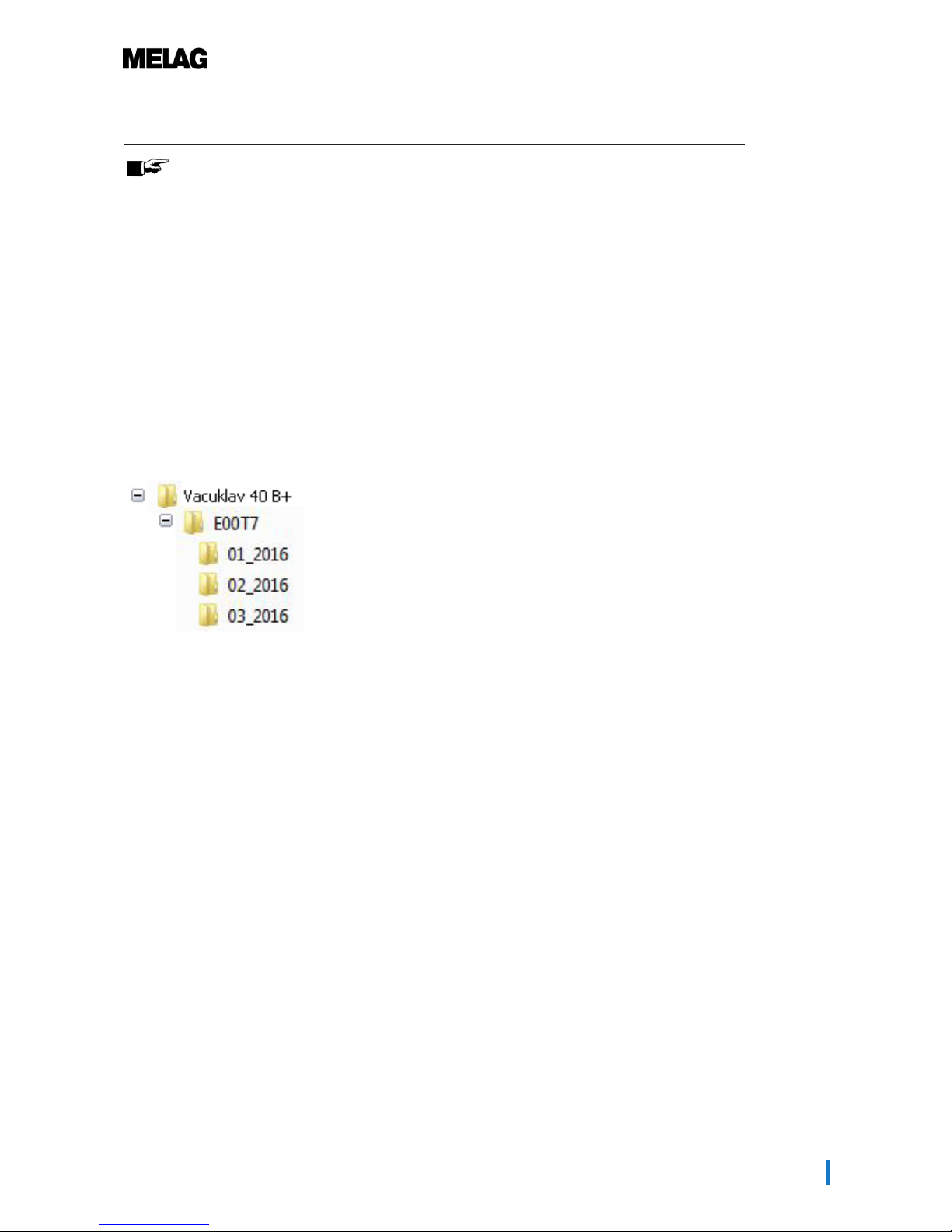
PLEASE NOTE
If possible, do not rename the directories, otherwise logs will be stored in both the
renamed directory as well as the new device directory generated automatically by the
steam sterilizer.
Storage location for logs
When transferring the logs to a CF card, they will be stored in a separate folder in the main directory.
Direct transfer of the log to a computer via the network and using the MELAG FTP server allows you to
work directly in the FTP server to determine directly where on your computer the device directory with log
files is to be saved. With output via TCP and e.g. MELAtrace, you can work directly in the program to
determine the folder in which they are to be saved.
Log directory
All memory media (CF card or computer) contain a folder with the encoded serial number of the steam
sterilizer concerned. The folder name consists of five characters identical with the first five characters of
every log, e.g. E00T7. This folder contains sub-folders with the month of log generation e.g. 01_2016 for
January 2016. This contains all logs generated by the steam sterilizer this month. The device directory is
entered in the main directory on the CF card.
The steam sterilizer checks the memory medium after every type of log output (immediate output after a
completed cycle or the transfer of multiple logs simultaneously). Should a directory not exist, it
automatically creates a directory for the device and the month. If the logs are subject to multiple outputting
on the identical memory medium, the device directory will create a "Duplicate" directory.
Further information pertaining to the meaning of the file endings on the logs is available in section
Subsequent log output [}page 37].
Page 40

8 Logging
40
---------------------------------------!0 01100ED0E001
!1 E00T717U.PRO
---------------------------------------10 MELAG Vacuklav 41 B+
---------------------------------------15 Program: Universal-Program
20 Program type: 134 °C wrapped
25 Date: 09.03.2017
30 Daily batches: 14 Total: 01578
35 User: Deactivated
36 Indicators changed: deactivated
37 Batch approved: deactivated
======
40 Universal-Program successfully
completed
42 = =
======
45 Temperature: 135.3 +0.25/-0.18 °C
50 Pressure: 2.17 +0.02/-0.01 bar
55 Plateau time: 05 min 30 s
60 Conductivity: 8 µS/cm (359:11.1)
65 Start time: 20:22:01
70 End time: 20:43:19 (21:18 min)
======
80 SN:201441-B1051
======
81 MR V3.218 09.03.2017
82 Para V3.226 17.02.2017
83 BO V3.323 09.03.2017
---------------------------------------Step Time t[m:s] P[mbar] T[°C]
SP-S 0:00 0:00 1002 96.3
SK11 0:13 0:13 1680 95.7
SK12 0:37 0:24 1285 104.8
SK11 0:46 0:09 1665 106.8
.
.
SK22 2:38 0:20 1284 116.6
SF12 3:12 0:34 499 112.7
SF13 3:42 0:30 1667 113.3
.
SF43 8:25 0:24 1749 113.6
SH01 9:10 0:45 2780 130.5
SH02 9:31 0:21 2847 131.7
SS01 9:53 0:22 3065 134.0
SS02 15:23 5:30 3169 135.3
SA00 15:53 0:30 1292 112.1
SI02 17:33 1:40 79 57.9
.
SB10 21:14 0:12 804 91.3
SB20 21:18 0:04 919 92.3
SP-E 21:18 0:00 925 92.3
>> Never change the code in the following
line <<
010041D8BE14B1319E55772A0DF975054F7EBF32
EE1372767ED3B3801EB10F3FB01A3212D41D7144
1C3B8B6474777962766F018680B68C56C219074F
D6E7814D506F0A2F3077782541CC2CD05C425DA1
9A5EF5192C68174C868556542F7B8B05E97C6E46
16CDCFFA811E126FD67363FB74128A5F83AE6F37
F45A9E240C88615F1618D340060C1027205C83C2
>>Authentication of batch log<<
----------------------------------------
0.00 0.0 0.0 0.0 ---.- 0.0
-edk----etm---etd---etp---etv--ett-END-
!0 Ident number
!1 File name
---------10 Steam sterilizer type
---------15 Program name
20 Program sterilization parameters
25 Date
30 Daily and total batch number
35 User ID
36 Batch indication
37 Batch approval
=====
40 Control notification
42 Warning or malfunction message with program abort
=====
45 Sterilization temperature with max. deviations
50 Sterilization pressure with max. deviations
55 Sterilization time
60 Conductivity of the feed water
65 Time at program start
70 Time at program end
==========
80 Device serial number
==========
81 Current version of the device firmware
82 Current version of the device parameters
83 Current version of the user interface
---------Step – Program step
Time – Time (min:sec) which has elapsed since the program
start
t [m:s] – Duration (minutes:seconds) which a program step
requires
P [mbar] – Chamber pressure
T [˚C] – Chamber temperature
Key for the program steps:
SK – Conditioning
SF – Fractionation
SH – Holding
SS – Sterilization
SA – Pressure release
ST – Drying
SI – Intelligent drying
SB – Ventilation
SP-E – End
Proof of authenticity (electronic signature)Should never
be altered; decoding the code (by MELAG) indicates
whether the data was generated on a MELAG steam
sterilizer and has been changed.
---------Sensor measurement values are displayed here in the
case of a malfunction. The values are helpful for a
technician.
Fig.4 : Example log of a successfully completed program
Page 41
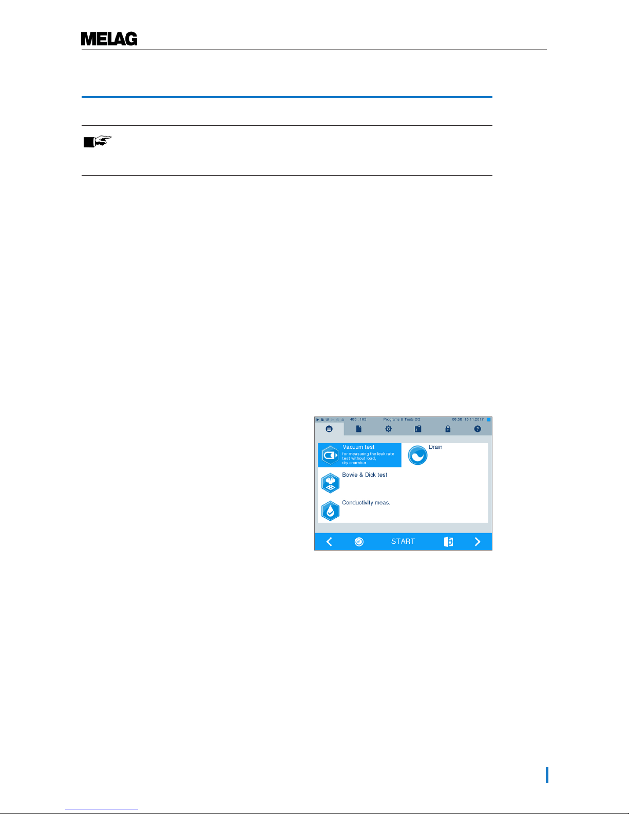
9 Functional checks
41
9 Functional checks
PLEASE NOTE
Please comply with the recommendations issued by the Robert-Koch-Institute (RKI) and
DIN 58946-7.
Manual functional checks
You can follow the program run on the display via the values displayed there. You can also use the logs
recorded for every program to determine the success of a program. The test programs enable you to
perform an additional function check at any time.
Vacuum test
The steam sterilizer can be checked for leakages in the steam system using the Vacuum test. This
determines the leakage rate at the same time.
Perform a vacuum test in the following circumstances:
▪ Once a week in routine operation
▪ During commissioning
▪ Following longer operating pauses
▪ Following a malfunction (e.g. in the vacuum system)
Perform the Vacuum test with the steam sterilizer in a cold and dry state as follows:
1. Switch on the steam sterilizer at the power switch.
2. Working in thePrograms & Tests menu, select
vacuum test and press START.
Ê The evacuation pressure and the equilibration
time or measuring times are shown on the
display. The chamber will be ventilated after the
end of the measuring time. Then the message
will be shown on the display with an indication
of the leakage rate. Should the leakage rate be
too high e.g. over 1.3 mbar, a corresponding
message will be issued on the display.
Page 42
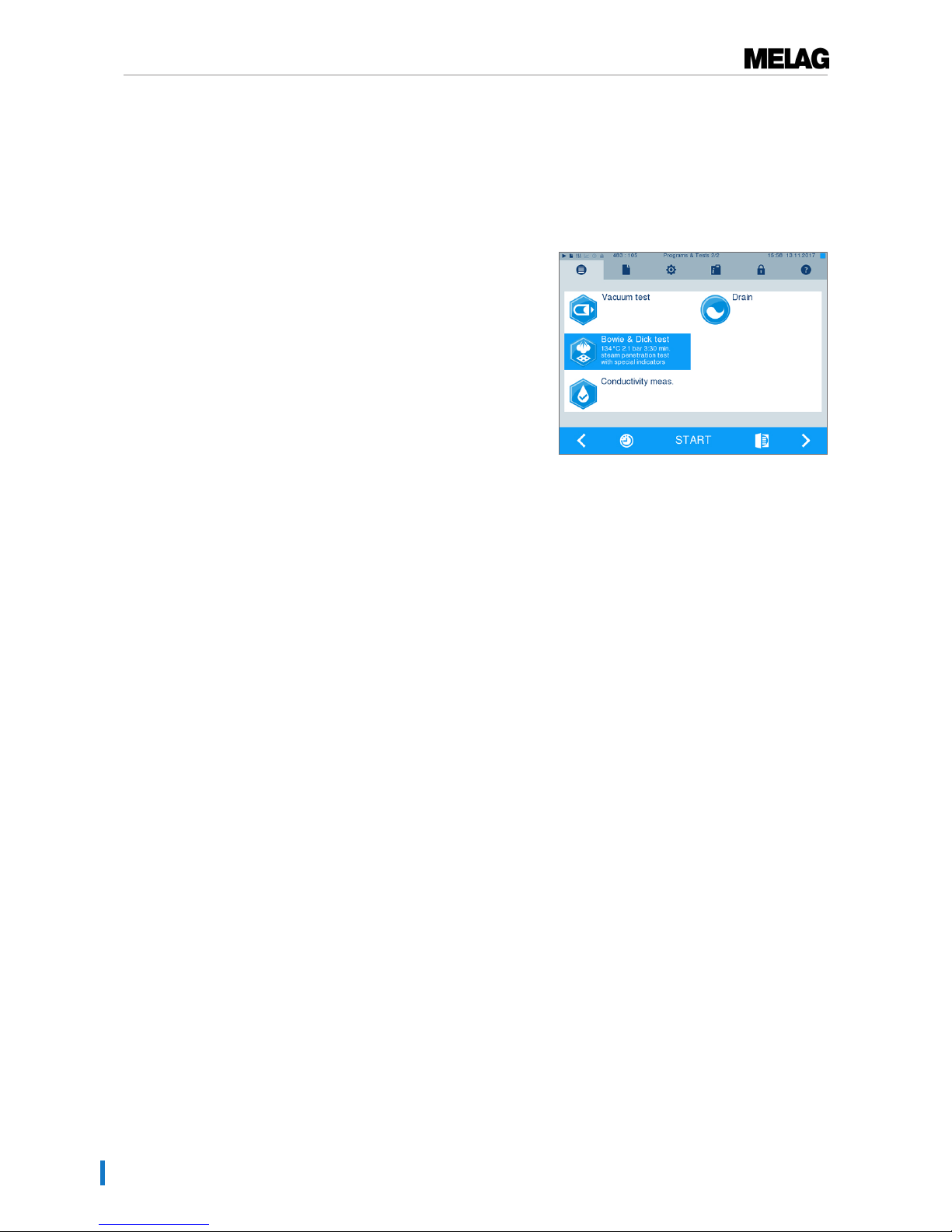
9 Functional checks
42
Bowie & Dick test
The Bowie & Dick test serves as the proof of steam penetration of porous materials such as e.g. textiles.
You can perform a routine function check for proof of steam penetration. Use the Bowie & Dick test
program to this end. Specialist stockists provide various test systems for the Bowie & Dick test. Perform
the test according to the test system manufacturer information.
1. Switch on the steam sterilizer at the power switch.
2. Working in thePrograms & Tests menu, select
Bowie & Dick test and press START.
Evaluation of the indicator documents following the colour change
Depending on the manufacturer batch, treatment indicator strips often exhibit differing intensities in the
colour change resulting from different lengths of storage or other influences. Of crucial importance for
evaluating the Bowie & Dick test is not the strength of contrast in the colour change on the test sheet, but
its even nature. If the treatment strips / treatment indicator sheet indicates an equal distribution of colour
change, the air removal of the sterilization chamber is without fault. If the treatment indicator strips or the
treatment indicator sheets are uncoloured or exhibit less colour in the centre of the star in comparison to
the end, air removal was insufficient. In such a case, please consult the stockist customer services of the
customer services / authorized stockist.
Page 43
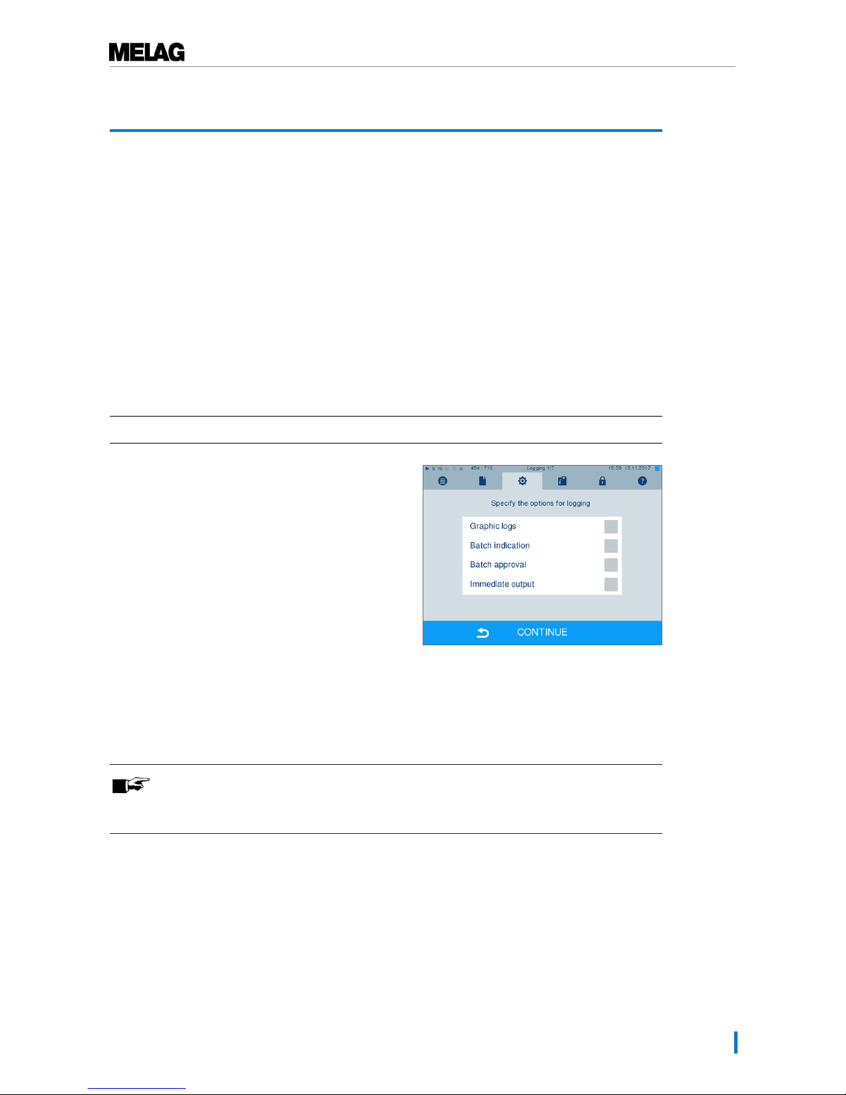
10 Settings
43
10 Settings
Logging
All settings pertaining to the output of text and graphic logs i.e. output medium, log format, immediate
output etc. are performed in the Settings menu →Logging.
To this end, you are led through a settings wizard.
Immediate log output
In its delivery state, the immediate output of the text and graphic logs via the CF card is activated
immediately after the program end.
Deactivate immediate output
If log output is not to be performed immediately following the end of a program, but saved in the internal
memory, (e.g. to be collected and outputted together within a single week), you can deactivate the
immediate output option. Proceed in the following fashion:
ü
Navigate toSettings →Logging.
1. Remove the checkmark in front of theImmediate
output option.
2. Press repeatedly on CONTINUE until you come to
the summary window.
3. Press SAVE to save the setting.
Outputting graphic logs (optional)
PLEASE NOTE
Graphic logs cannot be saved in the internal log memory. A subsequent output of
graphic logs is thus not possible.
Page 44
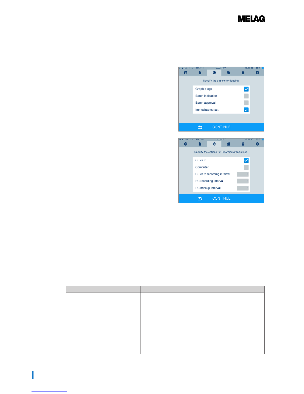
10 Settings
44
If you wish to output a graphic log (optional) in addition to a text log, proceed as follows:
ü
Navigate toSettings →Logging.
ü
Immediate output is activated.
1. Set a checkmark next to the Graphic logs option and
check whether the checkmark is also set next to the
Immediate output option.
2. Press CONTINUE and select the CF card and/or
computer as an output medium.
3. If necessary, change the intervals and press
CONTINUE.
4. Working in this window, check whether at least one
of the two output media have been selected for text
logs.
5. Check whether the activated output medium is
connected (computer) or has been inserted
(MELAflash CF card).
6. Press repeatedly on CONTINUE until you come to
the summary window.
7. Press SAVE to save the setting.
Explanation of the possible settings for graphic recording:
Interval Explanation
CF card (CFC) recording interval in sec. – indicates the time intervals in which the program curve
is recorded on the CF card. The smaller the time interval, the
more exact the curve. In the example, the time interval is set at 1
second.
PC recording interval in sec. – indicates the time intervals in which the program curve
is recorded, if the computer is selected as output medium. The
smaller the time interval, the more exact the curve. In the
example, the time interval is set at 1 second.
PC backup interval in sec. – indicates the time interval in which the graphic data from
the steam sterilizer is saved on the computer. In example 1, the
backup interval is set to 1 seconds.
Page 45
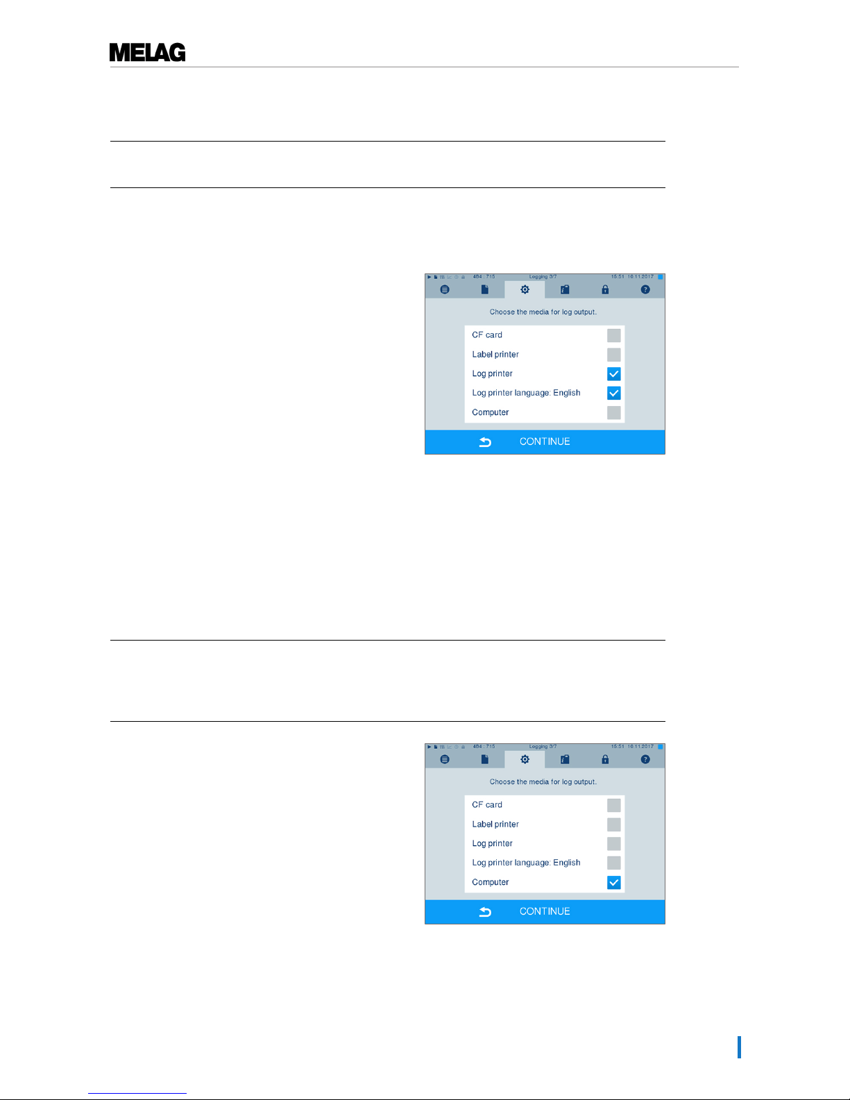
10 Settings
45
Log output in English
If you want to print all text logs on the MELAprint log printer in English, proceed as follows:
ü
The text log is to be printed in English, regardless of the language of the display.
ü
You are in the menuSettings →Logging.
1. Press repeatedly on CONTINUE until you reach the
log output menu.
2. Select theLog printer as an output medium.
3. In addition, selectLog printer language:
English.
4. Press repeatedly on CONTINUE until you come to
the summary window.
5. Press SAVE to save the setting.
Ê The output of the text logs on the MELAprint log
printer is in English.
Using the computer as an output medium
Log transmission can be performed via an FTP server / service or TCP. The following section shows how
to set the desired connection:
ü
Navigate to theSettings →Logging menu.
ü
The steam sterilizer is connected to a computer via a network cable (RJ45).
ü
Depending on the output type, an FTP server / service or a suitable program e.g. MELAtrace /
MELAview is installed.
1. Press on CONTINUE until you reach the window for
selecting the output medium.
2. Select the computer as an output medium and
press CONTINUE.
Ê The selection window opens and asks whether
the connection to the computer should be
effected via FTP or TCP.
Page 46
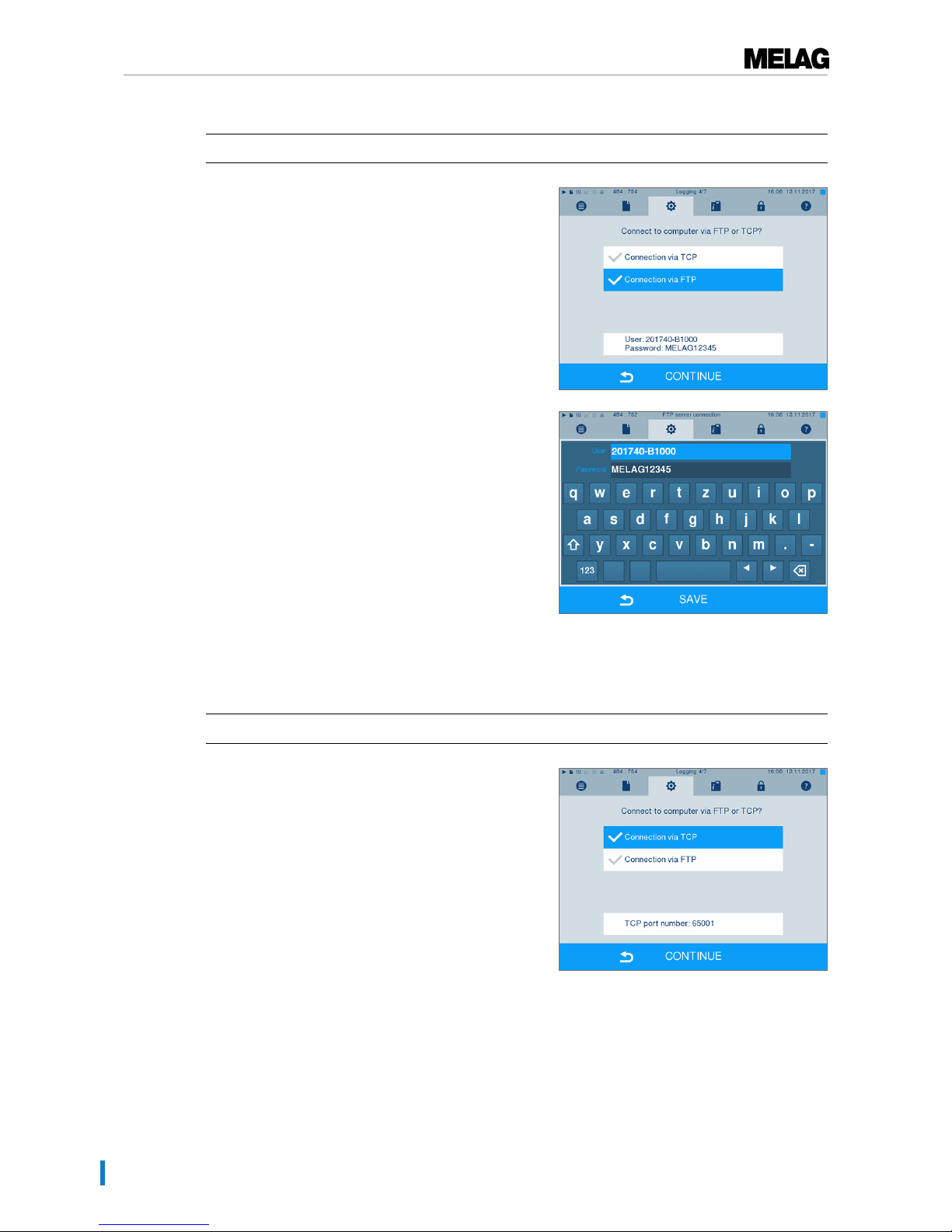
10 Settings
46
Connection via FTP
ü
An FTP server or an FTP service is installed on the computer.
1. SelectConnection via FTP. The lower
pushbutton displays the current user data settings
(standard user name: Year of construction +
manufacture number; Password MELAG12345).
2. Press this pushbutton to change the pre-set TCP user
data. The display switches to the settings window.
3. Enter the user name and password and confirm
with SAVE.
Connection via TCP
ü
A suitable documentation software e.g. MELAtrace is installed.
1. SelectConnection via TCP. The TCP port
currently set is displayed on the lower pushbutton
(Standard TCP port: 65001).
Page 47
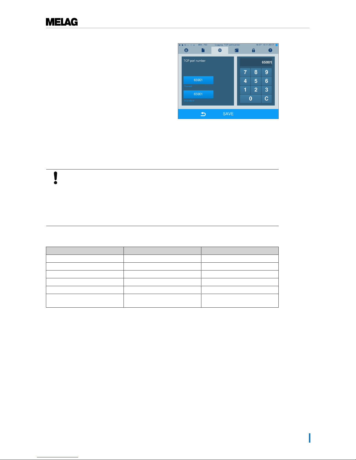
10 Settings
47
2. Press on this pushbutton to change the pre-set TCP
port. The display switches to the settings window.
3. Delete the most up-to-date TCP port using button
C; enter another TCP port.
4. Confirm with SAVE.
IP addresses
PLEASE NOTE
Those setting up the (practice) network will require in-depth understanding of the
network technology.
Errors in the handling of IP addresses can result in malfunctions and data loss in your
user network.
n Setting of IP addresses should only be performed by the system administrator of the
(practice) network.
The device is equipped as standard with IP addresses which all belong to a common network with the
subnet mask stated in the following depiction.
Device IP address Remarks
Steam sterilizer 192.168.40.40 Preset works side
Computer 192.168.40.140 Preset works side
Log printer MELAprint 42/44 192.168.40.240 Preset works side
Label printer MELAprint 60 192.168.40.160 Preset works side
Gateway 192.168.40.244 Not relevant within a network
Subnet mask 255.255.255.0 Possibly to be adopted by
customer network
Page 48
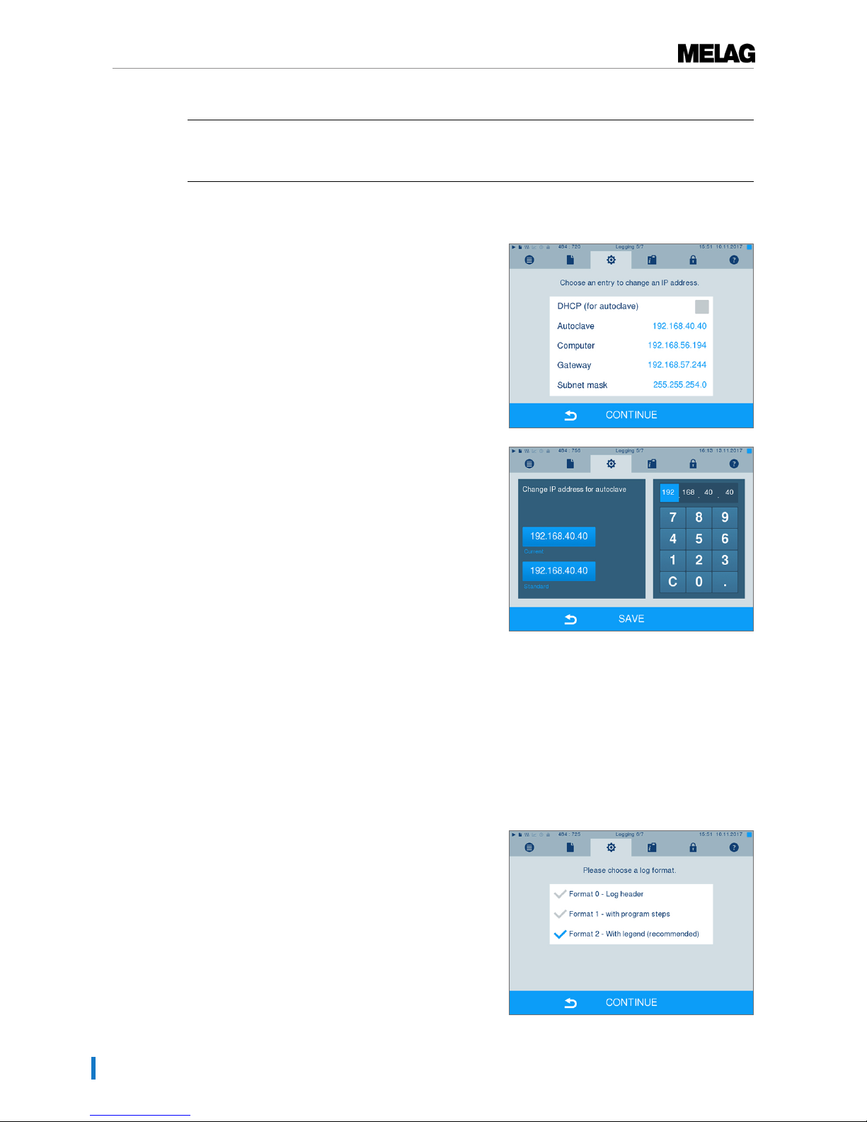
10 Settings
48
If a device is to be integrated in a pre-existing (practice) network, observe and comply with the following:
ü
The IP addresses listed in the table have not yet been assigned in the (practice) network.
ü
The device cannot be automatically administered in a dynamic (practice) network (i.e. a DHCP
network).
1. Select theSettings menu →Logging. The
setting wizard opens.
2. Working in the logging wizard, navigate to the window
in which the IP addresses of the individual devices are
listed.
3. Select e.g. the steam sterilizer. The settings window
opens.
4. Select the number block which you wish to change
directly.
5. Use the C button to delete the numbers. Enter a
new number block and confirm with SAVE.
6. Proceed in a similar fashion with the other devices
which are to be integrated in the network.
Log format
Different data is issued depending on the nature of the logging format.
}
The logging format is determined underSettings
→Logging.
You can choose between the following formats.
Page 49
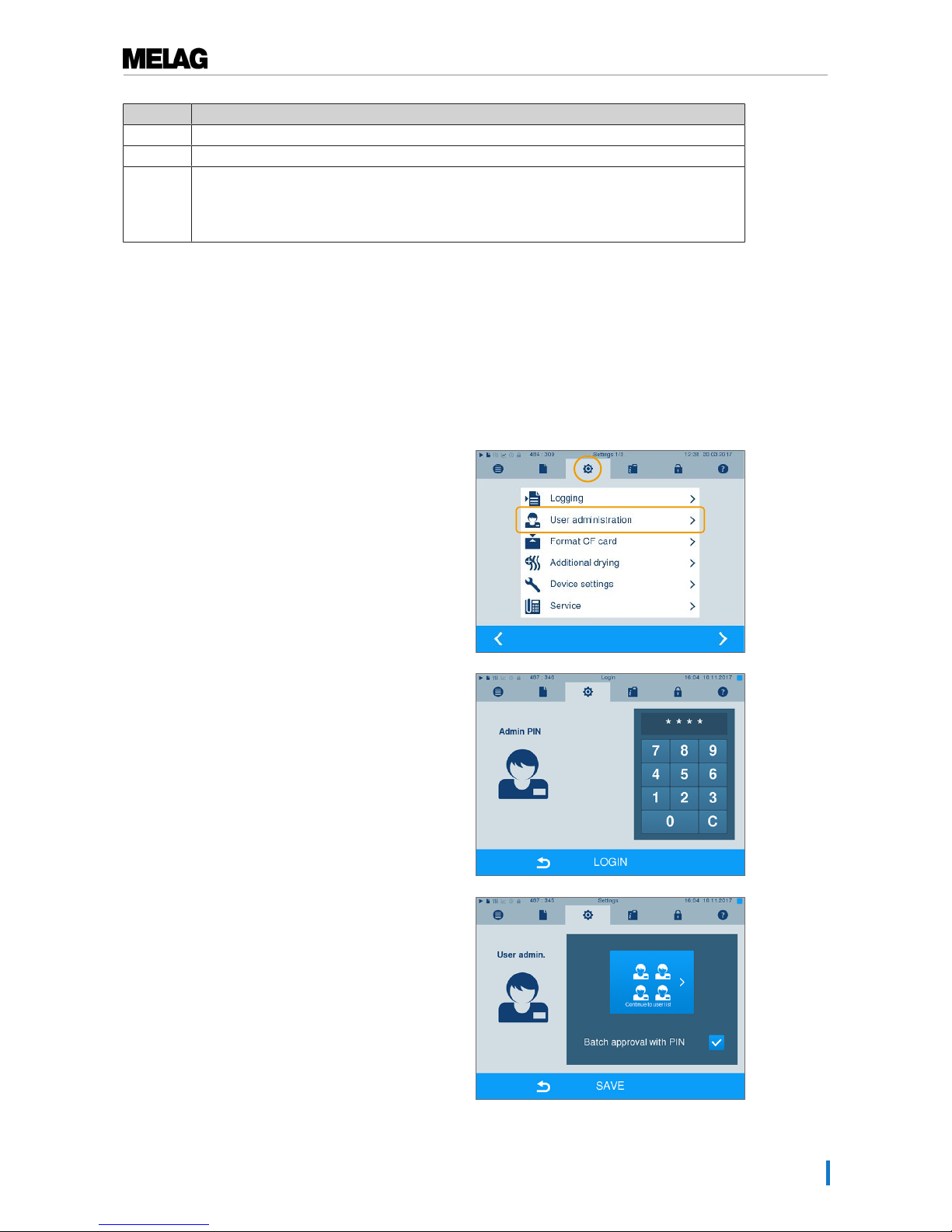
10 Settings
49
Format Description
Format 0 Short form - only the log header is outputted.
Format 1 The log header and the program steps are outputted.
Format 2 Standard format - in addition to the log header and the program steps, a key is displayed
explaining the individual program steps.
In logs outputted via the log printer MELAprint, the corresponding legend row is always
located under the row to which it refers.
User administration
An individual ID and user PIN can be issued to every user to facilitate reliable traceability via the approval
process after the end of a sterilization program. The user is able to authenticate himself before providing
the batch with approval. You can determine the necessity of user authentication via a PIN in the User
administration menu by setting a checkmark against Batch approval with PIN . Activation of this option
documents the user ID and the outcome of the approval procedure in the log header.
Adding a user
1. SelectSettings →User administration.
2. Entry of the Admin PIN is necessary to reach the User
administration menu and undertake settings. Enter the
Admin PIN (standard 1000) and confirm with LOGIN.
The display switches to the User administration
window.
3. Press "Continue to user list" to display the user list.
Page 50
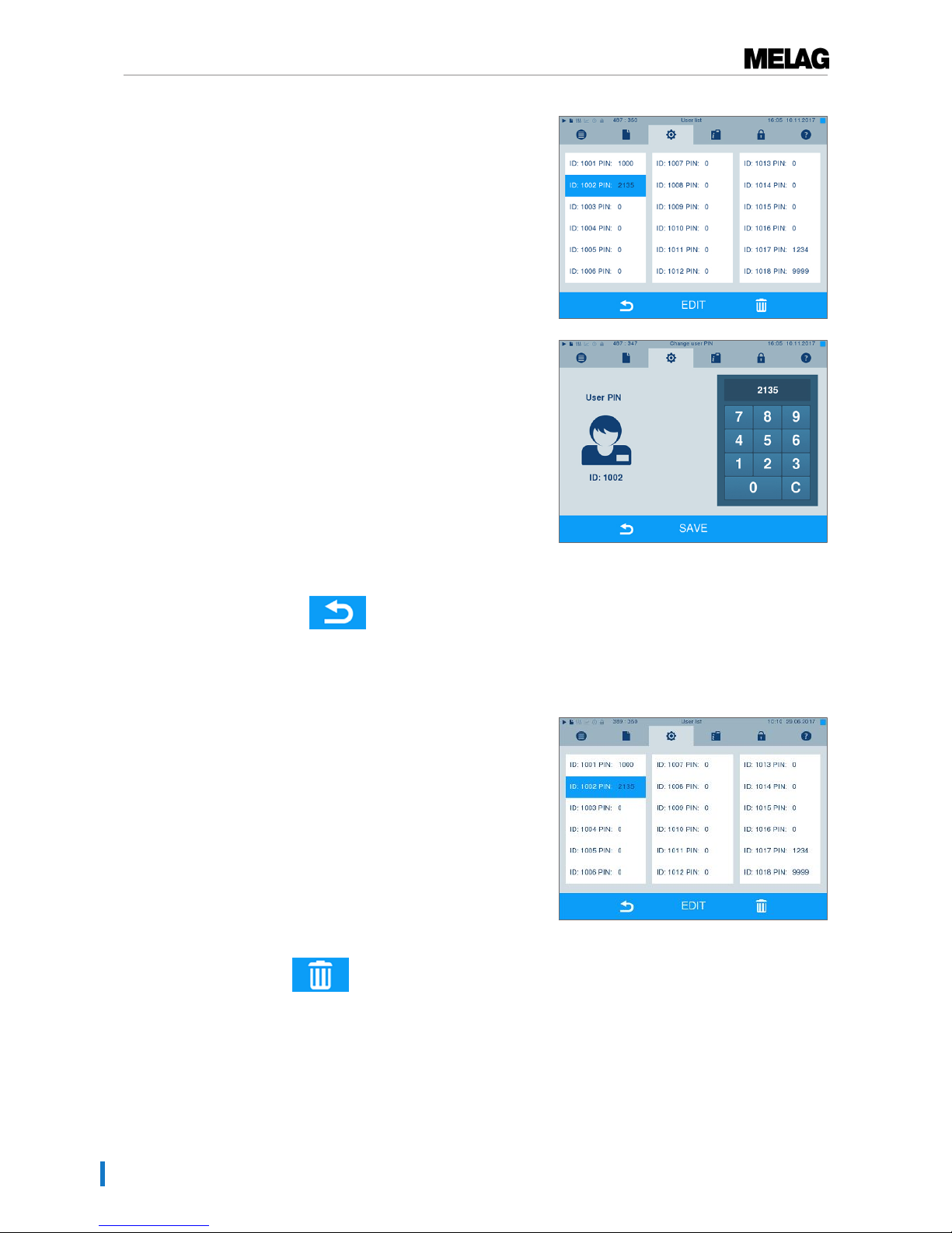
10 Settings
50
4. Select a free ID and select EDIT in order to create a
new user. The first ID is reserved for the Admin PIN.
5. Enter a 4-digit PIN in the right-hand key pad for the
selected User ID.
6. Accept all the settings with SAVE and then leave
the menu.
7. Pressing the symbol enables you to leave
the menu.
Deleting a user
1. Select theUser administration option as
described above and open the user list.
2. Select the User ID which you wish to delete.
3. Press the symbol to delete this menu.
Ê A warming is issued.
4. Confirming the warning with YES will set the PIN
number of this ID to “0”.
Ê A new PIN can be issued for this user ID at any
time.
Page 51
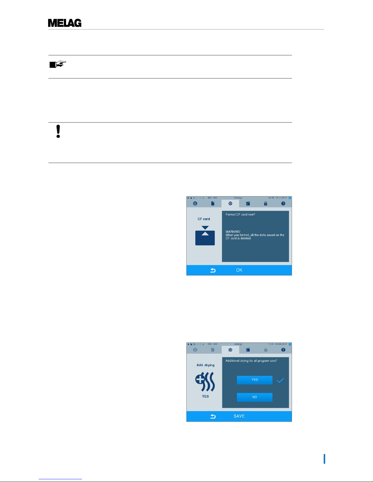
10 Settings
51
Changing the Admin PIN
PLEASE NOTE
If you forget the Admin PIN, consult your stockist/MELAG customer services provider.
The Admin PIN (standard: 1000) can be edited like every other User PIN and should be changed after
delivery.
Formatting the CF card
NOTICE
All data saved on the CF card is deleted during formatting.
n Check whether important data is stored on the CF card.
n Save any logs or other data on the computer or another memory medium.
1. Insert the CF card in the steam sterilizer card slot
correctly (tangible raised bar on the edge pointing
back right). Do not use force.
2. Select theSettings → Format CF card. The
display switches to the corresponding window.
3. To start formatting, press the OK button. Confirm
the security query with YES. You can remove the
CF card as soon as formatting has been completed.
Additional drying
Selecting additional drying extends the drying time of conventional drying by 50 %. Activating intelligent
drying restricts the criteria for ending the drying phase.
1. SelectSettings →Additional drying. The
display switches to the settings window.
2. Press YES or NO, to chose whether additional
drying should be performed during the next
program run.
Page 52
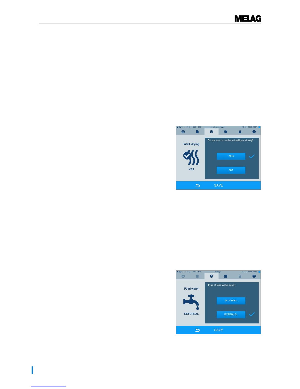
10 Settings
52
3. Confirm with SAVE.
Intelligent drying
In contrast to a conventional time-controlled drying procedure, with which the duration of the drying phase
is determined by the program, the duration of the intelligent drying is automatically calculated using the
residual moisture in the sterilization chamber. A number of factors play a role in this process including e.g.
the nature of the load, wrapped or unwrapped, the load quantity, the distribution of the load in the
sterilization chamber etc. Comply with the specifications in section Loading the steam sterilizer [}page
23].
Intelligent drying is activated in the delivery state. Should you wish to deactivate intelligent drying, proceed
as follows:
1. Select theSettings →Device settings
→Intelligent drying . The display switches
to the corresponding window.
2. If you wish to deactivate intelligent drying, select NO.
3. Confirm with SAVE.
Water supply
Select the corresponding setting in the display, depending on whether the feed water supply is effected
using the internal storage tank or a water treatment unit:
1. Select theSettings menu.
2. Navigate toDevice settings → Water
supply.
Ê The display switches to theWater supply
window.
3. Select INTERNAL, if the supply is to be performed via
the internal storage tank or EXTERNAL, if you have
connected a water treatment unit. NOTICE!When
connecting an external feed water supply it is
necessary to connect an external waste water
outflow as well. There is a risk that hot waste
water might run through the emergency overflow.
4. Confirm with SAVE.
Page 53
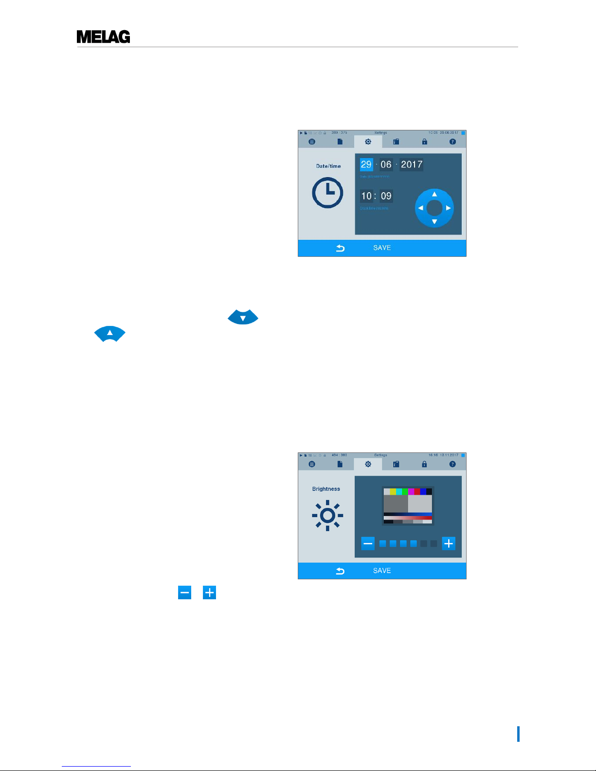
10 Settings
53
Date & time
Correct batch documentation requires the correct date and time setting on the steam sterilizer. Ensure that
you take into account the clock change in autumn and summer, as this is not adjusted automatically. Once
the time has been set on the steam sterilizer, it is very accurate. Set the date and time as follows:
1. SelectSettings →Date & time. The display
switches to the settings window.
2. Select the parameters which you wish to change
(day, month, year / hour, minute second). The
marked parameter is depicted light blue, here e.g.
the hour.
3. Change the respective value via the and
pushbuttons. Repeat this step for all the
parameters which you wish to change.
4. Confirm the changes with SAVE.
Ê The display will be restarted after saving and
then changes automatically to the Programs &
Tests menu.
Brightness
1. SelectSettings →Brightness. The display
switches to the settings window.
2. Press the pushbuttons or to adjust the
brightness and contrast on the display.
3. Accept all the settings with SAVE and then leave
the menu.
Page 54
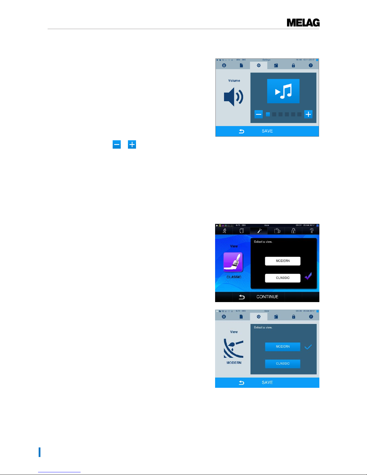
10 Settings
54
Volume
1. SelectSettings →Volume. The display switches
to the settings window.
2. Press the or pushbutton to adjust the
volume.
3. Accept all the settings with SAVE and then leave
the menu.
View
You can choose between classic and modern view.
Switching from CLASSIC TO MODERN
1. Select theSettings →View menu. The display
switches to the settings window.
2. Press the MODERN button. The design changes
immediately.
3. Confirm the settings with SAVE. The display
changes automatically to theSettings.
Page 55
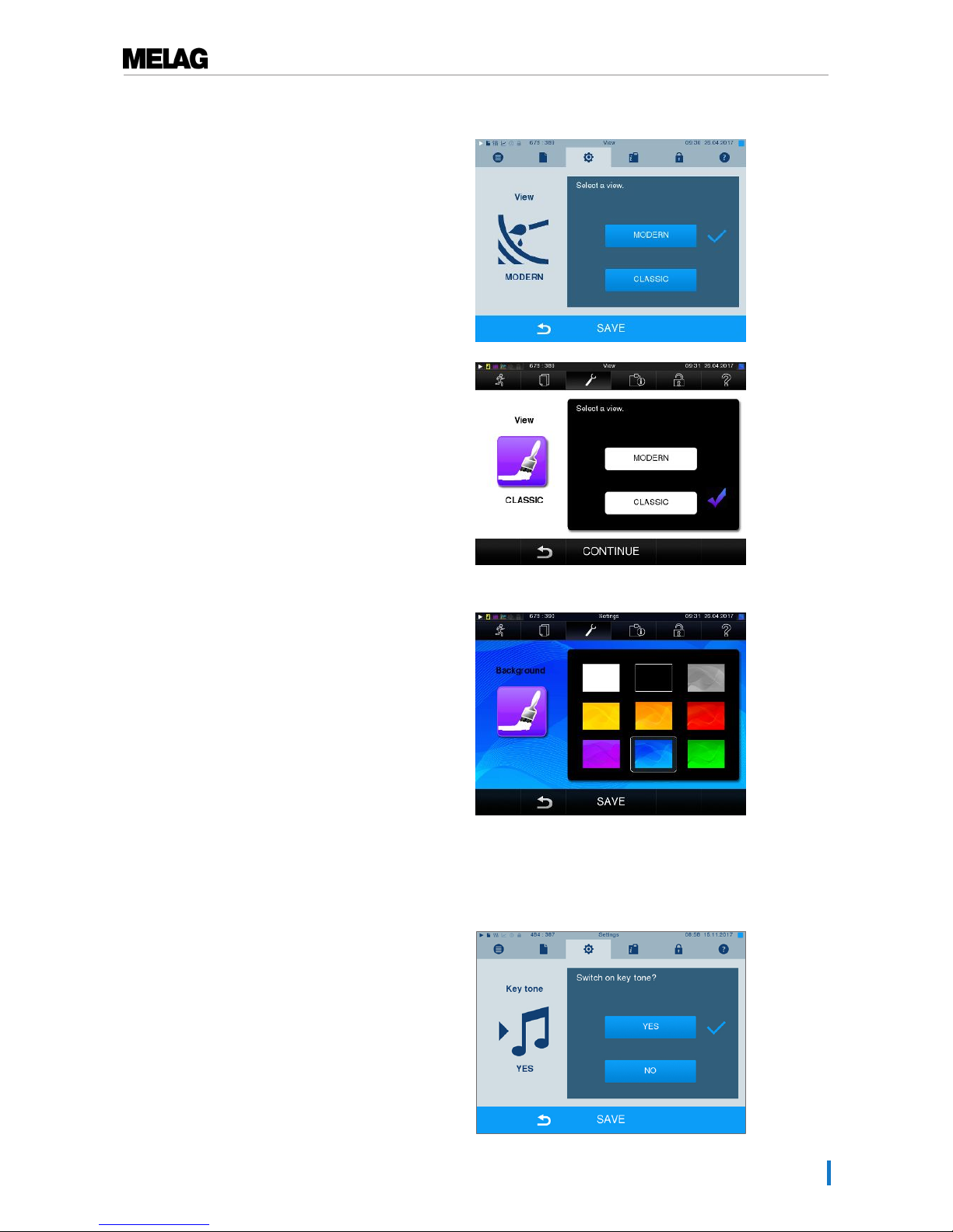
10 Settings
55
Switching from MODERN to CLASSIC
1. Select theSettings →View menu. The display
switches to the settings window.
2. Press the CLASSIC button. The design changes
immediately.
3. Press CONTINUE.
4. Tap on a colour box to change the background colour,
e.g. blue. The background colour changes
immediately and the white frame around the colour
box shows which colour has just been selected.
5. Confirm the settings with SAVE. The display
changes automatically to theSettings menu.
Key tone
1. SelectSettings →Key tone. The display
switches to the settings window.
Page 56
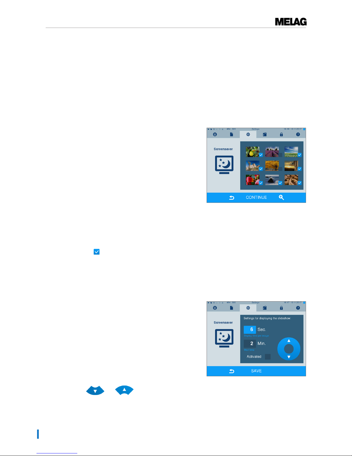
10 Settings
56
2. Press YES or NO to determine whether a tone
should be emitted every time a pushbutton is
pressed. This can be deactivated at any time.
3. Accept all the settings with SAVE and then leave
the menu.
Screensaver
A screensaver can be activated to protect the display in standby operation. This displays a continuous
slide show of any pictures.
Select images for the slide show
1. SelectSettings →Screensaver . The display
switches to the settings window.
2. Tap on a picture to select it. The white frame
around the picture indicates which picture is
currently selected.
3. Repeated tapping on the picture selects/deselects it
for the slide show.
Ê The checkmark on the lower right-hand corner
indicates whether the picture has been
selected for the slide show.
4. Press CONTINUE to make further settings.
Set the display duration of the images and the waiting time of the slide show.
Proceed as follows to alter one of the named options:
1. Select the parameter directly that you wish to change.
The marked parameters are displayed light blue.
2. Change the respective parameter value via the
and pushbuttons.
Page 57
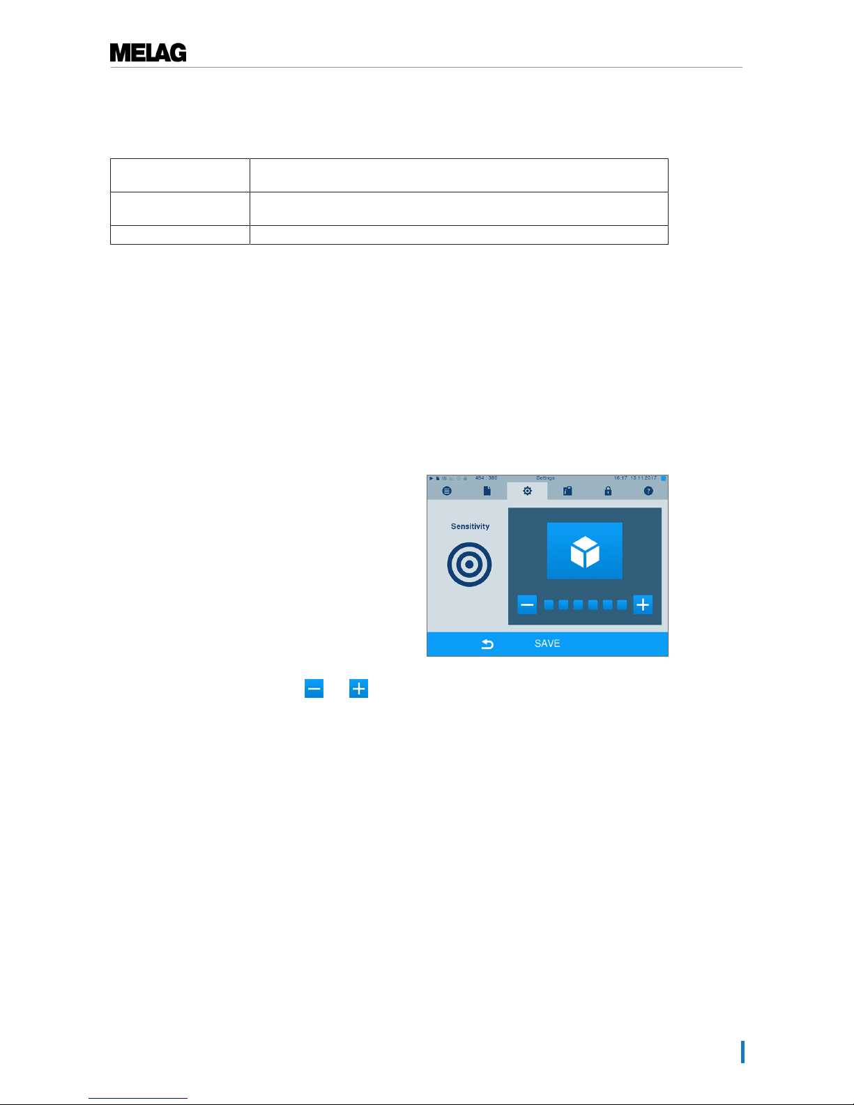
10 Settings
57
3. Confirm the settings with SAVE. The display
switches automatically to the Settings menu.
Table1: Explanation of the slide show options
Display duration per
image
Indicates the time in seconds between the display of two separate pictures.
Waiting time Indicates how long the display remains in normal mode before the slide show
starts.
Activated Setting/unsetting the checkmark activates/deactivates the screensaver.
Log printer MELAprint 42/44
If you wish to output the sterilization log via the log printer MELAprint 42/44, you need to set this on the
steam sterilizer once. The operating manual of the log printer indicates how to set it up.
Label printer MELAprint 60
If you wish to output the sterilization logs via the label printer MELAprint 60, you need to set this on the
steam sterilizer once. The operating manual of the label printer indicates how to set it up.
Sensitivity
1. SelectSettings →Touchscreen
sensitivity. The display switches to the settings
window.
2. You can determine the pressure required to
activate a pushbutton. using the and
pushbuttons.
3. Accept all the settings with SAVE and then leave
the menu.
Energy-saving mode
If the steam sterilizer is not be switched off during longer operating pauses, it can be operated in energysaving mode. This reduces the time which the steam sterilizer requires in order to pre-heat the doublejacket steam generator to the necessary start temperature after deactivation. Two waiting times can be set
in energy-saving mode:
Waiting time 1 (W1): After a re-set waiting time of 15 minutes, the temperature of the double-jacket steam
generator will sink to 103°C. The program run time becomes c. 2 minutes longer upon the next start.
Waiting time (W2): After a pre-set waiting time of 60 minutes, the double-jacket steam generator is no
longer heated. Accordingly, the length of the program run time increases by about 5 minutes upon the next
start, depending on the length of the operating pause, as the double jacket steam generator must first be
pre-heated to the necessary start temperature.
Page 58
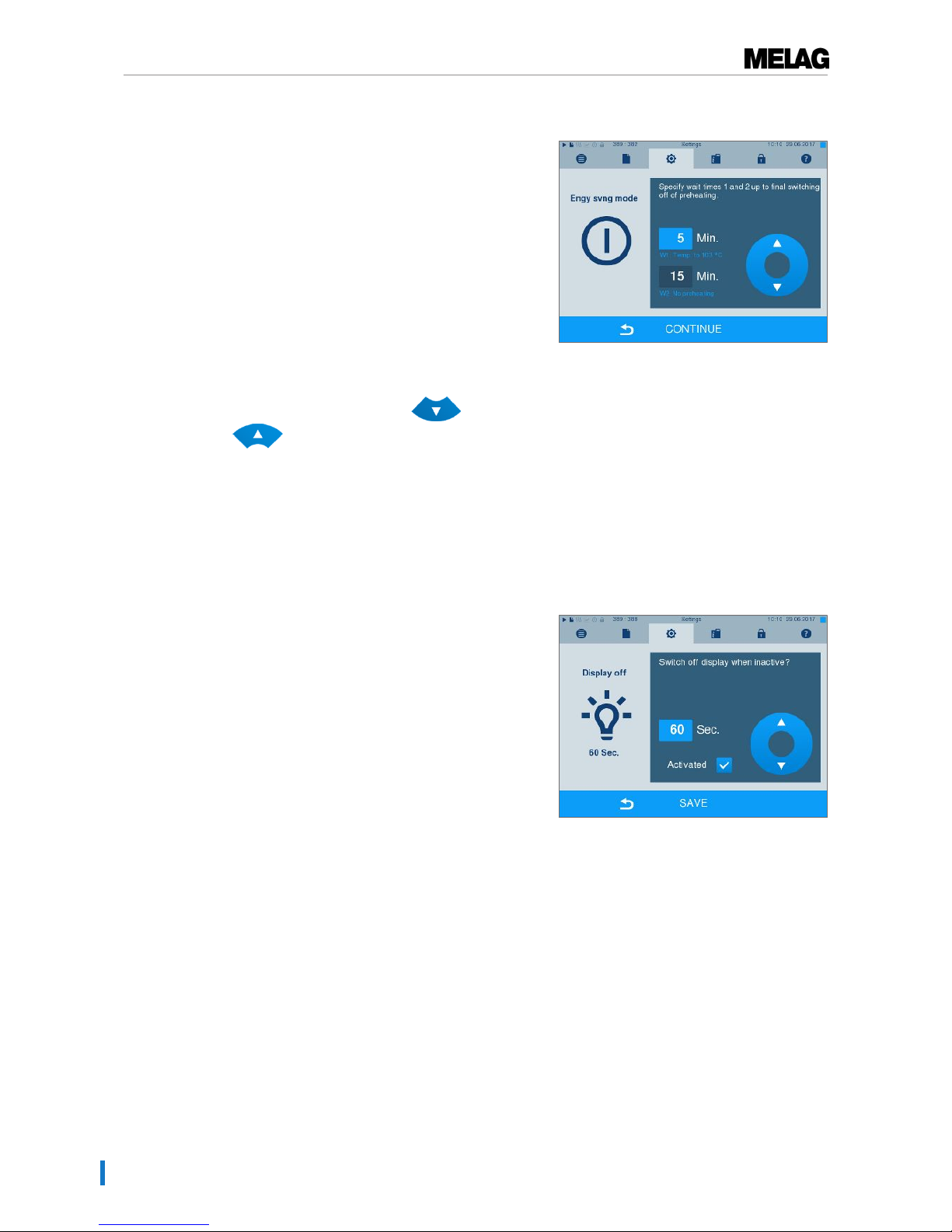
10 Settings
58
Setup of the energy-saving mode is described here:
1. SelectSettings →Energy saving mode. The
display switches to the settings window.
2. Select Waiting time 1 directly by touching the time.
The area is displayed light blue.
3. Change the minutes using the and
pushbuttons.
4. Repeat the step for waiting time 2.
5. Press CONTINUE.
Switching off the display
Optionally, you can choose whether the display is to be switched off when the steam sterilizer is in energysaving mode (waiting time 2).
1. Set the checkmark next to "Activated" and set the
number of seconds after which the display is to be
deactivated.
2. Confirm the settings with SAVE. The display
changes automatically to the Settings menu.
3. You can switch the display back on by touching the
screen.
Page 59
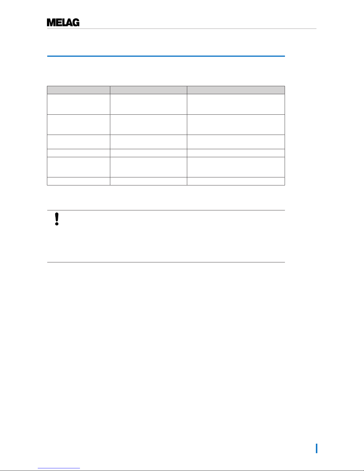
11 Maintenance
59
11 Maintenance
Servicing intervals
Interval Measure Device components
Weekly Check for soiling, deposits or
damage
Chamber inc. door seal and chamber
sealing face,
mount for the load
With every filling of the
storage tank
Check the storage tank for
soiling and clean it if necessary
before filling
Internal storage tank
Every 2 weeks Clean the left-hand chamber of
the storage tank (waste water)
Internal storage tank
After 2 months Oil the door spindle Door mechanism
After 2years or
2000cycles
Maintenance By the authorized customer services
working in accordance with the
maintenance instructions.
As required Cleaning the surfaces Housing parts
Cleaning
NOTICE
Inappropriately performed cleaning can lead to the scratching of and damage to surfaces
and the development of leaks in sealing surfaces.
This also favours the development of soiling deposits and corrosion in the sterilization
chamber.
n Comply with all information regarding cleaning of the part affected.
Door seal, chamber, chamber sealing face, mount, trays
Check the chamber, door seal, chamber sealing face and the load mount once a week for soiling,
deposits or damage.
If you find any impurities, remove the trays or cassettes from the chamber from the front. Clean the soiled
components.
When cleaning the chamber, load mount and chamber seal face, please comply with the following:
u Switch off the steam sterilizer before cleaning and remove the power plug from the socket.
u Ensure that the chamber is not hot.
u Use a soft, non-fuzzing cloth.
u First soak the cloth with cleaning alcohol or spirit and attempt to remove the impurities with this
method.
u Use a chlorine- and vinegar-free cleaning fluid.
u Only if the chamber, mount or chamber seal face has persistent soiling should you use a mild, non-
scouring, stainless steel cleaning agent, with a pH value between 5 and 8.
u Use a neutral liquid cleaning agent to clean the door seal.
u You should not allow cleaning fluid to enter the piping coming from the chamber of the steam sterilizer.
u Do not use any hard objects such as a metal saucepan cleaner or a steel brush.
Page 60
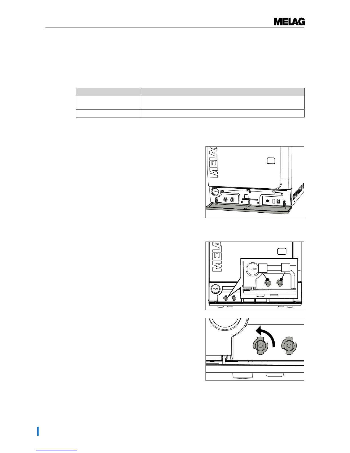
11 Maintenance
60
Housing parts
Where necessary, clean the housing parts with a neutral fluid cleaner or spirit.
Internal storage tank
Should you use the internal storage tank for the feed water supply, perform regular checks and cleaning as
follows:
Interval
Upon every refill Check the storage tank for soiling. If necessary, clean the storage tank with
fresh feed water before filling.
Every 2 weeks Clean the left-hand chamber of the storage tank (waste water).
Empty the chamber of the internal storage tank
1. Open the service hatch in the lower area of the steam
sterilizer.
2. Place a min. 5 L bucket in front of the steam
sterilizer.
3. Connect the drain hose onto one of the drain fittings
on the waste water side (pos. a) or the feed water side
(pos. b) until it snaps into place. The knob must be
vertical.
b
a
4. Open the water drain tap by turning the knob 1/4 in an
anti-clockwise direction.
5. To remove the drain hose, turn the hose connection
into the vertical position.
Page 61
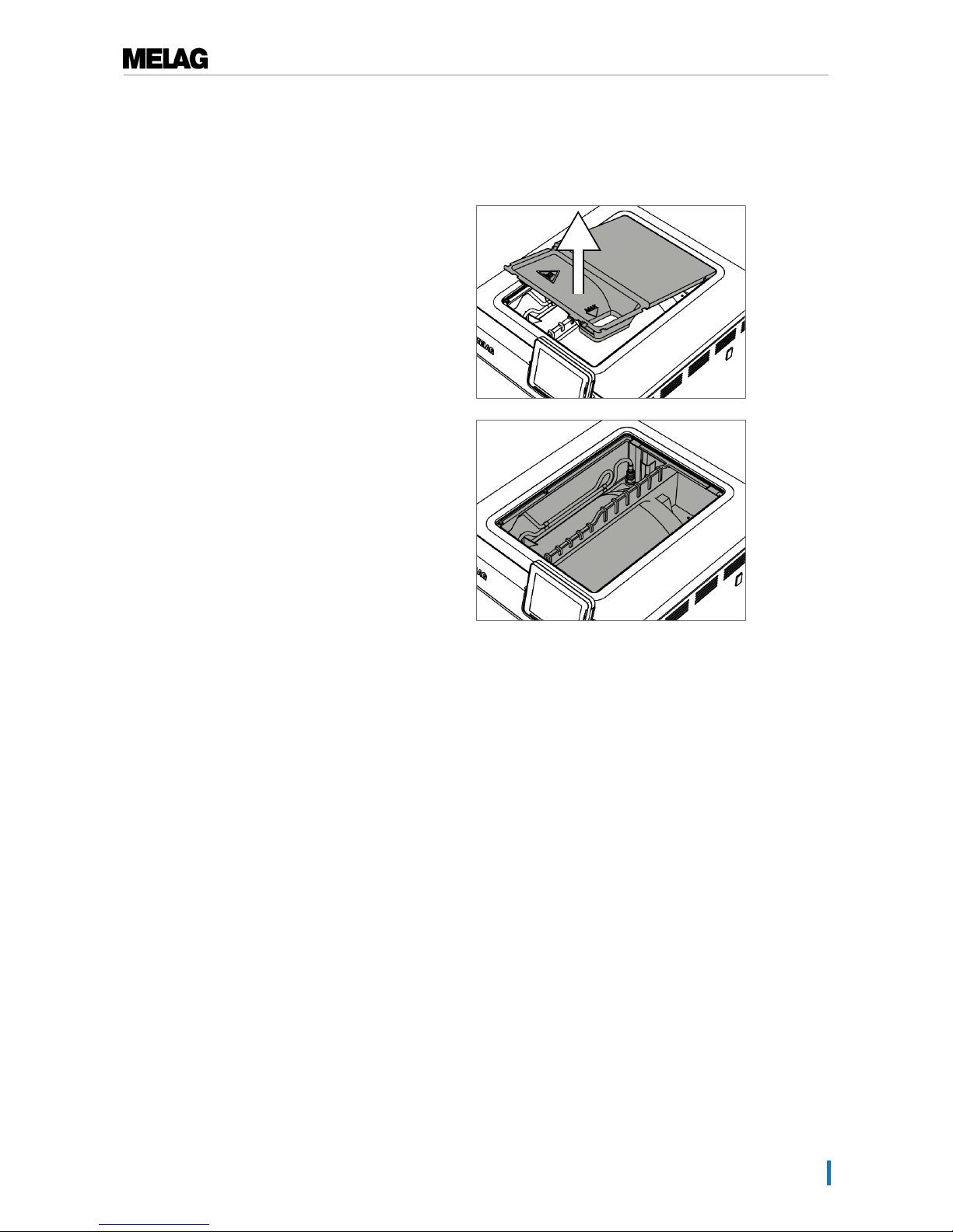
11 Maintenance
61
Cleaning the feed and waste water side
You can remove the cover of the storage tank completely to clean the chambers of the internal storage
tank.
1. Remove the fore tank lid.
2. Grasp the cover on the filling opening and then lift the
cover upwards a little.
3. Remove the cover from the rubber seal completely.
Avoiding staining
Only after cleaning instruments properly prior to sterilization is it possible to avoid residue from the load or
the instrument decontamination from being released during sterilization. Loosened dirt residue can clog
the filter, nozzles and valves of the steam sterilizer and deposit themselves on the instruments and
chamber as deposits and stains.
All steam-conducting parts of the steam sterilizer consist of non-rusting material. This rules out the
possibility of stain or rust development being caused by the steam sterilizer. The development of rust is
always extraneous rust.
Incorrect instrument decontamination can result in the accretion of rust even on stainless steel instruments
of leading manufacturers. Often, an instrument which drops rust can suffice to cause the development of
rust on another instrument or in the steam sterilizer. Remove foreign rust from the instruments using a
chlorine-free stainless steel cleaning agent (see section Cleaning [}page 59]) or send the damaged
instruments to the manufacturer.
The extent of stain accretion on the instruments is also dependant on the feed water used for steam
generation.
Oiling the door spindle
Oil the door spindle every two months as follows:
1. Clean the spindle with a non-fuzzing cloth.
2. Place two drops of oil in the bushing on the door of the steam sterilizer from the oil can included in the
scope of delivery (art. no. 27515).
Instructions for oiling the door spindle are printed on the inside of the door of the steam sterilizer.
Page 62

11 Maintenance
62
Maintenance
NOTICE
Continuing operation beyond the maintenance interval can result in malfunctions in the
device.
n Maintenance should only be performed by trained and authorized customer services
technicians, or stockist technicians.
n Maintain the specified servicing intervals.
Regular maintenance is vital to ensure reliable operation and value retention of the steam sterilizer. All
function and safety-relevant components and electrical units must be checked during maintenance and
replaced where necessary. Maintenance is performed in accordance with the maintenance instructions
pertinent to this steam sterilizer.
Have maintenance carried out regularly after 2000 program cycles, but no later than 24 month. The steam
sterilizer will issue a maintenance message at the relevant time.
Page 63
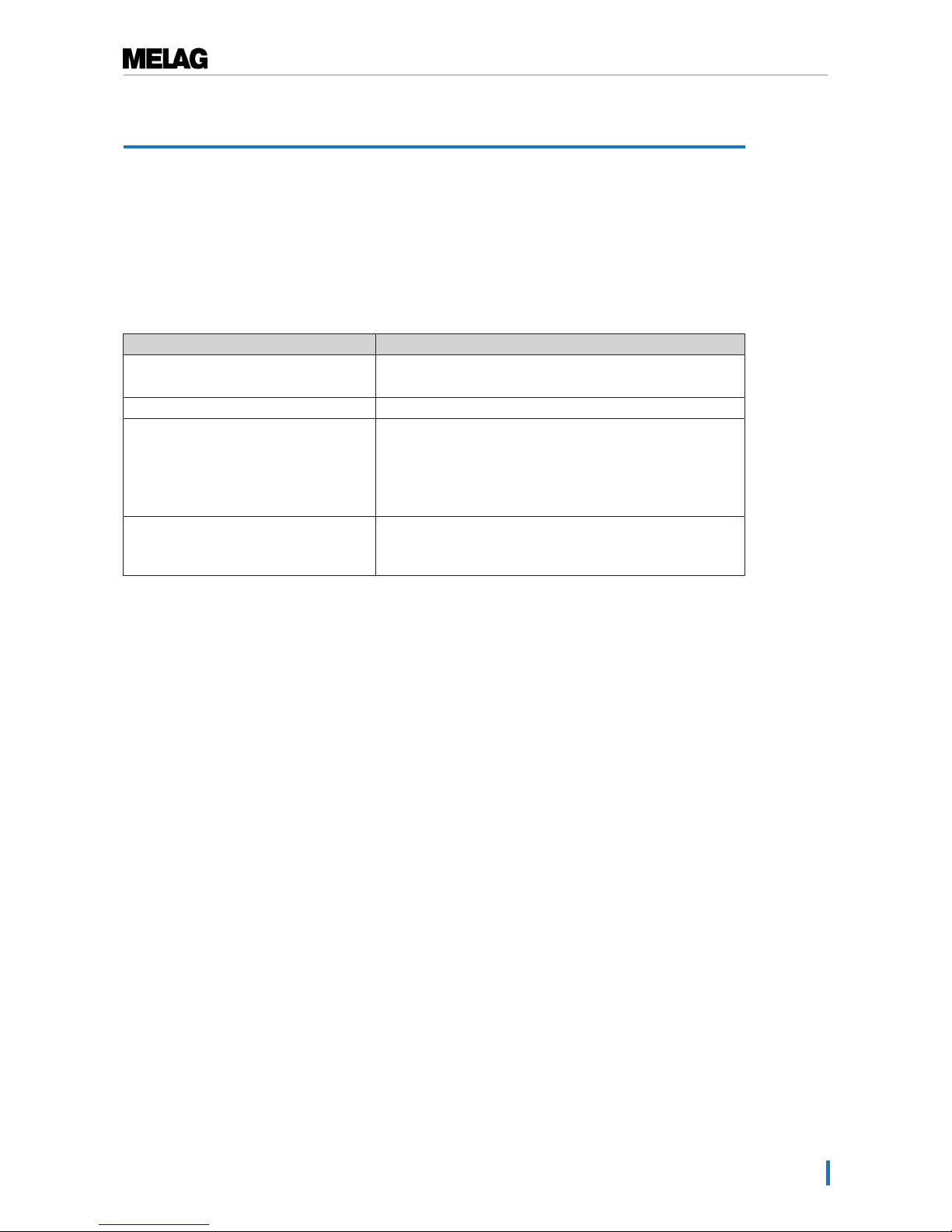
12 Pause times
63
12 Pause times
Frequency of sterilization
Pause times between the individual programs are not necessary, as the sterilization chamber is
maintained permanently at the same temperature. After the end/abort of the drying time and removal of the
sterilized equipment, you can load the steam sterilizer again and start a new program.
Operating pauses
Duration of the operating pause Measure
Short pauses between two sterilization
processes
▪ Keep the door closed to save energy
▪ Set the energy-saving mode correspondingly
Pauses which last longer than an hour ▪ Switch off the steam sterilizer
Longer pauses e.g. over night or the
weekend
▪ Switch off the steam sterilizer
▪ Push the door to, to prevent premature wear and the
sticking of the door seal.
▪ If present, shut off the water inflow of the water treatment
unit
Longer than two weeks ▪ Perform a vacuum test.
▪ After a successful vacuum test, perform an empty
sterilization run in Quick-Program S
After pauses, perform the checks described in chapter Function tests depending on the length of pause
Decommissioning
When decommissioning the steam sterilizer for a long pause (e.g. due to holiday), proceed as follows:
1. Empty the double jacket steam generator, see Emptying the double jacket [}page 63].
2. Switch off the steam sterilizer at the power switch.
3. After deactivating, wait until the pressure display manometer of the deactivation pressure shows 0
bar.
4. Remove the power plug from the socket and if necessary, allow the steam sterilizer to cool.
5. Empty the internal storage tank.
6. Shut off if present, the water inflow of the water treatment unit.
Emptying the double jacket
You have the option of draining the water in the double jacket steam generator easily via the Draining
program. In order to do so, the steam sterilizer is heated once, building up pressure in the double-jacket so
that the water can be drained fully from the double jacket steam generator.
1. Switch on the steam sterilizer at the power switch.
Page 64
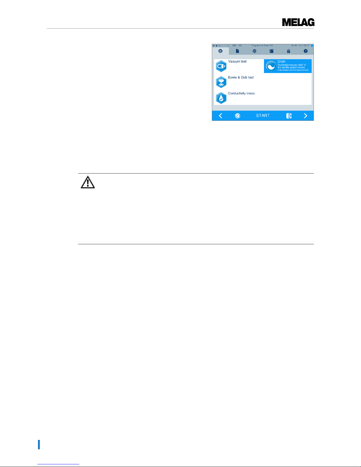
12 Pause times
64
2. Working in thePrograms & Tests menu, select
the Draining program and press START.
3. Switch off the steam sterilizer in the program end
window "Draining successful" so that the steam
sterilizer does not feed water back into the double
jacket.
Transport
CAUTION
Danger of injury from incorrect carrying.
Lifting and carrying too heavy a load can result in spinal injury. Failure to comply with
these provisions can result in crushing.
n The device should always be carried by two people.
n Use the suitable carrying straps to carry the device.
n Please note that the distance between the base plate and the setup surface is low.
n Please ensure that you comply with the transport instructions.
Please comply with the following during transport, within a room or the practice:
u Decommission the steam sterilizer, see: Decommissioning [}page 63].
u Remove the connection hoses connected on the rear of the device.
u Should you wish to leave the mount and trays or cassettes in the chamber during transport, protect the
surface of the round blank. To do so, place some foam or bubble wrap between the round blank and
mount.
u Close the steam sterilizer door before moving it.
Transport within the practice
Please comply with the following during transport, within a room or the practice:
u Decommission the steam sterilizer, see section Decommissioning [}page 63].
u Remove the connection hoses connected on the rear of the device.
u Should you wish to leave the mounts and tray or cassettes in the chamber during transport, protect the
surface of the round blank. To do so, place some foam or bubble wrap between the round blank and
mount.
u Close the steam sterilizer door before moving it.
Transport over long-distance / dispatch
For transport over longer distances, during the danger of frost and / for despatch or during maintenance,
an authorized person must prepare the steam sterilizer according to instructions and empty the doublejacket steam generator entirely.
Page 65

12 Pause times
65
Recommissioning after relocation
When recommissioning after a move, proceed as with the first commissioning; see technical manual.
Page 66
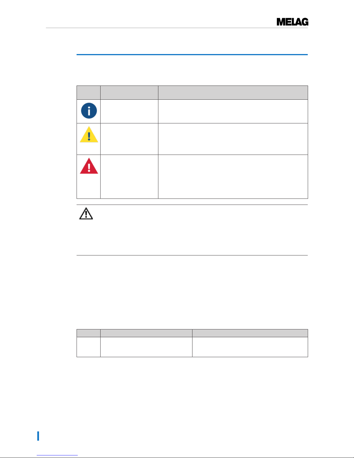
13 Malfunctions
66
13 Malfunctions
Not all notifications on the display are malfunction messages. Warnings and malfunction messages are
issued on the display with an event number. This number serves identification purposes.
Type of the display
notification
Explanation
Messages A number of notifications are messages providing information.
Messages are not malfunction messages or warnings. They support
the operation of the steam sterilizer.
Warnings Warning messages are displayed when necessary. These contain
instructions which apply to you, the operator. Warning messages
are not malfunction messages. They help to ensure malfunctionfree operation and to recognize undesirable situations. Comply with
these warnings early in order to avoid malfunctions.
Malfunction messages Malfunction messages are issued when it is not possible to ensure
safe operation or safety of sterilization. These can appear on the
display shortly after switching on the device or during a program
run. If a fault occurs during a program run, the program will be
aborted. Aborting a program before the drying phase means that
the load is unsterile. If necessary, repack the load and repeat the
sterilization for the sterilization material affected.
WARNING
Danger of infection from early program abort
Aborting a program before the drying phase begins means that the load is unsterile. This
endangers the health of your patients and practice team.
n If necessary, repack the load and repeat the sterilization for the sterilization material
affected.
Before contacting customer services
Ensure that you have complied with all instructions relating to a warning or malfunction message issued on
the display of the steam sterilizer. The following table contains a summary of the most important events.
Should you be unable to find the relevant event in the table below, or your efforts do not redress the
problem, you can contact your nearest stockist or an authorized MELAG customer service provider. To
enable us to give the best possible service, please have your steam sterilizer serial number and a detailed
description of the fault to hand.
Messages
Incident Possible causes What you can do
M248 The vacuum test was performed, despite
residual moisture in the chamber or with
a load.
Repeat vacuum test, when steam sterilizer is cold
and empty
Page 67
13 Malfunctions
67
Warning and error messages
Incident Possible causes What you can do
62 When using the internal storage tank:
a) Insufficient feed water in the right-hand
chamber of the internal storage tank.
b) The float switch of the right-hand chamber
of the internal storage tank (feed water) is
stuck.
a) Check whether there is sufficient feed
water in the right-hand chamber of the
internal storage tank and refill with feed
water if necessary.
b) Check the float switch as follows:
1. Remove the tank lid from the storage tank.
2. Remove the filling funnel if present.
3. Move the float in the right-hand chamber
of the storage tank (feed water side from
below in the tank) up and down repeatedly to
restore its free-movement.
When using a MELAG water treatment unit:
c) The feed water supply in the device has
been set to "INTERNAL".
When using a MELAG water treatment unit:
to c) Set the feed water supply in the
“Settings” menu (function) to
"EXTERNAL” (see Water supply [}page
52]).
63 Very poor feed water quality (conductivity ≥ 65 µS).
When using the internal storage tank:
a) Water of insufficient quality e.g. tap water
was used.
a) Empty and clean the right-hand chamber
of the internal storage tank (feed water side)
and fill it with water of the required quality
(DIN EN 13060, Appendix C).
When using a MELAG water treatment unit:
b) MELAdem 40: The mixed-bed resin
cartridge is exhausted.
c) MELAdem 47: The mixed-bed resin
cartridge, the pre-filter or the activated coal
filter is exhausted.
b) MELAdem 40: Replace the mixed-bed
resin cartridge in accordance with the
applicable operating manual.
c) MELAdem 47: Replace the mixed-bed
resin cartridge and if necessary, the pre-filter
and activated carbon filter in accordance with
the applicable operating manual. Empty the
pressure tank (if possible until it is half full)
and wait until it has been filled again. An
empty pressure tank requires c. 1 hour to fill.
Please note: The notification may also
continue to be shown after the filter has been
changed until the water remaining in the
storage tank has been consumed.
64 see event 63
65 see event 63
66 The feed water inflow line between the water
treatment unit and the steam sterilizer has a
leak. Air is also taken in.
When using a MELAG water treatment unit:
Check whether the feed water inflow line to
the steam sterilizer has any leaks and has
been connected correctly.
67 Only when using a water treatment unit:
The waste water cannot flow off. A rinse
must be performed after a further 2 or 3
program runs.
a) The waste water hose is kinked or
installed sagging.
b) The siphon or the building-side waste
water line is blocked.
c) The Quick-Program B and S are mainly
used. These programs do not do not have
automatic rinsing.
a) Check the installation of the waste water
hose. This must be installed without kinking
or sagging and at a constant decline.
b) Check whether the building siphon is
blocked. Please note: If multiple devices are
operated simultaneously, we recommend the
installation of an additional siphon.
c) Start another program e.g. the UniversalProgram, Gentle-Program or Prion-Program
to perform the necessary rinsing.
Page 68

13 Malfunctions
68
Incident Possible causes What you can do
71 When using the internal storage tank:
a) Insufficient feed water in the right-hand
chamber of the internal storage tank.
b) The float switch of the right-hand chamber
of the internal storage tank (feed water) is
stuck.
When using a MELAG water treatment unit:
c) The water supply is set to “INTERNAL"
despite external water supply.
When using the internal storage tank:
a) Check the water level of the feed water in
the right-hand chamber of the internal
storage tank and refill with feed water if
necessary.b) Check the float switch as
follows:
1. Remove the tank lid from the storage tank.
2. Remove the filling funnel if present.
3. Move the float in the right-hand chamber
of the storage tank (feed water side from
below in the tank) up and down repeatedly to
restore its free-movement.
When using a MELAG water treatment unit:
c) Set the feed water supply in the “Settings”
menu (function) to "EXTERNAL” (see Water
supply [}page 52]).
72 Poor feed water quality (conductivity ≥ 40 µS).
When using the internal storage tank:
a) Water of insufficient quality e.g. tap water
was used.
a) Empty and clean the right-hand chamber
of the internal storage tank (feed water side)
and fill it with water of the required quality
(DIN EN 13060, Appendix C).
When using a MELAG water treatment unit:
b) MELAdem 40: The mixed-bed resin
cartridge is exhausted.
c) MELAdem 47: The mixed-bed resin
cartridge, the pre-filter or the activated coal
filter is exhausted.
b) MELAdem 40: Replace the mixed-bed
resin cartridge in accordance with the
applicable operating manual.
c) MELAdem 47: Replace the mixed-bed
resin cartridge and if necessary, the pre-filter
and activated carbon filter in accordance with
the applicable operating manual. Empty the
pressure tank (if possible until it is half full)
and wait until it has been filled again. An
empty pressure tank requires c. 1 hour to fill.
Please note: The notification may also
continue to be shown after the filter has been
changed until the water remaining in the
pressure tank has been consumed.
73 see event 72
74 Poor feed water quality (conductivity ≥ 40 µS).
When using the internal storage tank:
a) Insufficient feed water in the right-hand
chamber of the internal storage tank.
b) The float switch of the right-hand chamber
of the internal storage tank (feed water) is
stuck.
a) Check the water level of the feed water in
the right-hand chamber of the internal
storage tank and refill with feed water if
necessary.
b) Check the float switch as follows:
1. Remove the tank lid from the storage tank.
2. Remove the filling funnel if present.
3. Move the float in the right-hand chamber
of the storage tank (feed water side from
below in the tank) up and down repeatedly to
restore its free-movement.
When using a MELAG water treatment unit:
c) The water supply is set to “INTERNAL"
despite external water supply.
When using a MELAG water treatment unit:
c) Set the feed water supply in the “Settings”
menu (function) to "EXTERNAL” (see Water
supply [}page 52]).
Page 69
13 Malfunctions
69
Incident Possible causes What you can do
75 When using the internal storage tank:
a) Insufficient feed water in the right-hand
chamber of the internal storage tank.
b) The float switch of the right-hand chamber
of the internal storage tank (feed water) is
stuck.
a) Check the water level of the feed water in
the right-hand chamber of the internal
storage tank and refill with feed water if
necessary.
b) Check the float switch as follows:
1. Remove the tank lid from the storage tank.
2. Remove the filling funnel if present.
3. Move the float in the right-hand chamber
of the storage tank (feed water side from
below in the tank) up and down repeatedly to
restore its free-movement.
When using a MELAG water treatment unit:
c) The water supply is set to “INTERNAL"
despite external water supply.
When using a MELAG water treatment unit:
c) Set the feed water supply in the “Settings”
menu (function) to "EXTERNAL” (see Water
supply [}page 52]).
76 a) The Quick-Program B and S are mainly
used. These programs do not do not have
automatic rinsing.
With connection to the building waste water
outflow:
The waste water cannot flow off. A rinse
must be performed after a further 2 or 3
program runs.
b) The waste water hose is kinked or
installed sagging.
c) The siphon or the building-side waste
water line is blocked.
a) Start another program e.g. the UniversalProgram, Gentle-Program or Prion-Program
to perform the necessary rinsing.
With connection to the building waste water
outflow:
b) Check the installation of the waste water
hose. This must be installed without kinking
or sagging and at a constant decline.
c) Check whether the building siphon is
blocked. Please note: If multiple devices are
operated simultaneously, we recommend the
installation of an additional siphon.
78 a) The left-hand chamber of the internal
storage tank (waste water) is full or was only
incompletely emptied.
b) If the notification is displayed despite an
empty tank, the float switch is blocked.
a) Empty the left-hand chamber of the
storage tank (waste water).
b) Check the float switch as follows:
1. Remove the tank lid from the storage tank.
2. Remove the filling funnel if present.
3. Move the float in the left-hand chamber of
the storage tank (feed water side from below
in the tank) up and down repeatedly to
restore its free-movement.
80 see event 78
81 a) The door was not pushed closed for long
enough with sufficient force; as a result, the
thread has become caught.
b)The door spindle and/or the door lock nut
were not oiled regularly and are dry.
a) Close and hold the door with force for c. 3
seconds until the spindle engages in the
door lock and the door is pulled in
automatically. A motor sound is audible.
b) Lubricate the door spindle and the door
lock nut regularly with the oil included in the
scope of delivery (see Oiling the door spindle
[}page 61]).
82 a) There are objects in the door area.
b) A residual vacuum is present in the
sterilization chamber. The pressure
equalization has not been concluded.
c) The door seal sticks to the seal face of the
sterilization chamber.
a) Always keep the area in front of the door
free so that it can open unhindered.
b) 1. Wait two minutes and then confirm the
notification with OK.
2. Should the door not open independently,
switch off the steam sterilizer, wait five
minutes and then switch it back on. Try again
to open the door.
If the door does not open, inform the
authorized customer services/stockist
technician.
c) If the door could be opened, clean the
door seal and the seal face in the sterilization
chamber (see Cleaning [}page 59]).
Page 70
13 Malfunctions
70
Incident Possible causes What you can do
83 The door does not reach a pressure-tight
state after the program start.
a) The door seal and/or the seal face is
soiled and or damaged.
b) The load blocks the door area.
c) The closing mechanism is stiff.
a) Check the door seal and the seal face in
the sterilization chamber for soiling, foreign
bodies or damage.
b) Check whether the load is blocking the
door.
c) Check the door spindle and the door lock
nut for damage. Clean and oil the door
spindle and the door lock nut with the oil
included in the scope of delivery. Clean and
oil the door spindle and the door lock nut
with the oil included in the scope of delivery
(see Oiling the door spindle [}page 61]).
84 see event 82
86 The door has not been closed correctly upon
program start.
Close and hold the door with force for c. 3
seconds until the spindle engages in the
door lock and the door is pulled in
automatically. A motor sound is audible.
89 see event 86
102 a) The chamber filter “Pressure release” is
blocked.
a) Remove the "Pressure release” chamber
filter (in the rear area of the sterilization
chamber below) and check whether it is e.g.
soiled/blocked by packaging. If necessary,
clean the chamber filter.
With connection to the building waste water
outflow:
The waste water cannot flow off.
b) The waste water hose is kinked or
installed sagging.
c) The siphon or the building-side waste
water line is blocked.
With connection to the building waste water
outflow:
b) Check the installation of the waste water
hose. This must be installed without kinking
or sagging and at a constant decline.
c) Check whether the building siphon is
blocked. Please note: If multiple devices are
operated simultaneously, we recommend the
installation of an additional siphon.
103 The sterile filter is soiled/blocked. 1. Check whether the sterile filter suction
aperture (centre aperture) on the rear panel
of the steam sterilizer is blocked. If yes,
replace the sterile filter.
2. If nothing can be recognized, remove the
sterile filter on the rear panel of the steam
sterilizer and perform a program run without
a load. If the program has been ended
successfully, the sterile filter is blocked. In
this case, replace the sterile filter.
104 see event 103
110 a) The steam sterilizer is overloaded or the
load has been arranged badly.
b) The mains voltage is too low, poor
building voltage supply (e.g. undersized
installation, defective socket, multiple
devices on a single socket/fuse).
a) Comply with the maximum permissible
load quantities (see Loading the steam
sterilizer [}page 22]). Ensure that the load
does not come into direct contact with or
covers the steam injection nozzles.
b) Check the building-side socket / test the
steam sterilizer using a different socket or
circuit.
111 see event 110
Page 71
13 Malfunctions
71
Incident Possible causes What you can do
113 a) The steam sterilizer was switched off at
the power switch during a program run.
b) The power plug has been disconnected or
has not been connected correctly in the
socket.
c) Power outage in the building supply or the
building-side RCD switch has tripped.
a) Never switch off the steam sterilizer at the
power switch during a program run.
b) Check whether the power plug is
connected, the power cable has suffered
damage or a loose contact or loose plug
connections is the cause. Plug the power
plug back into the mains socket.
c) Arrange for an inspection of the buildingside installation (e.g. automatic circuit
breaker) and test the steam sterilizer at
another socket or on another circuit.
114 see event 78
124 a) The surrounding temperature of the steam
sterilizer is too hot.
b) The minimum clearance to the
surrounding surfaces has not been
maintained. The steam sterilizer receives no
or insufficient cooling air.
c) The steam sterilizer is overloaded.
d) The steam sterilizer was operated without
an insert rack and the load (especially the
textiles) comes into direct contact with the
chamber wall.
e) The openings for suction of the cooling air
on the underside of the steam sterilizer are
covered.
f) The chamber filter “Vacuum” is soiled/
blocked.
a) The ambient temperature must be below
40 °C. We recommend a maximum
temperature of 25 °C.
b) Maintain a minimum clearance to the
surrounding surfaces (see information in the
technical manual).
c) Comply with the maximum permissible
load quantities (see Selecting the program
[}page 26]). If necessary, perform a vacuum
test.
d) Always operate the steam sterilizer with
an insert rack and comply with the loading
information (see Loading the steam sterilizer
[}page 22]).
e) Check whether the cooling air suction
openings in the underside of the steam
sterilizer are covered and remove any
objects obscuring them e.g. paper or
packaging.
f) Remove the "Vacuum” chamber filter (in
the rear area of the sterilization chamber
below) and check whether it is e.g. soiled/
blocked by packaging. If necessary, clean
the chamber filter.
125 see event 124
126 see event 124
127 see event 124
131 a) The waste water hose is kinked or
installed sagging.
b) The siphon is blocked or the waste water
line is impeded on the building side.
c) Multiple devices have been connected to a
single siphon and imped each other during
water discharge.
d) The chamber filter "Pressure release" is
blocked.
a) Check the installation of the waste water
hose. This must be installed without kinking
or sagging and at a constant decline.
b) Check whether the building siphon or the
waste water line is are blocked.
c) If multiple devices are operated
simultaneously, we recommend the
installation of an additional siphon.
d) Remove the "Pressure release” chamber
filter and check whether it is soiled/blocked
by packaging If necessary, clean the
chamber filter.
133 see event 124
Page 72
13 Malfunctions
72
Incident Possible causes What you can do
136 a) The surrounding temperature of the steam
sterilizer is too hot.
b) The ventilation slots in the side walls are
clogged/blocked.
c) The steam sterilizer is installed. The
minimum clearance to the surrounding
surfaces has not been maintained.
d) The door was left open after loading or
unloading and hot steam has escaped from
the sterilization chamber.
Switch off the steam sterilizer and allow it to
cool for c. 1 hour.
a) Comply with the requirements at the
installation location and the maximum
ambient temperature (see technical manual).
b) Clean the ventilation slots and remove any
objects covering them.
c) Maintain a minimum clearance to the
surrounding surfaces (see information in the
technical manual).
d) Always close the door after loading or
unloading.
175 The overheat control switch of the main
heating has tripped. This notification may be
issued in alternation with “E176: ACOUT 02
open".
1. Switch off the steam sterilizer and press
the reset button overheat control on the fore
side of the steam sterilizer at the bottom
right-hand side (behind the cover) back in.
2. Acknowledge the malfunction message.
3. Switch off the steam sterilizer and back on
again and then perform an empty sterilization
run if necessary. Then the steam sterilizer is
ready for operation.
176 The overheat control switch of the main
heating has tripped. This notification may be
issued in alternation with “E175: ACOUT 01
open".
1. Switch off the steam sterilizer and press
the reset button overheat control on the fore
side of the steam sterilizer at the bottom
right-hand side (behind the cover) back in.
2. Acknowledge the malfunction message.
3. Switch off the steam sterilizer and back on
again and then perform an empty sterilization
run if necessary. Then the steam sterilizer is
ready for operation.
182 The mains voltage is too low, poor building
voltage supply (e.g. undersized installation,
defective socket, multiple devices on a single
socket/fuse).
Arrange for an inspection of the building-side
installation (e.g. automatic circuit breaker)
and test the steam sterilizer at another
socket or on another circuit.
183 see event 124
185 see event 110
186 see event 110
187 a) The chamber filter “Pressure release” is
blocked.
a) Remove the "Pressure release” chamber
filter (in the rear area of the sterilization
chamber below) and check whether it is e.g.
soiled/blocked by packaging. If necessary,
clean the chamber filter.
With connection to the building waste water
outflow:
The waste water cannot flow off.
b) The waste water hose is kinked or
installed sagging.
c) The siphon or the building-side waste
water line is blocked.
With connection to the building waste water
outflow:
b) Check the installation of the waste water
hose. This must be installed without kinking
or sagging and at a constant decline.
c) Check whether the building siphon is
blocked. Please note: If multiple devices are
operated simultaneously, we recommend the
installation of an additional siphon.
192 When using the internal storage tank:
a) The right-hand chamber of the internal
storage tank (feed water) must be sufficiently
filled with feed water for the pending rinsing
process.
a) Check the water level of the feed water in
the right-hand chamber of the internal
storage tank and refill with feed water if
necessary.
When using a MELAG water treatment unit:
b) The pending feed water procedure
requires sufficient supply with feed water.
b) Check whether the water inflow tap for the
water treatment unit is open. When using a
MELAdem 47, check whether the tap on the
pressure tank is open.
Page 73
13 Malfunctions
73
Incident Possible causes What you can do
193 The left-hand chamber of the internal storage
tank (waste water) must be empty for the
pending rinsing process.
NOTICE!Danger of draining through the
emergency overflow. Check the water level
and empty the left-hand chamber of the
internal storage tank (waste water)
completely.
203 No log output options have been set. Check the configuration in the menu
"Settings" > "Logging".
204 The internal log memory is full. Output the log saved in the steam sterilizer
on any output medium or adapt the general
output options in the “Settings” > “Logging”
menu.
207 see event 203
208 see event 204
211 see event 204
214 The steam sterilizer has not recognized the
CF card; it cannot be read, or it is full.
1. Check whether the CF card has been
inserted correctly (do not insert under
voltage).
2. Make sure that the CF card is not larger
than 4 GB.
3. Check whether the write-protection has
been set on the CF card by mistake.
4. Test the CF card on a computer.
5. Check whether the memory on the CF is
full. If the memory is full, transfer the log files
from the CF card to another computer and
delete the files on the CF card.
6. Transfer the present log files from the CF
card to a computer and re-format the CF
card in the steam sterilizer.
7. The CF card is defective or incompatible It
is possible that a non-MELAG CF card has
been used.
Please note: We recommend using only
original MELAG CF cards.
218 The attempt was made to overwrite a write-
protected log with a log of the same name.
1. Transfer the log file the CF card to another
computer and delete the file from the CF
card.
2. Insert the empty CF card in the card slot
and enter the log again.
221 The CF card or a sub-directory of the CF
card is full.
1. Transfer the present log files from the CF
card to a computer.
2. Re-format the CF card in the steam
sterilizer.
223 The CF card has not been recognized. 1. Transfer the present log files from the CF
card to a computer and format the CF card in
the steam sterilizer.
2. Try again.
224 see event 223
228 see event 223
229 The CF card was removed from the slot
during a writing/reading action.
Never remove the CF card from the slot
whilst it is being written or read. Insert the CF
card in the card slot again and repeat the
procedure.
Page 74
13 Malfunctions
74
Incident Possible causes What you can do
231 The CF card cannot be located / has not
been inserted.
Check whether the CF card has been
inserted correctly or insert it in the slot again.
Upon repeated incidence, transfer the
present log files from the CF card to a
computer and format the CF card in the
steam sterilizer and then try again.
232 see event 229
236 File malfunction on the CF card Upon repeated incidence, transfer the
present log files from the CF card to a
computer and format the CF card in the
steam sterilizer and then try again.
237 The CF card has not been recognized. Check whether the CF card is write-
protected and remove the write protection.
Upon repeated incidence, transfer the
present log files from the CF card to a
computer and format the CF card in the
steam sterilizer and then try again.
238 a) It is not possible to format the CF card
because it is larger than 4 GB.
b) The CF card is defective or incompatible.
a) Only use CF cards with max. 4 GB
memory.
b) Attempt to format the CF card on the
computer.
The CF card is defective or incompatible. It is
possible that a non-MELAG CF card has
been used.
Please note: We recommend using only
original MELAG CF cards.
239 The CF card or a sub-directory on the CF
card is full.
1. Transfer the present log files from the CF
card to a computer
2. Re-format the CF card in the steam
sterilizer.
3. Try again.
240 The CF card has not been recognized. Make sure that the CF card has been
inserted in the slot correctly.
Upon repeated incidence, transfer the
present log files from the CF card to a
computer and format the CF card in the
steam sterilizer and then try again.
249 The door does not close. The door seal and/
or the seal face is soiled.
Check and clean the door seal and seal face
on the sterilization chamber for soiling,
foreign bodies or damage (see Cleaning
[}page 59]).
305 The connection cable behind the display is
loose or has a loose contact.
Remove the display from the bracket and
check whether the connection cable has
been connected to the display correctly and
has not suffered damage.
351 The maximum operating interval or the
number of batches since initial
commissioning or the last maintenance have
been reached. Maintenance is necessary
Arrange for maintenance with an authorized
customer services/stockist technician. You
can continue to operate the steam sterilizer
until the maintenance.
353 The steam sterilizer was switched off too
early after alteration of the settings.
Always wait until the alterations in the steam
sterilizer have been fully accepted before
switching off the steam sterilizer.
367 The internal malfunction log memory is full. Ensure that the selected output media are
suitable for your instruments and are ready.
Working in the “Log output” menu, output the
non-outputted logs.
Page 75
13 Malfunctions
75
Incident Possible causes What you can do
377 An attempt was made to output logs via the
log printer but a log printer is not connected
Check whether the log printer has been
connected correctly. If you do not wish to
output any logs in the log printer, deactivate
the log printer as an output medium (see
Logging [}page 43]).
380 see event 377
386 The internal program log memory is almost
full.
Ensure that the selected output media are
suitable for your instruments and are ready.
Working in the “Log output” menu, output the
non-outputted logs at the next opportunity.
397 a) The network cable has been disconnected
or is damaged.
b) The network cable is not compatible.
c) The computer is not switched on.
d) The network connection was not
configured correctly.
e) The documentation software on the
computer was not started.
a) Check whether the network cable has
been connected correctly or is damaged.
b) Check whether a 1:1 network cable has
been connected. A 1:1 cable must be used
for the direct connection between steam
sterilizer and computer.
c) Switch on the computer.
d) Check the network settings (see Logging
[}page 43]).
e) Start the documentation software.
402 The door is blocked and cannot be closed.
a) The door seal and/or the seal face is
soiled and or damaged.
b) The load blocks the door area.
c) The closing mechanism is stiff.
a) Check the door seal and the seal face in
the sterilization chamber for soiling, foreign
bodies or damage.
b) Check whether the load is blocking the
door.
c) Check the door spindle and the door lock
nut for damage Clean and oil the door
spindle and the door lock nut with the oil
included in the scope of delivery (see table
below: Recommended protective distances
Oiling the door spindle [}page 61]).
407 The door does not reach a pressure-tight
state after the program start.
a) The door seal and/or the seal face is
soiled and or damaged.
b) The load blocks the door area.
c) The closing mechanism is stiff.
a) Check the door seal and the seal face in
the sterilization chamber for soiling, foreign
bodies or damage.
b) Check whether the load is blocking the
door.
c) Check the door spindle and the door lock
nut for damage. Clean and oil the door
spindle and the door lock nut with the oil
included in the scope of delivery (see table
below: Recommended protective distances
Oiling the door spindle [}page 61]).
414 see event 102/131
416 see event 214
417 see event 397
428 see event 102/131
434 Overheat on temperature sensor 2 1. Switch off the steam sterilizer and allow it
to cool for 15 min.
2. Start it again. Then the steam sterilizer is
ready for operation.
438 The steam sterilizer must be validated. Arrange for validation of the steam sterilizer.
439 see event 187
452 An attempt was made to perform actions on
the display, although the log printer is still
printing.
Please wait until the label printer has printed
all the labels. Then the desired action can be
performed.
457 The date or time was set incorrectly Check the date and time settings and correct
if necessary (see Date & time [}page 53]).
Page 76
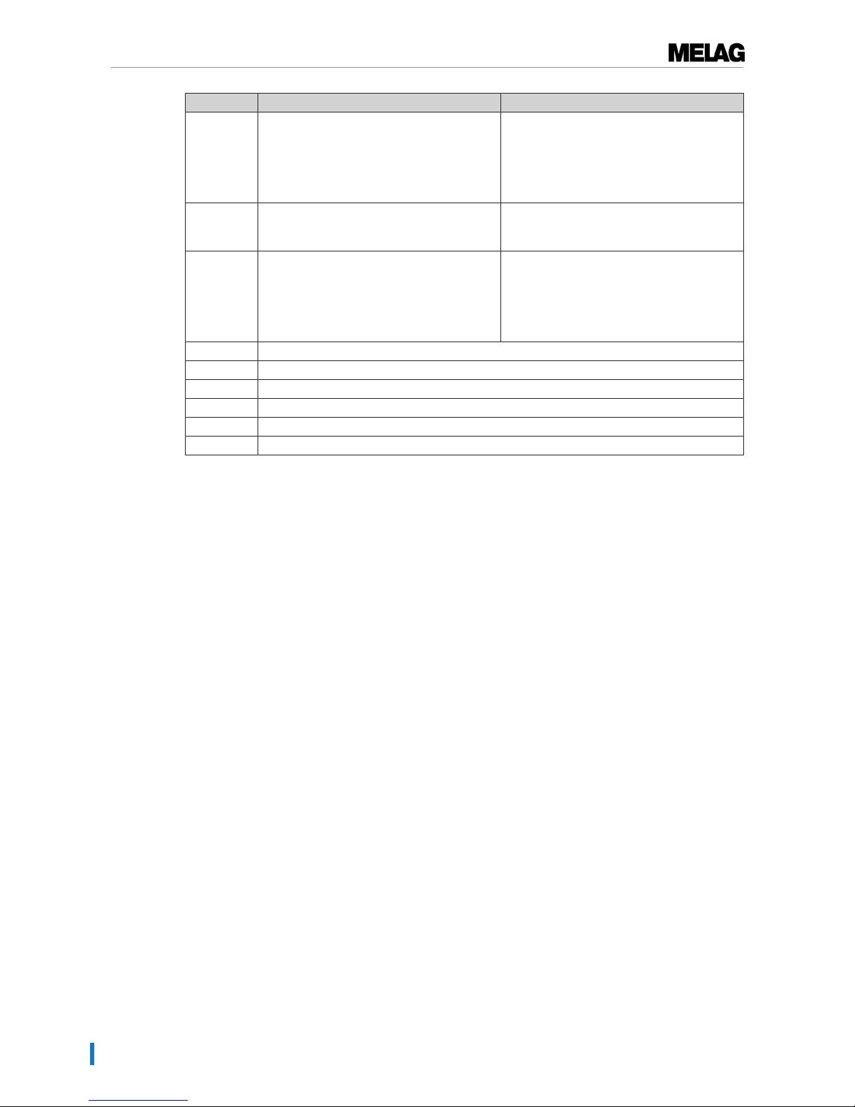
13 Malfunctions
76
Incident Possible causes What you can do
458 a) The date or time was set incorrectly.
b) The start time pre-selection timer has run
down but the steam sterilizer was switched
off at the time for which the start time was
selected.
a) Check the date and time settings and
correct if necessary (see Date & time [}page
53]).
b) Please note: The steam sterilizer must be
switched on at time for which the start time is
selected.
464 An attempt was made to perform actions on
the display, although the log printer is still
printing.
Please wait until the log printer has finished
printing the log(s). Then the desired action
can be performed.
465 a) The connection to the label printer has
been interrupted.
b) The label printer has not been switched
on.
a) Check whether the power cable is
connected to the socket and the Ethernet
cable of the label printer is correctly
connected with the steam sterilizer.
b) Switch on the label printer The Power LED
must illuminate green.
479 see event 397
486 see event 82
488 see event 457
489 see event 136
490 see event 136
492 see event 136
Page 77

14 Technical data
77
14 Technical data
Device type Vacuklav 41 B+ Evolution Vacuklav 43 B+ Evolution
Device dimensions (H x W x D) 56.5 x 47 x 57.5 cm 56.5 x 47 x 69 cm
Chamber diameter/depth Ø 25 cm | 35 cm Ø 25 cm | 45 cm
Chamber volume 18.4 litres 23.8 litres
Empty weight 60 kg 69 kg
Operating weight 81 kg 91 kg
Electricity supply 220-240 V, 50/60 Hz, 3400 W
Building fuses 16 A, FI protection 30 mA
Waste heat (with maximum
load)
1.7 kWh
Noise emission 64 dB(A)
Ambient temperature 5-40 °C (ideal range 16-26 °C)
Relative humidity max. 80% at 31 °C, decreases in a linear fashion up to max. 50%
relative humidity at 40 °C
Max. height 4000 m
Length of the power cable 2 m
Degree of protection (following
IEC 60529)
IP20
CE marking CE 0197, CE 0035
Feed water connection
Water quality DIN EN 13060, Appendix C
Min. flow pressure 1.5 bars at 3 l/min
Min. static water pressure 2 bar
Max. static water pressure 10 bar
Max. water consumption 0.74 L 0.83 L
Waste water connection
Max. through-flow volume 1.5 L 1.5 L
Max. water temperature 98 °C 98 °C
Page 78
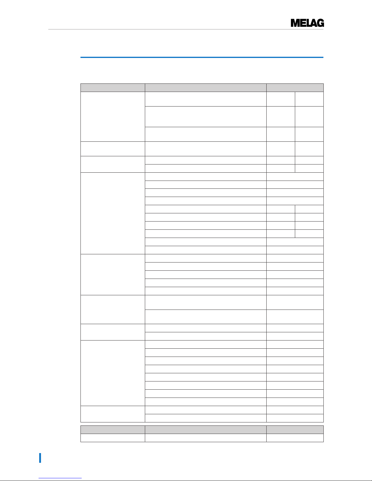
15 Accessories and spare parts
78
15 Accessories and spare parts
You can obtain the specified articles and an overview of further accessories from your stockist.
Category Article Order no.
Mounts Mount C "Plus"
for 6trays or 3 MELAstore-Boxes100
81370 81380
Mount D "Plus"
for 2MELAstore boxes200 or 2MELAstore
boxes100 and 2narrow trays
82640 82650
Mount E "Plus"
for 6 trays (standard) and 2 narrow trays.
82400 82700
Mount F "Plus"
for 3MELAstore-Boxes100 and 2 narrow trays
82660 82670
Trays Tray 00280 00230
Tray, narrow 01320 01310
Sterilization container with
a single-use paper filter in
accordance with DIN EN
868-8
15K (18 x 12 x 4.5 cm) 01151
15M (35 x 12 x 4.5 cm) 01152
15G (35 x 12 x 8 cm) 01153
17K (20 x 14 x 5 cm) 01171
17M, for 45 cm chamber depth (41 x 14 x 5 cm) --- 01172
17G, for 45 cm chamber depth (41 x 14 x 9 cm) --- 01173
23M, for 45 cm chamber depth (42 x 16 x 6 cm) --- 01231
23G, for 45 cm chamber depth (42 x 16 x 12 cm) --- 01232
28M (32 x 16 x 6 cm) 01284
28G (32 x 16 x 12 cm) 01285
MELAstore System MELAstore-Tray 50 (18 x 11.8 x 3 cm) 01180
MELAstore-Tray 100 (27.5 x 17.6 x 3 cm) 01181
MELAstore-Tray 200 (27.5 x 17.6 x 4.3 cm) 01182
MELAstore-Box 100 (31.2 x 19 x 4.6 cm) 01191
MELAstore-Box 200 (31.2 x 19 x 6.5 cm) 01192
Test body system MELAcontrol consisting of a Helix test body and
250 indicator strips
01080
MELAcontrol consisting of a Helix test body and 40
indicator strips
01075
Water treatment MELAdem 40 ion exchanger 01049
MELAdem 47 reverse osmosis unit 01047
For documentation: MELAflash CF card 01043
MELAflash card reader 01048
MELAprint 44 log printer 01144
Ethernet adapter for MELAprint 42/44 40295
MELAprint 60 label printer 01160
Network cable (cross-over), 2 m 15813
Network cable (cross-over), 5 m 15814
Network cable (cross-over), 10 m 15815
Other Water stop (leakage water detector) 01056
Surface-mounted siphon 37410
Category Article Order no.
Spare Parts Oil for door lock bushing 27515
Page 79

Glossary
79
Glossary
Air leakage
An air leakage is a location through which air can
pass in and out without this being desired. Verification of the leakage serves to prove that the volume
of air ingress in the chamber during the vacuum
phase does not exceed a value which would prevent steam penetration of the sterilizer load and
that the air leakage does not cause the possible
contamination of the sterilizer load during the drying phase.
AKI
Abbr.: working group instrument preparation
( "Arbeitskreis Instrumentenaufbereitung")
Authorized personnel
An authorized personnel can be medical stockists,
depot technicians or MELAG-authorized customer
services trained by MELAG.
Batch
Collection of sterilization material which has been
processed together in the same sterilization program.
BGV A1
BGV is the abbreviation for Berufsgenossenschaftliche Vorschriften (regulations from a professional
association). A1 stands for principles of prevention
Bowie & Dick test
Steam penetration test with a standard test package; described in DIN EN285; the test is recognized in the large-scale sterilization industry.
CF card
Abbr.: "Compact Flash Card"; a memory card for
digital data with a compact size. CF is a standard.
Condensate
Fluid (e.g. water) produced by the cooling of and
resultant separation from the vaporous state.
Conductivity
Conductivity is the opposite of electrical resistance;
measured in micro-Siemens/centimetre (µS/cm);
the greater the amount of dissolute matter in the
water, the better it can conduct electrical current
and thus the higher its conductivity.
Corrosion
The chemical alteration or destruction of metal materials by water and chemicals
Delay in boiling
This refers to the phenomenon that it is possible
under certain circumstances to heat a fluid beyond
its boiling point without them boiling. This represents an unstable state; even low-level agitation can
produce a large bubble within the shortest period,
which expands explosively.
Demineralized water
Water without the minerals usually found in normal
spring or tap water; is produced through ion exchange of normal tap water. It is used here as feed
water.
DGSV
Abbr.: Deutsche Gesellschaft für Sterilgutversorgung (German Society German Society for Sterile
Supply). The DSGV training centres are specified
in DIN 58946, part 6 as "Requirements of personnel".
DIN 58946-7
Standard – sterilization - steam steam sterilizers part 7: Building requirements and requirements
placed on the operating agents and the operation
of steam sterilizers in the health-care branch
DIN 58953
Standard – sterilization, sterile equipment supply
DIN EN 13060
Standard – small steam sterilizers
DIN EN 867-5
Standard – non-biological systems for use in sterilizers – part 5: The determination of indicator systems and test bodies for the performance inspection of type B and type S small sterilizers.
DIN EN ISO 11140-1
Standard – the sterilization of products for use in
medical treatment – chemical indicators – part 1:
General requirements
DIN EN ISO 11607-1
Standard - packaging for medical devices to be
sterilized in the final packaging - Part 1: Requirements placed on materials, sterile barrier systems
and packaging systems
Distilled water
From the Latin aqua destillata; also referred to as
aqua dest; water which to a great extent is free
from salts, organic material and micro-organisms,
is produced from normal tap water or pre-cleaned
water through the process of distillation (evaporation and subsequent condensation). It is used here
as feed water.
Double-jacket steam generator
Serves the quick generation of steam outside the
sterilization chamber, surrounds the sterilization
chamber
Page 80

Glossary
80
Dynamic pressure test of the sterilization chamber
Serves to prove that the rate of pressure variations
during a sterilization cycle does not exceed a particular value which could result in the damage of
the packaging material. [see also DIN EN 13060]
Empty chamber test
Test run without a load, performed to assess the
performance of a sterilizer without the influence of
a load; facilitating verification of the temperatures
maintained in comparison to the temperatures set.
[see also DIN EN 13060]
Evacuation
Creation of a vacuum in a vessel
Feed water
Feed water is required to produce steam for sterilization. Guide values for water quality in accordance with DINEN285 / DINEN13060 – Appendix
C
Fractionated vacuum procedure
A technical procedure in steam sterilization; the repeated evacuation of the sterilization chamber in
alternation with steam injection.
FTP
Abbr.: (File Transfer Protocol) is a data transmission procedure serving to transport data from the
internet. This data can include programs, files or
even information. Special FTP programs (FTP clients) serve to load the data onto a server.
Heat-up phase
The time required after the steam sterilizer has
been switched on / after the start of a sterilization
program, to heat the double-jacket steam generator before the sterilization procedure starts. The
duration is dependent on temperature at which
sterilization takes place.
Hollow body A
See product with narrow lumen
Hollow body article B
See simple hollow body
MELAG network adapter
Ethernet printer module for the MELAprint 42/44
log printer; a printer connection on one side and a
network connection on the other
Mixed loads
wrapped and unwrapped sterilization material
within a single load
Multiple wrapping
e.g. wrapped instruments sealed in a double layer
of film or wrapped in film and placed in an additional container or a container wrapped in textiles.
Network cable (crossover)
A crossover cable connects two computers
(through network cards) directly without the use of
a hub/switch. This type of connection corresponds
with the network connection of the steam sterilizer
in the practice network. The crossover cable does
not run in parallel between the connectors, rather
certain skinners are crossed.
Porous
Permeable for fluids and air e.g. textiles
Porous full load
Serves to prove that the values set on the control
satisfy the necessary sterilization conditions in porous loads with a maximum mass for which the sterilizer is designed in accordance with DIN EN
13060 [see also DIN EN 13060]
Porous partial load
Serves to prove that the values set on the control
allow steam to enter the pre-determined test package quickly and equally [see also DIN EN 13060]
Process evaluation system
Also known as the self-monitoring system – this
observes itself and compares the various sensors
during a current program.
Product with narrow lumen
An article open on one side to which the following
applies: 1 ≤ L/D ≤ 750 and L ≤ 1500 mm or an article with an opening on both sides which is: 2 ≤ L/D
≤ 1500 and L ≤ 3000 mm and which does not correspond to a hollow body article B; L…length of
hollow body article; D…Diameter of hollow body
article [see also DINEN13060]
RKI
Abbr.: "Robert-Koch-Institute". It is one of the most
important bodies for the safeguarding of public
health in Germany.
Simple hollow bodies
An article open on one side to which the following
applies: 1 ≤ L/D ≤ 5 and D ≥ 5 mm or an article
with an opening on both sides which is: 2 ≤ L/D ≤
10 and D ≥ 5; L…hollow body article length; D…
hollow body article diameter [see also DIN EN
13060]
Single wrapping
Wrapped once e.g. instruments sealed in foil – in
opposition to: Multiple wrapping
Soft sterilization packaging
e.g. a paper bag or transparent sterilization packaging.
Solid
Without hollows or gaps, solid, compact, closed
Page 81

Glossary
81
Solid load
Serves to prove that the necessary sterilization
conditions have been reached within the entire
load with the values set in the control. The load
must represent the largest weight of massive instruments designed for sterilization in a sterilizer in
accordance with DIN EN 13060. [see also DIN EN
13060]
Sterile barrier system
A closed minimum packaging which prevents the
entrance of micro-organisms e.g. through sealing
bags, sealed and re-usable containers and folded
sterilization towels etc.
Sterilization chamber
The interior of a sterilizer accommodates the sterilization material
Sterilization material
Unsterile, sterilizable material which is still to be
sterilized.
Sterilized equipment
Also referred to as a batch: a load which has
already been sterilized, i.e. is sterile
TCP
Abbr.: Transmission control protocol: refers to a
standard protocol for connecting computers and
networks.
Vacuum
In common parlance, an area devoid of all materialIn the technical sense: volumes with a reduced
gas pressure (at least air pressure)
VDE
Abbr. (German): "Verband der Elektrotechnik,
Elektronik und Informationstechnik e.V." (Alliance
of the Electronics, Electrotechnical and IT Industry).
Page 82

Your stockist
MELAG Medizintechnik oHG
Geneststraße 6-10
10829 Berlin
Germany
email: [email protected]
Web: www.melag.com
Responsible for content: MELAG Medizintechnik oHG
We reserve the right to technical alterations
BA_Evo_41B+_43B+_10081_10083_EN.pdf | Rev. 1 - 17/2091 | Modification date: 2018-03-14
 Loading...