

Page 1

User Manual
Sterilizer 205
Dry-heat sterilizer
EN
We thank you for your confidence demonstrated by the purchase of this MELAG product. As an owner-run and operated
family concern founded in 1951, we have a long history of successful specialization in hygiene products for practicebased use. Our focus on innovation, quality and the highest standards of operational reliability has established MELAG
as the world’s leading manufacturer in the instrument treatment and hygiene field.
You, our customer are justified in your demand for the best products, quality and reliability. Providing "competence in
hygiene" and "Quality – made in Germany", we guarantee that these demands will be met. Our certified quality
management systems is subject to close monitoring: Our certified quality management systems is subject to close
monitoring: one instrument to this end is our annual multi-day audit conducted in accordance with ISO13485 and
ISO9001. This guarantees that all MELAG products are manufactured and tested in accordance with strict quality
criteria.
The MELAG management and team.
Page 2

Page 3

Contents
Contents
Chapter 1 – General safety information ................................................................................................................................4
Chapter 2 – General Guidelines .............................................................................................................................................5
Formatting rules ...................................................................................................................................................................5
Symbols used.......................................................................................................................................................................5
Formatting rules ...................................................................................................................................................................6
Chapter 3 – Description of the device ...................................................................................................................................7
Scope of delivery..................................................................................................................................................................7
Intended use ........................................................................................................................................................................7
Views of the device ..............................................................................................................................................................8
Loading variations ................................................................................................................................................................9
Chapter 4 – Setup and Installation.......................................................................................................................................10
Requirements of the installation location ...........................................................................................................................10
Chapter 5 – First steps.......................................................................................................................................................... 11
Switching the hot air sterilizer on and off again..................................................................................................................11
Opening and closing the door ............................................................................................................................................12
Changing the mount...........................................................................................................................................................12
Chapter 6 – Sterilization .......................................................................................................................................................13
Preparing the sterilization material.....................................................................................................................................13
Heißluftsterilisator beladen.................................................................................................................................................13
Information regarding routine operation .............................................................................................................................14
Setting the temperature......................................................................................................................................................14
Selecting the sterilization times..........................................................................................................................................14
Removing the sterilized equipment ....................................................................................................................................14
Storing sterile instruments..................................................................................................................................................15
Chapter 7 – Function tests ...................................................................................................................................................16
Periodical checks ...............................................................................................................................................................16
Chapter 8 – Maintenance ......................................................................................................................................................17
Checks and cleaning..........................................................................................................................................................17
Chapter 9 – Malfunctions...................................................................................................................................................... 18
General events...................................................................................................................................................................18
Chapter 10 – Technical Data ................................................................................................................................................19
Chapter 11 – Accessories..................................................................................................................................................... 20
Glossary .................................................................................................................................................................................21
Page 4

Chapter 1 – General safety information
Chapter 1 – General safety information
When operating the device, comply with the following safety instructions as well as those
contained in subsequent chapters. Use the device only for the purpose named in these
instructions. Failure to comply with the set-up conditions can result in malfunctions or
damage to the device and/or human injury.
Power cable and power plug
n Only the power cable included in the scope of delivery may be connected to the device.
n The power cable may not be replaced by a cable determined to be insufficient.
Set-up installation and commissioning
n Only have the device set up, installed, and started up by people authorized by
MELAG.
n In accordance with current VDE specifications, the device is unsuitable for operation in explosive at-
mospheres.
n The device may only be repaired by the manufacturer or an agency which he has authorized to do so
(stockist or customer services).
n Check the device for any damage suffered during transport after unpacking.
n In the case of obvious or suspected damage/defects, the device may not be operated further. In such
cases, the device has to be repaired.
Danger of short circuit
n Liquids may not be permitted to reach the interior of the device. This could result in an electrical shock
or short circuiting.
Preparation and sterilization
n Do not place the objects to be sterilized on material produced from cellulose (e.g., paper, paper tow-
els, staple fiber, bandage material, etc.); this material would produce excessive heat accumulation
which would prevent the required heat equalization in the sterilizer.
n Observe the relevant standards and directives for the preparation of instruments.
Repair
n Never open the housing of the device. Incorrect opening and repair can compromise electrical safety
and pose a danger to the user. The guarantee and warranty are forfeited as soon as the device is
opened by anyone other than a member of a MELAG-authorized technical customer service.
4
Page 5

Chapter 2 – General Guidelines
Chapter 2 – General Guidelines
Please read this operating manual carefully before commissioning the product. The instructions include
important safety information. The functionality and value-retention of this device depend primarily on the
care accorded to it. Make sure to keep the Operating Manual near to the device. It represents a
component of the product.
Formatting rules
Example Explanation
see Chapter 2 Reference to another text section within this document
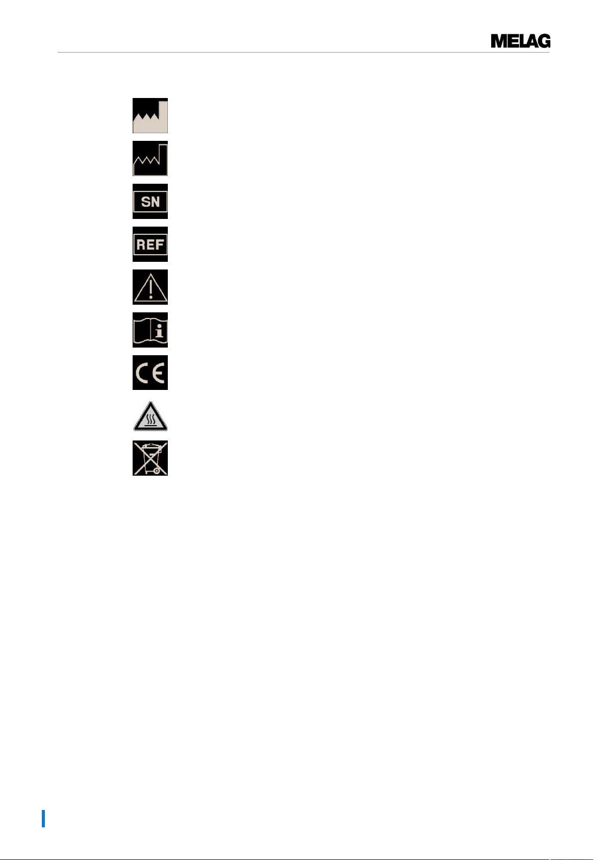
Symbols used
Symbol Explanation
Indicates a dangerous situation, which if not avoided, could entail slight to lifethreatening injuries.
Draws your attention to a situation, which if not avoided, could result in damage to the
instruments, the practice fittings or the device.
Draws your attention to important information.
5
Page 6
Chapter 2 – General Guidelines
Formatting rules
Manufacturer of the product
Date of manufacture of the product
Product serial number from the manufacturer
Article number of the product
The operating manual includes important safety information. Failure to comply with these
instructions can result in injury and material damage.
Please read this user manual carefully before commissioning the device.
In affixing the CE mark, the manufacturer declares that this product fulfils the basic
requirements of the EMC and low voltage directive.
Draws your attention to a hot surface. Should the fan fail, the cooling unit fins can
become hot.
The device may not be disposed as domestic waste. The vendor is responsible for
appropriate disposal of the device - it must be delivered to the vendor to be disposed of.
In affixing this symbol, the manufacturer furthermore declares that he has satisfied all the
legal requirements pertaining to the release, redemption and environmentally sound
disposal of electric and electronic appliances.
MELAG devices are synonymous with long-term quality. When you eventually need to
decommission your MELAG device, we offer a special disposal service. Simply contact
your stockist.
6
Page 7

Chapter 3 – Description of the device
Chapter 3 – Description of the device
Scope of delivery
Please check scope of delivery before connecting the device.
Standard scope of delivery
▪ 1x Sterilizer 205
▪ 1x User manual
▪ 1x Declaration of conformity
▪ 1x Warranty certificate
▪ 1x Power cable
▪ 1x Mount 1 or mount 2 (depending on the order)
Optionally
▪ Tray
▪ Tray jack
▪ Standard tray jack
▪ Standard tray cassette (unperforated)
Intended use
This hot air sterilizer is intended for use in the cosmetics sector, the cosmetic chiropody and the veterinary
sector. It was designed for the sterilization of objects made of non-flammable (inorganic) materials with a
minimum temperature resistance of 220°C (e.g. metal, glass, porcelain, stone or enamel). Comply with
the restricting information from the instrument manufacturer. Porous sterilization material is unsuitable for
hot air sterilization.
7
Page 8

Chapter 3 – Description of the device
2
1
3
4
5
6
7
8
11
9
10
13
12
Views of the device
Fig.1: Fore device view
1 Device foot
2 Temperature controller
3 Indicator lamp heating
4 Thermometer
5 Indicator lamp network
6 On/Off switch and time setting
7 Door handle
8 Door (opens forwards)
9 Fan
10 Type plate
11 Connection for the power supply
and the device fuse
Fig.2: Rear view of the device
12 Mounting
13 Sterilization chamber
Fig.3: View of the interior
8
Page 9

Chapter 3 – Description of the device
Loading variations
The hot air sterilizer is delivered with a mount for the acceptance of trays or standard tray cassettes. If one
or two trays are ordered with the device, the scope of delivery will include a tray jack.
The loading versions with devices with trays and standard tray cassettes are possible in the following
sizes:
▪ Tray (WxHxD): 19x2x36 cm
▪ Standard tray cassette (WxHxD): 19x4x29 cm
Mounting 1
Mount 1 can hold up to six trays.
Mounting 2
Mount 2 can hold three standard tray cassettes or three trays.
Both mounts are easy to replace. Comply with the instructions under point Changing the mount [}page
12] in chapter First steps [}page 11].
9
Page 10

Chapter 4 – Setup and Installation
Chapter 4 – Setup and Installation
Requirements of the installation location
NOTICE
The mains plug and the fuse must be easily accessible.
n Set up the device in such a fashion that the power plug can be disconnected from the mains
quickly following danger and that the fuse is easy to access.
Please observe and comply with the following instructions relating to the set-up.
u Install the device in a dry and dust-protected location.
u Install the device with a minimum clearance of 10 cm to other devices and walls, especially flammable
parts.
u Ensure sufficient ventilation. Ensure sufficient clearance to the top for free removal of the warm air.
The device may not be used as an installation device and not be used in the immediate treatment
area.
u The installation surface must be level and able to support the weight of the unit.
Tests after set-up
Perform a temperature check after setting-up the device using thermo sensors or bio indicators. Place the
test equipment in the area of the sterilization chamber in which the sterilization temperature is reached the
most slowly. This also depends on the arrangement and nature of the sterilization material.
10
Page 11

Chapter 5 – First steps
Chapter 5 – First steps
Switching the hot air sterilizer on and off again.
The hot air sterilizer is activated via the time switch (On/Off switch) and switches itself off after a pre-set
time. The fan comes to standstill after c. 45 seconds.
PLEASE NOTICE
Disconnect the mains plug if the device has not been operated for a long period of time.
Setting the operating time:
u Set the On/Off switch to the required operating time (turn clockwise).
ÊThe control lights network and heating will remain illuminated until the time expires.
ÊThe hot air sterilizer can be set to continuous operation. In this case, the hot air sterilizer must be
switched off manually.
Activating and deactivating continuous operation:
u Switch the On/Off switch to the "I" position (turn anti-clockwise).
ÊThe control lamp will remain illuminated; the control lamp for the heating will switch on and off. The
set temperature will be kept constant by the heating switching on and off.
u Switch the On/Off switch to the "0" position to switch off continuous operation.
ÊThe control lamps network and heating will extinguish.
11
Page 12

Chapter 5 – First steps
Opening and closing the door
ü
The device must always be deactivated before it is opened. Do not open the door or add any objects
after the sterilization procedure has started; this could result in cooling and the object not being sterilized for a sufficient time.
1. Move the On/Off switch to the "0" position to switch off.
2. Open the door forwards to open.
3. Move the door forwards to open.
Changing the mount
The mounts are installed to the left and the right in the sterilization chamber and can be replaced as
follows:
1. Slide the mount upwards from below and pull off to the side.
2. Set the mount with the screws into the larger aperture and press the mount downwards.
CAUTION
Danger of burns from hot metal surfaces
n Allow the device to cool sufficiently before opening.
n Do not touch any hot metal parts.
12
Page 13

Chapter 6 – Sterilization
Chapter 6 – Sterilization
Preparing the sterilization material
Cleaning and disinfection must always have been performed before sterilization. Only in this way is it
possible to guarantee the subsequent sterilization of the Sterilization material. The materials used, the
cleaning fluid and treatment procedures used are of decisive significance.
Please observe the following information before loading:
u Clean, disinfect and dry the instruments before every sterilization.
u Comply with the specifications of the manufacturer’s cleaning and care information when treating the
sterilization material. Only so is it possible to guarantee correct cleaning and disinfection and subsequent sterilization.
u Never place the sterilization material together in blocks, as this will prevent heat equalization.
u Do not place the sterilization material on cellulose, as this can result in a heat build-up.
u Always pack the sterilization material in aluminium containers. Stainless steel is unsuitable due to its
reduced heat conductivity. Do not use any textiles, paper or polyamide film as packaging. This packaging is unsuitable for high sterilization temperatures.
Heißluftsterilisator beladen
Only when correctly loaded is effective sterilization and good drying possible. Ensure the following during
loading:
u Insert trays or standard tray cassettes in the chamber only with their appropriate mount.
u When loading, ensure that air can circulate around the instruments unhindered. Do not load the trays
or standard tray cassettes one-sided and do not stack the sterilized equipment.
Example of a correct load
Tray
Standard tray cassette Standard tray cassette
Example of an incorrect load
Tray
13
Page 14

Chapter 6 – Sterilization
Information regarding routine operation
The sterilization temperature before every sterilization procedure must amount to 180 °C. To this end, the
setting of the sterilization time must take into account the Equilibration time. The pure aborticide time
amounts to 30 minutes at 180 °C.
1. Wait 15 minutes after the thermometer has reached 180 °C.
2. Set the required sterilization time. Comply with the specifications under Selecting the sterilization
times [}page 14] .
3. Check the ventilator noise: ensure that the mechanical air movement is functioning correctly.
Setting the temperature
Set the temperature for the hot air sterilizer as follows:
1. Turn the temperature control to 180 °C.
2. Wait until the thermometer reaches 180°C and allow the device to heat up for 15 minutes.
Ê During this time, the hot air sterilizer heats up the complete sterilization chamber.
3. Set the sterilization time via the “On/Off switch”. Comply with the information of the sterilization times
table.
Selecting the sterilization times
Do not exceed the specified loading quantities. Use only trays and cartridges made of aluminium. When
needing to pack with foil, use aluminium foil.
Table1: Load type and operating time
load Packaging Pre-heating time Operating time
max. of 1 kg, including 2 trays unwrapped 15 min 60 min
max. of 4 kg, including 6 trays unwrapped 15 min 75 min
max. 1 kg inc. 1 standard tray cassette wrapped 15 min 75 min
max. 4 kg inc. 3 standard tray cassettes wrapped 15 min 120 min
Removing the sterilized equipment
CAUTION
Danger of burns from hot metal surfaces
n Allow the device to cool sufficiently before opening.
n Do not touch any hot metal parts.
CAUTION
Unsterile instruments resulting from damaged packaging. This endangers the health of
the patient and the practice team.
n Should the packaging be damaged, re-pack the sterilization material and re-sterilize it.
14
Comply with the following when removing the sterilized equipment:
u Use a tray jack to remove the tray.
u Never touch the sterilized equipment, the device interior or the inside of the the door with unprotected
hands. The components are hot.
Page 15

Chapter 6 – Sterilization
Storing sterile instruments
The maximum storage time is dependent on the packaging and the storage conditions. For standardconform packaged Sterilized equipment – (if protected from dust) it can amount to up to six months.
Comply with the provisions of DIN 58953, part 8 and the criteria specified below for the storage of
sterilized equipment:
u The possible length of storage depends on the type of packaging
u Do not store the Sterilized equipment in the treatment room
u Protected against dust e.g. in a closed instrument cupboard
u Protected from damage to their shiny surfaces
u Protected from significant temperature differences
u Protected from moisture (e.g. from alcohol, disinfection fluids)
15
Page 16

Chapter 7 – Function tests
Chapter 7 – Function tests
Periodical checks
We recommend an annual inspection using bio-indicators, thermocouples or maximum thermometers.
▪ Comply with the valid regional legal specifications.
▪ When performing the spore test using biological indicators, the spore packets are to be clamped under
an instrument in order to prevent the package from being sucked into the fan motor.
16
Page 17

Chapter 8 – Maintenance
Chapter 8 – Maintenance
Checks and cleaning
Check the chamber, including the door seal and chamber sealing face and the mount once a week for
impurities, deposits or damage. If you find any impurities, remove the standard tray cassettes or cartridges
and the mount from the chamber. Clean the soiled components. When cleaning the chamber, the mount
for the load, chamber seal face and the door seal, please comply with the following:
▪ Switch off the steam sterilizer before cleaning and remove the power plug from the socket.
▪ Ensure that the chamber is not hot.
▪ Use a soft, non-fuzzing cloth.
▪ Use a chlorine- and vinegar-free cleaning fluid.
▪ First soak the cloth with the cleaning alcohol or spirit and attempt to remove the impurities with this
method.
▪ Only if the chamber, mount or chamber seal face has persistent soiling should you use a mild stainless
steel cleaning agent, with a pH value between 5 and 8.
▪ To clean the door seal, use a neutral liquid cleaning agent.
▪ You should not allow cleaning fluid to enter the piping coming from the chamber.
▪ Do not use any hard objects such as metal saucepan cleaner or a steel brush.
▪ Check the door seal for damage on a daily basis. Replace the door seal if necessary.
▪ Check the contact pressure of the door The entire surface of the door must be in contact with the frame.
NOTICE
Inappropriately performed cleaning can lead to the scratching of and damage of surfaces
and the development of leaks in sealing surfaces. This creates conditions favourble to
dirt deposits and corrosion in the sterilization chamber.
Comply with all information regarding cleaning of the part affected.
17
Page 18

Chapter 9 – Malfunctions
Chapter 9 – Malfunctions
General events
Incident Possible cause What you can do
The temperature display of
the thermometer deviates
by more than 8 °C than set
on the controller.
The device does not switch
off. The indicator lamp
“network” and “heating”
illuminate.
The temperature displayed
deviates from the set
temperature. The
thermometer displays less
than 180°C or falls from
180°C to c. 150°C within c.
5 min. and continues to fall.
Under circumstances, there
is no audible ventilator
noise.
The device is too hot (over
180°C).
The temperature fluctuates
between 210-240°C. The
indicator lamp network is
illuminated. The indicator
lamp heating is
continuously off or on/off
every 20 seconds.
The control button has
been maladjusted.
The timer is defective or
is set to continuous
operation.
The temperature has
been set too low.
The temperature
controller rotary knob was
unintentionally turned or
mal-adjusted during
unpacking or incorrect
handling e.g. during
cleaning.
The “Temperature
controller” has been set
incorrectly or is defective.
Increase or reduce the temperature by turning
the temperature controller:
Higher temperature: Anti-clockwise
Lower temperature: Clockwise
Check that the "On/Off switch" is set to "I" or "0".
If the timer is defective, inform an authorized
customer services.
The device can be operated provisionally on a
semi-automatic basis by actuating the "On/Off
switch" manually.
Set a higher temperature.
The temperature controller must be readjusted
by a service technician. Inform an authorized
customer services.
Provisionally, turn the temperature controller so
that the desired temperature is displayed on the
device thermometer.
Set the temperature controller to e.g. 180°C
and check whether this temperature has been
reached / is displayed on the thermometer (note
the heating and equilibration time).
Should values deviate, the rotary knob must be
readjusted. Task an authorized customer
services.
If the thermostat is defective, inform an
authorized customer services.
Provisionally, turn the "temperature control"
rotary knob so that the desired temperature is
displayed on the device thermometer.
18
Page 19

Chapter 10 – Technical Data
Chapter 10 – Technical Data
Device type Sterilizer 205
Electrical power 1100 W
Electrical connection 220-240V 50/60 Hz
Device fuse 2 x 6.3 A T
Noise emission 49 dB
Waste heat 1.3 MJ
Weight 17 kg
Please observe the maximum load: 5.5 kg including 6 trays
Maximum mains voltage supply variations: +/- 10 %
Maximum voltage range 207 - 253 V
Relative humidity up to 31°C max. 80% | up to 40°C max. 50%
Degree of protection IP 20
Protection category I
Sterilization chamber (WxHxD)
Dimensions (WxHxD) 31 x 47 x 38.5 cm
Ambient temperature 5°C - 40°C
Volume of the sterilization chamber 14 litres
1
19x 20 x 36 cm
1
with installed mounts
19
Page 20

Chapter 11 – Accessories
Chapter 11 – Accessories
Table2: Accessories
Designation of article Order.-No.
Mounting 1 60030
Mounting 2 60040
Tray 02000
Standard tray cassette 00287
Tray jack 28890
Jack for standard tray cassette 28895
20
Page 21

Glossary
DIN 58953
Standard – sterilization, sterile equipment supply
Equilibration time:
The equilibration time comprises the time required
to to heat all the locations of the device and the
sterilization material to the required temperature of
180 °C.
Sterilization material
Unsterile, sterilizabe material which is still to be
sterilized.
Sterilized equipment
Also referred to as a batch: a load which has
already been sterilized, i.e. is sterile
VDE
German abbreviation "Verband der Elektrotechnik,
Elektronik und Informationstechnik e.V." (Alliance
of the Electronics, Electrotechnical and IT Industry).
Glossary
21
Page 22

MELAG Medizintechnik oHG
Geneststraße 6-10
10829 Berlin
Germany
E-Mail: info@melag.com
Web: www.melag.com
Responsible for content: MELAG Medizintechnik oHG
We reserve the right to technical alterations
Your stockist
BA_Heißluftsterilisator 205_EN.pdf | Rev. 5 - 16/1198 | Modification date: 13.06.2016
 Loading...