

MeiTrack MVT400 User Manual

MVT400 USER MANUAL
Page 1 of 27
GPS
Vehicle
Tracker
User Manual
V1.52
MVT400

MVT400 USER MANUAL
Page 2 of 27
Contents
1. Product Overview....................................................................................................................3
2. For Your Safety.......................................................................................................................3
3. MVT400 Characteristics ...........................................................................................................4
4. Getting Started ......................................................................................................................5
4.1 Hardware and Accessories ................................................................................................5
4.2 View..............................................................................................................................5
4.3 Functional Parts...............................................................................................................5
4.4 Connecting and Installation...............................................................................................7
5. Change Password....................................................................................................................7
6. Time Zone.............................................................................................................................8
7. Track .................................................................................................................................... 8
7.1 Track by SMS..................................................................................................................8
7.2 Track by Calling...............................................................................................................9
7.3 Track by Preset Interval....................................................................................................9
7.4 Google Earth and Google Map............................................................................................9
7.5 Track by 800E...............................................................................................................10
7.6 Track by GPRS (Our Protocol) between Server and Tracker................................................... 10
7.6.1 Configure MVT400 by Parameter Editor V1.39............................................................ 10
7.6.2 Configure MVT400 by SMS...................................................................................... 10
7.6.3 Add MVT400 to 800D web based tracking software.....................................................12
8. Authorization .......................................................................................................................14
9. Application Examples for Inputs..............................................................................................14
9.1 SOS Button Connection .................................................................................................. 14
9.2 Ignition Detection..........................................................................................................15
9.3 Analog Input (AD1, AD2……AD8)...................................................................................... 15
10. Low Battery Alarm ..............................................................................................................15
11. Speeding Alarm..................................................................................................................15
12. Movement/Geo-fence ..........................................................................................................16
12.1 Movement Alarm .........................................................................................................16
12.2 Geo-fence Alarm.......................................................................................................... 16
13. Output Control.................................................................................................................... 17
13.1 Output Control (Immediate) .......................................................................................... 17
13.2 Output Control (Conditional).......................................................................................... 17
13.3 Application Examples for Outputs................................................................................... 17
13.3.1 Internal Relay (Output1) ....................................................................................... 17
13.3.2 External Relay (Output2) ......................................................................................18
14. Heading Change Report ....................................................................................................... 18
15. Heartbeat .......................................................................................................................... 19
16. Power Down....................................................................................................................... 19
17. GPS Antenna Disconnection Alarm......................................................................................... 19
18. Initialization....................................................................................................................... 19
19. Password Initialization ......................................................................................................... 20
20. Copyright and Disclaimer ..................................................................................................... 20
Annex 1. SMS Command List .....................................................................................................20
Annex 2. Troubleshooting ..........................................................................................................26
Contacts .................................................................................................................................27
MVT400 USER MANUAL
Page 3 of 27
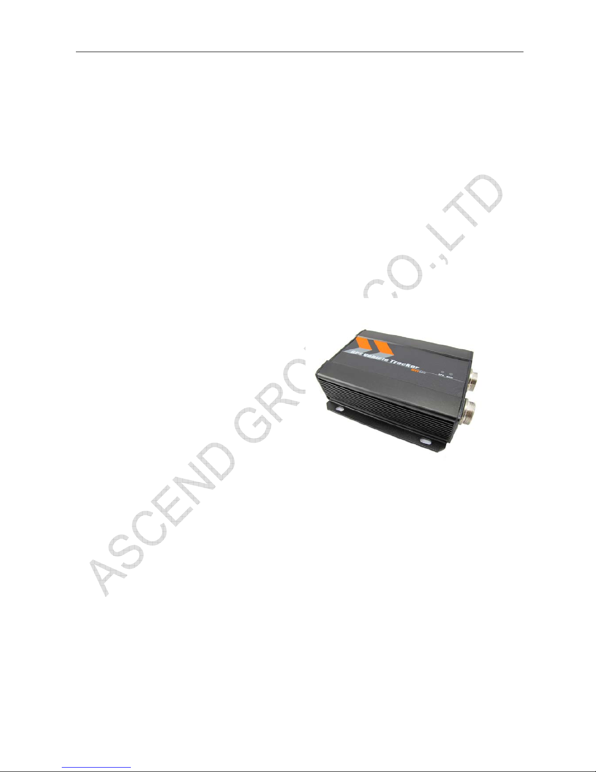
1. Product Overview
MVT400 is a GPS/GPRS based tracking device designed for heavy machinery equipment, construction
machines and vehicles.
MVT400 has inbuilt GPS module to obtain accurate position data and utilizes its GSM capability to send the
position data to a specified mobile phone or server base for tracking and management.
MVT400 is waterproof (IP66) and has 2 digital inputs, 7 analog inputs, 1 open circuit output and 1 relay
output for different reports and applications.
MVT400 has the following functions and features:
 SMS and GPRS TCP/UDP Communication
 Track on Demand
 Show Location Directly on Mobile Phone
 Track by Time Interval
 Inbuilt Motion Sensor for Power Saving
 Inbuilt Backup Battery
 SOS Panic Button
 Movement Alarm
 Geo-fencing Control
 Low battery Alarm
 Speeding Alarm
 GPS Blind Area Alarm (in/out)
 GPS Antenna Disconnection Alarm
 Power-cut Alarm
 Voltage Detection for External Power
 Engine Cut (Stop Engine)
 2 Digital Inputs (1 negative and 1 positive triggering)
 7 Analog Inputs
 1 OC Outputs
 1 Relay Output
 1 RS232 Output (Optional)
 Waterproof (IP66)
2. For Your Safety
Read these simple guidelines. Not following them may be dangerous or illegal.
Proper Connection When connecting with other device, read carefully its manual so as to
carry out correct installation. Do not connect it to other incompatible
devices.

MVT400 USER MANUAL
Page 4 of 27
Qualified Accessories Use original parts, qualified batteries and peripheral equipments to
avoid damage to MVT400.
Safe Driving Drivers should not operate this product while driving.
Qualified Service Only qualified personnel can install or repair MVT400.
Confidential Phone Number For safety reason, do not tell other people the mobile phone number of
your MVT400 without taking precautions of security settings.
3. MVT400 Characteristics
Items Specification
Power Supply +9V - +36V/1.5A (without internal relay)
+16V-+36V/1.5A (with internal relay)
Backup Battery 850mAh
Normal power consumption 85mA/h
Dimension 123*83*37mm
Installation Dimension 123*103*37mm
Weight 350g
Operating temperature -20° to 55° C
Humidity 5% to 95% Non-condensing
Frequency GSM 900/1800/1900Mhz or GSM 850/900/1800/1900Mhz
GPS Module latest GPS SIRF-Star III chipset
GPS Sensitivity -159dB
GPS Frequency L1, 1575.42 MHz
C/A Code 1.023 MHz chip rate
Channels 20 channel all-in-view tracking
Position Accuracy 10 meters, 2D RMS
Velocity Accuracy 0.1 m/s
Time Accuracy 1 us synchronized to GPS time
Default datum WGS-84
Reacquisition 0.1 sec., average
Hot start 1 sec., average
Warm start 38 sec., average
Cold start 42 sec., average
Altitude Limit 18,000 meters (60,000 feet) max.
Velocity Limit 515 meters/second (1000 knots) max.
LED 2 LED lights to show GPS/GSM status.
Button One SOS Button(share with Digital Input1)
Interface 2 digital inputs (1 negative and 1 positive triggering);
7 analog inputs;
1 OC output;
1 Relay output;
1 RS232 output (Optional).

MVT400 USER MANUAL
Page 5 of 27
4. Getting Started
This section will describe how to set up your MVT400.
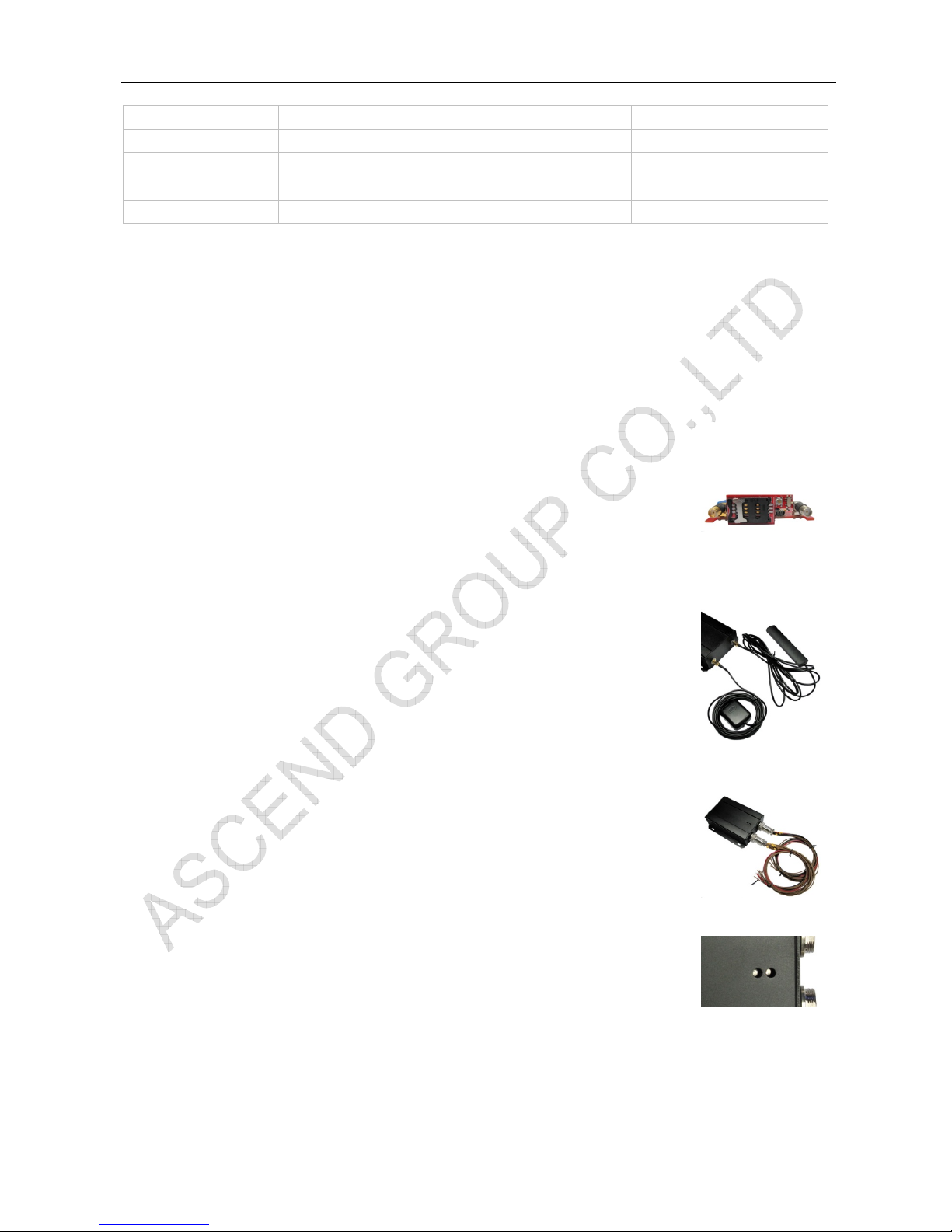
4.1 Hardware and Accessories
MVT400 is supplied in a box which includes:
MVT400 with
Battery
GPS Antenna GSM Antenna Socket cables CD
4.2 View
Front View Side View Back View
4.3 Functional Parts
GPS LED (Blue)
On One button is being pressed or input is active
Flashing ( every 0.1 second) The unit is being initialized
Flashing (0.1 second on and 2.9 seconds off) The unit has a GPS fix
Flashing (1 second on and 2 seconds off) The unit has no GPS no fix
GSM LED (Green)
On One call is coming in / one call is being made
Flashing ( every 0.1 second) The unit is being initialized
Flashing (0.1 second on and 2.9 seconds off) The unit is connected to the GSM network
Flashing (1 second on and 2 seconds off) The unit is not connected to the GSM network

MVT400 USER MANUAL
Page 6 of 27
Power On/Off Switch(Inside) Open or Close Unit.
SOS Button SOS button is connected with the wires. Press it to send SOS alarm to
the preauthorized phone number.
Mini USB(Inside) Used for firmware update, configuration on PC. (USB-to-Serial Adaptor
is required for firmware update, configuration )
SIM Card Holder To insert SIM card here
GSM Antenna Connector for GSM antenna (SMA Connector)
GPS Antenna Connector for GPS antenna (SMA Connector)
Screw Holes There are 4 screw holes on the tracker, 2 along either side that act a s
fixing points to the vehicle
PINs Connector
PIN Color Function
12-1 Brown Digital Input 1. Negative triggering.
12-2 Brown Digital Input 2. Positive triggering.
12-3 Brown AD2. 12 Bits Resolution Analog Inputs. Input voltage: 0~50V.
12-4 Brown AD3. 12 Bits Resolution Analog Inputs. Input voltage: 0~50V.
12-5 Brown AD4. 12 Bits Resolution Analog Inputs. Input voltage: 0~50V.
12-6 Brown AD5. 12 Bits Resolution Analog Inputs. Input voltage: 0~50V.
12-7 Brown AD6. 12 Bits Resolution Analog Inputs. Input voltage: 0~50V.
12-8 Brown AD7. 12 Bits Resolution Analog Inputs. Input voltage: 0~50V.
12-9 Brown AD8. 12 Bits Resolution Analog Inputs. Input voltage: 0~50V.
12-10 Black Ground
12-11 Red DC In (power input).
No Use Inside Relay Input Voltage: +9V~+36V/1.5A. 12V suggested.
Use Inside Relay Input Voltage: +16V~+36V/1.5A. 24V suggested.
10-4 Brown Relay Output COM(250VAC/3A)
10-5 Brown Relay Output NC(250VAC/3A)
10-6 Brown Relay Output NO(250VAC/3A)
10-7 Brown OC Output
Low voltage (0V) when effective and open circuit when ineffective.
Output open Circuit sink voltage (ineffective): 45V max.
Output low voltage sink current (effective): 500mA max.
10-8 Black Ground
10-9 Black Ground
10-10 Red Same As 12-11
DC In (power input).
No Use Inside Relay Input Voltage: +9V~+36V/1.5A. 12V suggested.
Use Inside Relay Input Voltage: +16V~+36V/1.5A. 24V suggested.
DC Characteristics of PINs
PIN Inactive Active Maximum
DC IN / +9V~+36V/1.5A
or +16V~+36V/1.5A
45V
AD 2/3/4/5/6/7/8 / 0-50V 50V
MVT400 USER MANUAL
Page 7 of 27
Input 1(Normal Is SOS ) OD/OC or >1V 0V(GND) 45V
Input 2 OD/OC or 0V(GND) >3V 45V
OC Output Open Circuit 0V (GND) 45V/500mA
Relay Output NC connect to COM NO connect to COM 250VAC/3A
RS232 Interface / / -12V~+12V
4.4 Connecting and Installation
Read this manual before using your MVT400 and check if all parts are included in the packaging box.
4.4.1 Ensure that your MVT400 has a working SIM installed.
- Check that the SIM has not run out of credit (test the SIM in a phone to make sure it can send and
receive SMS)
- Check that the SIM Lock code is turned off
- If you require the function of sending an SMS location report to the authorized phone number when it
makes a call to the MVT400, please make sure the SIM installed supports displaying caller ID.
Before inserting SIM card, cut off the power for MVT400.
Install SIM Card
- Unscrew and remove the front cover of MVT400.
- Insert the SIM card by sliding it into the card slot with the chip module facing to the
connectors on PCB.
- Put back the front cover and screw it up.
4.4.2 Antenna Connection
Connect the GSM Antenna to MVT400.
Connect the GPS Antenna to MVT400.
- GPS antenna is used to receive satellite signals in the sky. It sho uld be fixed to face
the sky (to be placed under the windscreen is recommended) and should not be
covered or shielded by any objects containing metal.
4.4.3 Find a suitable place inside the car for installing MVT400. Wiring connections
must be firm and reliable and the joints should be wrapped with insulating tape
tightly. The unused electrical wire should be properly insulated.
Check if all wirings have been connected correctly and then connect the AVL unit to
the motor power.
Check that the Red LED (Battery) is flashing 1 second on and 2 seconds off.
Make a missed phone call the MVT400 using a mobile phone to check if the calling can
go through and the MVT400 replies with an SMS indicating longitude, latitude, speed
and date.
5. Change Password
Command: W******,001,######

MVT400 USER MANUAL
Page 8 of 27
Description: Change user’s password.
Note:
1. ****** is user’s password and the default password is 000000. The tracker will only accept commands
from a user with the correct password. Commands with wrong password will be ignored.
2. ###### is the new password. Password should be 6 digits.
Example:
W000000,001,123456
W123456,001,999999
6. Time Zone
Command: W******,032,T
Description: Correct time into your local time
Note:
1. Default time of the tracker is GMT
2. This correction is applied to location reports by SMS and SMS alarms.
T=0, to turn off this function.
T=[1, 65535] to set time difference in minute to GMT.
For those ahead of GMT, just input the time difference in minute directly. For example, GMT+8,
W000000,032,480
‘-‘is required for those behind GMT. For example, W000000,032,-120.
Example:
W000000,032,480
W000000,032,-120
7. Track
7.1 Track by SMS
- Track on Demand - Reply with longitude, latitude, speed and date
Command: W******,000
Description: Get the current location of the tracker, send this SMS or make a telephone call directly to the
tracker and it will report its longitude and latitude by SMS with format as follows:Latitude = 22 32 36.63N Longitude = 114 04 57.37E, Speed = 2.6854Km/h, 2008-12-24,01:5 0
Example:
W000000,000
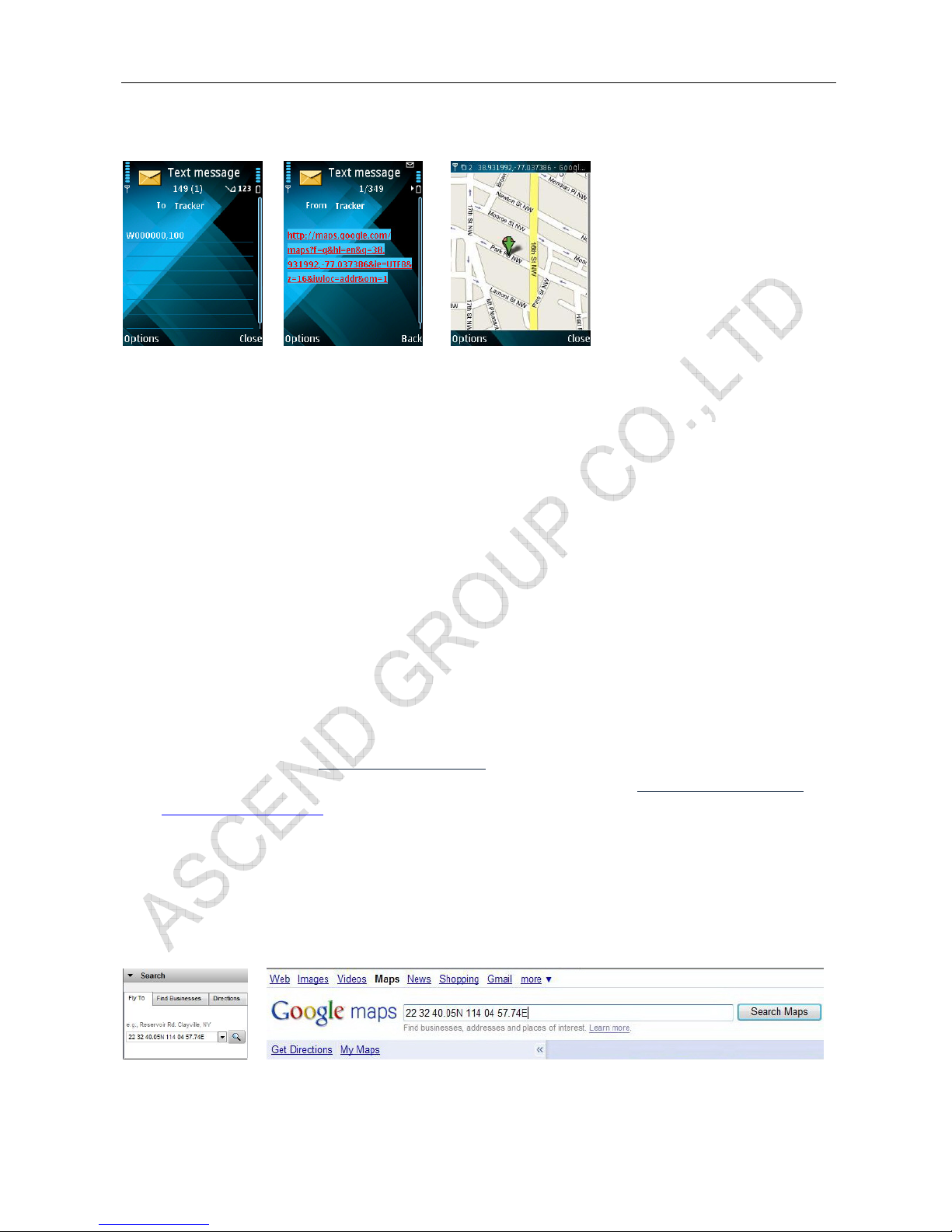
- Track on Demand - Reply with a Google link
Command: W******,100
Description: Send this command to the tracker and then you receive an SMS with an http link. Click on the
link then the location can be shown directly on Google Map on your mobile phone. For example:
http://maps.google.com/maps?f=q&hl=en&q=22.543908,114.088564&ie=UTF8&z=16&iwloc=addr&om=1
Note: Only smart phones and PDA support this function.
MVT400 USER MANUAL
Page 9 of 27
Example:
W000000,100
7.2 Track by Calling
Make a missed call to the tracker and it will report it s longitude and latit ude by SMS with form at as follows:Latitude = 22 32 36.63N Longitude = 114 04 57.37E, Speed = 2.6854Km/h, 2008-12-24,01:5 0
7.3 Track by Preset Interval
Command: W******,002,XXX
Description: Set an interval for the tracker to continuously return its location by SMS
Note:
1. XXX is the interval in minute.
2. If XXX=000 to turn off tracking by time
Example:
W000000,002,030
The tracker will send location data back to your mobile phone every 30 minutes.
7.4 Google Earth and Google Map
Download Google Earth from http://earth.google.com/
.
Start Google Earth (For more information about Google Earth please refer to http://earth.google.com/
) or
go to http://maps.google.com
in your Internet Explorer.
Input the latitude and longitude that you receive from the tracker by SMS and click the search button.
Google Earth or Google Maps will display the location for you.
Example:
When you receive: Latitude = 22 32 40.05N Longitude = 114 04 57.74E
Type as the following picture shows:
(Note: you should input the latitude and longitude as: 22 32 40.05N 114 04 57.74E)
And then you can find the location of your tracker:
 Loading...