

MCZ Forma Wood 65, Forma Wood 75, Forma Wood 115, Forma Wood 95, Forma Wood B95 Installation Manual
8901155100
USE AND INSTALLATION MANUAL
EN

INSTALLATION AND USE MANUAL
Contents
page 2
Contents
Technical service – MCZ S.p.A. all rights reserved - Reproduction prohibited
INTRODUCTION .................................................................................................................................... 4
1. WARNINGS AND WARRANTY CONDITIONS ...................................................................................... 5
1.1. SAFETY WARNINGS ................................................................................................................................ 5
1.2. OPERATING WARNINGS .......................................................................................................................... 5
1.3. WARRANTY CONDITIONS ........................................................................................................................ 6
1.3.1. Restrictions ................................................................................................................................ 6
1.3.2. Exclusions .................................................................................................................................. 6
1.4. IMPORTANT INFORMATION FOR CORRECT DISPOSAL OF THE PRODUCT IN ACCORDANCE WITH EC
DIRECTIVE 2002/96/EC .................................................................................................................................. 6
2. INSTALLATION IN ACCORDANCE WITH UNI 10683 .......................................................................... 7
2.1. OPERATING AREA ................................................................................................................................... 7
2.2. PRECAUTIONS ........................................................................................................................................ 7
2.3. CONNECTION TO THE EXTERNAL AIR INTAKE .......................................................................................... 8
2.4. CONNECTION TO THE FLUE PIPE ............................................................................................................ 9
2.5. FLUE PIPE .............................................................................................................................................. 9
2.5.1. Examples of flue pipes .............................................................................................................. 10
2.6. COWL .................................................................................................................................................. 11
3. DIMENSIONS AND TECHNICAL SPECIFICATIONS ........................................................................... 12
3.1. Dimensions of the Forma Wood 65 ......................................................................................................... 12
3.2. Dimensions of the Forma Wood 75 ......................................................................................................... 13
3.3. Dimensions of the Forma Wood 95 ......................................................................................................... 14
3.4. Dimensions of the Forma Wood B95 ....................................................................................................... 15
3.5. Dimensions of the Forma Wood 115 ....................................................................................................... 16
3.6. Technical specifications ......................................................................................................................... 17
4. INSTALLATION AND ASSEMBLY ...................................................................................................... 20
4.1. PREPARATION AND UNPACKING ............................................................................................................ 20
4.2. SELECTION OF OPERATING MODE ......................................................................................................... 20
4.2.1. Natural convection (VN)............................................................................................................ 21
4.2.2. Forced convection (VF) ............................................................................................................. 21
4.3. RELEASE OF COUNTERWEIGHTS ........................................................................................................... 21
4.4. POSITIONING ....................................................................................................................................... 21
4.5. ADJUSTMENT OF HEIGHT AND BALANCING............................................................................................ 22
4.6. EXTERNAL AND INTERNAL AIR INTAKE .................................................................................................. 23
4.6.1. Combustion air inlet ................................................................................................................. 23
4.6.2. Air inlet for natural ventilation ................................................................................................... 23
4.6.3. Air inlet for forced ventilation .................................................................................................... 23
4.6.3.1. Ducts for kit COMFORT AIR ................................................................................................ 23
4.7. CONNECTION TO THE FLUE PIPE .......................................................................................................... 24
4.8. INSTALLATION OF CLADDING AND HOOD LINER .................................................................................... 24
4.9. INSULATING A WOODEN BEAM ............................................................................................................. 25
4.10. INSULATION OF FIREPLACE STOVE ................................................................................................. 25
4.10.1. Hood ventilation nozzles. ....................................................................................................... 25
5. COMFORT AIR KIT– NATURAL VENTILATION AND FORCED VENTILATION .................................... 26
5.1.1. Components of natural ventilation kit with and without illumination ............................................ 26
5.1.2. Components of forced ventilation kit with and without illumination ............................................. 26
5.2. ACCESSORIES....................................................................................................................................... 27
5.2.1. Air outlets of natural ventilation kit with and without illumination ............................................... 27
5.2.2. Air outlets for forced ventilation kit ............................................................................................ 28
5.3. INSTALLATION OF THE COMFORT AIR KIT............................................................................................. 29
5.3.1. Variation for air outlet with container ........................................................................................ 30
5.3.2. Variation for air outlet with illumination ..................................................................................... 30
5.3.2.1. Maintenance of air outlet with illumination .......................................................................... 31

INSTALLATION AND USE MANUAL
Contents
page 3
Contents
Technical service – MCZ S.p.A. all rights reserved - Reproduction prohibited
5.4. CONTROL UNIT .................................................................................................................................... 32
5.4.1. Composition of control unit ....................................................................................................... 32
5.4.2. Positioning of the control unit ................................................................................................... 32
5.5. GENERAL INFORMATION ON THE CONTROL UNIT .................................................................................. 33
5.5.1. On/off ..................................................................................................................................... 33
5.5.2. Operation ................................................................................................................................ 33
5.5.3. Safety function ......................................................................................................................... 34
5.5.4. Light on (if present) ................................................................................................................. 34
5.5.5. Replacing the fuse of the control unit ........................................................................................ 34
5.6. INSTALLATION OF TEMPERATURE PROBE ............................................................................................. 35
5.7. DOOR OPEN SWITCH ............................................................................................................................ 35
5.8. CONNECTIONS ..................................................................................................................................... 36
5.9. REPLACING THE FAN ............................................................................................................................ 37
6. OPERATION ..................................................................................................................................... 38
6.1. PRE-LIGHTING WARNINGS .................................................................................................................... 38
6.2. OPERATING TEST ................................................................................................................................. 38
6.2.1. Phases for first test lighting ...................................................................................................... 39
6.3. CHOICE OF FUEL .................................................................................................................................. 39
6.4. FIRST LIGHTING ................................................................................................................................... 40
6.5. LOADING THE FUEL .............................................................................................................................. 41
6.6. CONTROL OF COMBUSTION .................................................................................................................. 42
6.7. EMERGENCY SITUATIONS ..................................................................................................................... 42
7. MAINTENANCE AND CLEANING ....................................................................................................... 43
7.1. CLEANING TO BE PERFORMED BY THE USER ......................................................................................... 43
7.1.1. Cleaning the glass .................................................................................................................... 43
7.1.2. Cleaning out the ashes ............................................................................................................. 43
7.1.3. Cleaning the refractory material walls (ALUTEC®) ....................................................................... 43
7.1.4. Lubrication and routine maintenance of the extensible guides ..................................................... 44
7.1.5. Maintenance of kit VF (if installed) ............................................................................................ 44
7.1.5.1. Electric fan ........................................................................................................................ 44
7.1.5.2. Control unit COMFORT AIR ................................................................................................ 45
7.1.5.3. Wiring............................................................................................................................... 45
7.2. CLEANING TO BE DEALT WITH BY SPECIALIZED TECHNICIAN ................................................................ 45
7.2.1. Cleaning flue pipe .................................................................................................................... 45
INSTALLATION AND USE MANUAL
Chapter 1
page 4
Introduction
Technical service – MCZ S.p.A. all rights reserved - Reproduction prohibited
INTRODUCTION
Dear customer,
Thank you for choosing an MCZ product, specifically a
fireplace stove of the Forma line.
We are sure that, with use, you will appreciate the
quality of an attentively designed and tested product.
Our goal is to combine technology with easy use and,
above all, safety.
For best fireplace stove operations and to fully
enjoy the heat and sense of well being it will
spread throughout your home, we suggest you
carefully read this booklet before use. Please
contact your dealer for full assistance in
resolving any doubts or problems.
Congratulations on your choice and remember, the
fireplace stove MUST NEVER be used by children
who should always be kept at a safe distance!
Revisions to the publication
In order to improve the product, the Manufacturer
reserves the right to modify and update this
publication without prior notice.
Reproduction, even partial, of this manual without the
Manufacturer's authorisation is prohibited.
Manual preservation
Please take care of this manual and keep it in a
place that can be quickly and easily reached.
If this manual should be lost or destroyed, or if it
is in poor condition, ask for a copy from your
retailer or directly from the manufacturer,
providing product identification data.
How to read the manual
An essential item or one that requires specific
attention is published in “bold”.
“Italics"
are used for any additional clarification.
NOTE: the “NOTE” provides the reader with
additional information on the subject.
These symbols signal specific messages
in this booklet
WARNING:
This warning symbol found in various
points in this manual indicates that the
user should carefully read and understand
the message to which it refers since
neglect to follow these instructions
could cause serious fireplace stove
damage or injury to the user.
INFORMATION:
This symbol intends to emphasise
important information for good fireplace
stove operations. Failure to observe these
instructions could jeopardise product use
and operations may be unsatisfactory

INSTALLATION AND USE MANUAL
Chapter 1
page 5
Warnings and warranty conditions
Technical service – MCZ S.p.A. all rights reserved - Reproduction prohibited
1. WARNINGS AND WARRANTY
CONDITIONS
1.1. SAFETY WARNINGS
Installation, electrical connection,
functional check and maintenance of this
appliance must only be performed by
qualified or authorised personnel.
Install the closed fireplace in compliance
with the applicable regulations in force in
the place, region or country.
This appliance must not be used by anyone
(including children) with limited physical,
sensory or mental skills or with little
experience and knowledge, unless they are
supervised or have been instructed to use
the device by the person in charge of its
safety.
Only use the fuel recommended by MCZ.
The appliance must not be used as an
incinerator. The use of liquid fuel is strictly
forbidden.
For correct use of the fireplace stove and
accessories, and to prevent accidents, always
follow the instructions in this booklet.
Before beginning any operation, anyone who
uses the stove must read and understand the
entire contents of this instruction booklet.
The fireplace stove must be used only for its
intended purpose. Any other use is considered
improper and therefore hazardous.
Check the conditions of the surface that will
support the weight of the stove. If it is made of
flammable material such as wood, carpet, or
plastic, provide suitable insulation.
Avoid installation in rooms with B type gas
devices, hoods with or without exhaust, heat
pumps, collective ventilation conduits.
Do not install several flue pipes in one room, and
avoid having a stairwell in the vicinity. Check that
in adjacent connected room there are not any
units whose simultaneous use would create
negative pressure in one of the two rooms.
The user is fully liable for improper product use,
releasing MCZ from any civil or penal liabilities.
Any tampering with the fireplace stove, or use of
non-original spare parts, may be hazardous to
the user and releases MCZ from any civil or penal
liability.
Parts of the surfaces of the fireplace stove are
very hot (door, handle, glass). Therefore, avoid
direct contact with these parts unless wearing
protective clothing or specific means such as, for
example, heat protective gloves or "cold"
activation devices.
Carefully explain this hazard to elderly people,
disabled people and particularly to all children,
keeping them away from the fireplace stove while
it is in operation.
Incorrect installation or poor maintenance (not
compliant with the provisions of this manual)
may cause damages to persons, animals or
property. MCZ is not civilly or criminally liable in
these cases.
1.2. OPERATING WARNINGS
Turn off the fireplaces stove in the event of faults
or poor operations.
Never place flammable materials closer than 150
cm to the fireplace stove.
If the chimney flue draught is poor (due to bad
weather or improper installation), start the fire
decisively while keeping the door slightly ajar.
When you close the door, keep the air register
completely open. Use small pieces of dry wood. If
combustion problems continue, please contact a
specialized technician.
Install the fireplace stove in a location which is
suitable for fire fighting, and equipped with all
services such as air, water and electricity supply
and smoke discharge.
Do not light the fire with flammable materials.
To clean the appliance's chimney, remove the
smoke deflector. To remove it correctly, lift the
front and at the same time slide it forward in
order to free it from rear support.
INFORMATION:
For any problem, please contact your dealer or
MCZ qualified and authorised personnel and
always request original spare parts for repairs.
Check and periodically clean the smoke exhaust
stack as foreseen by current regulations in the
country of installation.
If there is a fire in the flue pipe, keep the door of
the fireplace stove and the combustion air
register closed at all times. Request assistance
from the competent authorities.
Carefully conserve the instruction booklet. It
must remain with the fireplace stove for its entire
life cycle. If the stove is sold or transferred to
another user, make sure the manual
accompanies the product.
If lost, please request a copy from your dealer or
from MCZ.
INSTALLATION AND USE MANUAL
Chapter 1
page 6
Warnings and warranty conditions
Technical service – MCZ S.p.A. all rights reserved - Reproduction prohibited
1.3. WARRANTY CONDITIONS
MCZ guarantees the product, except for the
elements subject to normal wear listed below, for
two years from the date of purchase proven by a
document that indicates the dealer's name and date
of sale, if the completed warranty certificate was
returned within 8 days and if the product was installed
and inspected by a specialised installation technician
and according to the detailed instructions indicated in
the instruction manual supplied with the product.
The warranty includes the free replacement or repair
of parts recognised as factory defective.
1.3.1. Restrictions
The above guarantee does not cover components
relating to electrical parts, on which the guarantee
period is 1 year from the purchase of the product,
documented as specified above. The warranty does
not cover parts subject to normal wear such as:
gaskets, glass, and all removable fire box parts.
Replaced parts will be guaranteed for the remaining
warranty period from the date of product purchase.
Specifically, glass is guaranteed from
the moment the MCZ installation
technician certifies its integrity when
installation is completed.
1.3.2. Exclusions
The warranty does not cover any part that may
be defective due to negligence or careless use,
incorrect maintenance, installation non
compliant with that specified by MCZ (see
relevant chapters in this manual).
MCZ refuses to accept any responsibility for any
damage which may be caused, directly or indirectly,
by persons, animals or things as a result of the failure
to observe all the provisions set forth in the instruction
booklet, especially those concerning warnings on the
subject of installation, use and maintenance of the
appliance.
In the event of product inefficiency, please contact
your dealer and/or area importer.
Damages caused by transport and handling are not
covered by the warranty.
Exclusively refer to the supplied manual for product
installation and use.
The warranty is null and void in the event of damage
due to tampering, weather, natural calamities,
lightening, fire, defective electrical and hydraulic
systems and the lack or incorrect maintenance as per
the manufacturer's instructions.
SERVICE REQUESTS
Service requests must be addressed
to the dealer who shall forward the
request to MCZ technical assistance.
MCZ is not liable in the event the
product and any other accessory is
improperly used or modified without
authorisation.
Only original MCZ spare parts must be
used for all replacements.
1.4. IMPORTANT INFORMATION FOR
CORRECT DISPOSAL OF THE PRODUCT
IN ACCORDANCE WITH EC DIRECTIVE
2002/96/EC
.
At the end of its working life, the product must not be
disposed of as urban waste.
It must be taken to a special local authority
differentiated waste collection centre or to a dealer
providing this service.
Disposing of a appliance separately avoids possible
negative consequences for the environment and
health deriving from inappropriate disposal and
enables the constituent materials to be recovered to
obtain significant savings in energy and resources.
As a reminder of the need to dispose of appliances
separately, the product is marked with a crossed-out
wheeled dustbin.
INSTALLATION AND USE MANUAL
Chapter 2
page 7
Theoretical notions for installation
Technical service – MCZ S.p.A. all rights reserved - Reproduction prohibited
2. INSTALLATION IN ACCORDANCE WITH UNI
10683
2.1. OPERATING AREA
For good operations and good heat distribution, the fireplace stove
should be positioned in a place where the air required for combustion
can flow (at least 60 m3/h must be available) according to installation
standards and current regulations in the country of installation.
The room volume must not be less than 60 m3.
Air must enter through permanent apertures on the walls (near the
fireplace stove) that open outdoors with a minimum section of 360 cm2.
These apertures (air vents) must be made so as not to be obstructed in
any way.
Air can also be taken from adjacent rooms as long as these are
equipped with outdoor air vents and not bedrooms or bathrooms or
rooms where fire hazards do not exist such as garages, wood sheds,
flammable material warehouses, strictly observing the provisions of
current regulations.
Fireplace stoves may not be installed in
bedrooms, bathrooms and where another
heating device is installed without autonomous
air flow (fireplace, stove, etc.).
Placing the fireplace stove in explosive
environments is prohibited.
The floor of the room where the fireplace stove
is to be installed must be strong enough to
support its weight.
In the event of wood floors, install a protective
covering in accordance with current regulations
in the country of installation.
If walls are not flammable, install the fireplace
stove at least 5 cm from the walls.
2.2. PRECAUTIONS
The fireplace stove must be installed in a suitable surface that permits
routine opening and maintenance operations.
The room must be:
suitable for room operating conditions
equipped with power supply 230V 50 Hz
equipped with an adequate smoke exhaust system
equipped with outdoor ventilation
provided with an earth connection complying with CEI
INSTALLATION AND USE MANUAL
Chapter 2
page 8
Theoretical notions for installation
Technical service – MCZ S.p.A. all rights reserved - Reproduction prohibited
IMPORTANT!
The fireplace stove must be installed and
assembled by qualified personnel.
The fireplace stove must be connected to a flue
pipe or other vertical smoke stack that can
discharge smoke at the highest point of the
house.
The fireplace stove must be connected to a flue
pipe or an internal or external vertical duct
conforming to current standards UNI 7129 - 7131
9615.
Smoke is generated from burning wood and,
therefore, may dirty adjacent or nearby walls.
Before positioning the fireplace stove, you must
make a hole for the intake of external air.
2.3. CONNECTION TO THE EXTERNAL AIR INTAKE
The room where the stove is installed must have at least as much air as
requested by normal combustion of the equipment and by room
ventilation. This may take place through permanent apertures in the
room walls that lead directly outdoors or ventilated rooms according to
UNI 10683 REV.
For this purpose, drill a hole with minimum 360 cm² free section near
the fireplace stove (22 cm diameter or a 20x18cm rectangle), protected
by an indoor and outdoor grille.
The air intake must also:
directly communicate with the installation room
be protected by a grill, made of metallic anti-insect mesh or a
suitable protection as long as it does not reduce the minimum
section.
be installed so as to avoid obstruction
for ducts, up to 3.5 linear metres, increase the section by about
5% while increased by 15% for larger measurements.
Remember that the ventilation grills always have a cm2
useful section on one side. When selecting the grill and hole
dimension, make sure the useful grill section is greater than
or equal to the section required by MCZ for product
operations.
Connecting the air outlet directly to the fireplace stove is not
mandatory but the above mentioned section must guarantee
about 50 m³/h of air. See standard UNI 10683 REV.
IMPORTANT!
Air flow may also be obtained from a room adjacent
to the installation room as long as this flow is free
through permanent apertures that directly
communicate with the outdoors; avoid air outlets
connecting with heating units, garages, kitchens or
bathrooms.
INSTALLATION AND USE MANUAL
Chapter 2
page 9
Theoretical notions for installation
Technical service – MCZ S.p.A. all rights reserved - Reproduction prohibited
2.4. CONNECTION TO THE FLUE PIPE
The connection to the flue pipe is a very important element. The
connection must be made with a great deal of care; in the event of
erroneous or anomalous construction, it is extremely difficult to remedy
without damaging the hood liner. In addition, the connection is made in
a part of the stove where temperatures are very high, and for this
reason it is important to use materials that are capable of resisting heat
and also the acidity of the fumes produced by combustion.
Before beginning work, please note the following:
The connection must have a maximum inclination of 45° to
prevent excessive build up of condensation produced in the
initial start-up stages of the closed fireplace and/ or excessive
adhesion of creosote. This also prevents smoke evacuation from
slowing down.
The unions must be made of metal and suitable for the
specific operating conditions of the product and marked
EC (EN1856-2). The use of flexible and extending metal
pipes is not permitted.
The elements of the connection must be perfectly sealed.
The connection to the flue pipe must be neither too long (to
prevent obstructions) nor too short (to prevent smoke leakage).
If metal connecting pipes are used, they must be
insulated with suitable material such as ceramic fibre
matting, to avoid deterioration of the masonry and of
the decorative hood liner.
IMPORTANT!
Any increase in the section of the connecting pipe
must start immediately above the hood of the
fireplace and not along the flue pipe section.
2.5. FLUE PIPE
The flue pipe is a fundamental element in discharging smoke and
therefore must have the following requisites:
be waterproof and thermally insulated.
be made of suitable heat-proof materials that are resistant to
the effects of combustion products and any possible
condensation.
have a vertical arrangement with deviations from the axis of
no more than 45° and without kinks.
must be suitable for the specific operating conditions of the
product and marked EC (EN1856-1, EN1443).
must be suitably sized to accommodate the draught/smoke
disposal requirements necessary for the correct functioning of
the product (EN13384-1).
have an internal section which is preferably circular.
be cleaned if pre-existing and has operated beforehand.
The flue pipe is of primary importance for the correct
functioning and safety of your fireplace stove.
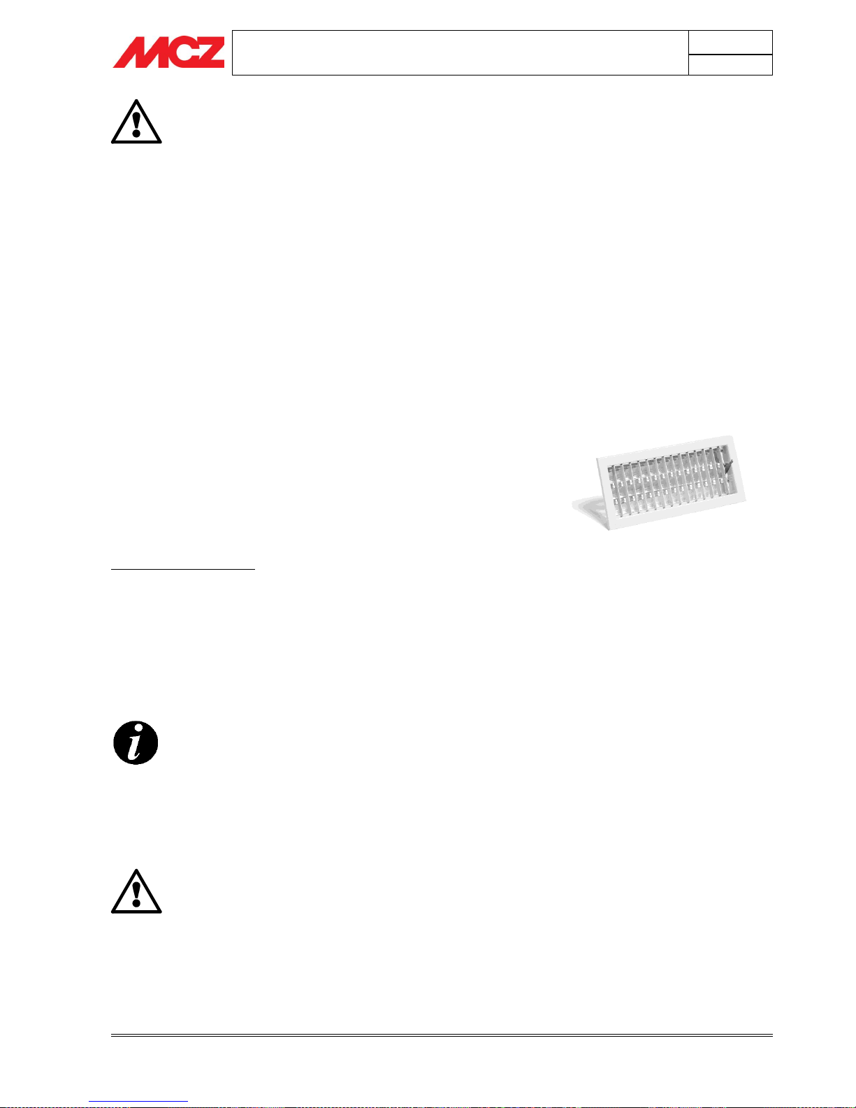
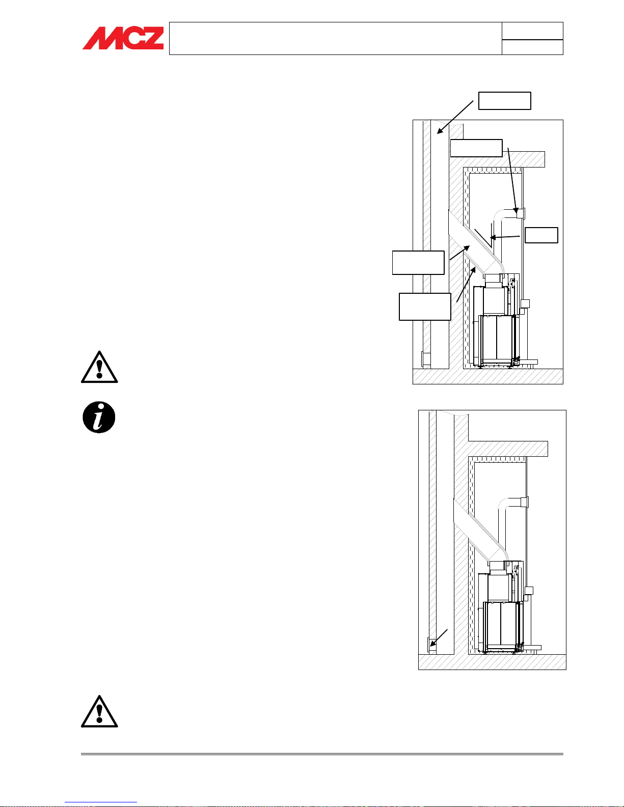
Example of fireplace stove connection
Flue pipe
Hood grille
Smoke
connection
Ceramic fibre
insulation
45° max
Typical diagram of a correctly laid flue pipe
with a chamber including a sealed hatch to
collect and remove solid materials produced
during combustion positioned at the foot of
the external rising section.
INSTALLATION AND USE MANUAL
Chapter 2
page 10
Theoretical notions for installation
Technical service – MCZ S.p.A. all rights reserved - Reproduction prohibited
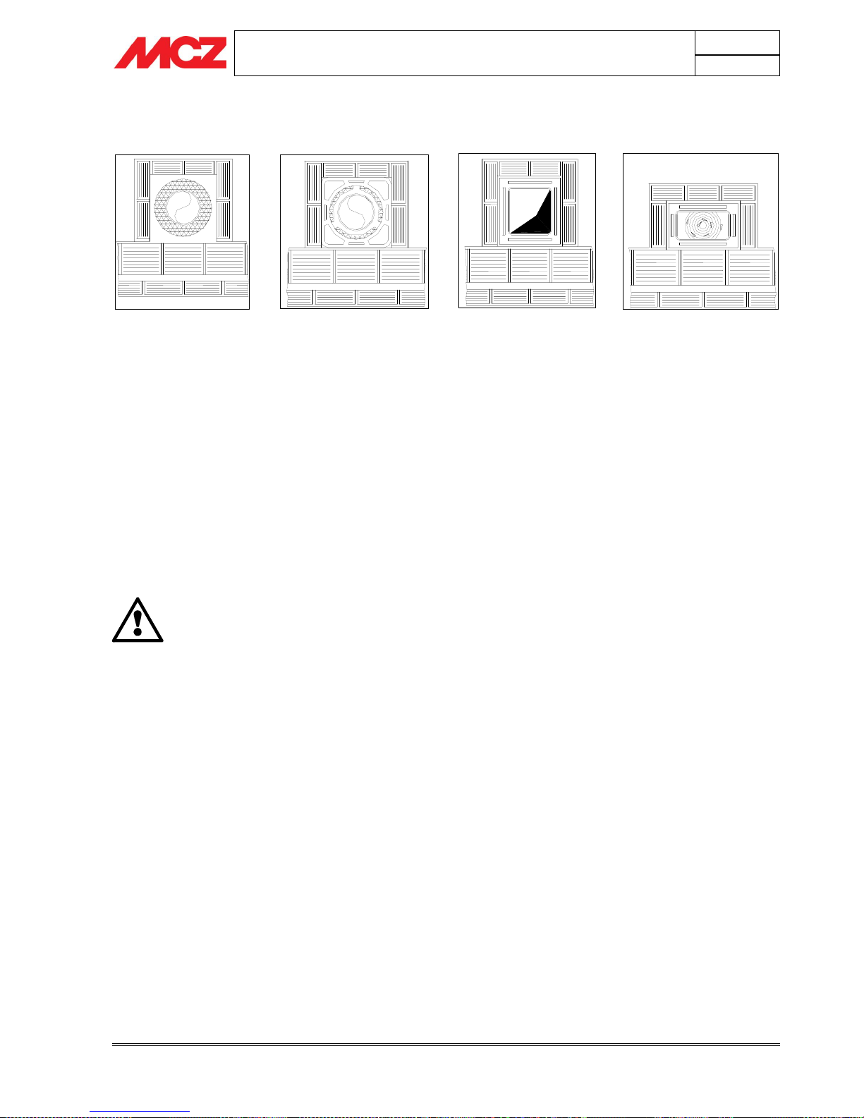
2.5.1. Examples of flue pipes
Square or rectangular section flue pipes must have rounded internal
corners with radius not less than 20mm. For the rectangular section,
the ratio between internal dimensions must be ≤1.5.
The sections/lengths of the flue pipe shown in the technical data table
are guidelines for correct installation. Any alternative configurations
must be suitably sized in accordance with EN13384-1.
The smoke duct should be equipped with a solid material collection
chamber at the mouth of the smoke duct to be easily opened with an
airtight door.
IMPORTANT !
In the event of doubt on your chimney flue operations or
that its dimensions are different from those recommended,
we highly suggest an authorised MCZ technician inspect and
measure chimney flue performance (micro-gauge
measurements)
MCZ s.p.a. shall not be held liable for poor operation of the
fireplace stove that is due to a flue pipe of improper size or
installation that does not comply with provided
requirements.
AISI 316 stainless steel
flue pipe with dual
chamber insulated with
ceramic wool or equivalent
resistant to 400°C.
EXCELLENT
Flue pipe in refractory brick
with insulated double wall and
external coat of cement mix
lightened with honeycomb
material such as clay.
GOOD
Traditional square section
clay flue pipe with insulating
hollow inserts.
GOOD
Avoid flue pipes with internal
rectangular sections whose
larger side is double the smaller
such as 20x40 or 15x30.
AVERAGE
INSTALLATION AND USE MANUAL
Chapter 2
page 11
Theoretical notions for installation
Technical service – MCZ S.p.A. all rights reserved - Reproduction prohibited
2.6. COWL
If underestimated, it is a severe impediment to correct "chimney
system" operations.
Flue pipe draught also depends on its cowl.
Therefore, if hand made, its four exhaust sections must correspond to
more than twice the internal section of the flue pipe.
Having to exceed the peak of the roof, the cowl will be exposed
to wind, therefore an industrial type is recommended.
The cowl must meet the following requisites:
It must have an internal section equal to that of the chimney.
It must have a useful output section not less that double that
of the internal section of the flue pipe.
It must be built to prevent rain, snow and any foreign objects
from getting into the flue pipe.
They must be installed to guarantee adequate smoke
dispersion and out of the reflux area where negative pressure
forms.
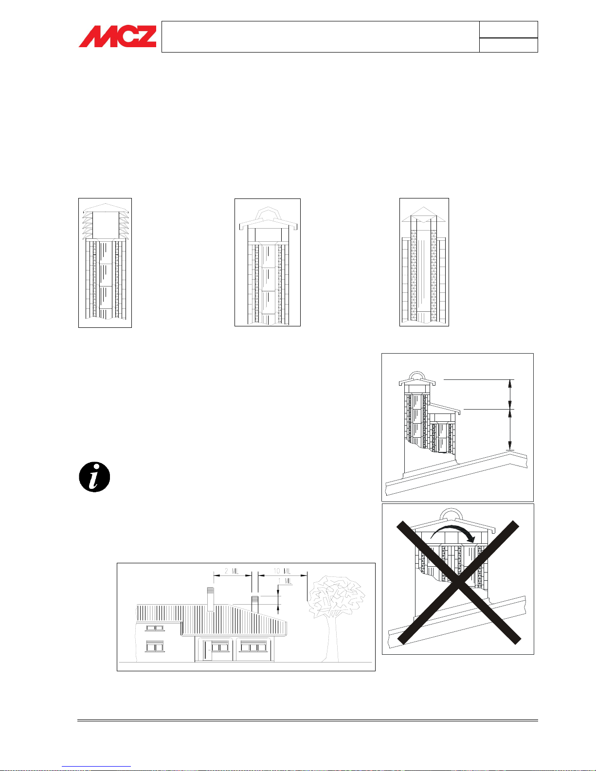
For paired flue pipes, the cowl for solid combustion
and the one for the upper floor must be at least 50cm
higher than the other to avoid pressure transfers
between paired flues.
The cowl must not have obstacles within 10 m such as
walls, roof slopes and trees. Otherwise, raise it at least
1 m over the obstacle and, in the event of other nearby
cowls, keep them at least 2 m away. In any case, the
cowl must exceed the peak of the roof by at least 1m.
An industrial cowl,
with prefabricated
sections fitting
together, allows
optimal disposal of
the flue gases.
A traditional
handmade cowl.
The right exhaust
section must be at
least twice the
internal section of
the flue pipe, 2.5
times is ideal.
Steel cowl for flue pipe
with internal smoke
deflector cone.
1
m
t
0
,
5
m
t
INSTALLATION AND USE MANUAL
Chapter 4
page 12
Installation and assembly
Technical service – MCZ S.p.A. all rights reserved - Reproduction prohibited
3. DIMENSIONS AND TECHNICAL SPECIFICATIONS
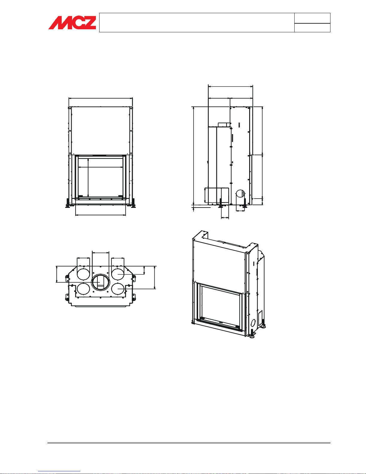
3.1. Dimensions of the Forma Wood 65
766
538
5
1
6
602
534
260 274
6
4
6
1
3
1
9
5
8
6
.
5
83.5
100
90
35
1
9
5
2
1
9
3
0
6
.
5
150
150
200
1
1
1
.
5
INSTALLATION AND USE MANUAL
Chapter 4
page 13
Installation and assembly
Technical service – MCZ S.p.A. all rights reserved - Reproduction prohibited
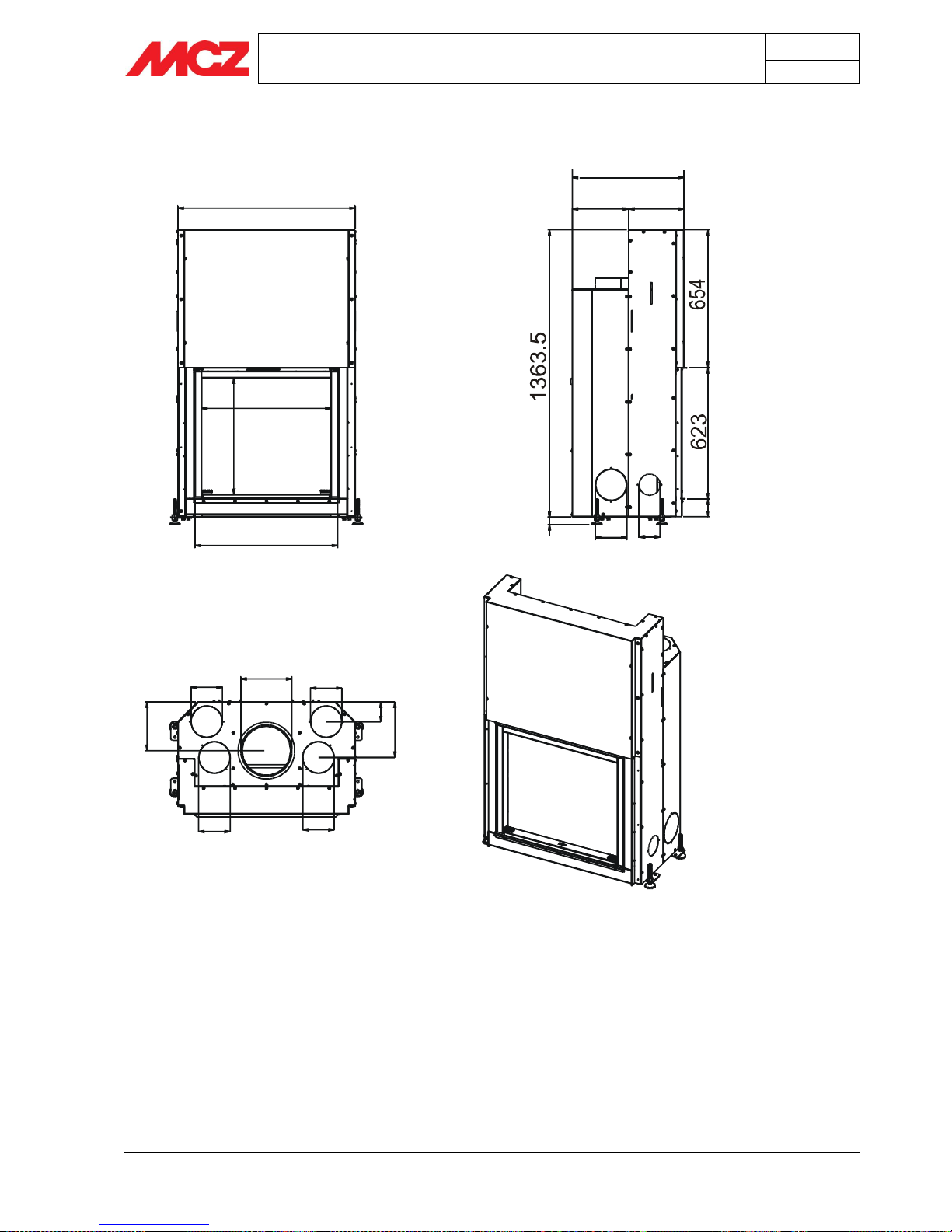
3.2. Dimensions of the Forma Wood 75
846
618
5
5
3
682
532
263
269
83.5
100
150
3
5
150
2
6
3
.
8
9
3
.
8
250
150
150
150
2
3
1
.
5
INSTALLATION AND USE MANUAL
Chapter 4
page 14
Installation and assembly
Technical service – MCZ S.p.A. all rights reserved - Reproduction prohibited
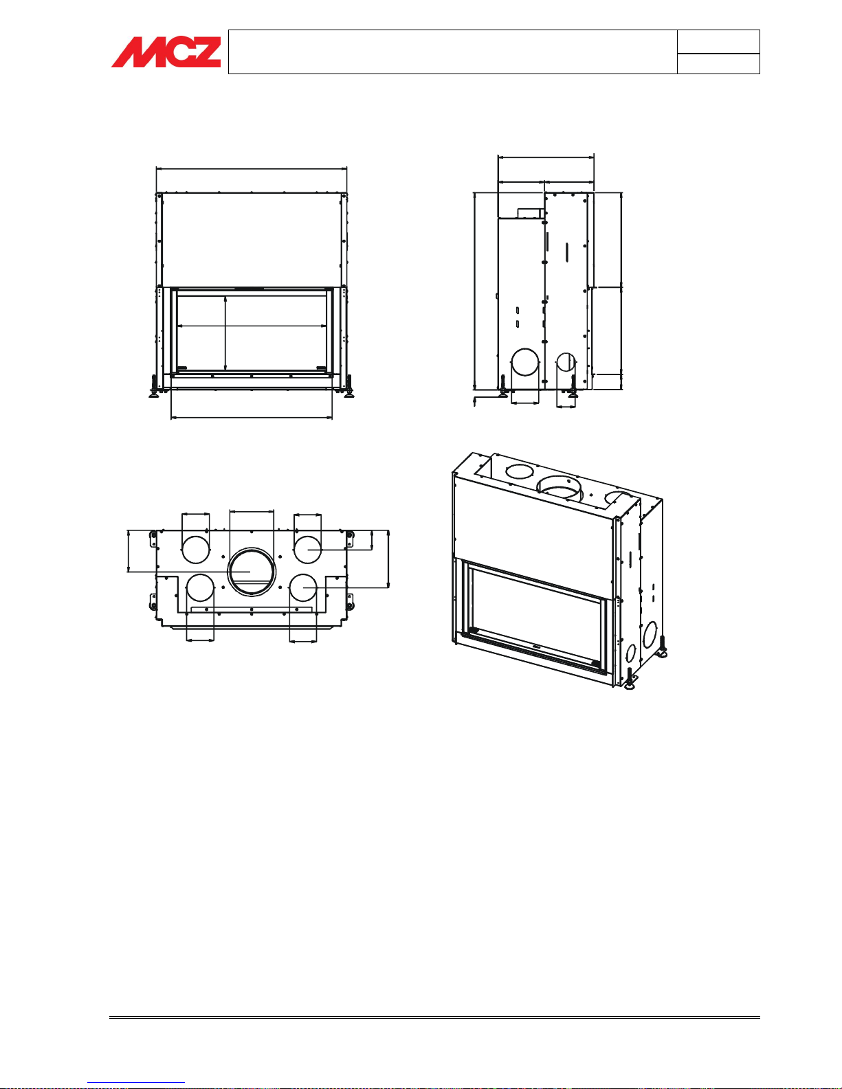
3.3. Dimensions of the Forma Wood 95
1056
828
4
1
1
892
532
256.5
275.5
5
2
4
.
5
4
8
2
83.5
100
150
35
150
250
150
2
3
1
.
5
150
150
3
1
8
.
8
1
0
8
.
8
1
0
9
3
 Loading...