

Page 1

Introduction
Technical service - Rights reserved MCZ GROUP S.p.A. - Reproduction prohibited
8901137200
EN
USE AND MAINTENANCE
MANUAL
PART 1 - REGULATIONS AND ASSEMBLY
Page 2

PELLET STOVES
Chapter 1
INSTALLATION AND USE MANUAL
page 2
Introduction
Technical service - Rights reserved MCZ GROUP S.p.A. - Reproduction prohibited
INTRODUCTION .................................................................................................................................... 3
1. WARNINGS AND GUARANTEE CONDITIONS ..................................................................................... 4
1.1. SAFETY INSTRUCTIONS .................................................................................................................... 4
1.2. OPERATING WARNINGS .................................................................................................................... 5
1.3. WARNINGS FOR THE CORRECT DISPOSAL OF THE PRODUCT ............................................................. 6
1.4. GUARANTEE CONDITIONS ................................................................................................................ 7
1.4.1. Limitations ................................................................................................................................. 7
1.4.2. Exclusions .................................................................................................................................. 7
2. THEORETICAL NOTIONS FOR INSTALLATION ................................................................................... 9
2.1. Pellets .............................................................................................................................................. 9
2.2. PRECAUTIONS FOR INSTALLATION ................................................................................................. 10
2.3. OPERATING AREA ........................................................................................................................... 11
2.4. CONNECTION TO THE EXTERNAL AIR INTAKE ................................................................................. 11
2.5. CONNECTION OF SMOKE DISCHARGE PIPE ...................................................................................... 12
2.6. CONNECTION TO THE FLUE PIPE .................................................................................................... 14
2.7. CONNECTION TO AN EXTERNAL FLUE WITH INSULATED OR DOUBLE-WALL PIPE .............................. 14
2.8. OPERATING PROBLEMS CAUSED BY DRAUGHT DEFECTS IN THE FLUE .............................................. 15
2.9. PLUMBING CONNECTION ................................................................................................................ 16
3. INSTALLATION AND ASSEMBLY ...................................................................................................... 17
3.1. DRAWINGS AND TECHNICAL CHARACTERISTICS.............................................................................. 17
3.1.1. EGO HYDRO Dimensions .......................................................................................................... 17
3.1.2. STAR HYDRO Dimensions ......................................................................................................... 17
3.1.3. Dimensions of the HYDRO 15-22 version CLUB without domestic hot water production kit ............ 18
3.1.4. Dimensions of the HYDRO 22 version CLUB equipped with kit for domestic hot water production. . 18
3.1.5. Dimensions of the HYDRO 15-22 version SUITE without domestic hot water production kit ........... 19
3.1.6. Dimensions of the HYDRO 22 version SUITE equipped with kit for domestic hot water production. 19
3.1.7. Dimensions of the HYDRO 15-22 version MUSA without domestic hot water production kit ........... 20
3.1.8. Dimensions of the HYDRO 22 version MUSA equipped with kit for domestic hot water production. 20
3.1.9. Technical characteristics ........................................................................................................... 21
3.2. PREPARATION AND UNPACK ING .................................................................................................... 24
3.3. LATERAL CLADDING ASSEMBLY ....................................................................................................... 27
3.3.1. Assembly of profiles for inserting the steel sides-EGO ................................................................. 27
3.3.2. Assembly of profiles for inserting the ceramic and soapstone sides-STAR ..................................... 28
3.3.3. Assembly of the lower panel – Suite and Club Stoves ................................................................. 29
3.3.4. Installation of side tiles - Suite and Club Stoves ......................................................................... 30
3.3.5. Installation of ceramic top - Suite and Club Stoves ..................................................................... 30
3.3.6. Assembly of sides on the MUSA stove ........................................................................................ 31
3.4. PLUMBING SYSTEM CONNECTION ................................................................................................... 32
3.4.1. Connections to the system ........................................................................................................ 34
3.4.2. System filling ........................................................................................................................... 35
3.4.3. Water characteristics ................................................................................................................ 35
3.5. KIT FOR DOMESTIC HOT WATER PRODUCTION (Optional) Only for Suite/Club/Musa stoves ............... 36
3.6. EXAMPLE INSTALLATION DIAGRAMS ............................................................................................... 37
3.6.1. Installation diagram for heating system without domestic hot water kit
(EGO/STAR/SUITE/CLUB/MUSA) ............................................................................................................. 37
3.6.2. Installation diagram for heating system with domestic hot water kit (SUITE/CLUB/MUSA) ............ 38
3.6.3. Heating installation diagram in combination with a boiler ............................................................ 39
3.6.4. Heating installation in combination with a storage tank............................................................... 39
3.7. INSTALLATION OF AIR FILTER ........................................................................................................ 44
3.8. OPENING/CLOSING THE DOOR ....................................................................................................... 44
3.9. MAKING THE ELECTRICAL CONNECTIONS ....................................................................................... 44
Page 3
PELLET STOVES
Chapter 1
INSTALLATION AND USE MANUAL
page 3
Introduction
Technical service - Rights reserved MCZ GROUP S.p.A. - Reproduction prohibited
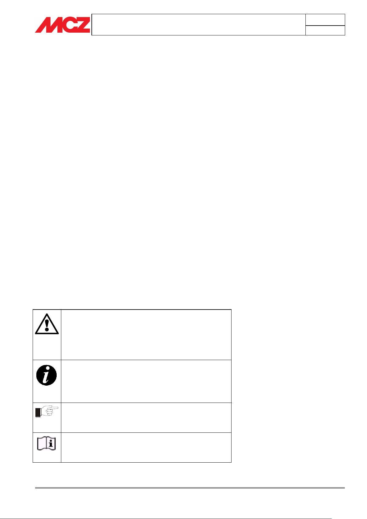
ATTENTION
This warning sign indicates that the message to which it
refers should be carefully read and understood, because
failure to comply with what these notices say can cause
serious damage to the stove and put the user's safety at
risk.
INFORMATION
This symbol is used to highlight information which is
important for proper stove operation. Failure to comply with
these provisions will compromise use of the stove and its
operation will not be satisfactory.
OPERATING SEQUENCES:
Indicates a sequence of buttons to be pushed to access
menus or to make adjustments.
MANUAL
Indicates that you should carefully read this manual or the
related instructions.
INTRODUCTION
Dear Customer,
We wish to thank you for choosing an MCZ product, specifically a stove
of the MCZ pellet line.
In order to get the best performance from your stove and to
enjoy to the full the warmth and the sense of well-being which
the flame will diffuse through the home, we recommend that
you read this booklet carefully before lighting the stove for the
first time.
While thanking you again, may we remind you that the stove MUST
NOT be used by children, and that they must always be kept at a safe
distance from it!
Revisions to the publication
In order to improve the product, to keep this publication up to date the
manufacturer reserves the right to make modifications without any
advance notice. Any reproduction, even in part, of this manual without
the consent of the manufacturer is prohibited.
Care of the manual and how to consult it
Take good care of this manual and keep it in a place which can
easily and quickly be reached.
If this manual should be lost or destroyed, or if it is in poor
condition, ask for a copy from your retailer or directly from the
manufacturer, providing product identification data.
Information which is essential or that requires special attention is
shown in bold text.
Italic text
is used to call your attention to other paragraphs in the
manual or for any additional clarifications.
SYMBOLS USED IN THE MANUAL
Page 4

PELLET STOVES
Chapter 1
INSTALLATION AND USE MANUAL
page 4
Warnings and guarantee conciliations
Technical service - Rights reserved MCZ GROUP S.p.A. - Reproduction prohibited
Installation of the stove, making the electrical
connections, checking its operation, and
maintenance are all tasks which should be carried
out by qualified and authorised personnel.
Install the stove in accordance with the
regulations in force in your local area, region and
country.
This apparatus cannot be used by people
(including children with limited physical, sensorial
or mental abilities or with little experience and
know-how unless they have been viewed or
instructed on the use of the apparatus by the
person responsible for its safety.
A bad use or unproper maintainance of the product
can bring to a serious risk of explosion in the
combustion chamber.
For the correct use of the stove and of the electronic
apparatus connected to it, and to prevent accidents, the
instructions given in this booklet must always be
followed.
Use, adjustment and programming must be carried out
by adults. Errors or incorrect settings may cause
hazardous conditions and/or poor operation.
Before beginning any operation, the user, or whoever is
preparing to operate on the stove, must have read and
understood the entire contents of this instruction booklet.
The stove is to be used only for its intended purpose. Any
other use is to be considered improper and therefore
hazardous.
Do not use the stove for standing on or as any kind of
support.
Do not put clothes to dry on the stove, any clothes
hangers and suchlike must be kept a suitable distance
from the stove. Danger of fire.
All responsibility for improper use is taken entirely by the
user and such use relieves MCZ of any civil or criminal
responsibility.
Any kind of tampering or unauthorised substitution of
non-original spare parts can be hazardous for the safety
of the operator and relieves MCZ of any civil or criminal
responsibility.
Most of the surfaces of the stove are extremely hot (the
door, the handle, the glass, smoke discharge pipes etc.).
Avoid coming into contact with these parts, therefore,
without adequate protective clothing or suitable
implements, such as gloves with thermal protection or
implements which keep the hands cool.
Under no circumstances should the stove be run
with the door open or the glass broken.
Do not touch the stove with wet hands, in view of the
fact that it is an electrical appliance. Always disconnect
the supply cable before doing anything to the unit.
Before carrying out any cleaning or maintenance
operation, make sure in advance that the stove is
1. WARNINGS AND GUARANTEE CONDITIONS
1.1. SAFETY INSTRUCTIONS
Page 5
PELLET STOVES
Chapter 1
INSTALLATION AND USE MANUAL
page 5
Warnings and guarantee conciliations
Technical service - Rights reserved MCZ GROUP S.p.A. - Reproduction prohibited
disconnected from the mains electricity supply, by turning
off the main switch located on the back of the stove, or
by unplugging the supply cable.
The stove must be connected to an electrical system
which is equipped with an earth conductor.
The system must be of adequate rated capacity for the
stated electrical power of the stove.
Incorrect installation or faulty maintenance (not
conforming to the requirements set out in this booklet)
can cause harm to people, animals or property. In such
cases MCZ is absolved from any civil or criminal
responsibility.
Live electrical parts: only power the product after
completing assembly.
Disconnect the product from the 230V power supply
before performing any maintenance operation.
IF ANY SMOKE SPILLAGE IS SEEN WITHIN THE
ROOM OR THE APPLIANCE SUFFERS FROM AN
EXPLOSIVE IGNITION PLEASE TURN OFF THE
APPLIANCE, VENTILATE THE ROOM AND CONTACT
THE INSTALLER/ SERVICE ENGINEER
IMMEDIATELY.
Shut the stove down in the event of a breakdown
or bad running and contact the engineer
immediately.
Pellets must not be fed manually into the burner
– this wrong behaviour can generate an
abnormal amount of unburned gas, with a risk of
explosion in the chamber.
Accumulated unburnt pellets in the burner after a
failed ignitions must be removed before lighting.
Failure too clean and maintain the brazier can result in
improper running and explosions within the stove. Make
sure you remove and clear the holes in the brazier and
any loose encrustations every time you empty the ash
from the stove or every time you have a failed
ignition.Make sure that the holes in the brazier are
never reduced in size as this will affect the safe
performance of the stove if not maintained.
Do not wash the inside of the stove with water.
Do not wash the stove with water. The water could get
inside the unit and damage the electrical insulation and
cause electric shocks.
A carbon monoxide alarm must be fitted in the
room where the appliance is sited Refer too ADJ
part 2.34 through too 2.36 page 41
Do not expose your own body to hot air for extended
periods. Do not overheat the room you are in and
where the stove is installed. This could cause injuries
and health problems.
Do not expose plants or animals directly to a current of
hot air. Both plants and animals could be harmed by it.
Do not put any fuels in the hopper but wood pellets.
Install the stove in a location which is suitable for
firefighting, and equipped with all services such as air
ONLY FOR UK
1.2. OPERATING WARNINGS
Page 6

PELLET STOVES
Chapter 1
INSTALLATION AND USE MANUAL
page 6
Warnings and guarantee conciliations
Technical service - Rights reserved MCZ GROUP S.p.A. - Reproduction prohibited
and electricity supply and provision for discharging
combustion gases.
If there is a fire in the flue pipe, extinguish the
stove, disconnect it from the power supply and
never open the door. Then contact the competent
authorities.
If the stove and the ceramic cladding are in storage, it
should be in a place that is free of damp, and they
should not be exposed to extremes of temperature.
It is inadvisable to base the stove directly on the floor,
and if the floor is made of flammable material, it must
be suitably insulated.
Do not light the stove with flammable materials
if the ignition system breaks down.
INFORMATION
In case of any problems, get in touch with your
dealer, or a qualified engineer authorised by
MCZ, and if a repair is necessary, insist on the
use of original spare parts.
Use only the fuel recommended by MCZ (for Italy
pellets with a diameter of 6 mm and for other
European countries with a diameter of 6-8 mm) and
provided only with an automatic supply system.
Periodically check and clean the smoke outlet ducts
(connection to the flue pipe).
Accumulated unburnt pellets in the burner after
repeated failed ignitions must be removed before
lighting.
The pellet stove is not a cooking appliance.
Always keep the cover of the fuel hopper closed.
Keep this instruction manual carefully because it
must stay with the stove throughout its working life.
If the stove is sold or transferred to another user,
always make sure that the booklet goes with the
product.
If it gets lost, ask MCZ or your authorised dealer for
another copy.
1.3. WARNINGS FOR THE CORRECT DISPOSAL OF
THE PRODUCT
The owner is the sole party responsible for demolishing and disposing of
the product. This must be performed in compliance with laws related to
safety and environmental protection in force in his/her country.
At the end of its working life, the product must not be disposed of as
urban waste.
It must be taken to a special differentiated waste collection centre set
up by the local authorities or to a retailer that provides this service.
Separating and recycling prevents potential negative effects on the
environment and health (often caused by inappropriately disposing of
product parts). It also allows materials to be recovered in order to
obtain significant savings in energy and resources.
Page 7
PELLET STOVES
Chapter 1
INSTALLATION AND USE MANUAL
page 7
Warnings and guarantee conciliations
Technical service - Rights reserved MCZ GROUP S.p.A. - Reproduction prohibited
MCZ guarantees the stove, excluding the components
which are subject to normal wear and tear, for a
period of two years from the date of purchase, as proved by
a supporting document which gives the name of the vendor
and the date on which the sale took place. The guarantee is
conditional on the guarantee certificate being filled in and
returned within 8 days, and requires that the product be
installed and tested by a specialised installer, according to
the detailed instructions given in the instruction booklet
supplied with the product.
The term 'guarantee' is to be understood to denote the freeof-charge replacement or repair of parts recognised to
have been defective at the start by reason of
manufacturing defects.
In order to activate the product warranty the
commissioning document which is supplied with the
appliance and also is available as a download from
the Specflue website must be filled in correctlty and
returned within 14 days.
ONLY FOR UK
1.4. GUARANTEE CONDITIONS
1.4.1. Limitations
The above guarantee does not cover components relating to electrical
and electronic parts, or fans, on which the guarantee period is 1 year
from the purchase of the product, documented as specified above. The
guarantee does not cover parts subject to normal wear such as gaskets,
glass, and any parts with can be removed from the firebox.
The replacement parts will be guaranteed for the remainder of the
guarantee period starting from the date of purchase of the product.
1.4.2. Exclusions
Variations in colour in the painted or ceramic parts, and crackling of the
glaze on the ceramics, do not constitute grounds for a claim under the
guarantee, as they are natural characteristics of the material and of the
use of the product.
The guarantee does not cover any parts which may be found to be
faulty as a result of negligence or carelessness in use, or of incorrect
maintenance, or of installation not complying with MCZ's specification
(see the relevant chapters in this user manual).
MCZ refuses to accept any responsibility for any damage which may be
caused, directly or indirectly, by persons, animals or things in
consequence of the failure to observe all the prescriptions laid down in
the instruction booklet, especially those concerning warnings on the
subject of installation, use and maintenance of the appliance.
If the product does not perform correctly, contact your local retailer
and/or importer.
Damage caused by transport and/or handling is excluded from the
guarantee.
For installation and use of the product, reference must be made
exclusively to the booklet supplied.
The guarantee will be invalidated in the event of damage caused by
tampering with the appliance, atmospheric agents, natural disasters,
electrical discharges, fire, defects in the electrical system, and caused
Page 8

PELLET STOVES
Chapter 1
INSTALLATION AND USE MANUAL
page 8
Warnings and guarantee conciliations
Technical service - Rights reserved MCZ GROUP S.p.A. - Reproduction prohibited
CLAIMS UNDER THE GUARANTEE
the request for action under the guarantee must be
addressed to the retailer, who will forward the claim
to MCZ's technical assistance service.
MCZ refuses to accept any responsibility in the event
that the stove or any other accessory have been
improperly used or modified without authorisation.
For all replacement of parts, only original MCZ spare
parts must be used.
by lack of, or incorrect, maintenance in terms of the manufacturer's
instructions.
Page 9
PELLET STOVES
Chapter 2
INSTALLATION AND USE MANUAL
page 9
Theoretical notions for installation
Technical service - Rights reserved MCZ GROUP S.p.A. - Reproduction prohibited
The poorer the quality of the fuel, the more often the
internal parts of the brazier and combustion chamber
must be cleaned.
The company strongly recommends using certified
fuel for its products (ENplus, DINplus, Ö-Norm
M7135).
Poor quality pellets or others that do not comply with
the characteristics specified previously may
compromise the operation of your product and can
therefore render the guarantee and product liability
invalid.
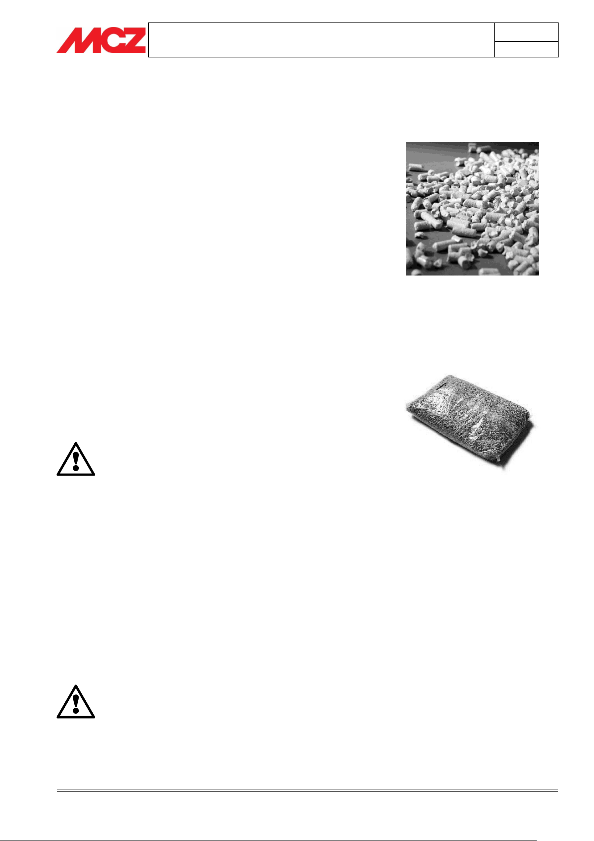
Fuel pellets
15 Kg sack of fuel
2. Theoretical notions for installation
The instructions contained in this chapter explicitly refer to the
regulations of the Italian installation Standard UNI 10683. In
any case, always comply with the regulations in force in the
country of installation.
2.1. Pellets
Wood pellets are manufactured by hot-extruding compressed sawdust
which is produced during the working of natural dried wood. The
compactness of the material is guaranteed by the lignin contained in
the wood itself and allows pellets to be produced without glue or
binders.
The market offers different types of pellets with characteristics that vary
according to the wood mixtures used. The most common diameter on
the market is 6 mm (although 8 mm diameter is available too) with a
length, on average, of between 3 and 40 mm. A good quality pellet has
a density of between 600 and 750 or more kg/metres cubed and a
water content that accounts for 5 to 8% of its weight.
Pellets have technical advantages besides being an ecological fuel, as
the wood residue is used completely, thereby achieving cleaner
combustion than that of fossil fuels.
Good-quality wood has a calorific value of 4.4 kW/kg (15% moisture,
after about 18 months of seasoning), whereas that of pellets is 4.9
kW/kg. To ensure good combustion, the pellets must be stored in a dry
place and protected from dirt. Pellets are usually supplied in 15 kg bags,
therefore, storing them is very convenient.
Good quality pellets guarantee good combustion, thereby decreasing
harmful emissions into the atmosphere.
The main quality certifications for pellets currently available on the
European market guarantee that the fuel complies with class A1/A2
according to ISO 17225-2. (formerly EN 14961). These certifications
include, for example, ENPlus, DINplus, Ö-Norm M7135, and in
particular, guarantee the following characteristics:
calorific value: 4.6 ÷ 5.3 kWh/kg.
Moisture content: ≤ 10% of the weight.
Percentage of ash: max 1.2% of the weight (A1 less than
0.7%).
Diameter: 6±1/8±1 mm.
Length: 3÷40 mm.
Content: 100% untreated wood without the addition of binding
substances (max 5% bark).
Packaging: in sacks made from ecologically compatible or
biologically decomposing material.
Page 10
PELLET STOVES
Chapter 2
INSTALLATION AND USE MANUAL
page 10
Theoretical notions for installation
Technical service - Rights reserved MCZ GROUP S.p.A. - Reproduction prohibited
IMPORTANT!
Installation and assembly of the stove must be
carried out by qualified personnel.
IMPORTANT!
The stove must be connected to a flue pipe or a
vertical duct which can discharge the fumes at the
highest point of the building.
The fumes are however derived from the combustion
of wood products, and if they come into contact with
or close to walls, they can make dirty marks.
Also take care because the fumes are very hot but
almost invisible, and can cause burns on contact.
The holes for the passage of the smoke pipe and for
the intake of air from outside should be made before
positioning the stove unit.
2.2. PRECAUTIONS FOR INSTALLATION
The stove must be installed in a suitable position to allow the normal
operations of opening and ordinary maintenance.
The site must be:
capable of providing the environmental conditions for operation
equipped with power supply 230V 50 Hz
capable of taking an adequate system for smoke discharge
provided with external ventilation
provided with an earth connection complying with CEI
The stove must be connected to a flue pipe or an internal or
external vertical duct conforming to EN 1856-1-2 to suit the
appliance and types of fuels to be burnt – refer to detailed
guidance in sections 2, 3 and 4 in ADJ (ONLY FOR UK).
The stove must be positioned in such a way that the electrical
plug is accessible.
Page 11
PELLET STOVES
Chapter 2
INSTALLATION AND USE MANUAL
page 11
Theoretical notions for installation
Technical service - Rights reserved MCZ GROUP S.p.A. - Reproduction prohibited
It is not permissible to install the stove in bedrooms,
bathrooms, or in a room where another heating
appliance is installed (fireplace, stove etc.) which
does not have its own independent air intake.
Locating the stove in a room with an explosive
atmosphere is prohibited.
The floor of the room where the stove is to be
installed must be strong enough to take its weight.
If the flooring is made of wood, provide a floor
protection surface in compliance with current
national standards.
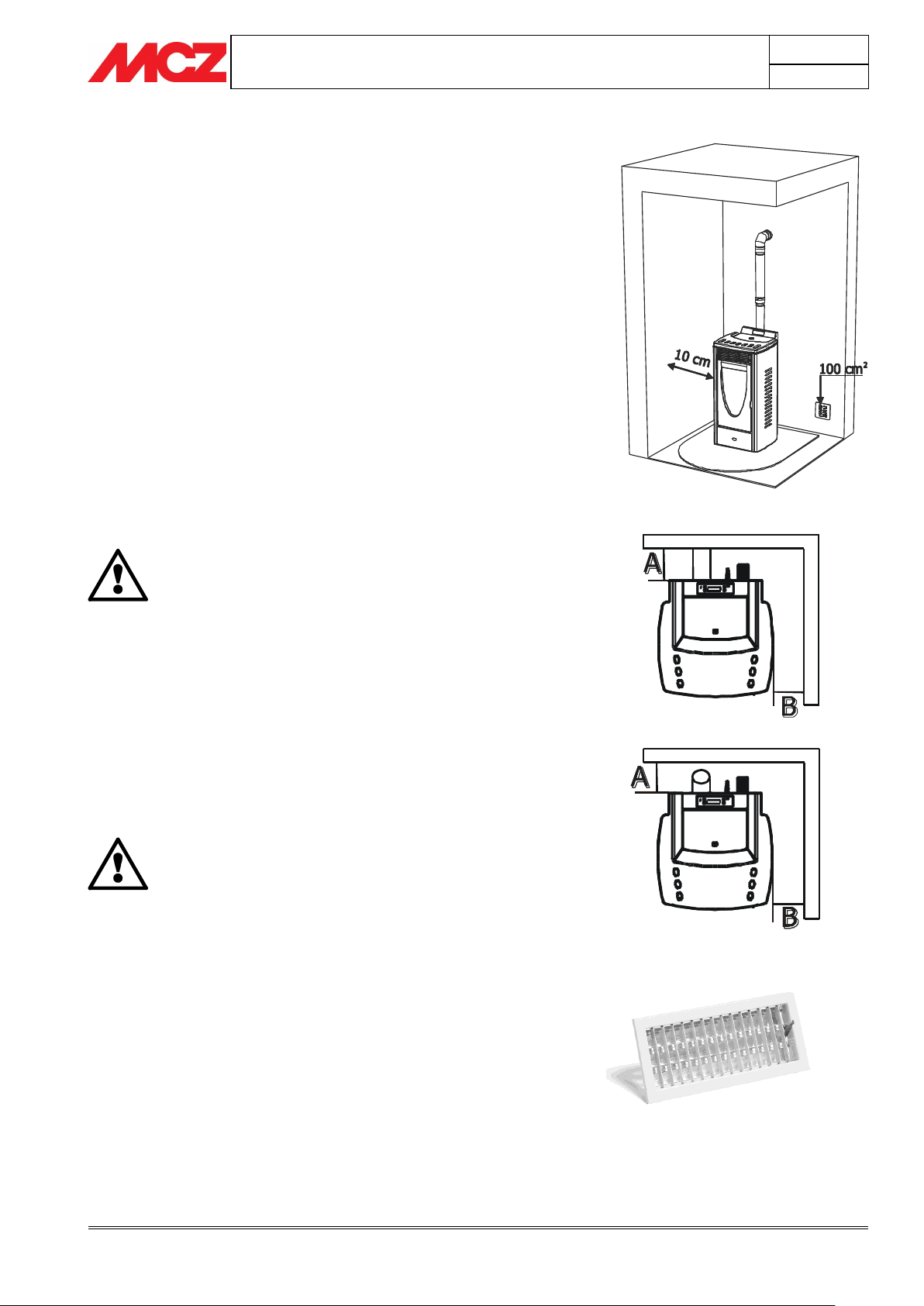
Example of pellet stove installation
Example of pellet stove installation
2.3. OPERATING AREA
For proper functioning and a good temperature distribution, the stove
should be positioned in a location where it is able to take in the air
necessary for combustion of the pellets (about 40 m3/h must be
available), as laid down in the standard governing the installation and in
accordance with local national standards.
The volume of the room must not be less than 30 m3.
The air must come in through permanent openings made in walls (in
proximity to the stove) which give onto the outside, with a minimum
cross-section area of 100 cm2.
These openings must be made in such a way that it is not possible for
them to be obstructed in any way.
Alternatively, the air can be taken from rooms adjacent to the one
which needs ventilating, as long as they are provided with an air intake
from the outside, and are not used as bedrooms or bathrooms, and
provided there is no fire risk such as there is for example in garages,
woodsheds, and storerooms, with particular reference to what is laid
down in current standards.
If walls are flammable, maintain a minimum distance of 10cm at the
rear (A), 10cm at the side (B) and 100 cm at the front.
If the room contains objects which are believed to be particularly
delicate, such as drapes, sofas and other furniture, their distance from
the stove should be considerably increased.
2.4. CONNECTION TO THE EXTERNAL AIR INTAKE
It is essential that at least as much air must be able to flow into the
room where the stove is installed as is required for proper combustion
in the appliance and for the ventilation of the room. This can be
effected by means of permanent openings in the walls of the room to
be ventilated, which give onto the outside, or by single or collective
ventilation ducts.
For this purpose, on the external wall near the stove, a hole must be
made with a minimum free cross-section of 100 cm². (equivalent to a
round hole of 12 cm diameter or a square hole 10x10 cm), protected by
a grille on the inside and the outside.
The air intake must also:
communicate directly with the room where the stove is installed
Page 12
PELLET STOVES
Chapter 2
INSTALLATION AND USE MANUAL
page 12
Theoretical notions for installation
Technical service - Rights reserved MCZ GROUP S.p.A. - Reproduction prohibited
2
1
Pipes and unions with suitable gaskets must always
be used, to guarantee a hermetic seal.
All sections of the smoke duct must be inspectable and
removable to enable periodic internal cleaning. Tee
connectors with inspection caps should be used.
ONLY FOR UK
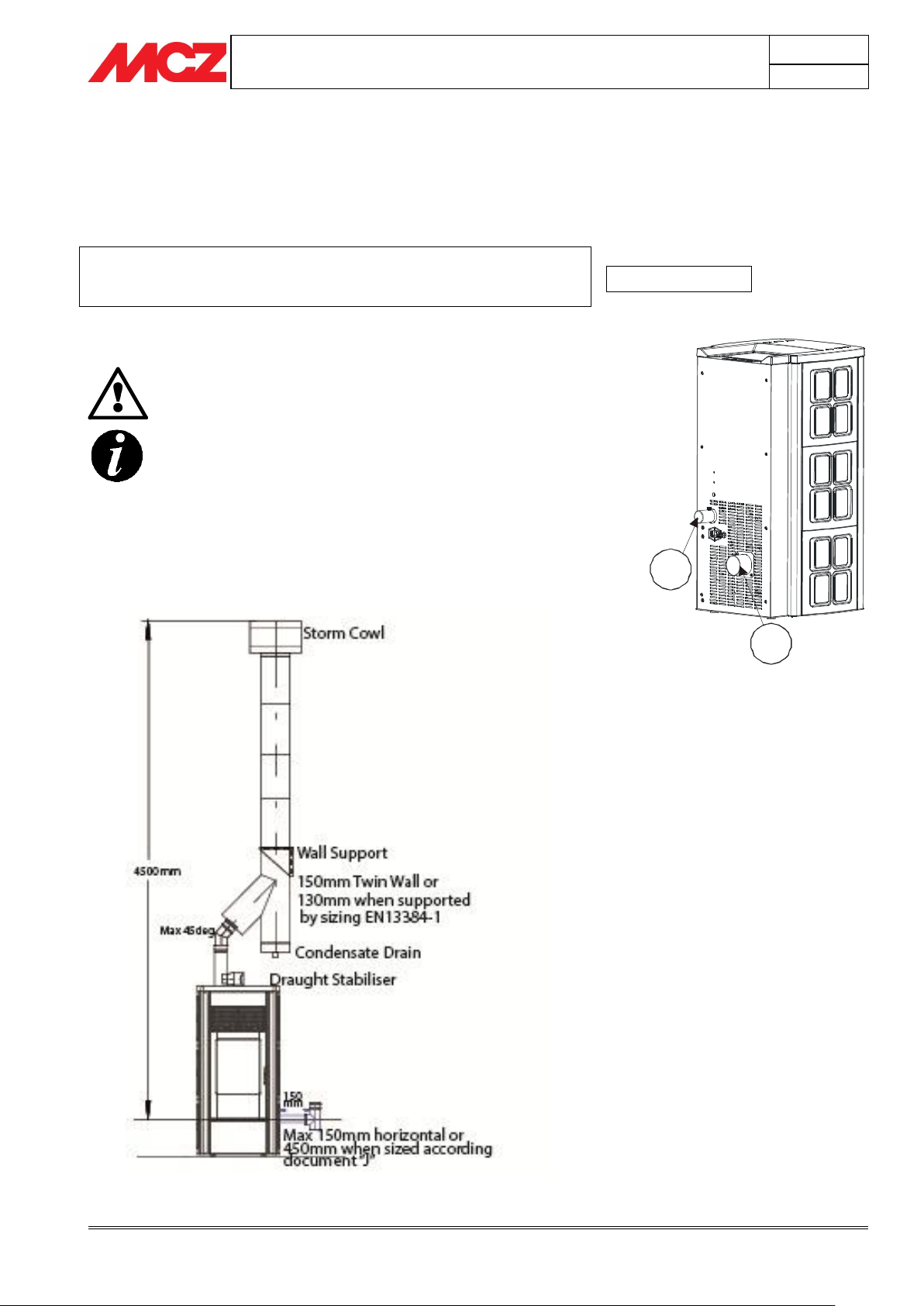
Example of pellet stove installation
Be protected by a grille, metal mesh or suitable guard, as long as
this does not reduce the area below the minimum.
be positioned in such a way as to be impossible to obstruct
2.5. CONNECTION OF SMOKE DISCHARGE PIPE
We recommend the use 100mm single wall connecting flue pipe.
All exterior flue or flue used internaly above 1.8m should be twin wall
insulated pipe installed in accordance with ADJ reference page 23
section 1.31 and 1.32 and 1.33 & Hetas regulations.
The combustion chamber works in low pressure. The smoke duct for
the discharge of fumes will also be under low pressure when connected
to an efficient flue pipe as directed.
Position the stove bearing in mind all the instructions and considerations
above.
Page 13
PELLET STOVES
Chapter 2
INSTALLATION AND USE MANUAL
page 13
Theoretical notions for installation
Technical service - Rights reserved MCZ GROUP S.p.A. - Reproduction prohibited
IMPORTANT!
A 90 degree change of direction in the flue pipe must
be fitted with suitable tee connectors to allow the
possibility of inspection. (see accessories for pellet
stove)
It is absolutely prohibited to fit a grille on the end of
the discharge pipe, because it could lead to poor
running of the stove.
FOR CONNECTION TO THE FLUE PIPE, NOT MORE
THAN 150mm OF HORIZONTAL PIPE MUST BE USED
AND NOT MORE THAN 4 x 45° bends MUST BE USED.
I accordance with UK Building Regulations.
ONLY FOR UK
Page 14

PELLET STOVES
Chapter 2
INSTALLATION AND USE MANUAL
page 14
Theoretical notions for installation
Technical service - Rights reserved MCZ GROUP S.p.A. - Reproduction prohibited
This type of connection ensures the evacuation of the
fumes even in the event of a temporary power cut.
This type of connection ensures the evacuation of the
fumes even in the event of a temporary power cut.
0,5 mt.
1
2
3
1) Windproof cowl
2) Flue pipe
3) Inspection
0,5 mt.
2
1
3
1) Windproof cowl
2) Flue pipe
3) Inspection
ONLY FOR UK
2.6. CONNECTION TO THE FLUE PIPE
. In the event of larger dimensions, or of the flue pipe being in poor
condition (for example cracks, poor insulation, etc.), it is advisable to fit
a stainless steel pipe of suitable diameter inside the flue pipe
throughout its length, right up to the top.
At the bottom of the flue pipe, provide an inspection cap to allow
periodic checking and cleaning, which must be done annually.
Make a gas-tight connection to the flue pipe, using pipes and
connectors as recommended by us.
You must ensure that a windproof cowl should be fitted which complies
with the standards in force.
2.7. CONNECTION TO AN EXTERNAL FLUE WITH
INSULATED OR DOUBLE-WALL PIPE
The external fluepipe must have internal dimensions of a minimum of
150mm, and maximum 180mm.
Check with suitable instruments that there is a minimum draught
of 5 Pa. on low fire and 10pa on high fire. The flue must always
run under negative pressure and a cold flue pull of – 2>3 pascals
must be secured.
The only type of pipe which is permissible is insulated (double-walled)
stainless steel, smooth on the inside, fixed to the wall. At the bottom of
the flue pipe, provide an inspection cap to allow periodic checking and
cleaning, which must be done annually. Make a gas-tight connection
to the flue pipe, using pipes and connectors as recommended by us.
You must ensure that a windproof cowl should be fitted which complies
with the standards in force.
Page 15
PELLET STOVES
Chapter 2
INSTALLATION AND USE MANUAL
page 15
Theoretical notions for installation
Technical service - Rights reserved MCZ GROUP S.p.A. - Reproduction prohibited
IMPORTANT!
The operation of the pellet stove is noticeably
sensitive to the conformation and position of the flue
which is adopted.
Hazardous conditions can only be overcome by
suitable setting-up of the stove carried out by
qualified MCZ personnel.
1
2 3
4
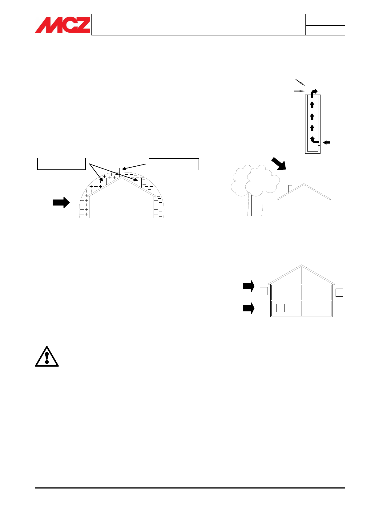
E.g. Crosswind 2: 8 m/sec
Depression of 30Pa
E.g. Downdraft at 45° of
8m/sec. Overpressure of 17
Pa
1-2 = High-pressure zones
3-4 = Low-pressure zones
WIND
Least favourable points
Most favourable position
WIND
Downdraft
High-pressure zone
Low-pressure zone
2.8. OPERATING PROBLEMS CAUSED BY DRAUGHT
DEFECTS IN THE FLUE
Of all the weather and geographical conditions which affect the
operation of a flue pipe (rain, fog, snow, altitude a.s.l., exposure to
sunlight, direction of facing), the wind is unquestionably the most
decisive. In fact, along with thermal depression caused by the
difference in temperature inside and outside of the chimney, there is
another type of depression or over-pressure: dynamic pressure caused
by the wind. An updraft always increases depression and hence
draught. A crosswind increases depression provided the cowl has been
installed properly. A downdraft always decreases depression, at times
inverting it.
Besides the direction and force of the wind, the position of the flue and
the cowl with respect to the roof of the building and the surrounding
landscape is important.
The wind also influences the operation of the chimney indirectly by
creating high-pressure and low-pressure zones, not only outside the
building but inside as well. In rooms directly exposed to the wind (2),
an indoor high-pressure area can be created which can augment the
draught in stoves and fireplaces, but it can be counteracted by the
external high pressure if the cowl is situated on the side exposed to the
wind (1). On the other hand, in the rooms on the opposite side from
the direction of the wind (3), a dynamic depression can be created
which competes with the natural thermal depression developed by the
chimney, but this can be compensated for (sometimes) by locating the
flue on the opposite side from the direction of the wind (4).
Page 16
PELLET STOVES
Chapter 3
INSTALLATION AND USE MANUAL
page 16
Installation and assembly
Technical service - Rights reserved MCZ GROUP S.p.A. - Reproduction prohibited
IMPORTANT!
The connection of the stove to the plumbing
system must be carried out ONLY by specialized
personnel who are capable of carrying out
installation properly, in compliance with current
standards in the country of installation.
It is important that ONLY qualified engineers are
used to fit and commission the appliance in ALL
cases. The installing engineer MUST hold a QCF
recognised biomass qualification. Any company
using sub-contractors MUST ensure they also hold
the relevant qualifications.
If installation of the stove will involve interaction
with another, pre-existing system complete with
heating equipment (gas boiler, methane boiler,
fuel oil boiler, etc.), it is even more advisable to
call in qualified personnel, who subsequently will
be responsible for conformity of the system with
current applicable law.
MCZ will not be held responsible for damage to
persons or things in the event of failed or incorrect
operation if the aforementioned warnings are not
complied with.
ONLY FOR UK
2.9. PLUMBING CONNECTION
For connection of the plumbing system to the stove, the user should
refer to chapter 3, INSTALLATION AND ASSEMBLY; specifically,
paragraph 3.4, CONNECTION TO PLUMBING SYSTEM
Page 17
PELLET STOVES
Chapter 3
INSTALLATION AND USE MANUAL
page 17
Installation and assembly
Technical service - Rights reserved MCZ GROUP S.p.A. - Reproduction prohibited
Ø
Ø
Ø
Ø
3. INSTALLATION AND ASSEMBLY
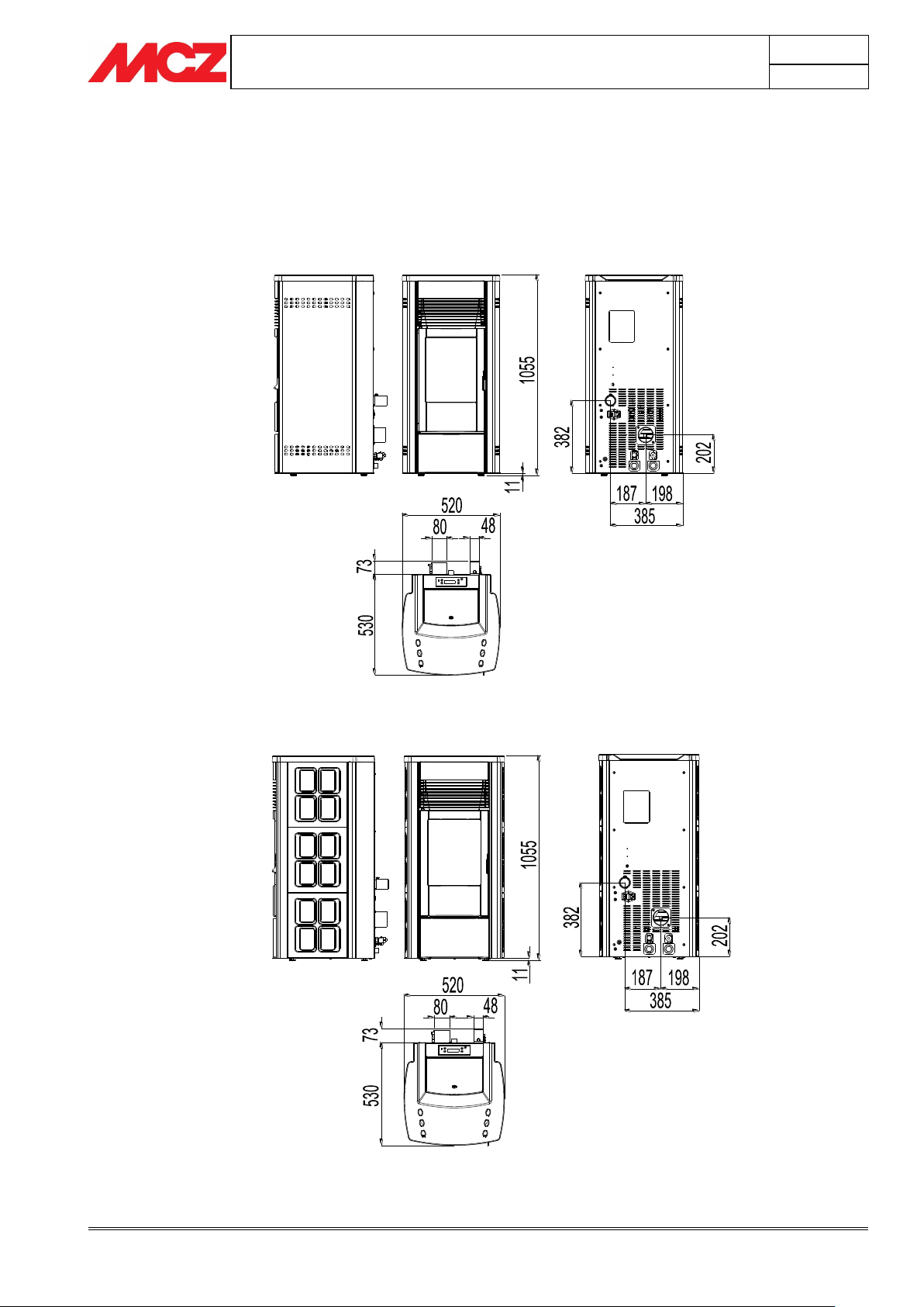
3.1. DRAWINGS AND TECHNICAL CHARACTERISTICS
3.1.1. EGO HYDRO Dimensions
3.1.2. STAR HYDRO Dimensions
Page 18
PELLET STOVES
Chapter 3
INSTALLATION AND USE MANUAL
page 18
Installation and assembly
Technical service - Rights reserved MCZ GROUP S.p.A. - Reproduction prohibited
Ø
Ø
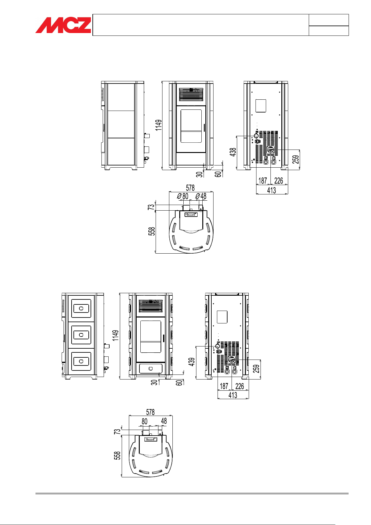
3.1.3. Dimensions of the HYDRO 15-22 version CLUB without domestic hot
water production kit
3.1.4. Dimensions of the HYDRO 22 version CLUB equipped with kit for domestic
hot water production.
Page 19
PELLET STOVES
Chapter 3
INSTALLATION AND USE MANUAL
page 19
Installation and assembly
Technical service - Rights reserved MCZ GROUP S.p.A. - Reproduction prohibited
Ø
Ø
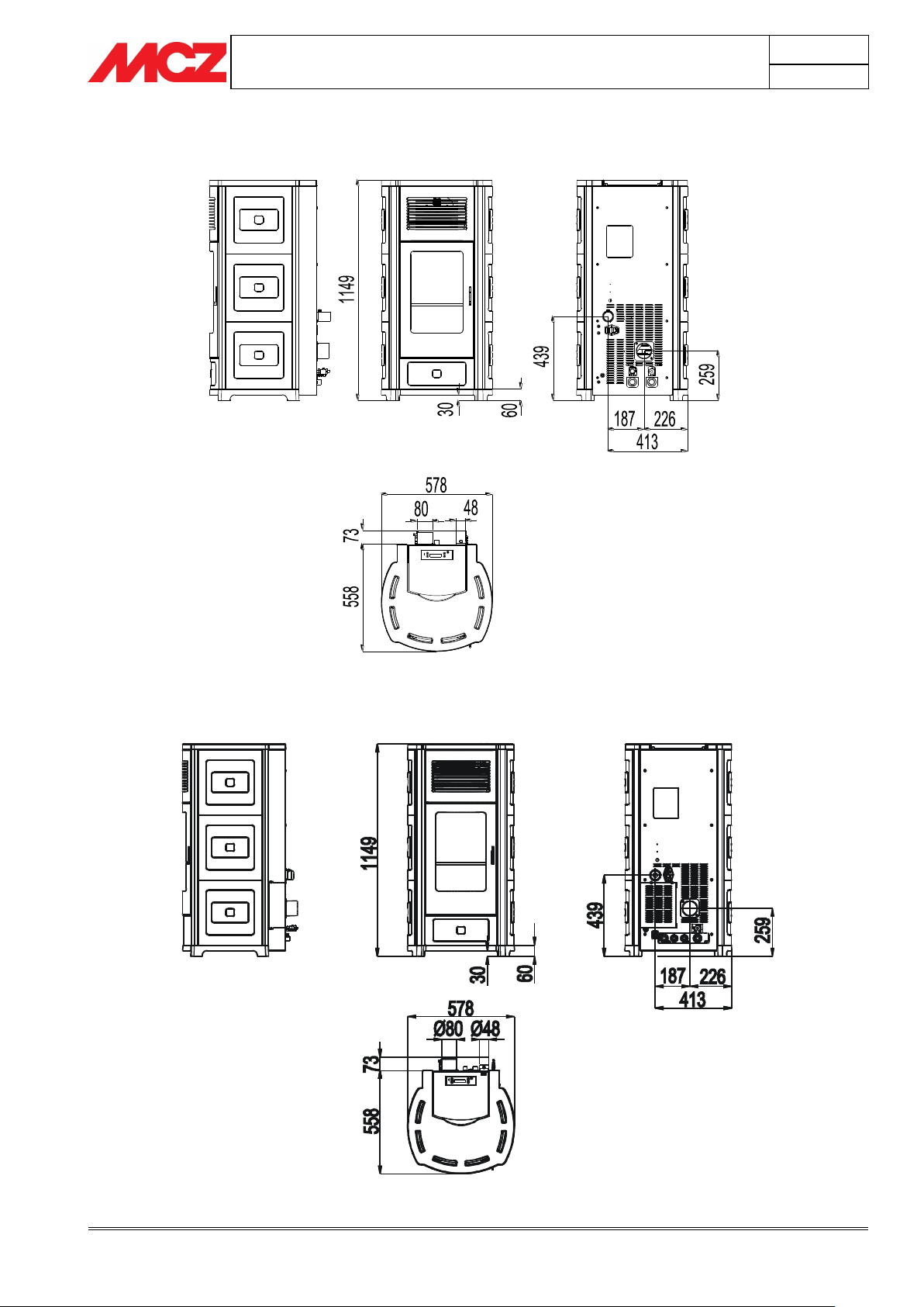
3.1.5. Dimensions of the HYDRO 15-22 version SUITE without domestic hot
water production kit
3.1.6. Dimensions of the HYDRO 22 version SUITE equipped with kit for
domestic hot water production.
Page 20
PELLET STOVES
Chapter 3
INSTALLATION AND USE MANUAL
page 20
Installation and assembly
Technical service - Rights reserved MCZ GROUP S.p.A. - Reproduction prohibited
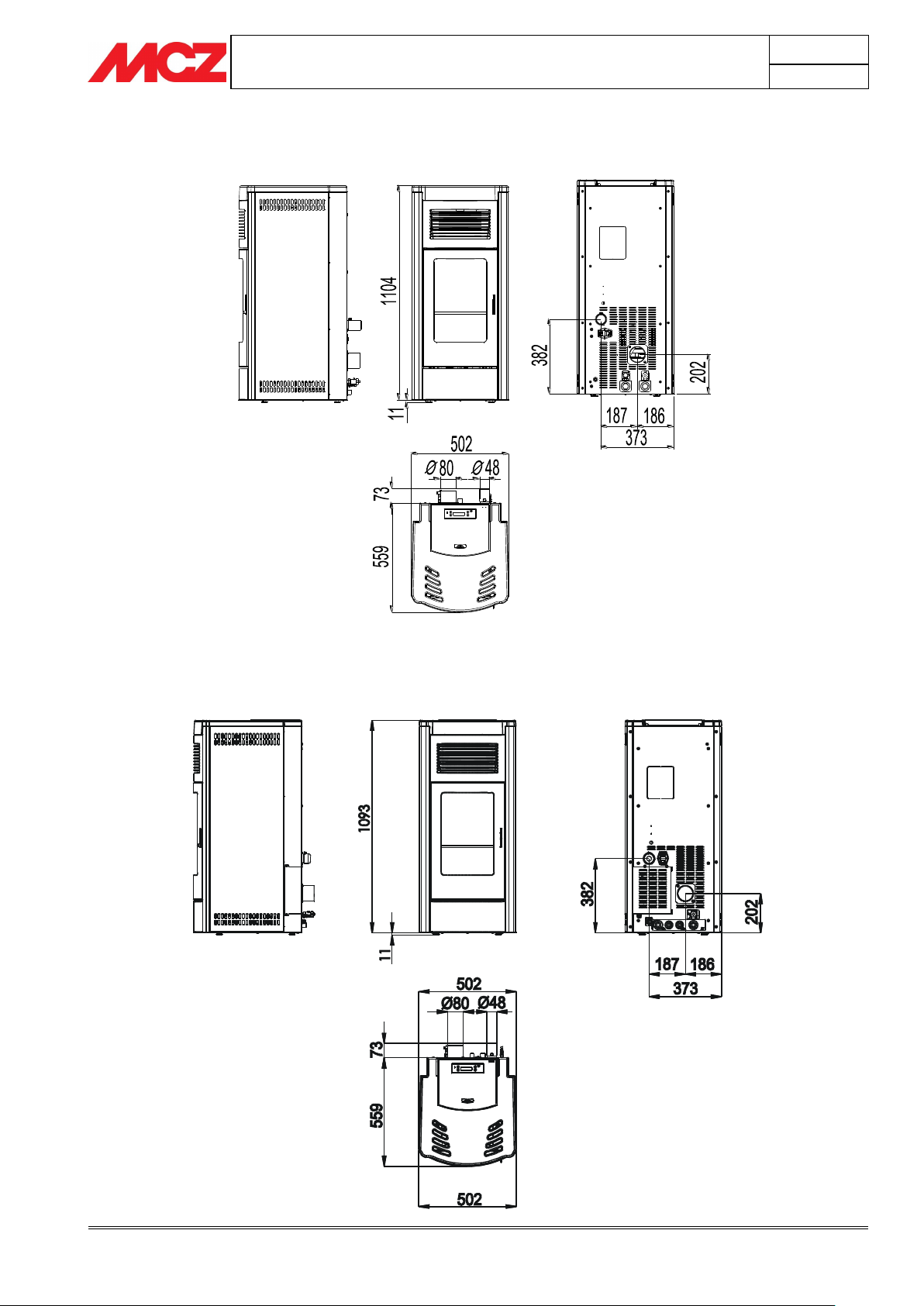
3.1.7. Dimensions of the HYDRO 15-22 version MUSA without domestic hot
water production kit
3.1.8. Dimensions of the HYDRO 22 version MUSA equipped with kit for
domestic hot water production.
Page 21
PELLET STOVES
Chapter 3
INSTALLATION AND USE MANUAL
page 21
Installation and assembly
Technical service - Rights reserved MCZ GROUP S.p.A. - Reproduction prohibited
FOR THE HYDRAULIC PIPE OUTPUT DRAWINGS, SEE
PAGES 31-32
Technical characteristics
Ego Hydro / Star Hydro
Nominal thermal power
11,6 kW (9976 kcal/h)
Nominal output power (H2O):
10,0 kW (8600 kcal/h)
Minimum output power
3,6 kW (3096 kcal/h)
Minimum output power (H20)
2,5 KW (2150 kcal/h)
Yield at maximum
91,5%
Yield at minimum
96,0%
Temperature of exhaust smoke at maximum
140°C
Temperature of exhaust smoke at minimum
70°C
Particulate/OGC / Nox (13%O2)
11 mg/Nm3 - 3 mg/Nm3 - 168 mg/Nm3
CO at 13%O
²
at minimum and maximum
0,034 — 0,011%
CO2 at minimum and maximum
6,7% – 8,7%
Mass of smoke
9,4 g/sec
Maximum water pressure
2,5 bar - 250 kPa
Recommended draught at Max*** power
0,10 mbar – 10 Pa***
Minimum draft allowed at minimum power
0,02 mbar – 2 Pa
Hopper capacity
37 litres
Fuel pellet type
Pellet diameter 6-8 mm. Length range 3-40 mm
Pellet consumption per hour
Min ~ 0,8 kg/h * Max. ~ 2,5 kg/h *
Operating time between re-fuelling
Al min ~ 36 h * Al max. ~ 10 h *
Heatable volume m3
249/40 – 285/35 – 333/30 **
Combustion air inlet
External diameter 50 mm.
Smoke outlet
External diameter 80 mm.
Air intlet
80 Cm2
Rated electrical power (EN 60335-1)
120 W (Max 420 W)
Power supply frequency and voltage
230 Volts / 50 Hz
Net weight
175 kg
Weight with packaging
185 Kg
Distance from combustible material (rear):
100 mm
Distance from combustible material (sides):
100 mm
3.1.9. Technical characteristics
* Data that may vary depending on the type of pellets used
** Volume that can be heated, according to the power requirement per m3 (respectively 40-35-30 Kcal/h per m3)
***Value recommended by the manufacturer (non-binding) for optimal product operation
Tested according to EN 14785 in accordance with European regulation for Construction Products (EU
305/2011).
Page 22
PELLET STOVES
Chapter 3
INSTALLATION AND USE MANUAL
page 22
Installation and assembly
Technical service - Rights reserved MCZ GROUP S.p.A. - Reproduction prohibited
Technical characteristics
Suite 15 Hydro / Club 15 Hydro / Musa 15 Hydro
Nominal thermal power
15,4 kW (13244 kcal/h)
Nominal output power (H2O):
13,0 kW (11180 kcal/h)
Minimum output power
4,4 kW (3784 kcal/h)
Minimum output power (H20)
3,0 KW (2580 kcal/h)
Yield at maximum
92,1%
Yield at minimum
95,0%
Temperature of exhaust smoke at maximum
145°C
Temperature of exhaust smoke at minimum
71°C
Particulate/OGC / Nox (13%O2)
1,5 mg/Nm3 – 0,32 mg/Nm3 - 123 mg/Nm3
CO at 13%O
²
at minimum and maximum
0,040 — 0,011%
CO2 at minimum and maximum
7,03% – 11%
Maximum water pressure
2.5 bar - 250 kPa
Mass of smoke
10,4 g/sec
Recommended draught at Max*** power
0,10 mbar – 10 Pa***
Minimum draft allowed at minimum power
0,02 mbar – 2 Pa
Hopper capacity
44 litres
Fuel pellet type
Pellet diameter 6-8 mm. Length range 3-40 mm
Pellet consumption per hour
Min ~ 0,9 kg/h * Max. ~ 3,4 kg/h *
Operating time between re-fuelling
Al min ~ 32 h * Al max. ~ 9 h *
Heatable volume m3
332/40 – 379/35 – 443/30 **
Combustion air inlet
External diameter 50 mm.
Smoke outlet
External diameter 80 mm.
Air intlet
80 Cm2
Rated electrical power (EN 60335-1)
120 W (Max 420 W)
Power supply frequency and voltage
230 Volts / 50 Hz
Net weight
190 kg
Weight with packaging
200 Kg
Distance from combustible material (rear):
100 mm
Distance from combustible material (sides):
100 mm
* Data that may vary depending on the type of pellets used
** Volume that can be heated, according to the power requirement per m3 (respectively 40-35-30 Kcal/h per m3)
***Value recommended by the manufacturer (non-binding) for optimal product operation
Tested according to EN 14785 in accordance with European regulation for Construction Products (EU
305/2011).
Page 23
PELLET STOVES
Chapter 3
INSTALLATION AND USE MANUAL
page 23
Installation and assembly
Technical service - Rights reserved MCZ GROUP S.p.A. - Reproduction prohibited
Technical characteristics
Suite 22 Hydro / Club 22 Hydro / Musa 22 Hydro
Nominal thermal power
22,3 kW (19178 kcal/h)
Nominal output power (H2O):
18,0 KW (15480 kcal/h)
Minimum output power
4,4 kW (3784 kcal/h)
Minimum output power (H20)
3,0 KW (2580 kcal/h)
Yield at maximum
92,5%
Yield at minimum
95,0%
Temperature of exhaust smoke at maximum
160°C
Temperature of exhaust smoke at minimum
71°C
Particulate/OGC / Nox (13%O2)
2 mg/Nm3 – 0,2 mg/Nm3 - 132 mg/Nm3
CO at 13%O
²
at minimum and maximum
0,040 — 0,012%
CO2 at minimum and maximum
7,03% – 12,49%
Maximum water pressure
2,5 bar - 250 kPa
Mass of smoke
12,6 g/sec
Recommended draught at Max*** power
0,10 mbar – 10 Pa***
Minimum draft allowed at minimum power
0,02 mbar – 2 Pa
Hopper capacity
44 litres
Fuel pellet type
Pellet diameter 6-8 mm. Length range 3-40 mm
Pellet consumption per hour
Min ~ 0,9 kg/h * Max. ~ 4,9 kg/h *
Operating time between re-fuelling
Al min ~ 28 h * Al max. ~ 5 h *
Heatable volume m3
481/40 – 550/35 – 642/30 **
Combustion air inlet
External diameter 50 mm.
Smoke outlet
External diameter 80 mm.
Air intlet
80 Cm2
Rated electrical power (EN 60335-1)
120 W (Max 420 W)
Power supply frequency and voltage
230 Volts / 50 Hz
Net weight
190 kg
Weight with packaging
200 Kg
Distance from combustible material (rear):
100 mm
Distance from combustible material (sides):
100 mm
* Data that may vary depending on the type of pellets used
** Volume that can be heated, according to the power requirement per m3 (respectively 40-35-30 Kcal/h per m3)
***Value recommended by the manufacturer (non-binding) for optimal product operation
Tested according to EN 14785 in accordance with European regulation for Construction Products (EU
305/2011).
Page 24
PELLET STOVES
Chapter 3
INSTALLATION AND USE MANUAL
page 24
Installation and assembly
Technical service - Rights reserved MCZ GROUP S.p.A. - Reproduction prohibited
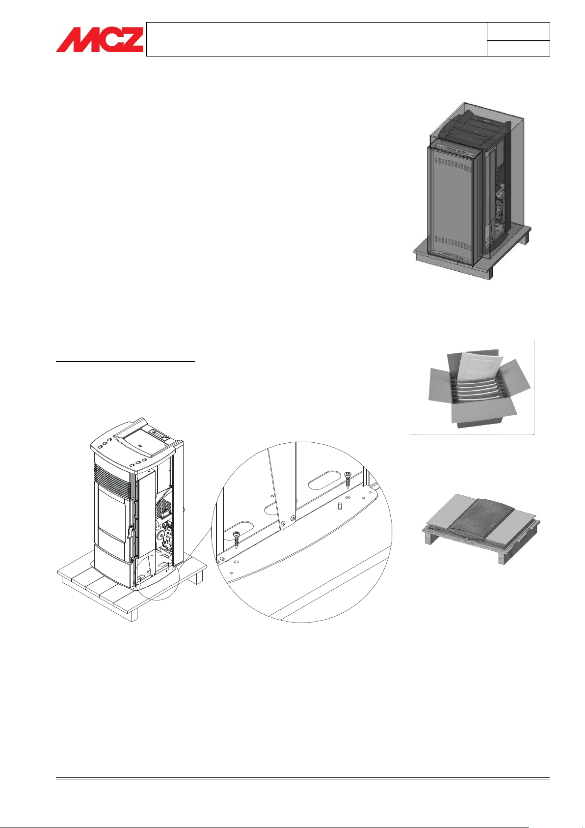
Figure 1 – Example of packaging stove
+ steel sides (Ego stove)
Figure 3 - Example of soapstone
packaging
Figure 4 - Removing packaging screws (in
figure Ego stove)
Figure 2 - Example of packing for
ceramics
3.2. PREPARATION AND UNPACK ING
STAR and EGO stoves are delivered with two different packagings:
The EGO and MUSA stove has one packaging
o It contains the stove and the steel sides with the
profiles (Fig.1)
The STAR stove has two packagings
o One contains the stove and the profile for the ceramic
or the soapstone
o One contains the ceramic (fig.2). In this case there will
be a single packaging for the structure (the cardboard
with the ceramics will be placed above the packaging
with the structure)
o or Soapstone (fig.3) (in this case there are two
packagings structure + soapstone pallet)
SUITE and CLUB stoves are delivered in two packages placed
on top of each other:
o the first contains the stove
o The second contains the ceramic cladding. (Fig. 2)
EGO/STAR and MUSA stoves
Open the packaging, remove the four screws that secure the base of
the stove to the pallet, two to the right and two to the left (see figure
4), and position the stove in the selected place, ensuring that it is
complies with the above instructions.
Page 25
PELLET STOVES
Chapter 3
INSTALLATION AND USE MANUAL
page 25
Installation and assembly
Technical service - Rights reserved MCZ GROUP S.p.A. - Reproduction prohibited
If the smoke outlet of the stove is forced or used
improperly to lift it or position it, the operation of the
stove can be damaged irreparably.
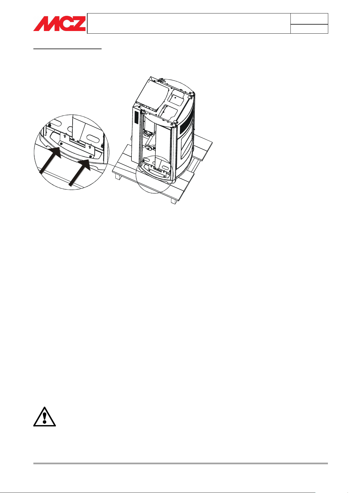
Figure 5 - Removing the packaging screws
(in figure Suite stove)
SUITE and CLUB stoves
Open the packaging, remove the two brackets that lock the stove to the
pallet (one on the right and one on the left side-fig.5)
The stove body or unit must always be kept in a vertical position when
moved, and moved only using carts. Special care must be used to
protect the door and the glass from impacts that would damage them.
Moving the product must always be done with care. If possible, unpack
the stove in the area where it is going to be installed.
The materials which make up the packaging are not toxic or harmful, so
no special procedures for disposal by required.
Their storage, disposal or possible recycling are therefore the responsibility of
the final user, in compliance with current legislation on the subject.
Do not store the stove unit or its cladding without their packaging.
Position the stove without its cladding and connect it to the flue pipe.
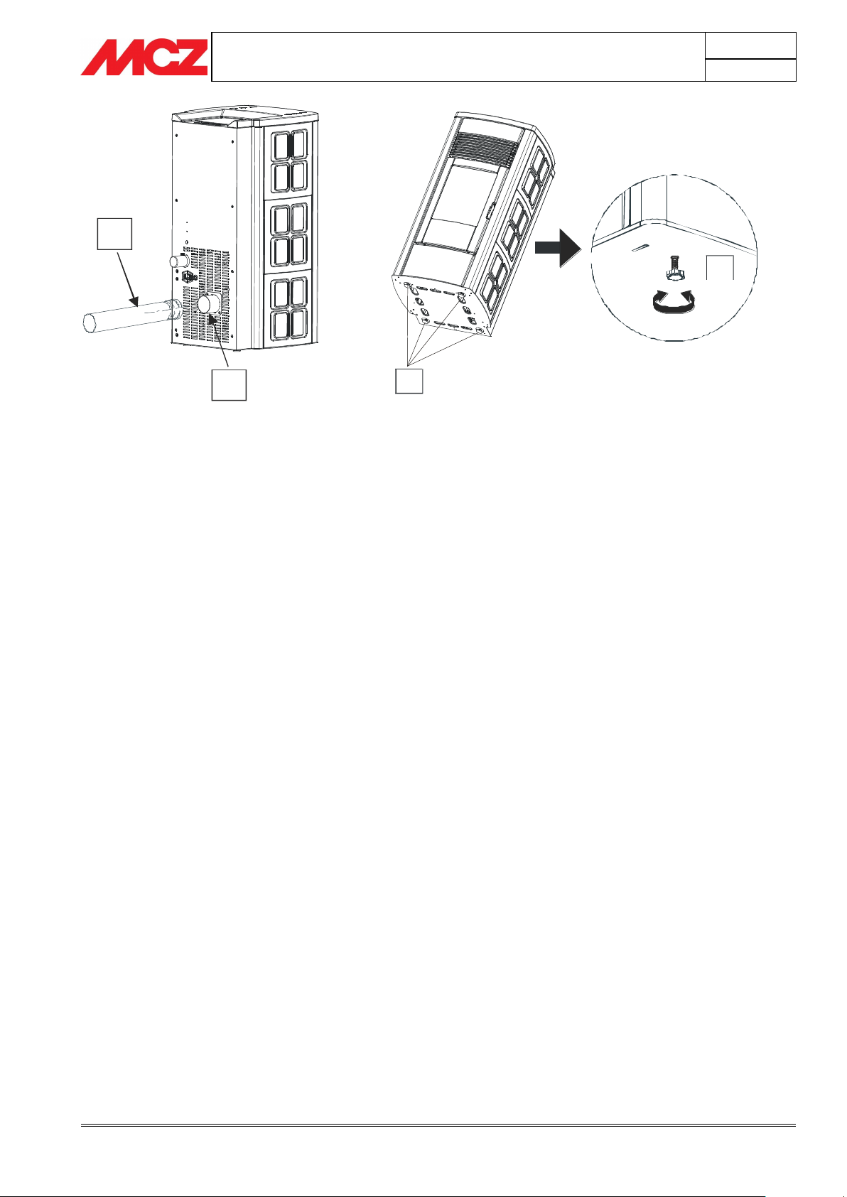
Use the four adjustable feet (J) to get the stove correctly levelled so
that the smoke outlet (S) is lined up with the connecting pipe (H).
Once the operations for connection are complete, assemble the
cladding (ceramics or steel sides).
If the stove needs to be connected to a discharge pipe which goes
through the rear wall (to connect up with the flue), take the greatest
care to make sure that the joint is not stressed.
Page 26
PELLET STOVES
Chapter 3
INSTALLATION AND USE MANUAL
page 26
Installation and assembly
Technical service - Rights reserved MCZ GROUP S.p.A. - Reproduction prohibited
J
J
S
H
1. Turn the feet clockwise to
lower the stove
2. Turn the feet counter-
clockwise to lower the stove
Page 27
PELLET STOVES
Chapter 3
INSTALLATION AND USE MANUAL
page 27
Installation and assembly
Technical service - Rights reserved MCZ GROUP S.p.A. - Reproduction prohibited
H
G
I
C
E
D
THE 6 CERAMICS AND THE 4 SIDES MADE OF
SOAPSTONE THAT ARE LATERAL TO THE STAR STOVE
ARE ALL THE SAME.
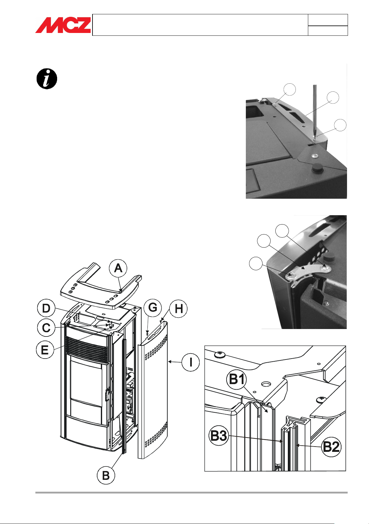
Figure 6 - EGO stove steel sides
3.3. LATERAL CLADDING ASSEMBLY
3.3.1. Assembly of profiles for inserting the
steel sides-EGO
Remove, on the upper part, the cast iron top (A).
Take the two profiles (B) to be assembled on the front part of the stove
(one to the right and one to the left). Make sure that the profile (B) at
the bottom enters the hole predisposed on the base for securing
purposes, and along the side enters the blade (B1) predisposed in the
stove along its entire height. Once this operation is performed, take the
piece (C) with the two screws (D and E) and secure the profile on the
top part of the stove. The screw (D) must be secured on the upper
sheet metal of the stove, while the screw (E) must be secured on the
area predisposed on the profile (B2).
Take the side (I) and secure it to the upper sheet metal of the stove
with the two screws (G and H) provided.
In the front part it must be inserted in the housing (B3) of the profile
(B).
Repeat the same operation for both sides. Reposition the cast iron top.
(fig.6)
Page 28
PELLET STOVES
Chapter 3
INSTALLATION AND USE MANUAL
page 28
Installation and assembly
Technical service - Rights reserved MCZ GROUP S.p.A. - Reproduction prohibited
You are advised to use small felt pads (two on the
right and two on the left) to be applied at the tips of
the ceramics (inwards) in correspondence to the part
of the tile that comes into contact with the sheet
metal profile (B3).
This prevents the ceramic from coming into contact
with the metallic parts of the structure and
compensates any differences in thickness of the tile.
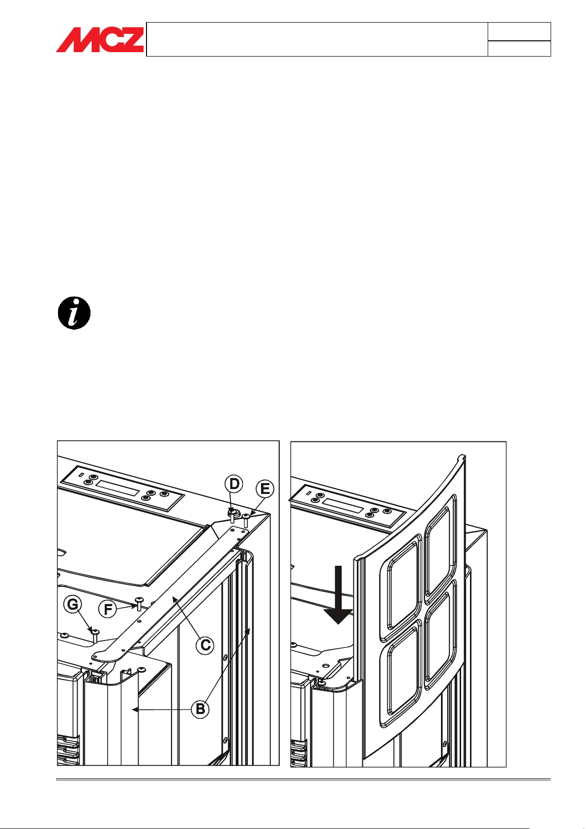
Figure 7 - STAR stove sides
3.3.2. Assembly of profiles for inserting the
ceramic and soapstone sides-STAR
Remove, on the upper part, the cast iron top (A).
Take the four profiles (B) to be assembled on the front and rear part of
the stove (two to the right and two to the left). Make sure that the
profile (B) at the bottom enters the in correspondence to the two holes
predisposed on the base for securing purposes, and along the side
enters the blade (B1) predisposed in the stove along its entire height.
Once both profiles are assembled on one side, take the piece (C) with
the four screws (D-E-F-G) and secure it on the upper part of the stove
(F-D) and in correspondence to the element predisposed on the profile
(B2) for screws G-E.
At this point take the ceramics (3 per side) or the soapstone (2 per
side) and insert them on the profile (B) in correspondence to the
element (B3) from above downwards. (fig.7)
Repeat the same operation for both sides. Reposition the cast iron top.
Page 29
PELLET STOVES
Chapter 3
INSTALLATION AND USE MANUAL
page 29
Installation and assembly
Technical service - Rights reserved MCZ GROUP S.p.A. - Reproduction prohibited
A
B
C
C
D
E
A
F
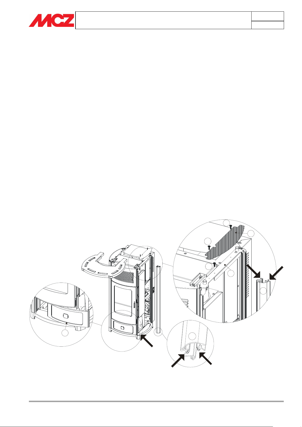
Figure 8 – Installation of lower front panel
3.3.3. Assembly of the lower panel – Suite and Club Stoves
The stove is delivered with all the ceramics packed. Therefore, before
assembling the side tiles and the top, it is necessary to insert the lower
panel.
Proceed in the following way:
Remove the micro-perforated sheet metal grill B on the right
side (handle side) on the upper part by removing the two
screws C.
Remove the screw D on the sheet metal E in a way that the
profile A is no longer locked.
At this point slightly lift the sheet metal E and remove the
profile A.
To remove the profile A lift it (sliding it from the base) and tilt
it slightly in a way that the plugs inserted on the base come
out.
Take the lower panel F and insert it from the right (handle
side) towards the left in a way that it enters exactly in the
housings
Reinsert the profile A making the plugs enter the case, and
lift the sheet metal E in a way to realign the profile “A”. Work
in a way that the upper plugs of the profile “A” are inserted in
the housings of the sheet metal “E”.
With the screw D close the sheet metal E that keeps profile A
locked (fig.8)
Before refitting the grill B with the two screws C, also insert
the side tiles (See par.3.3.4)
Page 30
PELLET STOVES
Chapter 3
INSTALLATION AND USE MANUAL
page 30
Installation and assembly
Technical service - Rights reserved MCZ GROUP S.p.A. - Reproduction prohibited
B
C
C
A
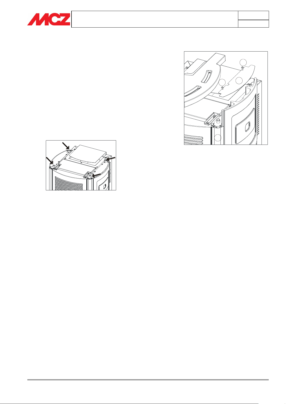
Fig.10 - Supports for installation of ceramic
top
Figura 9 – Installation of side tiles
3.3.4. Installation of side tiles - Suite and Club Stoves
Remove the micro-perforated grill B and insert the three side tiles,
making them slide from the top towards the bottom on the runners of
the profiles A. On the upper and lower part of the tile it is advisable to
place small felt pads. Level the bubbles of the tiles. At this point it is
possible the retighten the micro-perforated grill B to the structure and
position the ceramic top. (fig.9)
3.3.5. Installation of ceramic top - Suite and Club
Stoves
Install the top by setting it on the four upper protuberances of the
stove. The part underneath is provided with four small cavities at the
rubber supports indicated in the figure
. (fig.10)
Page 31
PELLET STOVES
Chapter 3
INSTALLATION AND USE MANUAL
page 31
Installation and assembly
Technical service - Rights reserved MCZ GROUP S.p.A. - Reproduction prohibited
A
B
C
D
E
F
G
G
REAR VIEW
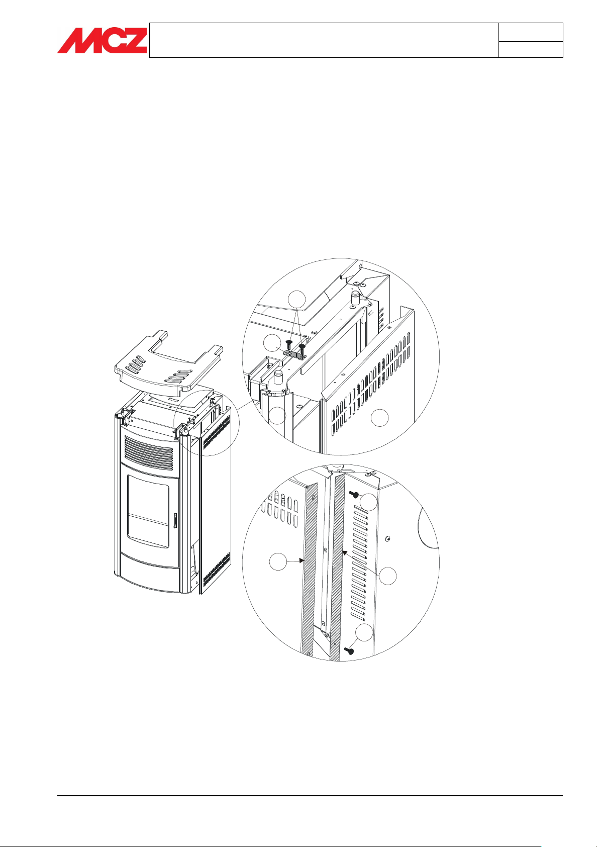
3.3.6. Assembly of sides on the MUSA stove
Remove the cast iron top, take the sides A (one for the right side and
one for the left) and insert them on the runners of the profile B paying
attention that the rear part of the side E (the one with a 90° bend)
overlaps with the sheet metal bend of the structure F and that the
lower part of the side enters in the plugs on the base.
Take the plate C provided and fix it with the two screws D, on the
upper part in correspondence to the structure and the side.
The rear side must be fixed to the stove's structure using the four
screws G provided.
When both steel sides A are assembled, replace the cast iron top.
Page 32
PELLET STOVES
Chapter 3
INSTALLATION AND USE MANUAL
page 32
Installation and assembly
Technical service - Rights reserved MCZ GROUP S.p.A. - Reproduction prohibited
IMPORTANT!
The connection of the stove to the plumbing system
must be made ONLY by specialized personnel who
are capable of carrying out installation properly, in
compliance with current standards in the country of
installation.
MCZ will not be held responsible for damage to
persons or things in the event of failed operation if
the aforementioned warning is not complied with.
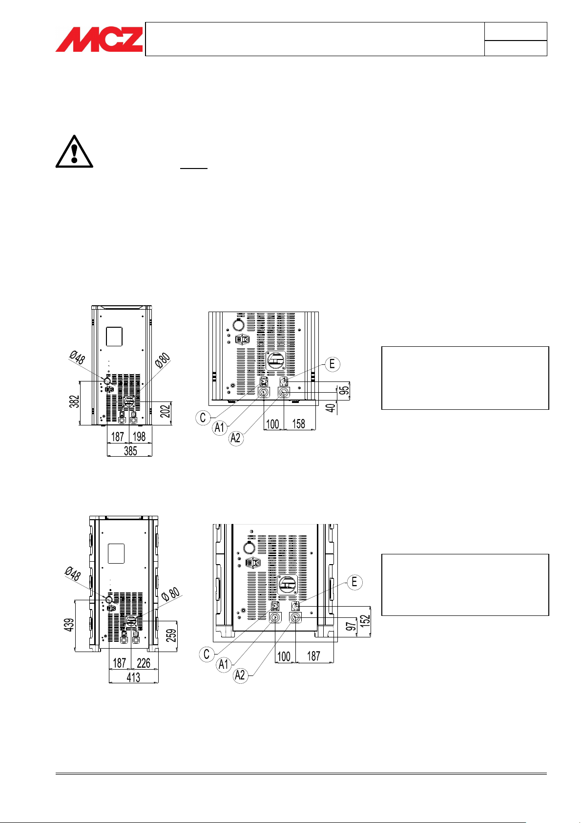
A1=Heating water delivery 3/4”M
A2=Heating water return 3/4”M
C=Safety valve 3 bar – 1/2”F
E=System emptying 1/2”F
A1=Heating water delivery 3/4”M
A2=Heating water return 3/4”M
C=Safety valve 3 bar – 1/2”F
E=System emptying 1/2”F
3.4. PLUMBING SYSTEM CONNECTION
CONNECTION DIAGRAM FOR EGO-STAR HYDRO STOVE
CONNECTION DIAGRAM FOR SUITE-CLUB HYDRO STOVE
Page 33
PELLET STOVES
Chapter 3
INSTALLATION AND USE MANUAL
page 33
Installation and assembly
Technical service - Rights reserved MCZ GROUP S.p.A. - Reproduction prohibited
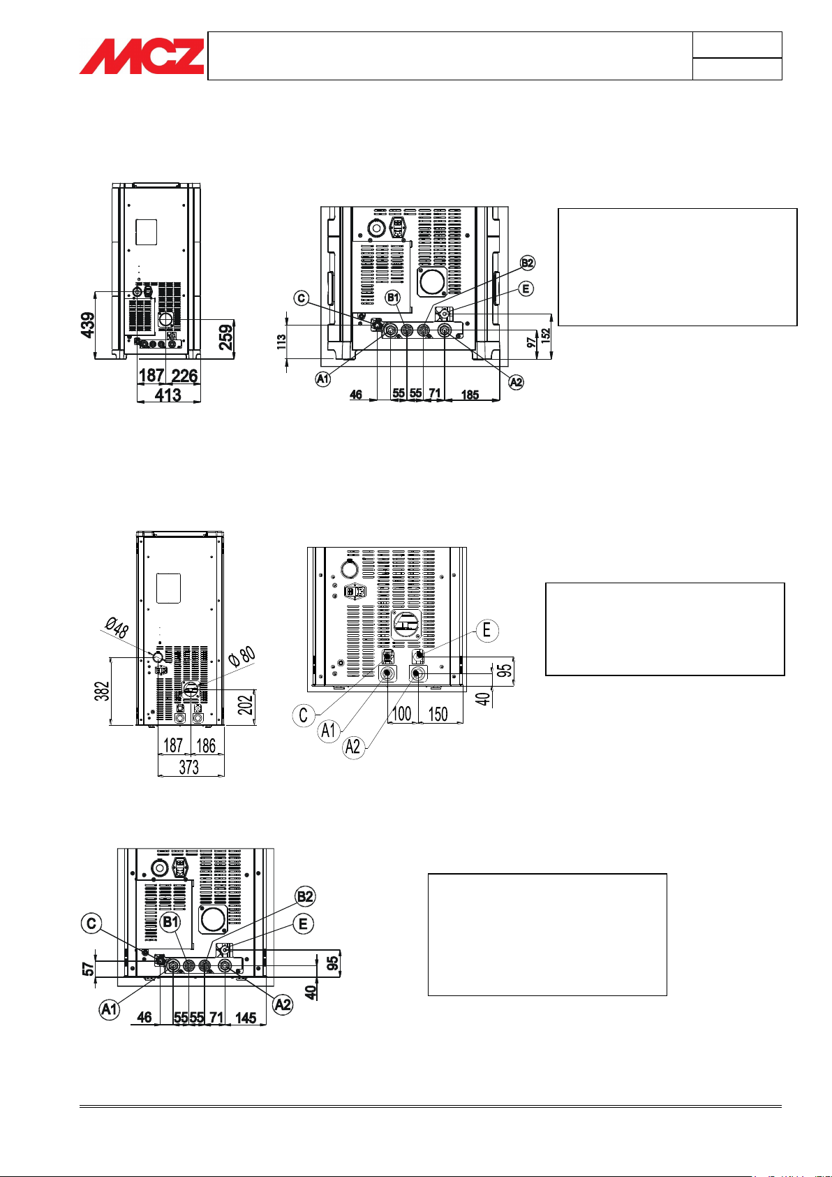
A1=Heating water delivery 3/4”M
A2=Heating water return 3/4”M
C=Safety valve 3 bar – 1/2”F
E=System emptying 1/2”F
A1= Heating water flow pipe 3/4”M
A2= Heating water return pipe 3/4”M
C= 3 bar safety shut off valve– 1/2”F
E= System emptying device 1/2”F
B1= Domestic water flow pipe
B2= Domestic water return pipe
A1= Heating water flow pipe 3/4”M
A2= Heating water return pipe 3/4”M
C= 3 bar safety shut off valve– 1/2”F
E= System emptying device 1/2”F
B1= Domestic water flow pipe
B2= Domestic water return pipe
CONNECTION DIAGRAM FOR THE SUITE-CLUB HYDRO STOVE EQUIPPED WITH KIT FOR DOMESTIC
HOT WATER PRODUCTION
CONNECTION DIAGRAM FOR MUSA HYDRO STOVE
CONNECTION DIAGRAM FOR THE MUSA HYDRO STOVE EQUIPPED WITH KIT FOR DOMESTIC HOT
WATER PRODUCTION
Page 34
PELLET STOVES
Chapter 3
INSTALLATION AND USE MANUAL
page 34
Installation and assembly
Technical service - Rights reserved MCZ GROUP S.p.A. - Reproduction prohibited
IMPORTANT
IT IS STRONGLY RECOMMENDED TO FLUSH THE
ENTIRE SYSTEM BEFORE CONNECTING IT IN ORDER
TO GET RID OF RESIDUES AND DEPOSITS.
Upstream from the stove, always install valves so as
to disconnect it from the plumbing system should it
be necessary to move it, or when it requires routine
and/or special maintenance.
Connect the stove using flexible hoses so that the
stove is not too strictly connected to the system, and
to allow slight movements.
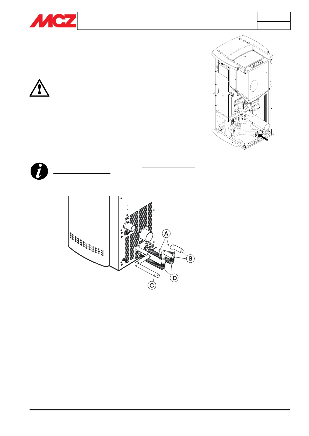
The pressure discharge valve (C) is always connected
to a water drain pipe. The pipe must be adequate to
support the water's high temperature and pressure.
A = TAP
B = DOMESTIC SYSTEM
C = PRESSURE DISCHARGE
D = FLEXIBLE PIPES
Pressure discharge valve (3 bar)
3.4.1. Connections to the system
Make the connections to the corresponding fittings shown in the
diagram on the previous page. Make sure the pipes are not placed
under tension or undersized.
Page 35
PELLET STOVES
Chapter 3
INSTALLATION AND USE MANUAL
page 35
Installation and assembly
Technical service - Rights reserved MCZ GROUP S.p.A. - Reproduction prohibited
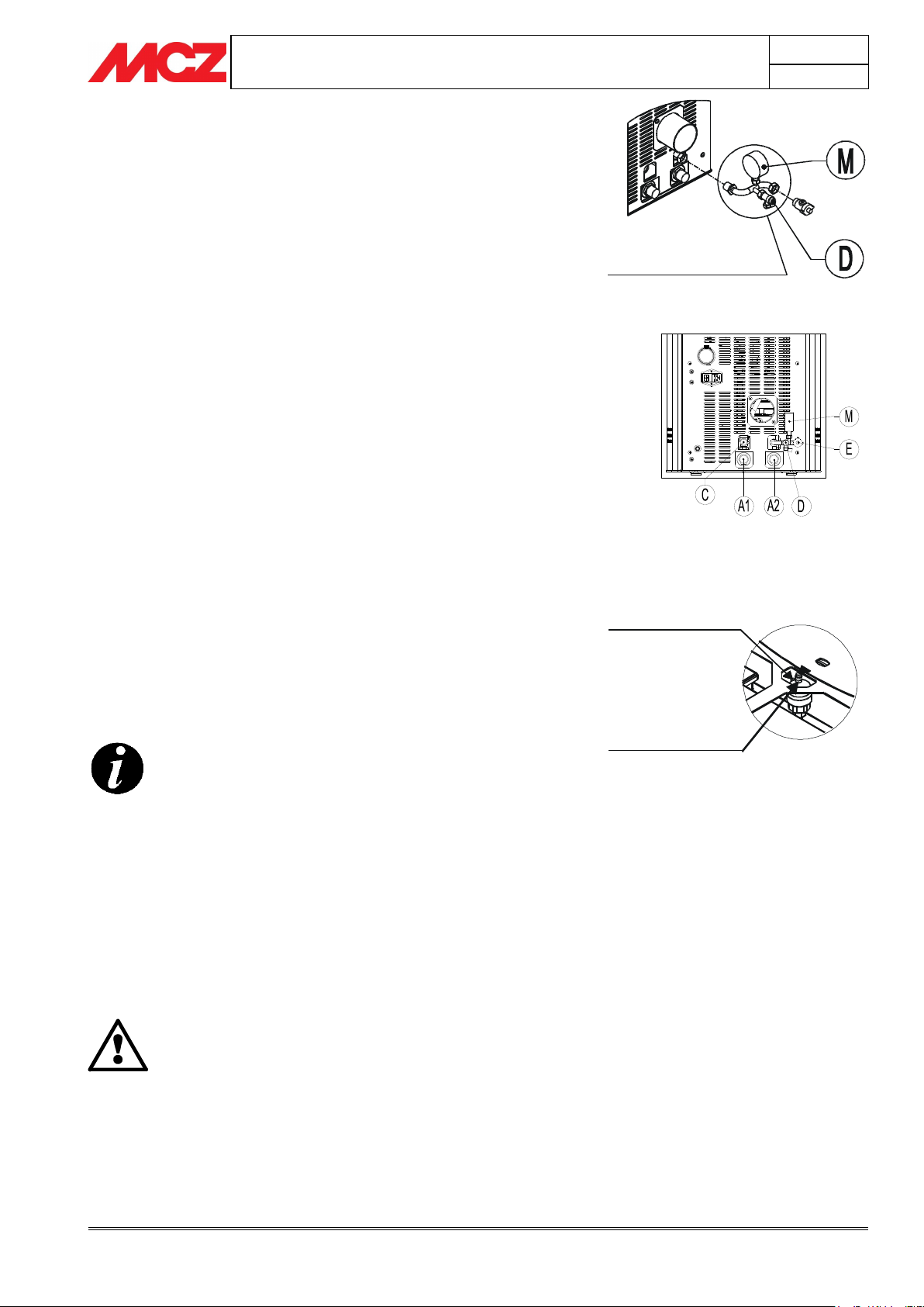
End piece with a
filling tap (D)
and pressure gauge (M)
(accessory)
Grey plug loosened
1 turn
Red plug blocked
Hardness of water circulating in the system, to prevent
problems of incrustation and limescale, especially in the
domestic water heat exchanger. (> 25° French)
Installation of a water softener (if water hardness
exceeds 25° French)
Filling the system with treated water (demineralised).
Possibly providing an anti-condensation circuit.
Installation of plumbing bumpers to prevent banging
along the fittings and pipes.
It should be remembered that incrustations
drastically reduce performance due to low thermal
conductivity.
Filling tap (D)
Pressure gauge (M)
Vent valve under the top
3.4.2. System filling
To fill the system, the stove can be equipped with an end piece
(optional)
system (if the
will be used). During this operation, any air in the system is released
from the automatic vent valve located under the top.
To ensure the valve vents correctly, it is advisable to loosen the grey
cap one turn and to keep the red cap blocked
The filling pressure of the system WHEN COLD must be
1 bar.
During operation, if the system pressure drops (due to evaporation of
dissolved gases in the water) to values lower than the minimum
indicated above, the user must use the filling tap to bring the pressure
back up to its normal pressure.
For proper operation of the stove WHEN HOT, the pressure in the
boiler must be1.5 bar.
To monitor system pressure, the end piece
equipped with a pressure gauge (M).
Upon completion of this operation, always close the tap.
with a non-return valve (D), for manual filling of the heating
optional
is not installed, the filling tap on the main boiler
(see figure)
(optional)
is
3.4.3. Water characteristics
The characteristics of the water used to fill the system are very
important to prevent the build-up of mineral salts and the formation of
incrustations along the pipes, in the boiler and in the heat exchangers.
Therefore, please GET YOUR PLUMBER'S ADVICE
CONCERNING:
If you have very extensive systems, with a large amount of water, or
which require frequent refilling, the installation of water softening
systems.
Page 36
PELLET STOVES
Chapter 3
INSTALLATION AND USE MANUAL
page 36
Installation and assembly
Technical service - Rights reserved MCZ GROUP S.p.A. - Reproduction prohibited
To ensure that the plate heat exchanger continues to
operate correctly over time, it is important that you
know the water hardness of your system to prevent
deposits from forming.
If the water in your home is very hard, you are
advised to install a softening system upstream (see
chapter 3.4.3)
You are advised to maintain the plate heat exchanger
annually to eliminate calcium sediments and mineral
salts or to replace heating plates with new ones. MCZ
supplies these replacement parts.
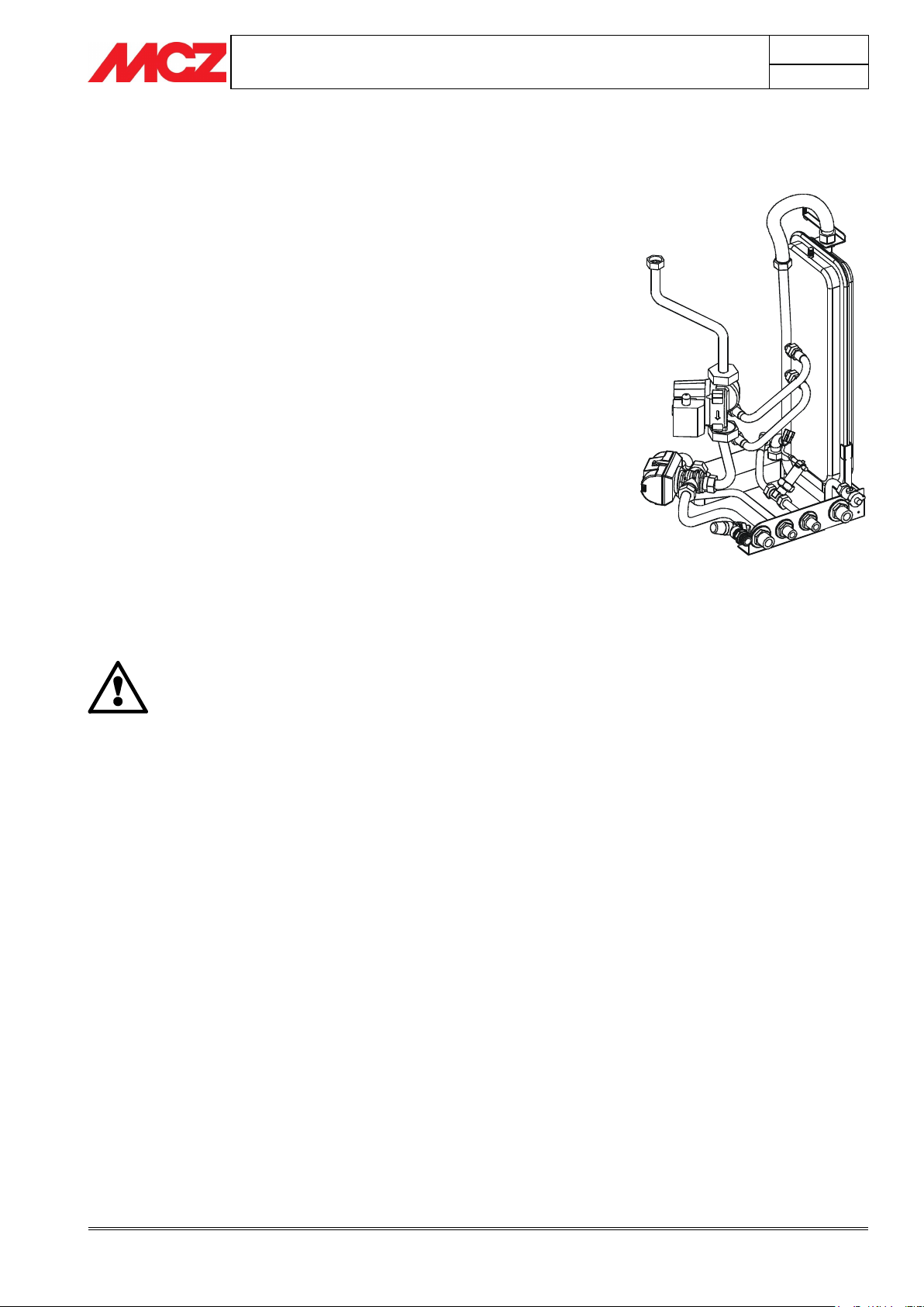
3.5. KIT FOR DOMESTIC HOT WATER PRODUCTION
(Optional) Only for Suite/Club/Musa stoves
SUITE – CLUB and MUSA stoves can also be equipped with a full kit for
the production of domestic hot water. This kit comprises:
A plate heat exchanger
A three-way diverter valve
Water flow switch
Pipes and unions for connection
The kit is designed to heat domestic water directly from the home
water supply system. MCZ supplies the kit ready-assembled.
When the tap is turned on and hot water is needed, the internal water
flow switch will send a signal to the diverter valve to channel the hot
water from the boiler (where it is stored) to the plate heat exchanger.
The temperature of the domestic water depends a great deal on the
temperature of the water inside the heating system. This can be
calculated to a good degree of accuracy by taking 10°-15°C away from
the value shown on the control panel of the stove (which is the
temperature of the water in the boiler).
If hot domestic water is needed while the stove is ‘Off’ or in ‘off ECOSTOP’ mode, the stove will automatically and immediately begin the
start-up process to heat the water inside the boiler, followed by the
domestic hot water.
Page 37
PELLET STOVES
Chapter 3
INSTALLATION AND USE MANUAL
page 37
Installation and assembly
Technical service - Rights reserved MCZ GROUP S.p.A. - Reproduction prohibited
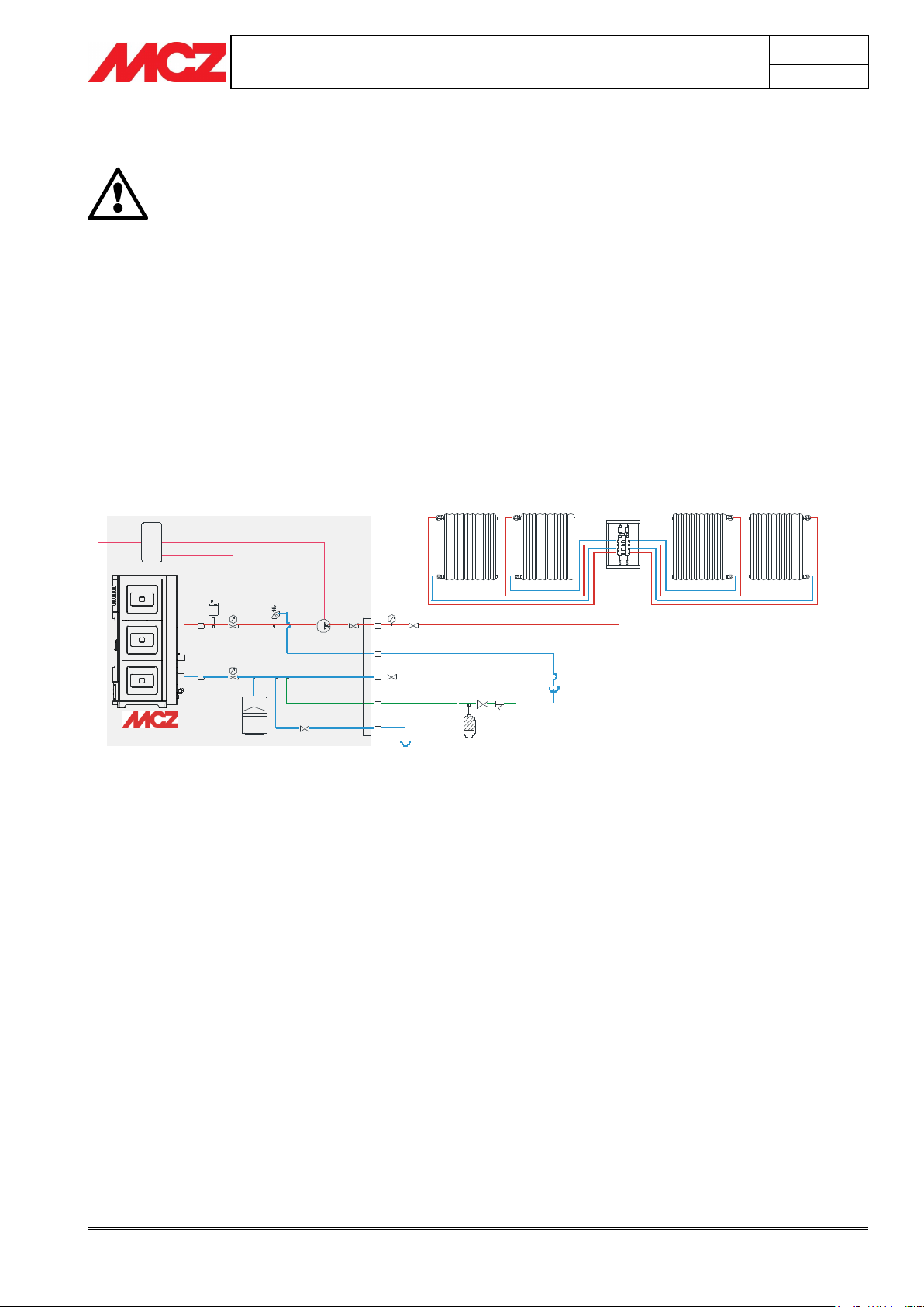
The following diagrams are to be used only as a
guideline. For proper connection, always follow the
notes for the plumbing and heating installer. The
plumbing system must meet local, regional or
national requirements. Installation and verification of
operation is to be performed only by specialized,
authorized personnel.
MCZ will not be held liable for non-compliance with
the provisions listed above.
S
T
VS
P
VE
V
Vsc
T
SE
230V 50HZ
RA RA RA RA
RP
Flt
A
V
V
M
SYSTEM DELIVERY
PRESSURE SAFETY DISCHARGE
SYSTEM RETURN
SYSTEM REFILL
SE Electronic card
S Automatic vent
M Pressure gauge
VS Vent valve, 3 bar
V Valve
P Pump
VD One-way valve
T Measurement of boiler temperature
VE Expansion tank, 1.5 bar of 6 l
W 3-way motorized valve
SC Plate heat exchanger
F Flow switch
C Methane gas boiler
B Boiler
BA Storage boiler
RA Radiators
PR Radiant panels
PS Solar panels
A Pounding absorber
RP Pressure reduction valve
Vsc Boiler/system discharge valve
Flt System filter
Add Softener
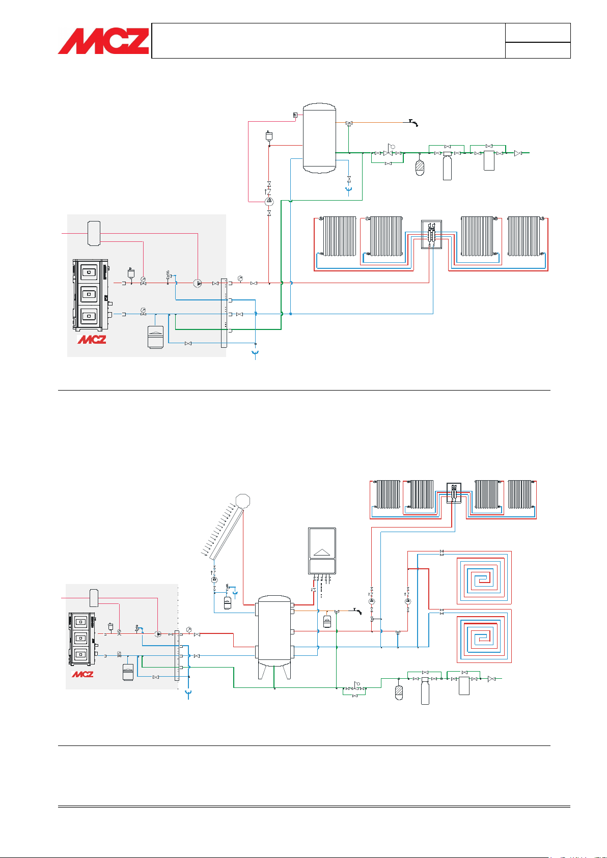
3.6. EXAMPLE INSTALLATION DIAGRAMS
3.6.1. Installation diagram for heating system without domestic hot water kit
(EGO/STAR/SUITE/CLUB/MUSA)
PERFORMANCE:
HEATING WITH STOVE
CONFIGURATION: STAR/EGO/SUITE/CLUB/MUSA WITH DOMESTIC HOT WATER KIT
SYSTEM OF SYSTEM WITH CLOSED TANK ONLY FOR HEATING BY MEANS OF RADIATORS
SIGNATURFORKLARING:
Page 38
PELLET STOVES
Chapter 3
INSTALLATION AND USE MANUAL
page 38
Installation and assembly
Technical service - Rights reserved MCZ GROUP S.p.A. - Reproduction prohibited
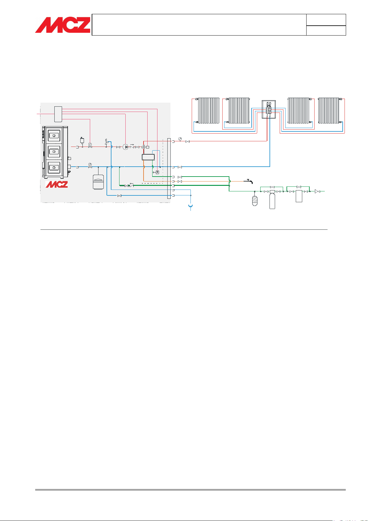
230V 50HZ
SE
S
T
VS
P
VE
V
V
VD
VD
V
T
SC
VV
R
PRESTAZIONI:
RISCALDAMENTO CON STUFA
RA RA RA RA
Vsc
Flt
Add
A
RP
V
V
V
M
PRODUZIONE DI ACQUA SANITARIA CON STUFA
Componenti in dotazione della stufa
MANDATA IMPIANTO
RITORNO IMPIANTO
INGRESSO ACQUA SANITARIA FREDDA
USCITA ACQUA SANITARIA CALDA
REINTEGRO IMPIANTO
SCARICO SICUREZZA PRESSIONE
CONFIGURAZIONE: SUITE/CLUB/MUSA CON KIT SANITARIO
SCHEMA IMPIANTO A VASO CHIUSO PER RISCALDAMENTO MEDIANTE RADIATORI O PRODUZIONE DI ACQUA CALDA SANITARIA
LEGENDA:
SE
S
M
VS
V
P
VD
T
VE
VV
SC
F
C
B
B A
RA
PR
PS
A
RP
Vsc
Flt
Add
Scheda elettronica
Sfiato automatico
Manometro
Valvola di sfiato 3 bar
Valvola
Pompa
Valvola unidirezionale
Misurazione temperatura caldaia
Vaso di espansione 1,5 bar da 6 lt
Valvola a 3 vie motorizzata
Scambiatore a piastre
Flussostato
Caldaia a gas metano
Bollitore
Bollitore ad accumulo
Radiatori
Pannelli radianti
Pannelli solari
Ammortizzatore colpi d’ariete
Valvola riduttrice di pre ssione
Valvola scarico impianto/caldaia
Filtro impianto
Addolcitore
3.6.2. Installation diagram for heating system with domestic hot water kit
(SUITE/CLUB/MUSA)
Page 39
PELLET STOVES
Chapter 3
INSTALLATION AND USE MANUAL
page 39
Installation and assembly
Technical service - Rights reserved MCZ GROUP S.p.A. - Reproduction prohibited
R
230V 50HZ
SE
S
VS
P
VE
T
Vsc
B
T
RA RA RA RA
Flt
Add
A
RP
V
V
M
V
SYSTEM DELIVERY
SYSTEM RETURN
COLD DOMESTIC
WATER INLET
HOT DOMESTIC WATER OUTLET
PRESSURE SAFETY
DISCARGE
SYSTEM REFILL
R
230V 50HZ
S
VS
P
VE
VT
T
C
PS
BA
PR
PR
SE
RA RA RA RA
Vsc
Flt
Add
A
RP
V
V
M
HOT DOMESTIC
WATER OUTLET
PRESSURE SAFETY
DISCHARGE
SYSTEM REFILL
SYSTEM DELIVERY
SYSTEM RETURN
COLD DOMESTIC
WATER INLET
SE Electronic card
S Automatic vent
M Pressure gauge
VS Vent valve, 3 bar
V Valve
P Pump
VD One-way valve
T Measurement of boiler temperature
VE Expansion tank, 1.5 bar of 6 l
W 3-way motorized valve
SC Plate heat exchanger
F Flow switch
C Methane gas boiler
B Boiler
BA Storage boiler
RA Radiators
PR Radiant panels
PS Solar panels
A Pounding absorber
RP Pressure reduction valve
Vsc Boiler/system discharge valve
Flt System filter
Add Softener
SE Electronic card
S Automatic vent
M Pressure gauge
VS Vent valve, 3 bar
V Valve
P Pump
VD One-way valve
T Measurement of boiler temperature
VE Expansion tank, 1.5 bar of 6 l
W 3-way motorized valve
SC Plate heat exchanger
F Flow switch
C Methane gas boiler
B Boiler
BA Storage boiler
RA Radiators
PR Radiant panels
PS Solar panels
A Pounding absorber
RP Pressure reduction valve
Vsc Boiler/system discharge valve
Flt System filter
Add Softener
3.6.3. Heating installation diagram in combination with a boiler
PERFORMANCE:
HEATING WITH STOVE
PRODUCTION OF DOMESTIC
HOT WATER WITH BOILER
CONFIGURATION: STAR/EGO/SUITE/CLUB/MUSA WITHOUT DOMESTIC HOT WATER KIT COMBINED WITH BOILER
HEATING WITH STORAGE SYSTEM PRODUCTION OF DOMESTIC HOT WATER WITH STORAGE SYSTEM
SIGNATURFORKLARING:
3.6.4. Heating installation in combination with a storage tank
PERFORMANCE:
HEATING WITH STORAGE SYSTEM
PRODUCTION OF DOMESTIC HOT
WATER WITH STORAGE SYSTEM
CONFIGURATION: STAR/EGO/SUITE/CLUB/MUSA WITHOUT DOMESTIC HOT WATER KIT COMBINED WITH STORAGE SYSTEM WITH BOILER AND SOLAR PANELS
SYSTEM DIAGRAM WITH CLOSED TANK FOR HEATING WITH RADIATORS OR RADIANT PANELS AND FOR THE PRODUCTION OF DOMESTIC HOT WATER
SIGNATURFORKLARING:
Page 40
PELLET STOVES
Chapter 3
INSTALLATION AND USE MANUAL
page 40
Installation and assembly
Technical service - Rights reserved MCZ GROUP S.p.A. - Reproduction prohibited
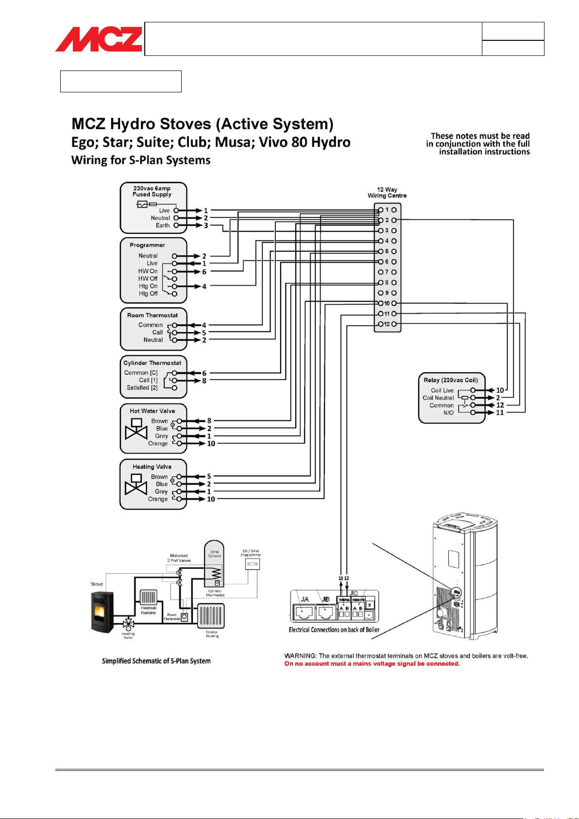
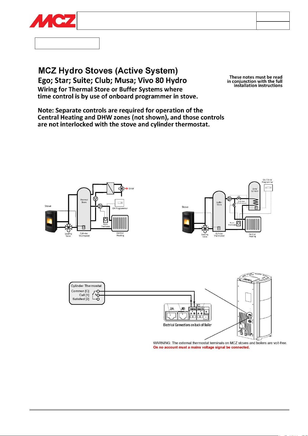
ONLY FOR UK
Page 41
PELLET STOVES
Chapter 3
INSTALLATION AND USE MANUAL
page 41
Installation and assembly
Technical service - Rights reserved MCZ GROUP S.p.A. - Reproduction prohibited
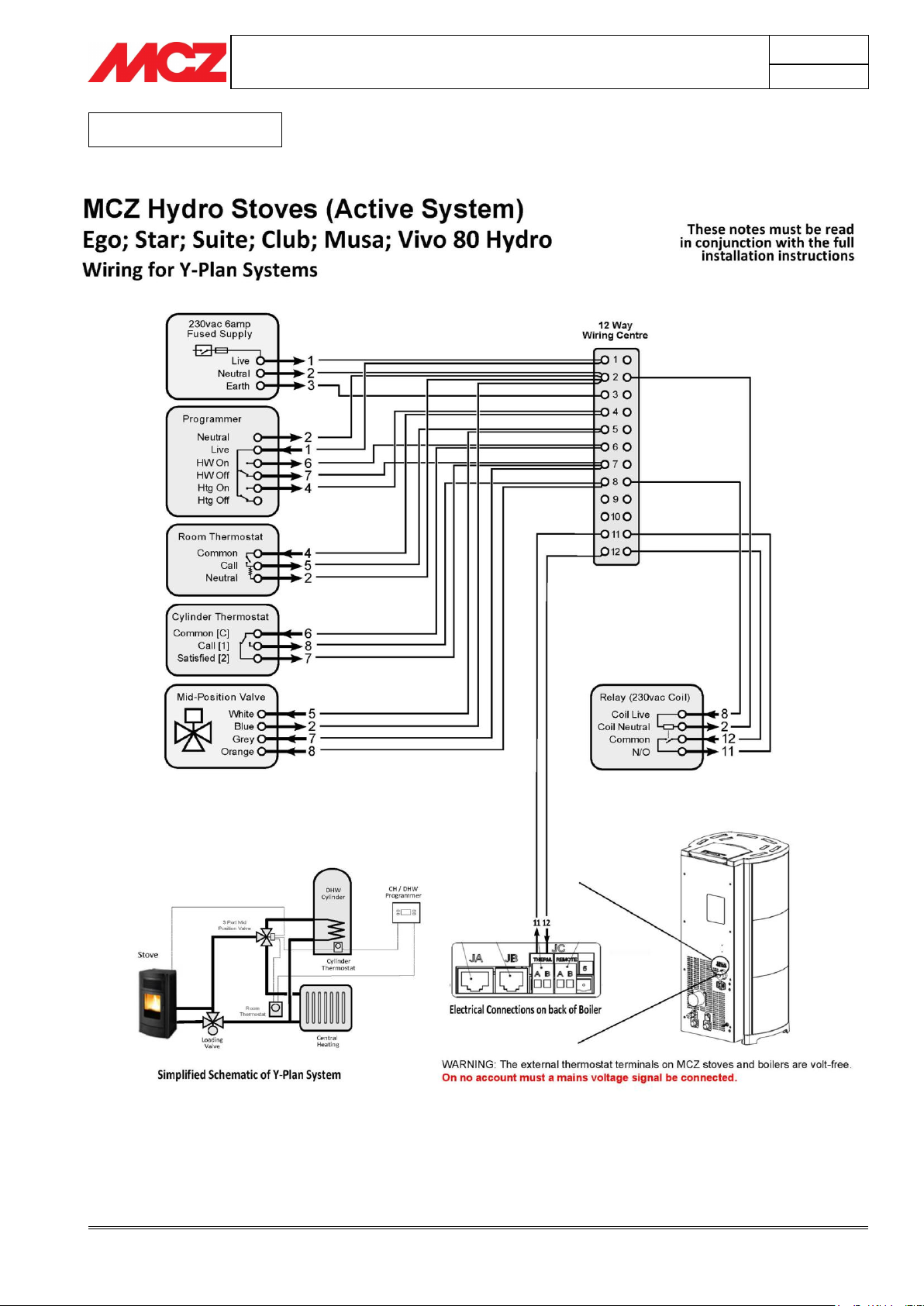
ONLY FOR UK
Page 42
PELLET STOVES
Chapter 3
INSTALLATION AND USE MANUAL
page 42
Installation and assembly
Technical service - Rights reserved MCZ GROUP S.p.A. - Reproduction prohibited
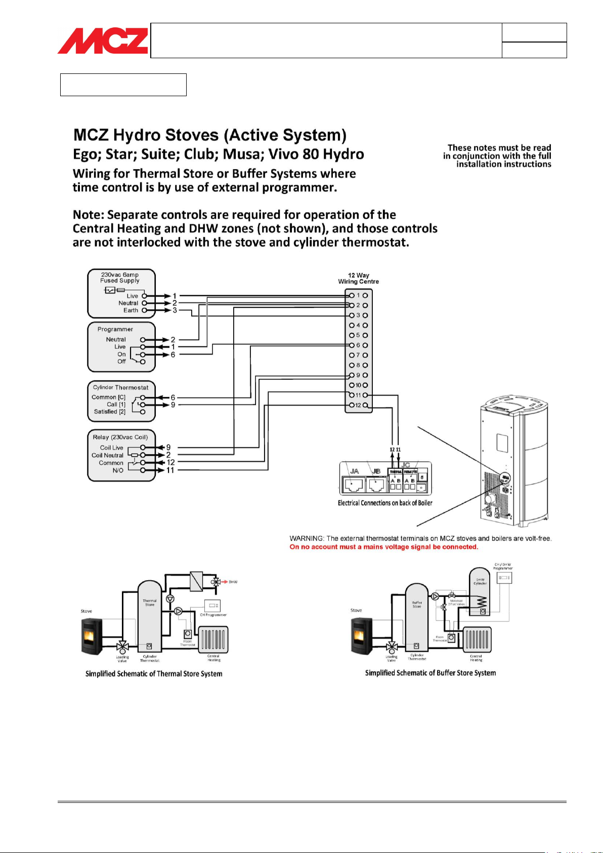
ONLY FOR UK
Page 43
PELLET STOVES
Chapter 3
INSTALLATION AND USE MANUAL
page 43
Installation and assembly
Technical service - Rights reserved MCZ GROUP S.p.A. - Reproduction prohibited
ONLY FOR UK
Page 44
PELLET STOVES
Chapter 3
INSTALLATION AND USE MANUAL
page 44
Installation and assembly
Technical service - Rights reserved MCZ GROUP S.p.A. - Reproduction prohibited
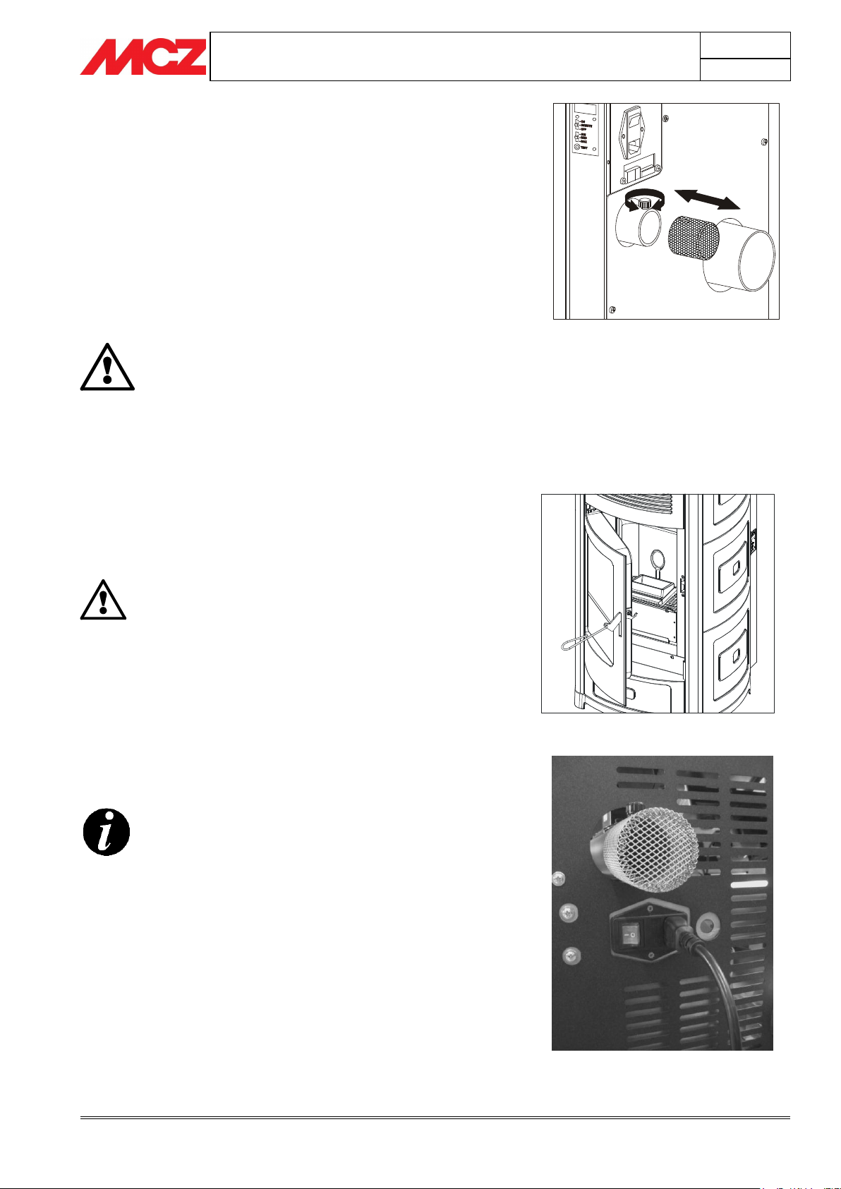
ATTENTION!
Never operate the stove without the air filter. Please
ensure this is serviced each year to prevent any
blockage of air flow to the appliance. MCZ shall not be
held liable for damage to internal components if this
instruction is not followed.
WARNING!
In order for the stove to operate correctly, it is
essential that the door be closed completely.
If you do not intend to use the stove, it is advisable to
keep it switched off.
Electrical connection of the stove
Installation/removal of air filter
Opening/closing the door
3.7. INSTALLATION OF AIR FILTER
Before placing the stove near the wall for connection to the flue
pipe and to the electrical mains, install the air filter provided
with the stove.
The cylindrical filter is composed of a metallic net and is already
installed on the stove
The filter must be inserted on the air inlet pipe Ø 5 cm.
To remove it, slightly loosen the screw with the knob on the air inlet,
insert the filter matching it with the filter groove with the screw of the
knob and then secure it by tightening the knob.
3.8. OPENING/CLOSING THE DOOR
The door is opened with the hook on the door, which must be lifted
using the cool hand provided.
3.9. MAKING THE ELECTRICAL CONNECTIONS
Connect the supply cable first at the rear of the stove and then to an
electrical outlet on the wall.
The main switch located on the rear of the stove should be switched on
only when you want to light the stove.
Page 45

Page 46

Page 47

Page 48

8901505700
Rev 0
01/2015
MCZ GROUP S.p.A.
Via La Croce n°2
33074 Vigonovo di Fontanafredda (PN) – ITALY
Telephone: 0434/599599 r.a.
Fax: 0434/599598
Internet: www.mcz.it
e-mail: [email protected]
 Loading...