

Page 1
EN
Contents
ANTHEA –MYRIA-LUNA-QUASAR-NADIR-PULSAR-SIRIO-ZENIT-VENUS-
COMETA-ALPHA-ORION – MODULO LEGNA
Technical service - MCZ S.p.A. all rights reserved - Reproduction prohibited
Page 2
EN 13240:2001, AC:2003,
AC:2006, A2:2004,
Sicherheitsabstände (Seitlich):
Sicherheitsabstände (Hinten):
Veiligheidsafstand (achteraan):
Stäub:
Stofdeeltjes:
Distanze di sicurezza (retro):
Distances de sécurité (postérieures):
Rendimento :
Potenza nominale:
Puissance nominale:
Heizleistung:
Nominaal vermogen:
Mittlere Abgastemperatur:
Temperatuur rook:
Veiligheidsafstand (zijdelings):
Particolato:
Poussieres:
Emissione CO (al 13% O
Emissions CO (Bez.13% O2):
Mittlere CO- Emission (Bez.13% O
CO-emissie (bij 13% O2):
Rendement :
Energieeffizenz:
Rendement:
Temperatura fumi:
Température des fumées:
Distanze di sicurezza (lato):
Distances de sécurité (laterales):
EN 13240:2001, AC:2003,
AC:2006, A2:2004,
Temperatura fumi:
Température des fumées:
Mittlere Abgastemperatur:
Veiligheidsafstand (zijdelings):
Veiligheidsafstand (achteraan):
Distanze di sicurezza (lato):
Distances de sécurité (laterales):
Sicherheitsabstände (Seitlich):
Sicherheitsabstände (Hinten):
Temperatuur rook:
Distanze di sicurezza (retro):
Distances de sécurité (postérieures):
Rendimento :
Rendement :
Energieeffizenz:
Rendement:
Particolato:
Poussieres:
Stäub:
Stofdeeltjes:
Emissione CO (al 13% O
Emissions CO (Bez.13% O2):
Mittlere CO- Emission (Bez.13% O
CO-emissie (bij 13% O2):
Puissance nominale:
Heizleistung:
Nominaal vermogen:
Potenza nominale:
EN 13240:2001, AC:2003,
AC:2006, A2:2004,
Distances de sécurité (laterales):
Sicherheitsabstände (Seitlich):
Veiligheidsafstand (zijdelings):
Distances de sécurité (postérieures):
Sicherheitsabstände (Hinten):
Veiligheidsafstand (achteraan):
Distanze di sicurezza (lato):
Poussieres:
Stäub:
Stofdeeltjes:
Distanze di sicurezza (retro):
Température des fumées:
Mittlere Abgastemperatur:
Temperatuur rook:
Particolato:
CO-emissie (bij 13% O2):
Nominaal vermogen:
Emissione CO (al 13% O
Emissions CO (Bez.13% O2):
Mittlere CO- Emission (Bez.13% O
Rendimento :
Rendement:
Temperatura fumi:
Rendement :
Energieeffizenz:
Puissance nominale:
Heizleistung:
Potenza nominale:
EN 13240:2001, AC:2003,
AC:2006, A2:2004,
Particolato:
Poussieres:
Stäub:
Stofdeeltjes:
Temperatura fumi:
Température des fumées:
Veiligheidsafstand (zijdelings):
Distanze di sicurezza (retro):
Distances de sécurité (postérieures):
Sicherheitsabstände (Hinten):
Veiligheidsafstand (achteraan):
Distanze di sicurezza (lato):
Distances de sécurité (laterales):
Sicherheitsabstände (Seitlich):
Heizleistung:
Nominaal vermogen:
Emissione CO (al 13% O
Emissions CO (Bez.13% O2):
Mittlere CO- Emission (Bez.13% O
CO-emissie (bij 13% O2):
Mittlere Abgastemperatur:
Temperatuur rook:
Potenza nominale:
Rendement:
Rendimento :
Rendement :
Energieeffizenz:
Puissance nominale:
EN 132 40:2001, AC:2003,
AC:2006, A2:20 04,
Distances de sécurité (postérieures):
Veiligheidsafstand (zijdelings):
Sicherheitsabstände (Hinten):
Distanze di sicurezza (lato):
Distances de sécurité (laterales):
Emissione CO (al 13% O
Emissions CO (Bez.13% O2):
Stofdeeltjes:
Puissance nominale:
Heizleistung:
CO-emissie (bij 13% O2):
Rendimento :
Energieeffizenz:
Rendement:
(1)
(2)
Température des fumées:
Mittlere Abgastemperatur:
Particolato:
MCZ GROUP S.p.A. - Via La Croce 8, I - 33074 Vigonovo di Fontanafredda (PN) Italy.
BImSchV
Art. 15a B-VG
07
VKF AEAI
Regensburger BStV erfüllt
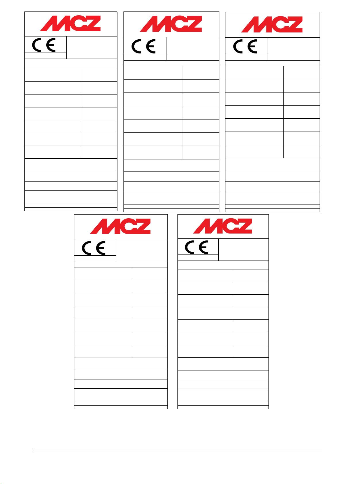
ANTHEA (1) / MYRIA (2) / LUNA (3)
Potenza nominale:
Nominaal vermogen:
Mittlere CO- Emission (Bez.13% O
Rendement :
Temperatura fumi:
Temperatuur rook:
Poussieres:
Stäub:
Distanze di sicurezza (retro):
Veiligheidsafstand (achteraan):
Sicherheitsabstände (Seitlich):
Prodotto conforme all'installazione in canna multipla. Produit conforme à l'installation
dans un conduit multiple. Gerät ist für eine Mehrfachbelegung des Schornsteins
geeignet.Product conform de installatie in een multi-rookkanaal.
Apparecchio a funzionamento intermittente. Produit à fonctionnement intermittent.
Zeitbrand Feuerstätte. Apparatuur voor intermitterende werking.
Utilizzare solo con combustibile adatto. A utiliser seulement avec un combustible
conforme. Nur zugelassennen Brennstoff verwenden.Gebruik enkel gepaste pellets.
Leggere e seguire le istruzioni! Lire et suivre les
instructions! Bedienungsanleitung lesen und
beachten!Lees en respecteer de aanwijzingen!
2):
Made in Italy
2):
COD: 89 070080
12,0 kW
11,0 kW
10,0 kW
(3)
0,11%
87,6%
300 °C
49 mg/Nm3 (13% O2)
31 mg/MJ
300 mm
500 mm
MCZ GROUP S.p.A. - Via La Croce 8, I - 33074 Vigonovo di Fontanafredda (PN) Italy.
BImSchV
Art. 15a B-VG
07
VKF AEAI
Regensburger BStV erfüllt
MODULO LEGNA
12 kW
2):
2):
0,11%
87,6%
300 °C
55 mg/Nm3 (13% O2)
33 mg/MJ
300 mm
500 mm
Prodotto conforme all'installazione in canna multipla. Produit conforme à l'installation
dans un conduit multiple. Gerät ist für eine Mehrfachbelegung des Schornsteins
geeignet.Product conform de installatie in een multi-rookkanaal.
Apparecchio a funzionamento intermittente. Produit à fonctionnement intermittent.
Zeitbrand Feuerstätte. Apparatuur voor intermitterende werking.
Utilizzare solo con combustibile adatto. A utiliser seulement avec un combustible
conforme. Nur zugelassennen Brennstoff verwenden.Gebruik enkel gepaste pellets.
Leggere e seguire le istruzioni! Lire et suivre les
instructions! Bedienungsanleitung lesen und
beachten!Lees en respecteer de aanwijzingen!
Made in Italy
COD: 89070082
MCZ GROUP S.p.A. - Via La Croce 8, I - 33074 Vigonovo di Fontanafredda (PN) Italy.
07
BImSchV
Art. 15a B-VG
VKF AEAI
Regensburger Münchener
BStV erfüllt
QUASAR
7,9 kW
2):
2):
0,11%
78,3%
270 °C
14 mg/Nm3 (13% O2)
9 mg/MJ
300 mm
500 mm
Prodotto conforme all'installazione in canna multipla. Produit conforme à l'installation
dans un conduit multiple. Gerät ist für eine Mehrfachbelegung des Schornsteins
geeignet.Product conform de installatie in een multi-rookkanaal.
Apparecchio a funzionamento intermittente. Produit à fonctionnement intermittent.
Zeitbrand Feuerstätte. Apparatuur voor intermitterende werking.
Utilizzare solo con combustibile adatto. A utiliser seulement avec un combustible
conforme. Nur zugelassennen Brennstoff verwenden.Gebruik enkel gepaste pellets.
Leggere e seguire le istruzioni! Lire et suivre les
instructions! Bedienungsanleitung lesen und
beachten!Lees en respecteer de aanwijzingen!
Made in Italy
COD: 89070079
MCZ GROUP S.p.A. - Via La Croce 8, I - 33074 Vigonovo di Fontanafredda (PN) Italy.
07
BImSchV
Art. 15a B-VG
VKF AEAI
Regensburger Münchener
BStV erfüllt
NADIR / PULSAR
8 kW
2):
2):
0,09%
85,0%
240 °C
67 mg/Nm3 (13% O2)
42 mg/MJ
300 mm
500 mm
Prodotto conforme all'installazione in canna multipla. Produit conforme à l'installation
dans un conduit multiple. Gerät ist für eine Mehrfachbelegung des Schornsteins
geeignet.Product conform de installatie in een multi-rookkanaal.
Apparecchio a funzionamento intermittente. Produit à fonctionnement intermittent.
Zeitbrand Feuerstätte. Apparatuur voor intermitterende werking.
Utilizzare solo con combustibile adatto. A utiliser seulement avec un combustible
conforme. Nur zugelassennen Brennstoff verwenden.Gebruik enkel gepaste pellets.
Leggere e seguire le istruzioni! Lire et suivre les
instructions! Bedienungsanleitung lesen und
beachten!Lees en respecteer de aanwijzingen!
Made in Italy
COD: 8901027300
MCZ GROUP S.p.A. - Via La Croce 8, I - 33074 Vigonovo di Fontanafredda (PN) Italy.
07
SIRIO / ZENIT / VENUS /
COMETA / ALPHA / ORION
BImSchV
Art. 15a B-VG
VKF AEAI
Regensburger Münchener
BStV erfüllt
7,4 kW
2):
2):
0,10%
84,6%
250 °C
28 mg/Nm3 (13% O2)
19 mg/MJ
300 mm
500 mm
Prodotto conforme all'installazione in canna multipla. Produit conforme à l'installation
dans un conduit multiple. Gerät ist für eine Mehrfachbelegung des Schornsteins
geeignet.Product conform de installatie in een multi-rookkanaal.
Apparecchio a funzionamento intermittente. Produit à fonctionnement intermittent.
Zeitbrand Feuerstätte. Apparatuur voor intermitterende w erking.
Utilizzare solo con combustibile adatto. A utiliser seulement avec un combustible
conforme. Nur zugelassennen Brennstoff verwenden.Gebruik enkel gepaste pellets.
Leggere e seguire le istruzioni! Lire et suivre les
instructions! Bedienungsanleitung lesen und
beachten!Lees en respecteer de aanwijzingen!
Made in Italy
COD: 89070081
Contents
Technical service - MCZ S.p.A. all rights reserved - Reproduction prohibited
Page 3

INTRODUCTION
Revisions to the publication ...................................................................................................................... 4
Manual preservation. ............................................................................................................................... 4
How to read the manual .......................................................................................................................... 4
1. WARNINGS AND WARRANTY CONDITIONS ...................................................................................... 5
1.1. SAFETY WARNINGS .......................................................................................................................... 5
1.2. OPERATING WARNINGS .................................................................................................................... 5
1.3. WARRANTY CONDITIONS ................................................................................................................. 5
1.3.1. Restrictions ................................................................................................................................ 6
1.3.2. Exclusions .................................................................................................................................. 6
2. NOTIONS FOR INSTALLATION ACCORDING TO UNI 10683 ............................................................. 7
2.1. OPERATING AREA ............................................................................................................................. 7
2.2. PRECAUTIONS .................................................................................................................................. 7
2.3. EXTERNAL AIR OUTLET .................................................................................................................... 8
2.4. CHIMNEY FLUE CONNECTIONS .......................................................................................................... 9
2.5. CHIMNEY FLUE ................................................................................................................................. 9
2.5.1. Examples of chimney flues ........................................................................................................ 10
2.6. CHIMENYPOT ................................................................................................................................. 11
3. DIMENSIONS AND TECHNICAL SPECIFICATIONS .......................................................................... 12
3.1. PRESTIGE LINE .............................................................................................................................. 12
3.2. DESIGN LINE .................................................................................................................................. 15
3.3. MODULO LINE ................................................................................................................................ 18
4. INSTALLATION AND ASSEMBLY ...................................................................................................... 19
4.1. PREPARATION AND UNPACKING...................................................................................................... 19
4.2. POSITIONING ................................................................................................................................. 19
4.3. ASSEMBLY AND FEET ADJUSTMENT ................................................................................................. 20
4.4. CERAMICS ASSEMBLY ..................................................................................................................... 20
4.5. FRAME ASSEMBLY (WOOD MODULE) ............................................................................................... 20
5. OPERATION ..................................................................................................................................... 21
5.1. PRE-LIGHTING WARNINGS .............................................................................................................. 21
5.2. FUEL .............................................................................................................................................. 21
5.3. STOVE USE .................................................................................................................................... 22
5.3.1. LOADING THE FUEL ................................................................................................................. 22
5.3.2. CONTROL OF COMBUSTION ..................................................................................................... 22
5.3.2.1.
5.3.2.2.
5.3.2.3.
5.3.3. FIRST LIGHTING ...................................................................................................................... 23
5.4. EMERGENCY TREATMENT ............................................................................................................... 25
6. MAINTENANCE AND CLEANING ...................................................................................................... 26
6.1. CLEANING TO BE PERFORMED BY THE USER ................................................................................... 26
6.1.1. Cleaning the glass .................................................................................................................... 26
6.1.2. Cleaning upper calorite deflectors ............................................................................................. 26
6.1.3. Cleaning out the ashes ............................................................................................................. 26
6.1.4. Cleaning of stainless steel and satin-finish surfaces .................................................................... 26
6.1.5. Cleaning of painted parts .......................................................................................................... 27
6.1.6. Cleaning and characteristics of marble and steatite cladding. ...................................................... 27
6.1.7. Cleaning flue pipe .................................................................................................................... 27
6.2. CLEANING BY SPECIALISED PERSONNEL ......................................................................................... 27
Model adjustments: LUNA – MYRIA – ANTHEA – MODULO ................................................... 23
Model adjustments: QUASAR – ORION – SIRIO – VENUS – COMETA – ZENIT – ALPHA .......... 23
Model adjustments: PULSAR – NADIR ................................................................................. 23
Contents
Technical service - MCZ S.p.A. all rights reserved - Reproduction prohibited
Page 4
INSTALLATION AND USE MANUAL
INTRODUCTION
Dear customer,
We would like to thank you for your choice of MCZ
products. We are sure that, with use, you will
appreciate the quality of an attentively designed and
tested product. Our goal is to combine technology
with easy use and, above all, safety.
For best stove operations and to fully enjoy the
heat and sense of well being it will spread
throughout your home, we suggest you
carefully read this booklet before use; please
contact your dealer for full assistance in
resolving any doubts or problems.
Congratulations on your choice and remember, the
stove MUST NEVER be used by children who should
always be kept at a safe distance from your stove!
Revisions to the publication
Introduction
page
4
These symbols signal specific messages in this
booklet
WARNING:
This warning symbol found in various
points in this manual indicates that the
user should carefully read and understand
the message to which it refers since
neglect to follow these instructions
could cause serious stove damages or
injury to the user.
INFORMATION:
This symbol intends to emphasise
important information for good stove
operations. Failure to observe these
instructions could jeopardise product use
and operations may be unsatisfactory
In order to improve the product, the Manufacturer
reserves the right to modify and update this
publication without prior notice.
Reproduction, even partial, of this manual without the
Manufacturer's authorisation is prohibited.
Manual preservation.
• Please keep and store this manual handy.
• If this manual should be lost or destroyed, or if it
is in poor condition, ask for a copy from your
retailer or directly from the manufacturer,
providing product identification data.
How to read the manual
• An essential item or one that requires specific
attention is published in “bold”.
•
“Script”
illustrations or check other manual sections that
may provide more in-depth explanations.
• NOTE: the “NOTE” provides the reader with
additional information on the subject.
is used to invite the user to review the
Introduction
Technical service - MCZ S.p.A. all rights reserved - Reproduction prohibited
Page 5

INSTALLATION AND USE MANUAL
1. WARNINGS AND WARRANTY
CONDITIONS
1.1. SAFETY WARNINGS
• Only qualified or authorised personnel should
install, check and maintain the stove.
• Install the stove according to correct local,
regional or state regulations.
• For correct stove and accessory use and to
prevent accidents, always follow the instructions
in this booklet.
• Before beginning any operation, the user, or
whoever is operating the stove, must have read
and understood the entire contents of this
instruction booklet.
• The stove must only be used as intended. Any
other use is considered improper and therefore
hazardous.
• Do not use the stove as a ladder or support surface.
• Do not dry clothing on the stove. Any drying
racks or similar devices must be kept a certain
distance from the stove. Fire hazard.
• Assess the static conditions of the surface that will hold
the stove's weight and adequately insulate if made of
flammable material (i.e. wood, carpet, plastic).
• Avoid installation in rooms with B type gas
devices, hoods with or with exhaust, heat pumps,
collective ventilation conduits.
• Avoid installing several operating chimney flues in
the same room or the vicinity of a stair well and
make sure equipment whose simultaneous use
would cause a depression in adjacent and
communicating rooms.
• The user is fully liable for improper product use,
releasing MCX from any civil or penal liabilities.
• Any tampering or unauthorised and non original
part replacement may be hazardous to the user
and releases MCZ from any civil or penal liability.
• Some parts of the stove surface are very hot
(door, handle, glass, smoke stack, etc.).
Therefore, avoid direct contact with these parts
unless wearing protective clothing or specific
means such as, for example, heat protective
gloves or "cold" activation devices.
• Explain these hazards to the elderly, the
handicapped and especially to all children,
keeping them far from the stove when operating.
• Incorrect installation or poor maintenance (non
conform with that indicated in this manual) may
cause damages to persons, animals or property.
MCZ is not civilly or criminally liable in these
cases.
Chapter 1
page
5
1.2. OPERATING WARNINGS
• Turn off the stove in the event of faults or poor
operations.
• Install the stove in rooms that meet fire safety
standards and equipped with all the air intake and
smoke exhaust services.
• Do not start fires with flammable materials.
INFORMATION:
• For any problem, please contact your dealer or
MCZ qualified and authorised personnel and
always request original spare parts for repairs.
• Only use the fuel stated by MCZ.
• Check and periodically clean the smoke exhaust
stack as foreseen by current regulations in the
country of installation.
• Carefully preserve this instruction manual since it
should be kept with the stove for its entire
working life. If the stove is sold or transferred to
another user, make sure the manual accompanies
the product.
• If lost, please request a copy from your dealer or
from MCZ.
1.3. WARRANTY CONDITIONS
MCZ guarantees the product, except for the
elements subject to normal wear listed below, for
two years from the date of purchase proven by a
document that indicates the dealer's name and date
of sale, if the completed warranty certificate was
returned within 8 days and if the product was installed
and inspected by a specialised installation technician
and according to the detailed instructions indicated in
the instruction manual supplied with the product.
The warranty includes the free replacement or repair
of parts recognised as factory defective.
Warnings and warranty conditions
Technical service - MCZ S.p.A. all rights reserved - Reproduction prohibited
Page 6
INSTALLATION AND USE MANUAL
1.3.1. Restrictions
The warranty does not cover parts subject to normal
wear such as: gaskets, glass, and all removable
furnace parts.
Replaced parts will be guaranteed for the remaining
warranty period from the date of product purchase.
Specifically, glass is guaranteed
from the moment the MCZ
installation technician certifies its
integrity when installation is
completed.
1.3.2. Exclusions
The warranty does not cover any part that may
be defective due to negligence or careless use,
incorrect maintenance, installation non
compliant with that specified by MCZ (see
relevant chapters in this manual).
MCZ is not liable for any damages, direct or indirect,
to persons, animals or property consequent to neglect
to observe all the instructions indicated in this manual
and especially concerning the installation, use and
maintenance warnings.
In the event of product inefficiency, please contact
your dealer and/or area importer.
Damages caused by transport and handling are not
covered by the warranty.
Exclusively refer to the supplied manual for product
installation and use.
The warranty is null and void in the event of damages
due to tampering, weather, natural calamities,
lightening, fire, defective electrical and hydraulic
systems and the lack or incorrect maintenance as per
the manufacturer's instructions.
SERVICE REQUESTS
Service requests must be addressed
to the dealer who shall forward the
request to MCZ technical assistance.
MCZ is not liable in the event the
product and any other accessory is
improperly used or modified without
authorisation.
Only original MCZ spare parts must be
used for all replacements.
Chapter 1
page
6
Warnings and warranty conditions
Technical service - MCZ S.p.A. all rights reserved - Reproduction prohibited
Page 7
INSTALLATION AND USE MANUAL
2. NOTIONS FOR INSTALLATION ACCORDING TO UNI 10683
2.1. OPERATING AREA
For good operations and good heat distribution, the stove should be
positioned in a place where the air required for combustion can flow (at
least 60 m3/h must be available) according to installation standards and
current regulations in the country of installation.
The room volume must not be less than 60 m3.
Air must enter through permanent apertures on the walls (near the
stove) that open outdoors with a minimum section of 150 cm2.
These apertures (air vents) must be made so as not to be obstructed in
any way.
Air can also be taken from adjacent rooms as long as these are
equipped with outdoor air vents and not bedrooms or bathrooms or
rooms where fire hazards do not exist such as garages, wood sheds,
flammable material warehouses, strictly observing that stated in current
regulations.
• Stoves may not be installed in bedrooms,
bathrooms and where another heating device is
installed without autonomous air flow (chimney,
stove, etc.).
• Placing the stove in explosive environments is
prohibited.
• The floor of the room where the stove is installed
must be adequately dimensions to support its
weight.
• In the event of wood floors, install a protective
covering in accordance with current regulations
in the country of installation.
• If walls are not flammable, install the stove at
least 5 cm. from the walls.
• The stove could cause overheating and damages
to plaster (yellowing, cracking, etc.) if
excessively close to the wall.
Chapter 2
page
7
2.2. PRECAUTIONS
The stove must be installed in a suitable surface that permits routine
opening and maintenance operations.
The room must be:
• set for room operating conditions
• equipped with an adequate smoke exhaust system
• equipped with outdoor ventilation
Theoretic notions for installation
Technical service - MCZ S.p.A. all rights reserved - Reproduction prohibited
Page 8
INSTALLATION AND USE MANUAL
IMPORTANT!
• The stove must be installed and assembled by
qualified personnel.
• The stove must be connected to a chimney flue or
other vertical smoke stack that can discharge
smoke at the highest point of the house.
• The stove must be connected to the internal or
external chimney flue or smoke stack, according
to current regulations.
• Smoke is generated from burning wood and,
therefore, may dirty adjacent or nearby walls.
• Before installing the stove, drill a hole for the
external air outlet.
2.3. EXTERNAL AIR OUTLET
The room where the stove is installed must have at least as much air as
requested by normal device combustions and by room ventilation. They
may occur through permanent apertures in the room walls that lead
directly outdoors or ventilated rooms according to UNI 10683 REV.
For this purpose, drill a hole with minimum 150 cm² free section near
the stove (15 cm diameter or a 10x15cm rectangle), protected by an
indoor and outdoor grill.
The air intake must also:
directly communicate with the installation room
• be protected by a grill, made of metallic anti-insect mesh or a
suitable protection as long as it does not reduce the minimum
section.
• be installed so as to avoid obstruction
• in the event of conduits, up to 3.5 ml, increase the section by
about 5% while increased by 15% for larger measurements.
Remember that the ventilation grill always have a cm2 useful
section on one side. When selecting the grill and hole
dimension, make sure the useful grill section is greater than
or equal to the section required by MCZ for product
operations.
Chapter 2
page
8
Connecting the air outlet directly to the stove is not
mandatory but the abovementioned section must guarantee
about 50 m³/h of air. See regulation UNI10683 REV.
IMPORTANT!
Air flow may also be obtained from a room adjacent
to the installation room as long as this flow is free
through permanent apertures that directly
communicate with the outdoors; avoid air outlets
connecting with heating units, garages, kitchens or
bathrooms.
Theoretic notions for installation
Technical service - MCZ S.p.A. all rights reserved - Reproduction prohibited
Page 9
MAX 2 mt.
3 - 5 %
INSTALLATION AND USE MANUAL
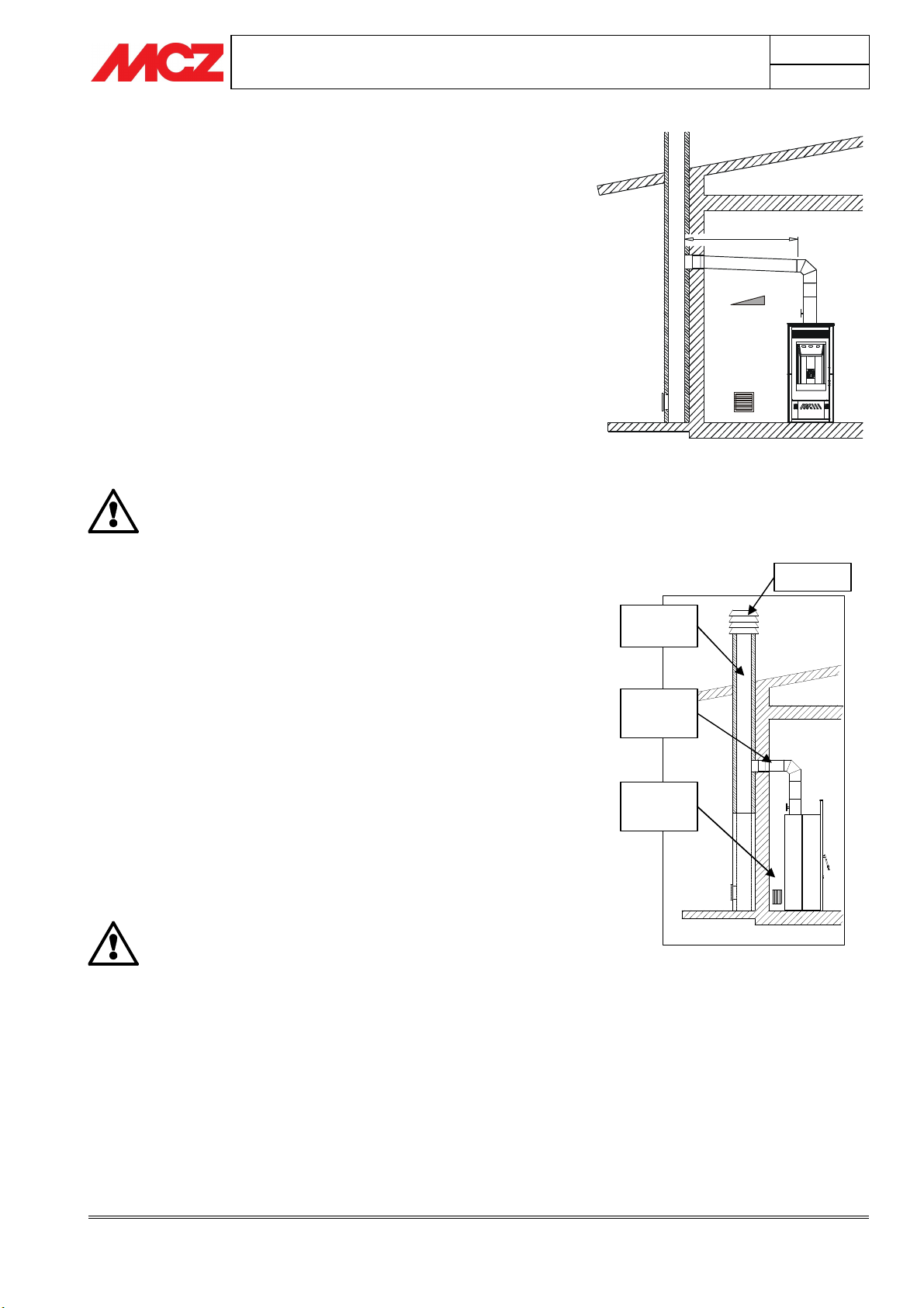
2.4. CHIMNEY FLUE CONNECTIONS
Connections to the chimney flue is important and should be conducted
with care and attention. Stoves have top or rear smoke exhausts.
The smoke exhaust pipe must be assembled to guarantee seals during
product operations in depression and avoid the formation and transport
of condensation to the stove.
Any manual draft adjustment devices inserted in the pipe must not
hermetically close the internal conduit section. These gates must be
equipped with a mechanism that prevents the full rotation of the valve
in the closed position. The minimum safety opening surface must be
3% of the passage section and not less than 10 cm². If the smoke
conduit has a horizontal segment, this must have a minimum upward
gradient of 3-5% (3-5 cm per meter).
The tilted horizontal part must not be longer than 2 ml.
The use of flexible and cement fibre pipes is
prohibited. The smoke stack must not cross rooms
where the installation of combustion devices is
prohibited. The use of pipes in counter-slope is
prohibited.
2.5. CHIMNEY FLUE
Chapter 2
page
9
Example of a connection to the chimney flue
Cowl
Flue pipe
The chimney flue is a fundamental element in discharging smoke and
therefore must have the following requisites:
• It must be waterproof and thermally insulated.
• It must be made with heat resistant materials, resistant to
combustion products and any condensation.
• It must have a vertical slope with axis deviations not over 45°
and without narrowing.
• It must meet the requisites indicated in the technical table for
the internal chimney section and height.
• It must preferably have a circular interior section.
• If pre-existent and previously operative, it must be clean.
The chimney flue is of primary importance for the
correct operations and safety of your stove.
Smoke
connection
Air outlet
external
Illustration of a correctly constructed
chimney flue with a chamber and sealed
door for solid combustion product collection
and discharge at the foot of the external
ascending segment.
Theoretic notions for installation
Technical service - MCZ S.p.A. all rights reserved - Reproduction prohibited
Page 10
INSTALLATION AND USE MANUAL
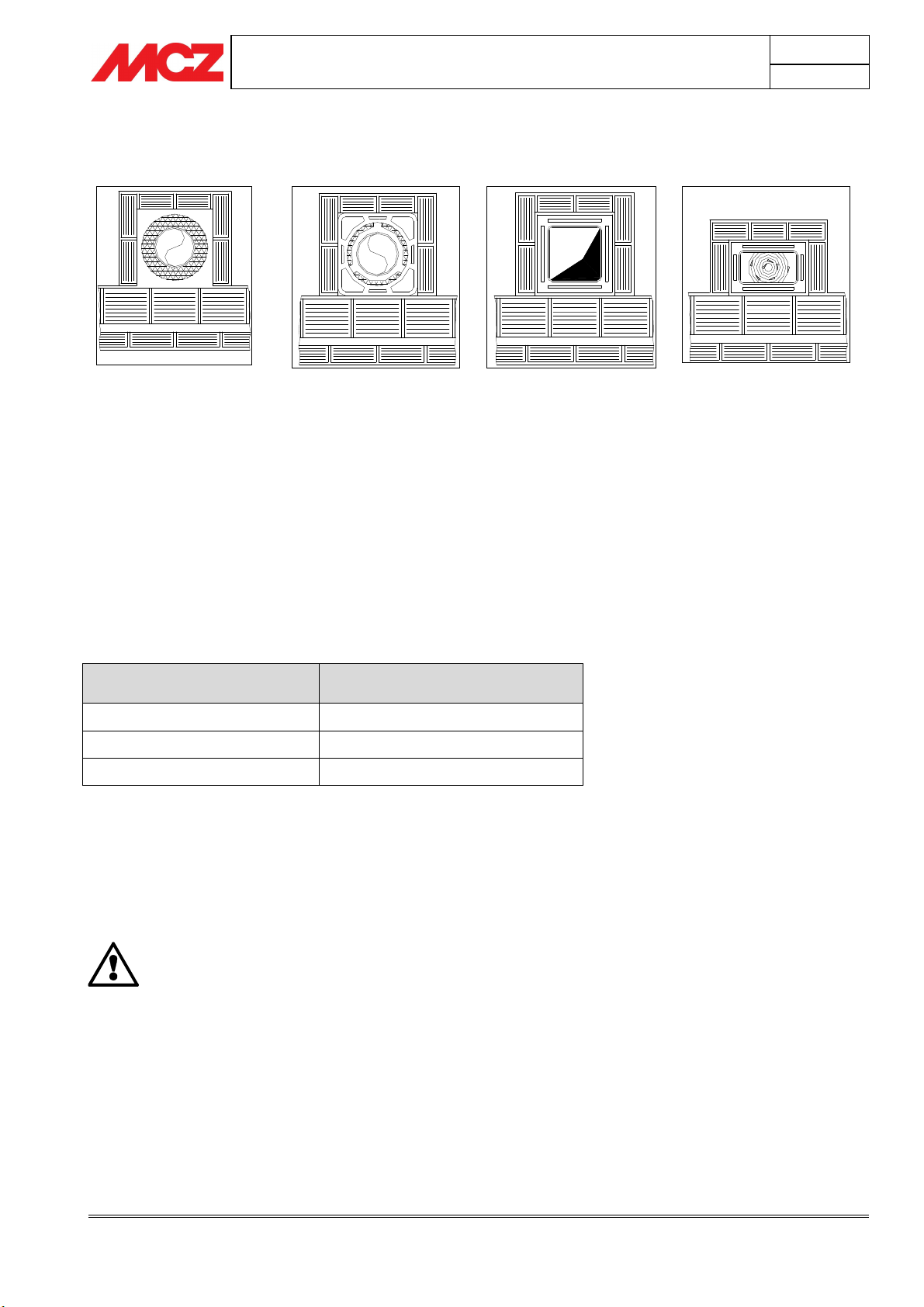
2.5.1. Examples of chimney flues
Chapter 2
page
10
AISI 304 stainless steel chimney
flue with dual chamber insulated
with ceramic wool or equivalent
resistant to 400°C.
EXCELLENT
Refractory chimney flue with
dual insulated chamber and
external concrete sleeve and
lightweight clay type
honeycomb material. GOOD
Traditional square section clay
chimney flue with insulating
hollow inserts.
AVERAGE
Square or rectangular section chimney flues must have rounded internal
corners with radius not less than 20mm. For the rectangular section,
the ratio between internal dimensions must be ≤1.5.
The recommended section for a chimney flue according to its length is
listed in the table below:
Height (m) Section (cm²)
Up to 5 mt (20x30 cm or ∅ 22 cm)
From 5 to 7 mt (20x20 cm or ∅ 20 cm)
Over 7 mt (18x18 cm or ∅ 18 cm)
N.B. Too small or too large a section reduces draught and insulation.
For special sections or section or travel variations, functional smoke
exhaust inspections must be conducted as per UNI 9615.
The smoke conduit should be equipped with a solid material collection
chamber at the mouth of the smoke conduit to be easily opened with an
airtight door.
IMPORTANT!
In the event of doubt on your chimney flue
operations or that its dimensions are different from
those recommended, we highly suggest an
authorised MCZ technician inspect and measure
chimney flue performance (micro-gauge
measurements)
MCZ s.p.a. is not liable for poor stove operations if
attributable to the use of a poorly dimensioned or
non conform installation of the chimney flue.
Avoid chimney flues with
internal rectangular sections
whose larger side is double the
smaller such as 20x40 or
15x30.
POOR
Theoretic notions for installation
Technical service - MCZ S.p.A. all rights reserved - Reproduction prohibited
Page 11
UPPER FLOOR OR
SOLID COMBUSTION
NO
INSTALLATION AND USE MANUAL
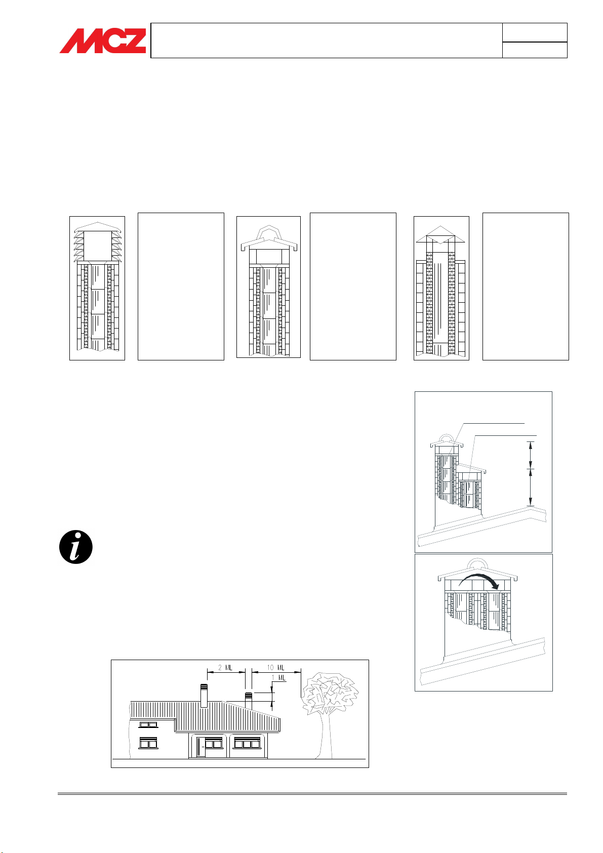
2.6. CHIMENYPOT
If underestimated, it is a terminal impediment to correct "chimney
system" operations.
Chimney flue draught is also a function of its chimneypot.
Therefore, if hand made, its four exhaust sections must correspond to
the more than twice the internal section of the chimney flue.
Having to exceed the peak of the roof, the chimneypot will be
exposed to wind, therefore an industrial type is recommended.
Industrial
chimneypot with
overlapping
prefabricated
elements.
Permits excellent
smoke exhaust.
Traditional hand
made chimneypot.
The right exhaust
section must be at
least twice the
internal section of
the chimney flue,
2.5 times is ideal.
Chapter 2
page
11
Steel chimneypot for
chimney flue with
internal smoke
deflector cone.
Permits excellent
smoke exhaust.
Chimneypots must meet the following requisites:
• They must have an internal section equal to that of the
chimney.
• They must have a useful output section not less that double
that of the internal section of the chimney flue.
• They must be built to prevent rain, snow and any foreign
object penetration in the chimney flue.
• They most be installed to guarantee excellent smoke
dispersion and out of the reflux are where counter-pressure
formation is favoured.
For paired chimney flues, the chimneypot for solid
combustion and the one for the upper floor must be at
least 50cm higher than the other to avoid pressure
transfers between paired flues.
The chimneypot must not have obstacles within 10 mt
such as walls, waterbeds and trees. Otherwise, raise it
at least 1 mt over the obstacle and, in the event of
other nearby chimneypots, keep them at least 2 mt
away and, in any case, the chimneypot must exceed
the peak of the roof by at least 1mt.
LOWER FLOOR
t
m
5
,
0
t
m
1
YES
Theoretic notions for installation
Technical service - MCZ S.p.A. all rights reserved - Reproduction prohibited
Page 12
1
0
0
1
640
620
5
9
4
1
1
5
0
640
620
5
9
4
INSTALLATION AND USE MANUAL
3. DIMENSIONS AND TECHNICAL SPECIFICATIONS
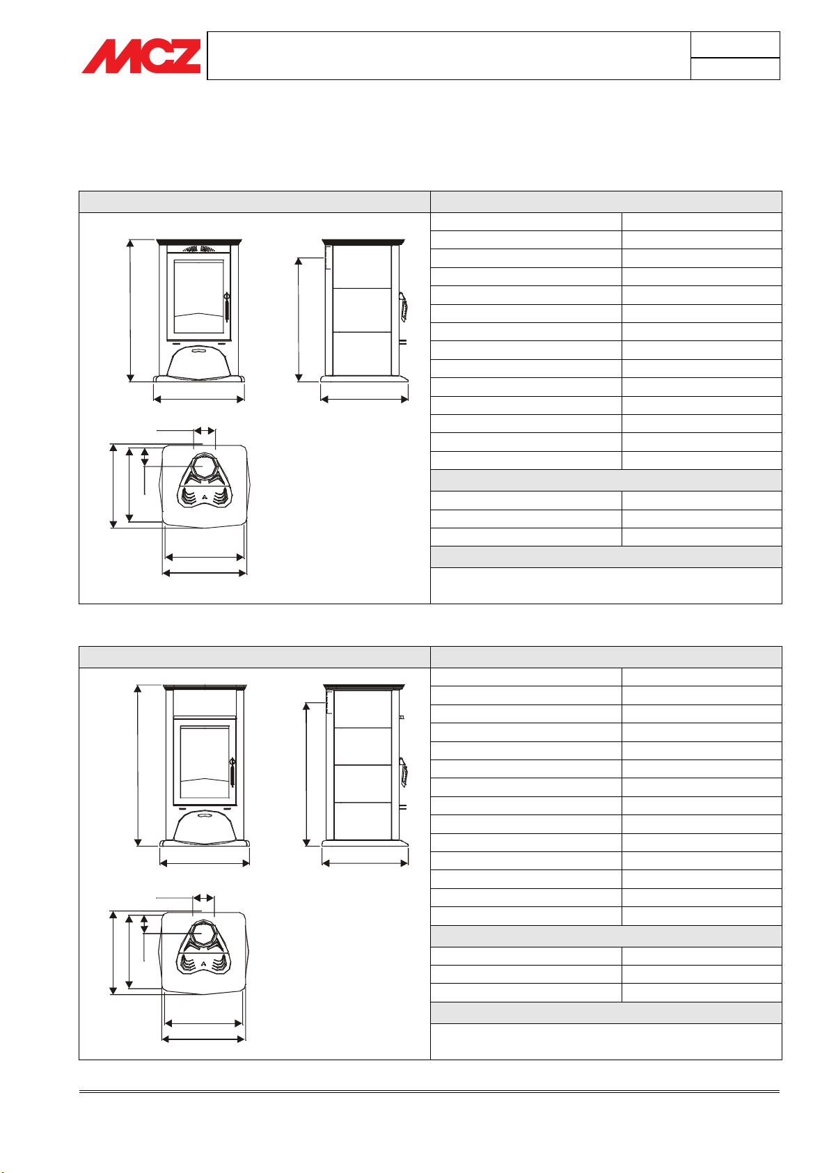
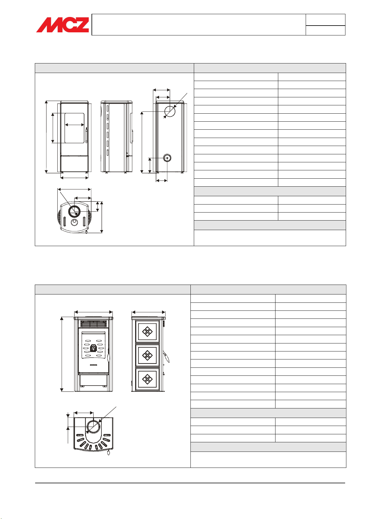
3.1. PRESTIGE LINE
LUNA Technical specifications
Fuel type Wood - Chips
Hourly consumption 2,6 kg/h – 1,8 kg/h
Maximum thermal power kW 10 Kcal 8600
Minimum thermal power kW 4,5/ Kcal 3870
Efficiency 87,6%
2
7
8
Ø150
0
0
6
2
1
5
556
594
MYRIA Technical specifications
1
2
0
1
Ø150
0
0
6
2
1
5
556
594
Heatable volume * 215/40 - 246/35 - 287/30
Minimum draught 12 Pa / 0,12 mbar
Smoke temperature 300 °C
Smoke outlet Ø 15 cm
Furnace dimensions 42,5 x 40 - h 43.5
Net weight Kg 250
External combustion air outlet cm² 150
CO2 emission in smoke (13 %O2) 0,11 %
Massive smoke capacity 10,8 g/s
Flue pipe
Up to 5 mt 20x30 cm Ø22
Between 5 and 7 mt. 20x20 cm Ø20
Over 7 mt 18x18 cm Ø18
Note
A stove is an intermittent combustion device
* Data may vary according to the fuel used
Fuel type Wood - Chips
Hourly consumption 2,9 kg/h – 2,0 kg/h
Maximum thermal power kW 11 Kcal 9460
Minimum thermal power kW 4,5/ Kcal 3870
Efficiency 87,6%
Heatable volume * 237/40 - 270/35 - 315/30
Minimum draught 12 Pa / 0,12 mbar
Smoke temperature 300 °C
Smoke outlet Ø 15 cm
Furnace dimensions 42,5 x 40 - h 43.5
Net weight Kg 250
External combustion air outlet cm² 150
CO2 emission in smoke (13 %O2) 0,11 %
Massive smoke capacity 11,0 g/s
Flue pipe
Up to 5 mt 20x30 cm Ø22
Between 5 and 7 mt. 20x20 cm Ø20
Over 7 mt 18x18 cm Ø18
Note
A stove is an intermittent combustion device
* Data may vary according to the fuel used
Chapter 3
page
12
Technical features and technical specifications
Technical service - MCZ S.p.A. all rights reserved - Reproduction prohibited
Page 13
5
9
4
1
2
4
4
8
0
INSTALLATION AND USE MANUAL
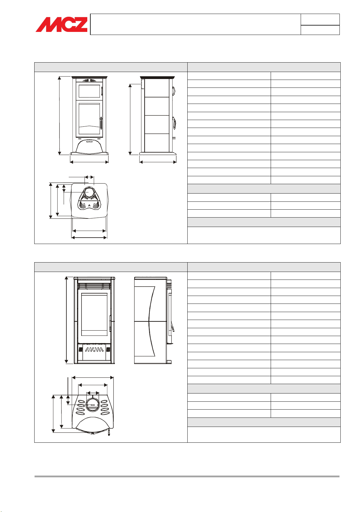
ANTHEA Technical specifications
Fuel type Wood - Chips
Hourly consumption 3.1 kg/h – 2.2 kg/h
Maximum thermal power kW 12 Kcal 10320
Minimum thermal power kW 4.5 Kcal 3870
6
0
3
1
6
7
1
1
620620
Ø150
0
0
6
2
1
5
556
594
Efficiency 87,6%
Heatable volume * 258/40 - 295/35 - 344/30
Minimum draught 12 Pa / 0.12 mbar
Smoke temperature 300 °C
Smoke outlet Ø 15 cm
Furnace dimensions 42.5 x 40 - h 43.5
Net weight Kg 250
External combustion air outlet cm² 150
CO2 emission in smoke (13 %O2) 0,11 %
Massive smoke capacity 11.2 g/s
Flue pipe
Up to 5 mt 20x30 cm Ø22
Between 5 and 7 mt. 20x20 cm Ø20
Over 7 mt 18x18 cm Ø18
Note
A stove is an intermittent combustion device
* Data may vary according to the fuel used
QUASAR Ceramics Technical specifications
Fuel type Wood - Chips
Hourly consumption 2.3 kg/h – 1.6 kg/h
Maximum thermal power kW 7.9 Kcal 6,794
Minimum thermal power kW 3.9 Kcal 3354
Efficiency 78,3 %
Heatable volume * 170/40 - 194/35 - 226/30
1
524
3
2
1
5
2
4
320
Ø150
Minimum draught 12 Pa / 0.12 mbar
Smoke temperature 270 °C
Smoke outlet Ø 15 cm
Furnace dimensions 33 x 32.5 - h 40
Net weight Kg 180
External combustion air outlet cm² 150
CO2 emission in smoke (13 %O2) 0,11 %
Massive smoke capacity 9 g/s
Flue pipe
Up to 5 mt 20x30 cm Ø22
Between 5 and 7 mt. 20x20 cm Ø20
Over 7 mt 18x18 cm Ø18
Note
A stove is an intermittent combustion device
* Data may vary according to the fuel used
Chapter 3
page
13
Technical features and technical specifications
Technical service - MCZ S.p.A. all rights reserved - Reproduction prohibited
Page 14
4
9
0
1
1
1
5
174
274
214
Ø
1
5
0
INSTALLATION AND USE MANUAL
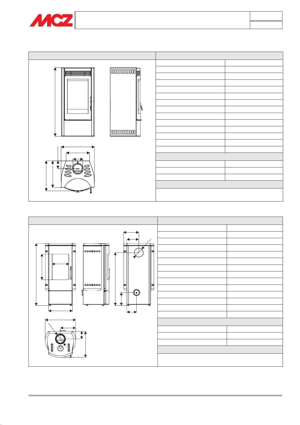
QUASAR Steel Technical specifications
Fuel type Wood - Chips
Hourly consumption 2.3 kg/h – 1.6 kg/h
Maximum thermal power kW 7.9 Kcal 6,794
Minimum thermal power kW 3.9 Kcal 3354
Efficiency 78,3 %
0
1
1
1
524
3
2
1
5
2
4
320
Ø150
Heatable volume * 170/40 - 194/35 - 226/30
Minimum draught 12 Pa / 0.12 mbar
Smoke temperature 270 °C
Smoke outlet Ø 15 cm
Furnace dimensions 33 x 32.5 - h 40
Net weight Kg 175
External combustion air outlet cm² 150
CO2 emission in smoke (13 %O2) 0,11 %
Massive smoke capacity 9 g/s
Flue pipe
Up to 5 mt 20x30 cm Ø22
Between 5 and 7 mt. 20x20 cm Ø20
Over 7 mt 18x18 cm Ø18
Note
A stove is an intermittent combustion device
* Data may vary according to the fuel used
PULSAR Technical specifications
Fuel type Wood - Chips
Hourly consumption 2.3 kg/h – 1.5 kg/h
Maximum thermal power kW 8 Kcal 6880
Minimum thermal power kW 3.9 Kcal 3354
Efficiency 85 %
0
6
4
299
1
5
9
3
3
2
428
548
Ø
1
274
5
0
7
3
1
8
6
4
Heatable volume * 172/40 - 197/35 - 229/30
Minimum draught 12 Pa / 0.12 mbar
Smoke temperature 240 °C
Smoke outlet Ø 15 cm
Furnace dimensions 29 x 29.5 - h 30
Net weight Kg 140
External combustion air outlet cm² 150
CO2 emission in smoke (13 %O2) 0,09 %
Massive smoke capacity 8.8 g/s
Flue pipe
Up to 5 mt 20x30 cm Ø22
Between 5 and 7 mt. 20x20 cm Ø20
Over 7 mt 18x18 cm Ø18
Note
A stove is an intermittent combustion device
* Data may vary according to the fuel used
Chapter 3
page
14
Technical features and technical specifications
Technical service - MCZ S.p.A. all rights reserved - Reproduction prohibited
Page 15
1
1
1
5
260
0
1
0
2
0
540
462
INSTALLATION AND USE MANUAL
NADIR Technical specifications
Fuel type Wood - Chips
Hourly consumption 2.3 kg/h – 1.5 kg/h
5
214
299
0
6
4
1
5
9
3
3
2
428
520
Ø
1
260
5
0
6
5
1
7
8
4
174
Maximum thermal power kW 8 Kcal 6880
1
Ø
Minimum thermal power kW 3.9 Kcal 3354
Efficiency 85 %
Heatable volume * 172/40 - 197/35 - 229/30
Minimum draught 12 Pa / 0.12 mbar
Smoke temperature 240 °C
Smoke outlet Ø 15 cm
Furnace dimensions 29 x 29.5 - h 30
Net weight Kg 150
External combustion air outlet cm² 150
CO2 emission in smoke (13 %O2) 0,09 %
Massive smoke capacity 8.8 g/s
Flue pipe
Up to 5 mt 20x30 cm Ø22
Between 5 and 7 mt. 20x20 cm Ø20
Over 7 mt 18x18 cm Ø18
Note
A stove is an intermittent combustion device
* Data may vary according to the fuel used
Chapter 3
page
15
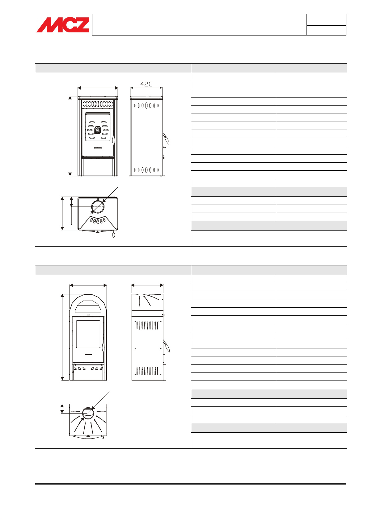
3.2. DESIGN LINE
VENUS Technical specifications
Fuel type Wood - Chips
Hourly consumption 2.0 kg/h – 1.4 kg/h
Maximum thermal power kW 7.4 Kcal 6364
Minimum thermal power kW 3.9 Kcal 3354
Efficiency 84,6 %
Heatable volume * 159/40 - 182/35 - 212/30
Minimum draught 12 Pa / 0.12 mbar
Smoke temperature 250 °C
Smoke outlet Ø 15 cm
Furnace dimensions 32.5 x 32 - h 40
Net weight Kg 170
External combustion air outlet cm² 150
CO2 emission in smoke (13 %O2) 0,10 %
0
270
5
2
1
5
1
Ø
Massive smoke capacity 8.5 g/s
Flue pipe
Up to 5 mt 20x30 cm Ø22
Between 5 and 7 mt. 20x20 cm Ø20
Over 7 mt 18x18 cm Ø18
Note
A stove is an intermittent combustion device
* Data may vary according to the fuel used
Technical features and technical specifications
Technical service - MCZ S.p.A. all rights reserved - Reproduction prohibited
Page 16
520
4
2
0
Ø
1
5
0
1
1
5
1
1
5
5
500
423
INSTALLATION AND USE MANUAL
ORION Technical specifications
Fuel type Wood - Chips
Hourly consumption 2.0 kg/h – 1.4 kg/h
Maximum thermal power kW 7.4 Kcal 6364
Minimum thermal power kW 3.9 Kcal 3354
Efficiency 84,6 %
Heatable volume * 159/40 - 182/35 - 212/30
6
2
0
1
8
2
1
Minimum draught 12 Pa / 0.12 mbar
Smoke temperature 250 °C
Smoke outlet Ø 15 cm
Furnace dimensions 32.5 x 32 - h 40
Net weight Kg 170
External combustion air outlet cm² 150
CO2 emission in smoke (13 %O2) 0,10 %
Massive smoke capacity 8.5 g/s
Flue pipe
Up to 5 mt 20x30 cm Ø22
Between 5 and 7 mt. 20x20 cm Ø20
Over 7 mt 18x18 cm Ø18
Note
A stove is an intermittent combustion device
* Data may vary according to the fuel used
ALPHA Technical specifications
Fuel type Wood - Chips
Hourly consumption 2.0 kg/h – 1.4 kg/h
Maximum thermal power kW 7.4 Kcal 6364
Minimum thermal power kW 3.9 Kcal 3354
Efficiency 84,6 %
Heatable volume * 159/40 - 182/35 - 212/30
Minimum draught 12 Pa / 0.12 mbar
Smoke temperature 250 °C
Smoke outlet Ø 15 cm
Furnace dimensions 32.5 x 32 - h 40
Net weight Kg 170
External combustion air outlet cm² 150
CO2 emission in smoke (13 %O2) 0,10 %
Massive smoke capacity 8.5 g/s
0
5
1
Ø
Flue pipe
Up to 5 mt 20x30 cm Ø22
Between 5 and 7 mt. 20x20 cm Ø20
Over 7 mt 18x18 cm Ø18
Note
A stove is an intermittent combustion device
* Data may vary according to the fuel used
Chapter 3
page
16
Technical features and technical specifications
Technical service - MCZ S.p.A. all rights reserved - Reproduction prohibited
Page 17
1
2
4
2
520
447
1
1
0
1
3
1
3
520
420
INSTALLATION AND USE MANUAL
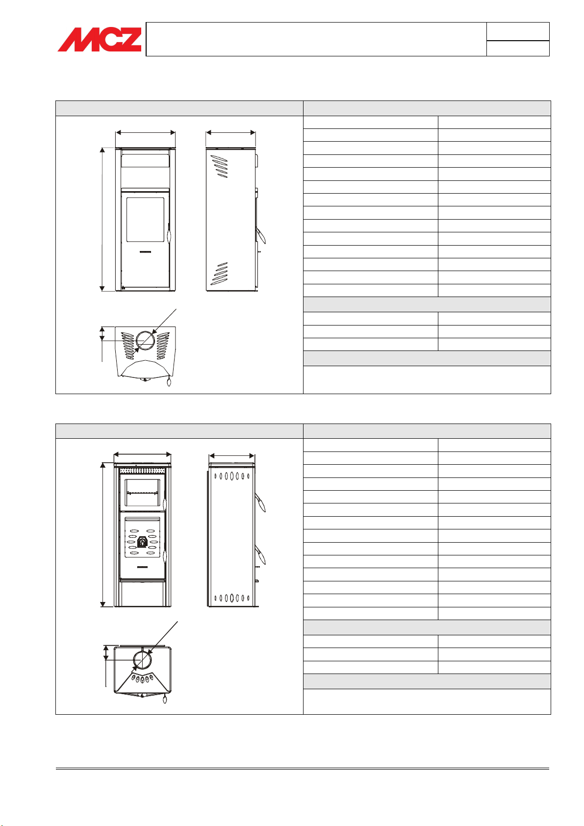
ZENIT Technical specifications
Fuel type Wood - Chips
Hourly consumption 2.0 kg/h – 1.4 kg/h
Maximum thermal power kW 7.4 Kcal 6364
Minimum thermal power kW 3.9 Kcal 3354
Efficiency 84,6 %
Heatable volume * 159/40 - 182/35 - 212/30
Minimum draught 12 Pa / 0.12 mbar
Smoke temperature 250 °C
Smoke outlet Ø 15 cm
Furnace dimensions 32.5 x 32 - h 40
Net weight Kg 170
External combustion air outlet cm² 150
CO2 emission in smoke (13 %O2) 0,10 %
Massive smoke capacity 8.5 g/s
0
5
1
Ø
Flue pipe
Up to 5 mt 20x30 cm Ø22
Between 5 and 7 mt. 20x20 cm Ø20
Over 7 mt 18x18 cm Ø18
Note
A stove is an intermittent combustion device
* Data may vary according to the fuel used
Chapter 3
page
17
SIRIO Technical specifications
Fuel type Wood - Chips
Hourly consumption 2.0 kg/h – 1.4 kg/h
Maximum thermal power kW 7.4 Kcal 6364
Minimum thermal power kW 3.9 Kcal 3354
Efficiency 84,6 %
Heatable volume * 159/40 - 182/35 - 212/30
Minimum draught 12 Pa / 0.12 mbar
Smoke temperature 250 °C
Smoke outlet Ø 15 cm
Furnace dimensions 32.5 x 32 - h 40
Net weight Kg 170
External combustion air outlet cm² 150
CO2 emission in smoke (13 %O2) 0,10 %
0
5
1
Ø
0
2
1
Massive smoke capacity 8.5 g/s
Flue pipe
Up to 5 mt 20x30 cm Ø22
Between 5 and 7 mt. 20x20 cm Ø20
Over 7 mt 18x18 cm Ø18
Note
A stove is an intermittent combustion device
* Data may vary according to the fuel used
Technical features and technical specifications
Technical service - MCZ S.p.A. all rights reserved - Reproduction prohibited
Page 18
540
462
270
1
3
1
2
INSTALLATION AND USE MANUAL
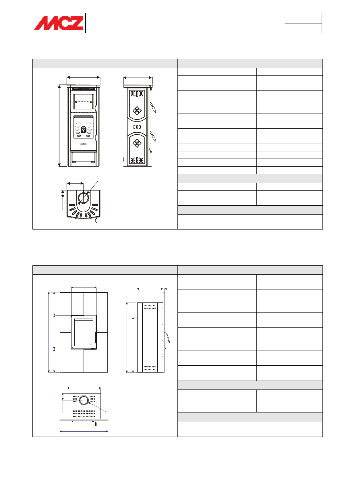
COMETA Technical specifications
Fuel type Wood - Chips
Hourly consumption 2.0 kg/h – 1.4 kg/h
Maximum thermal power kW 7.4 Kcal 6364
Minimum thermal power kW 3.9 Kcal 3354
Efficiency 84,6 %
Heatable volume * 159/40 - 182/35 - 212/30
Minimum draught 12 Pa / 0.12 mbar
Smoke temperature 250 °C
Smoke outlet Ø 15 cm
Furnace dimensions 32.5 x 32 - h 40
Net weight Kg 170
External combustion air outlet cm² 150
CO2 emission in smoke (13 %O2) 0,10 %
Massive smoke capacity 8.5 g/s
0
5
1
Ø
5
2
1
Flue pipe
Up to 5 mt 20x30 cm Ø22
Between 5 and 7 mt. 20x20 cm Ø20
Over 7 mt 18x18 cm Ø18
Note
A stove is an intermittent combustion device
* Data may vary according to the fuel used
Chapter 3
page
18
3.3. MODULO LINE
MODULO Technical specifications
Fuel type Wood - Chips
470
5
3
4
0
0
0
5
3
1
6
5
3
4
625
5
,
1
3
1
900
Ø
1
5
0
0
1
3
1
485,5
2
3
0
1
32
Hourly consumption 3.1 kg/h – 2.2 kg/h
Maximum thermal power kW 12 Kcal 10320
Minimum thermal power kW 4.5 Kcal 3870
Efficiency 87,6%
Heatable volume * 258/40 - 295/35 - 344/30
Minimum draught 12 Pa / 0.12 mbar
Smoke temperature 300 °C
Smoke outlet Ø 15 cm
Furnace dimensions 42.5 x 40 - h 43.5
Net weight Kg 215
External combustion air outlet cm² 150
CO2 emission in smoke (13 %O2) 0,11%
Massive smoke capacity 11.2 g/s
Flue pipe
Up to 5 mt 20x30 cm Ø22
Between 5 and 7 mt. 20x20 cm Ø20
Over 7 mt 18x18 cm Ø18
Note
A stove is an intermittent combustion device
* Data may vary according to the fuel used
Technical features and technical specifications
Technical service - MCZ S.p.A. all rights reserved - Reproduction prohibited
Page 19
3
0
0
M
i
n
INSTALLATION AND USE MANUAL
4. INSTALLATION AND ASSEMBLY
IMPORTANT!
The stove must be installed and connected to the
chimney flue by specialised technicians or skilled
personnel so that every local or national regulation is
met and, in any case, in accordance with regulation
UNI 10683 REV.
When the stove and frame is unpacked, make sure all parts are in
perfect working order and check for damages due to transport.
If the stove is installed in a place that is difficult to access, the weight
can be reduced by removing internal elements in the furnace. Please
remember to correctly reassemble all elements.
4.1. PREPARATION AND UNPACKING
Chapter 4
page
19
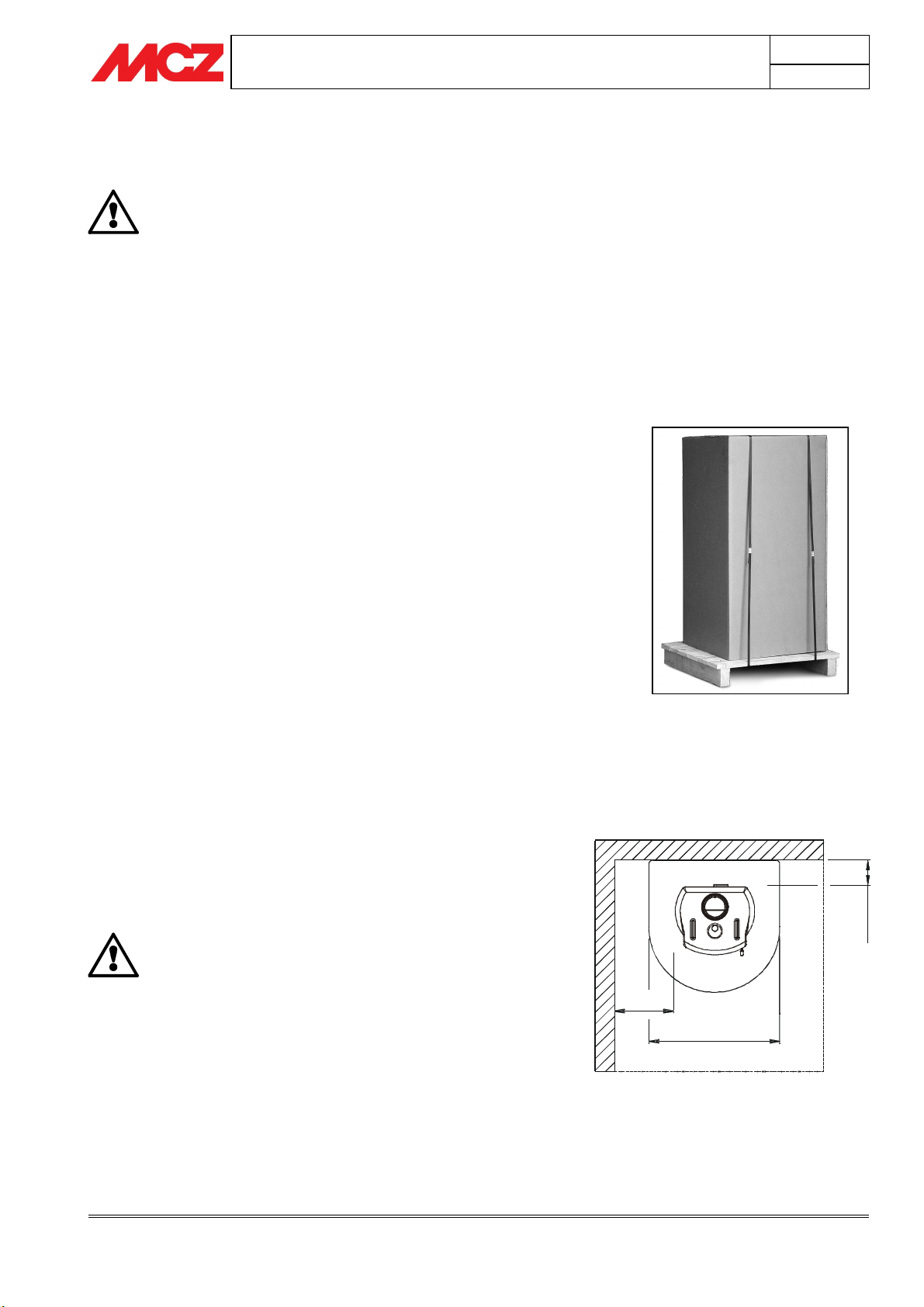
Open the packaging, remove the brackets, remove the stove from the
platform and position it in the selected area making sure it meets that
foreseen.
The stove must always be kept upright and exclusively moved with a
trolley. Pay careful attention that the door and its glass are protected
from mechanical collisions that could jeopardise their integrity.
Moving the product must always be done with care. If possible, unpack
the stove in the area where it is to be installed.
Packaging material is non-toxic, therefore it does not require special
disposal.
The end use must store, dispose or recycle packaging material in
accordance with local regulations.
4.2. POSITIONING
Always assess the static conditions of the floor that will hold the weight.
If the rear wall is made of flammable material, insulate it and
place the stove at least 30 cm from the wall. Lateral insulation
must reach at least 50 cm from the right, left and top corners.
If the stove is installed on a flammable floor,
adequate insulation is recommended.
Heat sensitive or flammable parts and objects cannot
be stored near the stove: keep these object or parts
at least 100 cm away from the most protruding stove
part.
Stove packaging example
500
1000
Installation and assembly
Technical service - MCZ S.p.A. all rights reserved - Reproduction prohibited
Page 20
INSTALLATION AND USE MANUAL
4.3. ASSEMBLY AND FEET ADJUSTMENT
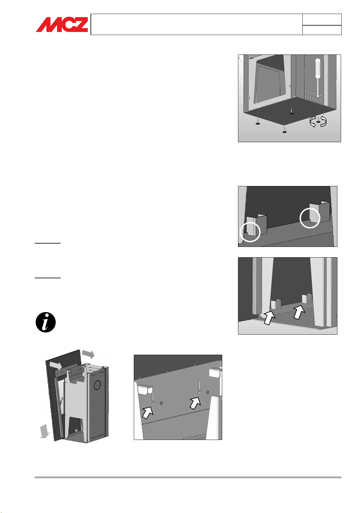
Some models require the assembly of support feet whose purpose is to
level the stove to be well-aligned and stable. For the Wood Module, the
feet also lift the structure to prevent the decorative frame from coming
into contact with the floor. Correct adjustment requires the frame to be
about 0.5 cm above the floor.
The feet are screwed into the structure base and can be installed as
illustrated and adjusted using a screwdriver.
4.4. CERAMICS ASSEMBLY
For the assembly of ceramics for each specific wood stove model,
please see the ceramics installation manual in the latter's packaging.
Assembly instructions for the Modulo product decorative frame are
included below.
4.5. FRAME ASSEMBLY (WOOD MODULE)
Chapter 4
page
20
For stove frame assembly, after unpacking, remove the top of the
stove, unscrewing the four screws on the top, place the frame on the
structure and continue as indicated below
PHASE 1
Near and fit the lower frame supports in the slots on the lower part of
the stove structure.
PHASE 2
Near the frame and fit the top edge of the structure so the screws
match the holes on the structure. Secure the frame with the fastening
screws as illustrated.
After levelling the last tile, make sure the cornice is fastened
correctly to the structure of the heater, checking that the
latter is firmly anchored.
Phase 1 Fit the lower frame supports on
the lower part of the structure
Phase 2 Match the frame to the structure as illustrated and secure using the
fastening screws and bolts
Installation and assembly
Technical service - MCZ S.p.A. all rights reserved - Reproduction prohibited
Page 21
INSTALLATION AND USE MANUAL
5. OPERATION
5.1. PRE-LIGHTING WARNINGS
Make sure you have read and completely understood the contents of
this instruction booklet.
Remove any components which might burn from the stove and door
(various instructions and adhesive labels).
Remove the stickers from the ceramic glass or the high temperature
could melt them and irreparably damage the glass. In this case, the
MCZ warranty does not cover the glass.
The stove can be installed in a corner or against a wall.
Avoid touching the stove the first time it is used since its
paint completes drying and hardens in this phase.
It is good practice to provide plenty of ventilation in the room
during the initial lighting, as the stove will give off a small
amount of smoke and smell of paint.
If necessary, touch up the paint with the aerosol spray in the
original colour (see "stove accessories”)
Chapter 5
page
21
Do not stay near the stove, and as previously mentioned, ventilate the
room. The smoke and the smell of paint will vanish after about one
hour of operation. There are no health risks involved.
The stove will be subject to expansion and contraction
during the stages of lighting and cooling down, and
may therefore make slight creaking noises.
This phenomenon is absolutely normal, the structure
being made of sheet steel, and must not be considered
a fault.
It is extremely important to be sure not to take the
stove to full heat straight away, but to bring it
gradually up to temperature.
This avoids damages to seals and the steel structure.
Do not demand full heating
performance straight away!
5.2. FUEL
FUEL: Wood
To get the best performance from your stove, it is of prime importance
to use firewood with suitable characteristics.
It is possible to use firewood such as oak, beech, ash, robinia or
ilex, or manmade logs from compressed wood without added resins.
These have a high calorific power and must be used with
caution to avoid overheating which could damage the stove.
Operation
Technical service - MCZ S.p.A. all rights reserved - Reproduction prohibited
Page 22
INSTALLATION AND USE MANUAL
Fuels such as poplar, pine, lime and chestnut have a low calorific value,
being soft woods, soft in the sense of being pulpy, and they do not burn
long. For all listed types, the humidity contained in them is a
fundamental factor.
A high percentage of moisture produces condensation in the
smoke duct causing an alteration in the draught and
generating smoke and a significant deposit of soot in the
firebox, on the glass of the door and in the flue pipe with a
possible risk of a chimney fire later on. It also causes a
considerable overall drop in efficiency.
The use of damp or treated wood emits a higher quantity of
smoke than normal that can dirty glass faster. Also the low
performance of the chimney flue can jeopardise glass
cleanliness since smoke remains in the combustion chamber
longer than normal.
Do not use treated fuels (such as painted or varnished
wood) or unsuitable materials (such as plastics and
derivatives), which could release toxic or polluting
substances.
Do not burn rubbish.
The gases produced by combustion based on the use
of unsuitable fuels cause damage to the stove and the
chimney, they cause pollution and can significantly
compromise your health.
Chapter 5
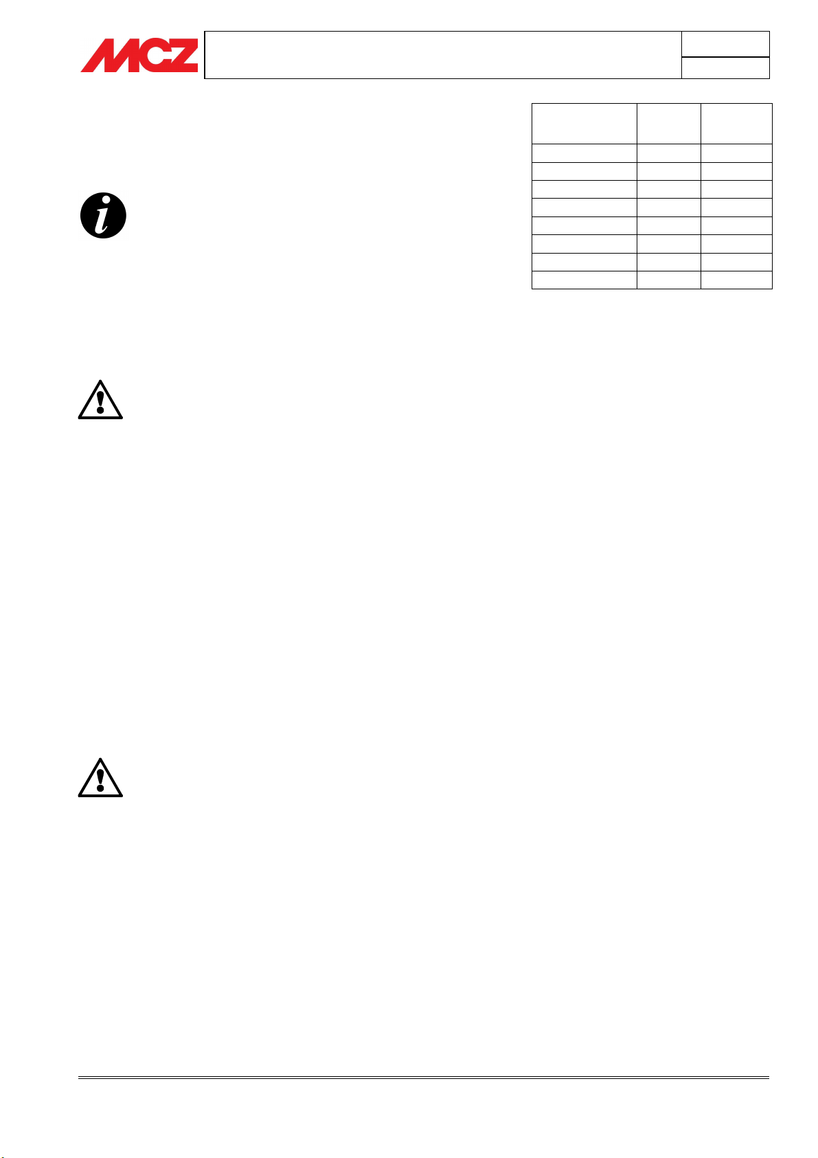
Wood drying
time (i.e. beech)
Freshly cut 50 /
3 months
6 months 35 2700
9 months 30 2900
12 months 25 3150
15 months 20 3400
18 months 15 3710
21 months 10 3980
%
humidity
40 2410
page
Kcal/h
22
Heat
power
5.3. STOVE USE
5.3.1. LOADING THE FUEL
To load fuel, simply open the door by rotating/lifting the handle and
pulling the door open.
During use, the metal parts and the glass reach high temperatures, so it
is necessary to use the special thermal glove supplied.
During combustion, the combustion chamber door must remain
closed.
Loading quantities of fuel over those indicated in the
technical sheets for each single product is prohibited.
Excessive quantities of fuel in the combustion
chamber could damage and deform the furnace and
stove structure.
MCZ is not liable for any damages caused by
overloaded fuel of the use of fuel that does not meet
specifications.
5.3.2. CONTROL OF COMBUSTION
According to the stove model, combustion regulation and therefore
combustion air intake is slightly different but always adjustable using a
simple lever or knob. Simply moving or rotating this lever increases or
decreases the quantity of air entering the combustion chamber.
Entering air is divided in:
Operation
Technical service - MCZ S.p.A. all rights reserved - Reproduction prohibited
Page 23
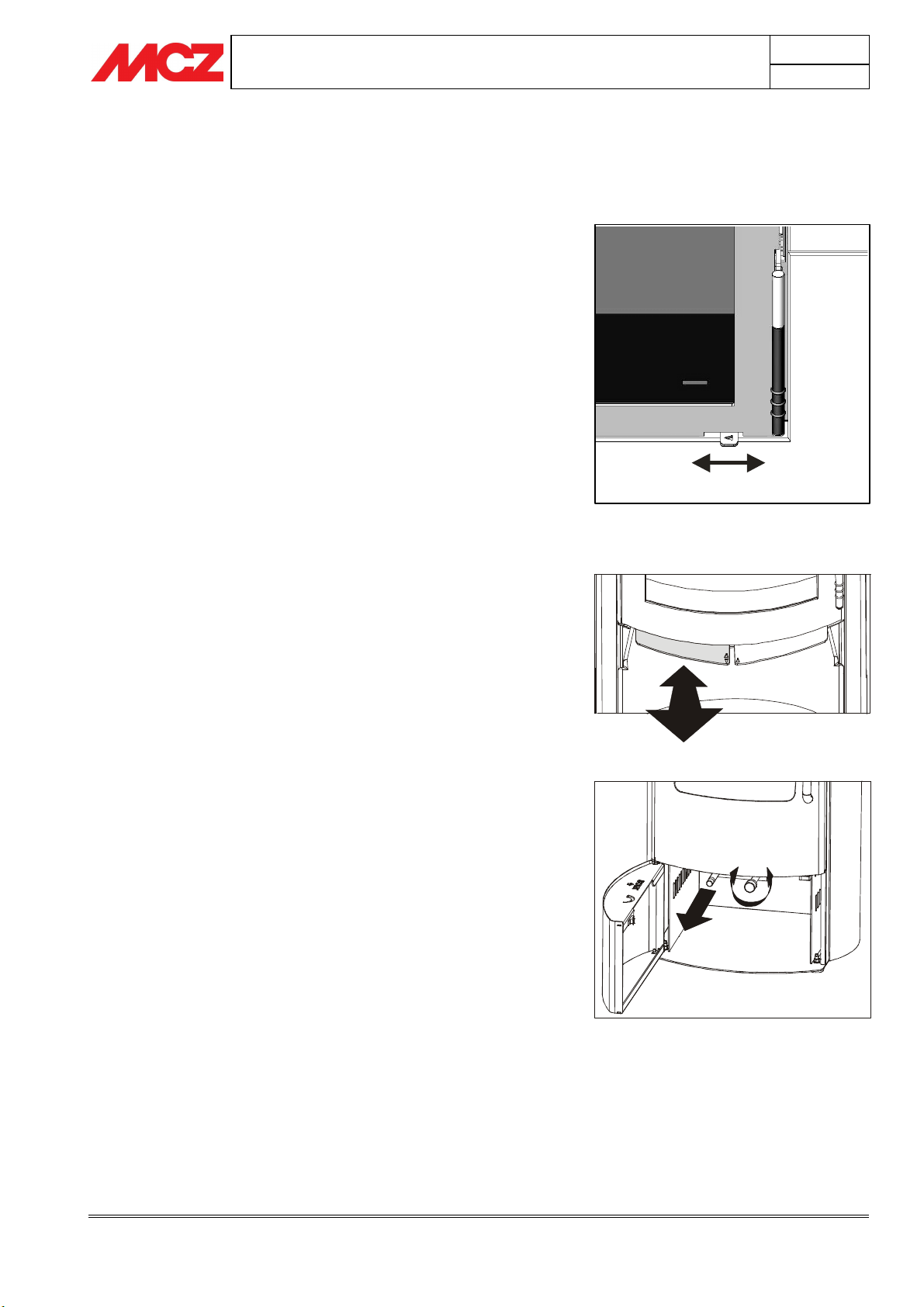
PRIMARY AIR:
Primary air is that emitted at the base of the flame to promote stove
lighting
SECONDARY AIR:
Secondary air emission is set and used to partially clean the glass
permitting the combustion process to be completed. Thanks to this, if
well calibrated, stove yield and heating performance is improved.
INSTALLATION AND USE MANUAL
5.3.2.1. Model adjustments: LUNA – MYRIA –
ANTHEA – MODULO
Move the regulation lever to the right to increase combustion air
entrance in the combustion chamber. Vice versa, move the lever to the
left to reduce entrance.
Primary and secondary air entrance is set; moving the lever
automatically sets the quantity of incoming primary and secondary air.
MIN
Chapter 5
page
23
MAX
5.3.2.2. Model adjustments: QUASAR – ORION –
SIRIO – VENUS – COMETA – ZENIT – ALPHA
Pull out the regulation lever to increase the entrance of combustion air
in the combustion chamber. Vice versa, push in the lever to decrease it.
Primary and secondary air entrance is set; moving the lever
automatically sets the quantity of incoming primary and secondary air.
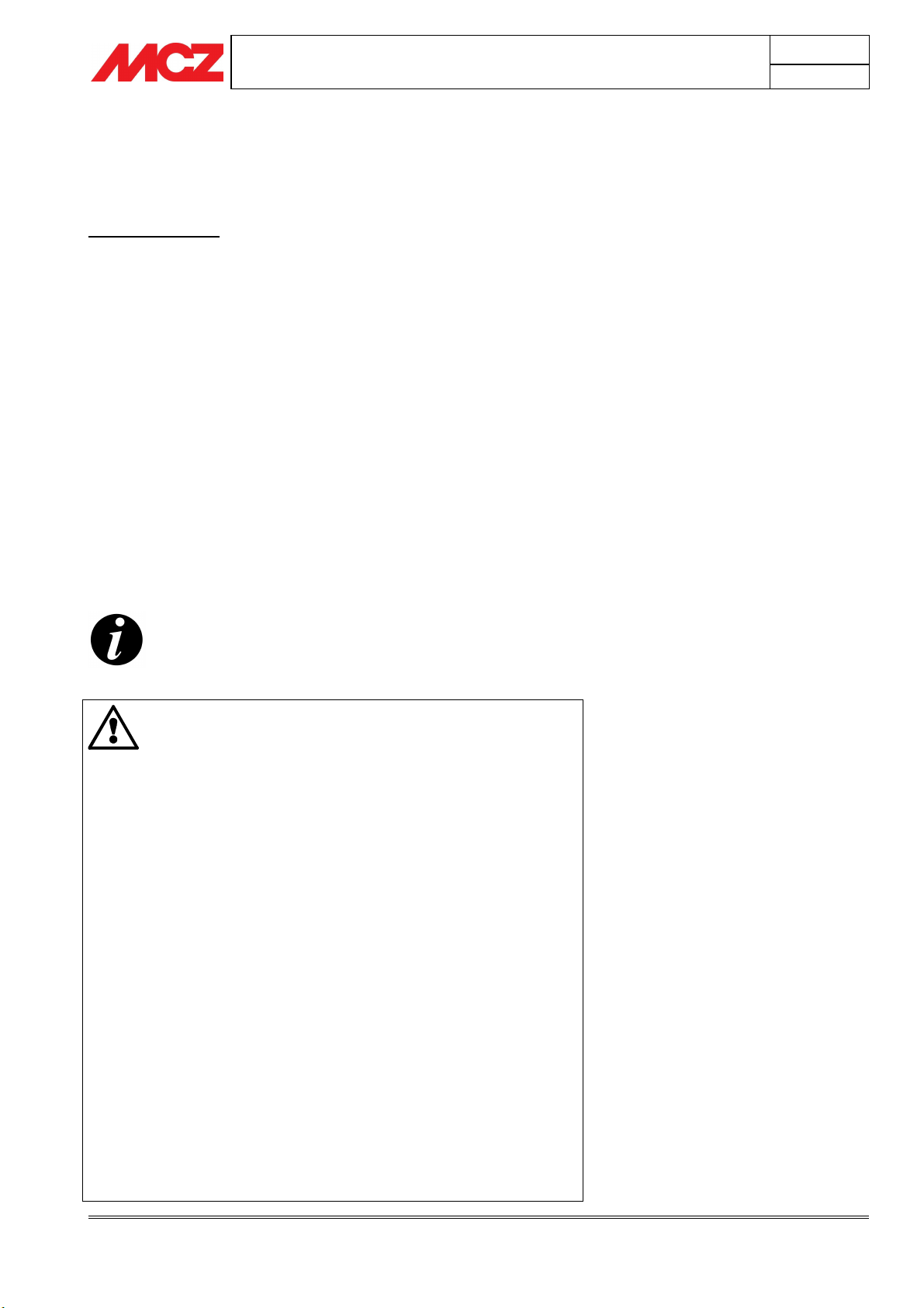
5.3.2.3. Model adjustments: PULSAR – NADIR
Combustion air regulation in these model is slightly different than the
previous in that primary and secondary air regulation are independent.
PRIMARY AIR or START LEVER
The left lever, marked “START” on the wood door, brings a large
quantity of primary air under the furnace fire surface to quickly and
efficiently light the fire. To do this, push the lever to the limit stop.
15 minutes after light the fire, this lever should be closed pulling
it out to its limit stop. From this moment, regulations are only made
with the secondary air knob.
SECONDARY AIR AND POST-COMBUSTION KNOB
Use this knob to regulate secondary air entrance to the combustion
chamber. As mentioned, secondary air is the one that permits
combustion to complete and improves yield. Rotate the knob counterclockwise to increase the quantity of incoming air; vice versa, rotate the
knob clockwise to reduce the quantity of air in the combustion chamber.
5.3.3. FIRST LIGHTING
It is advisable to approach the first lighting with caution, using
good-quality, well-seasoned wood.
Combustion air entrance must be fully open. Once combustion has
started, pieces of wood of normal size may be added.
Operation
Technical service - MCZ S.p.A. all rights reserved - Reproduction prohibited
Page 24
INSTALLATION AND USE MANUAL
The flame must have as far as possible a smooth and laminar flow.
On the various occasions when the stove needs reloading, the
door should be opened slowly, to avoid blowbacks of smoke
into the room.
Proceed as follows:
• Place a small amount of balled paper in the stove.
• Cover the paper with a small quantity of twigs and a few
pieces of wood.
• Fully open the combustion air regulator.
• Light the paper and, if necessary, keep the door open for
several minutes until the combustion chamber and chimney
flue are heated.
• When the twigs are burning, the door can be closed.
As the fire burns, add wood. Never overload the stove with wood (see
technical specifications in the table).
As soon as the flames have died down and a bed of embers has
formed, load the stove in the normal way.
Small loads of wood are preferable to large ones for
combustion.
We suggest this fuel loading method is adopted even in subsequent
product use.
To obtain nominal power, place the load of wood indicated
in the technical specifications table in the combustion
chamber (
chapter 3
). Stove autonomy is about 45 minutes.
When the fire dies down, load the stove again.
Chapter 5
page
24
Attention
• Do not use volatile, flammable substances
(petrol, alcohol etc.) for lighting the fire.
• Do not use fuels which could release toxic
substances or pollutants.
• Do not put the fire out by throwing water on it.
• Check the external and internal air intakes, and
the flue pipe, at least once a year, arranging for
them to be cleaned.
• During use, the metal parts and the glass reach
high temperatures. For all jobs of loading the
stove, adjustment or cleaning the ash drawer,
use the insulating glove provided..
• Never leave children unattended near the stove
when it is in use.
• The risk of burns from contact with hot surfaces
is very high.
• In the event of poor weather conditions for stove
use (low pressure, temperate temperatures,
wind) reversed draught may occur in the chimney
flue. If this occurs, use a small quantity of paper
to heat the chimney flue and restore normal
draught. Afterwards, proceed with normal stove
lighting.
Operation
Technical service - MCZ S.p.A. all rights reserved - Reproduction prohibited
Page 25

INSTALLATION AND USE MANUAL
5.4. EMERGENCY TREATMENT
If for any reason the stove fire needs to be suddenly and quickly put
out or a fire in the chimney flue needs to be put out, proceed as
follows:
• If time allows, remove the grate and ashes, using a metal
container.
• Put the fire out rapidly by means of a dry carbon dioxide (CO
extinguisher
2
Chapter 5
page
25
)
Operation
Technical service - MCZ S.p.A. all rights reserved - Reproduction prohibited
Page 26
INSTALLATION AND USE MANUAL
6. MAINTENANCE AND CLEANING
ATTENTION!
All cleaning operations of all parts should be
conducted with the stove cold.
6.1. CLEANING TO BE PERFORMED BY THE USER
6.1.1. Cleaning the glass
Specific products can be used to clean the glass (see our pricelist), a
cloth dampened with water and ammonia or a bit of white ash and a
newspaper. Any soot and dirt accumulations take longer to clean.
ATTENTION!
Do not spray the product on the painted parts or on
the gaskets of the door (ceramic fibre cord)
The ceramic glass installed on MCZ products are resistant to
heat up to 750°C and are tested and inspected before and
after assembly to check for cracks, bubbles and holes.
Glass, although highly resistant to temperatures, is a fragile
element and therefore the door should be handled with care
without slamming or forcing it. Glass, since it is not elastic,
can break.
This type of glass does not burst or shatter but if it should
break, due to the above, it will only crack.
Chapter 6
page
26
6.1.2. Cleaning upper calorite deflectors
They do not require particular care. With prolonged use, however, the
effective but porous material of which the deflectors inside the firebox
are made, wears out or can get damaged. Only when their thickness is
reduced by half or they break is it necessary to replace them.
6.1.3. Cleaning out the ashes
This operation should be performed with the stove off. Adequate ash
drawer cleaning is also recommended for correct combustion.
Ashes which are still hot must not be dumped outside in an
uncontrolled manner or put in the dustbin. Leave them to cool
down in the open air in a metal container.
6.1.4. Cleaning of stainless steel and satin-finish surfaces
Normally these surfaces do not need to be treated, but if they do,
avoid cleaning them with abrasive materials. For surfaces in stainless
and satin brushed steel we recommend cleaning with a paper towel or a
clean dry cloth moistened with a detergent based on non-ionic
surfactants ( < 5%). A spray glass cleaner may be used.
Maintenance and cleaning
Technical service - MCZ S.p.A. all rights reserved - Reproduction prohibited
Page 27
INSTALLATION AND USE MANUAL
6.1.5. Cleaning of painted parts
Do not clean the painted parts with wet rags when the unit is in
operation or hot to prevent thermal shock to the paint which may cause
it to detach. Do not use abrasive or aggressive products or materials.
Clean with damp cotton or paper towels.
The silicon paints used to paint MCZ products possess the
highest quality technical characteristics that make them
resistant to very high temperatures.
There is however a physical limit (380°-400°) beyond which
the paint begins to fade or (over 450°) to vitrify; it may then
flake and detach from the steel surface. If these effects are
noticed, it means temperatures have been reached that are
well above those at which the product should properly
operate. Therefore, you should use the amount of fuel
specified in the technical tables.
6.1.6. Cleaning and characteristics of marble and
steatite cladding.
Steatite and marble are natural materials taken from
blocks of stone and then worked. Therefore, veins,
colour variations or other characteristics are natural
parts of the stone and should not be considered
defects.
It is important to clean carefully and with the correct
products. Cleaning the cladding incorrectly may stain
or damage the finish of the stone or marble.
Cleaning of these materials is very important and delicate. It must be
done using materials that are specifically for stone/marble.
Carefully follow the instructions on the packages of the special products
used for cleaning. Generally, you should always use water-based
materials and a soft cotton cloth.
Chapter 6
page
27
6.1.7. Cleaning flue pipe
Mechanical cleaning of the flue pipe is recommended at least once a
year. Excessive deposits of unburnt solid material can cause problems
with the evacuation of smoke, and gives rise to a risk of chimney fires
6.2. CLEANING BY SPECIALISED PERSONNEL
WARNING:
The frequency with which the stove is cleaned should
be determined based on the type of use that is made
of the stove and the type of installation.
MCZ suggests relying on an authorized service centre
for end-of-season cleaning and maintenance, who will
carry out all of the previously mentioned work and
make a general check of the stove's components.
Maintenance and cleaning
Technical service - MCZ S.p.A. all rights reserved - Reproduction prohibited
 Loading...