

Page 1

Replacement Parts List No. 047654300
Revision W 08/12
Applied Rooftop
RPS, RCS, RFS
Sizes 018-100
Vintage B
RBS, RDS, RHS, RWS
Sizes 800-808
Vintage B
To find your Daikin McQuay Parts distributor, call 1-800-377-2787 or visit www.DaikinMcQuay.com
Page 2

Table of Contents
Parts List Revision History ........................................................................................................................ 4
Unit Model & Serial Number Nomenclature .............................................................................................5
Unit Nomenclature Complete ................................................................................................................6- 9
Model R*S Electrical Legend ............................................................................................................. 10, 11
Control Box Component Location Diagram ...........................................................................................12
Condenser Section
Condenser Control Box Diagrams .................................................................................................13, 14
Compressor Contactor Components ...................................................................................................15
Condenser Fan Motor Contactor Components .................................................................................... 16
Miscellaneous Components ........................................................................................................... 17, 18
Compressor Pressure Controls ............................................................................................................ 19
Fan Assembly ......................................................................................................................................20
Refrigerant Piping ....................................................................................................................................21
Compressor Model Information ..............................................................................................................22
Miscellaneous Compressor Components .............................................................................................. 23
Coils
Condensing Coils ................................................................................................................................. 24
Direct Expansion Evaporator Coils
Single Draw-through Evaporator Coil / Unit Sizes 018B-030B, 82.00” ............................................. 25
Single Blow-through Evaporator Coil / Unit Sizes 036B-040B / 82.00” ............................................26
Single Blow-through Evaporator Coil / Unit Sizes 041B-100B / 82.00’’ ............................................27
Dual Blow-through Evaporator Coil / Unit Sizes 081B-100B / 82.00’’ ............................................... 28
Upper Main Control Panel: Non MicroTech (Code 20= 30, 31)
Unit Controller Diagrams - All sizes .....................................................................................................29
Diagram and Components - All sizes .............................................................................................30- 32
Upper Main Control Panel: MicroTech (Code 20= 1M, 2M, 4M)
Unit Controller Diagrams - 018- 040 ....................................................................................................33
Diagram and Components - 018- 040 ............................................................................................ 34, 35
Lower Main Control Panel
Component Location Diagram - All Sizes ............................................................................................36
Components - All Sizes ..................................................................................................................37- 53
Miscellaneous Controls
Control Locations ................................................................................................................................ 54
Components ......................................................................................................................................... 55
Electric Heat Control Panel .....................................................................................................................56
Electric Heat Power Panel
Diagram & Components ....................................................................................................................... 57
Components - All Sizes ..................................................................................................................58- 61
Hi-Limit, Disc Type ...................................................................................................................................62
Gas Burner Section
Forced Draft Burner (FDB Vintage A)
Gas Burner Final Assembly ........................................................................................................63- 65
Burner Components .................................................................................................................... 66, 67
Control Box Diagrams & Components .............................................................................................. 68
Gas Control Box Diagrams & Components, FDB110A thru 200A ....................................................69
Gas Train Components ..................................................................................................................... 70
Supply Air Fan
Supply Air Drive Nomenclature ............................................................................................................ 71
Forward Curved (FC) Fan - 15” ...........................................................................................................72
Forward Curved (FC) Fan - 24” ...........................................................................................................73
Forward Curve (FC) Fans - 27” & 30” .................................................................................................. 74
Applied Rooftop; R*S Series / Vintage B Rev. W 08/12 RPL 047654300 / Page 2
Page 3

Table of Contents, Continued
Supply Air Fan, Continued
Airfoil (AF) Fans & Variable Inlet Fans - 24” ........................................................................................75
Airfoil (AF) Fans & Variable Inlet Fans - 27” & 30” ............................................................................... 76
Forward Curve (FC) Fans ..............................................................................................................77- 79
Airfoil (AF) & Variable Inlet Fans ...................................................................................................80- 82
Variable Inlet Vanes .......................................................................................................................83- 85
Return Air Fan
Return Air Drive Nomenclature ............................................................................................................ 86
Forward Curve (FC) Fan - 15” .............................................................................................................87
Forward Curve (FC) Fan - 18” .............................................................................................................88
Forward Curve (FC) Fan - 27” .............................................................................................................89
Forward Curve (FC) Fan - 33” .............................................................................................................90
Airfoil (AF) Fans - Variable Inlet Fans - 18” .........................................................................................91
Airfoil (AF) & Variable Inlet Fans - 27” .................................................................................................92
Airfoil (AF) & Variable Inlet Fans - 33” .................................................................................................93
Airfoil (AF) Fan-Horizontal Mount - 40” ................................................................................................ 94
Variable Inlet Vanes - Horizontal Mount ..............................................................................................95
Variable Inlet Vanes ....................................................................................................................... 96, 97
Typical Blower ..........................................................................................................................................98
Supply Air Blower
Spring Vibration Mounts ...............................................................................................................99- 106
Return Air Blower
Spring Vibration Mounts .............................................................................................................107- 111
Fan Blower Motors - Supply & Return Air ............................................................................................ 112
Filter Selection
Diagrams ............................................................................................................................................ 113
Charts ........................................................................................................................................114, 115
Economizer Damper
Standard Type Damper ............................................................................................................... 116,117
Low Leak Type Damper .............................................................................................................. 118,119
Bottom Discharge Air & Return Air Opening Dampers ...............................................................120,121
Miscellaneous Cabinetry
Diagrams ............................................................................................................................................ 122
Components ....................................................................................................................................... 123
Wall Mounted Controls and Accessories ...........................................................................................124
Applied Rooftop; R*S Series / Vintage B Rev. W 08/12 RPL 047654300 / Page 3
Page 4

Parts List Revision History
Revision Date Description
A 4/98 Supersedes Replacement Parts List No. 476543Y-00 dated 4/89. Includes new information.
Completely re-done to be consistent with OnLine/CD format.
B 2/99 Page 60: Corrected part number for Fan Wheel Housing, Variable Inlet Fan (Bubble #35).
C 12/99 Page 48: Corrected description for Enthalpy Control (Electromechanical) and added Enthalpy
Control (Electronic), Schematic Symbol EC1.
D 8/00 Page 16: Added motor, 1.5 hp, 3 ph, 575/6/3, p/n 046744200.
E 2/01 Page 105: Bub #11 Damper Blade part #’s changed; 37.08” was 058386821, is now 044195101;
57.08” was 058386822, is now 044195102; 81.08” was 058386823, is now 044195103.
F 7/01 Page 39-46: Added note; “DUE TO UNIT SPECIALS - Request vendor information and
contact SMG in Minneapolis”.
G 5/02 Pages 66 & 67: Bubbles 69 and 70 were switched.
H 9/03 Page 23: Model number was incorrect in table heading, 610B is now 061B.
J 10/04 Page 18: Removed Copeland compressor information.
K 9/05 Page 56: Schematic Symbol R13 pn 280036200 was changed to 028036200.
Page 28: Added footnote #1.
L 1/06 Page 18: Removed note from compressor table.
M 7/06 Page 48: Schematic symbol TC4 pn changed from 0276672500 to 027672500.
N 11/08 Pages 39-46: Note change from SMG in Minneapolis to McQuay Parts.
Pages 96, 97, 98: Added the word “Return” to heading.
Page 3: Added the word “Return” to Fan Blower Motors - Supply & Air in TOC.
O 12/09 Updated Cover and Revision page with current logo design.
Page 78: Corrected Bub 97 p/n from 0665434242 to 066543242.
P 3/10 Page 48: Changed description of “Type of Unit Control system” for DM1 & EM1 from “All Types”
to “Honeywell/Conventional”. No DM1 or EM1 available for MicroTech controls.
Q 11/10 Converted form to current software and corrected various formatting issues. Removed all
references to Figure numbers.
Page 2, 3: Updated TOC as required.
Page 5: Created new page titled: “Unit Model & Serial Number Nomenclature”.
Page 6- 8: Added Unit Model Nomenclature Complete section.
Page 9, 10: Renamed “Model R*S Legend” section “Model R*S Electrical Legend.”
Page 59- 66: Updated Gas Burner section with information from RPL 552260Y-00 and IM684-1.
Page 67: Added SAF drive nomenclature page per dwg: 299460C00 and repaginated document.
Page 82: Added RAF drive nomenclature page per dwg: 299460C00 and repaginated document.
Page 93- 107: Added footnote regarding the changes in spring colors and to contact McQuay
Parts for current configuration.
Page 108: Updated motor section by deleting obsolete ODP standard efficiency motor p/ns.
Repaginated document.
R 3/11 Various: Corrected misc. spelling and formatting issues.
Page 67: Updated fan size list to include codes A, 2, 4, 5, 6, 7, 8, 9 only.
Page 82: Corrected Fan Size Code 3 from 22” to 40” Re-wrote footnotes to clarify information.
S 7/11 Page 118: Updated and re-arranged drawings and added Bubble numbers.
Page 119: Added additional cabinet p/ns per archived information and soft bills.
T 3/12 Cover, Pg. 4: Updated to current Daikin McQuay logo format.
Page 119: Added in Bubs #80 Door Latch Angle- L.H. 029944501 & #81 Door Latch Angle- R.H.
029944502.
U 5/12 Page 21: Corrected Compressor chart changed duplicate XIII to XII.
V 7/12 Various: Changed “McQuay Parts” to “Daikin McQuay Parts”.
Page 9, 10: Added in Microtech Schematic Symbols ref IM157-8.
Page 32- 35 (New): Added pages for Microtech control diagrams and components. Repaginated
document and updated TOC.
W 8/12 Page: 6- 8: Added in RCS, RDS, RBS nomenclature.
Page: 9 (New): Added page for additional coding. Repaginated form and updated TOC.
McQuay International, 13600 Industrial Park Blvd., P.O. Box 1551, Minneapolis, MN 55440 (763) 553-5330
Applied Rooftop; R*S Series / Vintage B Rev. W 08/12 RPL 047654300 / Page 4
Page 5

Unit Model & Serial Number Nomenclature
Model Number
R P S - 030 B E
ROOFPAK
HEAT TYPE
UNIT CONFIGURATION A = Natural Gas
P = Heating, Mechanical Cooling E = Electric
F = Heating, Future Mechanical Cooling F = Fuel Oil
C = Condensing Section Only S = Steam
W = Heating, Water Cooling W = Hot Water
H = Heating Only
B = Blow-through Air Handler
D = Draw-through Air Handler
SINGLE ZONE UNIT
Y = None (Cooling Only)
DESIGN VINTAGE
NOMINAL CAPACITY (TONS) CABINET SIZE
RPS, RFS, RCS: RBS, RDS, RHS, RWS:
018, 020, 025, 030 ..................................................................................................................................................800
036, 040 ..................................................................................................................................................................802
041, 051, 060, 070 ..................................................................................................................................................804
061, 071, 080 ..........................................................................................................................................................806
081, 090, 100 ..........................................................................................................................................................808
OR
Serial Number
3 7A 12345 01
Engineering Revision
Serial Number
Factory
3= Faribault,MN
Year and Month of
Manufacture
Year Month
U= 1989 A= Jan.
V= 1990 B= Feb.
W= 1991 C= Mar.
X= 1992 D= Apr.
Y= 1993 E= May
Z= 1994 F= Jun
5= 1995 G= Jul
6= 1996 H= Aug
7= 1997 J= Sep.
8= 1998 K= Oct.
9= 1999 L= Nov.
M= Dec.
Applied Rooftop; R*S Series / Vintage B Rev. W 08/12 RPL 047654300 / Page 5
Page 6

Unit Nomenclature Complete
R*S***B A 27 AL D Y YA Y 1 E104 Y J21F1 1 B S11YY A Y YYYYY 1M YYYY YYYY
Code 03 04 05 06 07 08 09 10 11 12 13 14 15 16 17 18 19 20 21 22
A YYYYYY UUYY A 1 YYYY A A 00
23 24 25 26 27 28 29 30 31
Code 03= Type of Heat
Y= No Heat
A= Natural Gas
B= Propane (RPS)
B= Blank Section (RDS, RBS)
E= Electric
F= Fuel Oil
S= Steam
W= Hot Water
X=Special
Code 04= Electric Power Supply
12= 208/60/3 29= 230/60/3
28= 380/50/3 27= 460/60/3
37= 575/60/3 44= 415/50/3
Code 05= Starting Option
AL= Across the Line
PW= Part Winding Start (Compressors only)
PP= Part Winding Start (Compressors & Fan Motors)
Code 06= Compressor Type (RPS, RCS)
D= Discus Y= Reed
Code 06= Electrical Power Supply (RDS, RBS)
Y= None
A= SAF 1HP- 20HP
B= SAF 25HP- 40HP
C= SAF 50HP- 60HP
E= SAF & RAF 1HP- 40HP total
F= SAF & RAF 45HP- 80HP total
G= SAF & RAF 85HP- 125HP total
X=Special
Code 07= SA/RA Fan Motor Type
Y= Standard Efficiency H= High Efficiency
Code 08= Capacity Control
Digit 1 (Number of Unloaders Furnished)
Y= 1 (018-036) & 0 (040-100)
1= 2 (025-071) & 3 (080-100)
2= 3 (051), 4 (060-071), 5 (080-081), & 6 (090-100)
X= Special
Digit 2 (Method of Control)
A= Compressor from Remote, Unloaders from Pressure
Control
C= Compressors and Unloaders from Remote, No
Pressure Control
X= Special
Code 09= Hot Gas Bypass
Y= None
1= Capacity Control Circuit #1
2= Capacity Control Circuits #1 & 2
3= Capacity Control Circuits #1, 2, 3
X= Special
Code 10= Compressor Isolation
Y= None
1= Resilient
2= Spring with Vibration Eliminators on Piping
Code 11= Cooling Specification
YYYY= None
AAAA= Section Less Coils
E001= Std. Evap Coil (2 Row 018-030, 800)
(3 Row 036-100, 802- 806)
E003= 3 Row Evap Coil (018-030 Only)
E103= 3 Row Evap Coil (10 FPI)
E123= 3 Row Evap Coil (12 FPI)
E004= 4 Row Evap Coil
E083= 3 Row Evap Coil
E084= 4 Row Evap Coil (8 FPI)
E104= 4 Row Evap Coil (10 FPI)
E124= 4 Row Evap Coil (12 FPI)
E005= 5 Row Evap Coil (8 FPI)
E085= 5 Row Evap Coil (8 FPI, 018-040 Only)
E105= 5 Row Evap Coil (10 FPI)
E125= 5 Row Evap Coil (12 FPI)
D003= 3 Row Dual Staggered Evap Coil (808)
D004= 4 Row Dual Staggered Evap Coil (808)
D005= 5 Row Dual Staggered Evap Coil (808)
D006= 6 Row Dual Staggered Evap Coil (808)
Digit 1 (Chilled Water Coil Type)
H= 5WH
L= 5WL
S= 5WS
Digit 2 (Fin Series)
A= 6 FPI
B= 8 FPI
C= 10 FPI
D= 12 FPI
Digit 3 (Rows)
3= 3 Rows
4= 4 Rows
5= 5 Rows
6= 6 Rows
Digit 4 (Coil Size)
S= Single Coil
D= 2 Staggered Coils
Digit 1 (Contractor Coil Codes)
C= Contractor Coil
F= Contractor Coil w/ F & B
Digit 2 (Fin Length)
S= 73”
L= 79”
Digit 3 (Filler Piece/Fin Height)
Y= None
1= 3” 2= 6” 3= 9” 4= 12” 5= 15’
6= 18” 7= 21” 8= 24” 9= 27- 51”
Code 12= Optional MicroTech Hardware
Y= None
M= Phone Modem
Code 13= Supply (SAF) Fan Drive
*****= 5 Digit Drive Code
(See Supply Air Drive Code Nomenclature Section.)
Applied Rooftop; R*S Series / Vintage B Rev. W 08/12 RPL 047654300 / Page 6
Page 7

Unit Nomenclature Complete, Continued
Code 14= Air Discharge
Y= None/Full Front
B= Bottom
G= Bottom w/ Plenum
H= Front w/ Plenum
1= Bottom
X= Special
Code 15= Air Return
Y= None/Full Back
G= Bottom w/ Plenum and/or Economizer
H= Back w/ Plenum and/or Economizer
J= Outside air Hood
K= Outside air Hood
B= Bottom
F= Back
X= Special
Code 16= Heating Specifications
YYYYY= None
XXXXX= Special
Electric Heat (Multi-Stage)
E02Y3= 20KW E21Y3= 210KW
E03Y3= 30KW E22Y3= 220KW
E04Y3= 40KW E24Y3= 240KW
E06Y3= 60KW E27Y3= 270KW
E08Y3= 80KW E28Y3= 280KW
E09Y3= 90KW E30Y3= 300KW
E10Y3= 100KW E32Y3= 320KW
E12Y3= 120KW E33Y3= 330KW
E14Y3= 140KW E36Y3= 360KW
E15Y3= 150KW E40Y3= 400KW
E16Y3= 160KW E44Y3= 440KW
E18Y3= 180KW E48Y3= 480KW
E20Y3= 200KW
Gas Furnace
Digit 1-3 (BTU Output)
020= 200MBH 079= 800MBH
025= 250MBH 080= 800MBH
032= 320MBH 100= 1000MBH
040= 400MBH 110= 1100MBH
050= 500MBH 140= 1400MBH
064= 640MBH 150= 1500MBH
065= 650MBH 200= 2000MBH
Digit 4 (Heat Exchanger Material)
A, B, C, D= Stainless Steel Primary, Aluminum
Secondary
S, T, U, V= Stainless Steel Primary, Stainless Steel
Secondary
Digit 5 (Burner Type)
A= One Stage Gas- Electronic
C= Two Stage Gas- Electronic
E= Modulating Gas- Electronic
G= One Stage Fuel Oil- Cad Cell
H= One Stage Fuel Oil- Electronic
J= Two Stage Fuel Oil- Cad Cell
K= Two Stage Fuel Oil- Electronic
Steam
Digit 1-3 (Coil)
S11= 5JA0601H, OR 8JA0601B
S12= 5JA1201H, OR 8JA1201B
Digit 4 (2-Way Valve Size)
D= 1” H= 2 ½”
E=1 ¼” J= 3”
F= 1 ½” Y= None
G= 2”
Digit 5 (Valve Control)
Y= None
M= Modulating w/ Spring Open
Code 16= Heating Specifications, Continued
Hot Water
Digit 1-3 (Coil)
W11= 4WH1201H, OR 5WH0901H
W22= 4WS1202H, OR 5WS0902C
Digit 4 (2-Way Valve Size)
D= 1” H= 2 ½”
E=1 ¼” J= 3”
F= 1 ½” Y= None
G= 2”
Digit 5 (Valve Control)
Y= None
M= Modulating w/ Spring Open
Code 17= Filters
Y= None
A= 2” Throwaway (Angular Rack)
B= 2” Cleanable (Angular Rack)
C= D AND/OR E Less Filters (Rack Only)
D= 45% OR 65% Eff. Cartridge/Bag Type w/ Prefilters (Flat
Rack)
E= 95% Eff. Cartridge/Bag Type w/ Prefilters (Flat Rack)
F= A AND/OR B Less Filters (Angular Rack)
G= 2” 35% Eff. Pleated Throwaway (Angular Rack)
X= Special
Code 18= Damper Control
Y= None
A= 0-30% OA, Manual Operation
B= 0-100% OA, Manual Operation
C= 0-100% OA, Remote Rheostat
D= 0-100% Economizer Package
G= 0-100% Economizer Package w/ RA Smoke Control
H= 0-100% Economizer Package w/ RA & SA Smoke Control
X= Special
Code 19= Return (RA) Fan Drive
YYYYY= None
*****= 5 Digit Drive Code
(See Return Air Drive Code Nomenclature section.)
Code 20= Temperature Control Packages
YY= None
20= Honeywell W973
21, 22= Contact Daikin McQuay Parts.
30= Field Supplied Discharge Air Control
31, 36= Honeywell W7100
35= Discharge air w/ NO Controls
1M, 2M, 3M, 4M= MicroTech Control
Code 21= Remote Control Panel (RPS, RWS, RHS)
Digit 1 (System Signal)
Y= None
1= Heat Fail
2= Cool Fail
3= 1 AND 2
X= Special
Digit 2 (Fan Signal)
Y= None
1= Fan On
X= Special
Digit 3 (Valve Control)
Y= None
1= With Filter Switch
X= Special
Digit 4 (Remote Potentiometer)
Y= None
1= With Remote Potentiometer
X= Special
Applied Rooftop; R*S Series / Vintage B Rev. W 08/12 RPL 047654300 / Page 7
Page 8

Unit Nomenclature Complete, Continued
Code 21= Heating Specification (RDS)
YYYY= None
XXXX= Special
S11Y= 5JA0601H
S12Y= 5JA1201H
W11Y= 5WH0901H
W22= 5WS0902C
Code 22= Auxiliary Control Packages (RPS, RWS, RHS)
Digit 1 (Smoke Control)
Y= None
1= Shut down Fan(s) AND Close Dampers
2 = Shut down SA Fan, Close Return Dampers, AND Run RA Fan
X= Special
Digit 2 (Morning Warmup)
Y= None
1= Energize one Stage Full Heat, Close OA Dampers, AND
Lock Out Cooling
X= Special
Digit 3 (Freezestat)
Y= None
1= Shut Down Fan(s), Close OA Dampers AND Open
Valve Full Thru Coil
X= Special
Digit 4 (Reset)
Y= None
1= Reset From Outside air Signal
2= Reset From Space/Return Air Signal (Field Installed)
X= Special
Code 22= Heating Specification (RDS)
E001= Std. Evap Coil (2 Row 800)
(3 Row 802- 806)
E003= 3 Row Evap Coil
E004= 4 Row Evap Coil
E005= 5 Row Evap Coil
D003= 3 Row Dual Staggered Evap Coil (808)
D004= 4 Row Dual Staggered Evap Coil (808)
D005= 5 Row Dual Staggered Evap Coil (808)
D006= 6 Row Dual Staggered Evap Coil (808)
Digit 1 (Chilled Water Unit Coil Type)
H= 5WH
L= 5WL
S= 5WS
Digit 2 (Fin Series)
A= 6 FPI
B= 8 FPI
C= 10 FPI
D= 12 FPI
Digit 3 (Rows)
3= 3 Rows
4= 4 Rows
5= 5 Rows
6= 6 Rows
Digit 4 (Coil Size)
S= Single Coil
D= 2 Staggered Coils
Digit 1 (Contractor Coil Codes)
C= Contractor Coil
F= Contractor Coil w/ F & B
Digit 2 (Fin Length)
S= 73”
L= 79”
Code 22= Heating Specification (RDS), Continued
Digit 3 (Coil Position)
A=5
B= 5 & 6
C= 5 & 7
D= 5- 8
Digit 4 (Filler Piece/Fin Height)
1= 3” 2= 6” 3= 9” 4= 12” 5= 15’
6= 18” 7= 21” 8= 24” 9= 27- 51”
Code 23= Disconnect Switch
Y= None
A= Integral Disconnect Switch (Non-Auto)
E= SAF and/or RAF 1HP- 40HP total
F= SAF and/or RAF 45HP- 80HP total
G= SAF and/or RAF 85HP- 120HP total
X= Special
Code 24= Air Flow Control Packages (RPS, RWS, RHS)
Non-MicroTech Control: Code 20= 30, 31
Digit 1 (Type of System)
Y= None
D= Discharge Damper
V= Inlet Vane
X= Special
Digit 2 (Type of Control)
Y= None
E= Electronic
F= Floating
X= Special
Digit 3 (Number of Sensors)
Y= None
1- 6= Number of included Sensors
X= Special
Digit 4 (Remote Potentiometer)
Y= None
M= Unit Mounted
X= Special
Digit 5 Remote Return)
Y= None
1= With Remote Return
X= Special
Digit 6 (Remote Metering)
Y= None
1= With Remote Metering
X= Special
MicroTech Control: Code 20= 1M, 2M, 3M, 4M
Digit 1 (Type of System)
Y= None
D= Discharge Damper
V= Inlet Vane
X= Special
Digit 2 (Type of Control)
Y= None
M= MicroTech
X= Special
Digit 3 (Number of Sensors)
Y= None
1= 1 Duct
2= 2 Duct
3= 1 Duct AND 1 Space
4= 1 Space
X= Special
Digit 4 (Remote Potentiometer)
Y= None
X= Special
Applied Rooftop; R*S Series / Vintage B Rev. W 08/12 RPL 047654300 / Page 8
Page 9

Unit Nomenclature Complete, Continued
Code 24= Air Flow Control Packages (RPS, RWS, RHS), Cont.
Digit 5 (No Requirement)
Y= None
X= Special
Digit 6 (No Requirement)
Y= None
X= Special
Code 24= Discharge Dampers (RDS, RBS)
YYYYYY= None
D11111= Supply Air Dampers
B11111= Supply & Return Air Dampers
XXXXXX= Special
Code 25= Approval Listing
Digit 1 (Unit Approval)
Y= None
C= ETL/Canada OR CSA/MEA
E= ETL/MEA
L= LA Code
U= UL
Digit 2 (Burner Approval)
Y= None
C= ETL-C (0-2000 Feet Altitude) OR CSA
D= ETL-C (2000-4500 Feet Altitude) OR CSA
U= UL
Digit 3 (Burner Approval)
Y= None
A= FIA
F= FM
Digit 4 (No Requirement)
Y= None
Code 26= Parts Warranty
A= Standard One Year Parts
C= Extended One Year Parts/Two Year Total
Z=Special
Code 30= Heat Exchanger Warranty
Y= None
A= Standard One Year Heat Exchanger
R= Extended Nine Year Heat Exchanger/Ten Year Total
Z=Special
Code 31= Latest Code Sheet Revision
**= Two Digit Code
Code 27= Packaging
1= Steel Skid
D= Open Crate
F= Sheathed Crate
S= Split Unit
Z= Same as 1 except Consolidated Shipment
X=Special
Code 28=Miscellaneous
YYYY= None
1111= Oil Circulating Tank: Code 03= F
2005= High Pressure Regulator 0.5 Min. Inlet Pressure
2010= High Pressure Regulator 1.0 Min. Inlet Pressure
2020= High Pressure Regulator 2.0 Min. Inlet Pressure
2030= High Pressure Regulator 3.0 Min. Inlet Pressure
2050= High Pressure Regulator 5.0 Min. Inlet Pressure
2075= High Pressure Regulator 7.5 Min. Inlet Pressure
2100= High Pressure Regulator 10.0 Min. Inlet Pressure
XXXX= Special
Code 29= Compressor Warranty
A= Standard One Year Compressor
Q= Extended Four Year Compressor/Five Year Total
Z=Special
Applied Rooftop; R*S Series / Vintage B Rev. W 08/12 RPL 047654300 / Page 9
Page 10

Model R*S Electrical Legend
Designation Description Standard Location
ACT1 ACTUATOR MOTOR SUPPLY FAN (VANE OR DAMPER) ..................... SUPPLY AIR SECTION
ACT2 ACTUATOR MOTOR RETURN FAN (VANE OR DAMPER) .................... RETURN AIR SECTION
ADI ANALOG TO DIGITAL INTERFACE (MICROTECH) ................................ MAIN CONTROL BOX
AS BLOWER AIR SWITCH ............................................................................. FURNACE SECTION
AUX AUXILIARY ALARM CKTS. FSG............................................................... FURNACE SECTION
BM BURNER BLOWER MOTOR..................................................................... FURNACE SECTION
CS1, 2, 3 SWITCHES, REFRIGERANT CKTS. ........................................................ CONDENSER CONTROL BOX
CP1 CENTRAL PROCESSOR .......................................................................... MAIN CONTROL BOX
DAC1 DISCHARGE AIR CONTROLLER ............................................................. MAIN CONTROL BOX
DAS1 DISCHARGE AIR SATELLITE .................................................................. MAIN CONTROL BOX
DB1 DAUGHTER BOARD (EARLY MICROTECH) ........................................... MAIN CONTROL BOX
DHL DUCT HIGH LIMIT..................................................................................... EVAPORATOR SECTION
DM1 DAMPER MOTOR OUTSIDE AIR ............................................................. DAMPER SECTION
DS1 DISCONNECT SWITCH, MAIN (W/ ELECTRIC HEAT) ............................ ELECTRIC HEAT SECTION
DS1 DISCONNECT SWITCH, MAIN (W/O ELECTRIC HEAT) ......................... MAIN CONTROL BOX
DT1 DISCHARGE AIR TEMPERATURE SENSOR .......................................... DISCHARGE AIR SECTION
EC1 ENTHALPY CONTROL ............................................................................. ECONOMIZER SECTION
EM1 ECONOMIZER MOTOR ............................................................................ ECONOMIZER SECTION
EMS ENERGY MANAGEMENT SYSTEM ......................................................... MAIN CONTROL BOX
EPC ELECTRONIC PRESSURE CONTROL .................................................... MAIN CONTROL BOX
ES1 ELECTRONIC SEQUENCER .................................................................... ELECTRIC HEAT SECTION
FB1,2,3 FUSE BLOCK, COMPRESSOR MOTORS ............................................... CONDENSER CONTROL BOX
FB4,5,6,7,8 FUSE BLOCK, CONDENSER FAN MOTORS .......................................... CONDENSER CONTROL BOX
FB 9,10 FUSE BLOCK, SUPPLY AIR FAN MOTOR .............................................. MAIN CONTROL BOX
FB11,12 FUSE BLOCK, RETURN AIR FAN MOTOR ............................................. MAIN CONTROL BOX
FB13 FUSE BLOCK, CONTROL POWER .......................................................... MAIN CONTROL BOX
FB24,25,26,27 FUSE BLOCK, ELECTRIC HEAT............................................................. ELECTRIC HEAT CONTROL BOX
FD FLAME DETECTOR .................................................................................. FURNACE SECTION
FLC FAN LIMIT CONTROL ............................................................................... FURNACE SECTION
FPS FLOATING PRESSURE SWITCH ............................................................. SUPPLY AIR OUTLET
FSG FLAME SAFEGUARD ............................................................................... FURNACE SECTION
FS1 FREEZESTAT CONTROL ......................................................................... EVAPORATOR SECTION
F1 FUSE, CONTROL CIRCUIT ...................................................................... MAIN CONTROL BOX
F2 FUSE, BURNER MOTOR.......................................................................... MAIN CONTROL BOX
GF1 GROUND FAULT INTERRUPTER ............................................................ MAIN CONTROL BOX
GRD GROUND ................................................................................................... MAIN CONTROL BOX
GV1 PILOT GAS VALVE .................................................................................. FURNACE SECTION`
GV2 MAIN GAS VALVE.................................................................................... FURNACE SECTION
HL1,2,3,4,5,6,7,8,9,10,11,12 ELECTRIC HEATER LIMITS ..................................................................... ELECTRIC HEAT CONTROL BOX
HL13,14,15,16 LINEAR LIMIT, ELECTRIC HEAT ............................................................. ELECTRIC HEAT CONTROL BOX
HP HIGH PRESSURE CONTROL .................................................................. PRESSURE CONTROL BOX CONDENSER
HP4 HIGH PRESSURE SWITCH ...................................................................... FURNACE SECTION
HS HEATING SWITCH, ELECTRIC ................................................................ MAIN CONTROL BOX
HTR1,2,3 CRANKCASE HEATER ............................................................................. ON COMPRESSORS
IT IGNITION TRANSFORMER ...................................................................... FURNACE SECTION
LP LOW PRESSURE SWITCH....................................................................... FURNACE SECTION
LP4 LOW PRESSURE SWITCH....................................................................... FURNACE SECTION
LT1 LIGHT DUCT HI-LIMIT .............................................................................. MAIN CONTROL BOX
LT2 FURNACE ON LIGHT ............................................................................... FURNACE SECTION
LT3 PILOT GAS VALVE ON LIGHT ................................................................. FURNACE SECTION
LT4 MAIN GAS VALVE ON LIGHT................................................................... FURNACE SECTION
MCB1 MICROPROCESSOR CONTROL BOARD (MICROTECH) ...................... MAIN CONTROL BOX
MJ MECHANICAL JUMPER ........................................................................... TERMINAL BLOCKS
MP COMPRESSOR MOTOR PROTECTOR ................................................... COMPRESSOR CONTROL BOX
M1,2,3,4,5,6,7 CONTACTORS, COMPRESSOR.............................................................. CONDENSER CONTROL BOX
M9,10,11,12,13,14,15,16,17,19 CONTACTORS, CONDENSER FANS ...................................................... CONDENSER CONTROL BOX
M20, 21 CONTACTORS, SUPPLY FAN MOTOR ................................................... MAIN CONTROL BOX
M22,23 CONTACTORS, RETURN FAN MOTOR .................................................. MAIN CONTROL BOX
M24,25,26,27 CONTACTOR, ELECTRIC HEAT POWER ............................................... ELECTRIC HEAT CONTROL BOX
M28 CONTACTOR, BURNER MOTOR ............................................................ FURNACE SECTION
NB NEUTRAL BLOCK ..................................................................................... CONTROL BOX
NSB NIGHT SETBACK ...................................................................................... MAIN CONTROL BOX
OA OUTSIDE AIR POTENTIOMETER ............................................................ MAIN CONTROL BOX
OBA, B, B OUTPUT BOARDS (MICROTECH) ........................................................... MAIN CONTROL BOX
OL1,2 OVERLOAD SUPPLY FAN MOTOR ......................................................... MAIN CONTROL BOX
OL3,4 OVERLOAD RETURN FAN MOTOR ........................................................ MAIN CONTROL BOX
OP OIL PRESSURE CONTROL...................................................................... PRESSURE CONTROL BOX CONDENSER
PC1,2 PRESSURE CONTROL UNLOADERS ..................................................... PRESSURE CONTROL BOX CONDENSER
PC3 CLOGGED FILTER INDICATOR............................................................... FILTER SECTION
PC4 AIRFLOW SWITCH ................................................................................... COIL SECTION
Applied Rooftop; R*S Series / Vintage B Rev. W 08/12 RPL 047654300 / Page 10
Page 11

Model R*S Electrical Legend, Continued
Designation Description Standard Location
PCB PRINTED CIRCUIT BOARD...................................................................... SUPPLY AIR OUTLET
POT1,2,3 POTENTIOMETER COMPRESSOR LOCKOUT (0-8 MIN.) ..................... CONDENSER CONTROL BOX
PR PARALLELED RELAY (ACT 2) ................................................................. RETURN AIR SECTION
PS1,2,3 PUMPDOWN SWITCHES ......................................................................... CONDENSER CONTROL BOX
PTC1 PROPORTIONAL TEMP. CONTROL ECONOMIZER .............................. ECONOMIZER SECTION
REC RECEPTACLE ........................................................................................... MAIN CONTROL BOX
R1,2,3 COMPRESSOR LOCKOUT RELAYS ....................................................... CONDENSER CONTROL BOX
R5,6,7,9,10,11 UNLOADER CONTROL RELAYS ............................................................. CONDENSER CONTROL BOX
R14 HIGH STAGE HEAT RELAY ..................................................................... HEAT SECTION
R16 SUPPLY FAN RELAY................................................................................ MAIN CONTROL BOX
R17 ECONOMIZER RELAY.............................................................................. MAIN CONTROL BOX
R18,19,43 COOL RELAYS ......................................................................................... MAIN CONTROL BOX
R20,21,27 HEAT RELAYS .......................................................................................... MAIN CONTROL BOX
R22 COOLING INTERLOCK, SUPPLY FAN .................................................... MAIN CONTROL BOX
R23 HEATING INTERLOCK, SUPPLY FAN ..................................................... MAIN CONTROL BOX
R24,25,44 COOL ALARM RELAYS ............................................................................ MAIN CONTROL BOX
R26 NIGHT SETBACK RELAY ......................................................................... MAIN CONTROL BOX
R28,29,30,31 ELECTRIC HEAT RELAY.......................................................................... HEAT SECTION
R32,33,34,35 HEAT RECLAIM RELAYS ......................................................................... MAIN CONTROL BOX
R36,37 SMOKE DETECTOR RELAY .................................................................... MAIN CONTROL BOX
R38,39 HUMIDISTAT RELAYS.............................................................................. MAIN CONTROL BOX
R41 DUCT HI-LIMIT RELAY ............................................................................. MAIN CONTROL BOX
R42 FLOATING PRESSURE CONT. RELAY ................................................... MAIN CONTROL BOX
R45,46 HEAT FAIL ALARM RELAYS (OIL) ........................................................... FURNACE SECTION
R51,52,53 COMPRESSOR INTERLOCK RELAYS .................................................... MAIN CONTROL BOX
R54 WATER MODE CYCLE RELAY ................................................................ MAIN CONTROL BOX
R55 WATER MODE CYCLE RELAY ................................................................ CONDENSER CONTROL BOX
R56 WATER CONDENSER FREEZE RELAY .................................................. MAIN CONTROL BOX
R60-70 SPECIALS ................................................................................................. MAIN CONTROL BOX
SB1, 2 STAGING BOARD (MICROTECH) ............................................................ MAIN CONTROL BOX
SD1 SMOKE DETECTOR, RETURN AIR ......................................................... RETURN AIR SECTION
SD2 SMOKE DETECTOR, SUPPLY AIR .......................................................... SUPPLY AIR SECTION
SL1 SOLENOID DOOR LOCK.......................................................................... CONDENSER CONTROL BOX
SL1 SOLENOID DOOR LOCK.......................................................................... MAIN CONTROL BOX
SPS1,2,3,4,5,6 STATIC PRESSURE SENSORS............................................................... SUPPLY AIR OUTLET
SR1,2,3,4 SEQUENCER RELAYS, ELECTRIC HEAT .............................................. ELECTRIC HEAT SECTION
SS1 SATELLITE SEQUENCER ........................................................................ MAIN CONTROL BOX
SV1,2,5 SOLENOID VALVES, LIQUID LINE .......................................................... CONDENSER SECTION
SV3,4,6 SOLENOID VALVES, HOT GAS BYPASS................................................ CONDENSER SECTION
SV7,8,9 SOLENOID VALVES, WATER CONDENSER .......................................... CONDENSER SECTION
SV10,11,12 SOLENOID VALVES, AIR CONDENSER ................................................. CONDENSER SECTION
S1 SYSTEM SWITCH ..................................................................................... MAIN CONTROL BOX
S2 FURNACE TERMINAL BLOCK ................................................................. MAIN CONTROL BOX
TB1 POWER TERMINAL BLOCK ..................................................................... MAIN CONTROL BOX
TB2 TERMINAL BLOCK, 24V, CUSTOMER .................................................... MAIN CONTROL BOX
TB4,5 TERMINAL BLOCK, CONDENSER .......................................................... CONDENSER CONTROL BOX
TB6 TERMINAL BLOCK, HEATING ................................................................. MAIN CONTROL BOX
TB7,8 TERMINAL BLOCK, CONDENSER & MAIN CONTROL .......................... MAIN CONTROL BOX
TB9 TERMINAL BLOCK, 24V, FACTORY ........................................................ MAIN CONTROL BOX
TB10 TERMINAL BLOCK, VANE OR DAMPER CONTROL .............................. MAIN CONTROL BOX
TB11,12,13 TERMINAL BLOCK, ELECTRIC HEAT POWER ...................................... ELECTRIC HEAT SECTION
TB14 TERMINAL BLOCK, BURNER .................................................................. FURNACE SECTION
TC1,2,3, FANTROL THERMOSTATS ...................................................................... CONDENSER CONTROL BOX
TC4 FIRESTAT, RETURN AIR ......................................................................... ECONOMIZER SECTION
TC5 FIRESTAT, SUPPLY AIR .......................................................................... MAIN CONTROL BOX
TC6 CHANGEOVER STAT, COOLING, SUMMER & WINTER ........................ MAIN CONTROL BOX
TC8 WATER COND. FREEZESTAT ................................................................. MAIN CONTROL BOX
TC10 MORNING WARMUP ................................................................................ FILTER SECTION
TD1,2,3 TIME DELAY, COMPRESSOR LOCKOUT (0-8 MINUTES) .................... CONDENSER CONTROL BOX
TD5,6,7 TIME DELAY, PART WINDING COMPRESSOR ..................................... CONDENSER CONTROL BOX
TD8 TIME DELAY, PART WINDING, SUPPLY AIR ......................................... MAIN CONTROL BOX
TD9 TIME DELAY, PART WINDING, RETURN AIR ........................................ MAIN CONTROL BOX
T10 TIME DELAY, OIL VALVE ......................................................................... FURNACE SECTION
T12,13,14 TIME DELAY, WATER CONDENSER ..................................................... CONDENSER CONTROLBOX
T1 MAIN CONTROL TRANSFORMER .......................................................... MAIN CONTROL BOX
T2 24V CONTROL TRANSFORMER ............................................................. MAIN CONTROL BOX
T3 ECONOMIZER TRANSFORMER .............................................................. MAIN CONTROL BOX
T4,5 ELECTRIC HEAT CONTROL TRANSFORMER ....................................... ELECTRIC HEAT SECTION
T6 TRANSFORMER, VANE OR DAMPER CONTROL ................................. MAIN CONTROL BOX
U1,2 UNLOADERS ............................................................................................ COMPRESSOR
VM1 VALVE MOTOR, HEATING ....................................................................... HEAT SECTION
VM2 VALVE MOTOR, COOLING ...................................................................... COOLING SECTION
Applied Rooftop; R*S Series / Vintage B Rev. W 08/12 RPL 047654300 / Page 11
Page 12

Control Box Component Location Diagram
Upper Main Control Panel
Electric Heat Control Panel
Lower Main Control Panel
Condenser Control Box
018B, 020B, 025B, 030B
061B, 071B, 080B, 081B, 090B, 100B
Compressor Control Box
036B thru 100B
Condenser Control Box
036B, 040B, 041B, 051B
060B, 070B
Applied Rooftop; R*S Series / Vintage B Rev. W 08/12 RPL 047654300 / Page 12
Page 13

Condenser Section
Condenser Control Box Diagrams
NOTE: See Control Box Component Location diagram for reference
Condenser Control Box - Sizes 018B, 020B, 025B, 030B
FB6
FB4
FB1
TD
1
T
B
R1
4
R
5
HP1
LP1
M9
M11
M10
M1
NB
PC2
M5
Condenser Control Box - Sizes 036B, 040B, 041B, 051B, 060B, 070B
FB4 FB5
FB1
TD
5
FB2
TD
FB6
M13
M11
M9
6
TC1
TC2
TD5
OP1
TD
T
B
4
1
TD
2
R6 R2
M1 M5
M2
M6
M10
M12
M14
R5
R9
R10
R1
Applied Rooftop; R*S Series / Vintage B Rev. W 08/12 RPL 047654300 / Page 13
Page 14

Condenser Section
Condenser Control Box Diagram
NOTE: See Control Box Component Location diagram for reference
Condenser Control Box - 061B, 071B, 080B, 081B, 090B, 100B
Applied Rooftop; R*S Series / Vintage B Rev. W 08/12 RPL 047654300 / Page 14
Page 15

Condenser Section
Compressor Contactor Components
Model Number - Pieces Per Unit
Schematic
Symbol *
Contactor, Compressor
M1
M2
M3
M5
M6
M7
*NOTE: Schematic symbols appear on wiring diagram and components have been marked with schematic symbol during unit
manufacture.
Contactor Rating
40 Amp w/ Aux. Contact 027514403 1
60 Amp w/ Aux. Contact 027514405 1 1 1
75 Amp w/ Aux. Contact 027514406 1 1 1 1 1 1 1 1
90 Amp w/ Aux. Contact 027514407 1 1 1 1
40 Amp w/ Aux. Contact 027514403 1
60 Amp w/ Aux. Contact 027514405 1 1 1
75 Amp w/ Aux. Contact 027514406 1 1 1 1 1 1 1 1 1 1 1
25 Amp w/ Aux. Contact 027514401 1 1
30 Amp w/ Aux. Contact 027514402 1
40 Amp w/ Aux. Contact 027514403 1
60 Amp w/ Aux. Contact 027514405 1 1 1 1
75 Amp w/ Aux. Contact 027514406 1 1 1 1 1 1 1 1 1 1 1
60 Amp w/ Aux. Contact 027514405 1 1 1
75 Amp w/ Aux. Contact 027514406 1 1 1 1
90 Amp w/ Aux. Contact 027514407 1 1 1 1
60 Amp w/ Aux. Contact 027514405 1 1 1
75 Amp w/ Aux. Contact 027514406 1 1 1 1 1 1 1 1
60 Amp w/ Aux. Contact 027514405 1 1
75 Amp w/ Aux. Contact 027514406 1 1
40 Amp w/o Aux.Contact 027514103 1
60 Amp w/o Aux.Contact 027514105 1 1 1
75 Amp w/o Aux.Contact 027514106 1 1 1 1 1 1 1 1
90 Amp w/o Aux.Contact 027514107 1 1 1 1
40 Amp w/o Aux.Contact 027514103 1
60 Amp w/o Aux.Contact 027514105 1 1 1
75 Amp w/o Aux.Contact 027514106 1 1 1 1 1 1 1 1 1 1 1 1
60 Amp w/o Aux.Contact 027514105 1 1 1
75 Amp w/o Aux.Contact 027514106 1 1 1 1 1
90 Amp w/o Aux.Contact 027514107 1 1 1
60 Amp w/o Aux.Contact 027514105 1 1 1
75 Amp w/o Aux.Contact 027514106 1 1 1 1 1 1 1 1
60 Amp w/o Aux.Contact 027514105 1 1
75 Amp w/o Aux.Contact 027514106 1 1
Part Description
Compressor
Voltage
208V
230V
460V
208V
230/460V
208/230/460V
208V
230V
208V
230V
208/230V
Part
Number
018B
020B
025B
030B
036B
040B
041B
051B
060B
070B
061B
071B
080B
081B
090B
100B
Applied Rooftop; R*S Series / Vintage B Rev. W 08/12 RPL 047654300 / Page 15
Page 16
Condenser Section
Condenser Fan Motor Contactor Components
Model Number - Pieces Per Unit
Schematic
Symbol *
Contactor, Condenser Fan Motor
M9 1 1 1 1 1 1 1 1 1 1 1 1 1 1 1 1
M10 1 1 1 1 1 1 1 1 1 1 1 1 1 1
M11 1 1 1 1 1 1 1 1 1 1 1 1 1 1 1 1
M12 1 1 1 1 1 1 1 1 1 1 1 1
M13 1 1 1 1 1 1 1 1 1
M14 1 1 1 1 1 1 1 1
M15 1 1 1 1
M17 1 1 1 1
M19 1 1
*NOTE: Schematic symbols appear on wiring diagram and components have been marked with schematic symbol during unit
manufacture.
3 Amp with Adapter Plate 041769601
Part
Description
Part
Number
018B
020B
025B
030B
036B
040B
041B
051B
060B
070B
061B
071B
080B
081B
090B
100B
Applied Rooftop; R*S Series / Vintage B Rev. W 08/12 RPL 047654300 / Page 16
Page 17
Condenser Section
Miscellaneous Components
Model Number - Pieces Per Unit
Description
Schematic
Symbol *
Fuseblock, Compressor Note: All fuseblocks hold 3 fuses
100A @ 250V 208/230V 023780213 1 1 1 1
200A @ 250V 208/230V 023780218 1 1 1 1 1 1 1 1 1 1 1 1
FB1
60A @ 600V 380/460V 023780210 1 1 1 1
100A @ 600V 380/460V 023780212 1 1 1 1 1 1 1 1 1 1 1 1
100A @ 250V 208/230V 023780213 1 1 1
200A @ 250V 208/230V 023780218 1 1 1 1 1 1 1 1
FB2
60A @ 600V 380/460V 023780210 1 1 1
100A @ 600A 380/460V 023780212 1 1 1 1 1 1 1 1
100A @ 250V 208/230V 023780213 1 1
200A @ 250A 208/230V 023780218 1 1
FB3
60A @ 600V 380/460V 023780210 1 1
100A @ 600A 380/460V 023780212 1 1
Fuseblock, Condenser Fan Motor Note: All fuseblocks hold 3 fuses
FB4 30A @ 250V 208/230V 023780204 1 1 1 1 1 1 1 1 1 1 1 1 1 1 1 1
FB4 30A @ 600V 380/460V 023780205 1 1 1 1 1 1 1 1 1 1 1 1 1 1 1 1
FB5 30A @ 250V 208/230V 023780204 1 1 1 1 1 1 1 1 1 1 1 1
FB5 30A @ 600V 380/460V 023780205 1 1 1 1 1 1 1 1 1 1 1 1
FB6 30A @ 250V 208/230V 023780204 1 1 1 1 1 1 1 1 1 1 1
FB6 30A @ 600V 380/460V 023780205 1 1 1 1 1 1
FB7 30A @ 250V 208/230V 023780204 1 1 1 1
FB8 30A @ 250V 208/230V 023780204 1 1
Terminal Block
TB4 14 Pole 015998114 1 1 1 1 1
TB4 24 Pole 015998124 1 1 1 1 1 1 1 1 1 1 1
TB5 14 Pole 015998114 1 1 1 1
NB Neutral Bar 037530800 1 1 1 1 1 1 1 1 1 1 1 1 1 1 1 1
Potentiometer
POT1 3 meg ohm, 0-8 min. 066401601 1 1 1 1 1 1 1 1 1 1 1 1 1 1 1 1
POT2 3 meg ohm, 0-8 min. 066401601 1 1 1 1 1 1 1 1 1 1 1
POT3 3 meg ohm, 0-8 min. 066401601 1 1 1 1
Pumpdown Switch
PS1 Toggle, SPST, 6 Amp 001355000 1 1 1 1 1 1 1 1 1 1 1 1 1 1 1 1
PS2 Toggle, SPST, 6 Amp 001355000 1 1 1 1 1 1 1 1 1 1 1
PS3 Toggle, SPST, 6 Amp 001355000 1 1 1 1
Fuseblock
Rating
Voltage
Part
Number
018B
020B
025B
030B
036B
040B
041B
051B
060B
070B
061B
071B
080B
081B
090B
100B
Applied Rooftop; R*S Series / Vintage B Rev. W 08/12 RPL 047654300 / Page 17
Page 18

Condenser Section
Miscellaneous Components
Model Number - Pieces Per Unit
Schematic
Symbol *
Relay, Unloader
R1 DPDT, 120V AC Coil 019643000 1 1 1 1 1 1 1 1 1 1 1 1 1 1 1 1
R2,R5,R6 DPDT, 120V AC Coil 019643000 1 1 1 1 1 1 1 1 1 1 1
R9 DPDT, 120V AC Coil 019643000 1 1 1 1 1 1 1 1 1
R10 DPDT, 120V AC Coil 019643000 1 1 1 1 1 1 1 1
R3,R7,R11 DPDT, 120V AC Coil 019643000 1 1 1 1
Terminal Block
TB4 14 Pole 015998114 1 1 1 1 1 1 1 1 1 1 1 1 1 1 1 1
TB5 14 Pole 015998114 1 1 1 1
Fantrol Thermostat
TC1 65-80oF, 120 VAC 027679700 1 1 1 1 1 1 1 1 1 1 1 1 1 1 1 1
TC2 65-80oF, 120 VAC 027679700 1 1 1 1 1 1 1 1 1 1 1
TC3 65-80oF, 120 VAC 027679700 1 1 1 1
Time Delay Relay
TD1 0-8 Min 028210102 1 1 1 1 1 1 1 1 1 1 1 1 1 1 1 1
TD2 0-8 Min 028210102 1 1 1 1 1 1 1 1 1 1 1
TD3 0-8 Min 028210102 1 1 1 1
TD5 Compressor, Part Winding Start 028210101 1 1 1 1 1 1 1 1 1 1 1 1 1 1 1 1
TD6 Compressor, Part Winding Start 028210101 1 1 1 1 1 1 1 1 1 1 1
TD7 Compressor, Part Winding Start 028210101 1 1 1 1
Control Switch
CS1 Toggle, SPST, 6 Amp 001355000 1 1 1 1 1 1 1 1 1 1 1 1 1 1 1 1
CS2 Toggle, SPST, 6 Amp 001355000 1 1 1 1 1 1 1 1 1 1 1
CS3 Toggle, SPST, 6 Amp 001355000 1 1 1 1
Part
Description
Part
Number
018B
020B
025B
030B
036B
040B
041B
051B
060B
070B
061B
071B
080B
081B
090B
100B
* NOTE: Schematic symbols appear on unit wiring diagrams and components have been marked with schematic symbol during
unit manufacture.
Applied Rooftop; R*S Series / Vintage B Rev. W 08/12 RPL 047654300 / Page 18
Page 19

Condenser Section
Compressor Pressure Controls
Compressor Control Box - Pressure Controls
NOTE: This diagram shows sizes 036B - 100B. Refer to Condenser Control Box Diagram for sizes 018B-030B.
Model Number - Pieces Per Unit
Schematic
Symbol *
HP Pressure Control, High 047932301 1 1 1 1 1 2 2 2 2 2 2 2 3 3 3 3
LP Pressure Control, Low 047932302 1 1 1 1 1 2 2 2 2 2 2 2 3 3 3 3
OP Pressure Control, Oil 001354900 1 1 1 1 1 2 2 2 2 2 2 2 3 3 3 3
PC1, PC2 Unloader (Option) 020321700
- Push to Reset Grommet 029956300
*NOTE:
Schematic symbols appear on wiring diagram and components have been marked with schematic symbol during unit manufacture.
Part
Description
Part
Number
018B
020B
025B
030B
036B
040B
041B
051B
060B
Quantites may vary
Quantites may vary
070B
061B
071B
080B
081B
090B
100B
Applied Rooftop; R*S Series / Vintage B Rev. W 08/12 RPL 047654300 / Page 19
Page 20

Condenser Section
Fan Assembly
Model Number - Pieces Per Unit
Ref.
Bubble
A Fan Guard 047359201 2 2 3 3 4 4 4 5 6 6 6 6 8 8 9 9
B Motor Mount (2 pieces req’d each mount) 037867400 4 4 6 6 8 8 8 10 12 12 12 12 16 16 18 18
C Fan Blade 033259000 2 2 3 3 4 4 4 5 6 6 6 6 8 8 9 9
D Rain Slinger 027471200 2 2 3 3 4 4 4 5 6 6 6 6 8 8 9 9
E Motor, 1.5 hp, 3 ph, 200/230V 029225200 2 2 3 3 4 4 4 5 6 6 6 6 8 8 9 9
E Motor, 1.5 hp, 3 ph, 460/60/3V 029225100 2 2 3 3 4 4 4 5 6 6 6 6 8 8 9 9
E Motor, 1.5 hp, 3 ph, 575/60/3V 046744200 2 2 3 3 4 4 4 5 6 6 6 6 8 8 9 9
F Top Panel Painted Assembly 038163301 2 2 3 3 4 4 4 5 6 6 6 6 8 8 9 9
Applied Rooftop; R*S Series / Vintage B Rev. W 08/12 RPL 047654300 / Page 20
Description
Part
Number
018B
020B
025B
030B
036B
040B
041B
051B
060B
070B
061B
071B
080B
081B
090B
100B
Page 21

Refrigerant Piping
Legend
A ......... COMPRESSOR
B ......... DISCHARGE LINE
C ......... CONDENSER COIL
D ......... EVAPORATOR COIL
E ......... RECEIVER VALVE,
MANUAL SHUT-OFF
F ......... FILTER-DRIER
G ......... LIQUID LINE SOLENOID VALVE
H ......... SIGHTGLASS
I .......... LIQUID LINE
J .......... SUCTION LINE
K ......... THERMAL EXPANSION VALVE
L ......... DISTRIBUTOR
M ........ HOT GAS BYPASS SOLENOID VALVE (OPT.)
N ......... HOT GAS BYPASS LINES (OPTIONAL)
O ......... HOT GAS BYPASS VALVE (OPTIONAL)
P ......... HIGH PRESSURE RELIEF VALVE
P
Model Number - Pieces Per Unit
Ref.
Description
Letter
EXPANSION VALVES, SPORLAN
Part
Number
018B
020B
025B
030B
036B
040B
041B
051B
060B
070B
061B
071B
080B
081B
090B
40 Ton 024029501 1 2 2 2
30 Ton 024029605 1 1 1 2 2 2 2 2
K
20 Ton 024029601 1 1 2 2 1 1 1 1 1
8 Ton 030389000 1 1 1
SOLENOID VALVES, LIQUID LINE
G Sporlan - 39 Ton 031007404 1 1 1 1 2 2 2 2 2 2 3 3
G Sporlan - 25 Ton 025327500 1 1 2 2 1 1 1
SOLENOID VALVE, HOT GAS BYPASS
M Sporlan - 25 Ton (Max. Qty/Unit) 025327500 1 1 1 1 1 2 2 2 2 2 2 2 3 3 3 3
PRESSURE VALVE, HOT GAS BYPASS
O Valve with Remote Bulb (Max. Qty/Unit) 027010700 1 1 1 1 1 2 2 2 2 2 2 2 3 3 3 3
RECEIVER VALVE
E Shutoff, King Valve 001360000 1 1 1 1 1 2 2 2 2 2 2 2 3 3 3 3
FILTER DRIER, SEALED CORE
F Sporlan 030193300 1 1 1 1 2 2 2 2 2 2 3 3
F Sporlan 025938900 1 1 2 2 1 1 1
P Relief Valve, High Pressure 022545100 1 1 1 1 1 2 2 2 2 2 2 2 3 3 3 3
SIGHTGLASS
H Body 025329600 1 1 1 1 1 2 2 2 2 2 2 2 3 3 3 3
H Cap 022427700 1 1 1 1 1 2 2 2 2 2 2 2 3 3 3 3
100B
Applied Rooftop; R*S Series / Vintage B Rev. W 08/12 RPL 047654300 / Page 21
Page 22

Compressor Model Information
Compressor 018B 020B 025B 030B 036B 040B 041B 051B 060B 061B 070B 071B 080B 081B 090B 100B
WITHOUT UNLOADERS
Circuit 1 IV IV VIII VIII VIII XI or XI or VIII VIII VIII XI or
XIII XIII XIII
Circuit 2 IV IV IV VIII VIII XI or XI or VIII VIII VIII XI or
XIII XIII XIII
Circuit 3 IV IV VIII VIII
WITH SINGLE UNLOADER Additional bank of unloading available with kits on next page.
Circuit 1 I or III or VI or IX or XII or III III IX IX IX XII, XII, IX IX IX XII,
II V VII X XIV XIV, XIV, XIV,
XV XV XV
Circuit 2 III III III IX IX XII, XII, IX IX IX XII,
XIV, XIV, XIV,
XV XV XV
Circuit 3 III III IX IX
Not Applicable
Not Applicable
McQuay
Refer to Chart Above
I 20 208-230/460V** 64/32 027398400
II 20 460V 32 031784900
III 25 208-230/460V** 76/38 023576700
IV 25 208-230/460V** 76/38 023576600
V 25 460V 38 031785100
VI*** 30 208-230/460V** 98/49 027398600
VII*** 30 460V 49 031785200
VIII 35 208-230/460V** 116/58 023576900
IX*** 35 208-230/460V** 116/58 023577000
X*** 35 460V 58 031309900
XI 40 208V 147 031776900
XII*** 40 208V 147 031777000
XIII 40 230/460V** 138/69 030178200
XIV*** 40 230/460V** 138/69 030178300
XV*** 40 460V 69 032923500
**PW start available on 208 or 230V only.
***Additional bank of unloading available with kits on next page.
HP
Voltage
Amps
Part
Number
Applied Rooftop; R*S Series / Vintage B Rev. W 08/12 RPL 047654300 / Page 22
Page 23

Miscellaneous Compressor Components
Compressor Part Qty.
Description Horsepower Number Per
Compr.
UNLOADER KIT, Includes 115V Coil 25, 30, 35 025633500 1
40 030178500 1
MOTOR PROTECTOR (See note below)
Post-1981 Units: Copeland 071-0424-01 or All 044691500 1
Texas Instruments 15AA1600B
Pre-1980 Units: Copeland 071-0398-0 -or- 25, 35, 40 hp / all voltages -or- 030734400 1
Robertshaw MP23-1023 10, 20, 30 hp, 460V, PW
Pre-1980 Units: Copeland 071-0376-02 10, 20, 30 hp except 460V, PW 027398700 1
CRANKCASE HEATER, 120 volt 20, 25, 30, 35 020568100 1
40 030178400 1
VIBRATION MOUNTING PAD WITH STEEL PLATE All 023204900 4
VIBRATION MOUNTING SPRING KIT (4 SPRINGS) 20 001402900 1
25,30 001403600 1
35 019439200 1
40 034895100 1
VIBRATION ELIMINATOR, DISCHARGE LINE 20, 25 020001710 1
30, 35, 40 020001711 1
VIBRATION ELIMINATOR, SUCTION LINE 20, 25 020001712 1
30, 35, 40 020001713 1
NOTE: When ordering motor protectors for compressors in units built between January 1980 and December 1981 or if you are unsure
of unit manufacture date, please refer to vendor and model number of motor protector taken from nameplate on protector device.
Applied Rooftop; R*S Series / Vintage B Rev. W 08/12 RPL 047654300 / Page 23
Page 24
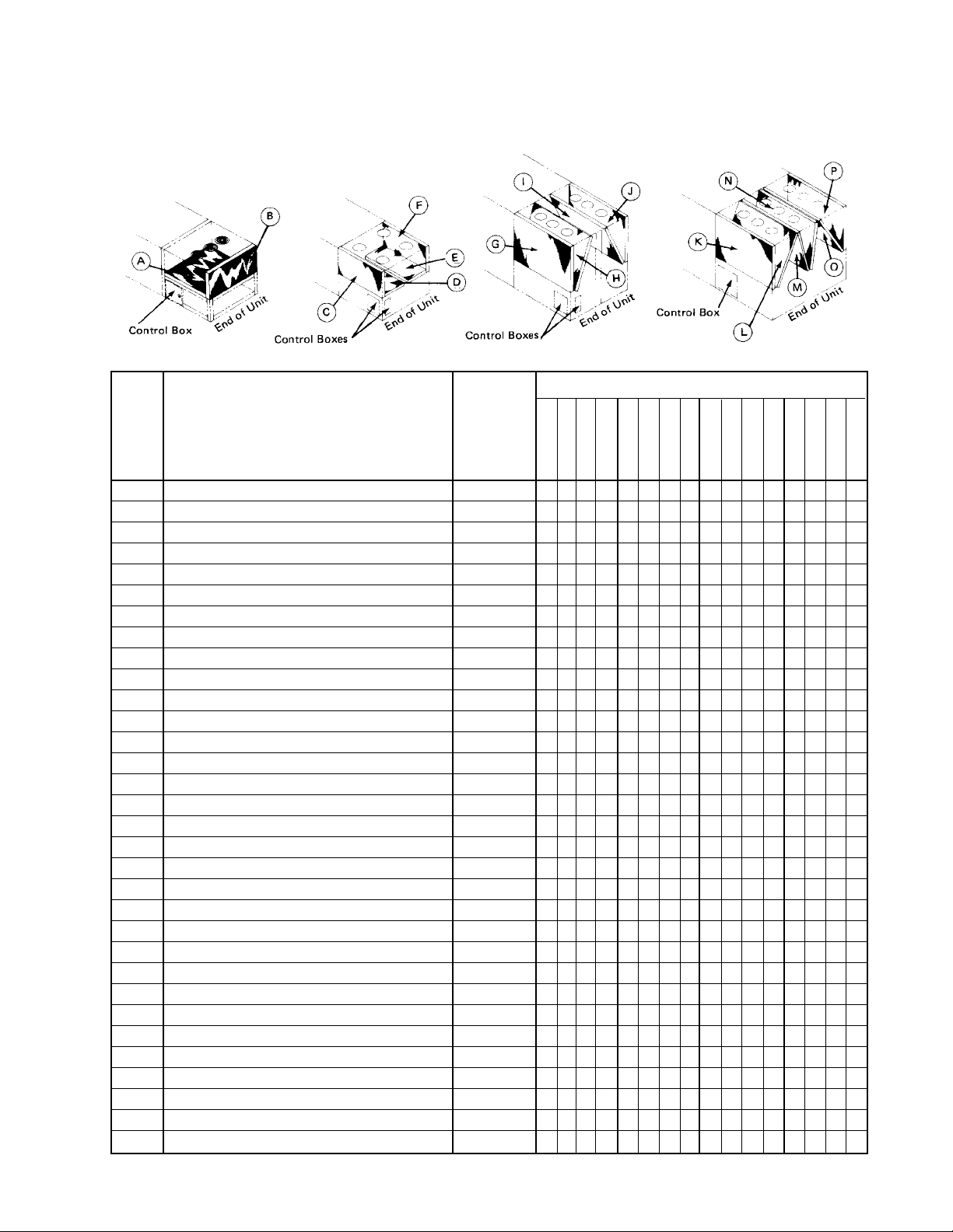
Condenser Coil Orientation
018B-030B 036B-040B 041B-071B 080B-100B
Coils
Condensing Coils
RPS/RFS Model Number - Pieces Per Unit
Ref.
Letter
A 3 CZ 1602 - 42.50 x 90.00 033498600 1 1
A 3 CZ 1203 - 42.50 x 90.00 033499200 1 1
B 3 CZ 1602 - 25.00 x 90.00 033498500 1 1
B 3 CZ 1203 - 25.00 x 90.00 033499100 1 1
C 3 CZ 1602 - 25.00 x 90.00 032007300 1 1
D 3 CZ 1602 - 25.00 x 90.00 032008200 1
D 3 CZ 1602 - 42.50 x 90.00 032007200 1
E 3 CZ 1602 - 25.00 x 90.00 032008300 1
E 3 CZ 1602 - 42.50 x 90.00 032007100 1
F 3 CZ 1602 - 25.00 x 90.00 032007400 1 1
G 3 CZ 1602 - 42.50 x 90.00 030158300 1
G 3 CZ 1602 - 42.50 x 90.00 030158200 1 1 1
G 3 CZ 1203 - 42.50 x 90.00 030156800 1 1
H 3 CZ 1602 - 25.00 x 90.00 030158000 1
H 3 CZ 1602 - 42.50 x 90.00 030158100 1 1 1
H 3 CZ 1203 - 42.50 x 90.00 030156700 1 1
I 3 CZ 1602 - 25.00 x 90.00 030157900 1 1
I 3 CZ 1602 - 42.50 x 90.00 030158600 1 1
I 3 CZ 1203 - 42.50 x 90.00 030156900 1 1
J 3 CZ 1602 - 42.50 x 90.00 030158400 1 1
J 3 CZ 1602 - 42.50 x 90.00 030158500 1 1
J 3 CZ 1203 - 42.50 x 90.00 030157000 1 1
K 3 CZ 1602 - 42.50 x 90.00 030158200 1 1 1
K 3 CZ 1203 - 42.50 x 90.00 030156800 1
L 3 CZ 1602 - 42.50 x 90.00 030158100 1 1 1
L 3 CZ 1203 - 42.50 x 90.00 030156700 1
M 3 CZ 1602 - 42.50 x 90.00 030158600 1 1 1 1
N 3 CZ 1602 - 42.50 x 90.00 030158500 1 1 1 1
O 3 CZ 1602 - 42.50 x 90.00 030158600 1 1 1
O 3 CZ 1203 - 42.50 x 90.00 030156900 1
P 3 CZ 1602 - 42.50 x 90.00 030158500 1 1 1
P 3 CZ 1203 - 42.50 x 90.00 030157000 1
Applied Rooftop; R*S Series / Vintage B Rev. W 08/12 RPL 047654300 / Page 24
Part Description
Part
Number
018B
020B
025B
030B
036B
040B
041B
051B
060B
070B
061B
071B
080B
081B
090B
100B
Page 25
Coils
Direct Expansion Evaporator Coils
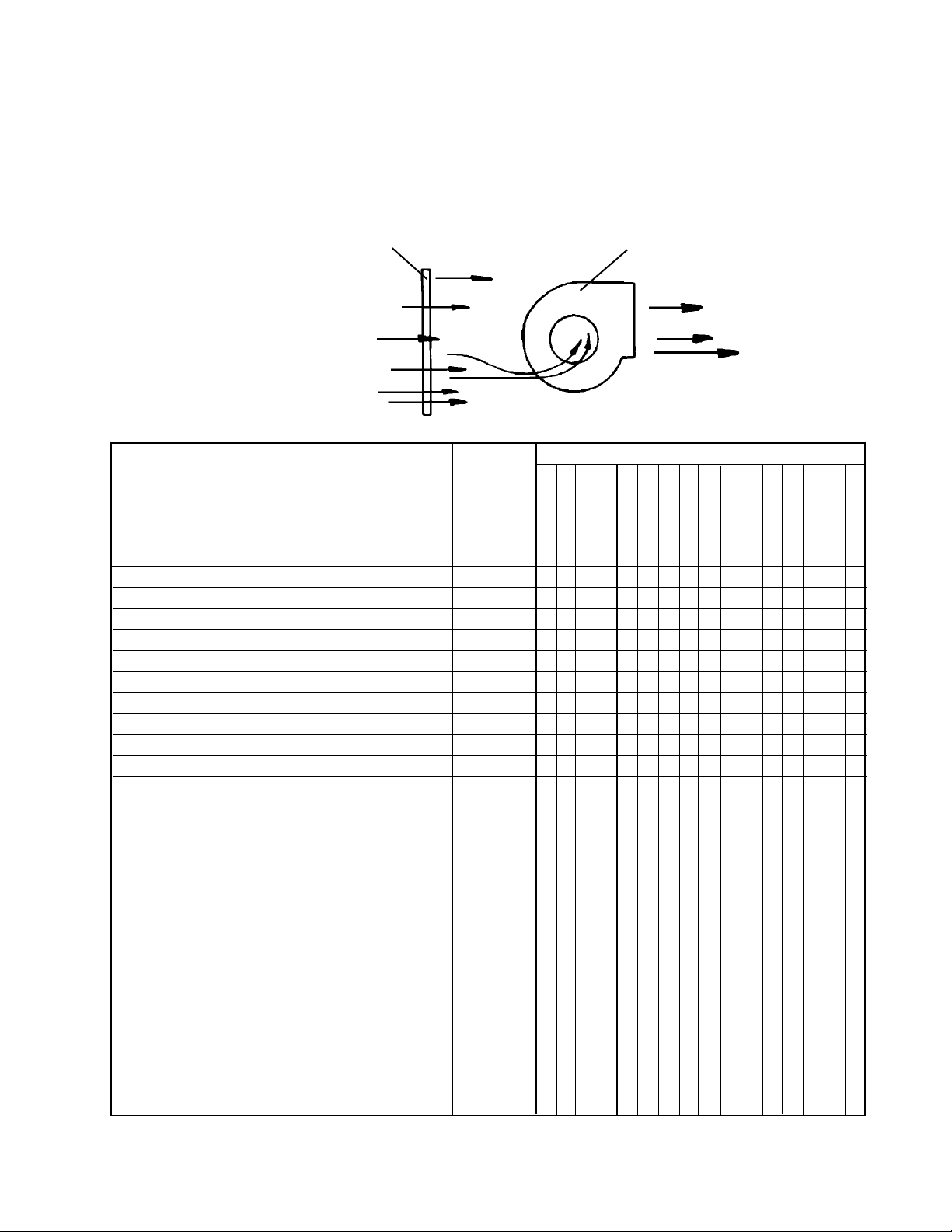
Single Draw-through Evaporator Coil / Unit Sizes 018B-030B, 82.00”
Single Draw-through Evaporator Coil
SINGLE DRAW-THROUGH
EVAPORATOR COIL
AIR FLOW
Model Number - Pieces Per Unit
Part Description
5 EZ 1202 - 33.00 x 82.00 2 Row (Before 11/92) 033228600 1 1
5 EZ 0803 - 33.00 x 82.00 3 Row (Before 11/92) 033228500 1 1
5 EZ 0804 - 33.00 x 82.00 4 Row (Before 11/92) 033228400 1 1
5 EZ 0805 - 33.00 x 82.00 5 Row (Before 11/92) 033228300 1 1
5 EZ 0803 - 33.00 x 82.00 3 Row* 058394301 1 1
5 EZ 1003 - 33.00 x 82.00 3 Row* 058394302 1 1
5 EZ 1203 - 33.00 x 82.00 3 Row* 058394303 1 1
5 EZ 0804 - 33.00 x 82.00 4 Row* 058394304 1 1
5 EZ 1004 - 33.00 x 82.00 4 Row* 058394305 1 1
5 EZ 1204 - 33.00 x 82.00 4 Row* 058394306 1 1
5 EZ 0805 - 33.00 x 82.00 5 Row* 058394307 1 1
5 EZ 1005 - 33.00 x 82.00 5 Row* 058394308 1 1
5 EZ 1205 - 33.00 x 82.00 5 Row* 058394309 1 1
5 EZ 1202 - 48.00 x 82.00 2 Row (Before 11/92) 033454700 1 1
5 EZ 0803 - 48.00 x 82.00 3 Row (Before 11/92) 033454800 1 1
5 EZ 0804 - 48.00 x 82.00 4 Row (Before 11/92) 033454900 1 1
5 EZ 0805 - 48.00 x 82.00 5 Row (Before 11/92) 033455000 1 1
5 EZ 0803 - 48.00 x 82.00 3 Row* 058394311 1 1
5 EZ 1003 - 48.00 x 82.00 3 Row* 058394312 1 1
5 EZ 1203 - 48.00 x 82.00 3 Row* 058394313 1 1
5 EZ 0804 - 48.00 x 82.00 4 Row* 058394314 1 1
5 EZ 1004 - 48.00 x 82.00 4 Row* 058394315 1 1
5 EZ 1204 - 48.00 x 82.00 4 Row* 058394316 1 1
5 EZ 0805 - 48.00 x 82.00 5 Row* 058394317 1 1
5 EZ 1005 - 48.00 x 82.00 5 Row* 058394318 1 1
5 EZ 1205 - 48.00 x 82.00 5 Row* 058394319 1 1
* Used with sloped drain pan, beginning approx. 11/92.
Part
Number
018B
020B
025B
030B
SUPPLY AIR FAN
036B
040B
041B
051B
060B
070B
061B
071B
080B
081B
090B
100B
Applied Rooftop; R*S Series / Vintage B Rev. W 08/12 RPL 047654300 / Page 25
Page 26
Coils
Direct Expansion Evaporator Coils
Single Blow-through Evaporator Coil / Unit Sizes 036B-040B / 82.00”
Single Blow-through Evaporator Coil
SUPPLY AIR FAN
Part Description
Single Blow-through Evaporator Coil (Fig. 8B)
5 EZ 0803 - 48.00 x 82.00 3 Row (Before 11/92) 037268200 1
5 EZ 0804 - 48.00 x 82.00 4 Row (Before 11/92) 037268300 1
5 EZ 0805 - 48.00 x 82.00 5 Row (Before 11/92) 037268400 1
5 EZ 0803 - 48.00 x 82.00 3 Row* 058394321 1
5 EZ 1003 - 48.00 x 82.00 3 Row* 058394322 1
5 EZ 1203 - 48.00 x 82.00 3 Row* 058394323 1
5 EZ 0804 - 48.00 x 82.00 4 Row* 058394324 1
5 EZ 1004 - 48.00 x 82.00 4 Row* 058394325 1
5 EZ 1204 - 48.00 x 82.00 4 Row* 058394326 1
5 EZ 0805 - 48.00 x 82.00 5 Row* 058394327 1
5 EZ 1005 - 48.00 x 82.00 5 Row* 058394328 1
5 EZ 1205 - 48.00 x 82.00 5 Row* 058394329 1
5 EZ 0803 - 48.00 x 82.00 3 Row (Before 11/92) 031561200 1
5 EZ 0804 - 48.00 x 82.00 4 Row (Before 11/92) 031561400 1
5 EZ 0805 - 48.00 x 82.00 5 Row (Before 11/92) 031561600 1
5 EZ 0803 - 48.00 x 82.00 3 Row* 058394331 1
5 EZ 1003 - 48.00 x 82.00 3 Row* 058394332 1
5 EZ 1203 - 48.00 x 82.00 3 Row* 058394333 1
5 EZ 0804 - 48.00 x 82.00 4 Row* 058394334 1
5 EZ 1004 - 48.00 x 82.00 4 Row* 058394335 1
5 EZ 1204 - 48.00 x 82.00 4 Row* 058394336 1
5 EZ 0805 - 48.00 x 82.00 5 Row* 058394337 1
5 EZ 1005 - 48.00 x 82.00 5 Row* 058394338 1
5 EZ 1205 - 48.00 x 82.00 5 Row* 058394339 1
* Used with sloped drain pans, beginning approx. 11/92.
AIR FLOW
Part
Number
018B
020B
SINGLE BLOW-THROUGH
EVAPORATOR COIL
Model Number - Pieces Per Unit
025B
030B
036B
040B
041B
051B
060B
070B
061B
071B
080B
081B
090B
100B
Applied Rooftop; R*S Series / Vintage B Rev. W 08/12 RPL 047654300 / Page 26
Page 27
Coils
Direct Expansion Evaporator Coils
Single Blow-through Evaporator Coil / Unit Sizes 041B-100B / 82.00’’
Model Number - Pieces Per Unit
Part
Number
018B
020B
025B
030B
036B
040B
041B
051B
060B
070B
061B
Part Description
Single Blow-through Evap. Coil, (Fig. 8B), Cont’d.
5 EZ 0803 - 54.00 x 82.00 3 Row 031484200 1
5 EZ 0804 - 54.00 x 82.00 4 Row 031484400 1
5 EZ 0805 - 54.00 x 82.00 5 Row 031484700 1
5 EZ 0803 - 66.00 x 82.00 3 Row 031484100 1
5 EZ 0804 - 66.00 x 82.00 4 Row 031484500 1
5 EZ 0805 - 66.00 x 82.00 5 Row 031484600 1
5 EZ 0803 - 66.00 x 82.00 3 Row 031290100 1 1
5 EZ 0804 - 66.00 x 82.00 4 Row 031484300 1 1
5 EZ 0805 - 66.00 x 82.00 5 Row 047110500 1 1
5 EZ 0803 - 90.00 x 82.00 3 Row 031655600 1 1
5 EZ 0804 - 90.00 x 82.00 4 Row 031655800 1 1
5 EZ 0805 - 90.00 x 82.00 5 Row 031655700 1 1
5 EZ 0803 - 90.00 x 82.00 3 Row 031657300 1
5 EZ 0804 - 90.00 x 82.00 4 Row 031657400 1
5 EZ 0805 - 90.00 x 82.00 5 Row 031657500 1
071B
080B
081B
090B
100B
Applied Rooftop; R*S Series / Vintage B Rev. W 08/12 RPL 047654300 / Page 27
Page 28

Coils
Direct Expansion Evaporator Coils
Dual Blow-through Evaporator Coil / Unit Sizes 081B-100B / 82.00’’
Dual Blow-through Evaporator Coil
SUPPLY AIR FAN
AIR FLOW
DUAL BLOW-THROUGH
54.00” EVAPORATOR COIL
Model Number - Pieces Per Unit
Part Description
Dual Blow-through Evaporator Coil (Fig. 8C)
5 EZ 0803 - 54.00 x 82.00 3 Row 031267800 1 1 1
5 EZ 0804 - 54.00 x 82.00 4 Row 031267900 1 1 1
5 EZ 0805 - 54.00 x 82.00 5 Row 031268000 1 1 1
5 EZ 0803 - 66.00 x 82.00 3 Row 031268100 1 1 1
5 EZ 0804 - 66.00 x 82.00 4 Row 031268200 1 1 1
5 EZ 0805 - 66.00 x 82.00 5 Row 031268300 1 1 1
Part
Number
018B
020B
025B
030B
036B
DUAL BLOW-THROUGH
66.00” EVAPORATOR COIL
040B
041B
051B
060B
070B
061B
071B
080B
081B
090B
100B
Applied Rooftop; R*S Series / Vintage B Rev. W 08/12 RPL 047654300 / Page 28
Page 29

Upper Main Control Panel: Non MicroTech (Code 20= 30, 31)
Unit Controller Diagrams - All sizes
Applied Rooftop; R*S Series / Vintage B Rev. W 08/12 RPL 047654300 / Page 29
Page 30

Upper Main Control Panel: Non MicroTech (Code 20= 30, 31)
Diagram and Components - All sizes
Upper Main Control Panel
NOTE: Most common locations of controls are shown. Actual location of controls may vary with unit size & unit options.
UNIT CONTROLLER
Schematic*
Symbol
R16 Fan Relay 24V SPDT 061019403 1
R17 Economizer Relay 24V SPDT 061019403 1
R18 Cool Relay No. 1 24V SPDT 061019403 1
R19 Cool Relay No. 2 24V 3PDT 030811400 1
R20 Gas & Oil Heat Relay 24V DPDT 029858800 1
R20 Electric Heat Relay 120V DPDT 019643000 1
R20 Electric Heat Relay 24V DPDT 016508002 1
R20 Steam & Hot Water 24V DPDT 016508002 1
R21 Electric Heat Relay 24V SPDT 061019403 1
R22 Cooling Fan Interlock 120V 3PDT 073340001 1
R23 Heat Fan Interlock 120V DPDT 044465500 1
*NOTE: Schematic symbols appear on unit wiring diagrams and components are marked with them at time of manufacture.
Applied Rooftop; R*S Series / Vintage B Rev. W 08/12 RPL 047654300 / Page 30
General Function
Part Description
Coil Volt.
No. of Poles
Part
Number
Quantity Per Unit
(When Option Exists)
Page 31

Upper Main Control Panel: Non MicroTech (Code 20= 30, 31)
All Sizes, Continued
Schematic*
Symbol
R24 Cool Alarm Coil Voltage; 120V SPDT 032508101 1
R25 Cool Alarm Coil Voltage, 120V SPDT 032508101 1
R26 Night Setback Coil Voltage, 24V 3PDT 030811400 1
R27 Electric Heat Relay Coil Voltage, 24V SPDT 061019403 1
R37 Smoke Trip Coil Voltage, 120V 3PDT 073340001 1
R41 Duct High Limit Coil Voltage, 120V SPDT 032508101 1
R42 Floating Pressure Control Coil Voltage, 120V SPDT 032508101 1
R43 Cool Relay Coil Voltage, 24V SPDT 061019403 1
R44 Cool Alarm Coil Voltage, 120V SPDT 032508101 1
TERMINAL BLOCKS
TB6 Heating Circuits 7 Pole 015998107 1
TB7 Main Control, 120V 8 Pole 015998108 1
TB7 Main Control, 120V 14 Pole 015998114 1
TB7 Main Control, 120V 28 Pole 015998128 1
TB7 Main Control, 120V 30 Pole 015998130 1
TB9 24V Factory Connection 14 Pole 015998114 1
TB10 VAV Float Controls 7 Pole 015998107 1
NB Neutral Bar 7 Pole 037530800 1
NB Neutral Bar 16 Pole 037530700 1
THERMOSTATS
TC5 125o Firestat, Units with Cooling Only 027672500 1
TC5 225o Firestat, Units with Heating 028395300 1
TC6 Summer-Winter Changeover (Compr. Lockout) 023796401 1
TRANSFORMERS
T2 24 Volt Control Circuit, 120-27V, .045 KVA 029948300 1
T3 Economizer, 120-27V, .045 KVA 029948300 1
T6 Variable Air Volume Control, 120-25V, .020 KVA 030886400 1
SWITCHES
S1 System Switch SPST-Use on all units except with gas or oil heat 001355000 1
S1 System Switch DPST-Use on all units with oil or gas heat 018446400 1
HS Heat Switch SPST 001355000 1
None Test Switch with Leads, Units with W7100 (DAC1) 042236200 1
POTENTIOMETER, UNIT MOUNTED
OA Outside Air Potentiometer (Units with Electric Heat) 026116600 1
OA Outside Air Potentiometer (Units without Electric Heat) 043212800 1
None Knob for Potentiometer 029024400 1
FUSE
F1 Fuse Holder 029552200 1
F1 Fuse, 15 Amp 029552300 1
F1 Fuse, 6 Amp 036559100 1
*NOTE: Schematic symbols appear on unit wiring diagrams and components are marked with them at time of manufacture.
General Function
Part Description
No. of Poles
Part
Number
Quantity Per Unit
(When Option Exists)
Applied Rooftop; R*S Series / Vintage B Rev. W 08/12 RPL 047654300 / Page 31
Page 32

Upper Main Control Panel: Non MicroTech (Code 20= 30, 31)
Components - All Sizes, Continued
Schematic*
Symbol
INDICATOR LIGHT
LT1 Duct High Limit Neon Light, Red 016508303 1
RECEPTACLE
RECP 120V Service Receptacle 025283700 1
CONTROLLERS
CP1 W973B Solid-State Central Processor 041760200 1 1
NSB W974A Night Setback Module 037529600 1
W7100A Discharge Air Controller, RPS/RFS units only
(includes 600 ohm resistor) 041772500 1
W7100D Discharge Air Controller, RHS/RWS units only
(includes 1000 ohm resistor) 042643600 1
DAC1 Resistor, 200 ohm, 2 stage control 044690102 1
DAC1
DAC1 Resistor, 301 ohm, 3 stage control 044690103 1
DAC1 Resistor, 402 ohm, 4 stage control 044690104 1
DAC1 Resistor, 499 ohm, 5 stage control 044690105 1
DAC1 Resistor, 600 ohm, 6 stage control 044690106 1
DAC1 Resistor, 806 ohm, 8 stage control 044690108 1
DAC1 Resistor, 909 ohm, 9 stage control 044690109 1
Resistor (W7100D Only) 1000 ohm 044690110 1
Resistor Kit (includes all of above resistors) 044691300 1
DAS1 W7101A Satellite Sequencer, RPS/RFS Units w/more than 6 stages 042226900 1
EPC Vanetrol, Electronic Pressure Controller 037524300 1
OBSOLETE CONTROLLERS (Not Shown) Consult Daikin McQuay Parts for availability.
SC Step Controller, 6 stage, Honeywell S984-P-1004 031855700 1
SC Step Controller, 10 stage, Honeywell S984-J-1034 033838200 1
PTC2 Proportional Temp. Control, Solid-state, Pressure-Johnson PC-4000-2 031775202 1
*NOTE: Schematic symbols appear on unit wiring diagrams and components are marked with them at time of manufacture.
1
When a unit has hydronic heat (C03= W or S) and a modulating valve (C16=****M) the CP1 part number is: 037529500.
Part Description
Part
Number
Quantity
Per Unit
(When Option
Exists)
Applied Rooftop; R*S Series / Vintage B Rev. W 08/12 RPL 047654300 / Page 32
Page 33

Upper Main Control Panel: MicroTech (Code 20= 1M, 2M, 4M)
Diagrams - 018- 040
Upper Main Control Panel
NOTE: Most common locations of controls are shown. Actual location of controls may vary with unit size & unit options.
Not all possible components are shown in the below diagrams. MicroTech controls were mostly used in sizes 018- 040
although some larger units were made as specials. Lower Main Control Panel components do not change from NonMicroTech equipped units.
1995 Units and Before
T2
Keypad
Display
MCB1
TB6
P
M
1
T
B
1
0
R6
R5
R24
NB1
T3
R26
R20
TB3TB4
DB1
TB5
TB5
TB2
OBA
SB1
TB8
OBB
Keypad
Display
MCB1
See Lower Main Control Section
1996 Units and Later
T2
P
M
1
R24
T3
R26
R20
NB1
See Lower Main Control Section
R29
SPS1
SPS2
ADI
OBA
SB1
DHL
OBB
Applied Rooftop; R*S Series / Vintage B Rev. W 08/12 RPL 047654300 / Page 33
Page 34

Upper Main Control Panel: MicroTech (Code 20= 1M, 2M, 4M)
Components - 018- 040
Sch.* Part Part
Sym. Description Number Qty.
Switches
S1 Toggle Switch- Control: Units with Gas Heat (C04= A) 018446400 1
Toggle Switch- Control: Units without Gas Heat (C04= E, W, S, Y, X) 001355000 1
S6 Switch- VIV Units (C15= 2) 047357306 1
HS1 Switch- Electric Heat Shutdown (C04= E) 001355000 1
PS3 Toggle Switch- Unit Pumpdown 001355000 1
Fusing
F1 Fuse- Control Circuit- 15A/250V 025954700 1
Fuse Holder for F1 018690600 1
F3 Fuse- Gas Heat Burner Motor 025860505 1
Fuse Holder for F3 023780201 1
Receptacle
REC1 Receptacle- Standard, 1P/3W/15A 025283700 1
Receptacle- Duplex Feed thru GF1, 2P/3W/15A 039003100 1
Receptacle- Duplex GF1, 2P/3W/15A 039003600 1
Receptacle- Duplex Feed thru GF1, 2P/3W/20A 066402701 1
Terminal Blocks
TB1 Terminal Block- Service Recepticle Circuit, 115V Field, 3 Pole 022431203 1
TB2 Terminal Block- Field
C12= 1M- (14 pole portion) 022431214 1
C12= 1M- (24 pole portion) 022431224 1
C12= 2M, 4M, 5M 022431230 2
TB5 Terminal Block- Control 015998130 1
TB6 Terminal Block- Control 015998120 1
TB7 Terminal Block- Factory 015998130 1
TB8 Terminal Block- Factory 015998114 1
TB10 Terminal Block- Heating 015998109 1
NB1, 2 Neutral Block, 7 Pole 037530800 2
Transformers
T2 Transformer- Unit 060630801 1
T3 Transformer- Controller 046738114 1
T4 Transformer- Power Relief Dampers
until 5/02 046738109 1
5/02 & later 060614101 1
Rectifier- T4 111059401 1
Terminal Block- T4 & Rectifier 065499806 1
T5 Transformer- Specials 060630801 1
*NOTE: Schematic symbols appear on unit wiring diagrams and components are marked with them at time of manufacture.
Applied Rooftop; R*S Series / Vintage B Rev. W 08/12 RPL 047654300 / Page 34
Page 35

Upper Main Control Panel: MicroTech (Code 20= 1M, 2M, 4M)
Components - 018- 040, Continued
Sch. Part Part
Sym. Description Number Qty.
Relays
R20 Relay- Gas Heat On/Off 019643000 1
R24 Relay- Gas Heat Alarm 032508101 1
R26 Relay- Occupied/Unoccupied 019643000 1
R27 Relay- Powered Relief Dampers 019643000 1
R28 Relay- Isolation Damper 032508101 1
R29 Relay- Final Filter 026213000 1
Transducer and Pressure Controls
SPS1 Sensor- Duct Static Pressure (C24 Digit 3= 1, 2, 3) 049545005 1
SPS2 Sensor- Duct Static Pressure (C24 Digit 3= 2) 049545005 1
Sensor- Building Static Pressure (C24 Digit 3= 3, 4) 049545006 1
DHL Switch- Duct Hi- Limit 065493801 1
Fitting for DHL 049763002 1
Main MicroTech Controller and Associated Boards
MCB1 Microprocessor (must be programmed- requires unit GO or Serial No.) 065487306 1
Fuse- MCB1 065822001 1
Keypad Keypad/Display Assembly 065497201 1
Ribbon Cable- MCB to Keypad 065499702 1
ADI ADI Board 1 065816005 1
DB1 Daughter Board 1 049545501 1
Fuse, DB1 065829601 1
Ribbon Cable- MCB to DB1 049265103 1
OBA Output Board- 16 position 066542201 1
Ribbon Cable- MCB to OBA 049265204 1
OBB Output Board- 4 position- Cooling 066542203 1
OBB Output Board- 8 position- Cooling 066542202 1
OBC Output Board- 8 position- Heating 066542202 1
OB_ _ Output Board Relay
Standard Relay 049265601
Small Relay 073202501
SB1 Cooling Staging Board
4 or 6 stages cooling and no unloaders 065499001 1
6 stages cooling and 2 unloaders per circuit 065499002 1
4 - 8 stages cooling and 1 unloader per circuit 065499003 1
SB2 Heating Staging Board- 4 to 8 stages of Heat 065499001 1
Room Sensors
Sensor #1- Standard VAV 066540401 1
Sensor #2- Enhanced VAV (includes tenant override) 066540402 1
Sensor #9- Standard CAV 066540409 1
1
Units built prior to 1995 used a Daughter Board (DB1). In 1996, the Daughter board was replaced with an ADI board.
2
Quantity varies depending on options.
3
Used on VAV units (C12= 2M or 4M) with 4 stages of cooling (C42= 4). CAV units (C12= 1M or 5M) units have all cooling control
directly from MCB to OBA. Ribbon cable connecting OBB to SB1 is p/n 065499501.
4
Used on VAV units (C12= 2M or 4M) with 6 or 8 stages of cooling (C42= 6 or 8). CAV units (C12= 1M or 5M) units have all cooling
control directly from MCB to OBA. Ribbon cable connecting OBB to SB1 is p/n 065499501.
5
Used on CAV units (C12= 1M or 5M) with more than 4 stages of electrical heat. Ribbon cable connecting OBC to SB2 is p/n
065499501.
6
Prior to 1/92 use p/n 058899372 for VAV and p/n 065824701 for CAV.
3
4
5
2
2
5
6
6
6
Applied Rooftop; R*S Series / Vintage B Rev. W 08/12 RPL 047654300 / Page 35
Page 36

Lower Main Control Panel
Component Location Diagram - All Sizes
Applied Rooftop; R*S Series / Vintage B Rev. W 08/12 RPL 047654300 / Page 36
Page 37

Lower Main Control Panel
Components - All Sizes
Schematic*
Symbol
FUSE, GAS/OIL BURNER MOTOR
F2
Fuse - 20 Amp; Gas/Oil Burner Motor 025860507 1
FUSEBLOCK, SUPPLY AIR FAN
1 - 7.5 208 Across the Line 30A @ 250V 023780204 1
10 & 15 208 Across the Line 60A @ 250V 023780209 1
20 & 25 208 Across the Line 100A @ 250V 023780213 1
30 208 Across the Line 60A @ 250V 023780209 1
40 - 60 208 Across the Line 100A @ 250V 023780213 1
75 & 100 208 Across the Line 200A @ 250V 023780218 1
1 - 7.5 230 Across the Line 30A @ 250V 023780204 1
10 & 15 230 Across the Line 60A @ 250V 023780209 1
20 - 30 230 Across the Line 100A @ 250V 023780213 1
40 230 Across the Line 60A @ 250V 023780209 1
50 & 60 230 Across the Line 100A @ 250V 023780213 1
75 & 100 230 Across the Line 200A @ 250V 023780218 1
1 - 15 380 or 460 Across the Line 30A @ 600V 023780205 1
20 - 40 380 or 460 Across the Line 60A @ 600V 023780210 1
FB9
50 & 60 380 or 460 Across the Line 100A @ 600V 023780212 1
75 & 100 380 or 460 Across the Line 200A @ 600V 023780215 1
15 208 Part Winding 30A @ 250V 023780204 1
20 - 30 208 Part Winding 60A @ 250V 023780209 1
40 - 60 208 Part Winding 100A @ 250V 023780213 1
75 & 100 208 Part Winding 200A @ 250V 023780218 1
15 230 Part Winding 30A @ 250V 023780204 1
20 - 40 230 Part Winding 60A @ 250V 023780209 1
50 & 60 230 Part Winding 100A @ 250V 023780213 1
75 & 100 230 Part Winding 200A @ 250V 023780218 1
30 208 Across the Line 60A @ 250V 023780209 1
40 - 60 208 Across the Line 100A @ 250V 023780213 1
75 & 100 208 Across the Line 200A @ 250V 023780218 1
40 230 Across the Line 60A @ 250V 023780209 1
50 & 60 230 Across the Line 100A @ 250V 023780213 1
75 & 100 230 Across the Line 200A @ 250V 023780218 1
15 208 Part Winding 30A @ 250V 023780204 1
20 - 30 208 Part Winding 60A @ 250V 023780209 1
FB10
40 - 60 208 Part Winding 100A @ 250V 023780213 1
75 & 100 208 Part Winding 200A @ 250V 023780218 1
15 230 Part Winding 30A @ 250V 023780204 1
20 - 40 230 Part Winding 60A @ 250V 023780209 1
50 & 60 230 Part Winding 100A @ 250V 023780213 1
75 & 100 230 Part Winding 200A @ 250V 023780218 1
* NOTE: Schematic symbols appear on unit wiring diagrams and components are marked with them at time of manufacture.
Fuseblock; Gas/Oil Burner Motor 023780201 1
Fan HP
Fan Voltage
Part Description
Fan Starting
Fuseblock Rating
Part Number
Quantity
Applied Rooftop; R*S Series / Vintage B Rev. W 08/12 RPL 047654300 / Page 37
Page 38

Lower Main Control Panel
Components - Continued
Part Description
Schematic*
Symbol
FUSEBLOCK, RETURN AIR FAN
1 - 7.5 208 Across the Line 30A @ 250V 023780204 1
10 & 15 208 Across the Line 60A @ 250V 023780209 1
20 & 25 208 Across the Line 100A @ 250V 023780213 1
30 208 Across the Line 60A @ 250V 023780209 1
40 - 60 208 Across the Line 100A @ 250V 023780213 1
1 - 7.5 230 Across the Line 30A @ 250V 023780204 1
10 & 15 230 Across the Line 60A @ 250V 023780209 1
20 - 30 230 Across the Line 100A @ 250V 023780213 1
40 230 Across the Line 60A @ 250V 023780209 1
FB11
50 & 60 230 Across the Line 100A @ 250V 023780213 1
1 - 15 380 or 460 Across the Line 30A @ 600V 023780205 1
20 - 30 380 or 460 Across the Line 60A @ 600V 023780210 1
40 - 60 380 or 460 Across the Line 100A @ 600V 023780212 1
15 208 Part Winding 30A @ 250V 023780204 1
20 - 30 208 Part Winding 60A @ 250V 023780209 1
40 - 60 208 Part Winding 100A @ 250V 023780213 1
15 230 Part Winding 30A @ 250V 023780204 1
20 - 40 230 Part Winding 60A @ 250V 023780209 1
50 & 60 230 Part Winding 100A @ 250V 023780213 1
30 208 Across the Line 60A @ 250V 023780209 1
40 - 60 208 Across the Line 100A @ 250V 023780213 1
40 230 Across the Line 60A @ 250V 023780209 1
50 & 60 230 Across the Line 100A @ 250V 023780213 1
15 208 Part Winding 30A @ 250V 023780204 1
FB12
20 - 30 208 Part Winding 60A @ 250V 023780209 1
40 - 60 208 Part Winding 100A @ 250V 023780213 1
15 230 Part Winding 30A @ 250V 023780204 1
30 - 40 230 Part Winding 60A @ 250V 023780209 1
50 & 60 230 Part Winding 100A @ 250V 023780213 1
FUSEBLOCK, MAIN CONTROL TRANSFORMER
Unit Voltage Fuseblock Rating
FB13
208 or 230 30A @ 250V 023780202 1
380 or 460 30A @ 600V 023780203 1
* NOTE: Schematic symbols appear on unit wiring diagrams and components are marked with them at time of manufacture.
Fan
Horsepower
Fan
Voltage
Fan
Starting
Fuseblock
Rating
Part Number
Part Number Quantity
Quantity
Applied Rooftop; R*S Series / Vintage B Rev. W 08/12 RPL 047654300 / Page 38
Page 39

Lower Main Control Panel
Components - Continued
Schematic*
Symbol
CONTACTOR, SUPPLY AIR FAN
1 - 5 208 Across the Line 25 AMP 027514401 1
7.5 208 Across the Line 30 AMP 027514402 1
10 208 Across the Line 40 AMP 027514403 1
15 208 Across the Line 50 AMP 027514404 1
20 208 Across the Line 75 AMP 027514406 1
25 208 Across the Line 90 AMP 027514407 1
30 208 Across the Line 50 AMP 027514404 1
40 208 Across the Line/Part Winding 75 AMP 027514406 1
50, 60 208 Across the Line/Part Winding 90 AMP 027514407 1
75 208 Across the Line/Part Winding 120 AMP 072288701 1
100 208 Across the Line/Part Winding 200 AMP 027514409 1
15 208 Part Winding 25 AMP 027514401 1
20, 25 208 Part Winding 40 AMP 027514403 1
30 208 Part Winding 50 AMP 027514404 1
1 - 7.5 230 Across the Line 25 AMP 027514401 1
10 230 Across the Line 30 AMP 027514402 1
15 230 Across the Line 50 AMP 027514404 1
20 230 Across the Line 60 AMP 027514405 1
M20
25 230 Across the Line 75 AMP 027514406 1
30 230 Across the Line 90 AMP 027514407 1
40 230 Across the Line 60 AMP 027514405 1
50 230 Across the Line 75 AMP 027514406 1
60 230 Across the Line 90 AMP 027514407 1
75 230 Across the Line/Part Winding 120 AMP 072288701 1
100 230 Across the Line/Part Winding 200 AMP 027514409 1
15 230 Part Winding 25 AMP 027514401 1
20 230 Part Winding 30 AMP 027514402 1
25 230 Part Winding 40 AMP 027514403 1
30, 40 230 Part Winding 50 AMP 027514404 1
50, 60 230 Part Winding 75 AMP 027514406 1
1-15 380,460 Across the Line 25 AMP 027514401 1
20 380,460 Across the Line 30 AMP 027514402 1
25 380,460 Across the Line 40 AMP 027514403 1
30 380,460 Across the Line 50 AMP 027514404 1
40 380,460 Across the Line 60 AMP 027514405 1
50 380,460 Across the Line 75 AMP 027514406 1
60 380,460 Across the Line 90 AMP 027514407 1
75 380,460 Across the Line 100 AMP 072288701 1
100 380,460 Across the Line 200 AMP 027514409 1
* NOTE: Schematic symbols appear on unit wiring diagrams and components are marked with them at time of manufacture.
Fan
Horsepower
Fan
Voltage
Part Description
Fan
Starting
Contactor Rating
(FLA)
Part Number
Quantity
Applied Rooftop; R*S Series / Vintage B Rev. W 08/12 RPL 047654300 / Page 39
Page 40

Lower Main Control Panel
Components - Continued
Part Description
Schematic*
Symbol
CONTACTOR, SUPPLY AIR FAN
30 208 Across the Line 50 AMP 027514104 1
40 208 Across the Line 75 AMP 027514106 1
50, 60 208 Across the Line 90 AMP 027514107 1
75 208 Across the Line 120 AMP 027514108 1
100 208 Across the Line 200 AMP 027514109 1
15 208 Part Winding 25 AMP 027514101 1
20, 25 208 Part Winding 40 AMP 027514103 1
30 208 Part Winding 50 AMP 027514104 1
40 208 Part Winding 75 AMP 027514106 1
50, 60 208 Part Winding 90 AMP 027514107 1
M21
75 208 Part Winding 120 AMP 027514108 1
100 208 Part Winding 200 AMP 027514109 1
40 230 Across the Line 60 AMP 027514105 1
50 230 Across the Line 75 AMP 027514106 1
60 230 Across the Line 90 AMP 027514107 1
75 230 Across the Line 120 AMP 027514108 1
100 230 Across the Line 200 AMP 027514109 1
15 230 Part Winding 25 AMP 027514101 1
20 230 Part Winding 30 AMP 027514102 1
25 230 Part Winding 40 AMP 027514103 1
30, 40 230 Part Winding 50 AMP 027514104 1
50, 60 230 Part Winding 75 AMP 027514106 1
75 230 Part Winding 120 AMP 027514108 1
100 230 Part Winding 200 AMP 027514109 1
* NOTE: Schematic symbols appear on unit wiring diagrams and components are marked with them at time of manufacture.
Fan
Horsepower
Fan
Voltage
Fan
Starting
Contactor Rating
(FLA)
Part Number
Quantity
Applied Rooftop; R*S Series / Vintage B Rev. W 08/12 RPL 047654300 / Page 40
Page 41

Lower Main Control Panel
Components - Continued
Part Description
Schematic*
Symbol
CONTACTOR, RETURN AIR FAN
1-5 208 Across the Line 25 AMP 027514101 1
7.5 208 Across the Line 30 AMP 027514102 1
10 208 Across the Line 40 AMP 027514103 1
15 208 Across the Line 50 AMP 027514104 1
20 208 Across the Line 75 AMP 027514106 1
25 208 Across the Line 90 AMP 027514107 1
30 208 Across the Line 50 AMP 027514104 1
40 208 Across the Line 75 AMP 027514106 1
50, 60 208 Across the Line 90 AMP 027514107 1
15 208 Part Winding 25 AMP 027514101 1
20, 25 208 Part Winding 40 AMP 027514103 1
30 208 Part Winding 50 AMP 027514104 1
40 208 Part Winding 75 AMP 027514106 1
50, 60 208 Part Winding 90 AMP 027514107 1
M22
1-7.5 230 Across the Line 25 AMP 027514101 1
10 230 Across the Line 30 AMP 027514102 1
15 230 Across the Line 50 AMP 027514104 1
20 230 Across the Line 60 AMP 027514105 1
25 230 Across the Line 75 AMP 027514106 1
30 230 Across the Line 90 AMP 027514107 1
40 230 Across the Line 60 AMP 027514105 1
50 230 Across the Line 75 AMP 027514106 1
60 230 Across the Line 90 AMP 027514107 1
15 230 Part Winding 25 AMP 027514101 1
20 230 Part Winding 30 AMP 027514102 1
25 230 Part Winding 40 AMP 027514103 1
30, 40 230 Part Winding 50 AMP 027514104 1
50, 60 230 Part Winding 75 AMP 027514106 1
1-15 380,460 Across the Line 25 AMP 027514101 1
20 380,460 Across the Line 30 AMP 027514102 1
25 380,460 Across the Line 40 AMP 027514103 1
30 380,460 Across the Line 50 AMP 027514104 1
40 380,460 Across the Line 60 AMP 027514105 1
50 380,460 Across the Line 75 AMP 027514106 1
60 380,460 Across the Line 90 AMP 027514107 1
Fan
Horsepower
Fan
Voltage
Fan
Starting
Contactor Rating
(FLA)
Part Number
Quantity
* NOTE: Schematic symbols appear on unit wiring diagrams and components are marked with them at time of manufacture.
Applied Rooftop; R*S Series / Vintage B Rev. W 08/12 RPL 047654300 / Page 41
Page 42

Lower Main Control Panel
Components - Continued
Schematic*
Symbol
CONTACTOR, RETURN AIR FAN - PART OR DUAL WINDING
30 208 Across the Line 50 AMP 027514104 1
40 208 Across the Line 75 AMP 027514106 1
50, 60 208 Across the Line 90 AMP 027514107 1
75 208 Across the Line 120 AMP 027514108 1
100 208 Across the Line 200 AMP 027514109 1
15 208 Part Winding 25 AMP 027514101 1
20, 25 208 Part Winding 30 AMP 027514103 1
30 208 Part Winding 50 AMP 027514104 1
40 208 Part Winding 75 AMP 027514106 1
50, 60 208 Part Winding 90 AMP 027514107 1
M23
75 208 Part Winding 120 AMP 027514108 1
100 208 Part Winding 200 AMP 027514109 1
40 230 Across the Line 60 AMP 027514105 1
50 230 Across the Line 75 AMP 027514106 1
60 230 Across the Line 90 AMP 027514107 1
15 230 Part Winding 25 AMP 027514101 1
20 230 Part Winding 30 AMP 027514102 1
25 230 Part Winding 40 AMP 027514103 1
30, 40 230 Part Winding 50 AMP 027514104 1
40, 60 230 Part Winding 75 AMP 027514106 1
* NOTE: Schematic symbols appear on unit wiring diagrams and components are marked with them at time of manufacture.
Fan
Horsepower
Part Description
Fan
Voltage
Fan
Starting
Contactor Rating
(FLA)
Part Number
Quantity
Applied Rooftop; R*S Series / Vintage B Rev. W 08/12 RPL 047654300 / Page 42
Page 43

Lower Main Control Panel
Components - Continued
Part Description
Schematic*
Symbol
OVERLOAD RELAY & HEATER, SUPPLY & RETURN FAN
1 208 Across the Line 030189200 022977400
1 230 Across the Line 030189200 031450066
1 380, 460 Across the Line 030189200 031450020
1.5 208 Across the Line 030189200 026114400
1.5 230 Across the Line 030189200 031010100
1.5 380, 460 Across the Line 030189200 031450024
2 208 Across the Line 030189200 030192400
2 230 Across the Line 030189200 026114600
2 380, 460 Across the Line 030189200 026216000
3 208 Across the Line 030189200 023466900
3 230 Across the Line 030189200 023074700
3 380, 460 Across the Line 030189200 030733600
5 208 Across the Line 030189200 027401100
5 230 Across the Line 030189200 024688500
5 380, 460 Across the Line 030189200 030192400
7.5 208 Across the Line 030189300 023689100
7.5 230 Across the Line 030189200 026111700
OL1
7.5 380, 460 Across the Line 030189200 027401000
&
10 208 Across the Line 030189300 022773400
OL3
10 230 Across the Line 030189300 023252800
10 380, 460 Across the Line 030189200 024688500
15 208 Across the Line 030189400 025861600
15 208 Part Winding 030189200 023689100
15 230 Across the Line 030189400 022613000
15 230 Part Winding 030189200 026111700
15 380, 460 Across the Line 030189200 026111700
20 208 Across the Line 030189400 022613100
20 208 Part Winding 030189300 022773400
20 230 Across the Line 030189400 023074800
20 230 Part Winding 030189300 022773400
20 380, 460 Across the Line 030189300 023252800
25 208 Across the Line 030189400 023467200
25 208 Part Winding 030189300 023076000
25 230 Across the Line 030189400 022613100
25 230 Part Winding 030189300 023252800
25 380, 460 Across the Line 030189300 022773400
30 208 Across the Line,Part Winding 030189400 022613000
30 230 Part Winding 030189400 023467200
30 230 Across the Line 030189400 023076000
30 380, 460 Part Winding 030189204 023076000
Note: 3 heaters per overload relay. 1, 2 or 4 overload relays per unit. OL1 & OL2=Supply fan overloads. OL3 & OL4=Return fan overloads.
* NOTE: Schematic symbols appear on unit wiring diagrams and components are marked with them at time of manufacture.
Horsepower Overload Relay
Voltage
Fan Starting
Part Numbers
Heater
Applied Rooftop; R*S Series / Vintage B Rev. W 08/12 RPL 047654300 / Page 43
Page 44

Lower Main Control Panel
Components - Continued
Schematic*
Symbol
OVERLOAD RELAY & HEATER, SUPPLY & RETURN FAN
40 208 Across the Line/Part Winding 030189400 023074800
40 230 Across the Line/Part Winding 030189400 025861600
40 380,460 Across the Line 030189400 025861600
50 208 Across the Line/Part Winding 030189400 021858500
50 230 Across the Line/Part Winding 030189400 022613100
50 380,460 Across the Line 030189400 022613100
OL1
60 208 Across the Line/Part Winding 030189400 030192500
&
60 230 Across the Line/Part Winding 030189400 023467200
OL3
60 380,460 Across the Line 030189400 023467200
75 208 Across the Line/Part Winding 030189500 030192600
75 230 Across the Line/Part Winding 030189500 030192600
75 380,460 Across the Line 030189500 030192600
100 208 Across the Line/Part Winding 030189500 031450057
100 230 Across the Line/Part Winding 030189500 031450057
100 380,460 Across the Line 030189500 031450057
15 208 Part Winding 030189200 023689100
15 230 Part Winding 030189200 026111700
20 208 Part Winding 030189300 022773400
20 230 Part Winding 030189300 023252800
25 208 Part Winding 030189300 023076000
25 230 Part Winding 030189300 022773400
30 208 Across the Line/Part Winding 030189400 022613000
OL2
30 230 Part Winding 030189400 023076000
&
40 208 Across the Line/Part Winding 030189400 023074800
OL4
40 230 Across the Line/Part Winding 030189400 025861600
50 208 Across the Line/Part Winding 030189400 021858500
50 230 Across the Line/Part Winding 030189400 022613100
60 208 Across the Line/Part Winding 030189400 030192500
60 230 Across the Line/Part Winding 030189400 023467200
75 208 Across the Line/Part Winding 030189500 030192600
75 230 Across the Line/Part Winding 030189500 030192600
100 208 Across the Line/Part Winding 030189500 031450057
100 230 Across the Line/Part Winding 030189500 031450057
Note: 3 heaters per overload relay. 1, 2 or 4 overload relays per unit. OL1 & OL2=Supply fan overloads. OL3 & OL4=Return fan overloads.
* NOTE: Schematic symbols appear on unit wiring diagrams and components are marked with them at time of manufacture.
Horsepower Overload Relay
Part Description
Voltage
Fan Starting
Part Numbers
Heater
Applied Rooftop; R*S Series / Vintage B Rev. W 08/12 RPL 047654300 / Page 44
Page 45

Lower Main Control Panel
Components - Continued
Schematic*
Symbol
TRANSFORMERS
208 Electric or None Step-Down, 208-115V, 0.500KVA 038253913
208 Gas Step-Down, 208-115V, 1.000KVA 038253915
208 Fuel Oil Consult Daikin McQuay Parts
230 Electric or None Step-Down, 230-115V, 0.500KVA 038253904
230 Gas Step-Down, 230-115V, 1.000KVA 038253906
230 Fuel Oil Consult Daikin McQuay Parts
380 Electric or None Step-Down, 380-115V, 0.500KVA 038253913
380 Gas Step-Down, 380-115V, 1.000KVA 038253915
380 Fuel Oil Consult Daikin McQuay Parts
460 Electric or None Step-Down, 460-115V, 0.500KVA 038253904
460 Gas Step-Down, 460-115V, 1.000KVA 038253906
460 Fuel Oil Consult Daikin McQuay Parts
208 Electric, Gas, None Step-Down, 208-115V, 1.000KVA 038253915
208 Fuel Oil Consult Daikin McQuay Parts
230 Electric, Gas, None Step-Down, 230-115V, 1.000KVA 038253906
230 Fuel Oil Consult Daikin McQuay Parts
T1
380 Electric, Gas, None Step-Down, 380-115V, 1.000KVA 038253915
380 Fuel Oil Consult Daikin McQuay Parts
460 Electric, Gas, None Step-Down, 460-115V, 1.000KVA 038253906
460 Fuel Oil Consult Daikin McQuay Parts
208 Electric or None Step-Down, 208-115V,1.000 KVA 038253915
208 Gas Step-Down, 208-115V,1.000 KVA-Htr.Model #020-100 038253915
208 Gas Step-Down, 208-115V,2.000 KVA-Htr.Model #110-200 038253917
208 Fuel Oil Consult Daikin McQuay Parts
230 Electric or None Step-Down, 230-115V,1.000 KVA 038253906
230 Gas Step-Down, 230-115V,1.000 KVA-Htr.Model #020-100 038253906
230 Gas Step-Down, 230-115V,2.000 KVA-Htr.Model #110-200 038253908
230 Fuel Oil Consult Daikin McQuay Parts
380 Electric or None Step-Down, 380-115V,1.000 KVA 038253915
380 Gas Step-Down, 380-115V,1.000 KVA-Htr.Model #020-100 038253915
380 Gas Step-Down, 380-115V,2.000 KVA-Htr.Model #110-200 038253917
380 Fuel Oil Consult Daikin McQuay Parts
460 Electric or None Step-Down, 460-115V,1.000 KVA 038253906
460 Gas Step-Down, 460-115V,1.000 KVA-Htr.Model #020-100 038253906
460 Gas Step-Down, 460-115V,2.000 KVA-Htr.Model #110-200 038253908
460 Fuel Oil Consult Daikin McQuay Parts
* NOTE: Schematic symbols appear on unit wiring diagrams and components are marked with them at time of manufacture.
Unit
Voltage
RPS/RFS-018B, 020B, 025B, 030B; RHS/RWS/RBS/RDS-800B
RPS/RFS-036B, 040B, 041B, 051B, 060B, 070B; RHS/RWS/RBS/RDS-802B, 804B
RPS/RFS-061B, 071B, 080B, 081B, 090B, 100B; RHS/RWS/RBS/RDS-806B, 808B
Type of Heat
(If Any)
Part Description
Part Number
Applied Rooftop; R*S Series / Vintage B Rev. W 08/12 RPL 047654300 / Page 45
Page 46
Lower Main Control Panel
Components - Continued
Note: If the unit has electric heat, the DS1 is located in the electric heat section.
Schematic*
Symbol
CIRCUIT BREAKERS
208/230 1.0 - 2.0 None, 1.0 100 Amp, 600 Volt, 3 Pole 025860602
208/230 1.5 1.5 100 Amp, 600 Volt, 3 Pole 025860602
208/230 2.0 1.5 - 2.0 250 Amp, 600 Volt, 3 Pole 047442104
208/230 3.0 None 100 Amp, 600 Volt, 3 Pole 025860602
208/230 3.0 All 250 Amp, 600 Volt, 3 Pole 047442104
208/230 5.0 - 25.0 None, All 250 Amp, 600 Volt, 3 Pole 047442104
380/460 1.0 - 5.0 None, All 60 Amp, 600 Volt, 3 Pole 031446200
380/460 7.5 None, 1.0 - 2.0 60 Amp, 600 Volt, 3 Pole 031446200
380/460 7.5 3.0 - 7.5 100 Amp, 600 Volt, 3 Pole 025860602
380/460 10.0 - 25.0 None, All 100 Amp, 600 Volt, 3 Pole 025860602
208/230 All All 250 Amp, 600 Volt, 3 Pole 047442104
DS1
380/460 1.0 - 1.5 None, All 60 Amp, 600 Volt, 3 Pole 031446200
380/460 2.0 None, 1.0 - 1.5 100 Amp, 600 Volt, 3 Pole 025860602
380/460 2.0 2.0 100 Amp, 600 Volt, 3 Pole 025860602
380/460 3.0 None 60 Amp, 600 Volt, 3 Pole 031446200
380/460 3.0 All 100 Amp, 600 Volt, 3 Pole 025860602
380/460 5.0 - 15.0 None, All 100 Amp, 600 Volt, 3 Pole 025860602
380/460 20.0 None, 1.0 - 7.5 100 Amp, 600 Volt, 3 Pole 025860602
380/460 20.0 10.0 250 Amp, 600 Volt, 3 Pole 047442104
380/460 25.0 None, 1.0 - 3.0 100 Amp, 600 Volt, 3 Pole 025860602
380/460 25.0 5.0 - 10.0 250 Amp, 600 Volt, 3 Pole 047442104
Unit
Voltage
RPS/RFS - 018B
RPS/RFS-020B
Supply Air
Fan HP
Return Air
Fan HP
Part Description
Part Number
208/230 1.0 - 15.0 None, All 250 Amp, 600 Volt, 3 Pole 047442104
208/230 1.0 - 15.0 None, All 250 Amp, 600 Volt, 3 Pole 047442104
208/230 20.0 - 25.0 7.5 - 10.00 400 Amp, 600 Volt, 3 Pole 047442109
208/230 20.0 - 25.0 None, 1.0 - 5.0 250 Amp, 600 Volt, 3 Pole 047442104
380/460 1.0 - 7.5 None, All 100 Amp, 600 Volt, 3 Pole 025860602
380/460 10.0 - 15.0 None, 1.0 - 3.0 100 Amp, 600 Volt, 3 Pole 025860602
380/460 10.0 5.0 - 7.5 100 Amp, 600 Volt, 3 Pole 025860602
380/460 15.0 5.0 - 10.0 250 Amp, 600 Volt, 3 Pole 047442104
380/460 20.0 - 25.0 None, All 250 Amp, 600 Volt, 3 Pole 047442104
* Schematic symbols appear on unit wiring diagrams and components are marked with them at time of manufacture.
RPS/RFS-025B
DUE TO UNIT SPECIALS - Request vendor information and contact Daikin McQuay Parts.
Applied Rooftop; R*S Series / Vintage B Rev. W 08/12 RPL 047654300 / Page 46
Page 47

Lower Main Control Panel
Components - Continued
Note: If the unit has electric heat, the DS1 is located in the electric heat section.
Schematic*
Symbol
CIRCUIT BREAKERS
208/230 1.0 - 10.0 None, All 250 Amp, 600 Volt, 3 Pole 047442104
208/230 15.0 None, 1.0 - 5.0 250 Amp, 600 Volt, 3 Pole 047442104
208/230 15.0 7.5 - 10.0 400 Amp, 600 Volt, 3 Pole 047442109
208/230 20.0 None, 1.0 250 Amp, 600 Volt, 3 Pole 047442104
208/230 20.0 1.5 - 10.0 400 Amp, 600 Volt, 3 Pole 047442109
208/230 25.0 None, All 400 Amp, 600 Volt, 3 Pole 047442109
380/460 1.0 - 5.0 None, All 100 Amp, 600 Volt, 3 Pole 025860602
380/460 7.5 1.0 - 2.0, 10.0 100 Amp, 600 Volt, 3 Pole 025860602
380/460 7.5 3.0 - 7.5 250 Amp, 600 Volt, 3 Pole 047442104
380/460 10.0 None 100 Amp, 600 Volt, 3 Pole 025860602
380/460 10.0 All 250 Amp, 600 Volt, 3 Pole 047442104
380/460 15.0 - 25.0 None, All 250 Amp, 600 Volt, 3 Pole 047442104
DS1
208/230 All All 400 Amp, 600 Volt, 3 Pole 027070602
(Continued
380/460 All All 250 Amp, 600 Volt, 3 Pole 047442104
from
previous
page)
208/230 All None 400 Amp, 600 Volt, 3 Pole 027070602
Unit
Voltage
RPS/RFS-030B
RPS/RFS-036B, 040B, 041B
RPS/RFS-051B
Supply Air
Fan HP
Return Air
Fan HP
Part Description
Part Number
208 5.0 - 20.0 All 400 Amp, 600 Volt, 3 Pole 027070602
208 25.0 2.0 - 15.0 400 Amp, 600 Volt, 3 Pole 027070602
208 25.0 20.0 600 Amp, 600 Volt, 3 Pole 027070601
208 30.0 2.0 - 10.0 400 Amp, 600 Volt, 3 Pole 027070602
208 30.0 15.0 - 20.0 600 Amp, 600 Volt, 3 Pole 027070601
230 40.0 All 600 Amp, 600 Volt, 3 Pole 027070601
230 5.0 - 25.0 All 400 Amp, 600 Volt, 3 Pole 027070602
230 30.0 2.0 - 10.0 400 Amp, 600 Volt, 3 Pole 027070602
230 30.0 20.0 600 Amp, 600 Volt, 3 Pole 027070601
230 40.0 2.0 - 7.5 400 Amp, 600 Volt, 3 Pole 027070602
230 40.0 10.0 - 20.0 600 Amp, 600 Volt, 3 Pole 027070601
380/460 All All 250 Amp, 600 Volt, 3 Pole 047442104
* NOTE: Schematic symbols appear on unit wiring diagrams and components are marked with them at time of manufacture.
DUE TO UNIT SPECIALS - Request vendor information and contact Daikin McQuay Parts.
Applied Rooftop; R*S Series / Vintage B Rev. W 08/12 RPL 047654300 / Page 47
Page 48
Lower Main Control Panel
Components - Continued
Note: If the unit has electric heat, the DS1 is located in the electric heat section.
Schematic*
Symbol
CIRCUIT BREAKERS
208/230 2.0 - 15.0 2.0 - 10.0, 20.0 400 Amp, 600 Volt, 3 Pole 027070602
208/230 2.0 - 25.0 None 400 Amp, 600 Volt, 3 Pole 027070602
208/230 20.0 2.0 - 7.5 400 Amp, 600 Volt, 3 Pole 027070602
208/230 25.0 2.0 400 Amp, 600 Volt, 3 Pole 027070602
208/230 25.0 7.5 - 20.0 600 Amp, 600 Volt, 3 Pole 027070601
208 30.0 - 40.0 All 600 Amp, 600 Volt, 3 Pole 027070601
208 15.0 15.0 600 Amp, 600 Volt, 3 Pole 027070601
208 20.0 10.0 - 20.0 600 Amp, 600 Volt, 3 Pole 027070601
208 25.0 3.0 - 20.0 600 Amp, 600 Volt, 3 Pole 027070601
DS1
208 30.0 - 40.0 None 600 Amp, 600 Volt, 3 Pole 027070601
(Continued
208 15.0 15.0 400 Amp, 600 Volt, 3 Pole 027070602
from
previous
230 20.0 15.0, 20.0 600 Amp, 600 Volt, 3 Pole 027070601
page)
230 25.0 3.0 - 5.0 400 Amp, 600 Volt, 3 Pole 027070602
230 30.0 None 400 Amp, 600 Volt, 3 Pole 027070602
380/460 40.0 None 600 Amp, 600 Volt, 3 Pole 027070601
380/460 2.0 - 25.0 None, All 250 Amp, 600 Volt, 3 Pole 047442104
380/460 30.0 2.0 - 15.0 250 Amp, 600 Volt, 3 Pole 047442104
380/460 30.0 20.0 400 Amp, 600 Volt, 3 Pole 027070602
380/460 40.0 2.0 - 7.5 250 Amp, 600 Volt, 3 Pole 047442104
380/460 40.0 10.0 - 20.0 400 Amp, 600 Volt, 3 Pole 027070602
208/230 15.0 - 40.0 None, All 600 Amp, 600 Volt, 3 Pole 027070601
208 2.0 - 3.0 None, All 400 Amp, 600 Volt, 3 Pole 027070602
208 5.0 - 10.0 None, All 600 Amp, 600 Volt, 3 Pole 027070601
230 2.0 - 5.0 None, All 400 Amp, 600 Volt, 3 Pole 027070602
230 7.5 2.0-5.0 400 Amp, 600 Volt, 3 Pole 027070602
230 7.5 10.00 - 20.00 400 Amp, 600 Volt, 3 Pole 027070602
230 7.5 7.5 600 Amp, 600 Volt, 3 Pole 027070601
230 10.0 None, 2.0,3.0 400 Amp, 600 Volt, 3 Pole 027070602
230 10.0 5.0 - 10.0 600 Amp, 600 Volt, 3 Pole 027070601
230 2.0 - 15.0 None, All 250 Amp, 600 Volt, 3 Pole 047442104
380/460 20.0 2.0 - 10.0 250 Amp, 600 Volt, 3 Pole 047442104
380/460 20.0 15.0 - 20.0 400 Amp, 600 Volt, 3 Pole 027070602
380/460 25.0 None, 2.0 - 5.0 250 Amp, 600 Volt, 3 Pole 047442104
380/460 25.0 7.5 - 20.0 400Amp, 600 Volt, 3 Pole 027070602
380/460 30.0 None 250 Amp, 600 Volt, 3 Pole 047442104
380/460 30.0 All 400 Amp, 600 Volt, 3 Pole 027070602
380/460 40.0 None, All 400 Amp, 600 Volt, 3 Pole 027070602
* NOTE: Schematic symbols appear on unit wiring diagrams and components are marked with them at time of manufacture.
Unit
Voltage
RPS/RFS-060B
RPS/RFS-070B
Supply Air
Fan HP
DUE TO UNIT SPECIALS - Request vendor information and contact Daikin McQuay Parts.
Applied Rooftop; R*S Series / Vintage B Rev. W 08/12 RPL 047654300 / Page 48
Return Air
Fan HP
Part Description
Part Number
Page 49

Lower Main Control Panel
Components - Continued
Note: If the unit has electric heat, the DS1 is located in the electric heat section.
Schematic*
Symbol
CIRCUIT BREAKERS
208 5.0 - 10.0 None 600 Amp, 600 Volt, 3 Pole 027070601
208 5.0, 7.5 5.0 600 Amp, 600 Volt, 3 Pole 027070601
208 40.0 30.0 800 Amp, 600 Volt, 3 Pole 031019401
208 50.0 25.0, 30.0 800 Amp, 600 Volt, 3 Pole 031019401
208 50.0 - 60.0 20.0 800 Amp, 600 Volt, 3 Pole 031019401
208 60.0 10.0, 15.0 800 Amp, 600 Volt, 3 Pole 031019401
230 5.0 - 10.0 None 400 Amp, 600 Volt, 3 Pole 027070602
230 5.0, 7.5 5.0 400 Amp, 600 Volt, 3 Pole 027070602
230 40.0 30.0 600 Amp, 600 Volt, 3 Pole 027070601
DS1
230 50.0 25.0, 30.0 600 Amp, 600 Volt, 3 Pole 027070601
230 50.0, 60.0 20.0 600 Amp, 600 Volt, 3 Pole 027070601
(Continued
from
230 60.0 10.0, 15.0 600 Amp, 600 Volt, 3 Pole 027070601
previous
page)
208/230 7.5 7.5 600 Amp, 600 Volt, 3 Pole 027070601
208/230 10.0 5.0, 10.0 600 Amp, 600 Volt, 3 Pole 027070601
208/230 15.0 - 30.0 10.0 - 30.0 600 Amp, 600 Volt, 3 Pole 027070601
208/230 15.0 - 60.0 None, 5.0, 7.5 600 Amp, 600 Volt, 3 Pole 027070601
208/230 40.0 20.0, 25.0 600 Amp, 600 Volt, 3 Pole 020707601
208/230 40.0, 50.0 10.0, 15.0 600 Amp, 600 Volt, 3 Pole 027070601
208/230 60.0 25.0 - 30.0 800 Amp, 600 Volt, 3 Pole 031019401
Unit
Voltage
RPS/RFS-061B, 071B
Supply Air
Fan HP
Return Air
Fan HP
Part Description
Part Number
380/460 5.0 - 20.0 None, 5.0 - 15.0 250 Amp, 600 Volt, 3 Pole 047442104
380/460 20.0 20.0 400 Amp, 600 Volt, 3 Pole 027070602
380/460 25.0 None, 5.0 250 Amp, 600 Volt, 3 Pole 047442104
380/460 30.0 None 250 Amp, 600 Volt, 3 Pole 047442104
380/460 30.0 5.0 400 Amp, 600 Volt, 3 Pole 027070602
380/460 40.0 - 60.0 None, 5.0 400 Amp, 600 Volt, 3 Pole 027070602
380/460 25.0 - 60.0 7.5 - 30.0 400 Amp, 600 Volt, 3 Pole 027070602
* NOTE: Schematic symbols appear on unit wiring diagrams and components are marked with them at time of manufacture.
DUE TO UNIT SPECIALS - Request vendor information and contact Daikin McQuay Parts.
Applied Rooftop; R*S Series / Vintage B Rev. W 08/12 RPL 047654300 / Page 49
Page 50

Lower Main Control Panel
Components - Continued
Note: If the unit has electric heat, the DS1 is located in the electric heat section.
Schematic*
Symbol
CIRCUIT BREAKERS
208/230 5.0 - 30.0 5.0 - 25.0 600 Amp, 600 Volt, 3 Pole 027070601
208/230 40.0 10.0, 15.0 600 Amp, 600 Volt, 3 Pole 027070601
208/230 40.0 30.0 800 Amp, 600 Volt, 3 Pole 031019401
208/230 40.0, 50.0 None, 5.0, 7.5 600 Amp, 600 Volt, 3 Pole 027070601
208/230 50.0, 60.0 20.0 - 30.0 800 Amp, 600 Volt, 3 Pole 031019401
208/230 60.0 None 600 Amp, 600 Volt, 3 Pole 027070601
208/230 60.0 7.5 - 15.0 800 Amp, 600 Volt, 3 Pole 031019401
208 30.0 30.0 800 Amp, 600 Volt, 3 Pole 031019401
208 40.0 20.0, 25.0 800 Amp, 600 Volt, 3 Pole 031019401
208 50.0 7.5 - 15.0 800 Amp, 600 Volt, 3 Pole 031019401
208 60.0 5.0 800 Amp, 600 Volt, 3 Pole 031019401
230 30.0 30.0 600 Amp, 600 Volt, 3 Pole 027070601
230 40.0 20.0, 25.0 600 Amp, 600 Volt, 3 Pole 027070601
230 50.0 10.0 - 15.0 600 Amp, 600 Volt, 3 Pole 027070601
DS1
230 60.0 5.0 600 Amp, 600 Volt, 3 Pole 027070601
380/460 5.0, 7.5 None, 5.0 250 Amp, 600 Volt, 3 Pole 047442104
(Continued
380/460 7.5 None 250 Amp, 600 Volt, 3 Pole 047442104
from
380/460 7.5, 10.0 7.5, 10.0 400 Amp, 600 Volt, 3 Pole 020707602
previous
page)
380/460 10.0 5.0 400 Amp, 600 Volt, 3 Pole 027070602
380/460 15.0 - 60.0 None, All 400 Amp, 600 Volt, 3 Pole 027070602
208/230 5.0-20.0 None, 5.0-20.0 600 Amp, 600 Volt, 3 Pole 027070601
208/230 25.0 15.0 600 Amp, 600 Volt, 3 Pole 027070601
208/230 25.0,30.0 None, 5.0-10.0 600 Amp, 600 Volt, 3 Pole 027070601
208/230 25.0 - 40.0 25.0, 30.0 800 Amp, 600 Volt, 3 Pole 031019401
208/230 30.0 20.0 800 Amp, 600 Volt, 3 Pole 031019401
208/230 40.0 None 600 Amp, 600 Volt, 3 Pole 031019401
208/230 40.0 10.0 800 Amp, 600 Volt, 3 Pole 031019401
208/230 40.0 15.0, 20.0 800 Amp, 600 Volt, 3 Pole 031019401
208/230 50.0, 60.0 None, All 800 Amp, 600 Volt, 3 Pole 031019401
Unit
Voltage
RPS/RFS-080B, 081B
RPS/RFS-090B
Supply Air
Fan HP
Return Air
Fan HP
Part Description
Part Number
208 25.0 20.0 800 Amp, 600 Volt, 3 Pole 031019401
208 30.0 15.0 800 Amp, 600 Volt, 3 Pole 031019401
208 40.0 5.0, 7.5 800 Amp, 600 Volt, 3 Pole 031019401
230 25.0 20.0 600 Amp, 600 Volt, 3 Pole 027070601
230 30.0 15.0 600 Amp, 600 Volt, 3 Pole 027070601
230 40.0 5.0 - 7.5 600 Amp, 600 Volt, 3 Pole 027070601
380/460 All All 400 Amp, 600 Volt, 3 Pole 027070602
* NOTE: Schematic symbols appear on unit wiring diagrams and components are marked with them at time of manufacture.
DUE TO UNIT SPECIALS - Request vendor information and contact Daikin McQuay Parts.
Applied Rooftop; R*S Series / Vintage B Rev. W 08/12 RPL 047654300 / Page 50
Page 51

Lower Main Control Panel
Components - Continued
Note: If the unit has electric heat, the DS1 is located in the electric heat section.
Schematic*
Symbol
CIRCUIT BREAKERS
208/230 5.0 - 10.0 None, 5.0 - 10.0 600 Amp, 600 Volt, 3 Pole 027070601
208/230 15.0 5.0 600 Amp, 600 Volt, 3 Pole 027070601
208/230 15.0, 20.0 None 600 Amp, 600 Volt, 3 Pole 027070601
208/230 15.0, 20.0 15.0 - 20.0 800 Amp, 600 Volt, 3 Pole 031019401
208/230 25.0 - 50.0 5.0 - 30.0 800 Amp, 600 Volt, 3 Pole 031019401
208/230 40.0 - 60.0 None 800 Amp, 600 Volt, 3 Pole 031019401
208/230 60.0 5.0 - 20.0 800 Amp, 600 Volt, 3 Pole 031019401
208 15.0, 20.0 7.5, 10.0 800 Amp, 600 Volt, 3 Pole 031019401
208 20.0 5.0 800 Amp, 600 Volt, 3 Pole 031019401
208 25.0, 30.0 None 800 Amp, 600 Volt, 3 Pole 031019401
208 60.0 25.0, 30.0 1200 Amp, 600 Volt, 3 Pole 031019501
DS1
230 15.0, 20.0 7.5, 10.0 600 Amp, 600 Volt, 3 Pole 027070601
(Continued
230 20.0 5.0 600 Amp, 600 Volt, 3 Pole 027070601
from
previous
230 25.0, 30.0 None 600 Amp, 600 Volt, 3 Pole 027070601
page)
230 60.0 25.0, 30.0 600 Amp, 600 Volt, 3 Pole 031019401
Unit
Voltage
RPS/RFS-100B
Supply Air
Fan HP
Return Air
Fan HP
Part Description
Part Number
380/460 All All 400 Amp, 600 Volt, 3 Pole 027070602
RHS/RWS/RBS/RDS-800B
208/230 1.0 - 7.5 None, All 60 Amp, 600 Volt, 3 Pole 031446200
208/230 10.0, 15.0 None, 1.0 60 Amp, 600 Volt, 3 Pole 031446200
208/230 10.0 1.5 - 5.0 60 Amp, 600 Volt, 3 Pole 031446200
208/230 10.0 7.5, 10.0 100 Amp, 600 Volt, 3 Pole 025860602
208/230 15.0, 20.0 1.5 - 7.5 100 Amp, 600 Volt, 3 Pole 025860602
208/230 15.0, 20.0 10.0 250 Amp, 600 Volt, 3 Pole 039903202
208/230 20.0 None, 1.0 100 Amp, 600 Volt, 3 Pole 025860602
380/460 All All 60 Amp, 600 Volt, 3 Pole 031446200
RHS/RWS/RBS/RDS-802B
208/230 2.0 - 10.0 None, 2.0 - 5.0 60 Amp, 600 Volt, 3 Pole 031446200
208/230 7.5 7.5 60 Amp, 600 Volt, 3 Pole 031446200
208/230 10.0 7.5 - 10.0 100 Amp, 600 Volt, 3 Pole 025860602
208/230 15.0 None 60 Amp, 600 Volt, 3 Pole 031446200
208/230 15.0 - 30.0 2.5, 3.0 100 Amp, 600 Volt, 3 Pole 025860602
208/230 15.0 - 20.0 5.0, 7.5 100 Amp, 600 Volt, 3 Pole 025860602
208/230 20.0 - 30.0 None 100 Amp, 600 Volt, 3 Pole 025860602
208/230 25.0 - 30.0 5.0 - 10.0 250 Amp, 600 Volt, 3 Pole 047442104
380/460 All 2.0 - 7.5 60 Amp, 600 Volt, 3 Pole 031446200
380/460 All 10.0 - 15.0 100 Amp, 600 Volt, 3 Pole 025860602
* NOTE: Schematic symbols appear on unit wiring diagrams and components are marked with them at time of manufacture.
DUE TO UNIT SPECIALS - Request vendor information and contact Daikin McQuay Parts.
Applied Rooftop; R*S Series / Vintage B Rev. W 08/12 RPL 047654300 / Page 51
Page 52

Lower Main Control Panel
Components - Continued
Note: If the unit has electric heat, the DS1 is located in the electric heat section.
Schematic*
Symbol
CIRCUIT BREAKERS
208/230 2.0 - 7.5 None, 2.0 - 7.5 60 Amp, 600 Volt, 3 Pole 031446200
208/230 10.0 None, 2.0 - 5.0 60 Amp, 600 Volt, 3 Pole 031446200
208/230 10.0 7.5, 10.0 100 Amp, 600 Volt, 3 Pole 025860602
208/230 15.0 None 60 Amp, 600 Volt, 3 Pole 031446200
208/230 15.0, 20.0 2.0 - 7.5 100 Amp, 600 Volt, 3 Pole 025860602
208/230 20.0, 25.0 None 100 Amp, 600 Volt, 3 Pole 025860602
208/230 30.0 - 40.0 None 250 Amp, 600 Volt, 3 Pole 047442104
208 15.0 10.0 100 Amp, 600 Volt, 3 Pole 025860602
208 15.0 15.0 250 Amp, 600 Volt, 3 Pole 047442104
DS1
208 20.0 10.0 - 20.0 250 Amp, 600 Volt, 3 Pole 047442104
208 25.0 All 250 Amp, 600 Volt, 3 Pole 047442104
(Continued
208 30.0 - 40.0 None 250 Amp, 600 Volt, 3 Pole 047442104
from
previous
page)
230 10.0 7.5 60 Amp, 600 Volt, 3 Pole 031446200
230 10.0 10.0 100 Amp, 600 Volt, 3 Pole 025860602
230 15.0 10.0 - 15.0 100 Amp, 600 Volt, 3 Pole 025860602
230 20.0 10.0 100 Amp, 600 Volt, 3 Pole 025860602
230 20.0 15.0, 20.0 250 Amp, 600 Volt, 3 Pole 047442104
230 25.0 2.0 - 5.0 100 Amp, 600 Volt, 3 Pole 025860602
230 25.0 7.5 - 20.0 250 Amp, 600 Volt, 3 Pole 047442104
230 30.0 None 100 Amp, 600 Volt, 3 Pole 02586002
230 40.0 None 250 Amp, 600 Volt, 3 Pole 047442104
380/460 2.0 - 20.0 None, All 60 Amp, 600 Volt, 3 Pole 031446200
380/460 25.0 - 30.0 None, 2.0 - 7.5 60 Amp, 600 Volt, 3 Pole 031446200
380/460 25.0 10.0 60 Amp, 600 Volt, 3 Pole 031446200
380/460 25.0 - 40.0 15.0, 20.0 100 Amp, 600 Volt, 3 Pole 025860602
380/460 30.0, 40.0 10.0 100 Amp, 600 Volt, 3 Pole 025860602
380/460 40.0 None 60 Amp, 600 Volt, 3 Pole 031446200
380/460 40.0 2.0 - 7.5 100 Amp, 600 Volt, 3 Pole 025860602
* NOTE: Schematic symbols appear on unit wiring diagrams and components are marked with them at time of manufacture.
Unit
Voltage
RHS/RWS/RBS/RDS-804B
Supply Air
Fan HP
Return Air
Fan HP
Part Description
Part Number
DUE TO UNIT SPECIALS - Request vendor information and contact Daikin McQuay Parts.
Applied Rooftop; R*S Series / Vintage B Rev. W 08/12 RPL 047654300 / Page 52
Page 53

Lower Main Control Panel
Components - Continued
Note: If the unit has electric heat, the DS1 is located in the electric heat section.
Schematic*
Symbol
CIRCUIT BREAKERS
208/230 5.0 - 10.0 None 60 Amp, 600 Volt, 3 Pole 031446200
208/230 5.0 - 10.0 All 100 Amp, 600 Volt, 3 Pole 025860602
208/230 15.0 - 20.0 All 250 Amp, 600 Volt, 3 Pole 047442104
208/230 20.0 - 25.0 None 100 Amp, 600 Volt, 3 Pole 025860602
208/230 30.0 - 60.0 None, 5.0, 7.5 250 Amp, 600 Volt, 3 Pole 047442104
208/230 20.0 - 50.0 10.0, 15.0 250 Amp, 600 Volt, 3 Pole 047442104
208/230 30.0 - 40.0 20.0 - 25.0 250 Amp, 600 Volt, 3 Pole 047442104
DS1
208/230 30.0 30.0 250 Amp, 600 Volt, 3 Pole 047442104
208/230 40.0 - 60.0 30.0 400 Amp, 600 Volt, 3 Pole 027070602
(Continued
from
208/230 50.0, 60.0 20.0, 25.0 400 Amp, 600 Volt, 3 Pole 027070602
previous
208/230 60.0 10.0, 15.0 400 Amp, 600 Volt, 3 Pole 027070602
page)
380/460 5.0 - 15.0 None, All 60 Amp, 600 Volt, 3 Pole 031446200
380/460 20.0 - 40.0 None 60 Amp, 600 Volt, 3 Pole 031446200
380/460 20.0 - 30.0 All 100 Amp, 600 Volt, 3 Pole 025860602
380/460 40.0, 50.0 5.0 - 15.0 100 Amp, 600 Volt, 3 Pole 025860602
380/460 40.0 20.0, 25.0 100 Amp, 600 Volt, 3 Pole 025860602
380/460 40.0 - 60.0 30.0 250 Amp, 600 Volt, 3 Pole 047442104
380/460 50.0 - 60.0 None 100 Amp, 600 Volt, 3 Pole 025860602
380/460 50.0 - 60.0 20.0, 25.0 250 Amp, 600 Volt, 3 Pole 047442104
380/460 60.0 5.0, 10.0 250 Amp, 600 Volt, 3 Pole 047442104
* NOTE: Schematic symbols appear on unit wiring diagrams and components are marked with them at time of manufacture.
Unit
Voltage
RHS/RWS/RBS/RDS-806B, 808B
Supply Air
Fan HP
Return Air
Fan HP
Part Description
Part Number
DUE TO UNIT SPECIALS - Request vendor information and contact Daikin McQuay Parts.
Applied Rooftop; R*S Series / Vintage B Rev. W 08/12 RPL 047654300 / Page 53
Page 54

Miscellaneous Controls
Control Locations
Applied Rooftop; R*S Series / Vintage B Rev. W 08/12 RPL 047654300 / Page 54
Page 55

Miscellaneous Controls
Components
Schematic*
Symbol
ACT1 Actuator, Damper Control, Supply Air (Discharge) All Types 031771701 1
ACT1 Actuator, Inlet Vanes, Supply Air Motor, 5-10 Hp All Types 031771701 1
ACT1 Actuator, Inlet Control, Supply Air Motor, 15-30 Hp All Types 031771702 1
ACT1 Actuator, Inlet Vanes, Supply Air Motor, 40-60 Hp All Types 031771600 1
ACT2 Actuator, Damper Control, Return Air All Types 031771701 1
ACT2 Actuator, Inlet Vanes, Return Air Motor, 5-10 Hp All Types 031771701 1
ACT2 Actuator, Inlet Control, Return Air Motor, 15-30 Hp All Types 031771702 1
ACT2 Relay for ACT-2, Unit w/Floating Pressure Switch All Types 031789400 1
ACT2 Resistor for ACT-2, 5 ohms 50W Units with Floating All Types 033381401 1
Pressure Switch
DHL Duct High Limit, Pressure Switch. Units with Variable All Types 028750203 1
Inlet Vanes. MicroTech Controls 066534807 1
DM1/EM1 Economizer/Damper Motor Honeywell/Conventional 066534801 1
DT1 Discharge Temp. Sensor, Units with CP1 (W973B) Solid-state 030708401 1
DT1 Discharge Averaging Sensor Units w/DAC1 (W7100) Discharge Air 041772400 1
EC1 Enthalpy Control (Electronic) All Types 049262201 1
EC1 Enthalpy Control (Electromechanical) All Types 030706702 1
EC1 Knob for Enthalpy Control All Types 026215500 1
FPS Floating Pressure Switch All Types 049757801 1
FS1 Low Limit Freezestat, Thermostat All Types 023796401 1
PC3 Pressure Control, Clogged Filter Switch All Types 025866600 1
PCB Printed Circuit Board. Units w/Electronic Pressure All Types 038686300 1
Control (EPC)
PTC1 Proportional Temp. Control, Economizer Mixed Air Conventional 024214500 1
SD1 Smoke Detector Control, Return Air All Types prior to 9/87 039899000 1
SD2 Smoke Detector Control, Supply Air All Types prior to 9/87 039899000 1
SD1 Smoke Detector Control, Return Air All Types after 9/87 049025001 1
SD2 Smoke Detector Control, Supply Air All Types after 9/87 049025001 1
SPS1- Static Pressure Sensor Units with Electronic All Types 038684500 1
SPS6 Pressure Control (EPC)
TC4 Thermostat Control, Firestat 125
TC10 Thermostat Control, Morning Warm-up All Types 023796406 1
Valve Motor, Modulating with Spring Return. Solid-state 066534801 1
VM1, Units with Steam Heat
VM2 Valve Motor, Modulating with Spring Return. Solid-state 066534801 1
(Not Units with Cooling or Hot Water Heating Coil.
Shown) Transformer for VM1, VM2 Solid-state 067112601 1
Valve Motor, Modulating with Spring Return. Discharge Air 066534801 1
RWS Units with W7100D Control Only.
* Schematic symbols appear on unit wiring diagrams and components are marked with them at time of manufacture.
NOTES: There are three types of optional control systems;
A) Discharge Air Control - Units with Honeywell W7100 (DAC 10).
B) Solid-state Control - Units with Honeywell W973B (CP1).
C) Conventional Control - Units less W7100 (DAC1) and W973B (CP1).
Part Description Part Number
o
All Types 027672500 1
Type of Unit
Control System
Qty/
Unit
Applied Rooftop; R*S Series / Vintage B Rev. W 08/12 RPL 047654300 / Page 55
Page 56

Electric Heat Control Panel
Note: Figure depicts all optional components. Various combinations of parts shown occur according to
heater voltage, total heater wattage, and unit size.
Schematic*
Symbol
SR1, 2, 3, 4 Electric Sequencer, Time Delay, 24VAC Coil 031002304
R28, 29, 30 Relay, Control, SPDT, 120 VAC Coil 028036200
T4, 5 Transformer, Control, 120 V/60 Hz, Primary, 25 V Secondary 030886400
* NOTE: Schematic symbols appear on unit wiring diagrams and components are marked with them at time of manufacture.
Applied Rooftop; R*S Series / Vintage B Rev. W 08/12 RPL 047654300 / Page 56
Part Description Part Number
Page 57

Electric Heat Power Panel
Diagram & Components
Note: Figure depicts highest heater wattage application, various combinations of parts shown
occur according to total heater wattage and unit size.
Fuses &
Fuseblocks
Contactors
Schematic*
Symbol
CONTACTORS
M24, 25, 26,27 All 3 Pole, 104 -120 VAC Coil 600 Volts 027514103
FUSE BLOCKS
FB24, 25, 26, 27 208-230 3 Fuse, 3 Pole 60 Amp @ 250 Volt 023780209
380-460 3 Fuse, 3 Pole 60 Amp @ 600 Volt 023780210
FUSES
FB24, 25, 26, 27 208-230 Cartridge Dual Element 60 Amp @ 250 Volt 025860514
380-460 Cartridge Dual Element 60 Amp @ 600 Volt 025860414
HEATER LIMIT, LINEAR (NOT SHOWN)
HL13, 14, 15, 16 All High Limit, Thermostat, Opens at 028398200
180o F, 66” Long Capillary
*Schematic symbols appear on unit wiring diagrams.
Applied Rooftop; R*S Series / Vintage B Rev. W 08/12 RPL 047654300 / Page 57
Heater
Voltage
Part Description Part Number
Rating
Page 58

Electric Heat Power Panel
Components - All Sizes
Schematic*
Symbol
CIRCUIT BREAKER
20, 40, 60, 80 208/230 400 Amp, 600 Volt, 3 Pole 027070602
20, 40, 60, 80 380/460 250 Amp, 600 Volt, 3 Pole 047442104
100 208/230 600 Amp, 600 Volt, 3 Pole 027070601
100 380/460 250 Amp, 600 Volt, 3 Pole 047442104
120, 140, 160 208/230 600 Amp, 600 Volt, 3 Pole 027070601
120, 140, 160 380/460 400 Amp, 600 Volt, 3 Pole 027070602
180, 200 380/460 400 Amp, 600 Volt, 3 Pole 027070602
220, 240 380/460 400 Amp, 600 Volt, 3 Pole 027070602
ALL ALL Handle, for all circuit breakers 025862300
30, 60, 90, 120 208/230 600 Amp, 600 Volt, 3 Pole 027070601
30, 60, 90, 120 380/460 400 Amp, 600 Volt, 3 Pole 027070602
150, 180 208/230 800 Amp, 600 Volt, 3 Pole 031019401
DS1
150, 180 380/460 400 Amp, 600 Volt, 3 Pole 027070602
210 208/230 1200 Amp, 600 Volt, 3 Pole 031019501
210 380/460 400 Amp, 600 Volt, 3 Pole 027070602
240 208/230 1200 Amp, 600 Volt, 3 Pole 031019501
240 380/460 600 Amp, 600 Volt, 3 Pole 027070601
270, 300, 330 380/460 600 Amp, 600 Volt, 3 Pole 027070601
360 380/460 800 Amp, 600 Volt, 3 Pole 031019401
ALL ALL Handle, for all circuit breakers 025872300
40, 80, 120, 160 208/230 800 Amp, 600 Volt, 3 Pole 031019401
40, 80, 120, 160 380/460 400 Amp, 600 Volt, 3 Pole 027070602
200, 240, 280, 320 208/230 1200 Amp, 600 Volt, 3 Pole 031019501
200, 240, 280, 320 380/460 600 Amp, 600 Volt, 3 Pole 027070601
360, 400, 440, 480 380/460 800 Amp, 600 Volt, 3 Pole 031019401
ALL ALL Handle, for all circuit breakers 025862300
RPS/RFS- 018B, 020B, 025B, 030B, 036B, 040B
RPS/RFS- 041B, 051B, 060B, 070B
RPS/RFS- 061B, 071B, 080B, 081B
Total Heater
Kilowatts
Heater
Voltage
Part Description
Part Number
* NOTE: Schematic symbols appear on unit wiring diagrams and components are marked with them at time of manufacture.
Applied Rooftop; R*S Series / Vintage B Rev. W 08/12 RPL 047654300 / Page 58
Page 59

Electric Heat Power Panel
Components - All Sizes, Continued
Schematic*
Symbol
CIRCUIT BREAKER
40 208 1200 Amp, 600 Volt, 3 Pole 031019501
40 230 800 Amp, 600 Volt, 3 Pole 031019401
40 380/460 400 Amp, 600 Volt, 3 Pole 027070602
80 208 1200 Amp, 600 Volt, 3 Pole 031019501
80 230 800 Amp, 600 Volt, 3 Pole 031019401
80 380/460 400 Amp, 600 Volt, 3 Pole 027070602
120 208 1200 Amp, 600 Volt, 3 Pole 031019501
120 230 800 Amp, 600 Volt, 3 Pole 031019401
120 380/460 400 Amp, 600 Volt, 3 Pole 027070602
160 208 1200 Amp, 600 Volt, 3 Pole 031019501
160 230 800 Amp, 600 Volt, 3 Pole 031019401
160 380/460 400 Amp, 600 Volt, 3 Pole 027070602
200 208 1200 Amp, 600 Volt, 3 Pole 031019501
DS1
200 230 1200 Amp, 600 Volt, 3 Pole 031019501
200 380/460 600 Amp, 600 Volt, 3 Pole 027070601
240 208 1200 Amp, 600 Volt, 3 Pole 031019501
240 230 1200 Amp, 600 Volt, 3 Pole 031019501
240 380/460 600 Amp, 600 Volt, 3 Pole 027070601
280 208 1200 Amp, 600 Volt, 3 Pole 031019501
280 230 1200 Amp, 600 Volt, 3 Pole 031019501
280 380/460 600 Amp, 600 Volt, 3 Pole 027070601
320 208 1200 Amp, 600 Volt, 3 Pole 031019501
320 230 1200 Amp, 600 Volt, 3 Pole 031019501
320 380/460 600 Amp, 600 Volt, 3 Pole 027070601
360 380/460 800 Amp, 600 Volt, 3 Pole 031019401
400 380/460 800 Amp, 600 Volt, 3 Pole 031019401
440 380/460 800 Amp, 600 Volt, 3 Pole 031019401
480 380/460 800 Amp, 600 Volt, 3 Pole 031019401
ALL ALL Handle, for all circuit breakers 025862300
* NOTE: Schematic symbols appear on unit wiring diagrams and components are marked with them at time of manufacture.
Total Heater
Kilowatts
RPS/RFS-090B
Heater
Voltage
Part Description
Part Number
Applied Rooftop; R*S Series / Vintage B Rev. W 08/12 RPL 047654300 / Page 59
Page 60

Electric Heat Power Panel
Components - All Sizes, Continued
Schematic*
Symbol
CIRCUIT BREAKER
40, 80 208/230 1200 Amp, 600 Volt, 3 Pole 031019501
40, 80 380/460 400 Amp, 600 Volt, 3 Pole 027070602
120 208/230 1200 Amp, 600 Volt, 3 Pole 031019501
120 380/460 400 Amp, 600 Volt, 3 Pole 027070602
160 208/230 1200 Amp, 600 Volt, 3 Pole 031019501
160 380/460 400 Amp, 600 Volt, 3 Pole 027070602
200 208/230 1200 Amp, 600 Volt, 3 Pole 031019501
200 380/460 600 Amp, 600 Volt, 3 Pole 027070601
240 208/230 1200 Amp, 600 Volt, 3 Pole 031019501
240 380/460 600 Amp, 600 Volt, 3 Pole 027070601
280 208/230 1200 Amp, 600 Volt, 3 Pole 031019501
280 380/460 600 Amp, 600 Volt, 3 Pole 027070601
320 208/230 1200 Amp, 600 Volt, 3 Pole 031019501
DS1
320 380/460 600 Amp, 600 Volt, 3 Pole 027070601
360 380/460 800 Amp, 600 Volt, 3 Pole 031019401
400 380/460 800 Amp, 600 Volt, 3 Pole 031019401
440, 480 380/460 800 Amp, 600 Volt, 3 Pole 031019401
ALL ALL Handle, for all circuit breakers 025862300
20, 40 208/230 400 Amp, 600 Volt, 3 Pole 027070602
20, 40 380/460 250 Amp, 600 Volt, 3 Pole 047442104
60 208/230 400 Amp, 600 Volt, 3 Pole 027070602
60 380/460 250 Amp, 600 Volt, 3 Pole 047442104
80 208/230 400 Amp, 600 Volt, 3 Pole 027070602
80 380/460 250 Amp, 600 Volt, 3 Pole 047442104
100 208/230 600 Amp, 600 Volt, 3 Pole 027070601
100 380/460 250 Amp, 600 Volt, 3 Pole 047442104
120 208/230 600 Amp, 600 Volt, 3 Pole 027070601
120 380/460 400 Amp, 600 Volt, 3 Pole 027070602
140 208/230 600 Amp, 600 Volt, 3 Pole 027070601
140 380/460 400 Amp, 600 Volt, 3 Pole 027070602
160 208/230 600 Amp, 600 Volt, 3 Pole 027070601
160 380/460 400 Amp, 600 Volt, 3 Pole 027070602
180 380/460 400 Amp, 600 Volt, 3 Pole 027070602
200 380/460 400 Amp, 600 Volt, 3 Pole 027070602
220 380/460 400 Amp, 600 Volt, 3 Pole 027070602
240 380/460 400 Amp, 600 Volt, 3 Pole 027070602
ALL ALL Handle, for all circuit breakers 025862300
* NOTE: Schematic symbols appear on unit wiring diagrams and components are marked with them at time of manufacture.
Total Heater
Kilowatts
RPS/RFS-100B
RHS/RWS-800B, 802B
Heater
Voltage
Part Description
Part Number
Applied Rooftop; R*S Series / Vintage B Rev. W 08/12 RPL 047654300 / Page 60
Page 61

Electric Heat Power Panel
Components - All Sizes, Continued
Schematic*
Symbol
CIRCUIT BREAKERS
30 208/230 600 Amp, 600 Volt, 3 Pole 027070602
30 380/460 250 Amp, 600 Volt, 3 Pole 047442104
60 208/230 600 Amp, 600 Volt, 3 Pole 027070602
60 380/460 250 Amp, 600 Volt, 3 Pole 047442104
90 208/230 600 Amp, 600 Volt, 3 Pole 027270602
90 380/460 250 Amp, 600 Volt, 3 Pole 047442104
120 208/230 600 Amp, 600 Volt, 3 Pole 027070601
120 380/460 400 Amp, 600 Volt, 3 Pole 027070602
150 208/230 800 Amp, 600 Volt, 3 Pole 031019401
150 380/460 400 Amp, 600 Volt, 3 Pole 027070602
180 208/230 800 Amp, 600 Volt, 3 Pole 031019401
180 380/460 400 Amp, 600 Volt, 3 Pole 027070602
210 208/230 1200 Amp, 600 Volt, 3 Pole 031019501
DS1
210 380/460 400 Amp, 600 Volt, 3 Pole 027070602
240 208/230 1200 Amp, 600 Volt, 3 Pole 031019501
240 380/460 600 Amp, 600 Volt, 3 Pole 027070601
270 380/460 600 Amp, 600 Volt, 3 Pole 027070601
300 380/460 600 Amp, 600 Volt, 3 Pole 027070601
330 380/460 600 Amp, 600 Volt, 3 Pole 027070601
360 380/460 800 Amp, 600 Volt, 3 Pole 031019401
ALL ALL Handle, for all circuit breakers 025862300
40 208/230 400 Amp, 600 Volt, 3 Pole 027070602
40 380/460 400 Amp, 600 Volt, 3 Pole 027070602
80 208/230 600 Amp, 600 Volt, 3 Pole 027070601
80 380/460 400 Amp, 600 Volt, 3 Pole 027070602
120 208/230 600 Amp, 600 Volt, 3 Pole 027070601
120 380/460 400 Amp, 600 Volt, 3 Pole 027070602
160 208/230 800 Amp, 600 Volt, 3 Pole 031019401
160 380/460 400 Amp, 600 Volt, 3 Pole 027070602
200 208/230 1200 Amp, 600 Volt, 3 Pole 031019501
200 380/460 600 Amp, 600 Volt, 3 Pole 027070601
240 208/230 1200 Amp, 600 Volt, 3 Pole 031019501
240 380/460 600 Amp, 600 Volt, 3 Pole 027070601
280, 320 208/230 1200 Amp, 600 Volt, 3 Pole 031019501
280, 320 380/460 600 Amp, 600 Volt, 3 Pole 027070601
360, 400 380/460 800 Amp, 600 Volt, 3 Pole 031019401
440, 480 380/460 800 Amp, 600 Volt, 3 Pole 031019401
ALL ALL Handle, for all circuit breakers 025862300
Total Heater
Kilowatts
RHS/RWS-804B
RHS/RWS-806B, 808B
Heater
Voltage
Part Description
Part Number
* NOTE: Schematic symbols appear on unit wiring diagrams and components are marked with them at time of manufacture.
Applied Rooftop; R*S Series / Vintage B Rev. W 08/12 RPL 047654300 / Page 61
Page 62

Electric Heater
Hi-Limit, Disc Type
All Sizes
Heater, Hi-Limit
Control included
with heater
Heater
Individual Heater
Modual Kilowatts
ELECTRIC HEATERS
10 208/230 028513401
10 380/460 028513501
20 208/230 028513402
20 380/460 028513502
30 208/230 028513403
30 380/460 028513503
40 208/230 028513404
40 380/460 028513504
HEATER HI-LIMIT, DISC TYPE
ALL ALL 028396300
Voltage
Part Number
Applied Rooftop; R*S Series / Vintage B Rev. W 08/12 RPL 047654300 / Page 62
Page 63

Gas Burner Section
Forced Draft Burner (FDB Vintage A)
Gas Burner Final Assembly Diagrams - All Sizes
Front View
Rear View
Gas Burner Final Assembly
Applied Rooftop; R*S Series / Vintage B Rev. W 08/12 RPL 047654300 / Page 63
Page 64

Gas Burner Section
Forced Draft Burner (FDB Vintage A)
Gas Burner Final Assembly Components - All Sizes
FDB Unit Size -
Quantity Per Unit
Ref Part Part
No. Description Number
020A
025A
032A
040A
050A
065A
080A
100A
110A
140A
150A
51 SHUT OFF COCK, MAIN
.75” 034077101 2 2 2
1.00” 034077102 2 2
1.25” 034077103 2 2 2
1.50” 034490205 2 2 2
2.00” 034490206 2
52 PRESSURE REGULATOR
.75” RV52 034078200 1 1 1
1.00” RV53 034078100 1 1
1.25” RV60 034077801 1 1 1
1.50” RV81 034077802 1 1 1
2.00” RV91
034077803 1
53 MAIN GAS VALVE, V48A
.75” 034271801 1 1 1
1.00” 034271802 1 1
1.25” 034271803 1 1 1
1.50” 034271804 1 1 1
2.00” 034271805 1
54 ADJ. BLEED ORIFICE 034487800 1 1 1 1 1 1 1 1 1 1 1 1
55 GAS VALVE, MODULATING
.75” 034488302 1 1 1
1.00” 034488303 1 1
1.25” 034488304 1 1 1 1 1 1
1.50” 034488305 1
56 HIGH PRESSURE REGULATOR MAXITROL (Optional Selection) *
.75”, 325-5 034783802 1 1 1
1.00”, 210D 036619800 1 1
1.25”, 210D 034077900 1 1 1 1 1 1 1
56 HIGH PRESSURE REGULATOR ROCKWELL 143-1 (Optional Selection) *
.75”, 5/8” Orifice 036619901 1
.75”, 3/8” Orifice 036619903 1
1.00”, 5/8” Orifice 036619911 1 1
1.00”, 5/16” Orifice 036619914 1 1
1.00”, 1/4” Orifice 036619915 1 1
1.00”, 3/16” Orifice 036619916 1 1
1.25”, 5/8” Orifice 036619921 1
1.25”, 1/2” Orifice 036619922 1 1 1 1 1 1 1
1.25”, 3/8” Orifice 036619923 1 1 1 1 1 1
1.25”, 5/16” Orifice 036619924 1 1 1 1 1 1
1.25”, 1/4” Orifice 036619925 1 1 1 1
1.25”, 3/16” Orifice 036619926 1
200A
* NOTE: Regulator selection was based on inlet pressure. Determine orifice size on the regulator being replaced.
Applied Rooftop; R*S Series / Vintage B Rev. W 08/12 RPL 047654300 / Page 64
Page 65

Gas Burner Section
Forced Draft Burner (FDB Vintage A)
Burner Final Assembly Components - All Sizes, Continued
FDB Unit Size -
Quantity Per Unit
Ref Part Part
No. Description Number
57 SHUT OFF COCK, HIGH PRESSURE
.75” 034490202 1 1 1
1.00” 034490203 1 1
1.25” 034490204 1 1 1 1 1 1 1
61 CONTROLS
Electronic Mod., M73401012 030708202 1 1 1 1 1 1 1 1 1 1 1 1
Series 90 Mod., M934A1516 033964701 1 1 1 1 1 1 1 1 1 1 1 1
62 BALL JOINT FOR MOD. LINKAGE 034250200 2 2 2 2 2 2 2 2 2 2 2 2
64 CRANKARM FOR MOD. MOTOR 023463200 1 1 1 1 1 1 1 1 1 1 1 1
55 CRANKARM FOR AIR DAMPER 034250600 1 1 1 1 1 1 1 1 1 1 1 1
020A
025A
032A
040A
050A
065A
080A
100A
110A
140A
150A
200A
Applied Rooftop; R*S Series / Vintage B Rev. W 08/12 RPL 047654300 / Page 65
Page 66

Gas Burner Section
Forced Draft Burner (FDB Vintage A)
Burner Components Diagram
Applied Rooftop; R*S Series / Vintage B Rev. W 08/12 RPL 047654300 / Page 66
Page 67

Gas Burner Section
Forced Draft Burner (FDB Vintage A)
Burner Components
FDB Unit Size -
Quantity Per Unit
Ref Part Part
No. Description Number
4 WHEELS
6.25 x 3.438” 034861102 1 1 1 1 1 1 1 1
7.09 x 3.16” 03424905 1 1 1 1
5 BURNER FAN MOTOR
1/4HP 034249200 1 1 1 1 1 1 1 1
1/2HP 032248600 1 1 1
3/4HP 032248400 1
6 GUN ASSEMBLY, LESS PILOT
Gun Assembly 034879901 1
Gun Assembly 034879902 1
Gun Assembly 034879903 1
Gun Assembly 034879904 1
Gun Assembly 034880001 1
Gun Assembly 034880002 1
Gun Assembly 034880003 1
Gun Assembly 034880004 1
Gun Assembly 035721001 1
Gun Assembly 035721002 1
Gun Assembly 035721003 1
Gun Assembly 035721004 1
9 BLAST TUBE ASSEMBLY
4.00 x 20o 037378802 1 1
4.00 x 10o 037378801 1 1
5.00 x 20o 034101703 1 1
5.00 x 27 ½o 034101707 1 1
7.00 x 27 ½o 034101706 1 1
7.00 x 27 ½o 034101701 1 1
11 PILOT BURNER ASSEMBLY 035019600 1 1 1 1 1 1 1 1 1 1 1 1
13 BLAST TUBE GASKET
4” - 5” 034102000 1 1 1 1 1 1 1 1
7” 034101900 1 1 1 1
19 FLAME ROD WIRE 034743000 1 1 1 1 1 1 1 1 1 1 1 1
N/S FLAME ROD 036557700 1 1 1 1 1 1 1 1 1 1 1 1
N/S IGNITION ELECTRODE ASSY. 041353300 1 1 1 1 1 1 1 1 1 1 1 1
N/S IGNITION CABLE
Ignition cable 034742900 1 1 1 1 1 1 1 1
Ignition Cable 036518500 1 1 1 1
020A
025A
032A
040A
050A
065A
080A
100A
110A
140A
150A
200A
N/S= Not shown on diagram.
Applied Rooftop; R*S Series / Vintage B Rev. W 08/12 RPL 047654300 / Page 67
Page 68

Gas Burner Section
Control Box Diagrams & Components
Typical Control Locations
NOTE: Gas burner serial plate model number corresponds to FDB unit size.
Schematic*
Symbol
R13 Low Stage Heat Relay, 115 V, DPTP 019643000 1
R14 High Stage Heat Relay, 115 V, DPTP 028036200 1
R15 Heat Alarm Relay 061019403 1
S2 Switch Furnace 001355000 1
TB5 Terminal Block 001354000 1
(No Symbol) Transformer 45VA 029948300 1
* NOTE: Schematic symbols appear on unit wiring diagrams and components are marked with them at time of manufacture.
Applied Rooftop; R*S Series / Vintage B Rev. W 08/12 RPL 047654300 / Page 68
Part Description
Part Number
Qty.
Page 69

Gas Burner Section
Gas Control Box Diagrams & Components
Typical Gas Control Locations (FDB 110A thru 200A shown)
FDB Unit Size -
Ref Part Part
020A
No. Description Number
Quantity Per Unit
025A
032A
040A
065A
050A
080A
100A
110A
140A
150A
7 IGNITION TRANSFORMER 034482600 1 1 1 1 1 1 1 1 1 1 1 1
9 AIR SWITCH 033003800 1 1 1 1 1 1 1 1 1 1 1 1
10 SWITCH, OFF-AUTO, 4P2T 033536700 1 1 1 1 1 1 1 1 1 1 1 1
11 INDICATOR LIGHTS 034251300 3 3 3 3 3 3 3 3 3 3 3 3
28 SOLENOID VALVE 034488400 1 1 1 1 1 1 1 1 1 1 1 1
29 PRESSURE REGULATOR 034077600 1 1 1 1 1 1 1 1 1 1 1 1
46 FLAME SAFEGUARD
Less Amp. and Timer 034082205 1 1 1 1 1 1 1 1 1 1 1 1
Amp. Only- 3 second 034339403 1 1 1 1 1 1 1 1 1 1 1 1
48 TIMER
30 Sec. - 1 Stage Burner 034339301 1 1 1 1 1 1 1 1 1 1 1 1
90 Sec. - Mod. Burner 034339303 1 1 1 1 1 1 1 1 1 1 1 1
49 FLAME SAFEGUARD SUB-BASE 034082300 1 1 1 1 1 1 1 1 1 1 1 1
200A
Applied Rooftop; R*S Series / Vintage B Rev. W 08/12 RPL 047654300 / Page 69
Page 70

Gas Burner Section
Forced Draft Burner (FDB Vintage A)
Gas Train Components
FDB Unit Size -
Quantity Per Unit
Ref Part Part
No. Description Number
N/S REGULATOR, HIGH PRESSURE
1HP Motors 034078302 1
1HP Motors 036619903 1
1HP Motors 036619901 1
1HP Motors 036619911 1
1HP Motor 034077900 1 1
1-2HP Motors 034077900 1 1
1- 3HP Motors 034077900 1
1- 4HP Motors 034077900 1 1
1- 5HP Motors 034077900 1
2- 7HP Motors 034078302 1 1 1
2HP Motors 036619914 1 1
3- 4HP Motors 036619915 1 1
5- 7HP Motors 036619916 1
3HP Motors 036619922 1
4HP Motors 036619922 1
5HP Motors 036619922 1 1
6- 7HP Motors 036619922 1 1
3HP Motors 036619921 1 1
3HP Motors 036619923 1
4HP Motors 036619923 1
5HP Motors 036619923 1 1
6HP Motors 036619923 1
4HP Motors 036619924 1 1
5- 6HP Motors 036619924 1
7HP Motors 036619924 1 1
5- 6HP Motors 036619925 1
5- 7HP Motors 036619925 1
6- 7HP Motors 036619925 1
7HP Motors 036619925 1
N/S SHUT OFF VALVES
Shut Off Valve 034490202 1 1 1
Shut Off Valve 034490203 1 1
Shut Off Valve 034490204 1 1 1 1 1 1 1
020A
025A
032A
040A
050A
065A
080A
100A
110A
140A
150A
200A
N/S= Not shown on diagram.
Applied Rooftop; R*S Series / Vintage B Rev. W 08/12 RPL 047654300 / Page 70
Page 71

Supply Air Drive Nomenclature
Motor HP
E = 1.0 M = 15.0
F = 1.5 N = 20.0
G = 2.0 P = 25.0
H = 3.0 Q = 30.0
J = 5.0 R = 40.0
K = 7.5 S = 50.0
L = 10.0 T = 60.0
1
Fan Diameter
A = 15” x 6”
2 = 15” x 15”
4 = 24”
5 = 27”
6 = 30”
7 = 33”
8 = 36”
9 = 40”
Code 13 Nomenclature
M 8 3 M 2
Isolator Type
1 = RIS (Rubber-In-Shear)
2 = Spring
Wheel Type
F = Forward Curved (Low Pressure)
M = Forward Curved (Medium Pressure)
A = Air Foil without Inlet Vanes
V = Air Foil with Inlet Vanes
Drive Code
1
Return Fan motor HP must never exceed the HP of the Supply Fan motor.
2
Due to the large number of possible sheave combinations, when replacing any drive component contact Daikin McQuay Parts with
model and serial number information so that the required part(s) can be identified.
Applied Rooftop; R*S Series / Vintage B Rev. W 08/12 RPL 047654300 / Page 71
2
Page 72

Supply Air Fans
Forward Curved (FC) Fan - 15”
RPS/ RFS-018B, 020B, 025B, 030B
RHS/ RWS/RBS/RDS-800B
RPS/ RFS-018B, 020B, 025B, 030B & RHS/ RWS/RBS/RDS-800B
Bubble
Number
1 Fan Wheel Ass’y. 15.00” x 15.50” FC Fan with housing and cutoff plate 033135100 2
1 Fan Wheel Ass’y. 6.00” x 15.50” FC Fan with housing and cutoff plate 040803700 2
2 Motor Shelf 033452700 1
3 Key, 15.00” x 15.50” FC Fan 023221409 2
3 Key, 6.00” x 15.50” FC Fan 023221309 2
4 Key, 15.00” x 15.50” FC Fan 023221410 1
4 Key, 6.00” x 15.50” FC Fan 023221303 1
5 Shaft, 1.44” Diameter, 69.64” Long, 15.00” x 15.50” FC Fan 033454601 1
5 Shaft, 1.19” Diameter, 60.10” Long, 6.00” x 15.50” FC Fan 041001401 1
6 Bearing, Pillow Block, 1.43” Bore Dia., 15.00” x 15.50” FC Fan 020648601 3
6 Bearing, Pillow Block, 1.18” Bore Dia., 6.00” x 15.50” FC Fan 020648612 3
7 Fan Lubrication Tubing, 38.00” Long 021136738 1
8 Fan Lubrication Tubing, 74.00” Long 021136774 1
9 Zerk Fitting, Fan Lubrication Adapter, .125 MPT 021213700 2
10 Zerk Fitting, Fan Lubrication Adapter, .125” MPT 021213800 2
11 Vibration Mount, Rubber, RP-3 Red 021639701 4
12 Mount Support Angle, Rubber Mount 035205100 4
Part Description
Part Number
Qty.
Applied Rooftop; R*S Series / Vintage B Rev. W 08/12 RPL 047654300 / Page 72
Page 73

Supply Air Fans
Forward Curved (FC) Fan - 24”
RPS/ RFS 036B, 040B, 041B, 051B, 060B, 070B
RBS/RDS/RHS/RWS 802B, 804B
RPS/ RFS 036B, 040B & RBS/RDS/RHS/RWS 802B - 24” Fan
Bubble
Number
20 Fan Wheel Housing, (includes Housing and Inlet Funnel) 030030201 1
21 Cut-off Plate 030030101 1
22 Shaft, 1.44” Diameter, 52” Long, Low Pressure Fan 030631201 1
22 Shaft, 1.69” Diameter, 51” Long, Medium Pressure Fan 030631301 1
23 Bearing, Pillow Block, 1.43” Bore Dia., Low Pressure Fan 020648601 2
23 Bearing, Pillow Block, 1.68” Bore Dia., Medium Pressure Fan 020648602 2
24 Fan Wheel, 24” FC Low Pressure Fan 024061015 1
24 Fan Wheel, 24” FC Medium Pressure 024061016 1
25 Fan Key, 4.75” Long 023221409 1
26 Sheave Key, 5.50” Long 023221415 1
27 Motor Shelf 029433500 1
28 Vibration Mount, Rubber, RP-3 Red 021639701 4
29 Mount Support Angle, Rubber Mount 035205100 4
Applied Rooftop; R*S Series / Vintage B Rev. W 08/12 RPL 047654300 / Page 73
Part Description
Part Number
Qty.
Page 74

Supply Air Fans
Forward Curve (FC) Fans -27” & 30”
RPS/RFS 041B, 051B, 060B, 070B
RBS/RDS/RHS/RWS 804B
RPS/ RFS 041B, 051B, 060B, 070B & RBS/RDS/RHS/RWS 804B - 27” & 30” Fan
Bubble
Number
20 Fan Wheel Housing, 27” FC Fan 032325300 1
20 Fan Wheel Housing, 30” FC Fan 032325400 1
21 Cut-off Plate, 27” FC Fan 030030102 1
21 Cut-off Plate, 30” FC Fan 030030103 1
22 Shaft, 1.69” Diameter, 54.00” Long, 27” FC Fan 030570101 1
22 Shaft, 1.94” Diameter, 59.50” Long, 30” FC Low Pressure Fan 030570201 1
22 Shaft, 2.19” Diameter, 58.00” Long, 30” FC Medium Pressure Fan 030570301 1
23 Bearing, Pillow Block, 1.68” Bore Dia., 27” Low & Med. Pressure Fan 020648602 2
23 Bearing, Pillow Block, 1.93” Bore Dia., 30” Low Pressure Fan 020648603 2
23 Bearing, Pillow Block, 2.18” Bore Dia., 30” Medium Pressure Fan 020648604 2
24 Fan Wheel, 27” FC Low Pressure Fan 024061101 1
24 Fan Wheel, 27” FC Medium Pressure Fan 024061102 1
24 Fan Wheel, 30” FC Low Pressure Fan 024061103 1
24 Fan Wheel, 30” FC Medium Pressure Fan 012727435 1
25 Fan Key, 4.75” Long, 27” FC Fan 023221409 1
25 Fan Key, 4.75” Long, 30” FC Fan 023221508 1
Part Description
Part Number
Qty.
26 Sheave Key, 5.50” Long, 27” FC Fan 023221415 1
26 Sheave Key, 5.50” Long, 30” FC Fan, Low Pressure Fan 023221513 1
26 Sheave Key, 5.50” Long, 30” FC Fan, Medium Pressure Fan 023221513 1
27 Motor Shelf 029433500 1
28 Vibration Mount, Rubber, RP-3 Red 021639701 4
29 Mount Support Angle, Rubber Mount 035205100 4
Applied Rooftop; R*S Series / Vintage B Rev. W 08/12 RPL 047654300 / Page 74
Page 75

Supply Air Fans
Airfoil (AF) Fans & Variable Inlet Fans - 24”
RPS/ RFS 036B, 040B, 041B, 051B, 060B, 070B
RBS/RDS/RHS/RWS 802B, 804B
RPS/RFS 036B, 040B & RBS/RDS/RHS/RWS 802B - 24” Fan
Bubble
Number
35 Fan Wheel Housing, AF Fan (includes Housing, Cutoff Plates & Inlet Funnels) 034276601 1
35 Fan Wheel Housing, Variable Inlet Fan(includes Housing & Cutoff Plates) 034276500 1
36 Shaft, 1.94” Diameter, 54” Long 034276201 1
37 Bearing, Pillow Block, 1.93” Bore Diameter 020648603 2
38 Fan Wheel, 24” AF Fan, Clockwise (CW) 031637711 1
39 Fan Wheel, 24” AF Fan, Counterclockwise (CCW) 031637811 1
40 Fan Key, 4.25” Long 023221519 2
41 Sheave Key, 5.50” Long 023221513 1
42 Motor Shelf 029433500 1
43 Vibration Mount, Rubber, RP-3 Red 021639701 4
44 Mount Support Angle, Rubber Mount 035205100 4
Applied Rooftop; R*S Series / Vintage B Rev. W 08/12 RPL 047654300 / Page 75
Part Description
Part Number
Qty.
Page 76

Supply Air Fans
Airfoil (AF) Fans & Variable Inlet Fans - 27” & 30”
RPS/RFS 041B, 051B, 060B, 070B
RHS/RWS/RBS/RDS 804B
RPS/RFS 041B, 051B, 060B, 070B & RBS/RDS/RHS/RWS 804B / 27” & 30” Fans
Bubble
Number
35 Fan Wheel Housing, 27” AF Fan 034445601 1
(includes Housing, Inlet Funnels and Cutoff Plates)
35 Fan Wheel Housing, 27” Variable Inlet Fan 034445900 1
(includes Housing and Cutoff Plates)
35 Fan Wheel Housing, 30” AF Fan 033909001 1
35 Fan Wheel Housing, 30” Variable Inlet Fan 033908900 1
(includes Housing and Cutoff Plates)
36 Shaft, 2.19” Diameter, 53.81” Long, 27” Fan 055599502 1
36 Shaft, 2.44” Diameter, 57.88” Long, 30” Fan 033909201 1
37 Bearing, Pillow Block, 2.18” Bore Dia., 27” Fan 020648604 2
37 Bearing, Pillow Block, 2.44” Bore Dia., 30” Fan 020648605 2
(includes Housing, Inlet Funnels & Cutoff Plates)
Part Description
Part Number
Qty.
38 Fan Wheel, 27” AF, Clockwise 066543201 1
38 Fan Wheel, 30” AF Clockwise 066543203 1
39 Fan Wheel, 27” AF Counterclockwise 066543202 1
39 Fan Wheel, 30” AF Counterclockwise 066543204 1
40 Fan Key, 4.25” Long, 27” Fan 023221519 2
40 Fan Key, 4.25” Long, 30” Fan 023221617 2
41 Sheave Key, 5.50” Long, 27” FC Fan 023221513 1
41 Sheave Key, 5.50” Long, 30” FC Fan 023221607 1
42 Motor Shelf 029433500 1
43 Vibration Mount, Rubber, RP-3 Red 021639701 4
44 Mount Support Angle, Rubber Mount 035205100 4
Applied Rooftop; R*S Series / Vintage B Rev. W 08/12 RPL 047654300 / Page 76
Page 77

Supply Air Fans
Forward Curve (FC) Fans
RPS/RFS 061B, 071B, 080B, 081B, 090B, 100B
RBS/RDS/RHS/RWS 806B, 808B
Applied Rooftop; R*S Series / Vintage B Rev. W 08/12 RPL 047654300 / Page 77
Page 78

Supply Air Fans
Forward Curve (FC) Fans
RPS/RFS 061B, 071B, 080B
RBS/RDS/RHS/RWS 806B
RPS/RFS 061B, 071B, 080B & RBS/RDS/RHS/RWS 806B / 33” & 36” Fans
Bubble
Number
50 Fan Wheel Housing, 33” FC Fan, includes Housing and Cutoff Plate 032424100 1
50 Fan Wheel Housing, 36” FC Fan, includes Housing and Cutoff Plate 032424200 1
51 Sheave Key, 5.50” Long, 33” FC Fan, Low Pressure Fan 023221513 1
51 Sheave Key, 5.50” Long, 33” FC Fan, Medium Pressure Fan 023221607 1
51 Sheave Key, 5.50” Long, 36” FC Fan, Low Pressure Fan 023221607 1
51 Sheave Key, 5.50” Long, 36” FC Fan, Medium Pressure Fan 023221607 1
52 Shaft, 2.19” Diameter, 62.00” Long, 33” FC Fan, Low Pressure Fan 032423101 1
52 Shaft, 2.44” Diameter, 62.00” Long, 33” FC Fan, Medium Pressure Fan 032586301 1
52 Shaft, 2.44” Diameter, 67.12” Long, 36” FC Fan, Low Pressure Fan 032586101 1
52 Shaft, 2.69” Diameter, 67.12” Long, 36” FC Fan, Medium Pressure Fan 032586201 1
53 Bearing, Pillow Block, 2.18” Bore Dia., 33” Low Pressure Fan 020648604 2
53 Bearing, Pillow Block, 2.43” Bore Dia., 33” Medium Pressure Fan 020648605 2
53 Bearing, Pillow Block, 2.43” Bore Dia., 36” Medium Pressure Fan 020648605 2
53 Bearing, Pillow Block, 2.68” Bore Dia., 36” Medium Pressure Fan 020648608 2
54 Fan Wheel, 33” FC Low Pressure Fan 012725735 1
54 Fan Wheel, 33” FC Medium Pressure Fan 012727939 1
54 Fan Wheel, 36” FC Low Pressure Fan 012726239 1
54 Fan Wheel, 36” FC Medium Pressure Fan 012728343 1
Part Description
Part Number
Qty.
55 Fan Key, 4.75” Long, 33” FC Low Pressure Fan 023221508 1
55 Fan Key, 4.75” Long, 33” FC Medium Pressure Fan 023221606 1
55 Fan Key, 6.50” Long, 36” Low & Medium Pressure Fan 023221610 1
56 Motor Shelf 032423000 1
57 Vibration Mount, Rubber, RP-3 Green 021639703 4
58 Mount Support Angle, Rubber Mount 035205100 4
Applied Rooftop; R*S Series / Vintage B Rev. W 08/12 RPL 047654300 / Page 78
Page 79

Supply Air Fans
Forward Curve (FC) Fans
RPS/RFS 081B, 090B, 100B
RBS/RDS/RHS/RWS 808B
RPS/RFS 081B, 090B, 100B & RBS/RDS/RHS/RWS 808B / 36”& 40” Fans
Bubble
Number
50 Fan Wheel Housing, 40” FC Low Pressure Fan, includes Housing & Cutoff Plate 032424300 1
50 Fan Wheel Housing, 36” FC Low & Med. Press. Fan, incl. Housing &Cutoff Plate 032424200 1
51 Sheave Key, 5.50” Long, 40” FC Fan, Low Pressure Fan 023221607 1
51 Sheave Key, 5.50” Long, 36” FC Fan, Low Pressure Fan 023221607 1
51 Sheave Key, 5.50” Long, 36” FC Fan, Medium Pressure Fan 023221607 1
52 Shaft, 2.69” Diameter, 72.36” Long, 40” FC Fan, Low Pressure Fan 032586401 1
52 Shaft, 2.44” Diameter, 67.12” Long, 36” FC Fan, Low Pressure Fan 032586101 1
52 Shaft, 2.69” Diameter, 67.12” Long, 36” FC Fan, Medium Pressure Fan 032586201 1
53 Bearing, Pillow Block, 2.68” Bore Dia., 40” Low Pressure Fan 020648608 2
53 Bearing, Pillow Block, 2.43” Bore Dia., 36” Low Pressure Fan 020648605 2
53 Bearing, Pillow Block, 2.68” Bore Dia., 36” Medium Pressure Fan 020648608 2
54 Fan Wheel, 40” FC Low Pressure Fan 012726743 1
54 Fan Wheel, 36” FC Low Pressure Fan 012726239 1
54 Fan Wheel, 36” FC Medium Pressure Fan 012728343 1
55 Fan Key, 6.50” Long, 36” FC Low Pressure Fan 023221610 1
55 Fan Key, 6.50” Long, 40” FC Medium Pressure Fan 023221610 1
55 Fan Key, 6.50” Long, 36” Low Pressure Fan 023221610 1
Part Description
Part Number
Qty.
56 Motor Shelf 032423000 1
57 Vibration Mount, Rubber, RP-3 (Green) 021639703 4
58 Mount Support Angle, Rubber Mount 035205100 4
Applied Rooftop; R*S Series / Vintage B Rev. W 08/12 RPL 047654300 / Page 79
Page 80

Supply Air Fans
Airfoil (AF) & Variable Inlet Fans
RPS/RFS 061B, 071B, 080B, 081B, 090B, 100B
RBS/RDS/RHS/RWS 806B, 808B
CCW
CW
Applied Rooftop; R*S Series / Vintage B Rev. W 08/12 RPL 047654300 / Page 80
Page 81

Supply Air Fans
Airfoil (AF) & Variable Inlet Fans
RPS/RFS 061B, 071B, 080B
RBS/RDS/RHS/RWS 806B
RPS/RFS 061B, 071B, 080B & RBS/RDS/RHS/RWS 806B / 33” & 36” Fans
Bubble
Number
65 Fan Wheel Housing, 33” AF Fan, incl: Housing & Cutoff Plates & Inlet Funnels 032586601 1
65 Fan Wheel Housing, 33” Variable Inlet Fan, includes Housing & Cutoff Plates 032535600 1
65 Fan Wheel Housing, 36” AF Fan, includes Housing, Cutoff Plates & Inlet Funnels 032631201 1
65 Fan Wheel Housing, 36” Variable Inlet Fan, includes Housing & Cutoff Plates 032631400 1
66 Sheave Key, 5.50” Long, 33” Fan 023221607 1
66 Sheave Key, 5.50” Long, 36” Fan 023221607 1
67 Shaft, 2.44” Diameter, 62.00” Long, 33” Fan 032586301 1
67 Shaft, 2.69” Diameter, 67.12” Long, 36” Fan 032586201 1
68 Bearing, Pillow Block, 2.43” Bore Dia., 33” Fan 020648605 2
68 Bearing, Pillow Block, 2.68” Bore Dia., 36” Fan 020648608 2
69 Fan Wheel, 33” Fan, CCW 066543206 1
69 Fan Wheel, 36” Fan, CCW 066543208 1
70 Fan Wheel, 33” Fan, CW 066543205 1
70 Fan Wheel, 36” Fan, CW 066543207 1
Part Description
Part Number
Qty.
71 Fan Key, 4.25” Long, 33” Fan 023221617 2
71 Fan Key, 4.75” Long, 36” Fan 023221606 2
72 Motor Shelf 032423000 1
73 Vibration Mount, Rubber, RP-3 (Green) 021639703 4
74 Mount Support Angle, Rubber Mount 035205100 4
Applied Rooftop; R*S Series / Vintage B Rev. W 08/12 RPL 047654300 / Page 81
Page 82

Supply Air Fans
Airfoil (AF) & Variable Inlet Fans
RPS/RFS 081B, 090B, 100B
RBS/RDS/RHS/RWS 808B
RPS/RFS 081B, 090B, 100B & RBS/RDS/RHS/RWS 808B / 36” & 40” Fans
Bubble
Number
65 Fan Wheel Housing, 40” AF Fan, incl; Housing & Cutoff Plates & Inlet Funnels 032631301 1
65 Fan Wheel Housing, 40” Variable Inlet Fan, includes Housing & Cutoff Plates 032631500 1
65 Fan Wheel Housing, 36” AF Fan, incl; Housing, Cutoff Plates & Inlet Funnels 032631201 1
65 Fan Wheel Housing, 36” Variable Inlet Fan, includes Housing & Cutoff Plates 032631400 1
66 Sheave Key, 5.50” Long, 40” AF & Variable Inlet Fan 023221702 1
66 Sheave Key, 5.50” Long, 36” AF & Variable Inlet Fan 023221607 1
67 Shaft, 2.94” Diameter, 72.36” Long, 40” AF & Variable Inlet Fan 032586501 1
67 Shaft, 2.69” Diameter, 67.12” Long, 36” AF & Variable Inlet Fan 032586201 1
68 Bearing, Pillow Block, 2.93” Bore Dia., 40” AF & Variable Inlet Fan 020648609 2
68 Bearing, Pillow Block, 2.68” Bore Dia., 36” AF & Variable Inlet Fan 020648608 2
69 Fan Wheel, 40” AF & Variable Inlet Fan, CCW 066543210 1
69 Fan Wheel, 36” AF & Variable Inlet Fan, CCW 066543208 1
70 Fan Wheel, 40” AF & Variable Inlet Fan, CW 066543209 1
70 Fan Wheel, 36” AF & Variable Inlet Fan, CW 066543207 1
Part Description
Part Number
Qty.
71 Fan Key, 10.00” Long, 40” AF & Variable Inlet Fan 023221705 1
71 Fan Key, 4.75” Long, 36” AF & Variable Inlet Fan 023221606 2
72 Motor Shelf 032423000 1
73 Vibration Mount, Rubber, RP-3 (Green) 021639703 4
74 Mount Support Angle, Rubber Mount 035205100 4
Applied Rooftop; R*S Series / Vintage B Rev. W 08/12 RPL 047654300 / Page 82
Page 83

Supply Air Fan
Variable Inlet Vanes
RPS/ RFS-036B thru 100B
RHS/ RWS/ RBS/ RDS-802B thru 808B
Detail A
198
197
See Detail A
See Below
For units with 20-30 hp Supply Air Fan Motors For units with 40-60 hp Supply Air Fan Motors
Applied Rooftop; R*S Series / Vintage B Rev. W 08/12 RPL 047654300 / Page 83
Page 84

Supply Air Fan
Variable Inlet Vanes
RPS/ RFS-036B thru 100B
RHS/ RWS/ RBS/ RDS-802B thru 808B
Model Number - Pieces Per Unit
Bubble
Number
Variable Inlet Vanes
180 24” Fan, CW 032739200 1 1
180 24” Fan, CCW 032738600 1 1
180 27” Fan, CW 032739300 1 1 1 1
180 27” Fan, CCW 032738700 1 1 1 1
180 30” Fan, CW 032739400 1 1 1 1
180 30” Fan, CCW 032738800 1 1 1 1
180 33” Fan, CW 032739500 1 1 1
180 33” Fan, CCW 032738900 1 1 1
180 36” Fan, CW 032739600 1 1 1 1 1 1
180 36” Fan, CCW 032739000 1 1 1 1 1 1
180 40” Fan, CW 032739700 1 1 1
180 40” Fan, CCW 032739100 1 1 1
Linkage Rod-Vane to Shaft Crankarm
181 18.40” Long (24” Fan) 034831712 2 2
181 25.14” Long (27” Fan) 2-30 hp Fan* 034831708 2 2 2 2
181 22.69” Long (27” Fan) 40 hp Fan** 034831715 2 2 2 2
181 27.90” Long (30” Fan) 3-30 hp Fan* 034831706 2 2 2 2
181 26.57” Long (30” Fan) 40 hp Fan** 034831720 2 2 2 2
181 30.29” Long (33” Fan) 034831713 2 2 2
181 33.78” Long (36” Fan) 034831716 2 2 2 2 2 2
181 37.44” Long (40” Fan) 034831719 2 2 2
Linkage Rod-Shaft Crankarm to Actuator Motor Crankarm
182 7.20” Long (24” Fan) 034831711 1 1
182 7.40” Long (27” Fan) 2-30 hp Fan* 034831707 1 1 1 1
182 20.50” Long (27” Fan) 40 hp Fan** 034831710 1 1 1 1
182 6.60” Long (30” Fan) 034831709 1 1 1 1
182 22.69” Long (30” & 33” Fan) 40-50 hp Fan** 034831715 1 1 1 1 1 1 1
182 25.09” Long (33” Fan) 10-30 hp Fan* 034831714 1 1 1
182 25.44” Long (36” Fan) 10-30 hp Fan* 034831717 1 1 1 1 1 1
182 23.04” Long (36” Fan) 40-60 hp Fan** 034831718 1 1 1 1 1 1
182 26.57” Long (40” Fan) 15-30 hp Fan* 034831720 1 1 1
182 24.13” Long (40” Fan) 40-60 Fan** 034831721 1 1 1
* All fan sizes prior to September 1990; 2-30 hp fans after September 1990
**40-60 hp fans after September 1990
Part Description
Part
Number
802B 806B
036B
040B
041B
804B
051B
060B
070B
061B
Continued on next page
071B
080B
808B
081B
090B
100B
Applied Rooftop; R*S Series / Vintage B Rev. W 08/12 RPL 047654300 / Page 84
Page 85

Supply Air Fan
Variable Inlet Vanes
RPS/ RFS-036B thru 100B
RHS/ RWS/ RBS/ RDS-802B thru 808B
Model Number - Pieces Per Unit
060B
806B
070B
061B
Bubble
Number
Shaft-Left Vane Linkage to Right Vane Linkage
183 1.00” Dia. 44.50” Long (24” Fan) 031839101 1 1
183 1.00” Dia. 48.00” Long (27” Fan) 031965001 1 1 1 1
183 1.00” Dia. 52.00” Long (30” Fan) 034832401 1 1 1 1
183 1.00” Dia. 57.00” Long (33” Fan) 034832801 1 1 1
183 1.00” Dia. 63.13” Long (36” Fan) 034832901 1 1 1 1 1 1
183 1.00” Dia. 68.00” Long (40” Fan) 034833000 1 1 1
184 Crankarm-Linkage Shaft,
Other than 27” & 30” Fan with 40 hp Fan** 034543200 2 2 2 2 2 2 2 2 2 2 2 2
184 Crankarm-Linkage Shaft,
27” & 30” Fan with 40 hp Fan** 066093700 2 2 2 2
Part Description
Part
Number
802B
036B
040B
041B
804B
051B
071B
080B
808B
081B
090B
100B
185 Key, Shaft, 2.75” Long - ALL FAN SIZES 023221301 2 2 2 2 2 2 2 2 2 2 2 2
186 Bearing, Pillow Block, 1.00” Bore Dia., All Fan Sizes 020648611 2 2 2 2 2 2 2 2 2 2 2 2
187 Bearing Bracket - ALL FAN SIZES 031964600 2 2 2 2 2 2 2 2 2 2 2 2
Ball Joint, Male
188 Vane End of Vane to Shaft Crankarm Linkage
ALL FAN SIZES 034256500 2 2 2 2 2 2 2 2 2 2 2 2
Ball Joint, Female
189 Shaft Crankarm End of Vane to Shaft Crankarm
Linkage Rod - ALL FAN SIZES 027671100 2 2 2 2 2 2 2 2 2 2 2 2
Ball Joint, Male
190 Shaft Crankarm End of Shaft Crankarm to Actuator
Motor Linkage Rod - ALL FAN SIZES 034256500 2 2 2 2 2 2 2 2 2 2 2 2
Ball Joint, Female
191 Actuator Motor End of Shaft Crankarm to Actuator
Motor Linkage Rod - ALL FAN SIZES 027671100 2 2 2 2 2 2 2 2 2 2 2 2
192 Shaft Hub -ALL FAN SIZES 031778500 2 2 2 2 2 2 2 2 2 2 2 2
193 Shaft Bushing, H, 1” Bore-ALL FAN SIZES 000803900 2 2 2 2 2 2 2 2 2 2 2 2
194 Crankarm-Actuator Motor, 2-30 hp Fans 032279200 1 1 1 1 1 1 1 1 1 1 1 1
195 Crankarm-Adapter Plate-Actuator Mtr, 2-30 hp Fans 033603300 1 1 1 1 1 1 1 1 1 1 1 1
196 Crankarm-Actuator Motor, 60 hp Fans 031771800 1 1 1 1 1 1 1 1 1 1
197 Turnbuckle - ALL FAN SIZES 032851100 1 1 1 1 1 1 1 1 1 1 1 1
198 Turnbuckle - ALL FAN SIZES 032851100 2 2 2 2 2 2 2 2 2 2 2 2
* All fan sizes prior to September 1990; 2-30 hp fans after September 1990
**40-60 hp fans after September 1990
Applied Rooftop; R*S Series / Vintage B Rev. W 08/12 RPL 047654300 / Page 85
Page 86

Motor HP
E = 1.0
F = 1.5
G = 2.0
H = 3.0
J = 5.0
Return Air Drive Nomenclature
Code 19 Nomenclature
M 8 3 M 2
1
Wheel Type
F = Forward Curved (Low Pressure)
M = Forward Curved (Medium Pressure)
A = Air Foil without Inlet Vanes
Fan Diameter
2 = 15” x 15”
1 = 18”
3 = 40”
5 = 27”
7 = 33”
V = Air Foil with Inlet Vanes
Isolator Type
1 = RIS (Rubber-In-Shear)
2 = Spring
Drive Code
1
Return Fan motor HP must never exceed the HP of the Supply Fan motor. A motor larger than 5.0 HP would be considered a special
order item (Code 19= XXXXX).
2
Due to the large number of possible sheave combinations, when replacing any drive component contact Daikin McQuay Parts with
model and serial number information so that the required part(s) can be identified.
Applied Rooftop; R*S Series / Vintage B Rev. W 08/12 RPL 047654300 / Page 86
2
Page 87

Return Air Fan
Forward Curve (FC) Fan - 15”
RPS/ RFS-018B, 020B, 025B, 030B
RHS/ RWS/ RBS/ RDS-800B
81
92
90
91
84
85
89
83
86
80
87
89
80
82
88
RPS/RFS 018B, 020B, 025B, 030B & RBS/RDS/RHS/RWS 800B - 15” Fan
Bubble
Number
80 Fan Wheel Assembly (15.00”x15.50” FC Fan), includes Housing & Cutoff Plate 033135100 2
81 Motor Shelf 033262600 1
82 Fan Key, 4.75” Long (15.00”x15.50” FC Fan) 023221409 2
83 Sheave Key, 3.00” Long, (15.00”x15.50” FC Fan) 023221405 1
84 Shaft, 1.44” Diameter, 62.24” Long (15.00”x15.50” FC Fan) 033262001 1
85 Bearing, Pillow Block, 1.43” Bore Dia., (15.00”x15.50” FC Fan) 020648601 3
86 Fan Lubrication Tubing, 26.00” Long 021136726 1
87 Fan Lubrication Tubing, 50.00” Long 021136750 1
88 Fan Lubrication Tubing, 86.00” Long 021136786 1
89 Zerk Fitting, Fan Lubrication Adapter, .125” MPT 021213700 3
90 Zerk Fitting, Fan Lubrication Adapter, .125” FPT 021213800 3
91 Vibration Mount, Rubber, RP-3 Red 021639701 4
92 Mount Support Angle, Rubber Mount 035205200 4
Part Description
Part Number
89
85
84
Qty.
Applied Rooftop; R*S Series / Vintage B Rev. W 08/12 RPL 047654300 / Page 87
Page 88

Return Air Fan
Forward Curve (FC) Fan - 18”
RPS/ RFS-036B, 040B
RHS/ RWS/ RBS/ RDS-802B
6
5
7
3
8
10
4
1
2
9
Bubble
Number
1 Fan Wheel Housing ( Includes Housing & Inlet Funnel) 030633100 1
2 Cutoff Plate 025490400 1
3 Shaft, 1.44” Diameter, 46.00” Long 030633701 1
4 Bearing, Pillow Block, 1.43” Bore Diameter 020648601 2
5 Fan Wheel, 18” FC Low Pressure Fan 043579500 1
6 Fan Key, 4.75” Long 023221409 1
7 Sheave Key, 5.50” Long 023221415 1
8 Motor Shelf 029433500 1
9 Vibration Mount, Rubber, RP-3 Red 021639701 4
10 Mount Support Angle, Rubber Mount 035205200 4
Part Description
Part Number
Qty.
Applied Rooftop; R*S Series / Vintage B Rev. W 08/12 RPL 047654300 / Page 88
Page 89

Return Air Fan
Forward Curve (FC) Fan - 27”
RPS/ RFS-041B, 051B, 060B, 070B
RHS/ RWS/ RBS/ RDS-804B
117
113
119
112
116
114
115
110
111
118
Bubble
Number
110 Fan Wheel Assembly (27” FC Low & Med. Pressure Fan)
Does Not Include Housing & Cutoff Plate 032325300 1
111 Cutoff Plate (27” FC Low & Med. Pressure Fan) 030030102 1
112 Shaft, 1.69” Diameter, 54.00” Long (27” FC Low & Med. Pressure Fan) 030570101 1
113 Sheave Key, 5.50” Long, 27” FC Low & Med. Pressure Fan 023221415 1
114 Bearing, Pillow Block, 1.68” Bore Dia., 27” FC Low & Med. Pressure Fan 020648602 2
115 Fan Wheel, 27” FC Low Pressure 024061101 1
115 Fan Wheel, 27” FC Med. Pressure 024061102 1
116 Fan Key, 4.75” Long, 27” FC Low & Med. Pressure Fan 023221409 1
117 Motor Shelf 029433500 1
118 Vibration Mount, Rubber, RP-3 Red 021639701 4
119 Mount Support Angle, Rubber Mount 025305200 4
Applied Rooftop; R*S Series / Vintage B Rev. W 08/12 RPL 047654300 / Page 89
Part Description
Part Number
Qty.
Page 90

Return Air Fan
Forward Curve (FC) Fan - 33”
RPS/RFS-061B, 071B, 080B, 081B, 090B, 100B
RHS/RWS/RBS/RDS-806B, 808B
146
140
142
141
143
144
145
148
147
Bubble
Number
Fan Wheel Housing (33” FC Low Pressure Fan) Includes Housing, Inlet
140
Funnels & Cut-Off Plates 033600300 1
141 Fan Wheel (33” FC Low Pressure Fan) 012725735 1
142 Fan Key, 4.75” Lg. ( 33” FC Fan) 023221508 1
143 Shaft, 2.19” Dia., 62.00” Long (33” FC Fan) 032423101 1
144 Sheave Key, 5.50” Long (33” FC Fan) 023221513 1
145 Bearing, Pillow Block, 2.188” Bore Diameter (33” FC Fan) 020648604 2
146 Motor Shelf 032531700 1
147 Vibration Mount, Rubber, RP-3 Red 021639701 4
148 Mount Support Angle (Rubber Mount) 035205100 4
Part Description
Part Number
Qty.
Applied Rooftop; R*S Series / Vintage B Rev. W 08/12 RPL 047654300 / Page 90
Page 91

Return Air Fan
Airfoil (AF) Fans - Variable Inlet Fans - 18”
RPS/ RFS-036B, 040B
RHS/ RWS/ RBS/ RDS-802B
6
2
1
4
5
7
9
8
Bubble
Number
1 Fan Wheel Housing (AF Fan), Includes Housing, Cutoff Plates & Inlet Funnels 031836401 1
1 Fan Wheel Housing (AF Fan), Includes Housing, Cutoff Plates & Variable Inlet 031836402 1
2 Shaft, 1.94” Diameter, 43.50” Long 031836501 1
3 Bearing, Pillow Block, 1.93” Bore Diameter 020648603 2
4 Fan Wheel, 18” DWAF Fan 023392415 1
5 Fan Key, 4.75” Long 023221508 1
6 Sheave Key, 5.50” Long 023221513 1
7 Motor Shelf 029433500 1
8 Vibration Mount, Rubber, RP-3 Red 021639701 4
9 Mount Support Angle, Rubber Mount 035205200 4
Part Description
3
Part Number
Qty.
Applied Rooftop; R*S Series / Vintage B Rev. W 08/12 RPL 047654300 / Page 91
Page 92

Return Air Fan
Airfoil (AF) & Variable Inlet Fans - 27”
RPS/RFS-041B, 051B, 060B, 070B
RHS/RWS/RBS/RDS-804B
131
130
129
125
127
128
126
132
134
133
Bubble
Number
Fan Wheel Ass’y (27” AF Fan) Includes Housing, Inlet Funnel & Cut-Off Plates 034397901 1
125
Fan Wheel Ass’y (27” AF Fan) Includes Housing & Cut-Off Plates 034397800 1
126 Fan Wheel (27” AF Fan & Variable Inlet Fan) CW 066543201 1
127 Fan Wheel (27” AF Fan & Variable Inlet Fan) CCW 066543202 1
128 Fan Key, 4.25” Lg. ( 27” F & Variable Inlet Fan) 023221519 2
129 Shaft, 2.19” Dia., 53.81” Long (27” AF Fan & Variable Inlet Fan) 055599502 1
130 Sheave Key, 5.50” Long (27” AF Fan & Variable Inlet Fan) 023221513 1
131 Bearing, Pillow Block, 2.188” Bore Diameter (27” AF Fan & Variable Inlet Fan) 020648604 2
132 Motor Shelf 029433500 1
133 Vibration Mount, Rubber, RP-3 Red 021639701 4
134 Mount Support Angle (Rubber Mount) 035205200 4
Part Description
Part Number
Qty.
Applied Rooftop; R*S Series / Vintage B Rev. W 08/12 RPL 047654300 / Page 92
Page 93

Return Air Fan
Airfoil (AF) & Variable Inlet Fans - 33”
RPS/RFS-061B, 071B, 080B, 081B, 090B,100B
RHS/RWS/RBS/RDS-806B, 808B
160
159
161
164
162
155
ROTATION
157
158
156
163
Bubble
Number
155 Fan Wheel Housing (33” AF Fan) Incl.; Housing, Inlet Funnels & Cut-off Plates 032632201 1
155 Fan Wheel Housing (33” Variable Inlet Fan) Incl.; Housing & Cut-off Plates 033600000 1
156 Fan Wheel (33” AF & Variable Inlet Fan) CW 066543205 1
157 Fan Wheel (33” AF & Variable Inlet Fan) CCW 066543206 1
158 Fan Key, 4.25” Long (33” AF & Variable Inlet Fan) 023221617 2
159 Shaft, 2.44” Diameter, 62.00” Long (33” AF & Variable Inlet Fan) 032586301 1
160 Sheave Key, 5.50” Long (33” AF & Variable Inlet Fan) 023221607 1
161 Bearing, Pillow Block, 2.44” Bore Diameter (33” AF & Variable Inlet Fan) 020648605 2
162 Motor Shelf 032531700 1
163 Vibration Mount, Rubber, RP-3 Red 021639701 4
164 Mount Support Angle (Rubber Mount) 035205100 4
Applied Rooftop; R*S Series / Vintage B Rev. W 08/12 RPL 047654300 / Page 93
Part Description
Part Number
Qty.
Page 94

Return Air Fan
Airfoil (AF) Fan-Horizontal Mount - 40”
RPS/ RFS-036B, 040B
RHS/ RWS/ RBS/ RDS-802B
Bubble
Number
97 Fan Wheel Assembly, 40” AF Fan, Horizontal Mount 066543242 1
98 Motor Mount 038234401 1
99 Inlet Funnel, 40” AF Fan, Horizontal Mount, without Variable Inlet Vane 031940905 1
100 Shaft, 1.94” Diameter, 43.50” Long, 40” AF Fan, Horizontal Mount 037788701 1
101 Bearing, Pillow Block, 1.93” Bore Dia., 40” AF Fan, Horizontal Mount 020648603 2
102 Vibration Mount, Rubber, RP-3 Black 021639704 4
103 Mount Support Angle, Rubber Mount 035205200 4
104 Fan Key, 4.75” Long, 40” AF Fan, Horizontal Mount 023221508 1
105 Sheave Key, 4.50” Long, 40” AF Fan, Horizontal Mount 023221507 1
Applied Rooftop; R*S Series / Vintage B Rev. W 08/12 RPL 047654300 / Page 94
Part Description
Part Number
Qty.
Page 95

220
Return Air Fan
Variable Inlet Vanes - Horizontal Mount
RPS/RFS-036B, 040B
RHS/RWS/RBS/RDS-802B
225
Actuator Motor
226
222
Bubble
Number
220 Variable Inlet Vanes (40” Horizontal Mount Fan) 032739700 1
221 Linkage Rod, Vane to Actuator Motor, 19.00” Long 034831722 1
222 Ball Joint, Female-Vane End of Vane to Actuator Motor LInkage Rod 027671100 1
223 Ball Joint, Male-Actuator Motor End of Vane to Actuator Motor Linkage Rod 034256500 1
224 Turnbuckle, Machined 032851100 1
225 Crankarm-Actuator Motor 032279200 1
226 Crankarm Adapter Plate 038236500 1
Part Description
221
224
Part Number
223
Qty.
Applied Rooftop; R*S Series / Vintage B Rev. W 08/12 RPL 047654300 / Page 95
Page 96

Return Air Fan
Variable Inlet Vanes
RPS/RFS- 036B thru 100B
RHS/RWS/RBS/RDS- 802B, 804B, 806B, 808B
217
Applied Rooftop; R*S Series / Vintage B Rev. W 08/12 RPL 047654300 / Page 96
Page 97

Return Air Fan
Variable Inlet Vanes
RPS/RFS-036B thru 100B
RHS/RWS/RBS/RDS-802B, 804B, 806B, 808B
Model Number - Pieces Per Unit
Bubble
Number
Variable Inlet Vanes
200 18” Fan, CW 024029709 1 1
200 18” Fan CCW 024029710 1 1
200 27” Fan CW 032739300 1 1 1 1
200 27” Fan CCW 032738700 1 1 1 1
200 33” Fan, CW 032739500 1 1 1 1 1 1
200 33” Fan CCW 032738900 1 1 1 1 1 1
Linkage Rod-Vane to Shaft Crankarm
201 10.50” Long (18” Fan) 034831702 2 2
201 18.50” Long (27” Fan) 034831704 2 2 2 2
201 27.90” Long (33” Fan) 034831706 2 2 2 2 2 2
Linkage Rod-Shaft Crankarm to Actuator Motor Crankarm
202 7.10” Long (18” Fan) 034831701 1 1
202 19.50” Long (27” Fan) 034831703 1 1 1 1
202 25.90” Long (33” Fan) 034831705 1 1 1 1 1 1
Shaft-Left Vane Linkage to Right Vane Linkage
203 1.00” Diameter, 42.00” Long (18” Fan) 031831901 1 1
203 1.00” Diameter, 48.00” Long (27” Fan) 031965001 1 1 1 1
203 1.00” Diameter, 57.00” Long (33” Fan) 034832801 1 1 1 1 1 1
204 Key, Shaft, 2.75” Long (All Fan Sizes) 023221301 2 2 2 2 2 2 2 2 2 2 2 2
205 Bearing Bracket (All Fan Sizes) 031964600 2 2 2 2 2 2 2 2 2 2 2 2
206 Bearing, Pillow Block, 1.00” Bore Dia. (All Fan Sizes) 020648611 2 2 2 2 2 2 2 2 2 2 2 2
207 Shaft Hub (All Fan Sizes) 031778500 2 2 2 2 2 2 2 2 2 2 2 2
208 Shaft Bushing, 1.00” Bore Dia. (All Fan Sizes) 000803900 2 2 2 2 2 2 2 2 2 2 2 2
209 Crankarm-Linkage Shaft (18” Fan) 034951901 2 2
209 Crankarm-Linkage Shaft (27” & 33” Fan) 034832700 2 2 2 2 2 2 2 2 2 2
210 Crankarm-Actuator Motor (All Fan Sizes) 032279200 1 1 1 1 1 1 1 1 1 1 1 1
211 Crankarm Adapter Plate-Actuator Motor (All Fan Sizes) 033603300 1 1 1 1 1 1 1 1 1 1 1 1
212 Ball Joint, Male-Vane End of Vane to Shaft
Crankarm Linkage Rod (All Fan Sizes) 034256500 2 2 2 2 2 2 2 2 2 2 2 2
213 Ball Joint, Female-Shaft Crankarm End of Vane to
Shaft Crankarm Linkage Rod (All Fan Sizes) 027671100 2 2 2 2 2 2 2 2 2 2 2 2
214 Ball Joint, Male-Shaft Crankarm, End of Shaft, Crankarm
to Actuator Motor, Crankarm Linkage Rod (All Fan Sizes) 034256500 1 1 1 1 1 1 1 1 1 1 1 1
215 Ball Joint, Female-Actuator Motor End Shaft, Crankarm to
Actuator Motor, Crankarm Linkage Rod (All Fan Sizes)
216 Turnbuckle, Machined (All Fan Sizes) 032851100 1 1 1 1 1 1 1 1 1 1 1 1
217 Turnbuckle, Machined (All Fan Sizes) 032851100 2 2 2 2 2 2 2 2 2 2 2 2
Part Description
Part
Number
027671100 1 1 1 1 1 1 1 1 1 1 1 1
802B 806B
036B
040B
041B
804B
051B
060B
070B
061B
071B
080B
808B
081B
090B
100B
Applied Rooftop; R*S Series / Vintage B Rev. W 08/12 RPL 047654300 / Page 97
Page 98

Typical Blower
For Supply & Return Air Blowers
Spring Vibration Mounts Diagram
Typical Blower Top View
(Motor and Fan Arrangement Change Depending on Unit Size)
Spring Vibration Mount
52
MOTOR
51
AIR
53
FLOW
54
Applied Rooftop; R*S Series / Vintage B Rev. W 08/12 RPL 047654300 / Page 98
Page 99

Supply Air Blower
Spring Vibration Mounts
RPS/RFS-018B, 020B, 025B, 030B & RHS/RWS/RBS/RDS-800B
RPS/RFS-018B, 020B, 025B, 030B & RHS/RWS/RBS/RDS-800B 15”
Ref.
Number
51 Forward Curved (FC)-Low Pressure 15” 1-3 Blk 022611100
51 Forward Curved (FC)-Low Pressure 15” 5-20 Blu 022611200
52 Forward Curved (FC)-Low Pressure 15” 1-7.5 Yel 022611300
52 Forward Curved (FC)-Low Pressure 15” 10-20 Brn 022611400
53 Forward Curved (FC)-Low Pressure 15” 1-20 Blu 022611200
54 Forward Curved (FC)-Low Pressure 15” 1-20 Pnk 022611000
* NOTE: Spring color coding has changed. The colors shown above are the original versions. Contact Daikin McQuay Parts with model
and serial number information so that the correct current spring can be selected.
Supply Air Blower
Wheel Type
Fan
Diameter
Blower
Motor HP
Part Description
Striping *
Part
Number
Applied Rooftop; R*S Series / Vintage B Rev. W 08/12 RPL 047654300 / Page 99
Page 100

Supply Air Blower
Spring Vibration Mounts, Continued
RPS/RFS-036B, 040B & RHS/RWS/RBS/RDS-802B
RPS/RFS-036B, 040B & RHS/RWS/RBS/RDS-802B 24”
Ref.
Number
51 Forward Curved (FC)-Low Pressure 24” 2-25 Yel 022611300
52 Forward Curved (FC)-Low Pressure 24” 2-5 Yel 022611300
52 Forward Curved (FC)-Low Pressure 24” 7.5-20 Brn 022611400
52 Forward Curved (FC)-Low Pressure 24” 25 Red 022611500
53 Forward Curved (FC)-Low Pressure 24” 2-10 Blu 022611200
53 Forward Curved (FC)-Low Pressure 24” 15-25 Yel 022611300
54 Forward Curved (FC)-Low Pressure 24” 2-25 Blu 022611200
51 Forward Curved (FC)-Med. Pressure 24” 2-15 Yel 022611300
51 Forward Curved (FC)-Med. Pressure 24” 20,25 Brn 022611400
52 Forward Curved (FC)-Med. Pressure 24” 2,3 Yel 022611300
52 Forward Curved (FC)-Med. Pressure 24” 5-15 Brn 022611400
52 Forward Curved (FC)-Med. Pressure 24” 20,25 Red 022611500
53 Forward Curved (FC)-Med. Pressure 24” 2,3 Blu 022611200
53 Forward Curved (FC)-Med. Pressure 24” 5-25 Yel 022611300
54 Forward Curved (FC)-Med. Pressure 24” 5-25 Blu 022611200
Supply Air Blower
Wheel Type
Fan
Diameter
Blower
Motor HP
Part Description
Striping *
Part
Number
51 Airfoil 24” 2-15 Yel 022611300
51 Airfoil 24” 20-30 Brn 022611400
52 Airfoil 24” 2,3 Yel 022611300
52 Airfoil 24” 5-15 Brn 022611400
52 Airfoil 24” 20,30 Red 022611500
53 Airfoil 24” 2,3 Blu 022611200
53 Airfoil 24” 5-30 Yel 022611300
54 Airfoil 24” 2-30 Blu 022611200
* NOTE: Spring color coding has changed. The colors shown above are the original versions. Contact Daikin McQuay Parts with model
and serial number information so that the correct current spring can be selected.
Applied Rooftop; R*S Series / Vintage B Rev. W 08/12 RPL 047654300 / Page 100
 Loading...