

Page 1

Page 2
Table of
.
Introduction . . . . . . . . . . . . . . . . . . . . . . . . . . . . . . . . . ...3
Nomenclature . . . . . . . . . . . . . . . . . . . . . . . . . . . . . . ...3
Receiving Inspection . . ...’..... . . . . . . . . . . . . . . . ...3
Unit Description . . . . . . . . . . . . . . . . . . . . . . . . . . . . . ...3
Typical Component Locations., . . . . . . . . . . . . . . . . ...4
Typical Unit Sections,...,.,., . . . . . . . . . . . . . . . . ...7
Control Locations . . . . . . . . . . . . . . . . . . . . . . . . . . . ...8
Control Panel Locations, . . . . . . ., . . . . . . . . . . . . . ...9
Controls, Settings, and Functions . . . . . . . . . . . . . ...11
Mechanical installation . . . . . . . . . . . . . . . . . . . . . . . ...13
Receiving Inspection . . . . . . . . . . . . . . . . . . . . . . . . ...13
Unit Clearances . . . . . . . . . . . . . . . . . . . . . . . . . . . . ...13
Roof Curb Assembly and Installation . . . . . . . . . . . ...15
Post and Rail Mounting, . . . . . . . . . . . . . . . . . . . . ...16
Rigging and Hand[ing . . . . . . . . . ., . . . . . . . . . . . . ...16
Split Units . . . . . . . . . . . . . . . . . . . . . . . . . . . . . . . . ...17
Reassembly of Split Units..,.. . . . . . . . . . . . . . . ...17
Installing Ductwork, . . . . . . . . . . . . . . . . . . . . . . . . ...21
Installing Duct Static Pressure Sensor Taps ., .,....21
Installing Building Static Pressure Sensor Taps . . ...22
Condensate Drain Connection ., . . . . . . . . . . . . . . ...23
Field Refrigerant Piping and Charging of DX Coils ..24
Unit Piping . . . . . . . . . . . . . . . . . . . . . . . . . . . . . . . . ...26
Vestibule . . . . . . . . . . . . . . . . . . . . . . . . . . . . . . . . . ...29
Damper Assemblies . . . . . . . . . ., . ., . . . . . . . . . . ...31
Cabinet Weatherproofing . . . . . . . . . . . . . . . . . . . . ...34
Electrical installation, . . . . . . , . . . . . . . . . . . . . . . . ...35
Field Power Wiring . . . . . . . . . . . , . . . . . . . . . . . . . ...35
Field Control Wiring, ..,....., ., . . . . . . . . . . . . ...37
Preparing Unit for Operation. . . . . . . . . . . . . . . . . . ...37
Release of Spring Mounts . . . . . . . . . . . . . . . . . . . ...37
Adjustment of Supply Fan Thrust Restraints . . . . . ...38
Adjustment of Spring Mounts,.. . . . . . . . . . . . . . . ...38
Seismic Restraints . . . . . . . . . . . . . . . . . . . . . . . . . ...38
Sequences of Operation . . . . . . . . . . . . . . . . . . . . . ...39
Power-up . . . . . . . . . . . . . . . . . . . . . . . . . . . . . . . . . ...39
Fan Operation . . . . . . . . . . . . . . . . . . . . . . . . . . . . . ...39
Economizer Operation . . . . . . . . ., . . . . . . . . . . . . ...40
Heating Operation . . . . . . . . . . . . . . . . . . . . . . . . . . ...40
Typical Compressor Staging Outputs. . . . . . . . . . . ...42
Typical Power Circuits With Controls . . . . . . . . . . . ...42
Typical Main Control Circuit (VAV Units) . . . . . . . . ...43
Typical Main Control Circuit (CAV-ZTC Units) ,. . . ...44
Typical Main Control Circuit (CAV-DTC Units) . . . . ...45
Typical Actuator Control Circuit . . . . . . . . . . . . . . . ...46
TypicalSupply/Return Fan Control Circuit, . . . . . . ...46
Typical Gas Furnace Control Circuit
(Modulating Burner, Mixed Air Intake) . . . . . . . . ...47
Typical Electric Heat Control Circuit (Multistage) . ...48
Unit Options . . . . . . . . . . . . . . . . . . . . . . . . . . . . . . . . ...49
Enthalpy Control . . . . . . . . . . . . . . . . . . . . . . . . . . . ...49
Part Winding Start. , .,......, . . . . . . . . . . . . . . . ...49
Ground Fault Protection . . . . . . . . . . . . . . . . . . . . . ...49
Phase Voltage Monitor . . . . . . . . . . . . . . . . . . . . . . ...49
Optional Remote Monitoring and Control Panel . . ...50
Remote Monitor Panel . . . . . . . . . . . . . . . . . . . . . . ...50
External Time Clock, . . . . . . . . . . . . . . . . . . . . . . . ...50
Smoke Detectors . . . . . . . . . . . . . . . . . . . . . . . . . . . ...50
Freeze Protection . . . . . . . . . . . . . . . . . . . . . . . . . . ...50
Duct High Pressure Limit . . . . . . . . . . . . . . . . . . . . ...51
Variable inlet Vanes . . . . . . . . . . . . . . . . . . . . . . . . ...51
ConvenienceReceptacle/SectionLights . . . . . . . . ...55
Check, Test, and Start Procedures . . . . . . . . . . . . . ...55
Before Start-up . . . . . . . . . . . . . . . . . . . . . . . . . . . . ...55
Power-up . . . . . . . . . . . . . . . . . . . . . . . . . . . . . . . . . ...56
Fan Start-up . . . . . . . . . . . . . . . . . . . . . . . . . . . . . . . ...56
Economizer Start-up . . . . . . . . . . . . . . . . . . . . . . . . ...56
Heating System Start-up. . . . . . . . . . . . . . . . . . . . . ...57
Cooling System Start-up.....,.. . . . . . . . . . . . . . ...57
Adjusting MicroTech Controls&Servicing . . . . . . . ...57
Air Balancing . . . . . . . . . . . . . . . . . . . . . . . . . . . . . . ...58
Final Control Settings . . . . . . . . . . . . . . . . . . . . . . . ...60
Maintenance . . . . . . . . . . . . . . . . . . . . . . . . . . . . . . . . ...65
Preventive Maintenance . . . . . . . . . . . . . . . . . . . . . ...65
Unit Storage . . . . . . . . . . . . . . . . . . . . . . . . . . . . . . ...65
Gas Furnace . . . . . . . . . . . . . . . . . . . . . . . . . . . . . . ...65
Bearing Lubrication, .,....... . . . . . . . . . . . . . . . ...65
Setscrews . . . . . . . . . . . . . . . . . . . . . . . . . . . . . . . . ...66
Airfoil Supply Fan Wheel-to-Funnel Alignment . . . ...66
Winterizing Water Coils. ..,.... . . . . . . . . . . . . . . ...67
Wiring Diagrams . . . . . . . . . . . ., . . . . . . . . . . . . . . . ...41
Legend, . . . . . . . . . . . . . . . . . . . . ., . . . . . . . . . . . . ...41
Typical Power Circuit With Power Pack Only. ,. . . ...42
Installation and maintenance are to be performed only by qualified personnel who are familiarwith local codes
and regulations, and experienced withthistypeof equipment. Caution: Sharpedgesand coilsurfacesare apotential
injury hazard. Avoid contact with them.
Page2/lM487
Service and Warranty Procedure . . . . . . . . . . . . . . ...67
In-Warranty Return Material Procedure . . . . . . . . . ...67
Replacement Parts . . . . . . . . . . . . . . . . . . . . . . . . . ...67
Product Warranty . . . . . . . . . . . . . . . . . . . . . . . . . . . ...68
Page 3
Introduction
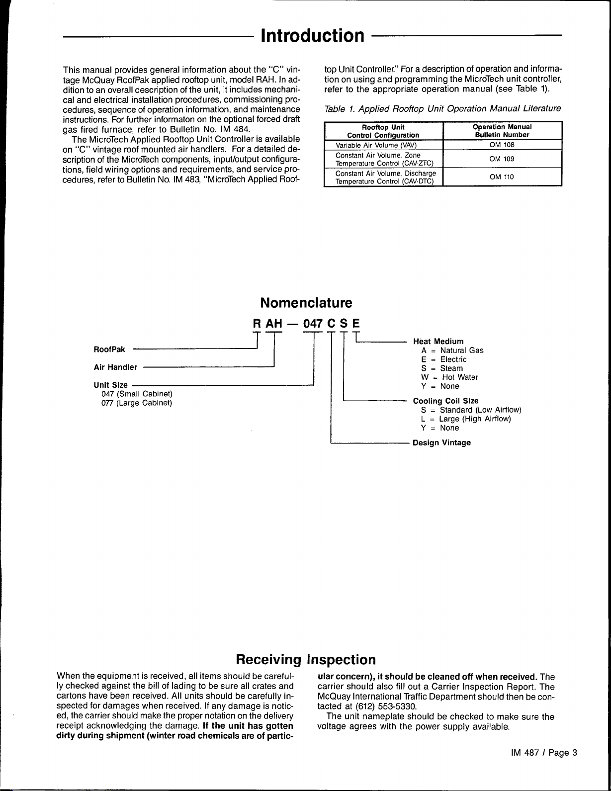
This manual provides general information about the “C” vintage McQuay RoofPak applied rooftop unit, model RAH. In ad-
I
dition to an overall description of the unit, it includes mechanical and electrical installation procedures, commissioning procedures, sequence of operation information, and maintenance
instructions. For further information on the optional forced draft
gas fired furnace, refer to Bulletin No. IM 484.
The MicroTech Applied Rooftop Unit Controller is available
on “C” vintage roof mounted air handlers. For a detailed description of the MicroTech components, input/output configurations, field wiring options and requirements, and service procedures, refer to Bulletin No. IM 483, “MicroTech Applied Roof-
R AH
RoofPak
~~~~~e= [-
047 (Small Cabinet)
077 (Large Cabinet)
top Unit Controller.” For a description of operation and information on using and programming the MicroTech unit controller,
refer to the appropriate operation manual (see Table 1).
Table 1. Applied Rooftop Unit Operation Manual Literature
Variable Air
Constant Air Volume, Zone
Temperature Control (CAV-ZTC)
Constant Air Volume, Discharge
Temperature Control (CAV-DTC)
Nomenclature
–047CSE
1
~ Designvintage
Rooftop Unit
Control Configuration
Volume (VAV)
Operation Manual
Bulletin Number
OM 108
OM 109
OM 110
Heat Medium
A = Natural Gas
E = Electric
S .
Steam
W = Hot Water
Y = None
Cooling Coil Size
S = Standard (Low Airflow)
L = Large (High Airflow)
Y = None
Receiving
When the equipment is received, all items should be carefully checked against the bill of lading to be sure all crates and
cartons have been received. All units should be carefully inspected for damages when received. If any damage is noticed, the carrier should make the proper notation on the delivery
receipt acknowledging the damage.
dirty during shipment (winter road chemicals are of partic-
If the unit has gotten
Inspection
ular concern), it should be cleaned off when received. The
carrier should also fill out a Carrier Inspection Report. The
McQuay International Traffic Department should then be con-
tacted at (612) 553-5330.
The unit nameplate should be checked to make sure the
voltage agrees with the power supply available.
IM 487 I Page 3
Page 4
Typical Component Locations
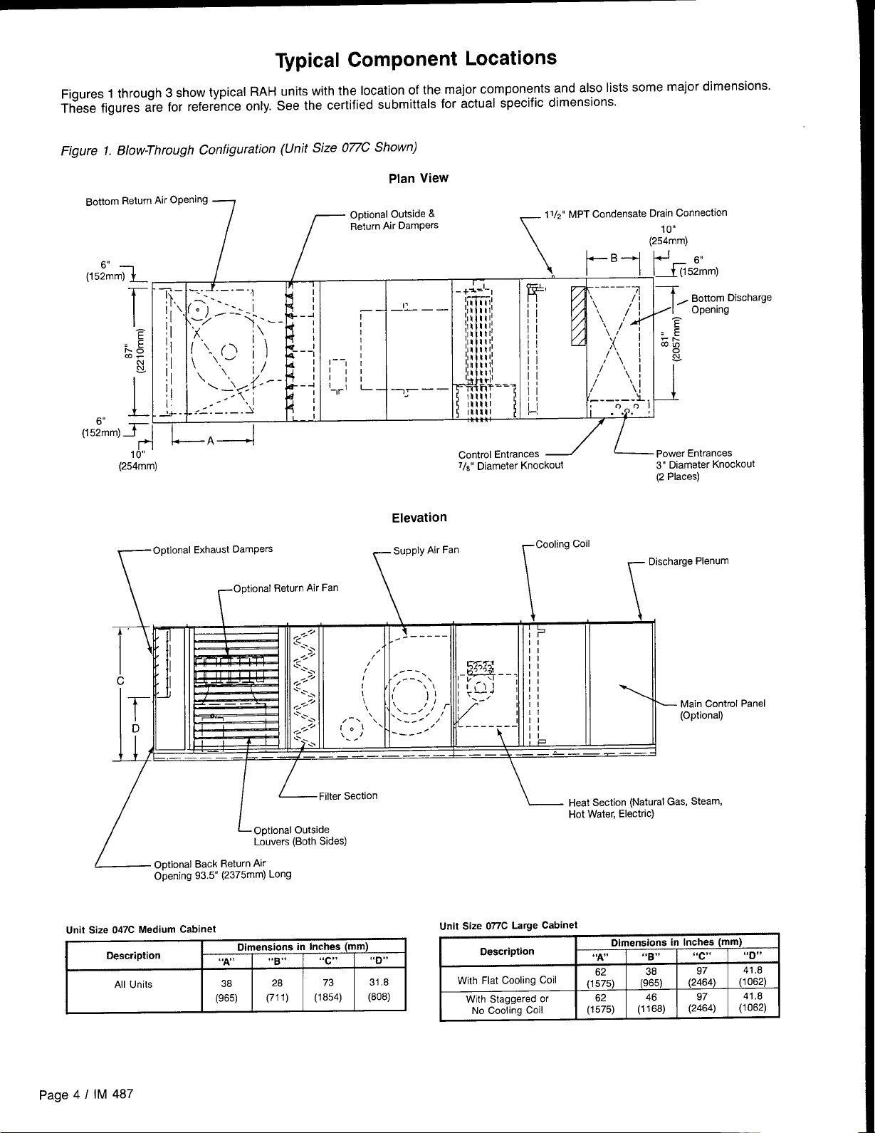
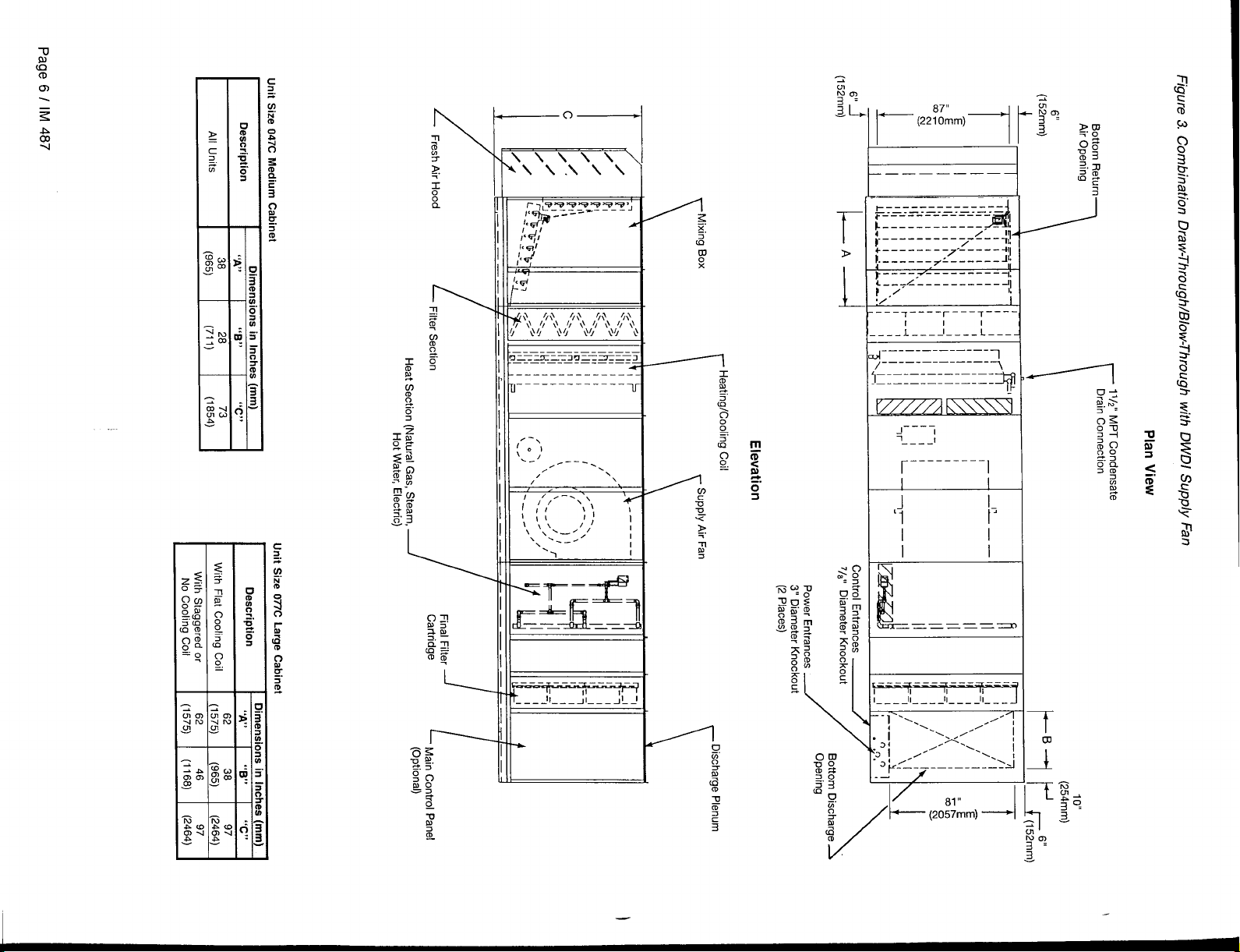
Figures 1 through 3 show typical RAH units with the location of the major components and also lists some major dimensions.
These figures are for reference only. See the certified submittals for actual specific dimensions.
Figure 1. Blow-Through Configuration (Unit Size 077C Shown)
Plan View
Bottom Return ~r Openin9 -
,,
(15;mm~
L
,!
(15;mm) ~
(254mm)
10“
r
I--A--I
optional Outside &
Return Air Dampers
f
11
—— —.
r
I
I
,-_l ~
l,,
l,,
I
-r’
-_——
L
Control Entrances _
7/*1’ Diameter Knockout
11/# MPTcondensateDrain Connection
‘I
/’
/’
/
j
(2J’mm)
L powerEntrances
3“ Diameter Knockout
(2 Places)
,,
, Bottom Discharge
Opening
Optional Exhaust Dampers
r
\ ‘r
,’
+ llL-==L=-1~
/
~ Optional Back Return Air
Unit Size 047C Medium Cabinet
II
/
Opening 93.5” (2375mm) Long
Optional Return Air Fan
,,./
g.
-.,
,,+
[<
.’.,
~,.,
-.
<.. .,
.,:/
G
/
L~i,tese.tiofl
L
Optional Outside
Louvers (Both Sides)
Elevation
supply Air Fan
T ‘i-
\
Cooling Coil
r
+
~.—----
.
/
i’
Unit Size 077C Large Cabinet
Description
With Flat Cooling Coil
Wth Staggered or
No Cooling Coil
II
,,
\
Heat Section (Natural Gas, Steam,
Hot Water, Electric)
“A”
(1$5)
(1:5)
Discharge Plenum
Main Control Panel
(Optional)
Dimensions in Inches (mm)
“B”
(::5)
(1%8)
“c.
(2%4)
(2:4)
“D,*
41.8
(1062)
41.6
(1062)
page 4 I IM 487
Page 5
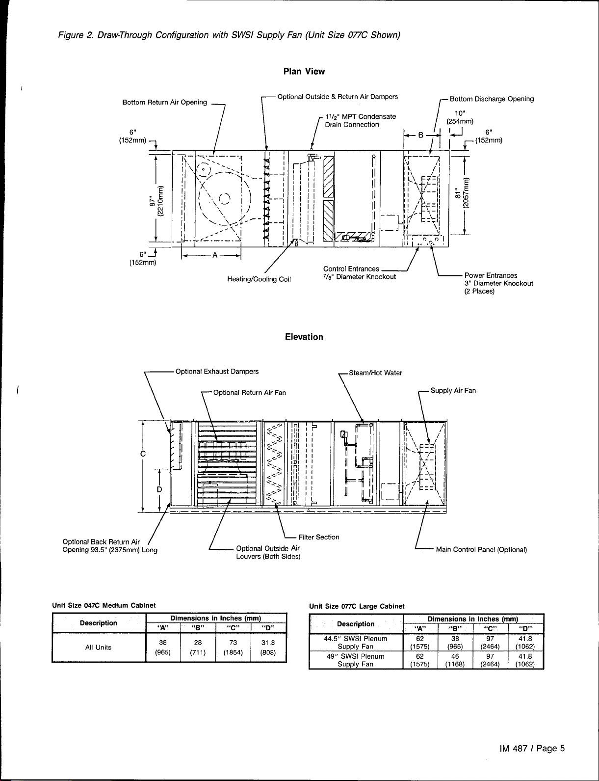
Figure 2. Draw-Through Configuration with SWSI Supply Fan (Unit Size 077C Shown)
Plan View
Optional
Bottom Return Air Opening
1
r
Outside & Return Air Dampers
1Ilz” MPT Condensate
Drain Connection
r
Bottom 13scharge Opening
r
10’”
(254mm)
I
~Bfl ‘~(15.%m)
~——~.
11,
II . .
~.o.
01
\
l-]
c
1[
7“’
Optional Back Return Air
Opening 93.5” (2375 mm) Long
Heating/Cooling Coil
Optional Exhaust Dampers
Optional Return Air Fan
\
T
D
I
/
r
.——_———.——_.—————————
L
/
Elevation
\ I
L ~lter section
Optional Outside Air
Louvers (Both Sides)
Control Entrances _
718”Diameter Knockout
-+-t
Water
\
Supply Air Fan
Power Entrances
3“ Diameter Knockout
(2 Places)
r
.
L-
Main Control Panel (Optional)
Lrnit siZe 047C Medium Cabinet
~
Unit Size 077’CLarge Cabinet
~
IM 487 I Page 5
Page 6
——— ————— .
~_____-–––-––__
—.—.—.—.—.—.—.—
*-------------
L------------, - !
;-----
----– –,- Z--114
+--- ___7______4,,4,,
>
L______7L__-_--Jlo
F--–-.+-––-----1!
Jai!
w
:/’
L
-––7----r–_–T____
---1--__l–---:____
~.–-– -—————-—-
,-—-—-—
~_-–- —_—-—-———-
-—-—
J
1
-—--
~---- —----
I
7’
—————
—————.
IL
—---—- -—-
II
l_–__ll____ll____ll____
I
!
1, 11
q
+
I
I
I
=x
-—--
I
T
al
v
q-
5
I/
I
—
Page 7
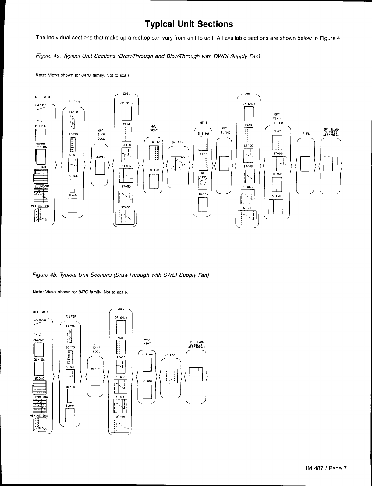
Typical Unit Sections
—
The individual sections that make up a rooftop can vary from unit to unit. All available sections are shown below in Figure 4.
Figure 4a. Typical Unit Sections (Draw-Through and Blow-Through with DWDI Supply Fan)
Note: Views shown for 047C family. Not to scale
RET.&lR
0~/HOOD‘
a
PLENUM
u
30L DA
II
ECONO
s
ECONO/R&
R
MlXlNCBOX
,:
.:
: !0,,
n
OPT
EV&P
COOL
8LANK
n
[:
?- . ...,
!. /---
❑
[1
S6 FfiN
,----
,-,
--
II
---
PLEN
J
Figure 4b. ~pical Unit Sections (Draw-Through with SWSI Supply Fan)
Note: Views shown for 047C family. Not to scale.
FILTER
-.
TA/30
:>
:.
,:
i
65/95
,!
“$;
,,
.,
,,
[
STAGG
pl
I
OL~NK
[
OLONK
u
OPT
EVR?
COOL
.
BLANK
u
1
.
/
h-w
HEbT
IM 487 I Page 7
Page 8
Control Locations
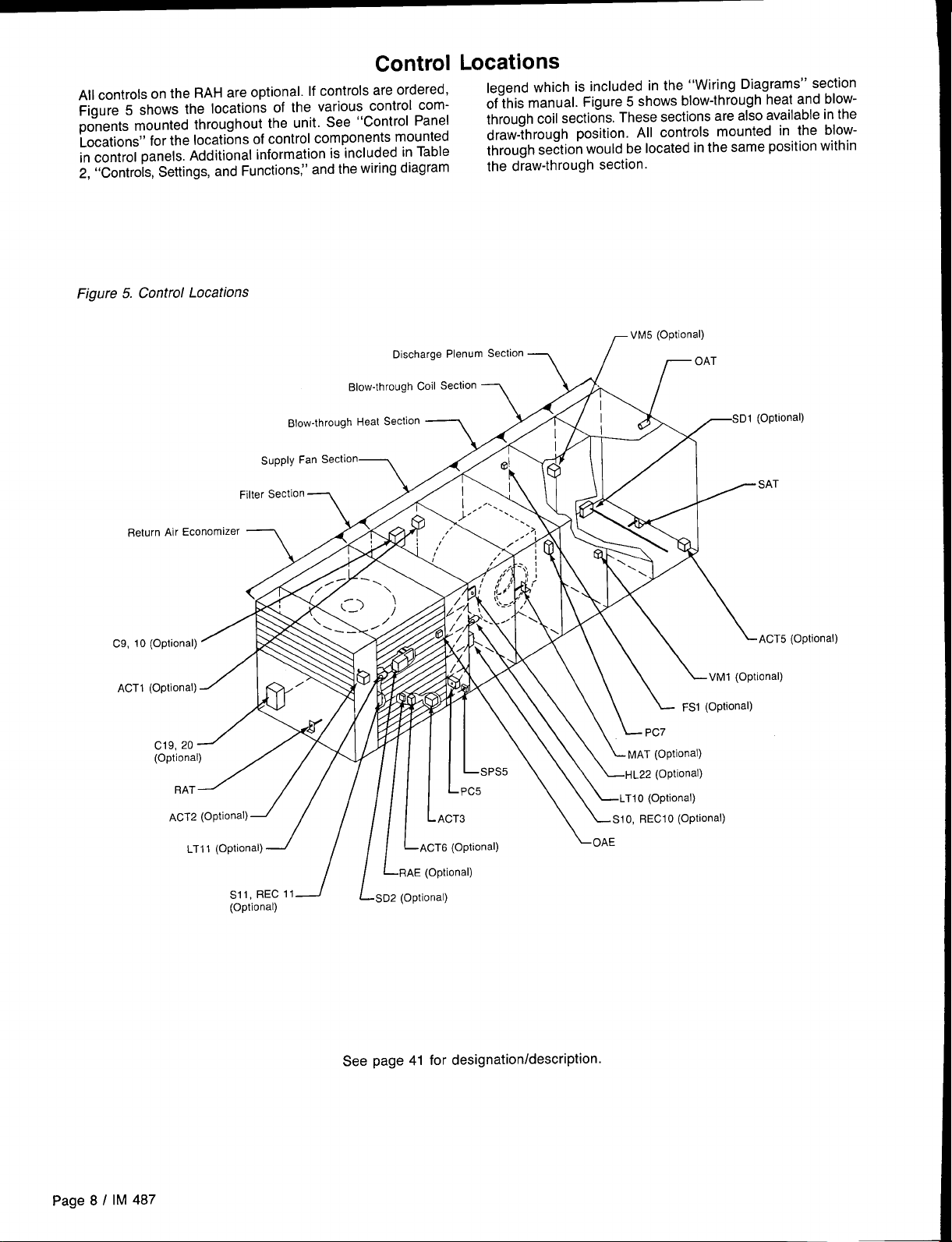
All controls on the RAH are optional. If controls are ordered,
Figure 5 shows the locations of the various control components mounted throughout the unit. See “Control Panel
Locations” for the locations of control components mounted
in control panels. Additional information is included in Table
2, “Controls, Settings, and Functions,” and the wiring diagram
Figure 5. Control Locations
Oischarge Plenum Section
Blow-through coil SeCtiOn
legend which is included in the ‘rWiring Diagrams” section
of this manual. Figure 5 shows blow-through heat and blowthrough coil sections. These sections are also available in the
draw-through position. All controls mounted in the blowthrough section would be located in the same position within
the draw-through section.
Return Air Economizer _
C9, 10 (Optional)
ACT1 (Optional)
C19, 20
(Optiona
RAT
ACT2
LTI 1 (OptiOnal)
SUpply Fan Section
Filter SeCtiOn
-/
SII, REC1l
(Optional)
Blow-through Heat
7
Fka
1 [[
Section
SD2 (Optional)
L
ACT6 (Optional)
RAE (Optional)
\\l v-’\ \ \
\oA,
SD1 (Optional)
~ SAT
\~cT~
VM1 (Optional)
Optional)
(Optional)
Page 8 / IM 487
See page 41 for designationldescription.
Page 9
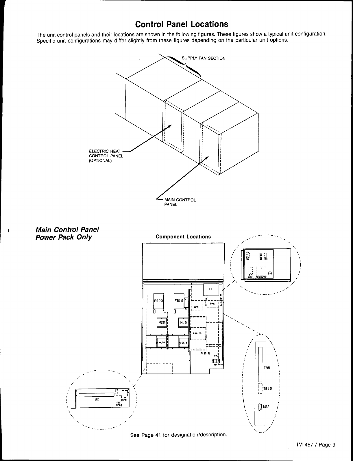
Control Panel Locations
The unit control panels and their locations are shown in the following figures. These figures show a typical unit configuration.
Specific unit configurations may differ slightly from these figures depending on the particular unit options.
Main Control Panel
Power Pack Only
..-” ”— ”---- . ..
/.”.
~~
(bii‘“
\ /’
‘>\
,.
,.
.. .
.. ... ... ..- ... .
PANEL
Component Locations
.
..
1’
\
~,.,
\,
‘ “.
;
/’
,,
,/
./.
See Page 41 for designationldescription.
~..-.. —-----
”
.,.
,/’
./
/’ --
fj
i
%
,., . . . . .
\
‘.lm
,/’” ..
,! ::;
,,
+-.!:-:--: @)
\
RE61WRIWM
~\
x.
.,. ,
. ..
I
i
I
I
1,
“..b /
\
. ... ... ..-
\
1 ~
\
..
\
----
~;,
rB5 I
rBl 0 !
,./
,./
. .
.,
..
..-
\
\
\
I
I
I
;
;
...
‘\
,.
\
\
I
i
/’
/’
,.
/
IM 487 I Page
9
Page 10
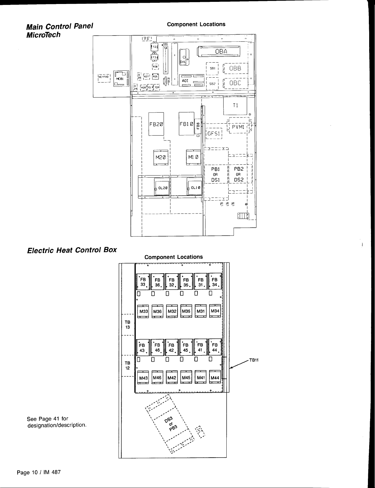
Main Control Panel
---
IKE”P.D/
.——.
‘L
0===[
❑ —
Component Locations
I r
T1
. .
M2@
I
u
c
u
Control
Box
—
Component Locations
.
..-
Elmml!q
TB
13
---
..TB
12
---
I
.
II
I
I
I
/“”
See Page41 for
designation/description.
Page 10 / IM 487
\- “,
‘.””’”OS: ‘N,
\
\
\
pf$’ ,,.1, ‘-’
\
\
\
,.
\
,.
\
.,. -
,.-,[:, .
\
‘,,(; , .
.
\
\
. ~,
,.’ ;’. ,
‘,::’-,
\z.,
Page 11
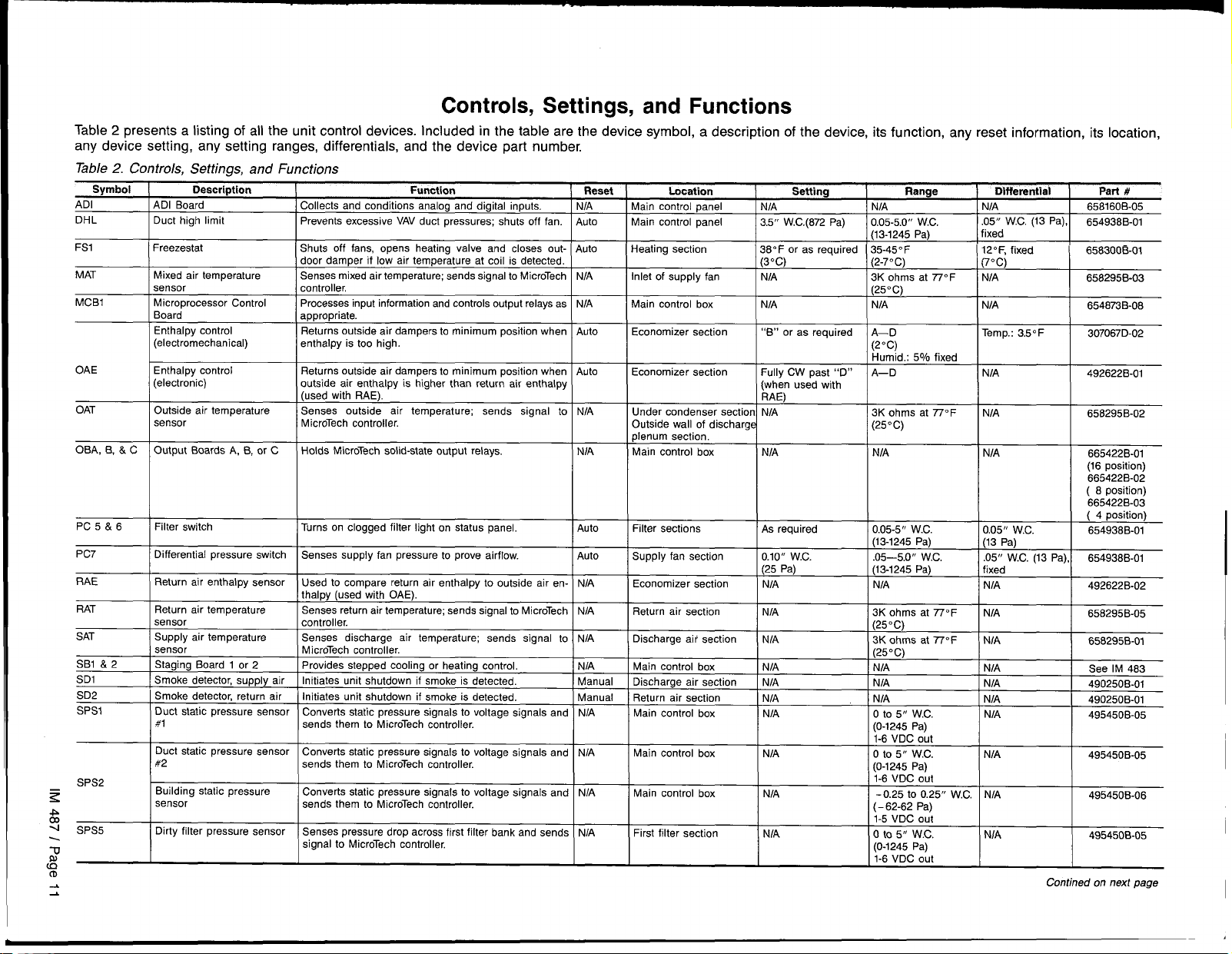
Controls, Settings, and Functions
Table 2 presents a listing of all the unit control devices. Included in the table are the device symbol, a description of the device, its function, any reset information, its location,
any device setting, any setting ranges, differentials, and the device part number.
Table 2. Controls, Settings, and Functions
Symbol
ADI
DHL
FS1
MAT
MCB1
OAE
OAT
OBA, B, & C
PC 5&6
PC?
Description
ADI Board
Duct high limit
Freezestat
Mixed air temperature
sensor
Microprocessor Control
Board
Enthalpy control
(electromechanical)
Enthalpy control
(electronic)
Outside air temperature
sensor
Output Boards A, B, or C
Filter switch
Differential pressure switch
Function
Collects and conditions
Prevents excessive VAV duct pressures; shuts
Shuts off fans, opens heating valve and closes outdoor damper if low air temperature at coil is detected.
Senses mixed air temperature; sends signal to MicroTech
controller,
Processes input information and controls output relays as
appropriate.
Returns outside air dampers to minimum position when Auto
enthalpy is too high.
Returns outside air dampers to minimum position when Auto
outside air enthalpy is higher than return air enthalpy
(used with RAE).
Senses outside air temperature; sends signal to
MicroTech controller.
Holds MicroTech solid-state output relays.
Turns on clogged filter light on status panel.
Senses supply fan pressure to prove airflow.
analog and digital inputs. NIA
off fan. Auto
Auto
NIA
NIA
NIA
NIA
Auto
Auto
Reset
I
Location
Main control
Main control panel
Heating section
I
Inlet of supply fan
Main control box
Economizer section
Economizer section
Under condenser section N/A
Outside wall of discharge (25”C)
plenum section.
Main control box
panel NIA
Setting
NIA
3.5” W.C.(872 Pa)
38° F or as required
(3”C)
NIA 3K ohms at 77° F
I N/A
“B” or as required A—O
Fully CW past “D” A—D
(when used with
RAE)
NIA NIA
0.05-5.0” W.c,
(13-1245 Pa)
35-450 F
(2-7oC)
(25”C)
I NIA
(20c)
Humid.: 50/o fixed
3K ohms at 77° F
Range
Dlfferentisl
UIA
05” W.C. (13 Pa),
ixed
+
+
+
NIA
0.05” WC.
Part #
858160B-05
654938B-01
665422B-01
(16 position)
665422B-02
( 8 position)
665422B-03
( 4 position)
654936B-01
RAE
RAT
SAT
SB1 & 2
SD1
SD2
SPS1
SPS2
z
*
co
+
SPS5
\
-o
&
CD
Return air enthalpy sensor
Return air temperature
sensor
Supply air temperature
sensor
Staging Board 1 or 2
Smoke detector, supply air
Smoke detector, return air
Duct static pressure sensor Converts static pressure signals to voltage signals and
#1
Duct static pressure sensor COMKMS static pressure signals to voltage signals and
#2
Building static pressure
sensor
Dirty filter pressure sensor
Used to compare return air enthalpy to outside air en-
thalpy (used with OAE).
Senses return air temperature; sends signal to MicroTech NIA
controller.
Senses discharge air temperature; sends signal to
MicroTech controller.
Provides stepped cooling or heating control.
Initiates unit shutdown if smoke is detected.
Initiates unit shutdown if smoke is detected.
sends them to MicroTech controller.
sends them to MicroTech controller.
Converts static pressure signals to voltage signals and NIA
sends them to MicroTech controller.
Senses pressure drop across first filter bank and sends NIA
signal to MicroTech controller,
NIA
NIA
NIA
Manual
Manual
NIA
NIA
Return air section
Discharge air section
Main control box
Discharge air section
Return air section
Main control box
Main control box
I I
I NIA I 3K ohms at 770F
I NIA
NIA NIA
NIA
I NIA I NIA
] N/A
NIA o to 5 ‘f WC.
I (25”C)
13K ohms at 7T” F
(25oC)
NIA
Io to 5“ WC.
(0-1245 Pa)
1-8 VDC out
N/A
NIA
N[A
NIA
I 6582!35B-05
I
658295B-01
I
495450B-05
I
1
495450B-05
I
Contined on next page
Page 12
CD
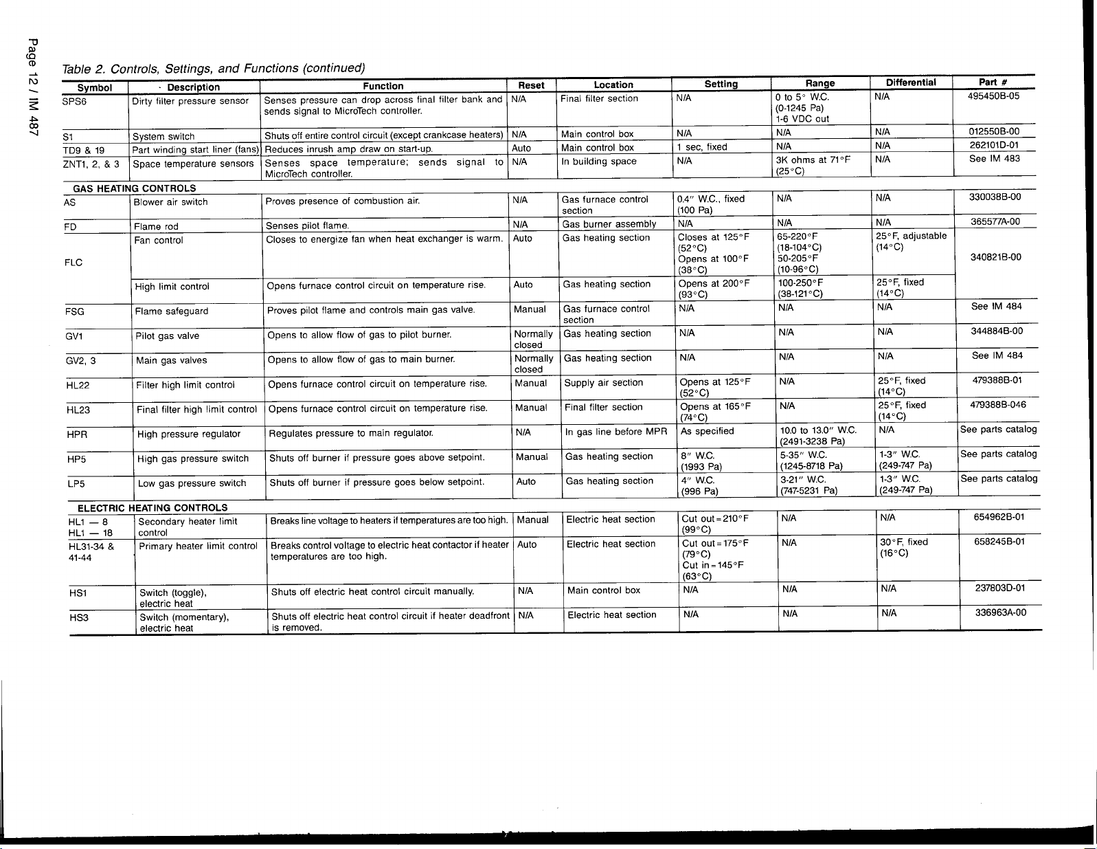
Table 2. Controls, Settings, and Functions (continued)
N
z
.P
co
4
Symbol
SPS6
S1 System switch
TD9 & 19 Part winding start liner (fans) Reduces inrush amp draw on start-up.
ZNT1, 2, & 3 Space temperature sensors Senses space temperature; sends signal to
GAS HEATI
NG CONTROLS
AS
FD
FLC
FSG Flame safeguard Proves pilot flame and controls main gas valve.
GV1 Pilot gas valve Opens to allow flow of gas to pilot burner.
GV2, 3
HL22 Filter high limit control Opens furnace control circuit on temperature rise.
HL23 Final filter high limit control Opens furnace control circuit on temperature rise.
HPR High pressure regulator Regulates pressure to main regulator.
HP5 High gas pressure switch Shuts off burner if pressure goes above setpoint.
LP5 Low gas pressure switch
Description Function
Dirty filter pressure sensor Senses pressure can drop across final filter bank and
air switch
Blower
Flame rod
Fan control Closes to energize fan when heat exchanger is warm. Auto
High limit control
Main gas valves Opens to allow flow of gas to main burner.
sends signal to MicroTech controller.
Shuts off entire control circuit (except crankcase heaters)
MicroTech controller.
Proves presence of combustion air.
Senses pilot flame.
Opens furnace control circuit on temperature rise.
Shuts off burner if pressure goes below setpoint.
ELECTRIC HEATING CONTROLS
HL1 — 8
HL1 — 18
HL31-34 & Primary heater limit control
41-44 temperatures are too high.
HS1
HS3 Switch (momentary), Shuts off electric heat control circuit if heater dead front
Secondary heater limit
control
Switch (toggle),
electric heat
electric heat is removed.
Breaks line voltage to heaters if temperatures are too high.
Breaks control voltage to electric heat contactor if heater
Shuts off electric heat control circuit manually.
Reset Location
NIA
NIA
Auto
NIA
N/A
N/A Gas burner assembly
Auto Gas heating section
Manual
Normally Gas heating section
closed
Normally Gas heating section
closed
Manual Supply air section Opens at 125° F
Manual
N/A
Manual
Auto Gas heating section
Manual
Auto
N/A
N/A
Final filter section NIA
Main control box
Main control box 1 see, fixed
In building space N/A
Gas furnace control 0.4” WC., fixed
section
Gas heating section Closes at 125° F
Gas furnace control
section
Final filter section
In gas line before MPR
Gas heating section 6“ W.C,
Electric heat section Cut out=210° F
Electric heat section Cut out=175° F
Main control box NIA
Electric heat section
Setting
N/A
(100 Pa)
N/A
(52”C)
Opens at 100” F
(36oC)
Opens at 200” F
(93”C)
NIA
NIA
N/A
(52°C)
Opens at 1650F
(74”C)
As specified
(1993 Pa)
4“ W.c.
(996 Pa)
(99”C)
(79”C)
Cut in=145° F
(63oC)
NIA
Range
o to 5“ W.c.
(0-1245 Pa)
1-6 VDC out
NIA
N/A
3K ohms at 71° F
(25”C)
N/A
NIA NIA
65-220” F
(18-104°C)
50-205° F
(10-96oC)
100-2500 F
(38-121”C)
NIA N/A
N/A
NIA
N/A
N/A
10.0to 13.0” W.c.
(2491-3238 Pa)
5-35 ‘c W.c.
(1245-8718 Pa) (249-747 Pa)
3-21“ W.C.
(747-5231 Pa)
N/A
NIA
NIA
NIA
Differential Part #
N/A 495450B-05
NIA 012550B-00
N/A
NIA
NIA
25° F, adjustable
(14”C)
250 F, fixed
(14”C)
N/A 344864B-00
N/A See IM 484
250 F, fixed 479388B-01
(14”C)
25” F, fixed 479388 B-046
(14”C)
NIA See parts catalog
1-3” WC, See parts catalog
1-3“ W.c. See parts catalog
(249-747 Pa)
NIA
300 F, fixed 658245B-01
(16”C)
NIA
NIA 336963A-00
262101D-O1
See IM 483
330036B-00
365577A-00
340821B-00
See IM 484
654962B-01
237803D-01
Page 13
Mechanical Installation
The installation of this equipment shall be in accordance with
the regulations of authorities having jurisdiction and all applicable codes. It is the responsibility of the installer to determine and follow the applicable codes.
Unit Clearances
Service Clearance
Sharp edges are inherent to sheet metal parts, screws,
clips, and similar items. Can cause personal injury.
This equipment is to be installed and operated only by an experienced installation company and fully trained personnel.
Exercise caution when servicing equipment.
I
I
I
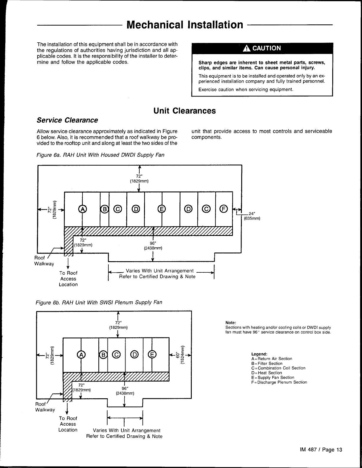
Allow service clearance approximatelv as indicated in Figure
6 below. Also, it is recommended that a roof walkway bepro-
vialed to the rooftop unit and along at least the two sides of the
Figure 6a. RAH Unit With Housed DWDI Supply Fan
r
,!
(18~mm)
Location
unit that provide access to most controls and serviceable
components.
—24”
[635mm)
Figure 6b. RAH Unit With SWSI Plenum Supply Fan
I r
1 1 I I I I I
F
:E
—No
hLu-
m
g
?
/ Y//////////M//////////&
(18~m)
-WI
r V..
m—_’ / I 1~
rluwl
Walkway
TO Roof
Access
Location
v//4
.
i
8 G 0
Varies With Unit Arrangement
Refer to Certified Drawing & Note
T
,,
(24$mm)
v
1
I I
P
I
‘1
Note:
Sections
with heating and/or cooling coils or DWDI supply
fan must have 96” service clearance on control box side.
Legend:
A= Return Air Section
B=Filter Section
C=Combination Coil Section
D=Heat Section
E=Supply Fan Section
F= Discharge Plenum Section
IM 487 I Page 13
Page 14
Ventilation Clearance
Following are minimum ventilation clearance recommendations. The system designer must consider each application
and assure adequate ventilation. If this is not done, the unit
will not perform properly.
Unit(s) surrounded by a screen or fence:
The bottom of the screen or fence should be at least one
1.
foot above the roof surface.
2. The distance between the unit and the screen or fence
should be as described in “Service Clearance” above.
3. The distance between any two units within the screen or
fence should be at least 120 inches (3048mm).
Unit(s) surrounded by solid walls:
1, If there are walls on one or two adjacent sides of the unit,
the walls may be any height, If there are walls on more
than two adjacent sides of the unit, the walls should not
be higher than the unit.
2. The distance between the unit and the wall should be at
least 96 inches (2438 mm) on all sides of the unit.
3. The distance between any two units within the walls should
be at least 120 inches (3048mm).
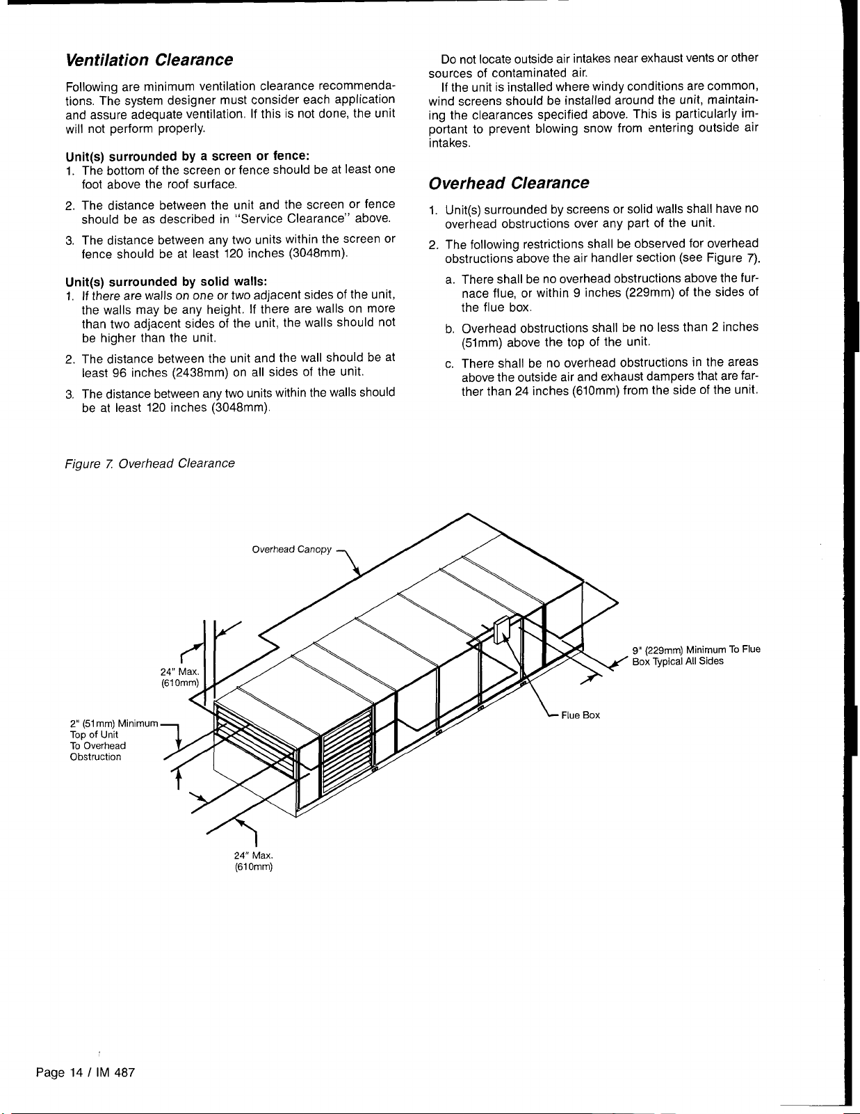
Figure z Overhead Clearance
Do not locate outside air intakes near exhaust vents or other
sources of contaminated air.
If the unit is installed where windy conditions are common,
wind screens should be installed around the unit, maintain-
ing the clearances specified above. This is particularly important to prevent blowing snow from entering outside air
intakes.
Overhead Clearance
1. Unit(s) surrounded by screens or solid walls shall have no
overhead obstructions over any part of the unit.
2. The following restrictions shall be observed for overhead
obstructions above the air handler section (see Figure 7).
a. There shall be no overhead obstructions above the fur-
nace flue, or within 9 inches (229mm) of the sides of
the flue box.
b. Overhead obstructions shall be no less than 2 inches
(51mm) above the top of the unit.
c. There shall be no overhead obstructions in the areas
above the outside air and exhaust dampers that are farther than 24 inches (610mm) from the side of the unit.
2“ (51mm) Minimum
Top of Unit
To Overhead
Obstruction
24” Max.
(61Omm)
9“ (229mm) Minimum To Flue
Box Typical All Sides
Page 14 / IM 487
Page 15
Roof Curb Assembly and Installation
I
The roof curb and unit must be located on a portion of the
roof that can support the weight of the unit. The unit must
be supported to prevent bending or twisting of the machine.
If building construction could allow the transmission of
sound and vibration into the occupied space, it is recommended that the unit be located over a noncritical area. It is
flanges seals against the unit when it is set on the curb. It
is not recommended that these flanges support the total
weight of the ductwork. Refer to the “installing Ductwork” section for details on duct connections.
Assembly of a typical RAH roof curb is shown in Figures
8a and 8b. Refer to instruction drawing provided with roof curb.
the responsibility of the system designer to make adequate Parts A through H are common to all units having bottom
provisions for noise and vibration in the occupied space.
Integral supply and return air duct flanges are provided with
the RAH roof curb, allowing connection of ductwork to the curb
before the unit is set. The gasketed top surface of the duct
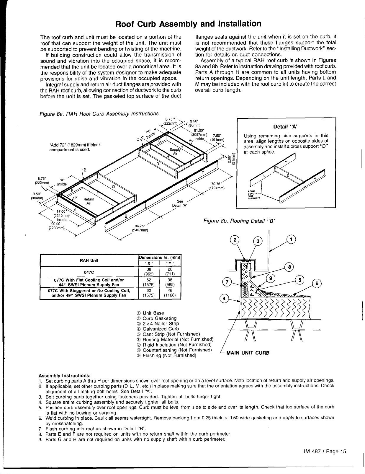
Figure 8a. RAH Roof Curb Assembly Instructions
,,.
(Z!i;;m>+ ~jo~m)
return openings. Depending on the unit length, Parts L and
M maybe included with the roof curb kit to create the correct
overall curb Iength.
.
Detail “A’
Using remaining side supports in this
area, align lengths on opposite sides of
assembly and install a cross support “D”
at each splice.
EOUAL
:W[GT “
SUPPORTS
A
RAH Unit
047C
077C With Flat Cooling Coil and/or
4411 SWSI Plenum Supply Fan
077C With Staggered or No Cooling Coil,
and/or 49fI SWSI Plenum Supply Fan
Assembly Instructions:
1.
Set c;rbing parts A thru H per dimensions shown over roof opening or on a level surface. Note location of return and SU!JDIVair oReninW
If applicable, set other curbing parts (D, L, M, etc.) in place making sure that the orientation agrees with the assembly instrfictions. Ch[ck
2.
alignment of all mating bolt holes. See Detail “A’.
Bolt curbing parts together using fasteners provided. Tighten all bolts finger tight.
3.
Square entire curbing assembly and securely tighten all bolts.
4.
Position curb assembly over roof openings. Curb must be level from side to side and over its length. Check that top surface of the curb
5.
is flat with no bowing or sagging.
Weld curbing in place. Caulk aH seams watertight. Remove backing from 0.25 thick
6.
by crosshatching.
Flash curbing into roof as shown in Detail “B”.
7.
Parts E and F are not required on units with no return shaft within the curb perimeter.
8.
Parts G and H are not required on units with no supply shaft within curb perimeter.
9.
3imensions in. (mm)
“x”
(::5)
(1:5)
(1%5) (1%8)
Unit Base
Curb Gasketing
2 x 4 Nailer Strip
Galvanized Curb
Cant Strip (Not Furnished)
Roofing Material (Not Furnished)
Rigid Insulation (Not Furnished)
C&nterflashing (Not Furnished) ~ ~A,N “NIT CURB
Flashing (Not Furnished)
“y,.
(;: )
(::5)
x 1.50 wide gasketing and apply to surfaces shown
IM 487 I Page 15
Page 16
Post and Rail Mounting
When mounting by Post and rail, the structural support should
run the full length of the unit to prevent any deflection of
be
the cabinet. The structural member should be located at the
base of the unit as shown in Figure 9 assuring the shaded
area is well supported by the structural member.
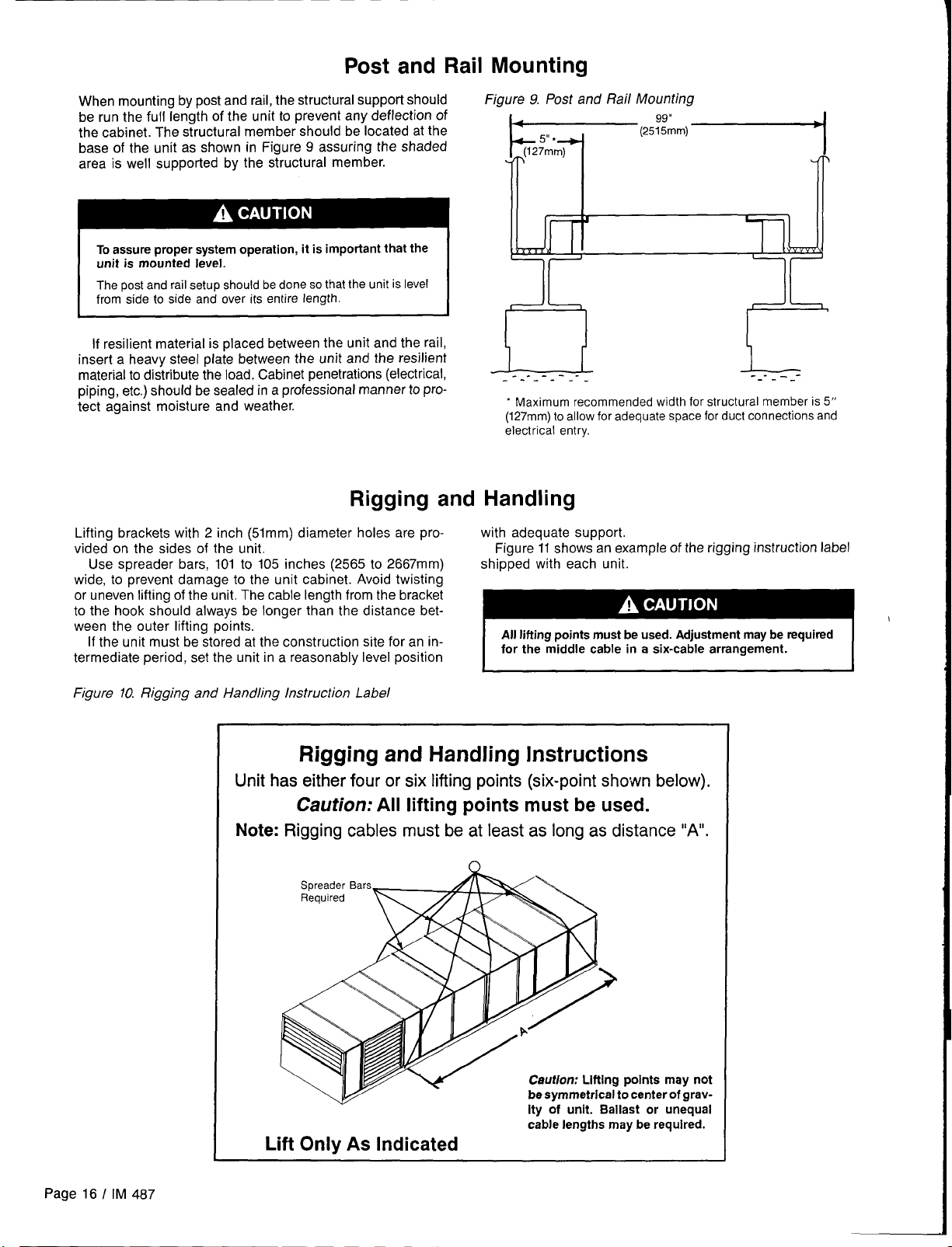
Figure 9. Post and Rail Mounting
4
,,
(12~m’m)
‘2’;;”)-
l’rl T
To assure proper system operation, it is important that the
unit is mounted level.
The post and rail setup should be done so that the unit is level
from side to side and over its entire length.
If resilient material is placed between the unit and the rail,
insert a heavy steel plate between the unit and the resilient
material to distribute the load. Cabinet penetrations (electrical,
piping, etc.) should be sealed in a professional manner to pro- tect against moisture and weather.
Rigging and Handling
Lifting brackets with 2 inch (51mm) diameter holes are pro-
vialed on the sides of the unit. Figure 11 shows an example of the rigging instruction label
Use spreader bars, 101 to 105 inches (2565 to 2667mm)
wide, to ‘prevent damage to the unit cabinet. Avoid twisting
or uneven lifting of the unit. The cable length from the bracket
to the hook should always be longer than the distance between the outer lifting points.
If the unit must be stored at the construction site for an in-
termediate period, set the unit in a reasonably level position
!l_l!!l_
------ ----
“ Maximum recommended width for structural member
(127mm) to allow for adequate space for duct connections and
electrical entry
with adequate support.
shipped with each unit.
All lifting points must be used. Adjustment maybe required
for the middle cable in a six-cable arrangement.
-------
is 5“
Figure 10. Rigging and Handling Instruction Label
Rigging and Handling Instructions
Unit has either four or six lifting points (six-point shown below),
Caution: All lifting points must be used.
Note: Rigging cables must beat least as long as distance “A”.
Sprea
Requi
/v
Lift Only As Indicated
Caution: Lifting points may not
be symmetrical to center of gravity of unit. Ballast or unequal
cable lengths may be required.
Page 16 / IM 487
Page 17
I
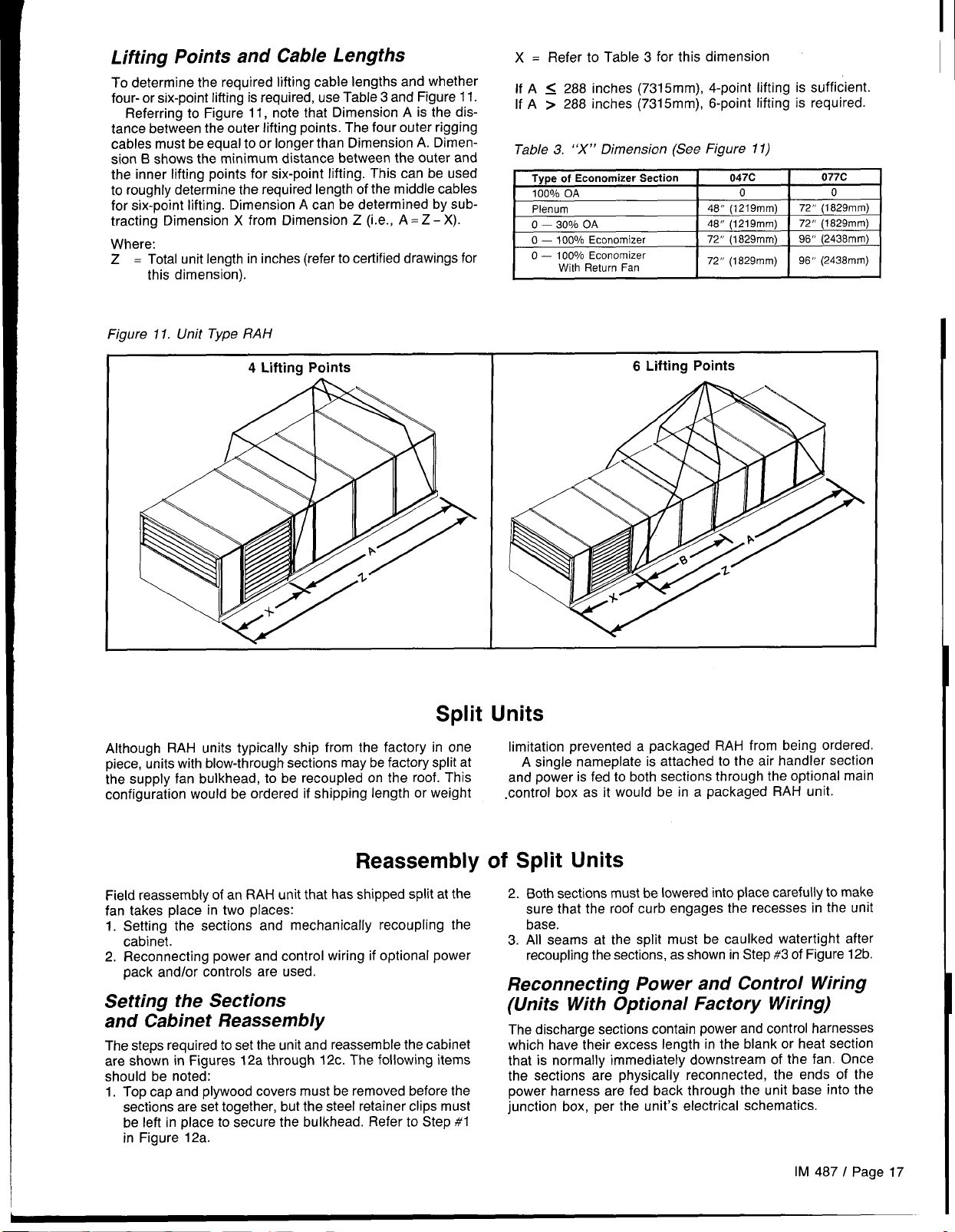
Lifting Points and Cable Lengths
To determine the required lifting cable lengths and whether
four- or six-point lifting is required, use Table 3 and Figure 11.
Referring to Figure 11, note that Dimension A is the distance between the outer lifting points. The four outer rigging
cables must be equal to or longer than Dimension A. Dimen-
sion B shows the minimum distance between the outer and
the inner lifting points for six-point lifting. This can be used
to roughly determine the required length of the middle cables
for six-point lifting. Dimension A can be determined by sub-
tracting Dimension X from Dimension Z (i.e., A = Z - X).
Where:
Z = Total unit length in inches (refer to certified drawings for
this dimension).
Figure 11. Unit Type RAH
4 Lifting Points
X = Refer to Table 3 for this dimension
If A < 288 inches (7315mm), 4-point lifting is sufficient.
If A > 288 inches (7315mm), 6-point lifting is required.
Table 3. “X” Dimension (See Figure 11)
Type of Economizer Section
100%OA
Plenum
O —
2.00/o OA
O — 100°/0 Economizer
O — 100°10 Economizer
With Return Fan
I
6 Lifting Points
047C
o
48” (1219 mm)
48” (1219 mm)
72” (1829mm)
72” (1829 mm)
72” (1829mm)
72” (1829 mm)
96” (2438 mm)
96” (2438 mm)
077C
0
Split Units
Althouqh RAH units typically ship from the factory in one
piece, units with blow-through sections maybe factory split at
the supply fan bulkhead, to be recoupled on the roof. This
configuration would be ordered if shipping length or weight
Reassembly
Field reassembly of an RAH unit that has shipped split at the
fan takes place in two places:
1. Setting the sections and mechanically recoupling the
cabinet.
2. Reconnecting power and control wiring if optional power
pack and/or controls are used.
Setting the Sections
and Cabinet Reassembly
The steps required to set the unit and reassemble the cabinet
are shown in Figures 12a through 12c. The following items
should be noted:
1. Top cap and plywood covers must be removed before the
sections are set together, but the steel retainer clips must
be left in place to secure the bulkhead. Refer to Step #1
in Figure 12a.
limitation prevented a packaged RAH from being ordered.
A single nameplate is attached to the air handler section
and power is fed to both sections through the optional main
control box as it would be in a packaged RAH unit.
of Split Units
2. Both sections must be lowered into place carefully to make
sure that the roof curb engages the recesses in the unit
base.
3. All seams at the split must be caulked watertight after
recoupling the sections, as shown in Step #3 of Figure 12b.
Reconnecting Power and Control Wiring
(Units With Optional Factory Wiring)
The discharge sections contain power and control harnesses
which have their excess length in the blank or heat section
that is normally immediately downstream of the fan. Once
the sections are physically reconnected, the ends of the
power harness are fed back through the unit base into the
junction box, per the unit’s electrical schematics.
IM 487 I Page 17
Page 18
Care must be exercised to connect the proper power block
and maintain proper phasing.
I
When reconnection of the power wires is complete, the inner raceway cover in the blank or heat section must be
reinstalled. Step #4 of Figure 12c shows a typical installation
of the raceway cover.
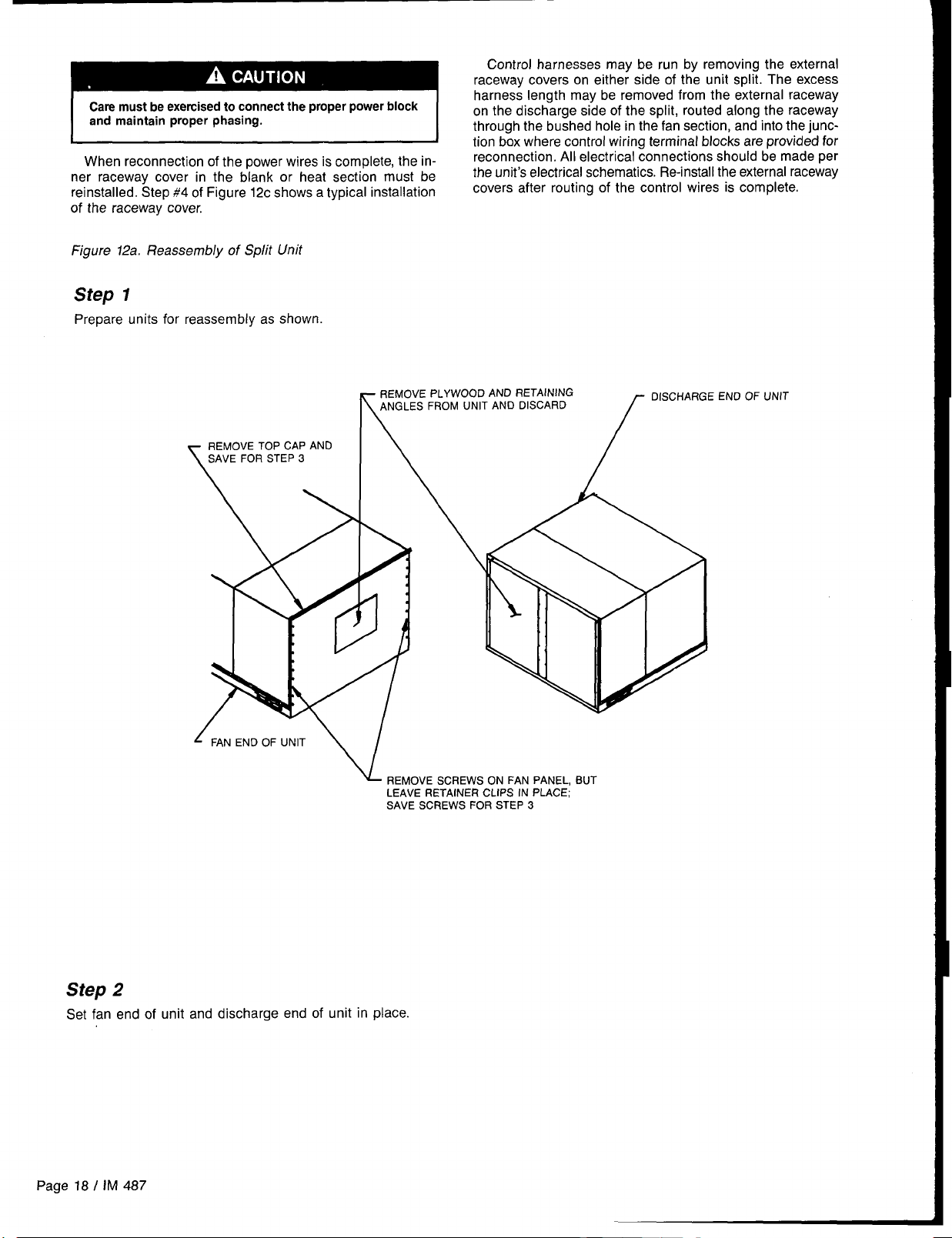
Figure 12a. Reassembly of Split Unit
Step 1
Prepare units for reassembly as shown.
Control harnesses may be run by removing the external
raceway covers on either side of the unit split. The excess
harness length may be removed from the external raceway
on the discharge side of the split, routed along the raceway
I
through the bushed hole in the fan section, and into the junc-
tion box where control wiring terminal blocks are provided for
reconnection. All electrical connections should be made per
the unit’s electrical schematics. Re-install the external raceway
covers after routing of the control wires is complete.
REMOVE PLYWOOD AND RETAINING
ANGLES FROM UNIT AND DISCARD
k
L
REMOVE SCREWS ON FAN PANEL, BUT
LEAVE RETAINER CLIPS IN PLACE;
SAVE SCREWS FOR STEP 3
OISCHARGE END OF UNIT
f
Step 2
Set fan end of unit and discharge end of unit in place.
Page 18 I IM 487
Page 19
r
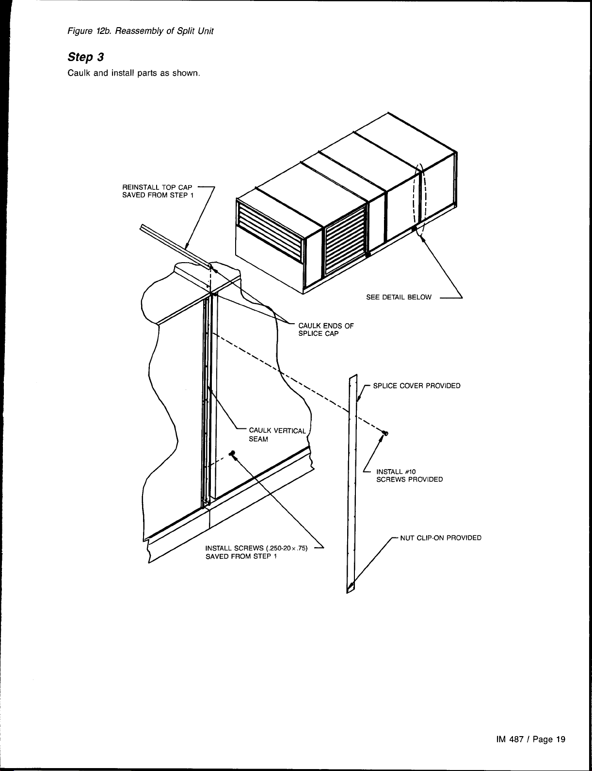
Figure 12b. Reassembly of Split Unit
Step 3
Caulk and install parts as shown.
\
CAULK VERTICAL
SEAM
SPLICE COVER PROVIDED
f
‘\
)
“%
[
INSTAL
SCREWS PROVIDED
NUT CLIP-ON PROVIDED
#lo
/
IM 487 / Page 19
Page 20
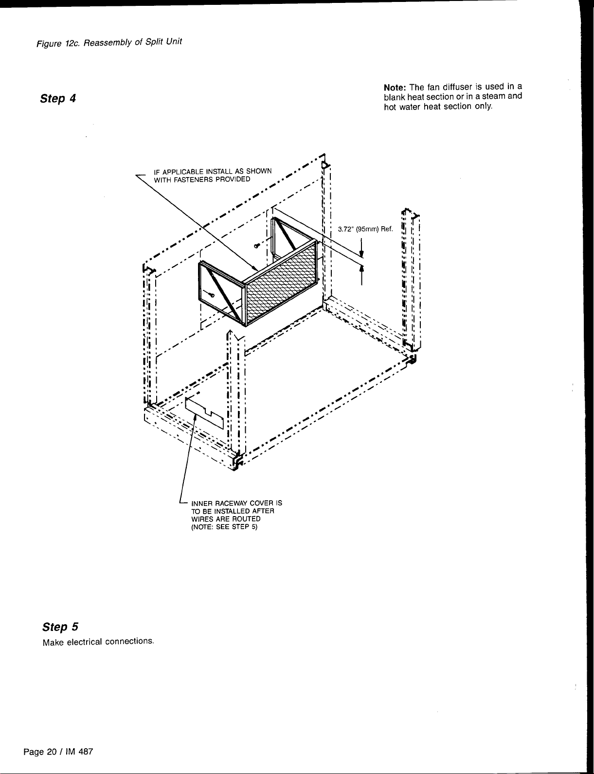
Figure 12c. Reassembly of Split Unit
Step 4
Note: The fan diffuser is used in a
blank heat section or in a steam and
hot water heat section only.
A
Step 5
Make electrical connections.
Page 20 I IM 487
~ INNER RACEWAY COVER IS
TO BE INSTALLED AFTER
WIRES ARE ROUTED
(NOTE: SEE STEP 5)
Page 21
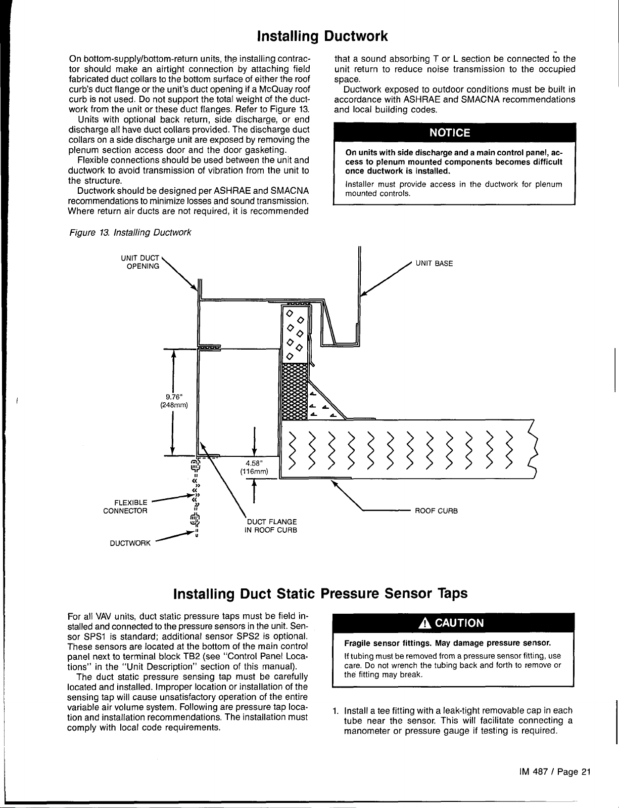
Installing
Ductwork
On bottom-supply/bottom-return units, the installing contractor should make an airtight connection by attaching field
fabricated duct collars to the bottom surface of either the roof
curb’s duct flange or the unit’s duct opening if a McQuay roof
curb is not used. Do not support the total weight of the ductwork from the unit or these duct flanges. Refer to Figure 13.
Units with optional back return, side discharge, or end
discharge all have duct collars provided. The discharge duct
collars on a side discharge unit are exposed by removing the
plenum section access door and the door gasketing.
Flexible connections should be used between the unit and
ductwork to avoid transmission of vibration from the unit to
the structure.
Ductwork should be designed per ASH RAE and SMACNA
recommendations to minimize losses and sound transmission.
Where return air ducts are not required, it is recommended
Figure 13. Installing Ductwork
UNIT DUCT
OPENING
\ll
that a sound absorbing T or L section be connected tO the
unit return to reduce noise transmission to the occupied
space.
Ductwork exposed to outdoor conditions must be built in
accordance with ASH RAE and SMACNA recommendations
and local building codes.
On units with side discharge and a main control panel, access to plenum mounted components becomes difficult
once ductwork is installed.
Installer must provide access in the ductwork for plenum
mounted controls.
I
UNIT BASE
/
I
T‘
9.76”
(248mm)
I
CONNECTOR
For all VAV units, duct static pressure taps must be field installed and connected to the pressure sensors in the unit. Sensor SPSI is standard; additional sensor SPS2 is optional.
These sensors are located at the bottom of the main control
panel next to terminal block TB2 (see “Control Panel Locations” in the “Unit Description” section of this manual).
The duct static pressure sensing tap must be carefully
located and installed. Improper location or installation of the
sensing tap will cause unsatisfactory operation of the entire
variable air volume system. Following are pressure tap location and installation recommendations. The installation must
comply with local code requirements.
fi’
Ii!,$
Installing
\
.DUCT FLANGE
IN ROOF CURB
Duct Static Pressure Sensor Taps
~ ROOF CURB
Fragile sensor fittings. May damage pressure sensor.
If tubing must be removed from a pressure sensor fitting, use
Do not wrench the tubing back and forth to remove or
care.
the fitting may break.
1. Install a tee fitting with a leak-tight removable cap in each
tube near the sensor. This will facilitate connecting a
manometer or pressure gauge if testing is required.
IM 487 / Page 21
Page 22

2.
Use different colored tubing for the duct pressure (Hi) and
reference pressure (LO) taps, or tag the tubes.
Locate the duct pressure (Hi) tap near the end of a long
3.
duct to ensure that all terminal box take-offs along the run
will have adequate static pressure.
4.
Locate the duct tap in a nonturbulent flow area of the duct.
Keep it several duct diameters away from take-off points,
bends, neckdowns, attenuators, vanes, or other irregulari-
ties.
5.
Use a static pressure tip (Dwyer A302 or equivalent) or the
bare end of the plastic tubing for the duct tap. (If the duct
is lined inside, use a static pressure tip device.)
6.
Install the duct tap so that it senses only static pressure
(not velocity pressure). If an L-shaped pressure tip device
is used, the point must face the airstream. If a bare tube
end is used, it must be smooth, square (not cut at an
angle), and perpendicular to the airstream (see Figure 14).
7.
Locate the reference pressure (LO) tap somewhere near
the duct pressure tap within the building (see Figure 14).
If the reference tap is not connected to the sensor, un-
satisfactory operation will result.
8.
Route the tubes between the curb and the supply duct,
and feed them into the unit through the knockout in the
bottom of the control panel (see Figure 15). Connect the
tubes to the appropriate 1/4inch fittings on the sensors.
Assure that the sensors do not support the weight of the
tubing; use tube clamps or some other means.
14. Duct Static Pressure Tap Installation
Figure
TO SENSOR
TO SENSOR
“LO” INPUT
RUBBER
TUBE CLA
PRESSU
TUBING
TUBING EXTENDS ~
THRU APPROX, 1~”
ROMMET
Installing Building Static Pressure Sensor Taps
If a unit has direct building static pressure control capability,
static pressure taps must be field installed and connected to
pressure sensor SPS2 in the unit. This sensor is located at
the bottom of the main control panel next to terminal block
TB2 (see “Control Panel Locations” in the “Unit Description”
section of this manual).
The two static pressure sensing taps must be carefully
located and installed. Improper location or installation of the
sensing taps will cause unsatisfactory operation. Following
are pressure tap location and installation recommendations
for both building envelope and lab, or “space within a space;’
pressure control applications. The installation must comply
with local code requirements.
Fragile sensor fittings. May damage pressure sensor.
If tubing must be removed from a pressure sensor fitting, use
care. Do not wrench the tubing back and forth to remove or
~
Building Pressurization Applications
1.Install a tee fitting with a leak-tight removable cap in each
tube near the sensor. This will facilitate connecting
manometer or pressure gauge if testing is required.
Figure 15. Static Pressure Tubing Entrance Locations
Locate the building pressure (Hi) tap in the area that re-
2.
quires the closest control. Typically, this is a ground level
floor that has doors to the outside.
Locate the building tap so that it is not influenced by any
3.
source of moving air (velocity pressure). These sources
may include air diffusers or outside doors.
4.
Route the building tap tube between the curb and the
supply duct, and feed it into the unit through the knockout
in the bottom of the control panel (see Figure 15). Connect the tube to the 1/4 inch HI fitting on sensor SPS2.
Assure that the sensor does not support the weight of the
tubing; use tube clamps or some other means.
Locate the reference pressure (LO) tap on the roof. Keep
5.
it away from the condenser fans, walls, or anything else
that may cause air turbulence. Mount it high enough above
the roof so that it is not affected by snow. If the reference
tap is not connected to the sensor, unsatisfactory operation will result.
6.
Use an outdoor static pressure tip (Dwyer A306 or
equivalent) to minimize the adverse effects of wind. Place
some type of screen over the sensor to keep out insects.
Loosely packed cotton works well.
7.
Route the outdoor tap tube out of the main control panel
a
through a small field-cut opening in the edge of the control wiring raceway cover (see Figure 15). Cut this “mouse
hole” in the vertical portion of the edge. Seal the penetra-
WIRING
COVER
\
Page 22 / IM 487
Page 23

tion to prevent water from entering, Connect the tube to 4,
L
inch LO fitting on sensor SPS2.
the 1/4
Lab Pressurization Applications
1.
Install a tee fitting with a leak-tight removable cap in each
tube near the sensor. This will facilitate connecting a
manometer or pressure gauge if testing is required.
2.
Use different colored tubing for the controlled space 6
pressure (Hi) and reference pressure (LO) taps, or tag the
tubes.
Regardless of whether the controlled space is positive or 7.
3.
negative with respect to its reference, locate the HI pres-
sure tap in the controlled space. (The setpoint can be set
between -0.2 and 0.2” W.C. [-50 and 50 Pa])
Locate the reference pressure (LO) tap in the area sur-
rounding the controlled
connected to the sensor, unsatisfactory operation will
result.
5.
Locate both taps so that they are not influenced by any
source of moving air (velocity pressure), These sources
may include air diffusers or doors between the high and
low pressure areas.
Route the tap tubes between the curb and the supply duct,
and feed them into the unit through the knockout in the
bottom of the control panel (see Figure 15).
Connect the tubes to the appropriate 1/4 inch fittings on
SPS2. Assure that the sensor does not support me
sensor
weight of the tubing; use tube clamps or some other
means,
space. If the reference tap is not
. .
Condensate Drain
The unit is provided with a 1.50” male NPT condensate drain
connection. Refer to certified drawings for the exact location.
The unit and drain pan must be level side to side and a Ptrap must be installed for proper drainage.
RAH units may have positive or negative pressure sections.
It is recommended that traps are used in both cases with care
given to negative pressure sections. In Figure 16, dimension
“A” should be a minimum of 8“ (203mm). As a conservative
measure to prevent the cabinet static pressure from blowing
or drawing the water out of the trap and causing air leakage,
dimension “A’ should be two times the maximum static
sure encountered in the coil section in inches W.C.
Drainage of condensate directly onto the roof may be acceptable; refer to local code. It is recommended that a small
drip pad of either stone, mortar, wood or metal be provided
to protect the roof against possible damage.
If condensate is to be piped into the building drainage
system, the drain line should be pitched away from the unit
at a minimum of 1/8” per foot (3mm per 254mm). The drain
line must penetrate the roof external to the unit, Refer to local
codes for additional requirements. Sealed drain lines require
venting to assure proper condensate flow.
Figure 16. Condensate Drain Connection
STATIC PRESSURE P, IN W.C.
pres-
Connection
Where the cooling coils have intermediate condensate pans
on the face of the evaporator coil, copper tubes near both
ends of the coil provide drainage to the main drain pan, Check
that the copper tubes are in place and open before the unit
is put into operation.
On units with staggered cooling coils, the upper drain pan
drains into the lower coil drain pan through a copper tube near
the center of the drain pan, Check that this tube is open before
putting the unit into operation and as part of routine maintenance.
Because drain pans in any air conditioning unit may have
some moisture in them, algae, etc. will grow, Periodic cleaning is necessary to prevent this build-up from plugging the
drain and causing the drain pan to overflow, Also, the drain
pans should be kept clean to prevent the spread of disease.
Cleaning should be performed by qualified personnel.
Biological hazard. May cause disease.
Cleaning should be performed by qualified personnel.
I
T’
4“ (102mm)
MINIMUM
T
“A”
(8” [203mm] MINIMUM
OR2XP)
t
DRAIN PAN
VIEW A
L
--ii
NOTE: DRAIN LINE MUST
NOT BE RUN HIGHER
THAN THIS LEVEL.
((
II
MINIMIZE THIS
DIMENSION
““’ 3
\\\
\
VIEW ‘W’
4
- COPPER TUBE
(ONE EACH END OF COIL)
IM 487 I Page 23
Page 24

Field Refrigerant Piping and Charging of DX Coils
RAH units that ship from the factory with DX coils installed
do not include refrigerant piping or refrigerant controls. The
coil assembly is ready for field connections at the distributors
and at the suction headers. Piping kits that provide the
necessary liquid and hot gas piping and control components
are available for field installation.
Field installed refrigerant piping may exit the unit cabinet
at one of the following locations:
1. Through the floor of the unit.
2. Through the discharge and bulkhead of the unit.
3. Through a cabinet door near the DX coil that is not required
for service areas.
Caution: For any of the above cabinet penetrations, the hole
must be tightly sealed to prevent water or air leakage.
In preparing for field piping, the plastic plugs on the distribu-
tors must be removed and the copper caps at the suction
header connections must be unsweated.
Piping design, sizing, and installation information presented
in ASH RAE handbooks should be followed in the design and
installation of interconnecting piping. The DX coil and condensing unit are intended to be set at the same elevation,
as close as possible to each other to minimize refrigerant
pressure drop. The piping must be designed and installed to
prevent liquid refrigerant carryover to the compressor and to
assure a continuous return of compressor oil from the system.
5.
Suction lines within the unit cabinet must be insulated to
prevent dripping of condensation.
6.
The liquid line should be sized for a pressure drop not to
exceed the pressure equivalent of 20F (-17C) for R-22 (6
psi [41 kPa]) saturated temperature. The RAH unit includes
a factory installed filter-drier, solenoid valve, and sightglass
in each liquid line, upstream of the thermal expansion
valve,
Table 4. Minimum Tonnage (R-22) to Carry Oil L@ Suction
Riser at 40 OF Saturated Suction
Line Size
O.D. (In.)
Minimum
Tons
Note: When compressor minimum tonnage is less than shown in the above
table for a given line size, double suction risers will be required.
11A
1,50
13h
2.50
15h
3.80
2% 2%
7.60
13.10
31A 35h
20.4
41~
29.7 41.3
Leak Testing
The field piping system should be checked for leaks prior to
charging. Leak testing must be performed to current EPA
standards and regulations. After making any necessary re-
pair, the system should be evacuated as described in the
following paragraphs.
The pounds of refrigerant in the system may exceed the
capacity of the condenser, depending on the amount of
refrigerant in the liquid lines between the DX coil and the
condensing unit. Refer to condenser manufacturer for information about refrigerant capacity. Suitable means of
containing the refrigerant is required.
On systems with optional hot gas bypass, it is important
the bypass solenoid valve be located at the condensing
unit and not at the DX coil to prevent liquid return and
~
Piping Recommendations
1. Use type K or L clean copper tubing. All joints should be
thoroughly cleaned and brazed with high temperature
solder.
2. Piping sizes should be based on temperature/pressure
limitations as recommended in the following paragraphs.
Under no circumstances should pipe size be based strictly upon the coil or condensing unit piping connection size.
3. Suction line piping pressure drop should not exceed the
pressure equivalent of 2° F (-17C) for R-22 (3 psi [21 kPa])
per 100 feet (30.5m) of equivalent pipe length. After the
suction line size has been determined, the vertical suction risers should be checked to verify that oil will be car-
ried up the riser and back to the compressor. The suction
line(s) should be pitched in the direction of refrigerant flow
and fully insulated between the evaporator(s) and the
compressor.
4. Vertical suction risers should be checked using Table 4
to determine the minimum tonnage required to carry oil
up suction risers of various sizes.
A serious explosion could result from using oxygen to
build up pressure resulting in severe personal injury or
death.
I Do not use oxygen to build up pressure.
Evacuation
After it has been determined that the unit is tight and there
are no refrigerant leaks, the system should be evacuated. The
use of a vacuum pump with a pumping capacity of approximately 3 cu. ft./rein. (1.4 L/see.) and the ability to reduce the
vacuum in the unit to at least 1 millimeter (1000 microns) is
recommended.
A mercury manometer or an electronic or other type of
1.
micron gauge should be connected to the unit at a point
remote from the vacuum pump. For readings below 1
millimeter, an electronic or other micron gauge should be
used.
2.
The triple evacuation method is recommended and is particularly helpful if the vacuum pump is unable to obtain
the desired 1 millimeter of vacuum. The system is first
evacuated to approximately 29 inches (737mm) of mercury.
Enough refrigerant vapor is then added to the system to
bring the pressure up to O pounds.
Then the system is once again evacuated to 29 inches
3.
(737mm) of vacuum. This procedure is repeated three
times. This method can be most effective by holding system
pressure at O pounds for a minimum of 1 hour between
evacuations. The first pulldown will remove about 90% of
the noncondensables, the second about 90% of that re-
maining from the first pulldown, and after the third, only
1/10 of 1% noncondensables will remain.
I
Page 24 I IM 487
Page 25

Table 5 below shows the relationship between pressure, microns, atmospheres, and the boiling point of water.
Table 5. Pressure-Vacuum Equivalents
Absolute Pressure Above Zero
Microns
o 0 760.00
50 0.001
100
150 0.003 759.85
200 0,004 759.80
300
500 0.009
1,000 0,019
2,000 0.039
4,000 0.078
6,000 0.117
8,000 0.156
10,000 0.193
15,000 0.290
20,000
30,000
50,000
100,000
200,000
500,000
E==
7Gr-1 mm
EB=t
Vacuum Below one Atmosphere
Psia
0.002
0.006 759.70
0.387
0.580
Mercury
(mm)
759.95
759.90
759.50
759.00
758.00
756.00
754.00
752.00
750.00
745.00
740.00
730.00
710.00
660.00
560.00
260.00
n o
Mercury
(Inches) One Atmosphere
29.921
29.920
29.920 117,600
29.920 1/5,100
29.910 113,800
29.910 112,500
29.900 Ill ,520
29.880
29.840
29.760
29.690
29.600 1/95
29.530 1176
29.330
29.130 1138
28.740 1125
27.950
25.980 2115
22.050
10.240 2/3
Approximate Boiling
Fraction of of HzO at Each
—
CJnn
,L””
1/15,:
11760
11380 15 (-9”C)
1/169 29 (-2°C)
1/127 39 (4” c)
1/50 63 (170C)
1/15
114
1 Atmosphere 212 (loo”c)
Pressure 0F (0 C)
1
Point
– W-1 (. A6. C)
=- , ,- -,
-40 (-40” C)
-33 (-36 ‘C)
-28 (-33° C)
-21 (-29oC)
-12 (-240C)
1 (-17” C)
46 (80C)
52 (I IoC)
72 (220C)
84 (29oC)
101 (380C)
125 (52” C)
152 (67”C)
192 (89oC)
—
I
Charging the System
1.
After all refrigerant piping is complete and the system has
been evacuated, it can be charged as described in the
paragraphs following. Connect the refrigerant drum to the
gauge port on the liquid shutoff valve, and purge the charging line between the refrigerant cylinder and the valve.
I
Then open the valve to the midposition.
2.
If the system is under a vacuum, stand the refrigerant drum
with the connection up, open the drum and break the
Note: It is
circuit be stamped on the unit nameplate for future reference.
Refrigerant Charge
Factory installed DX coils in RAH units are designed for use
with R-22. The total system charge is the sum of three values:
1. Condensing unit charge—refer to manufacturer’s data.
2. Evaporator coil charge—refer to Table 6.
3. Charge for length of interconnecting piping installed by
vacuum with refrigerant gas.
With a system gas pressure higher than the equivalent
3.
of a freezing temperature, invert the charging cylinder and
elevate the drum above the condenser. With the drum in
this position and the valves open, liquid refrigerant will flow
into the condenser. Approximately 75% of the total requirement estimated for the unit can be charged in this manner.
4.
After 75% of the required charge has entered the condenser, reconnect the refrigerant drum and charging line
to the suction side of the system. Again purge the connecting line, stand the drum with the connection side up, and
place the service valve in the open position.
Important: At this point, the charging procedure should be
interrupted and prestart checks made before attempting to
complete the refrigerant charge.
Note: Factory installed DX coils are intended for two refriger-
ant circuits containing identical weights of refrigerant. The
values shown in Tables 6 and 7 are for each circuit.
Note: The total operating charge per circuit should not ex-
ceed the pumpdown capacity per circuit, specified by the condensing unit manufacturer.
Table 6. Approximate DX Coil Refrigerant Charge Per Circuit
Unit DX Coil R-22 Chsrge (Lbs./Circuit)
Size
047C 3x No. Of DX ROWS
077C
recommended that the total operating charge per
field—refer to Table 7.
Flat Coil
5 x No. of DX flOWS 6.5 X No. Of DX ROWS
Staggered Coil
3.5 x No. of DX flowS
Table 7. Weight of Refrigerant R-22 in Copper Lines (Pounds Per 100 Feet of Type L Tubing)
O.D. Line Size
%
V2 0.100 7.12
518
‘/8
11/s
1% 0.872
15/8 1.237
27/s
278
3% 4.728
35/, 6,398 456.0 24.000
41~
Volume Per 100 Feet
in Cubic Feet
0.054 3.84 .202 .052
0.162 7,12 .605 .158
0.336 24.0 1.260
0.573 40.8 2.140
2.147 153.0 8.040
3.312 236.0 12.400
8.313 592.0 31.100
Liquid @ 100” F
62.1 3.260
88.0 4.620
336,0 17.700
Weight of Refrigerant, Lbs./100 Feet
Hot GSS @ 120” F Suction Gaa (Superheated to 85” F)
Cond.
.374 .098 .143
20” F 40” F
,323 .480
.550 .820
.839 1.250
1.190 1.770
2.060
3.180
4.550
6.150 9.140
8.000
.077
.232
3.060
4.720
6.750
11.190
IM 487 / Page
25
Page 26

Unit Piping
Gas Piping
See the “installation” section of the gas fired furnace installation manual, Bulletin No. IM 484.
Piping for Steam, Hot WateR
and Chilled Water Coils
Factory installed chilled water coils are installed in a combina-
tion coil section which is also designed to accept a factory
installed heating coil immediately upstream. The combination
coil section may be ordered in either the draw-through or blowthrough position. All chilled water piping can be done inter-
nal to the unit without requiring a piping vestibule.
Steam and hot water coils may be factory installed in either
a heat section, or in the combination coil section. These sections may be located either in the draw-through or blowthrough position. When a steam or hot water coil is installed in
the heat section, all piping may be done internal to the unit
without requiring a piping vestibule. Refer to Figures 17 and
18.
When a steam or hot water coil is installed in the combination coil section, the coil connections project to the inside surface of the door panel. Holes maybe cut in the door panels for
the piping to be connected to the coils, or an accessory piping
vestibule may be added to the unit to provide piping space.
Refer to the section on vestibule assembly instructions. The
piping may then be routed back within the unit as shown in
Figure 17.
To avoid piping penetrations through the roof external to the
curb, holes may be cut through the floor of the unit at the locations specified on the certified drawings. Caution; All holes
in the unit floor must be sealed to prevent water leakage into
the building.
Coil freeze possible. ,May damage equipment.
Carefully read instructions for mixing antifreeze solution used. Some products will have higher freezing points in their
natural state than when mixed with water. The freezing of coils
is not the responsibility of McQuay International.
Refer to “Winterizing Coils” in the “Maintenance” section of
the manual.
valve. Field piping connections are of the same NPT size as
the valve—male threads at the supply connection, female
threads at the return connection.
Note: The valve actuator spring returns to a stem down position upon power failure. This allows full flow through the coil.
Figure 17 Hot Water Heat Section
(Shown With Factory Valve and Piping)
SUPPLY
Steam Piping (All Units)
The steam heat section consists of two stacked coils (pitched
at 1/8“ per foot [3mm per 30cm]), as shown in Figure 18. When
no factory piping or valve is included, the coil connections
are 2.50” male NPT iron pipe.
Refer to the sections on steam coil piping and trap recom-
mendations for additional information.
Figure 18. Steam Heat Section
(Shown With Factory Valve and Piping)
Hot Water Piping (All Units)
Note: If an iron valve is installed
in the unit, connecting to a
copper piping system will likely cause galvanic corrosion to
occur and the valves will not last. All coils have vents and
drains factory installed.
Hot water coils are not normally recommended for use with
entering air temperatures below 40 F (40C), No control
system can be depended on to be 100% safe against freezeUP with water coils. Glycol solutions or brines are the only
freeze-safe media for operation of water coils for low entering air conditions. Refer to the “Maintenance” section of this
manual for more on winterizing coils. The hot water section
consists of two stacked coils, as shown in Figure
no factory piping or valve is included, the coil connections
are 2.12” ODM copper.
Hot Water Piping to Coils in the Heat Section
Hot water coils are provided without valves for field piping, or
piped with three-way valves with actuator motors.
With the factory piping and valve package, the two coils are
piped in parallel and controlled through a single three-way
Page 26 I IM 487
17. When
Page 27

Steam Piping to Coils in the Heat Section
Steam coils are provided without valves for field piping, or
piped with two-way valves and actuator motors.
With the factory piping and valve package, the two coil supplies are piped in parallel and controlled through a single twoway valve. The field supply connection is of the same female
NPT size as the valve. Field return connections are made at
the 2.50” male NPT fittings on each of the two stacked coils.
Note: The valve actuator spring returns to a stem up posi-
tion upon power failure. This allows full flow through the coil.
Pipinq Recommendations (Steam Coils)
1.”
Be-certain that adequate piping flexibility is provided.
Stresses resulting from expansion of closely coupled pip-
ing and coil arrangement can cause serious damage.
2.
Do not reduce pipe size at the coil return connection. Carry
return connection size through the dirt pocket, making the
reduction at the branch leading to the trap.
3.
It is recommended that vacuum breakers be installed
all applications to prevent retaining condensate in the coil.
Generally, the vacuum breaker is to be connected between
the coil inlet and the return main. However, if the system
has a flooded return main, the vacuum breaker should be
open to the atmosphere and the trap design should allow
venting of the large quantities of air.
Do not drain steam mains or take-offs through coils. Drain
4.
mains ahead of coils through a steam trap to the return line.
Do not attempt to lift condensate when using modulating
5.
or on-off control.
Pitch all supply and return steam piping down a minimum
6.
of 1 inch per 10 feet (3mm per 305cm) in direction of flow.
Steam Trap Recommendations
1.
Size traps in accordance with manufacturers’ recommendations. Be certain that the required pressure differential
will always be available. Do not undersize.
2
Float and thermostatic or bucket traps are recommended
for low pressure steam. Use bucket traps on systems with
on-off control only.
Locate traps at least 12 inches (305mm) below the coil
3.
return connection.
4.
Always install strainers as close as possible to the inlet side
of the trap.
!5.
A single trap may generally be used for coils piped in
parallel, but an individual trap for each coil is preferred.
Freeze Conditions (Steam Coils)
(Entering air temperature below 350 F [20 C])
1. 5 PSI (34.5 kPa) steam must be supplied to coils at all
times.
2. Modulating valves are not recommended. Control should
be by means of face and bypass dampers.
As additional protection against freeze-up, the trap should
3.
be installed sufficiently far below coil to provide an adequate hydrostatic head to ensure removal of condensate
during an interruption on the steam pressure. Estimate 3
feet (914mm) for each 1 PSI (6.9 kPa) of trap differential
required.
4.
If the unit is to be operated in environments with possible
freezing temperatures, an optional freezestat is recom-
mended. Refer to “Freeze Protection” in the “Unit Options”
section of this manual.
Chilled Water Piping
on
Chilled water coils are provided without valves for field piping, or piped with three-way valves with motor actuators. Table
8 provides information on units with factory installed piping
and valve packages. The table also provides field sweat connection information for units not furnished with factory installed
piping and valve packages.
With the factory piping and valve package, the coil assembly
is controlled through a single three-way valve. When two coils
are included in the assembly, they are piped in parallel. Field
connections are male NPT, sized as shown in Table 8. Refer
to Figure 20 for a typical cooling coil with factory valve and
piping.
Fiaure 20. Chilled Water Coil
(Shown With Factory Valve and Piping)
Figure 19. Heating Coil Piping With Vestibule
IM 487 I Page 27
Page 28
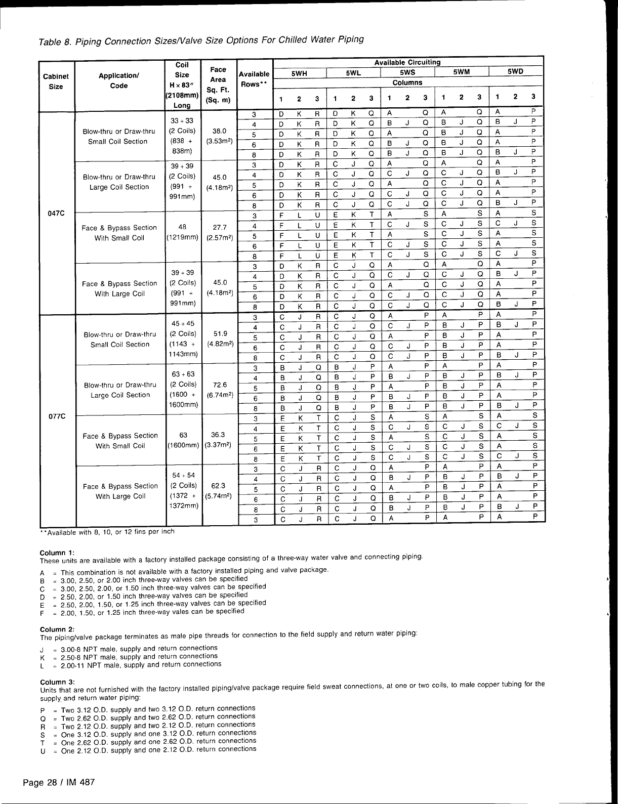
Table 8. Piping Connection SizeslValve Size Options For Chilled Water Piping
:abinet
Size
047C
077C
“Available with 8, 10, or 12 fins per
Application/
Code
Blow-thru or Draw-thru
Small Coil Section
Blow-thru or Draw-thru
Large Coil Section
Bypass Section
Face &
With Small Coil
Face & Bypass Section
With Large Coil
Blow-thru or Draw-thru
Small Coil Section
Blow-thru or Draw-thru
Large Coil Section
Face & Bypass Section
With Small Coil
Face & Bypass SeCtiOn
With Large Coil
y
Hx83° i
2108mm)’
Long
33+ 33
(2 Coils)
(838 +
838m)
39+ 39
(2 Coils)
(991 +
991 mm)
48
1219mm)
39+ 39
(2 Coils)
(991 +
991 mm)
45
45+
(2 Coils)
(1143 +
1143mm)
63+ 63
Coils)
(2
(1600 +
1600mm)
63
1600mm)
54+ 54
(2 Coils)
(1372 +
1372mm)
Face
Available
Area
Sq. Ft.
(Sa. m)
(3.53mZ)
(4.18mZ)
(2.57m2)
(’$18M2)
(4.82m2)
(6.74m2)
3.37mZ)
Rows*”
3
38.0
45.0
27.7
45.0 “~KRICJQ 1A
51.9
72.6
36.3
4
5
6
8
3
4
5
6
8
3
4
5 FLU
6
8
m
?.
I A nKRICJQ CJQ
~lDKRICJQICJ ;l;~QIA
3
4 CJR CJQIC
; ~JR
8
3
4
5
~
8
“ r ,/ T PI
4
5
6
8
3
5WH
123 123 1z3
DKR DKQ A
DKR DKQ
DKR DKQ A
DKR DKQ
DKR
DKR CJQ A
DKR CJQ
DKR
DKR
DKR CJQ
FLU EKT A
FLU EKT
FLU EKT
FLU EKT cJs cJs CJS
I DKRICJ
,
CJR cJQ IA
JR CJI
CJR CJQ
BJQ BJp A
BJQ BJp B
BJQ BJp A
BJQ BJp
BJQ BJ
,,,
.
EKTICJS
EKTICJS A
K
E
EKTICJS
CJRICJQ A
5WL
DKQ BJQ BJQ BJP
CJQ A
CJQ cJQ CJQ A
EKT
RIC
TICJ
J
CJQ
I
r. Ic. IRIc JQIBJ PIBJp BJP
62.3 ; ;;
:5.74mZ)
6
8
3
CJR CJQ
CJR CJQ
CJR CJQ A
RICJQIA
Available Circuiting
5WS
Columns
5WM
123 123
Q A
Q A
BJQ BJQ BJP
Q BJQ A
BJQ BJQ A
Q A
Q A
cJQ cJQ BJF’
Q CJQ A
CJQ CJQ BJP
s A
s A
cJs cJs CJS
A
s CJS A
cJs cJs A
Q A
QIC
Q A
cJQ BJP
n c
1
CJ
Q A
.1
Q A
cJ
BJ
BJ
-,
cJsl(
SICJ
sIc JSICJS IA
cJs[~Js!c L
A “1.
rim
PIBJP A
BJP BJ
BJP BJPIBJP
P A
P A
P A P
PIA
5WD
P
P
P
P
P
P
s
s
s
P
P
‘1
1
I
s
I .s
~
P
P
,.
1
1
P
Column 1:
These units are available with a factory installed package consisting of a three-way water valve and connecting piping.
A = This combination is not available with a factory installed piping and valve package.
B = 3.00, 2.50, or 2.00 inch three-way valves can be specified
C = 3.00, 2.50, 2.00, or 1.50 inch three-way valves can be specified
D = 250, 2.00, or 1.50 inch three-way valves can be specified
E = 2.50, 2.00, 1.50, or 1.25 inch three-way valves can be specified
F = 2.00, 1.50, or 1.25 inch three-way vales can be specified
Column 2:
The pipinglvalve package terminates as male pipe threads for connection to the field supply and return water piping:
3.00-8 NPT male, supply and return connections
J=
K = 2.50-8 NPT male, supply and return connections
L = 2.00-11 NPT male, supply and return connections
Column 3:
Units that are not furnished with the factory installed piping/valve package require field sweat connections,
supply, and return water pipin9:
P = Two 3.12 O.D. supply and two 3.12 O.D. return connections
Q = Two 2.62 O.D. supply and two 2.62 O.D. return connections
R = Two 2.12 O.D. supply and two 2.12 O.D. return connections
S = One 3.12 O.D. supply and one 3.12 O.D. return connections
T = One 2.62 O.D. supply and one 2.62 O.D. return connections
U = One 2.12 O.D. supply and one 2.12 O.D. return connections
Page 28 I IM 487
at one or two coils, to male copper tubing for the
Page 29

Vestibule Assembly Instructions
An accessory vestibule is available to provide additional pip-
ing space forcoils installed in a four-foot section. A vestibule
is required to maintain door access on a combination heating
and cooling section. The vestibule should be assembled to
the unit part by part as shown in Figure 21. Note: The door,
hinge, and latch assemblies from the unit are used on the
vestibule.
Step 1
Remove door from section where vestibule is to be located
by removing screws holding hinges to upright support (leave
hinges on door). Set door aside and save for Step 4.
Remove door latch assembly from other side upright support. Use offset Phillips screwdriver or a wrench to remove
screws holding latch assembly in place. Save door latch
assembly, screws and bushings for Step 4.
Figure 21a.
\
.
.
\
1.
I
Step 2
Remove gasketing around door flange and save for use on
vestibule. See Step 4. Remove door and save for Step 4.
- DOOR
Figure 21b.
w
DOOR LATCH ASSEMBLY
\
GASKET1NG
OOORPROP
/
IM 487 I Page 29
Page 30

I
~
Step 3
Assemble side panels A and B to uprights using #10 drill
1.
screws supplied. Make certain side panels are flush
against uprights before securing into place.
2.
Fasten bottom panel D to base channel using #10 drill
screws and to side panels A and B using #10 screws
supplied.
Set top panel C in place and fasten to side panels A and
3.
B using #10 screws and to top panel using
supplied.
#10 screws
Figure 21c. ~
I
<:
‘1 0 SCREW
. ..\
/,”’
010 DRILL
.. ..
. .
...
...
/.”
,.,
,,,
..~
SCREW
“..
‘. ...
.:>
,,,
,..
,.,
7
r
Step 4
1.Reassemble access door to vestibule by screwing hinges
into side panel using screws saved from Step 1. (Access
door must be attached to the vestibule in the same opening direction as it was on the unit.)
2. Remove and discard latch handle locking screws and retaining washer. Fasten door latch assembly to side panel
using screws and bushings saved from Step 1. (Latch must
be fastened on the same side as when located on the unit.)
3. Fasten upright angles to vestibule using #10 screws
supplied.
4. Seal between unit and vestibule with silicone sealant along
top and sides as shown.
Note: Any holes cut in the floor of the unit must be sealed
to prevent water leakage.
Figure 21d.
UPRIGHT ANGLE
‘1 0 SCREW
I
\ /i
— ., 0 SCREW
----
S[ LI CONE
SEIIL~NT
4
%
Page 30 / IM 487
\
/“
G~SKETI NC>
iuPtN GHT 14NGLE
\\
Page 31

Damper Assemblies
I
The optional damper assemblies described in this section are
provided with manually adjustable linkages, or maybe shipped with factory installed actuators and linkages in units that
include factory controls.
Economizer Dampers
Outside air intake is provided on both sides of the unit, and
the return air path is at the center of the damper set. As the
single actuator modulates the outside air dampers open, the
return air dampers close. Exhaust air exits the unit through
the gravity relief dampers provided at the end of the
economizer section.
Figure 22a. Figure 22b.
OUTSIDE
AIR
Q /’ ,“ - ‘cONOM1zER
- OPTIONAL RETURN AIR FAN
,
_-–r
1--11
II
/ ,,
I ____
‘-r
G
The outside air return air damper assembly (economizer)
comes with manually adjustable linkage. This adjustable linkage can also be used for connection of a damper operator.
The damper is set so that the crankarm moves through a
90-degree angle to bring the economizer dampers from full
open to full close. Mechanical stops have been placed in the
crankarm mounting bracket. Do not remove stops. If crankarm
is driven past stops, damage to linkage or damper will result.
The unit will ship with a shipping bolt securing the linkage
crankarm. Remove shipping bolt before use.
d
OUTSIDE \
AIR
Figure 22c.
,-—...-—-..-—.—..—.— ..—— . .
OA CLOSEDX
)
/’
..
/,
\
/
\._ -__ ...L_.z.v_—_-
Note: For good airflow control, adjust linkages so damper blades do not open
beyond 70 degrees. Opening a damper blade beyond 70 degrees has little
effect on its airflow.
Do not “overclose” low leak damper blades. The edge seal should just lightly
contat the adjoining blade. The blades will lock up if they are closed so far
the seal goes over center.
~.:T; ..
1
}- -–-—--- .; J:>&- # ,
;...— .-.-~
I (~> x 1.30” (33mm) Long , ;
,.
.—— –,-+ .
.500 (13mm) Dis. Shafl ‘
/
90 . . . .
- STROKE .
. ‘,? ‘
1
&,--—...’_ . . . . — -- —-. - . .. .
/
.-—...—;
., ;$ OA OPEN ]
(,–1 -’s .25” (6mm)
‘J @
/’ 1.6 \
~ #
~@
--->
(-)
IM 487 I Page 31
Page 32

Intake Hood Damper (O to 100% Outside Air)
Units requiring 100’% outside air are provided with a rain hood
and dampers which may be controlled by a single actuator.
The actuator, which may be ordered with factory controls, pro-
Figure 23a
/\..
Figure 23b
~-----
OA CLOSED ,Z sTRoKE ,, ~A OPEN
_.—
)
/’
—.. —.—
.500” (13mm) -’.75” ‘ 0
Dia.Shaft (19mm)~
Note: For good airflow control, adjust iinkages so
damper blades do not open beyond 70 degrees. Open-
ing a damper blade beyond 70 degrees has little effect
on its airflow.
Do not “overclose” low leak damper blades. The
edge seal should just lightly contat the adjoining blade.
The blades will lock up if they are closed so far the seal
goes over center.
_—. .——
/90 -’-. )
c-
--.—,
t.
)&
:>,
~‘ .25” (6m~)
‘.”.
,Q6\
-.%&+
“1
vides two position control for opening the dampers fully during unit operation and closing the dampers during the off cycle. No unit mounted exhaust dampers are provided.
.,.
.-- ._._.,
,.
Intake Hood Damper (O to 30% Outside Air)
These dampers are intended to remain at a fixed position during unit operation, providing fresh air quantities from O to 30%
of the total system airflow, depending on the damper setting.
This setting is,made at the linkage rod on units with manually adjustable linkages.
On units provided with MicroTech controls, the damper position may be set at the controller keypad. During unit operation, the two-position actuator drives the damper to the position set on the keypad. During the off cycle, the damper is
automatically closed.
No unit mounted exhaust dampers are provided with this
option.
Figure 24
I
\
\
\
!,
1,/
Ii
/
/
,
/
/
!,
L
3.15“ (80mm) MAX. STROKE OF
DAMPER LINKAGE BAR
1
Page 32 I IM 487
Page 33

Mixing Box
This section utilizes a outside air damper and a return air
damper, Use of these dampers allows outside air to be
blended with return air. Synchronized operation of the
dampers is accomplished by interconnecting rods. As one
damper section opens, the other section is being closed.
Always a total of100% CFM is drawn from this section,
Damper positioning may be either manually or automatically
adjusted. With a field installed controller, automatic operation
can be obtained,
These dampers provide a similar function to the economizer
dampers. This option differs from an economizer in that no
unit mounted exhaust dampers are provided,’
Figure 25b
Figure 25a
—
Top View of Mixing Box
I –
I .
—
—.—.—.—..
---------
.- p-q--q
Ill
Ill
;1I
II
\il 1
‘4. ; ;
l\ll
1.1
I \l
), :
I
l’\l
.1
11}
1
;1
1 1
;1
Ill
;11I
I
I 1
I
;1I1
I I
;1
Ill
.-,---, -- J-
—.—.—.—
-----
II
II
I 1
ii
11
1
II
1
!
I
II
;1
I ‘>
1
II
t
:\% ;
; \,;
1 1.,
II
1
I
I 1
\=. & ._. :
1
I
1
1
1
I
1
N
‘\
1
‘\
Note: For good airflow control, adjust linkages so damper blades do not open
beyond 70 degrees. Opening a damper blade beyond 70 degrees has little
effect on its airflow.
Do not “overclose” low leak damper blades. The edge seal should just lightly
contat the adjoining blade. The blades will lock up if they are closed so far
the seal goes over center.
OA
CLOSED
Crankarm
IM 487 I Page 33
Page 34

Face and Bypass Dampem
Face and bypass dampers are available in a flat arrangement
for use with heating coils and standard face area cooling coils,
as well as a staggered arrangement for large face area cool-
ing coils. The damper sets are linked through a jack shaft for
connection to a single actuator (factory or field installed).
Figure 26a. Flat Arrangement
t,,
DAMPER
Figure 26b.
BYPASS
DAMPER
Staggered
FACE
DAMPER
b,, 1
I
Arrangement
.~<
:>.,
< -–
11
\
/~/~\\
/’
~\\ ,,/’
/
“ \
\.
.
\
\
\
\
I /1;
‘\.,
‘.. ,
“+
/
+
$s+
e-”-
#-
..- ,’
e.e”
~-- , ,
~d’j
e~OO ,
,/”
-7’
,/
i ,- s Yi---- -- --------
]4.- ,) ‘
--/ t’ \\ i
Ill ‘1
‘\\
x.
‘;?”
/’ I
/
\
\
\l
x, I
,1
(
/’
/’
,/’
,j,’”
/’
d’
‘\,
..~”.”
,/’
i .’
\
/
,;7’
+“
\
--— .
;
\
\
‘,
.
,/
/
/’
J
/’
/“
\\
\
\
\
\
\
\
\
\’
\
\
\l
\\ :
-, \
\:
\\\,
-------
,,/
/’
f
F’
Y
+,%
-----------_=_ ~~
.,/
/
OPEN
,,’ --- go.
/
11
,$,, \\ STROKE
,;’
\\\,\\
\ \\,,
,,/
;/
.
\
/
\
“,..
\.__..
,,,, -
,,/
CLOSED’ “
\\x\\
\\\\\\
,;h,,
\
Is .@
;g$
/O
,,’
‘ 1“
.-
‘\
4
:*\
‘$, I i
3.00”
X(76mm)
J
,/”
/’
.,
-.. ,
-.
/
-.,
..
\..
\
.,
\
‘!
\
‘!
\
1
,/
i
,’
o
,,/
t
,/:
,/
/
,,’
/
Cabinet Weatherproofing
This unit ships from the factory with fully gasketed access
doors and cabinet caulking to assure weatherproof operation.
After the unit has been set in place, all door gaskets should
be inspected for shipping damage and replaced if necessary.
It is recommended the unit be protected from overhead
page 34 I IM 487
water runoff from overhangs or other structures.
Field assembled options, such as external piping vestibules
or split units, are to be recaulked per the installation instructions provided with the option.
Page 35

Electrical Installation
Field Power Wiring
Without Optional Electrical
Power Package
All of the unit side panels are hinged. Disconnect switches
and/or motor starters must not be mounted on panels which
provide access to internal components. Wiring’ conduits can
penetrate the cabinet bottom, base frame or through the hinge
and latch cap without interfering with the access panels.
Note: All holes cut into the unit must be sealed to prevent
Figure 27
/
ACCESS LATCH CAP
PANELS
l-d
= HINGE AND
TOP
water Ieakage,
Conduits connecting the unit to external panels will be subjetted to relative humitidy and air pressure differentials and
therefore should be
ing copper or other
sealed. Motor should be grounded uscorrosion resistant conductor.
t
BOTTOM
With Optional Electrical Power Package
Wiring must comply with all applicable codes and ordinances.
The warranty is voided if wiring is not in accordance with these
specifications.
According to the National Electrical Code, a disconnecting
means shall be located within sight of and readily accessible
from the air conditioning equipment. The unit may be ordered
with an optional factory mounted disconnect switch. This
switch is not fused. Power leads must be overcurrent protected
at the point of distribution. The maximum allowable overcurrent protection is shown on the unit nameplate.
RAH units may be ordered with internal power wiring for
either single or multiple point power connections. If single
point power is ordered, a single power block or an optional
disconnect switch is located within the main control panel.
Field power leads are brought into the unit through 3-inch
knockouts in the bottom of the main control panel. Refer to
Figure 28.
Units ordered with dual point power connections are pro-
vided with nonfused, factory mounted disconnect switches.
Disconnect DS1 handles the fan load and controls, and is
mounted within the main control panel. Disconnect DS3
handles the electrical heat load and is located within the elec-
tric heat control panel.
Hazardous voltage. May cause severe injury or death.
Disconnect electric power before servicing equipment. More
than one disconnect may be required to de-energize the unit,
The minimum circuit ampacity (wire sizing amps) is shown
on the unit nameplate. Refer to Table 9 for recommended
number of power wires.
Table 9. Recommended 3-Phase Power Wiring*
For MCA
UP To
(Amps)
30
40
55
70
85
95
130
150
175
200
230
255
285
310
335
380
400
460
510
570
620
670
760
765
855
930
‘To assure that disconnects and power blocks mate with power wiring
Notes:
1. All wire sizes assume separate conduit for each set of parallel conductors.
2. All wire sizes based on NEC Table 310-16 for THW wire (copper). Canadian electrical code wire ampacities may vary,
3. All wire sizes assume no voltage drop for short power leads.
Wire
Gauge
1
o“
8
6
4
3
2
1
1/0
2/0
3/0
4/0
250
300
350
400
500
3/0
5/0
250
300
350
400
500
250
300
350
Qty.1
Pole
T
=
2 75
2 75
2 75
2 75
T
2 75
2 75
2 75
3 75
*
3
3
lnsulation
Rating
(“c)
1 60
1 60
1
1 60
1 60
1
1
1 75
1 75
1 75
1 75
1 75
1 75
1 I 75
1 75
1 75
I 75
I
No. Of
:onduits
1
1
60
60
75
1
1
1
1
1
1
1
1
1
1
1
1
1
1
2
2
2
2
2
2
2
3
3
75
3
(Trsde
Size, In.)
7/2
3/4
1
I 1A
I 1/4
11~
11A
I 1/2
2
2
2
21/2
21/2
3
3
3
2
2
21/2
21/2
3
3
3
21/2
21/2
IM 487 I Page 35
Page 36

Copper wire is required for all power lead terminations at
the unit. Size wires in accordance with the ampacity tables
in Article 310 of the National Electrical Code. If long wires are
required, it maybe necessary to increase the wire size to prevent excessive voltage drop. Wires should be sized for a maximum of 3% voltage drop. Supply voltage must not vary by
more than 10% of nameplate. Phase voltage imbalance must
not exceed 2%. (Calculate the average voltage of the three
legs. The leg with voltage deviating the farthest from the
average value must not be more than 2% away.) Contact local
power company for correction of improper voltage or phase
imbalance.
Improper line voltage or excessive phase imbalance con-
stitutes product abuse. May cause severe damage to the
unit electrical components.
Assure proper
line voltage and phase balance.
Figure 28a. Power Wiring Entrance
Note: Refer to certified drawings for dimensions to wire entry points.
ELECTRIC
A ground lug is provided in the control panel for each power
conduit. Size grounding conductor
in accordance with Table
250-95 of the National Electrical Code.
In compliance with the National Electrical Code, an electrically isolated 115V circuit is provided in the unit to supply
the factory mounted service receptacle outlet and optional unit
lights. This circuit is powered by a field connected 15A, 115V
power supply. Leads are brought into the RAH unit through
a 7/8“ knockout in the bottom of the main control panel, near
the power wire entry point.
Electrical shock hazard.
May cause severe injury or death.
All protective deadfront panels must be reinstalled and secured
when power wiring is complete.
CONTROL PANEL
OISCONNE
(OPTIONAL)
‘k” KNOCKOUTS
SERVICE RECEPTACLE (QTY. 2)
FOR I15V
Figure 28b. Optional Side Power Wiring Entrance
The preferred entrance for power cables is through the bottom knockouts provided on the unit. If side entrance is the
only option, a drilling location is provided. The drilling dimensions must be followed exactly to prevent damage to the con-
trol panel. The dimensions provided are the only possible
point of side entrance for the power cables.
REMOVE LIFTING
BRACKET BEFORE
DRILLING HOLE
OCK Tel FOR 115V
EPTACLE CIRCUIT
1
II
.=”
.-”’
,,’”
.,,
a
B
A
o
.,,
,.,
,,-
,,,
,,.
.,. . ... ,
,.,’
(406mm)
4
Page 36 I IM 487
Page 37
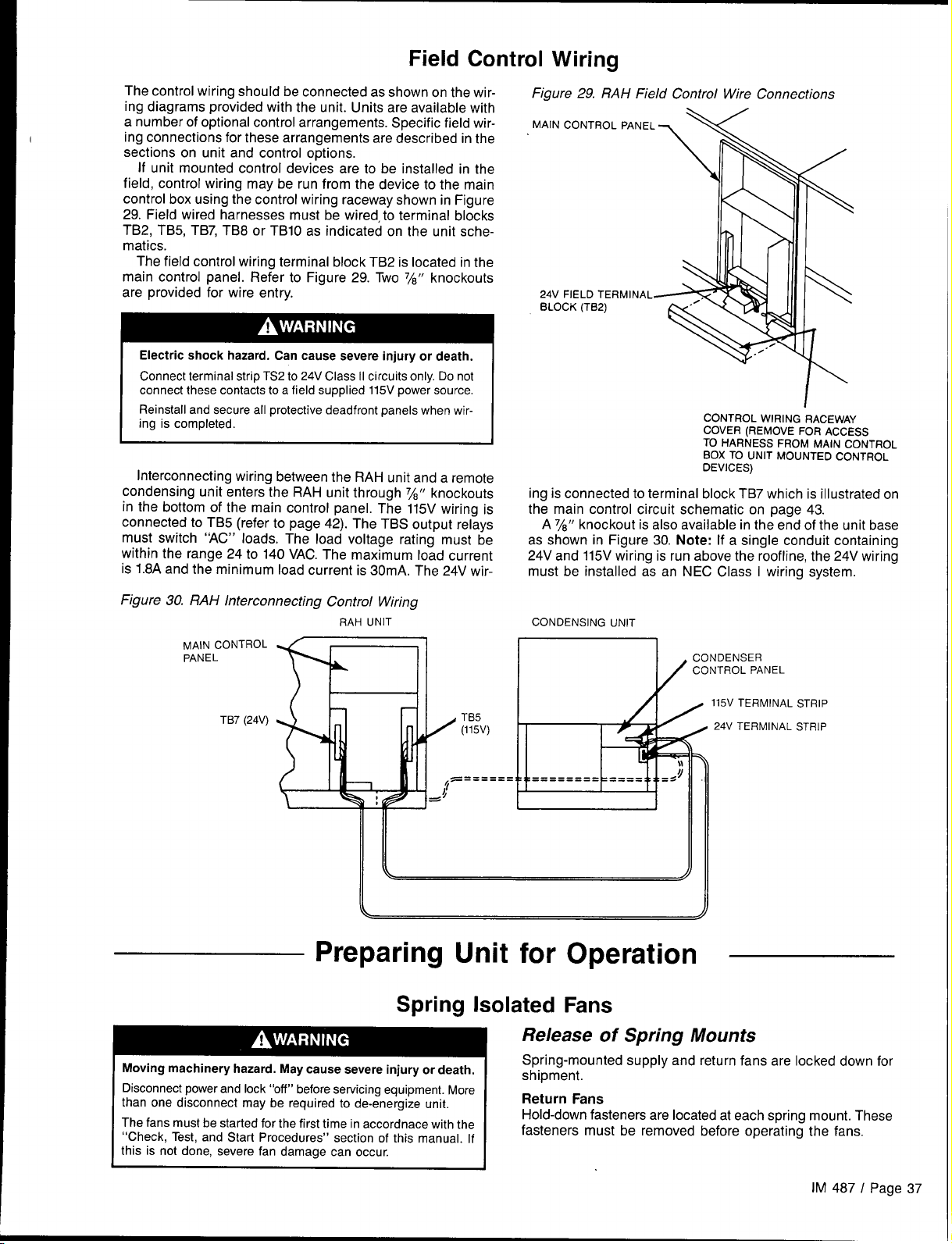
Field Control Wiring
The control wiring should be connected as shown on the wir-
ing diagrams provided with the unit. Units are available with
a number of optional control arrangements. Specific
ing connections for these arrangements are described in the
sections on unit and control options.
If unit mounted control
field, control wiring may be run from the device to the main
control box using the control wiring raceway shown in Figure
29. Field wired harnesses must be wired, to terminal blocks
TB2, TB5, TB7, TB8 or TB1O as indicated on the unit schematics.
The field control wiring terminal block TB2 is located in the
main control panel. Refer to Figure 29. Two 7/8” knockouts
are provided for wire entry.
Electric shock hazard. Can cause severe injury or death.
Connect terminal strip TS2 to 24V Class II circuits only. Do not
connect these contacts to a field supplied 115V power source.
Reinstall and secure all protective deadfront panels when
ing is completed,
Interconnecting wiring between the RAH unit and a remote
condensing unit enters the RAH unit through 7/8” knockouts
in the bottom of the main control panel. The 115V wiring is
connected to TB5 (refer to page 42). The TBS output relays
must switch “AC” loads. The load voltage rating must be
within the range 24 to 140 VAC. The maximum load current
is 1.8A and the minimum load current is 30mA. The 24V wir-
devices are to be installed in the
field wir-
wir-
Figure 29. RAH Field Control Wire Connections
MAIN CONTROL PANEL
24V FIELD TERMINAL
BLOCK (TB2)
ing is connected to terminal block TB7 which is illustrated on
the main control circuit schematic on page 43.
A 7/8” knockout is also available in the end of the unit base
as shown in Figure 30. Note: If a single conduit containing
24V and 115V wiring is run above the roof line, the 24V wiring
must be instaIled as an NEC Class i wiring system.
\v
\
11
CONTROL WIRING RACEWAY
COVER (REMOVE FOR ACCESS
TO HARNESS FROM MAIN CONTROL
BOX TO UNIT MOUNTED CONTROL
OEVICES)
Figure 30. RAH Interconnecting Control Wiring
RAH UNIT
““ONTROLm
TB7 (24V)
Preparing Unit for
Spring Isolated
Moving machinery hazard. May cause severe injury or death.
Disconnect power and lock “off” before servicing equipment. More
than one disconnect may be required to de-energize unit,
I
The fans must be started for the first time in accordnace with the
“check,
this is not done, severe fan damage can occur.
Test, and Start Procedures” section of this manual. If
CONDENSING UNIT
1
CONDENSER
CONTROL PANEL
b’
115V
TERMINAL STRIP
24V
r
,
Operation
Fans
Release of Spring Mounts
Spring-mounted supply and return fans are locked down
shinment.
.. .... ..
Return Fans
Hold-down fasteners are located at each spring mount. These
fasteners must be removed before operating the fans.
TERMINAL STRIP
for
IM 487 I Page 37
Page 38

Supply Fans
Hold-down fasteners are located
mounts on the inlet side of the fan base. A third hold-down
fastener is located on the fan base directly below the bear-
at each of the two spring
ing on the wheel side of the fan assembly. Refer to Figure 31.
Figure 32 shows a typical spring mount. Note that the 3/8“
hold-down bolt securing the fan base to the unit cross channel must be removed, as well as all 1/4” screws directly above
the spring mount.
In some arrangements, one of the 3/8“ hold-down bolts lies
below the motor base. The bolt can be reached with a 9/16”
socket and must be removed.
After removing all the hold-down fasteners, the fan assembly should be rocked by hand to check
ment.
for freedom of move-
Figure 31. Supply Fan Assembly
should run level. If not, level the assembly as follows (refer
to Figure 34):
1, With the fan off, loosen the 15/16”jam nut above the fan
base.
2. Using a large, straight blade screwdriver, turn the 5/8“ leveling screw clockwise to lower the fan base, counterclockwise to raise the fan base.
3. When properly adjusted, retighten the jam nut.
Figure 33. Thrust Restraint Adjustment
=? A
HOLD.DO
Figure 32. Spring Mount Hold-Do wn Fasteners
lM“ HOLD.DOWN SCREW
REMOVE BEFORE
RUNNING FAN
OWN
ERS
NUT ,! B!!
~ SPRING CUP
DETAIL “A”
Figure 34. Fan Spring Mount Adjustment
LEVELING SCREW ~
?..ncc I I II 1
“.”.”
cHANNEL
\
I
“_”L&4 ...
i
BULKHEAD
.. .
I
“, ,. .:.-,
“Ul,lll, ,g,
.“,
Adjustment of Supply Fan Thrust Restraints
Thrust restraints are provided when housed double-width fans
are mounted on springs. With the fan off, the adjustment
nuts should be set so the spring is slightly compressed against
the angle bolted to the fan housing frame. Refer to Figure 33.
1. With fan off, loosen jam nuts “A’.
2. Turn nut “C” until spring cup and washer contact thrust
restraint angle.
3. Turn nut “B” until spring is compressed by two turns of
nut “B”.
4. Tight jam nuts “A”.
Adjustment of Spring Mounts
During operation, all fans should ride level with the bottom
of the fan base approximately 3/8" (9mm) above the top of the
unit’s cross channel. Unhoused single-width “plug” fans will
also ride at this level when at rest.
When not operating, housed double-width fans will ride
lower at the discharge end of the fan base than at the motor
end. When the fan is operating against a static pressure, it
Page 38 I IM 487
Seismic Restraints
Spring mounted supply air and return air fans may be ordered
with factory installed seismic restraints. The system consists
of four snubbers, one located next to each spring isolator.
These snubbers will allow free movement of the fan
assemblies during normal operation because normal operation will not cause fan movements that exceed .25 inch (6mm).
However they will restrain the fan assembly and limit movement to .25 inch (6mm) in any direction if an abnormal condition were to occur.
The position the fan will assume during normal opeartion
will be determined by actual job site cfm and static pressure.
Therefore, for proper operation, the seismic restraints must
be field adjusted as part of the normal system “Check, Test,
and Start” procedure. When the fan is operating in a normal
manner there should be no contact between the snubberrestrainer angle and the neoprene bumper. However in a
“Seismic Event” the snubber will limit movement of the spring
mounted fan assembly to .25 inch (6mm) in any direction,
thereby preventing the fan from being tossed about and
damaged, or causing damage.
When a seismic restraint is properly adjusted and the fan
is operating normally, the neoprene center bumper will be
Page 39

centered within the 2 inch (51mm) diameter hole in the
restrainer angle, and the restrainer angle will be centered vertically between the flanges of the neoprene center bumper.
This results in .25 inch (6mm) clearance in all directions.
When the fan is turned off the restrainer angle may come
to rest on the neoprene center bumper.
The seismic restraint is adjustable in all directions, Vertical slots in the restrainer angle and horizontal slots in the
blower base it is bolted to allow the restrainer angle to be
adjusted up and down and back and forth. The neoprene
center bumper is mounted on a slotted hole allowing its ad-
justment in and out.
Removing the neoprene center bumper bolt allows removal,
disassembly, and replacement of the neoprene components,
Cross Section of Seismic Restraint
Snubber Restrainer Angle .-_.,
Adjust Up or
or Back and Forth
Snubber Neoprene Bumper
.25” (6mm) Gap- ~’~ t~~–~~
(Fan Running
Snubber Neoprene Bumper .––~
Down.
4“- ‘--’F
1..
-.
L...I
,,--..Ji
——
Sequences
The following sequences of operation are for a typical “C” vintage applied rooftop unit that is equipped with an economizer,
part winding fan start, a return air fan, an external time clock,
and a Remote Monitor Panel. These sequences describe the
ladder wiring diagram logic in detail; refer to the schematics
in the “Wiring Diagrams” section as you read them. Note that
your unit’s sequences of operation may vary from those de-
Power-up
When primary power is connected to the unit, 115VAC power is
fed through control circuit transformer T1 if DS1 is closed and
control circuit fuse FI (line 200).
When system switch S1 (line 205) is closed, low voltage
transformers T2 (line 203) and T3 (line 208) are energized,
and 115VAC power is supplied to the following:
● economizer actuator ACT3 (line 336)
● supply fan vane actuator ACT1 (line 340, VAV only)
● return fan vane actuator ACT2 (line 346, VAV only)
By way of terminal TB6-47 (lines 207 & 251), transformer T2
supplies 24VAC power to the following:
●“
static pressure sensor SPS1 (line 230, VAV only)
●
static pressure sensors SPS2, SPS5, SPS6 (lines 232-236)
●
enthalpy sensor OAE (line 254)
●
external time clock contacts (line 256)
●
external exhaust fan status contacts (line 257)
●
Remote Monitor Panel on-off switch (line 259)
●
Remote Monitor Panel heat-auto-cool switch (lines 259 &
262)
of Operation
scribed here, Refer to the wiring diagrams supplied with the
unit for exact information.
For detailed description of operation information
relating to the MicroTech controller’s software, refer to the
appropriate operation manual (see Table 1). These manuals
describe the various setpoints, parameters, operating states,
and control algorithms that affect rooftop unit operation,
●
airflow interlock switch PC7 (line 263)
●
dirty filter switches PC5 & PC6 (lines 264 & 265)
●
duct high limit switch DHL (line 272, VAVand CAV-DTConly)
●
gas furnace alarm relay R24 (line 275)
●
freezestat switch FS1/FS2 (line 278)
●
smoke detectors SD1 & SD2 (line 281)
By way of TB6-47 (line 207) and TB6-50 (line 209), transformer
T2 also supplies 24VAC power to T3, Transformer T3 supplies
18VAC center-tapped power to power in terminals 1, 2 and
3 on the Micro Control Board (MCBI (line 210).
When the fan switch on the Remote Monitor Panel is in the
“off” position, field wiring terminals 105 and 106 (lines 259 and
262) are de-energized, These respective terminals are connected to the cool enable digital input (terminal DH1-3) and
the heat enable digital input (terminal DH1-4) on the ADI
board. If terminals DH1-3 and DHI-4 are both de-energized,
the MicroTech controller disables fan operation, If either terminal DH1-3 or DH1-4 is energized, the MicroTech controller
enables fan operation. -
Fan Operation
When the supply and return fans are commanded to start by
the Microprocessor Control Board (MCBI), the unit enters the
Startup Initial operating state. As a result, a 3-minute timer is
set, solid-state output relay OBA15 energizes, relay R26 energizes (line 328), and the occupied output contacts close (line
395). On VAV units, output relays OBAIO and 0BA12 energize
(line 343), causing the supply and return fan inlet vanes to
open. When the vanes open to their minimum positions,
OBA1O and 0BA12 are de-energized, causing the inlet vanes
to hold.
After the 3-minute timer expires, the unit enters the Recirculate operating state. As a result, output relay 0BA13 energizes
(line 301), causing supply fan contractors M9 and M1O to
energize. Time delay relay TD9 causes part winding start con-
tactor M9 to energize slightly after MI0. (For more information on the part winding start option, see the “Unit Options”
section of this manual.) Four seconds after 0BA13 is energized, output relay 0BA14 energizes (line 303), causing return
fan contractors M19 and M20 to energize. Time delay relay
TD19 causes part winding start contactor M19 to energize
slightly after M20. Overload relays OL9, OL1O,0L19, and 0L20
(line 301) protect the fans from excessive current draw. If either
the supply or return fan is drawing excessive current, one of
the relays will open its contacts and cause both fans to stop,
Within 30 seconds after the fans start, the controller expects airflow switch PC7 (line 263) to close and thus energize
digital input D8 (terminal DH2-8) on the ADI board. (If DH2-8
does not energize, the controller will assume the fans did not
start, It will then shut down the unit and generate an alarm.)
During the Recirculate operating state, the outside air
damper is held closed, The controller does this by energizing
output relay 0BA7 (line 338), On VAV units, output relay 0BA6,
the VAV box output, is also energized (line 395) during the
Recirculate state.
On VAV units, the supply fan vanes (ACT1) are modulated to
maintain the duct static pressure setpoint. When energized,
output relay OBA1O opens them, and 0BA9 closes them (line
343). On VAV units or CAV units equipped with return fan inlet
IM 487 I Page 39
Page 40

vanes, the return fan vanes (ACT2) are modulated to maintain
an acceptable building static pressure. When energized, output relay 0BA12 opens them, and OBAII closes them (line
343). (Switch S6 on line 342 is provided for supply/return fan
airflow balancing which is part of the unit check, test, and
start procedure.)
Note: The “Typical Actuator Control Circuit” and “Typical
Supply/Return Fan Control Circuit” schematics show options
that are not discussed here. These options are isolation
dampers (ACT5 and ACT6), motorized relief dampers (ACT10
and ACT11), and modulating hot water or steam heat (VMI).
Economizer
When the outdoor air is suitable for free cooling, the switch
in enthalpy sensor OAE is in
digital input DO(terminal DH1-0) on the ADI board is energized, When DH1-O is energized, the economizer is enabled. If
cooling is required, the economizer dampers (ACT3) are
modulated to maintain the discharge air temperature setpoint.
When energized, output relay 0BA8 opens the outdoor air
dampers, and 0BA7 closes them (line 338). If the outdoor
position “3” (line 254), and thus
Heating
Gas Furnace, Modulating Burner
Refer to the “Typical Gas Furnace Control Circuit (Modulating
Burner, Mixed Air Intake)” schematic in the following section,
‘rWiring Diagrams,” as you read this sequence of operation.
Note that the gas furnace wiring diagrams supplied with the
units include a detailed sequence of operation. Refer to the
wiring diagram supplied with the unit for exact wiring and sequence of operation information.
When system switch S1 is closed, 115VAC power is sup-
plied to the furnace control circuit. If heating is enabled digital
input D4 (terminal DH1-4) on the ADI board energized) and
heating is required, the MCBI controller will energize solidstate output relay OBA3 (line 602), thus energizing relay R20.
The normally open R20 contacts (line 610) close, and if manual
burner switch S3 and safeties HL22, HL23, FLC (high limit
switch), LP5, and HP5 are closed, terminal 16 (line 631) on
the flame safeguard control (FSG) will be energized.
Relay 3K in FSG is energized via normally closed contacts
1K2 (line 628) and SSW (line 631). The flame safeguard then
energizes its terminal 8 (line 623), which energizes combustion air blower motor BM (line 615). If the blower is operational,
air switch AS (line 625) will close and energize FSG terminal
3. After a 90-second prepurge period, FSG relay IK is ener-
gized and thus terminals 18 (line 630) and 5 (line 622) are
energized. As a result, ignition transformer IT and pilot gas
valve GV1 are energized, The pilot flame will ignite and be
detected by FSG through flame rod FD (line 635). After the
second trial for ignition period, the FSG will energize relay
2K and light an on-board LED (lower left corner). The 2K1 contacts de-energize transformer IT via terminal 18 (line 630) and
energize main gas valves GV2 and GV3 and low fire start relay
R23 via terminal 6 (line 625). The R23 contacts (lines 642 and
643) allow the MicroTech controller to modulate gas valve ac-
tuator VM’1 as required to satisfy the heating demand.
Whenever the burner is operating, its firing rate will be determined by the position of gas valve actuator VM1. This actuator
modulates the butterfly gas valve and combustion air damper
(lines 690 and 692), thus varying the furnace firing rate be-
tween 33910and 100% of full capacity. When the MicroTech
controller closes output relay OBA5, VM1 modulates toward
open and the firing rate increases. When the controller closes
output relay 0BA4, VMI modulates toward closed and the firing rate decreases. When both 0BA4 and OBA5 are open,
VM1 holds its position and the firing rate remains constant.
When heating is no longer necessary, the controller opens
0BA3, de-energizing relay R20 and opening its contacts in
line 610. As a result, the flame safeguard control is deenergized, all gas valves close, the combustion air blower
motor stops, and gas valve actuator VM1 closes. If the fur-
Operation
air dampers are wide open and more cooling is required, the
dampers will hold their positions. When the outdoor air is not
suitable for free cooling, the switch in enthalpy sensor OAE
is in position “l”, and thus the digital input DO(terminal DH1-0)
on the ADI board is de-energized. When DH1-O is deenergized, the economizer is disabled and the dampers are
then held at their minimum position.
Operation
nace is warm enough to close it, the FLC fan control switch
(line 606) will override supply fan start/stop output OBA13 (line
603) and keep the supply fan running until the furnace cools
down (this might happen during night setback operation).
If the furnace overheats, the FLC high limit control (line 610)
will cycle the burner, preventing the furnace temperature from
exceeding the limit control’s setpoint. When the furnace is
cycled off, low fire start relay R23 de-energizes, The normally closed R23 contacts (line 643) cause VM1 to drive to its
minimum position, overriding MicroTech control of VM1 via
0BA4 and 0BA5. Because relay R23 is de-energized whenever GV2 is de-energized, the burner will always start at low
fire.
Safety Lockout
If the pilot flame does not ignite or the flame safeguard fails
to detect its flame within 10 seconds, the flame safeguard control will enter the “safety lockout” state. FSG terminals 5, 6,
8, and 18 will be de-energized, and thus the burner will be
shut down. The normally open SSW contacts (line 632) will
close and energize relay R24 (line 633). The R24 contacts
(line 275) will energize the Remote Monitor Panel “Heat Fail”
light and signal the controller that the problem exists by
energizing digital input D9 (terminal DH2-9) on the ADI board.
If a safety lockout occurs, the flame safeguard control must
be manually reset.
Multistage Electric Heat
(CAV-ZTC Units Only)
Refer to the “Typical Electric Heat Control Circuit (Multistage)”
schematic in the following section, “Wiring Diagrams:’ as YOU
read this sequence of operation.
When system switch S1 is closed, 115VAC power is supplied to the electric heat control circuit through terminals 17
and NB2 (line 559). Heating switches HSI and HS3 (lines 560
and 559) are closed for normal electric heating operation.
If heating is enabled digital input D4 (terminal DHI-4) on
the ADI board energized and heating is required, the MCB1
controller will energize solid-state output relay 0BA3 (line 560).
If high limit temperature switches HL31 and HL41 are closed, contractors M31 and M41 will be energized (lines 560 and
562), thus supplying power to heaters 1A, lB, 5A, and 5B (lines
511-516). These heater power circuits are protected by
fuseblocks FB31 and FB41 and high limit temperature switches HL1 and HL1l. This is stage 1.
When more heat is required, the MicroTech controller energizes 0BA4 for stage 2, 0BA5 for stage 3, and 0BA6 for stage
4, When less heat is required, the controller de-energizes the
output relays in reverse order.
Page 40 I IM 487
Page 41

Wiring Diagrams
Legend
Designation
ACTI .Actuator Motor, Supply Fan Vanes
ACT2
ACT3,4 ..:.
ACT5 .Actuator Motor, Discharge Isolation Damper Discharge Sect.
ACT6, .
ACTlO, 11 ., Actuator Motors, Exhaust Dampers
ADI ... ,.
AS. . .,, .,. ., Blower Air Switch ,. ‘:”” ‘“:” Furnace Sect
BM ..., .,, Surner Blower Motor .F”rnace Sect.
C9, 10 . . . Power Factor Capacitors, Supply Fan Supply Air Sect
C19, 20,
DHL. , .,:. Duct High Limif, ,. :.,,,.
DS1
DS2 : ., Disconnect, SAF/RAF/Controls .,
DS3 Disconnect, Electric Heat
F1 ,., ,. Fuse, Control Circuit,,,.. ,. ,., Main Control Box
F3 ., ..,,.
FB8 ., Fuseblock, Main Transformer
FB9, 10 ,Fuseblocks, Supply Fan ., ., Main Control Box
FB19,20 ... .Fuseblocks, Return Fan ,., ,.. ,. ...,,,
FB31-40
FS41-50 Fuseblocks, Electric Heat (Bottom Bank)
FD ... ,. ,Flame Detector.,,., .,, ..,..
FLC. ... ,., .. Fan Limit Control. ... ... ,, ..: .. Furnace Sect,
FS1
FSG. ” .,, ... .Flame Safeguard. :.”” ,. .,,.” . “..,,..,,.
GFS1/GFRl Ground Fault Sensor/Relay, RPS Unit Main Control Box
GOD . . . . . . . . Ground .,,.. ,All Control BOxeS
GUI . . . . . . . . .Gas Valve, Pilot ,., ,,, ...
GV2,3 . . . . . .. Gas Valve, Main..,.,,..,,.. ,,: “:”. ” .. Fur”aceSect
HLI-10. ., High Llmlts, Electric Heaters, Power (Top Bank) Electric Heal Sect,
HL1l-20 ., High Limits, Electric Heaters, Power (Bottom Bank) Electric Heat Sect.
HL22 High Limit, Gas Heat (Prefllters) Supply Air Sect
HL23. .High Limit, Gas Heal (Final Filters) .,
HL31-40 High Limits, Electric Heaters, Control (Top Bank) ., Electric Heat Sect
HL41-50 High Limits, Electric Heaters, Control (Bottom Bank) Electrlc Heat Sect
HP5 ., .High Pressure Control, Gas ., .Furnace Sect.
HS1 Heat Switch, Electric, Shutdown
HS3 Heat Switch, Electric, Dead front Interlock
IT . . . . . . .,, .lgnit[on Transformer ,.. ,. Fwnace Sect.
LP5 Low Pressure Control, Gas ., .F”rnace Sect.
LT2. . ... .Llght, Furnace On ... ,., . . . . . . .. Furnace Sect.
LT3. ,., ,.. ,.. Light, Pilot Gas Valve On ... ,.
LT4 Light, Main Gas Valve On
LTIO, ... ,. .Light, Supply Fan,.,.,,.. .,, ..,.. .Supply Air Sect
LTII ,. .,.. .. Light, Return Fan ..,.,,.., : ... ... ,,, ::
LT12 .,, ... .. Light, Heat Section, . . .
LT13 .,,..,., .Light, Filter Section .,,.,,.., .,,..,.., ,Fdter Sect,
LT14 .,, .,,.
LT15 Light, Discharge Section
LT16
. . . . . . .. Light. Slow-thru Coil Section ,.. .,, ,,, ..””
LT17 Light, Evaporator Coil Section .,
LT16 ..,.. ,Llght, Preheat Section ... .,, .: .:, . .
LT19 .,..,.. .. Light, Blank Section, ..,...
LT20 Lighl, Blank Compartment ., Blank Compartmem
LT21 ., Light, Draw-thru Coil SectIon ., Draw-thin Coil Sect.
M9, 10 .Contactors, Supply Fan
M19, 20, Contractors, Return Fan
M29 ., .Contactor, Burner Motor
M31-40 ., Contractors, Electric Heaters (Top Bank) Electric Heat Sect.
M41-50 ., Contractors, Electric Heaters (Bottom Bank) .:
MAT ., Mixed Air Temperature Sensor ., Supply Air Sect.
MCBI Microprocessor Control Board #1 Main
MJ
NB1,2” . . . ... .Neutral Blocks . .,....::..
OAE .Outs[de Air Enthalpy Control
Description
Actuator Motor, Return Fan Vanes
Actuator Motors, Economizer Dampers
Actuator Motor, Return Air Isolatlon Damper ., Return Air Sect.
.ADI Board. .,, ., ,,
Power Factor Capacitors, Return Fan Return Air Sect,
Disconnect, Total Unit or Condenser/Heat
Burner Motor
Fuse,
Fuseblocks, Electric Heat (Top Sank)
Freezestat Control
Light, Final Filter
Mechanical Jumpers
Sect(on
Std. Location
Supply Air Sect.
Return Air Sect
Economizer Sect
.Return AIr Sect
Main Control Box
Main Control Box
Main Control Box
Control Box
Main
Electric Heat Sect.
Main Control Box
Main Control Box
Main Control Box
Electric Heat Sect
Electr[c Heat Sect
Furnace Sect,
. . . . . .. Heat Sect.
Furnace Sect.
Furnace Sect.
Final Filter Sect
Ma[n Control Box
Electric Heat Sect,
Furnace Sect.
Furnace Sect
Return Air Sect.
Heat Sect.
Final filter Sect
Discharge Sect
Blow-thru Coil Sect
Evaporator Coil Sect
Preheat Sect
Blank Sect.
Main Control Box
Main Control Box
Furnace Sect
Electric Heat Sect.
Control Box
Terminal Blocks
Main Control Box
Economizer Sect.
Designation Description
$:; ., Outside Air Temperature sensor
OBB : ~., Output Board B, Coolrng
OBC .Output Board C, Heating ., :
OL9, 10 Overload Relays, Supply Fan
0L19, 20 Overload Relays, Return Fan
PB1. ,
DB2 Powerblock, SAF/RAF/Controls
PB3 Powerblock, Electric Heat
PB9, 10 Powerblocks, Supply Fan
PB19, 20
.PC5 ., Pressure Control, Clogged Filter ~ :
PC’ Pressure Control, Clogged Final Filter
PC7 Pressure Control, Proof of Airflow .,
PC6 Pressure Control, Minimum Airffow
PMI, . Phone Modem .,
PvM1 Phase Voltage Monitor RPS “Unit
R20 Relay, Gas, Steam, Hot Water Heat
R21, 22” ., Relays, Gas Heat, 100% OA
R23 .,
R24
R26
R27 ,. .:. Relay, Exhaust Oampers
R2e ., Relay, Isolatlon Dampers ., ~
R60-69 ., Relays, Special
RAE Return Air EnthalDv Sensor :,
RAT Return Air Temperature Sensor
REC1 .,, Receptacle, Main Box
REC3 .,
RECIO.22 Receptacles, Cabinet SectIons
;; .,”
S6. ,
S1O-22 Switches, Cabinet Section Lights
SAT Supply Air Temperature Sensor
SBI .Staging Board =1, Cooling
SB2 ... ” Staging Board *2, Heating
SDI Smoke Detector, Supply Air
SD2 Smoke Detector, Return Air
SPSI, 2 ., :, Static Pressure Sensors, Duct or Euil&g
SBS5 ., Static Pressure Sensor, Clogged Filter
SPS6 Static Pressure
T1 ..,,
T2 ., Transformer, Unit 24V .,
T3 ., ., .Transformer, Controller, 18V
T4 ,,.
T7 Transformer, Gas Pilot Valve :
T6 Transformer, Gas Main Valve
lB1 Terminal Block, I15V, F!eld
TB2, . ,,: .Termlnal Block, 24V, Field
TB5 ., Terminal Block, I15V, Factory
TB6 ., Terminal Block, I15V124V, Factory’
rB7, 6 ., .Terminal Blocks, 24V, Factory
rBIO Terminal Block, Heating :
rBll .Terminal Block, Heating
rB12, 13
rB25 Terminal Block, 115V, Factory
rB27, 26
rD9 Time Delay, Supply Fan Part Windirig
rDtl, 12
rD19 ., ., T[me Oelav, Return Fan Part Wlndina
/M1 Valve Motor *I, Heating ., “
/M5 .,, Valve Motor #l, Cool[ng
?NTI. ,.” Zone Temperature Sensor, Control
!NT2-5
Output Board A, Standard ~
Powerblock, Total Unit or Cond /Heat
Powerblocks, Return Fan
Relay, Gas Heat, Modulating Valve
Relay, Gas Heat Alarm
Relay, Occupied/Unoccupied’
Receptacle, Field Power, “ll<V .,
Switch, System On/Off, RPS Unit
Switch, Furnace On/Off .,
Switch, Return Fan Vanes Adjustment”
.Transformer, Main Control ‘.”
Transformer, Exhaust Dampers
Terminal Blocks, Electric Heat; Power
Terminaf Blocks, 24V, Factory
.Time Delays, Low Ambient
.Zone Temperature Sensors, Special
Sensor, Clooaed Final Filter
Std. Location
~,=-barge Bulkhead
Main Control Box
Mam Control Box
Main Control eox
Main Control Box
Main Con
., Main Control Box
Cooling Sect
Field Installed
Field Instalfed
trol Box
Main Control Sox
Electric Heat :
Unlf Spilt Jet. Box
Unit Split Jet. Box
0...
Flfter %=x3
~dter
Final
s‘,--t,, Alr Sect
MaIn
Main control Box
,.,”,,, “.
Return AIr Sect
F___
Return Air Sect
Main Control Box
DIsch Bulkhead
C,h;
-.inet Sections
blaln Control Box
h. _.
Furnace Sect
Main Control Box
;ahlnet SectIons
c--
DICP
..--harge Sect
k
kfain Control Box
h,. Comrol Box
“!!” “.
Ia, n Control
M.
Heatin~-Sect
Sect
,.pp!y
!vaporator COIl Se[
.4.,. control eox
Control Box
..-.
sect
...~
----
nd Ctrl Box
Sect
Box
1. - - -- Field
wiring
2. —--— Wiring in Remote Unit
3. -------------- Wiring Between Boxes
4 ~ Shielded Wire,.able
5 ~
6 ~
Main Control Box Terminals
CondJHeat Control Box Terminals
General Notes
10.
11.
12
7
8
9
Field Wiring Terminal
Remote Panel Terminal
Wire Connector
Plug-in Connector
Wre Number
Option Block
IM 487 I Page 41
Page 42
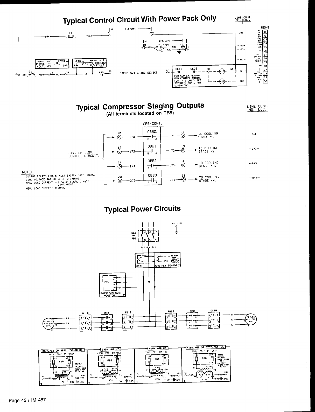
504 ~
Typical Control Circuit With Power Pack Only .,.~,,,.
LINE CONT.
FI
,2
w~
—115/6w1
—1
NB 1
OLIO
+–– OG––+–*–
FOR SUPPIY/RETURN
FIIN CONTROL wIRING
FOR THIS UNIT. SEE
sEPER12TE FWX 1 L !WiY
SCHEMATIC.
I
L_*– J–303-
‘+-’”’-
–2i?–
m-
–
I
Typical
24V. OR 115V.
CONTROL CIRCUIT.
NOTES
OUTPUTRELAYS [ OBB*) HUS1 SNITCH 6C’ LOI$Ds.
LOAD VOL1@3E
)!hx. LO&D CURRENT = 1.80 OT +65-C 114q”F)
H,N. Lor10 CURRENT = 3BIUI.
R12T1NG = 24 TO 140vfiC.
CONT 1 NUOUS .
Compressor Staging Outputs
(All terminals located on TB5)
OBB-CONT.
;:::f~
\:E:+$:::
Typical
OBBO
32
OBB1
Power Circuits
1110
11
171+ —
w,
Gm
TO COOLING
sT14GE ●I.
‘-
–B41–
—842—
—843—
—044—
page 42 I IM
SUPPLY“ 2’
“y, p ,2 2’
cl=
,,
2,
Page 43

Typical Main Control Circuit (VAV Units)
—504 503+---%
ACT I
(SW,
.CAUIICNO
mm, ,0
I
“,CRWKC”
1,., 6LUE1]
mum.!%
- L.X%
A
F1
—!!5/w/l —
WI
,S2 1Slmlw
WCC em. 1
:; 345.
t-))
701 703 705
I
$1
PA
+
[ WTWT
Lm ‘
“d
– 24 VWTS n.C. FRG+I TRAJ&F. (T2) —
702 704 706
,23579
J+kl-11
. .
“O’k!Il - ( WTWT
~. FC+! CCGi
rm s m. M.
“,x,
.7U, ,7W
TO (+, -l m
03c4.
W:%kl
SE 1
–zwe—
—a2–
—2a–
–2m–
–2n —
-m7—
– a7—
-20—
-218–
–,, ,—
–2,2–
–2!, –
-,,4—
-2,5—
—2!G–
–217–
—2,*–
–2,. –
—2,, –
—22, –2,2–
–*23–
–224–
-2,5 —
–226–
–2,7–
I
I
-228–
-,2, –
–23B–
—23, —
–236–
–237—
–25—
–F, —
- z53–a4—
–25–
–z5–
–x7–
- 25–
-z5—
186
-26—
-26—
-264—
- 26S–
-2T, —
-x7—
-268 –
-27a–
-27,—
-27. —
-275—
- 27s—
-277–
-27a–
-,79—
xe—
-ml–
a2–
IM 487 I Page 43
Page 44

r32 508
Typical Main Control Circuit (CAV-ZTC Units) ,Jl,l:%:.
1—!!5 /60/1 —1
“T frf-55’ :: :,..,,,.,.,. 554+1:!?
“,,,. ZU4E
,Ew. S,*OR
‘“’3E
L—
— — &569 5 ;6
— — _&.?z-5,, , J
a
1111111111
m
2n%–
w2-
203-
2e–
x6–
x7–
208-
2n—
.2, n–
-2!l -
-212-
-213–
-2,4—
-2,5–
.,t6—
-2!7–
-2 Le-
.2,.-
-22, -
-222–
-223-
-22*–
-225-
-,26—
-227-
-231-
-232-
,2e—
228–
229–
230–
TB5
I
48
I
543
543
~ -72’P7”-
x. ,;.:~:~,
“*N mr C9W, E0.
, 10 WIA6LE [“lcRUW T1- CLCtK. TE8i4!N4Ls ,01
KITE TO m ,82 !4”S1 NOT 8E -ERED.
FIELQ, 2. IF REMOTE PANEL [S W, uSEO. TEF?!1”AL5 !8>.lffi
m, ,,, ““S1 ,S .41WERE0
1
~6 ,Fm.,,LTER)
,4,L7.3*2,,RN
-?44-?44
,,1’‘ ;.@;~
mm NOT .F?LIEO. .,, .53 $+40 .53 .5. “!s, w Rwwm.
1
II III n
I
NOTE 10 FIELD.
bn~. S“0(, CCTECTCMS oRE F,ELO
SJ,,-L, EO, ,tf <“,, EWEEN lEMINALS
— 24 WITS a.C. FR~ TRANSF. IT21 ~
.——
A
749A+ 010
7’2+L
738
7,.
. .
‘“1
—
—
-236 —
-,37—
-zl -
‘?
-x4–
0
– z,—
-25–
- ?Y—
-z2—
–x3-
–x. -
-x5—
—26—
–x7-
- 2,8—
-270–
—27. -
– 275—
I
-,7&—
–277-
– 27B–
—27,–
—2e@-
—28, —
– 2$2-
N
—zTJ—
Page 44 I IM 487
h
—2,a—
Page 45
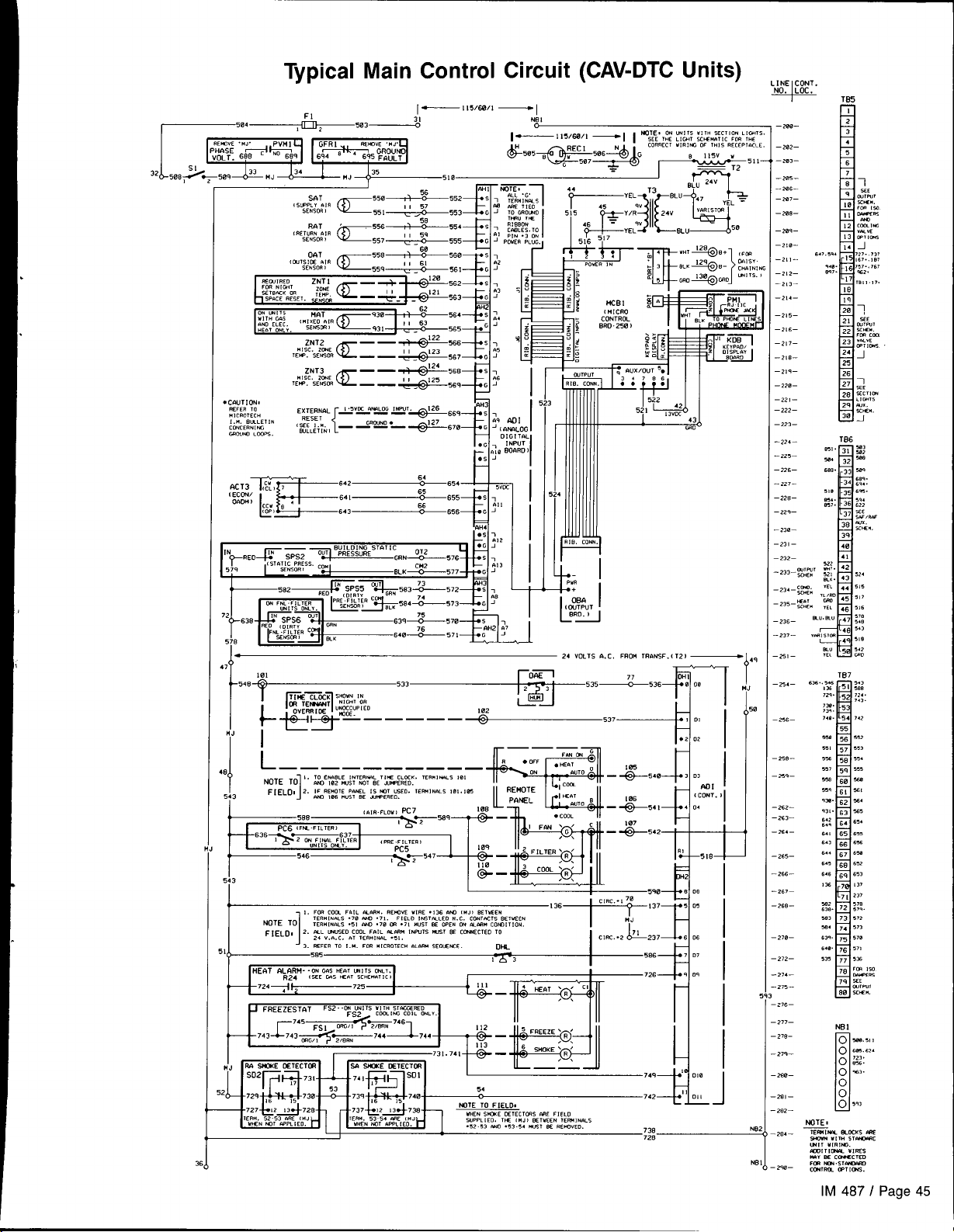
Typical Main Control Circuit (CAV-DTC Units)
.cwTI’w!
mm, m
H, CROTKH
,... sm.,,,. , g:y,
03.,,..,%
Mmm .C0P5
7,
,?
-548
EXTERNAL — — — —
WLLc7,NI — ‘mA”— +#-670
101
{
Y
k$5*-~–––-~537
1
18
5
5
, ma Com FAIL mm”. FmtwE “,,-!, .,W am ,.,, x,”,,”
N07, ml
!1,
P
21
—
7,,.,..,s .7, nNn .71. F,UO ,.srFiLEo ..C. CWTKT, BETKCN
,,,”,..,s .5, M. .7, m .7, .“,, K OK. ON *MC” COB,,,, ON.
[— I1503W1
, wcc mm,,, ,NW,, @26 ,69 ‘: ,
4H
1., . ‘i~Pur-
., ,
i-
,33____+j_535Lz.53+Jq [(
—1
m AD I
G ‘ , mk?,LOG
“,,,, ,., ,
.,0 BOARD I
.
H=
... .“.
BRD .250 )
w+--!
,;,
+
x
T
( C%$UT
L
“l
1
– 24 VOLTS A.C. FROM TR’wJSF. ( 12)
‘3’*’37f10’ i
—1.4
!0,
‘- ,..
—20–
– x2–
—m, —
–x5–
-2aG—
–x7–
–2’a–
–2a–
—2!a–
-2, ,-
–2,2—
–>,3—
–2,4—
–,,5–
–,,6—
–2,7–
–,,8—
–2,9—
–22a–
–221–
–222–
–223–
-224—
- ,,5—
- >26—
-227–
-228–
- 229—
-238 –
-231–
232—
z,,—
-2,7—
-2$–
-z4—
256–
-xe–
25—
-26—
-x,—
-26–
,65—
,,, —
2,7—
.26—
278–
272–
.27. —
275—
z,6–
277–
278-
27,—
2se—
2a—
282—
36
N
IM 487 I Page 45
Page 46
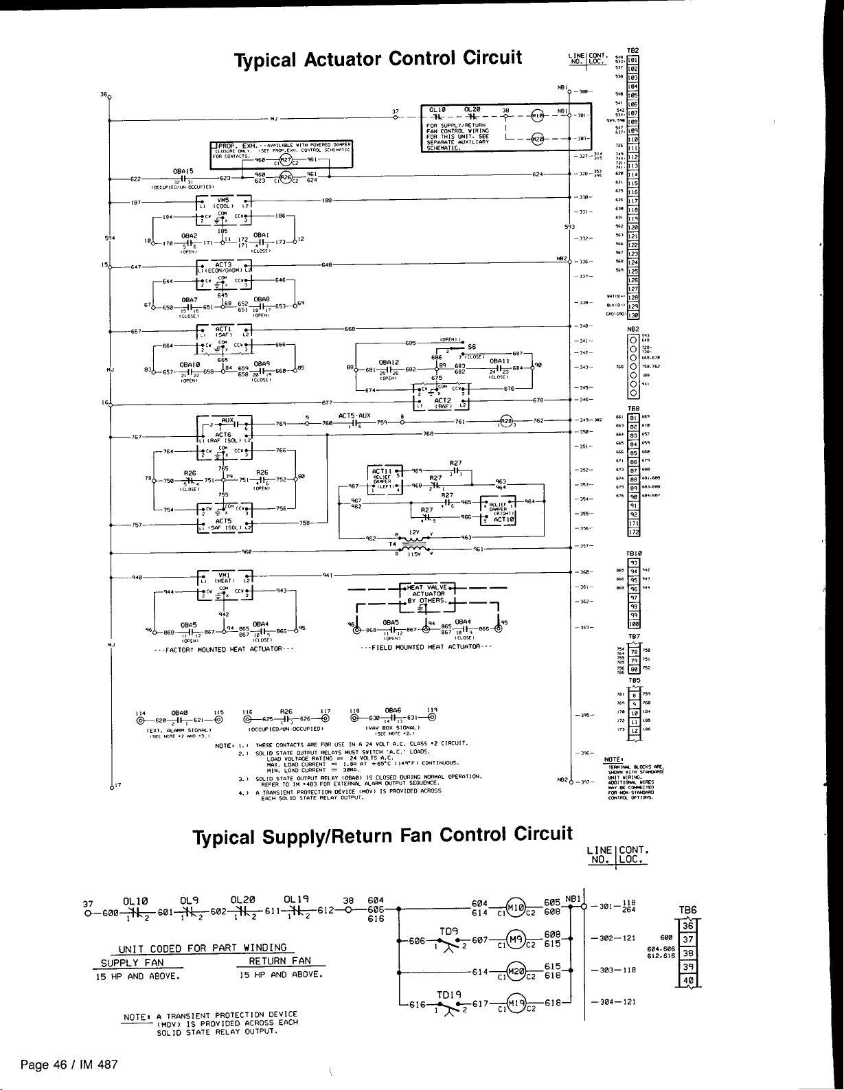
Typical Actuator Control Circuit
PROP. EXH. -. ,val,ac W(1H ,ow=e,O Da”pEa
‘E& ‘-e
‘a7~-~ ‘“
r
5,4 ,a
15
L
“~’ ii-Ai ’78—
+------ ~ “-‘“=” ‘“
~“zy~].“’~::j?g:i
“,
“4-E”m&-’86
,,,’5:,,,&1729’
I
, :.,.’,
“7--IZ-0.Z(CL”F’ ‘“’
,7, , *[73 12
1
r7’4+l”@2+76’l
,0.,. ,
-FoCTORY MOUNTED HEAT 6CTUATOR - -.
{cm<, )
,0.,.,
-- .FIELO MOUNTED HE8T 4CTUaT0R -
, ,,05! ,
-,m–
-33, –
5
-322–
)62
-,3, –
–,37–
- ,M–
- 34a–
-,4)–
- >42–
-,4,–
- ,4,—
- ,4,–
- 3.9– m2
-3%–
- ,5t –
352 –
–
–3,, –
– 35. –
– ,55 –
–,%–
– ,57–
–,m–
–3,)-
– 3.5, –
– ,,3–
SUPPLY FAN
15 HP AND ABOVE.
Page 46 I IM 487
NOTE, 1. ) TI+ESS CONTACTS AFIE FOR USE [N . 24 VOLT 6.C. CLASS ‘2 CIRCUIT.
2. ) SOLID STaTE OUTPIIT !+=1 r3YS ..S1 SWITCH ,0. C. LOADS.
3. B SOL 10 57’2TE OUTPI
.,,.. ,. ,“ .4,
,7
I
. .
\ a ,..,,.! .;,” ..”,,,,10. DEVICE ( !40” ) IS PROVIDED ‘ACROSS
4.) . .
Ec,c” yx ,0 Si. fi ii.” OUTPUT.
Supply/Return Fan Control
UNIT COOED FOR PART WINDING
NOTE I s TRANSIENT I’RoTEcTloN oEv IcE
— (!40v) IS PROVIOEO aCROSS EACH
SOL]O sTRTE RELAY OUTpUT.
RETURN FAN
15 HP ANO ABOVE.
LOAD VOL lMX
.,x, Lam CUR
“[N, L06D CUR
;.T !-Nt = 24 vOLTS 9. C.
RRENT = 1.80 S3T +65. C ( 14,-F I CONTINUOUS.
RRENT = 38.,,
,“T ~LhY ( 06681 IS CLOSCO DURING NORM*L 0PER6T ION.
133 FOR ExKmm .LnR. cmpur 5EOUEKE.
~ZZg’O]
C2 615
cl
M20
C2 618
cl
~lM19c2 618
615
–,*–
—302—121
—303—118
—304—121
TB6
600 37
604.606
612.S16 38
1
36
39
40
Page 47
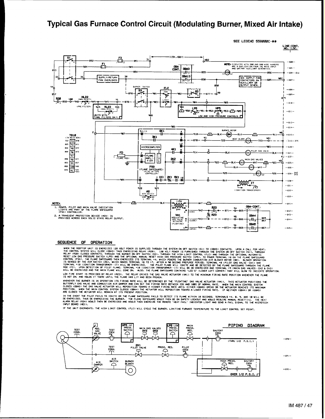
Typical Gas Furnace Control Circuit (Modulating Burner, Mixed Air Intake)
NoTEl
!. POWER. PILOT IWO M61N VhLVE lNOICATl ON
L 1 GHIS ORE PN?T W Thf FLCi!!E SAWW4SD
1FSG I CONIRGLLER,
2. A lRfiNS!ENT FROTEC11C+4 DEvICE IMOV] 1S
PROVI DEO ,USOSS EACH 30L ID STATE RELAY OUTPUT.
940 /iEJ
A
A,, ,“,,,,
L-#
co” m
!?
I
.~
+?
As
&K—
I
(
,m, , ,CN TPms;mim,
SEQUENCE OF OPERATION
W+EN WE RC93F1W WIT 1s ENERolzfO 120 Vul POWER 1s SWPLIEO THRWJ3H lK$ SYSTEM ~.WF WITCH (s1 3 TO toEn31 CCUIKTS. wmi R cm_L FOR HEAT,
TIE CONTROL SYSTEM WILL CLOSE [0Bf131 TWS E% RGIZING REL#i (RZB).
MLfiV (R28) CLOSED CWIACTS. TW(OuW TuE W?WR W. OFF SWITCH (S31. lFMOffiH TliE HIW LIMIT CCUTRfJL lFLC) MICl THSWW THE WT1ON& WTOM& TIC
RESET LO” C4S PRESSM S“[ lCH 1LP51 W T= WT1~ H#S(lW SE3ET HIGi GAS PRESSURE SV! lCH [ l+%,, TO POWER TERM!wL .6 ON THE FLti 3PfEGUAWl
Ccwlful. lFSGI. THE FLhNE s.wEGwAll THEN EWRGIZES 11s TERMIwL .4, WHICH POWERS 1S 2wNER CC4!+WSTION IIIR BJWER MOTCFI (w,. EIOUER CPEIWTU2N
Is SEs5m W THE nlR WITCH cASI. WHICH #AKES TERMINAL .6 TO .7. hFTER & % WC~ PREP”RGE PER1OO. lESMI)klL .E (PILOT WS V61LVE. .GVI ) A&U
TEWINAL .10 (IONIT]W TRwSFCZ=WER-.111 WILL 2E EMFRGIZEO.
RCO IFD1. UPON ~TEc1!G+4 W PILOT FL%. TER!41?4,% .18 ttGN1ll ON TRANSFC#lMCR. .IT1 WILL BE 13 E. EMERGIZEO f#4Q lER”l NAL .q (FAIN GhS VALVES.. GV2 & Gv3>
MILL 3t ENERc12E0 nuo Tw MIN FLW WILL co% w
LOU FIRE START 1S PSWIOEO W REL.IY 1R23). THE REL12Y ORIVES THE GsW VALV2 6CT14?T~ (WI 1 TO T* ❑ INIMUM FIRlffi RATE FUSIT!CN MHENSVER THE FL#VE
[S NOT ON. M ~D5 IT TwERE UNIIL lHE FLA)lE HIW LIT 6$93 BEEN PSOVEN.
U~NEVER THE w$WR IS IN OPERATION ITS F! R1ffi RATE U(LL BE CE1EG141WD W THE .FLOfiTl M7. GAS V#LVE hCTUnTCSi (W! 1.
uullEsfLy cns VfiLVE w Cw5710N AIR WIPER nm cnN SET T= FIRING MIE i7E7wEN 33% M wiw w NC+IMOL RaTE. ww 7~ n,a IN CONTROL SYSTEM
CLrlSES (CW5) W+ GfiS V,%VE ACTLkaTOR WILL REPOSITION TOW,SD a HI(WER FIRlffi WTE lMTIL EITHER (~h5) OPENS LM THE AC1U9TOR RERCHES 11S WXIW+!
Pffil TlC?4. W2N THE IWIN CCNTR~ SYSTEM CLOSES (C%A4) WE MTu.4T~ “ILL REPOSITION 10W,RD t! LOVER FIRING RIITE. 16 WI TtilR (LMh4) OR ,0 Bfi5)
4SE CL03E0 TtBZ ACTUATOR MILL REIMIN 6? ITS ME3ENT POS!T! ON.
IN T* EvEN7 TM PILOT FAILS To !GNITE m T* FL* sh=cGunRo FarLS TO OETECT !7s FLfis WITHIN Ia SECMS, TERHIMLS .4. 0. q. ~ ,0 “,LL ~
N. ENERGIZEO. 1w2 %. EWRGI ZING 1* 8WR. THE FLRW SAFEW~ MW-O lWN SE W S,WETY LOC103LlT A)4D MW10 REWIRE M6Wm RESETT 1,,G, TW W*T
nLA7H sww tR248 mu-o T*N x ENER012E0 ern wcuo T*N E* SGIZE T* REW3TE .*fiT FAIL. lPiOt cATOR LIGHT aso SEW n Fnt L SIGWL TO T* Ml CR07ECH
[M=(JT SLwin cm]).
IF 1H2 WIT OVER~&TS. THE H!DH LIMIT CWIROL (FLC1 WILL CYCLE Thl 8L!WEFI, LIMIT Iffi F12wACE TE”mw,”RE TO TW L,”, T cWTRW SET PO, NT.
WSO. WE FL~ SWEWa~ CUiThlffi .LEO.5. (LOWER LEFT CL!+7NER, TMT WILL WOW 10 !NDICATE CWRfiTICti
130 VOLT POUER IS FLWN1514E0 1HRCW3H THE SYSTEM C+-WF SWITCH (S11. 1-
Tw p] LOT FLIWS UlLL IWITE mm ~ 027 ECTE0 w 1* FL.wE 3wEwm wwur,n THE FLWt
lHIS ACT~TOR PoSITIONS THE
I -613–
I -,,4-
—6,, – 6.,2—
–63, –
-63, –
–,3?–
-,,3-
I
—6.2—
–643–
—644-
-645–
-6,5-
–,,6–.975
TEST
W] lCH M_Si?4ER
ys~~
SWITCH REG. WTDFF
~ESS. SEG.
LOv
W
MAIN
PsEss.
a,
P!L0T
COCK
& i
PIPING DIAGRAM
CEK
+1
-a~
“~
—8,,–
HIGH PRESS.
I
~lH@
I
OkER
S;U&l ;
-s,2–
1/2 P,S. I. r
IM487147
Page 48

Typical Electric Heat Control Circuit (Multi-Stage)
ELEC. C
FB32
M32
(M. I
w
FB41
FB42
LI
L2
L3
FB43
FB44
M41
)442
M43
H44
(w. !
,*N I
(w. !
,*, I
BOTIOH BANK ‘ B“
,2
TICI
,2
m
,2
w
-t.,,-
-012-
-813-
-,,4—
Lb
-stc.-
1.>
-81c-
-,,,-
-818—
-s,!-
- 82@-
LI
-62!-
L]
-522-
- Bzl-
-824-
- sm-
- 82a—
- 5z7-
-021-
- s29-
- s3a-
-81t —
- 8Y2-
Ll
- .331—
,1
- n34-
Page 48 I IM 487
0BA4
m353&e6& _
007 ,, 7
oBA5
8’673&8& — 911 , ~
809 !2 ,1
08A6
*.,.4
17
e8?~l#W~ — 916 ,- -2
q5 ~a6
E
qs
E
97
E
(w,, r
HL32
12
936
,Wlol
HL33
941
IWO,
HL34
5 :/
=?46
,ml,.)
t4L42
tz
,Nnol
HL43
,2
(Ml, !
HL44
12
“18 “2”:, 32 C2 :: –864- 818
%!7
*TR‘2”;, 42 ~2 ;:;
q37
“ln “3<’;, 33~z 913 -WI-
912
n“ “’”:, 43 ~z q43 -B72- 524
942
“n ““e;, 34 ~2 q18 -574- ~~9
q17
“m “’”;, 44,2 940 -s,,- 339
q47
-566— 51a
UZ4
903
q48
Page 49

Unit Options
Enthalpy
Outside Air Enthalpy Control (OAE)
Units with an economizer come standard with an electromechanical enthalpy control device (OAE)
the humidity and temperature of the outside air entering the
unit. This device has an enthalpy scale marked A through D,
Table 10 shows the control points at 50% .RH for settings A
through D, Figure 35 shows this scale on a psychometric
chart. When the outside air conditions exceed the setting of
the device, the outside air dampers are positioned to the mini-
mum outside air intake position by the MicroTech controller.
Table 10. Errthalpy Control Settings
Control Point 0F ( oC) at 50% RH
~
Differential Enthalpy Control (OAEIRAE)
An optional electronic differential enthalpy control arrange-
ment (OAE/RAE) is available. In this configuration a solid-state
humidity and temperature sensing device is located in both
the return (RAE) and outside intake (OAE) airstreams. This
OAE device has the same A through D scale as the device
described above. However, with the OAEIRAE arrangement
the switch on OAE must be set all the way past the “D” set-
ting. With this done, the MicroTech controller will adjust the
return and outside air dampers to use the airstream with the
lowest enthalpy.
which senses both
Control
Figure 35. Enthalpy Control Settings
Part Winding Start
The part winding” start option is used to reduce the locked
rotor inrush current of the fan motors (208/230 volt units).
The motor has dual windings which are energized with dual
contractors. The first contactor closes, energizing one winding.
A time delay relay closes the second contactor about one se-
cond later, energizing the second winding and bringing the
motor
up to full speed. Figure 36 is a typical wiring schematic
showing part winding start.
Figure 36. Part Winding Start
TD9
.—
rI
I
L
.—
4)
Motor Contractors
1
J
Ground Fault Protection
The ground fault protection is designed to protect motors from
destructive arcing ground faults. The system consists of a
ground fault relay and a ground fault current sensor. The
ground fault relay employs solid state circuits that will instanteously trip and open a set of relay contacts in the 115
volt control circuit to shut the unit down whenever a ground
fault condition exists, The ground fault relay is self powered,
The ground fault sensor is a current transformer type of device
Iocated at the load side of the power block through which the
power wires of all phases are run.
Phase Voltage Monitor
The phase voltage monitor protects against phase loss (single
phasing) when any one of three line voltages drop to 74% voltage monitor is located on the load side of the power block
or less of setting. This device also protects against phase
reversal when improper phase sequence is applied to equipment, and low voltage (brownout) when all three line voltages
drop to 90%0 or less of setting. An indicator run light is “on”
when all phase voltages are within specified limits. The phase
with a set of contacts wired to the 115 volt control circuit to
shut the unit down whenever the phase voltages are outside
the specified limits.
IM 487 I Page 49
Page 50

Optional Remote Monitoring and Control Panel
One to eight applied rooftop units can be incorporated into Figure 37. Remote Monitoring and Control Panel
a network with” the MicroTech Remote Monitoring and Con-
trol (RMC) Panel. The optional RMC Panel provides the following keypad programmable features:
. Remote unit monitoring (up to eight)
. Common duct static pressure and heat/cool changeover
control of multiple VAV units (groups of two to eight)
. Common zone temperature control of multiple CAV units
(groups of two to eight)
● Optimal start control of each unit
. Common unit scheduling
For further information refer to Bulletin No. IM 444, “MicroTech
Remote Monitoring and Control Panel.”
Micmlecil
!ap@ed Fu3dtoP
Remote Monitor Panel
The optional Remote Monitor Panel provides remote indicator
lights and fan on-off and system heat-auto-cool switches. Refer
to Figure 38.
Wiring should be sized in accordance with Table 11 and
connected to the panel terminals in accordance with the unit
wiring diagram. The panel can be mounted on a standard 4x4
junction box.
If the Remote Monitor Panel is not used, terminals 101 and
105 must be jumpered to enable cooling, and terminals 101
and 106 must be jumpered to enable heating. The fan is enabled when either cooling or heating is enabled.
Table 11. Low Voltage Field Wiring
~
“Maximum wire length is based on a voltage drop of 2 volts
External
An external time clock can be used as an alternative to (or
in addition to) the MicroTech controller’s internal scheduling
function. The external timing mechanism is set up to open
and close the circuit between field terminals 101 and 102.
When the circuit is open, power is not supplied to digital input DI (terminal DHI-1) on the ADI board. This is the normal
condition in which the programmable internal schedule is
Figure 38. Optional Remote Monitor Panel
HEAT
AUTO
;Ooi
ON
OFF
R
B
•1
I
•1
•1
I
•1
L
I
I
Time Clock
followed, When the circuit is closed, power is fed to DH1-1.
The MicroTech controller responds by placing the unit in the
occupied mode, overriding any set internal schedule.
For more information, see the “Digital Inputs” section of
Bulletin No. IM 483, “MicroTech Applied Rooftop Unit Con-
troller.”
Smoke
Optional smoke detectors can be located at the supply and
return openings. The wiring schematic for these smoke detec-
tors is shown on any of the “Typical Main Control Circuit”
schematics in the “Wiring Diagrams” section of this manual.
The sequence of operation for these detectors is as follows:
When smoke is detected by either sensor, the normally closed
sensor contacts open. This removes power from digital input
Dll (terminal DH2-11) on the ADI board. The MicroTech controller responds by shutting the unit down. The controller
Freeze Protection
An optional freezestat is available on any unit that has hot
water or steam heating coils. The sensing element is located
on the downstream side of the heating coil in the heating section of the unit, If the freezestat detects a freezing condition
Page 50 I IM 487
Detectors
is placed in the Alarm Off state, and cannot be restarted until
the alarm is manually cleared. Refer to the operation manual
supplied with the unit for information on clearing alarms (see
Table 1).
The smoke detectors themselves must be manually reset
once they have tripped. A reset button is provided on the front
face of the smoke detector (refer to Figure 6 for smoke detector
locations).
and closes, the MicroTech controller will take different action,
depending on whether the fans are on or off. The freezestat isan
auto reset type of control; however, the controller alarm it causes
is manual reset if the fan is on and auto reset if the fan is off.
Page 51

Fan On Operation
Fan Off Operation
If the freezestat detects a freezing condition while the fan is
on, the MicroTech controller will shutdown the fans, close the
outdoor air dampers, open the heating valve and cooling cooling valve, and set a 10-minute timer. The MicroTech
valve, and set a 10-minute timer. The MicroTech controller’s
current alarm (menu 29) will be “Freeze Stat Fail.”
When the 10-minute timer expires, the controller begins
checking the freezestat again. If the freezestat is open, the heating and cooling valves will close. If the freezestat closes
heating and cooling valves will close. If the freezestat closes
again, the heating and cooling valves will open, and the 10minute timer will reset.
The unit will remain shut down until the “Freeze Stat Fail”
alarm is manually cleared. Refer to the operation manual sup- allows the system to start normally after a cold night.
plied with the unit for information on clearing alarms (see Table 1).
If the freezestat detects a freezing condition while the fan is
off, the MicroTech controller will open the heating valve and
controller’s current alarm (menu 29) will be “Freeze Stat Prob.”
When the 10-minute timer expires, the controller begins
checking the freezestat again. If the freezestat is open, the
again, the heating and cooling valves will open, and the 10minute timer will reset.
When the freezestat opens again, the “Freeze Stat Prob
alarm automatically clears. This feature protects the coil and
Duct High Pressure Limit
The duct high pressure limit control (DHL) is provided on all
VAV units, including the CAV-DTC unit that can be field converted to VAV. The DHL protects the ductwork, the terminal
boxes, and the unit from overpressurization which could be
caused by, for example, tripped fire dampers or control failure,
The DHL control is factory set to open when the discharge
plenum pressure rises to 3,5” WC, (872 Pa), This setting The alarm must be manually cleared before the unit can start
should be correct for most applications; however, it is adjustable. Removing the front cover of the device reveals a for more information on clearing alarms (see Table 1).
scale showing the current setting. Turning the adjustment
screw located on the bottom of the device adjusts the setting
up or down.
If the DHL switch opens, digital input D7 (terminal DH1-7)
on the ADI board will be de-energized. The MicroTech controller then shuts down the unit and enters the Off-Alarm state,
again, Refer to the operation manual supplied with your unit
Variable Inlet Vanes
Variable inlet vanes are installed on the supply and return fans
of VAV units. They are also installed on the return fans of constant volume units that have direct building static pressure
control capability.
The inlet vane assemblies consist of airfoil type inlet funnels
with integral sets of lever-actuated radial vanes. DWDI housed
supply fans have one assembly on each side of the fan. Return fans, as well as units with SWSI plenum supply fans, have
one assembly on the inlet side of the fan only, When they
open, the inlet vanes direct air in the direction of wheel
rotation.
The vanes are able to rotate 90° from full closed to full open.
A stop limits the amount of travel open and must not be
changed. Driving the vanes past this stop will cause the vane
hub cam linkage to disengage. The vanes will turn independently of each other, and the hub assembly will have to be overhauled. The moving parts of the vanes are permanently lubricated. All threaded fasteners must be periodically checked
for tightness.
All airfoil fans with inlet vanes are provided without motor
actuators for field control installation, or maybe shipped from
the factory with complete linkage and actuator assemblies.
Field installed linkages and actuators would be connected at
Point B on Figures 39, 40, and 41,
Minimum Vane Position
Operation with the inlet vanes closed completely may result
in fan pulsation and excessive vibration. In units equipped
with MicroTech controls, the vanes are automatically opened
approximately 5 degrees by the control system prior to fan
start-up. Field installed linkages and actuators should be
preset to close to no less than 5 degrees open.
DWDI Housed Supply Fan Vane Adjustment
Figure 39 shows the supply fan vane linkage assembly. Both
sets of vanes on the supply fan must operate in unison, Ad-
justments to the motor rod end and locknut (Point A) as well
as to the floating link ends (Point C) can be made to assure
uniformity between the linkage assemblies.
The vane actuators must have 180-degree rotation. Do not
make linkage adjustments to compensate for improper actuator rotation, but correct the actuator rotation adjustment.
Refer to “Actuator Rotation Adjustment” on page 55.
There are two difference actuator rotation configurations.
These are shown as View 1 and View 2 in Figure 39. Refer
to Table 12 below to determine which view applies to a particular unit,
On units with vane controls on both the supply and return
fan, it is important that both actuators have exactly 180-degree
rotation to assure proper “tracking” of the two actuators.
Table 12. Applicable Actuator Linkage Configurations
Supply Fan “z”
Wheel Size
in Inches (mm) Figure 39)
27
30 42.3 (1074 mm)
33
36
36 51.5 (1308 mm) 50—60 1
40 56.8 (1443 mm) 15—40 2
40 58.8 (1443 mm)
(Refer to Reference
38.1 (988mm) 5—40 2
464 (l179mm)
51.5 (1308 mm)
Motor
HP
5–40 2
5—40 2
5—40 2
50–75 1
Note:
Figure 39
View
Inlet vanes must not be adjusted to close tight during fan
operation.
I
A minimum operating position of 5 degrees open is recoin.
mended to avoid pulsation,
I
Unitswith factory installed MicroTech controls will automatically
open vanes 5 degrees prior to start-up.
IM 487 I Page 51
Page 52

39. DWDI Housed Supply Fan Vane Assembly
Figure
VIEW#l, -’-—--\,
/’
/“
OPEN
ml-l
\
.
\
d I-HI-i
“B”
#
/
(BOTH SIDES)
-.
\
‘\
ADJUSTABLE
(Iv,’
*
[za~m] SLOTJ
‘\
-~aczos
/- —----
,/ ‘FLOATING
/
/
“:\
\
\
I
I
I
i
~k ---
--,
‘\
VIFW #2 /’
\
/
.-
/-” —--,
\
‘\
‘\
.
—--
-/’
/
/
/’
\~ CLOSE~/ ‘
\
-------
/
Y&?%,,
Plug Supply Fan Vane Adjustment
Refer to Figure 40a for 40” wheels, Figure 40b for 44” wheels,
and Figure 40c for 49” wheels. The vane actuator must have
180-degree rotation. Do not make vane adjustments to compensate for improper rotation, but correct the actuator rotation adjustment. (Refer to “Actuator Rotation Adjustment” on
page 55.)
Figure 40a. Supply Fan Assembly (40” Wheels)
i
/
i~
/’
1’
18”
-=-—.
,/”
/’
/’
. .
\
. .
\
As the actuator moves from Odegrees to 180 degrees, the
vanes should move from O degrees (closed) to 90 degrees
(full open). This can be adjusted by changing the linkage rod
Iength by loosening the nut and sliding the rod at Point A or
Point B and retightening the nut.
-“/
Page 52 I IM 487
‘\
‘/
A
r-
“.
\
‘.
\
-. ,.
=..
—— --
1
/’
/’
/’
/
Page 53

Figure 40b. Supply Fan Assembly (44” Wheels)
“’Q-=14’7
--- ../
./ ---- -.
.,. . .
./’
/’
““ CL
/’
/’
/
i
i
\
A
-~\. ,-
Cw
PEN
m)
~..
‘\
“\
‘.
\
‘,
\
\
/’
\
i
I
i
Figure 40c. Supply Fan Assembly (49” Wheels)
.. ——-..
-—----
[ 180” CW i
/’
/’
,/’
,<
---
‘,
\ TO OPEN ‘
‘. i
\
‘.
\
..
‘ +,
\
OPEN
..
\
. .
. .
\\\\\\
‘\
~.
\
..
\
..
=..
. .
. .
---— .. _.. _ ----
IN
7//
OPEN
w
/“
,.-
./--
/’
/’
,,
/
“\\ , ‘ ‘
‘\\ /“
i,;
I
I
‘1
..
,.
OPEN ,/’
-— ---
‘.
\
\
\
i
m) i
I
/’
.,
10 To 40 HP
50 To 75 HP
IM 487 I Page 53
Page 54

Return Fan Vane Adjustment
Refer to Figure 41a for 40” wheels; Figure 41b for 44” wheels.
The vane actuator must have 180-degree rotation. Do not
make linkage adjustments to compensate for improper rotation, but correct the actuator rotation adjustment. (Refer to
“Actuator Rotation Adjustment” on page 55.)
Figure 41a. Return Fan Vane Assembly (40” Wheel)
/
/’
y
A
[
[ ‘- ‘-
CLOSED
i
‘\
‘\
‘m-
“\
‘-.-
2,30”
(58mm)
--. —.-.
As the actuator crankarm rotates from O degrees to 180
degrees, the vanes should move from O degree (closed) to
90 degrees (full open). This can be adjusted by changing the
linkage rod length by loosening the nut and sliding the rod
at Point A or Point B and retightening the nut.
VIEW A-A
\
i
1
.-
0-
OPEN ,/’
./”
‘1
/
/’
0’
—.—-——-
/“
Figure 41b. Return Fan Vane Assembly (44” Wheel)
.Z ------ --.<.
/
/.
.0.
/
i
i
i
i i
“\
.\
.\
.\.
d >% 1’
\
“<.
---. s
-.%
-------- .
.\
‘\
.\
.\.
\B
.\
----- -.
.\.
\-
\.
\.
\
.\
‘\
;
;
/.’
0.
#.
-.
.-
./
./
! \
1“ .\
~18”
i
i
“\ 1“
.x.
-------
180” Cw
TO OPEN
[
\
.\
2.65” (67m’m)
“\
i
i
Page 54 I IM 487
Page 55
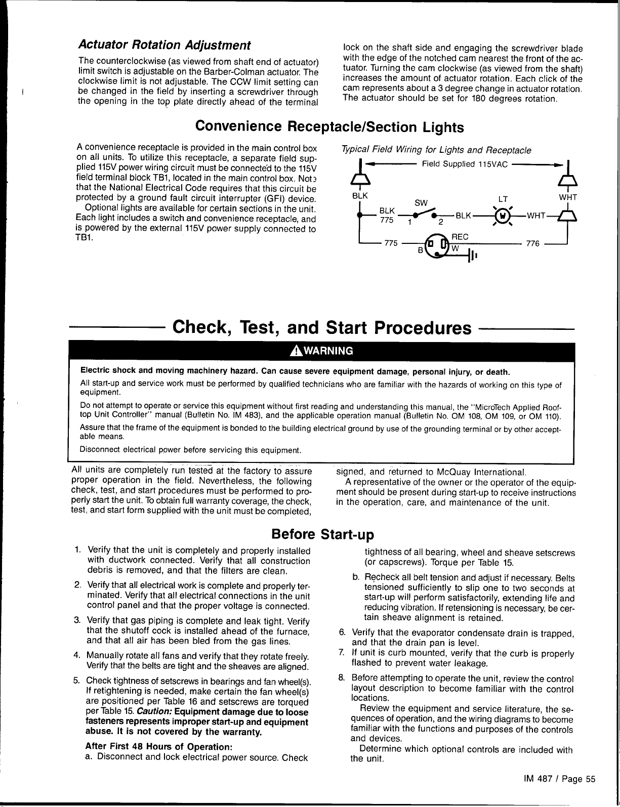
Actuator Rotation Adjustment
The counterclockwise (as viewed from shaft end of actuator)
Iimit switch is adjustable on the Barber-Colman actuator. The
clockwise limit is not adjustable. The CCW limit setting can
be changed in the field by inserting a screwdriver through
the opening in the top plate directly ahead of the terminal
Convenience Receptacle/Section Lights
lock on the shaft side and engaging the screwdriver blade
with the edge of the notched cam nearest the front of the ac-
tuator. Turning the cam clockwise (as viewed from the shaft)
increases the amount of actuator rotation. Each click of the
cam represents about a 3 degree change in actuator rotation,
The actuator should be set for 180 degrees rotation.
A convenience receptacle is provided in the main control box
on all units. To utilize this receptacle, a separate field supplied 115V power wiring circuit must be connected to the 115V
Typical Field Wiring for Lights and Receptacle
~
Field Supplied 115VAC ~
field terminal block TB1, located in the main control box. Note
that the National Electrical Code requires that this circuit be
protected by a ground fault circuit interrupter (GFI) device.
Optional lights are available for certain sections in the unit.
Each light includes a switch and convenience receptacle, and
is powered by the external 115V power supply connected to
&
BLK
+-
>~BLK~WHT
BLK
775 +
LT
9
. .
TBI. -
‘775+77’A
Check, Test, and Start Procedures
Electric shock and moving machinery hazard. Can cause severe equipment damage, personal injury, or death.
All start-up and service work must be performed by qualified technicians who are familiar with the hazards of working on this type of
equipment.
Do not attempt to operate or service this equipment without first reading and understanding this manual, the “MicroTech Applied Roof-
top Unit Controller” manual (Bulletin No. IM 483), and the applicable operation manual (Bulletin No. OM 108, OM 109, or OM 110).
Assure that the frame of the equipment is bonded to the building electrical ground by use of the grounding terminal or by other accept-
able means,
Disconnect electrical power before servicing this equipment.
4
WHT
4
All units are completely run tested at the factory to assure
proper operation in the field. Nevertheless, the following
check, test, and start procedures must be performed to pro-
perly start the unit. Toobtain full warranty coverage, the check,
test, and start form supplied with the unit must be completed,
Before
Verify that the unit is completely and properly installed
1.
with ductwork connected. Verify that all construction
debris is removed, and that the filters are clean.
Verify that all electrical
2.
minated. Verify that all electrical connections
control panel and that the proper voltage is connected.
Verify that gas piping is complete and leak tight. Verify
3.
that the shutoff cock is installed ahead of the furnace,
and that all air has been bled from the gas lines.
4.
Manually rotate all fans and verify that they rotate freely.
Verify that the belts are tight and the sheaves are aligned.
Check tightness of setscrews in bearings and fan wheel(s).
5.
If retightening is needed, make certain the fan wheel(s)
are positioned per Table 16 and setscrews are torqued
per Table 15. Caution: Equipment damage due to loose
fasteners represents improper start-up and equipment
abuse. It is not covered by the warranty.
After First 48 Hours of Operation:
a. Disconnect and lock electrical power source. Check
work is complete and properly ter-
in the unit
signed, and returned to McQuay International,
A representative of the owner or the operator of the equipment should be present during start-up to receive instructions
in the operation, care, and maintenance of the unit.
Start-up
tightness of all bearing, wheel and sheave setscrews
(or capscrews). Torque per Table 15.
b. Recheck all belt tension and adjust if necessary. Belts
tensioned sufficiently to slip one to two seconds at
start-up will perform satisfactorily, extending life and
reducing vibration. If retensioning is necessary, be cer-
tain sheave alignment is retained.
6.
Verify that the evaporator condensate drain is trapped,
and that the drain pan is level.
7.
If unit is curb mounted, verify that the curb is properly
flashed to prevent water leakage.
Before attempting to operate the unit, review the control
8.
layout description to become familiar with the control
locations.
Review the equipment and service literature, the se-
quences of operation, and the wiring diagrams to become
familiar with the functions and purposes of the controls
and devices.
Determine which optional controls are included with
the unit.
IM 487 I Page 55
Page 56

9. Before closing the power disconnect switch, open the
following unit control circuit switches:
a. Main Control Panel
● Turn system switch S1 to “Off.”
c Electric heat units: Turn switch HS1 to “Off.”
b. Furnace Control Compartment
● Turn furnace switch S3 to “Off.”
10. If the VAVor CAV-DTC unit does not have an optional zone
Power-up
temperature sensor (ZNT1) connected to it, change the
entry under keypad menu item 28 (“Space Sensor=”)
from “Yes” to “No.”
If desired, all MicroTech internal control timers can be
11.
reduced to 20 seconds by changing the entry under
keypad menu item 28 (“Timers=”) from ‘(Normal” to
“Fast.” This will reduce the delays associated with normal control action for 15 minutes or until the entry is
changed back to “Normal.”
1. Close the unit disconnect switches.
2. Turn the S1 switch to “On. ” Power should now be supplied
Fan Start-up
1. If the unit is equipped with an optional Remote Monitor
Panel, turn the on-off switch to ‘rOn," and turn the heat-
auto-cool switch to “Auto.”
2. If the RAH has controls, place the unit into the “Occ-Fan
Only” mode through keypad menu 11 (“Control Mode”). If
the RAH has no controls, check the fan rotation and continue on to Step 3. The controller should enter the Start-
up Initial operating state. After the Startup Initial timer
has expired (3 to 4 minutes), the fans should start. Observe the fan rotation and, if it is backwards, disconnect
power and reverse two legs of the power supply.
If a fan does not run, do the following:
a. Check the control circuit fuse (Fl).
b. Verify that the overloads have not tripped.
c. Check the fan motor power fuses.
d. Verify that the Remote”Monitor Panel wiring is correct
(if any).
Economizer Start-up
to the MicroTech controller, and the LED’s on MCBI (red,
green, and amber) should follow the normal start-up sequence (refer to the “Component Data” section of IM 483).
e. Trace the circuits.
3. If the fans are equipped with optional spring isolators,
check the fan spring mount adjustment. When the fans
are running they should be level. Refer to “Spring Isolated
Fans” in the “Preparing Unit for Operation” section of
this manual for information,
Note: The supply and return fan drives are usually selected
for operation in the drive’s midspeed range. The return fan
drives are usually shipped with fixed pitch sheaves that will
provide the selected fan speed; however, the supply fan drives
are usually shipped with variable pitch sheaves that are ad
justed to provide the minimum fan speed. Both drives should
be adjusted for proper airflow during air balancing. For more
information, refer to “Air Balancing” near the end of this
section.
Improper adjustment may damage the dampers.
Assure proper damper adjustment. When an economizer is
ordered without an actuator, the linkage requires a 3.14-inch
(80mm) linear stroke to fully open it. Do not allow dampers
to be driven beyond their normal full closed or full open
positions.
Check whether the outdoor air is suitable for free cool-
1,
ing by displaying keypad menu 9. “Low” indicates low
outdoor air enthalpy; “High” indicates high outdoor air
enthalpy.
Referring to “Enthalpy Control” in the “Unit Options”
section of this manual, verify that the enthalpy changeover control is working properly. You may want to take
temperature and humidity measurements.
2. At the keypad, set the cooling setpoints low enough so
that the controller will call for cooling. On CAV-ZTC units,
adjust the “Cooling Spt =” entry on menu item 12. On
VAV or CAV-DTC units, adjust the “Cooling Spt =” entry
on menu item 12 and the Setpoint=” entry on menu
item 13.
Page 56 I IM 487
Place the unit into the “OCC-COOIOnly” mode through
3.
keypad menu 11 (“Control Mode”).
4.
Observe the outdoor air dampers.
If the outdoor air enthalpy is low, the Step-and-Wait
algorithm should modulate the dampers open.
If the outdoor air enthalpy is high, the dampers should
maintain their minimum position. Set the “Min Airflow=”
entry on menu item 21 to some other value. Verify that
the dampers move toward the new minimum position
setpoint.
If the unit isequipped with the electromechanical en-
5.
- r
thalpy changeover control (Honeywell H205) and the outdoor air is borderline, attempt to change its input to the
MicroTech controller by turning the switch to “A” or “D”.
Check menu 9. If the changeover occurred, go to step
4 above.
Note: It may not be possible to check the economizer
operation in both low and high enthalpy states on the same
day. If this is the case, repeat this procedure on another day
when the opposite outdoor air enthalpy conditions exist.
Page 57

Heating System Start-up
General
1.
At the keypad, set the heating setpoints high enough so
that the controller will call for heating. On CAV-ZTC units,
adjust the “Heating Spt =” entry on menu item 12. On
VAV or CAV-DTC units, adjust the “Heating Spt =” entry
on menu item 12 and, if equipped with modulating heat,
the “Setpoint =” entry on menu item 14.
2.
Place the unit into the “Occ-Heat Only” mode through
keypad menu 11 (“Control Mode”).
3.
Verify that the high ambient heating lockout temperature,
“Max OAT=” (menu item 14), is set above the’ outdoor
air temperature.
Gas Furnace
Refer to the “Start-up and Operating Procedures” section of
the forced draft gas fired furnace installation manual, Bulletin
No. IM 484. Perform the start-up procedures given in it.
Cooling System Start-up
Place the unit into the “OCC-COOIOnly” mode through
1.
keypad menu 11 ((’Control Mode”).
2.
Verify that the low ambient cooling lockout temperature,
“Min OAT=” (menu item 13), is set below the outdoor air
temperature.
Electric Heat
Turn the electric heater switch HSI to “On.” The electric
heaters should energize. If the unit has multistage electric
heat, the MicroTech controller should energize the heaters in
successive stages, The rate of staging is controlled by menu
item 14, “Stg Timer=” (default is 5 minutes).
Steam Heat
The steam valve actuator should open the valve. The steam
valve is open when the valve stem is up, If the unit loses power,
the spring in the actuator should drive the valve wide open.
Check this by opening system switch S1.
Hot Water Heat
The hot water valve actuator should open the valve to the coil.
The three-way hot water valve is open to the coil when the
valve stem is down. If the unit loses power, the spring in the
actuator should drive the valve wide open to the coil. Check
this by opening system switch S1.
3. At the keypad, set the cooling setpoints low enough so that
the controller will call for cooling. On CAV-ZTC units, ad-
just the “Cooling Spt=” entry on menu item 12. On VAV
or CAV-DTC units, adjust the “Cooling Spt=” entry on
menu item 12 and the “Setpoint =” entry on menu item 13.
Adjusting MicroTech Controls and
Servicing Control Panel Components
Adjusting MicroTech Controls
In order to read values, adjust setpoints, clear faults, etc., on
the MicroTech unit controller, the main unit control panel must
be energized. If the unit has a factory mounted disconnect
switch, the switch’s bypass mechanism must be used in order
to open the main control panel door without de-energizing
the control panel. The bypass mechanism is activated by tur-
ning the screw at the bottom of the disconnect switch
clockwise while pulling the door open. Use of the disconnect
switch bypass mechanism must be done only by a qualified
service technician.
Electrical shock hazard. May cause severe injury or death.
Ail protective deadfront panels must be closed when making
adjustments to the MicroTech unit controller.
Whenever the main control panel is accessed with the control panel still energized, the inner deadfront protective panels
must remain closed to avoid exposure to high voltage power.
Servicing Control Panel Components
Hazardous voltage. May cause severe injury or death.
Disconnect electric power before servicing equipment, More
than one disconnect may be required to de-energize the unit.
All electric power to the unit must be disconnected whenever
servicing control panel components located behind the protective deadfront panels, The components behind the protective deadfront panels are energized with high voltage unless
electric power is disconnected to the unit. Units must always
be inspected for multiple disconnects to ensure all power is
removed from the control panel and its components before
servicing.
IM 487 I Page 57
Page 58

Air Balancing
Figure 42. VM and VP Variable Pitch Sheaves
Moving machinery hazard. Can cause severe personal injury or death.
Use a strobe type tachometer to measure the speed of return
fans, Safety considerations prohibit the use of a mechanically driven tachometer on this fan arrangement.
Air balancing should be performed by a qualified air balancing technician. Note that the supply fan motors may be shipped with variable pitch sheaves which are typically set at the
low end of the drive’s fan rpm range. See “Mounting and Adjusting Motor Sheaves” below for more information. The return
fan motors are usually shipped with fixed pitch sheaves.
The following should be performed as part of the air balanc-
ing
procedure:
1,
Check the operating balance with the economizer
dampers positioned for both full outdoor air and minimum
outdoor air.
2.
Assure that the total airflow will never be less than that
required for operation of the electric heaters or gas
furnace.
3.
For VAV units that have fan tracking control, adjust the
supply/return fan balance by using the MicroTech controller’s built-in, automatic capability. For complete information on using this feature, see the “Return Fan Airflow:
Fan Tracking Method” section in Bulletin No. OM 108,
“MicroTech Applied Rooftop Unit Controller: VAVControl.”
4.
When the final drive adjustments or changes are complete, check the current draw of the supply and return
fan motors. The amperage must not exceed the service
factor stamped on the motor nameplate.
5.
Upon completion of the air balance, replace variable pitch
motor sheaves (if any) with comparably sized fixed pitch
sheaves. A fixed pitch sheave will reduce vibration and
provide longer belt and bearing life.
Mounting and Adjusting Motor Sheaves
VM and VP Variable Pitch Sheaves
Mounting:
1. Ail sheaves should be mounted on the motor shaft with
setscrew “A” toward the motor (see Figure 42).
2. Be sure both the driving and driven sheaves are in alignment and that the shafts are parallel.
3. Fit internal key “D” between sheave and shaft, and lock
setscrew “A” securely in place.
Adjusting:
1. Slack off all belt tension by moving the motor toward the
driven shaft until the belts are free from the grooves. For
easiest adjustment, remove the belts.
2. Loosen setscrews “B” and ‘(C” in the moving parts of
the sheave and pull out external key “E” (see Figure 42).
This key projects a small amount to provide a grip for
removing,
3. Adjust the sheave pitch diameter for the desired fan
speed by opening the moving parts by half or full turns
from the closed position. Do not open more than five
full turns for “A’ belts or six full turns for “B” belts.
Adjust both halves of two-groove sheaves by the same
number of turns from closed to ensure that both grooves
have the same pitch diameter.
SINGLE GRo
“E”
L
,
1
!
,.
Two GROOVI
._. ,
/fr A r
DO NOT OPERATE SHEAVES WITH
FLANGE PROJECTING BEYOND
THE HUB END.
Replace external key “E” and securely tighten setscrews
4.
‘D”
KEY “E” PROJECTS
TO PROVIDE A GRIP
FOR REMOVING
,!
“B” over the key. Tighten setscrews “C” into the keyway
in the fixed half of the sheave.
5.
Put on belts and adjust the belt tension. Do not force belts
over grooves. Loosen the belts by adjusting the motor base
closer to the fan shaft.
6.
Be sure that all keys are in place and that all setscrews are
tight before starting the drive. Check the setscrews and belt
tension after 24 hours of service.
LVP Variable Pitch Sheaves
Mounting:
1. For single-groove sheaves, slide the sheave into the motor
shaft so that the side of the sheave with setscrew “A” is next
to the motor (see Figure 43).
For two-groove sheaves, slide the sheave onto the motor
shaft so that the side of the sheave with setscrew “A” is away
from the motor (see Figure 43).
2. To remove the flange and locking rings:
a. Loosen setscrews “D”.
b. Loosen but do not remove capscrews ‘(E”.
c. Remove key “F”. This key projects a small amount to
provide a grip for removing.
d. Rotate the flange counterclockwise until it disengages
the threads on the shaft barrel.
3. Be sure that the driving and driven sheaves are in alignment and the shafts are parallel. When aligning two-groove
sheaves, allow room between the sheave and motor to get
to capscrews “E”.
4. Insert key “C” between the sheave and the shaft and tighten
setscrew ‘A” securely.
Page 58 I IM 487
Page 59
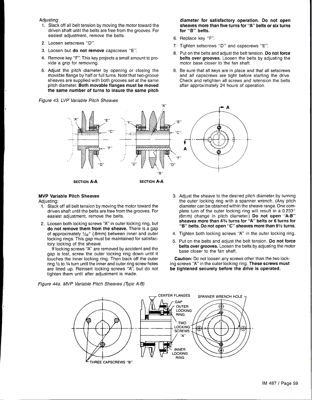
Adjusting:
l.-
Slack off all belt tension by moving the motor toward the
driven shaft until the belts are free from the grooves. For
easiest adjustment, remove the belts,
2.
Loosen setscrews “D”.
Loosen but do not remove capscrews “E”.
3.
4.
Remove key “F”. This key projects a small amount to provide a grip for removing.
Adjust the pitch diameter by opening or closinq the
5.
movable flange by half or full turns. Note that two-groove
sheaves are supplied with both grooves set at the same
pitch diameter, Both movable flanges must be moved
the same number of turns to insure the same pitch
diameter for satisfactory operation. Do not open
sheaves more than five turns for “A’ belts or six turns
for “B” belts.
6
Replace key “F”.
7.
Tighten setscrews “D” and capscrews “E”.
8
Put on the belts and adjust the belt tension. Do not force
belts over grooves. Loosen the belts by adjusting the
motor base closer to the fan shaft.
Be sure that all kevs are in place and that all setscrews
9.
and all capscrews are tight before starting the drive,
Check and retighten all screws and retension the belts
after approximately 24 hours of operation,
Figure 43. LVP Variable Pitch Sheaves
-.~,
..
:
,.
...
.1
..’
SECTION ~-~
,! --,
“c”
F“
,,,
;E
L.
L-.
,;
..’
SECTION
MVP Variable Pitch Sheaves
Adiustina:
1.’ Sla~k off all belt tension by moving the motor toward the
driven shaft until the belts are free from the grooves. For
easiest adjustment, remove the belts.
2. Loosen both locking screws “A” in outer locking ring, but
do not remove them from the sheave. There is a gap
of approximately 1/32” (.8mm) between inner and outer
locking rings. This gap must be maintained for satisfac-
tory locking of the sheave.
If locking screws “A” are removed by accident and the
gap is lost, screw the outer locking ring down until it
touches the inner locking ring. Then back off the outer
ring 1/2to3/4turn until the inner and outer ring screw holes
are lined up. Reinsert locking screws “A”, but do not
tighten them until after adjustment is made.
“N’
I
“E”
“c”
‘F”
\
0“ u
“B”
A-A
3. Adjust the sheave to the desired pitch diameter by turning
the outer locking ring with a spanner wrench. (Any pitch
diameter can be obtained within the sheave range. One complete turn of the outer locking ring will result in a 0.233”
(6mm) change in pitch diameter.) Do not open “A-B”
sheaves more than 43/4turns for “A’ belts or 6 turns for
“B” belts. Do not open “C” sheaves more than 91/2turns.
4. Tighten both locking screws “A” in the outer locking ring.
5. Put on the belts and adjust the belt tension. Do not force
belts over grooves. Loosen the belts by adjusting the motor
base closer to the fan shaft.
Caution: Do not loosen any screws other than the two lock-
ing screws “A” in the outer locking ring. These screws must
be tightened securely before the drive is operated.
Figure 44a. MVP Variable Pitch Sheaves (TYpe A-B)
_ CENTER FLANGES
SPANNER WRENCH HOLE
7
IM 487 I Page 59
Page 60

Figure 44b. MVP Variable Pitch Sheaves (Vpe C)
& BARREL FLANGE
E
G
s
CENTER FLANGE
ASSEMBLY
Final Control
When all start-up procedures have been completed, set the
controls and program the MicroTech controller for normal
operation. Use the following list as a guide; some items may
not apply to your unit.
1.
Turn system switch S1 to “On.”
2.
Turn gas furnace switch S3 to “Auto,” or turn electric heat
switch HS1 to “On. ”
Set the electromechanical (Honeywell H205) enthalpy
3.
control (OAE) as required (A, B, C, or D). Set the solidstate (Honeywell H705/C7400) enthalpy control (OAE/
RAE) past “D”.
4.
Set the heating and cooling control parameters as required (keypad menus 12 through 14).
5.
Set the high ambient heating lockout setpoint, “Max
OAT=” (keypad menu 14), as required.
6.
Set the alarm limits as required (keypad menu 15).
7.
Set the unoccupied heating and cooling setpoints as required (keypad menu 17).
8.
Set the duct static pressure control parameters as required (keypad menu 18).
9.
Set the fan tracking or building static pressure control
parameters as required (keypad menu 19).
10,
Set the economizer control parameters as required
(keypad menu 21).
Settings
points on dirty filter switches PC5 (filter) and PC6 (optional final filter). The maximum recommended settings
are 0.5” W.C. (124 Pa) for throwaway-type filters, 1.0” (249
Pa) W.C. for 30% pleat-type filters, and 1.5” W.C. (374 Pa)
for cartridge-type filters.
12.
Set the control timers as required (keypad menu 23).
13.
Set the date and time (keypad menu 24).
14.
Set the operating schedule as required (keypad menus
25 and 26).
15.
Place the unit into the Calibrate mode by selecting it from
keypad menu 11, “Control Mode.” Calibrate will automatically zero all pressure sensors and calibrate any actuator
feedback pots connected to the MicroTech controller.
When Calibrate is finished, set the control mode as
required.
Maintaining Control Parameter Records
It is recommended that the MicroTech controller’s setpoints
and parameters be recorded and saved for future reference.
If the Microprocessor Control Board ever requires replacement, this record will facilitate entering the unit’s proper data.
Using the following table, record the data directly on the pages
(with a pencil) or on photocopies of the pages. Keep this
record in a safe place and remember to update it whenever
further changes are made.
Page 60 / IM 487
Page 61
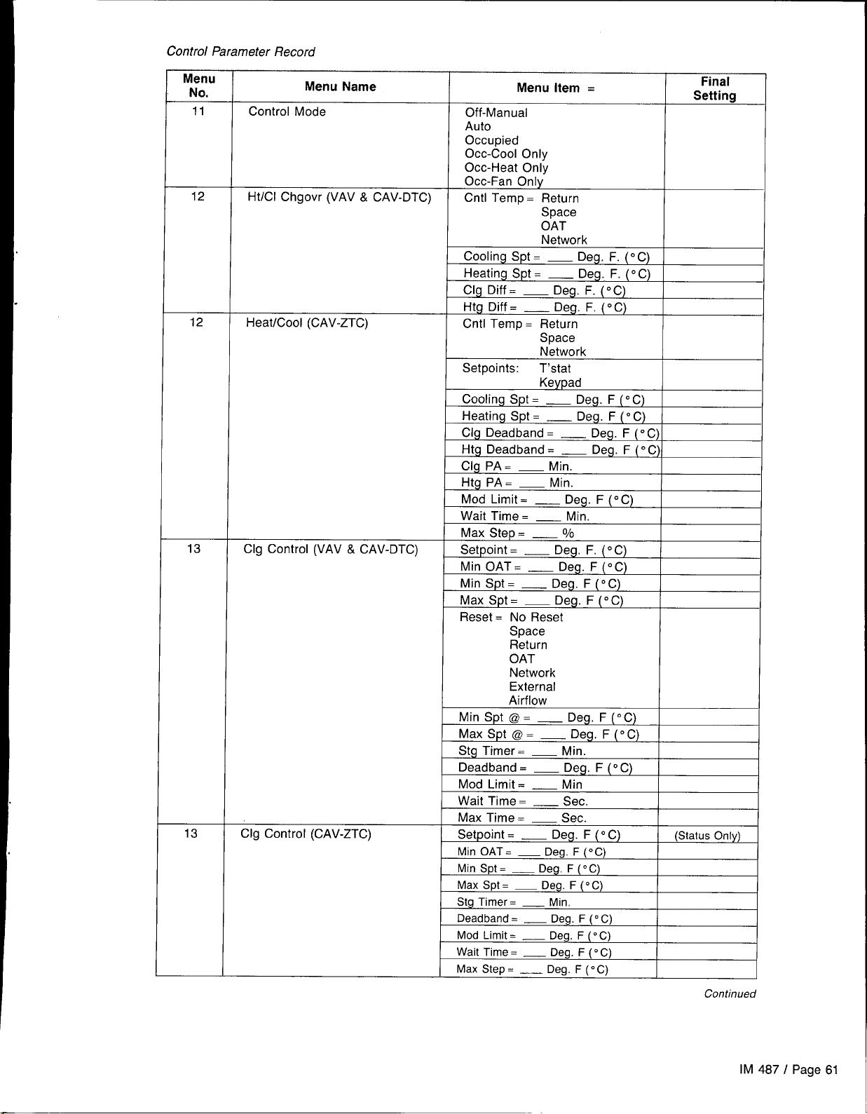
Control Parameter Record
Menu
No.
11
12
12
Menu Name
Control Mode
Ht/Cl Chgovr (VAV & CAV-DTC)
Heat/Cool (CAV-ZTC)
Menu item .
Off-Manual
Auto
Occupied
Occ-Cool Only
Occ-Heat Onlv
Occ-Fan Only’
Cntl Temp = Return
Space
OAT
Network
Cooling Spt =
Heating Spt =
Clg Diff =
Cooling Spt =
Heating Spt =
Clg Deadband =
Htg Deadband = _
_ Deg. F. (“C)
_ Deg. F. (“C)
_ Deg. F. (“C)
Keypad
_Deg. F(” C)
_Deg. F(” C)
Final
Setting
I
_ Deg. F (oC)I
Deg. F (“C)/
13
13
Clg Control (VAV & CAV-DTC)
Clg Control (CAV-ZTC)
Max Step = _
Setpoint = _ Deg. F. (“C)
L
Min OAT.
Min Spt =
Reset = No Reset
Space
Return
OAT
Network
External
Airflow
Min Spt @ =
Max Spt @. _ Deg. F(” C)
Stg Timer= _ Min.
Deadband =
Mod Limit =
Wait Time =
Max Time =
Setpoint = _ Deg. F(o C)
Mod Limit =
Wait Time =
Max Step = _
0/0
_ Deg. F (“C)
_Deg. F(° C)
_Deg, F(o C)
_ Deg. F(o C)
_ Min
— Sec.
— Sec.
_Deg. F(° C)
_Deg. F(” C)
Deg. F (“C)
(Status Only)
I
Continued
IM 487 I Page 61
Page 62

I Control Parameter Record
Menu
No.
14
14
15
17
18
19
19
Menu Name
Htg Control (VAV & CAV-DTC)
Htg Control (CAV-ZTC)
Alarm Limits
Unocc Htg/Clg
Duct Pressure (VAV)
Ret Fan Cntl (VAV with fan
tracking control)
Bldg Pressure
Menu Item =
Setpoint = _
Max OAT =
Min Spt =
Max Spt = —
Reset = No Reset
Space
Return
OAT
Network
External
Min Spt @ =
Max Spt @ = _
Stg Timer=
Deadband =
Mod Limit =
Wait Time =
Max Step =
Setpoint =
Max OAT= —
Min Spt=
Max Spt =
Stg Timer=
Deadband =
Mod Limit =
Wait Time = — Sec.
Max Step =
Hi Supply=
Lo SUpply =
Hi Return=
Cooling Spt =
Heating Spt =
Duct Spt —
Max Spt =
Ffeset = No Reset
Deadband =
Mod Lim =
Wait Time = — Sec
Max Step =
W/ Ex-SFMax = _
W/ Ex-RFMax =
W/ Ex-SFMin = _
W/ Ex-RFMin = _
No Ex-SFMax = _
No Ex-RFMax = _
No Ex-SFMin = _
No Ex-RFMin = _
Zone Spt = _
Deadbd =
Stg Timer= — Sec
Mod Lim =
Wait Time =
Max Step =
Deg. F (“C)
_Deg. F(° C)
_ Deg. F(o C)
Deg. F (“C)
_Deg, F(o C)
Deg. F (“C)
_ Min.
_Deg. F(o C)
_ Deg. F(” C)
— Sec.
— Sec.
_ Deg. F(o C)
Deg. F (“C)
_Deg. F(° C)
_ Deg. F(o C)
_ Min.
_Deg. F(o C)
_ Deg. F (“C)
— Sec.
_ Deg. F(o C)
_Deg. F (“C)
_ Deg. F(o C)
_Deg, F(o C)
_Deg. F (“C)
WC (Pa)
_ WC (Pa)
Network
Position
_ WC (Pa)
_ WC (Pa)
— Sec
— %
WC (Pa)
_ WC (Pa)
_ WC (Pa)
— Sec
— Sec
0/0
0/0
0/0
0/0
0/0
0/0
0/0
Final
Settirm
(Status Only)
Continued
1
page 62 / IM 487
Page 63

Control Parameter Record (cent ‘d)
Menu
No.
21
21
22
23
25
Menu Name
Outdr Damper (VAV)
Outdr Damper (CAV)
Dirty Filter
Timers
Schedule
Menu item =
Min Airflow. _
Auto Adjust = None
Auto
Enthalpy = Yes
No
Changeover. _
Max Purge =
_ Min
Deadband. _
Mod Limit. _
Wait Time =
— Sec
Max Step. _
Min Airflow. _
Enthalpy = Yes
No
Changeover. _
Max Purge =
_ Min
Deadband. _
Mod Limit. _
Wait Time =
Max Step =
Ist Fltr. _
Fnl Fltr = _
Recirc =
— Sec
— Sec
WC (Pa)
WC (Pa)
_ Min
Ovrde Inc = _ Hr
Max MWUP.
_ Min
override = _ Hr
NMP Sched No. = _
Sun hr:mn-hr.mn
Mon hr:mn-hr. mn
Tue hr:mn-hr. mn
Wed hr:mn-hr.mn
Thu hr:mn-hr.mn
Fri
hr:mn-hr.mn
Sat hr:mn-hr,mn
Hol hr:mn-hr.mn
Final
Setting
0/0
Deg. F (“C)
Deg. F (“C)
Deg. F (“C)
Sec
0/0
Deg. F (“C)
Deg. F (“C)
Deg. F (“C)
Continued
IM 487 I Page 63
Page 64
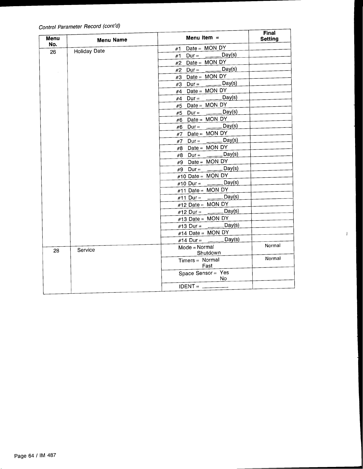
Control Parameter Record (cent’d)
Menu
No.
26
28
Holiday Date
Service
Menu Name
Menu Item =
#l Date= MON DY
#1 Dur=
—Day(s)
#2 Date= MON DY
#2 Dur =
#3 Date=
#3 Dur=
— Day(s)
MON Dy
— Day(s)
#4 Date= MON DY
#4 Dur= —Day(s)
#5 Date= MON Dy
#5 Dur=
— Day(s)
#6 Date= MON DY
#6 Dur=
— Day(s)
#7 Date. MON DY
#7 Dur=
— Day(s)
#8 Date= MON DY
#8 Dur=
— Day(s)
#9 Date= MON DY
#9 Dur=
—Day(s)
#10 Date = MON DY
#lo Dur=
— Day(s)
#11 Date = MON DY
#11 Dur=
— Day(s)
#12 Date = MON D’f
#12 Dur=
#13 Date = MON DY
#13 Dur=
— Day(s)
— Day(s)
#14 Date = MON DY
#14 Dur=
—Day(s)
Mode = Normal
Shutdown
Timers = Normal
Fast
space Sensor = Yes
No
IDENT =
Final
Setting
Normal
Normal
page 64 I IM 487
Page 65

Maintenance
Installation and maintenance are to be performed only by qualified personnel who are experienced with this type
of equipment and familiar with local codes and regulations.
I
I
Moving machinery and electrical power hazards. May cause
severe personal injury or death.
Disconnect and lock off power before servicing equipment.
Preventive
Preventive maintenance is the best way to avoid unnecessary
expense and inconvenience, Have this system inspected at
regular intervals by a qualified service technician. The required frequency of inspections depends upon the total operating time and the indoor and outdoor environmental conditions, Routine maintenance should cover the following items:
Tighten all belts, wire connections, and setscrews.
1.
2.
Clean the evaporator and condenser coils mechanically
or with cold water, if necessary. Usually any fouling is only
matted on the entering air face of the coil and can be
removed by brushing.
Lubricate the motor and fan shaft bearings (see below).
3.
Align or replace the belts as needed.
4.
5.
Clean or replace the filters as needed.
Unit Storage
If air handling units are to be stored for any period of time,
it is important to periodically rotate the fan wheel. The fan
wheel needs to be rotated to prevent any deflection in the fan
shaft which could cause unbalanced fan operation. Also it
Sharp edges are inherent to sheet metal parts, screws, clips,
and similar items. May cause personal injury.
Exercise caution when servicing equipment.
Maintenance
6.
Check for blockage of the condensate drain. Clean the
condensate pan as needed.
7.
Check the power and control voltages,
8,
Check the running amperage of all motors.
9.
Check all operating temperatures and pressures,
10.
Check and adjust all temperature and pressure controls
as needed.
11.
Check and adjust all damper linkages as needed.
12.
Check the operation of all safety controls.
13.
Examine the gas furnace (see Bulletin No, IM 484),
14.
Lubricate the door latch mechanisms,
is important to keep the fan bearings lubricated. If the fan
wheel is not periodically rotated, grease will settle in the lower
part of the bearing. This can lead to oxidation on the upper
portion of the bearing surface which can cause bearing failure,
Gas Furnace
For information on maintenance of the gas furnace, refer to Bulletin No. IM 484,
Bearing Lubrication
Bearing overheating potential. Can cause damage to the equipment.
Do not overlubricate bearings.
Use only a high grade mineral grease with a 200F (93” C) safe operating temperature, Refer to Table 13 for specific recommended
lubricants.
Motor Bearings
Supply and Return Fans
Supply and return fan motors should have grease added after
every 2,000 hours of operation. Use one of the greases shown
I
in Table 13 on page 66. Using the following procedure, relubricate the bearings while the motor is warm, but not running.
1. Remove and clean upper and lower grease plugs.
2. Insert a grease fitting into the upper hole and add a small
amount of clean grease with a low pressure gun.
3. Run the motor for five minutes before replacing the plugs.
Note: Specific greasing instructions may be found on a tag
attached to the motor. If special lubrication instructions are
on the motor, they will supersede all other instructions,
487 I Page 65
IM
Page 66
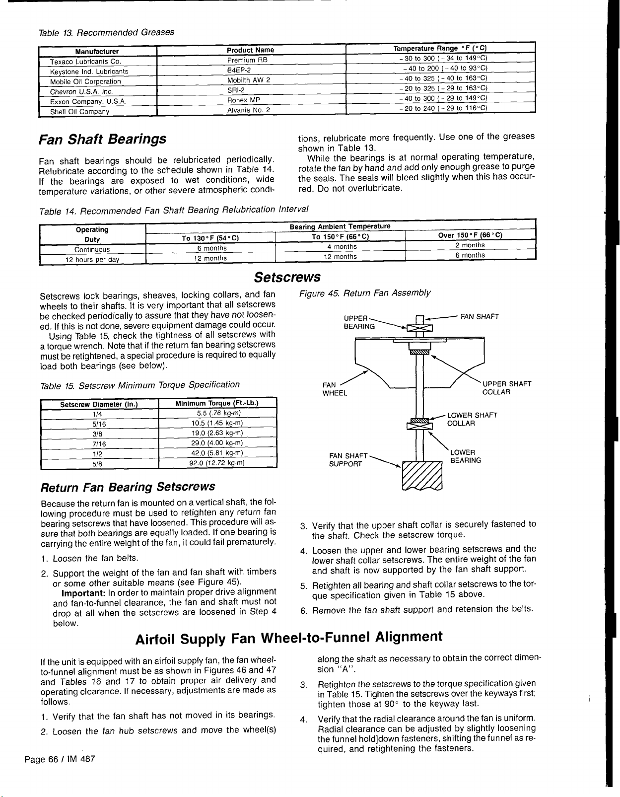
Table 13. Recommended Greases
Manufacturer
Texaco Lubricants Co.
Keystone Ind. Lubricants
Mobile Oil Corporation
Chevron U.S.A. Inc.
Exxon Company, U.S.A.
Shell Oil Company
Product Name
Premium RB
B4EP-2
Mobilth AW 2
SRI-2
Ronex MP
Alvania No. 2
Temperature Range 0F (“C)
-30to 300 (-34to 149”C)
-40 to 200 (-40 to 93”C)
-40 to 325 (-40 to 163”C)
-20 to 325 (-29 to 163° C)
-40 to 300 (-29 to 149”C)
-20t0240( -29to116°C)
Fan Shaft Bearings
Fan shaft bearings should be relubricated periodically.
Relubricate according to the schedule shown in Table 14.
If the bearings are exposed to wet conditions, wide
temperature variations, or other severe atmospheric condi-
Table 14. Recommended Fan Shaft Bearing Relubrication Interval
Operating
Duty
Continuous
12 hours per day
TO 1300F (54” C)
6 months
12 months
Bearing Ambient Temperature
Setscrews
Setscrews lock bearings, sheaves, locking collars, and fan
wheels to their shafts. It is very important that all setscrews
be checked periodically to assure that they have not loosened. If this is not done, severe equipment damage could occur.
Using Table 15, check the tightness of all setscrews with
a torque wrench. Note that if the return fan bearing setscrews
must be retightened, a special procedure is required to equally
load both bearings (see below).
Table 15. Setscrew Minimum Torque Specification
Setscrew Diameter (In.)
114
5/16
318
7116
112
518
Minimum Torque(Ft.-Lb.)
kg-m)
5.5 (.76
10.5 (1.45 kg-m)
19.0 (2.63 kg-m)
29.0 (4.00 kg-m)
42.0 (5.81 kg-m)
92.0 (12.72 kg-m)
tions, relubricate more frequently. Use one of the greases
shown in Table 13.
While the bearings is at normal operating temperature,
rotate the fan by hand and add only enough grease to purge
the seals. The seals will bleed slightly when this has occurred. Do not overlubricate.
TO 150” F (66° C)
4 months
12 months
Over 1500 F (66 “C)
2 months
6 months
Figure 45.
I
FAN UPPER SHAFT
WHEEL COLLAR
AFT
FAN SHAFT
SUPPORT
Return Fan Bearing Setscrews
Because the return fan is mounted on a vertical shaft, the following procedure must be used to retighten any return fan
bearing setscrews that have loosened. This procedure will assure that both bearings are equally loaded. If one bearing is
carrying the entire weight of the fan, it could fail prematurely.
Loosen the fan belts.
1.
2.
Support the weight of the fan and fan shaft with timbers
or some other suitable means (see Figure 45).
Important: In order to maintain proper drive alignment
and fan-to-funnel clearance, the fan and shaft must not
drop at all when the setscrews are loosened in Step 4
below.
Airfoil Supply Fan Wheel-to-Funnel Alignment
If the unit is equipped with an airfoil supply fan, the fan wheelto-funnel alignment must be as shown in Figures 46 and 47
.-
.-.
and Tables-16 and 17 to obtain proper air delivery and
operating clearance. If necessary, adjustments are made as
follows.
1. Verify that the fan shaft has not moved in its bearings.
2. Loosen the fan hub setscrews and move the wheel(s)
Page 66 I IM 487
Verify that the upper shaft collar is securely fastened to
3.
the shaft. Check the setscrew torque.
Loosen the upper and lower bearing setscrews and the
4.
lower shaft collar setscrews. The entire weight of the fan
and shaft is now supported by the fan shaft support.
Retighten all bearing and shaft collar setscrews to the tor-
5.
que specification given in Table 15 above.
Remove the fan shaft support and retension the belts.
6.
along the shaft as necessary to obtain the correct dimension “A”.
3. Retighten the setscrews to the torque specification given
in Table 15. Tighten the setscrews over the keyways first;
tighten those at 90° to the keyway last.
. .
4. Verify that the radial clearance around the fan is uniform.
Radial clearance can be adjusted by slightly Ioosening
the funnel hold]down fasteners, shifting the funnel as required, and retightening the fasteners.
Page 67

Figure 46, 27”-40” Airfoil Wheel-to-funnel Tolerances
\
FUNNEL<
/
Figure 4T 44” & 49” Airfoil Wheel-to-Funnel Alignment
/-WHEEL
_ WHEEL.
--/ +A
!-- ‘w’ --+
Table 16, Airfoil Wheel-to-Funnel Tolerances
Wheel-to-Funnel Relationship
Wheel Diameter
(in Inches)
27
30 .31” ( 8mm)
33
36
40
.31” ( 8mm)
.31” ( 8mm)
.44” (Ilmm)
.62” (18mm)
,, ,>
A
Table 17.44” & 49” Airfoil Wheel-to-Funnel Alignment
Wheel-to-Funnel Relationship
Wheel Dia. (In.)
44 16.21 (412mm)
I
49
I
“A” (In Inches)
17.81 (452mm)
Winterizing Coils
Coil freeze-up can be caused by such things as air stratifica-
tion and failure of outdoor dampers and/or preheat coils. coil. Due to a small amount of water always remaining in each
Routine draining of water cooling coils for winter shutdown
cannot be depended upon as insurance against freeze-up.
Severe coil damage may result. It is recommended that all
coils be drained as thoroughly as possible and then treated
in the following manner.
Fill each coil independently with an antifreeze solution us-
ing a small circulating pump and again thoroughly drain.
Check freezing point of antifreeze before proceeding to next
coil, there will be a diluting effect. The small amount of antifreeze solution remaining in the coil must always be concentrated enough to prevent freeze-up. Note: Carefully read
instructions for mixing antifreeze solution used, Some products will have a higher freezing point in their natural state
than when mixed with water.
I
Service and Warranty Procedure
In-Warranty Return Material Procedure
Material may not be returned except by permission of
authorized factory service personnel of McQuay International
at Minneapolis, Minnesota.
A “return goods” tag will be sent to be included with the
returned material, Enter the information as called for on the
tag in order to expedite handling at our factories and issuance
of credits. All parts shall be returned to the factory designated
on the return goods tag, transportation charges prepaid.
Replacement Parts
When writing to McQuay for service or replacement parts,
provide the model number, serial number, and G.0, number
of the unit as stamped on the serial plate attached to the unit.
For questions regarding wiring diagrams, it will be neces-
The return of the part does not constitute an order for
replacement. A purchase order for the replacement part must
be entered through your nearest McQuay representative. The
order should include the component’s part number and
description and the model and serial numbers of the unit
involved,
If it is determined that the failure of the
returned part is due
to faulty material or workmanship, credit will be issued on
the customer’s purchase order.
sary to provide the number on the specific diagram. If replace-
ment parts are required, include the date of unit installation,
the date of failure, an explanation of the malfunction, and a
description of the replacement parts required,
\
IM 487 / Page 67
L
Page 68

Product Warranty
McQuay International, hereinafter referred to as the “Company,” warrants that it will provide, at the Company’s option,
either free replacement parts or free repair of component parts
in the event any product manufactured by the Company and
used in the United States proves defective in material or
workmanship within twelve (12) months from initial start-up
or eighteen (18) months from the date shipped by the Company, whichever comes first. For an additional consideration,
the Company warrants that for nine (9) years following the
initial warranty period it will provide free replacement of the
heat exchanger in gas-fired or oil-fired furnaces which proves defective in material and workmanship. (Extended warranties for heat exchangers are not applicable unless
separately purchased.)
To obtain assistance under the parts warranty or extended
heat exchanger warranty, simply contact the selling agency.
To obtain information or to gain factory help, contact McQuay
International, Warranty Claims Department, PO. Box 1551,
Minneapolis, MN 55440; telephone (612) 553-5330.
This warranty constitutes the buyer’s sole remedy. It is
given in lieu of all other warranties. There is no implied
warranty of merchantability or fitness for a particular purpose. In no event and under no circumstances shall the
Company be liable for incidental or consequential
damages, whether the theory be breach of this or any
other warranty, negligence or strict tort.
This parts warranty and the optional extended warranties
extend only to the original user. Of course, abuse, misuse,
or alteration of the product in any manner voids the Company’s warranty obligation. Neither the parts nor extended
warranty obligates the Company to pay any labor or service
costs for removing or replacing parts, or any shipping charges.
Refrigerants, fluids, oils, and expendable items such as filters
are not covered by this warranty.
The extended warranties apply only to integral components
of the heat exchanger, not to refrigerant controls, electrical
controls, or mechanical controls, or to failures caused by
failure of those controls.
Attached to this warranty is a requirement for equipment
containing furnaces to report start-up information. The
registration form accompanying the product must be completed and returned to the Company within ten (10) days of
original equipment start-up. If that is not done, the date of ship-
ment shall be presumed to be the date of start-up, and the
warranty shall expire twelve (12) months from that date.
No person (including any agent, salesman, dealer or
distributor) has authority to extend the Company’s obligation
beyond the terms of this express warranty, or to state that the
performance of the product is other than that published by
the Company,
/
MeQuaY”
13600 Industrial Park Boulevard, P.O. Box 1551, Minneapolis, MN 55440 USA (612) 553-5330
@Printedcm recycled papercontaining at least 10%post-consurner recycled material
October 1996
 Loading...