

Page 1
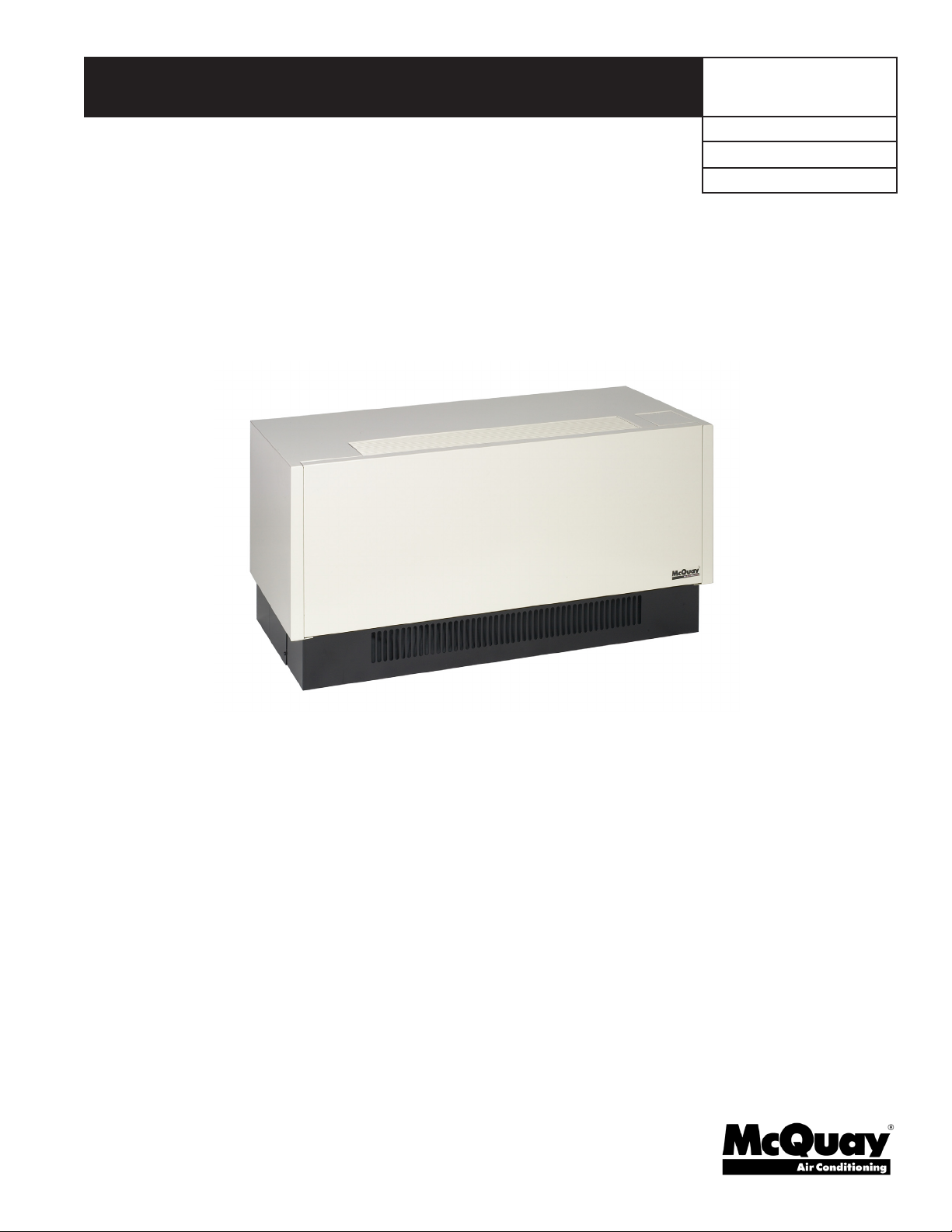
Installation & Maintenance Data
Group: PTAC
Part No.: 910109975
Date: July 2010
EnerSaver™ Packaged Terminal
Air Conditioners and Heat Pumps with R-410A Refrigerant
Model PNES3 “A” Design
IM 1079
Table of Contents
Receiving Equipment .....................................................................2
Model Nomenclature ......................................................................3
Installation Instructions
Louver Frame ..................................................................................3
Wall Sleeve Extension ....................................................................4
Subbase ...........................................................................................5
Wall Guard Flange ..........................................................................6
Hydronic Piping ..............................................................................7
Room Cabinet/Wall Sleeve .............................................................8
Condensate Drain Kit ......................................................................9
Chassis ..........................................................................................10
Front Panel ....................................................................................11
Climate Director Plenum ..............................................................11
© 2010 McQuay International
Unit Start-up
Electrical Connections ..................................................................12
Outside Air Damper ......................................................................12
Check, Test & Start Form ...................................................... 13-14
Unit Maintenance and Operation ..............................................15
Specic Operating Conditions ..................................................16
Typical Schematics .......................................................................16
Wall Thermostat Adjustment ......................................................18
AC Retrot With HP Chassis ......................................................18
Troubleshooting ...................................................................... 19-21
Page 2
Receiving Equipment
Before signing the freight bill, carefully examine the units and
note any shortages or damages on the freight bill. The purchaser
is responsible for ling the necessary claims with the carrier.
Concealed damage which was not discovered until after unloading
should be reported to the carrier within 15 days after receipt.
McQuay’s responsibility ceases upon delivery of material in
good order to a carrier.
To help avoid concealed damage, the units must be shipped,
handled, and stored right side up as clearly marked on the
container. If the units must be stored prior to installation, they
should be stored within the carton in a clean, dry, protected area.
When ready for installation, save the carton and use the carton
shell to protect the cabinets until construction, painting, etc., is
completed.
A complete EnerSaver unit is normally shipped in two cartons:
one carton contains the cabinet/wall sleeve, front panel, louver
and subbase; the other carton contains the integrated chassis.
Cabinet/ Wall Sleeve
The EnerSaver cabinet/ wall sleeve is available in two sizes, 37½"
(952mm) or 41½" (1054mm) long. This one-piece cabinet/wall
sleeve functions as both the wall box as well as the room cabinet
once the front panel is in place. Units with hydronic heat always
utilize the long cabinet. The hydronic coil is factory mounted
to the cabinet/ wall sleeve. Electric heat models are available in
either size cabinet. Units ordered with either the stamped or the
extruded aluminum louver are shipped with the louver factory
mounted. Stamped anged louvers must be eld mounted after
the room cabinet/wall sleeve is in place.
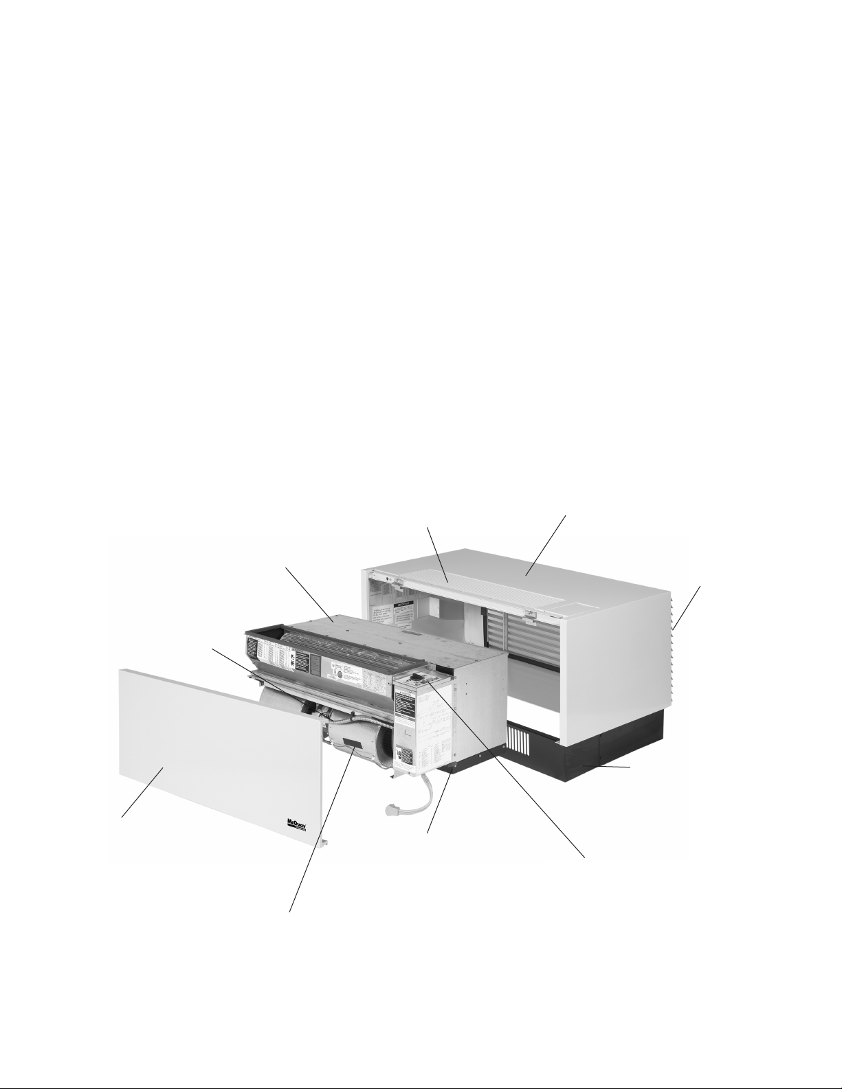
Chassis
The chassis is a completely self-contained, integrated
heating/ cooling/ ventilation center. It houses the refrigeration
components , air handling components, electric heater
(if applicable), and controls. A single integrated chassis requires
less on-site handling during installation and service periods.
Figure 1: EnerSaver Features
Ventilation Control
Manual damper standard on
electric and heat pump chassis.
Motorized damper standard
on hydronic chassis.
Fan Motors
Both indoor and outdoor fan motors
are PSC for superior quality and
greater reliability.
Front Access Panel
Heavy gauge steel with
powder paint coating provides
maximum scratch and dent
resistance and minimizes
vibration for quieter operation.
Indoor Fan Wheels
Large diameter to provide
improved airow and quiet operation.
Heavy Duty Grille
Factory mounted,
“pencil proof” bar stock
discharge grille.
Base Pan
One-piece base pan and
one-piece bulkhead provide
weather tightness and water
integrity.
Room Cabinet/Wall Sleeve
Heavy gauge steel with
powder paint coating provides maximum
scratch and dent protection and resists
corrosion.
Outside Air Louver
Factory mounted
extruded aluminum
to resist weathering.
Subbase
Heavy duty steel with
powder coated paint
to resist corrosion.
Electro-mechanical Controls
Reliable and easy to operate.
Easily adaptable to energy
management systems.
IM 1079 / Page 2 of 24
Page 3
Model Nomenclature
P NES 3 009 C Z 35 Z 12 AR 14 C 1 A 1
Model
Product Category
P= PTAC
Product Style
1 = 1st Style Change
Product Identier
NES = Enersaver Air Conditioner w/
Electric or Hydronic Heat
NHS = Enersaver Heat Pump
w/ Electric Heat
Design Series
3 = A design - Enersaver
4 = B design Enersaver
Nominal Capacity - Btuh
009 = 9,000
012 = 12,000
015 = 15,000 (AC Only)
Voltage
A = 115 - 60 - 1 (Hydronic AC Only)
C = 208 - 60 - 1
G = 230 - 60 - 1
J = 265/277 - 60 - 1
Coil Options
Z = None
Heating Options
00 = None
35 = 2.5 kW nominal
41 = 3.5 kW nominal
44 = 4.0 kW nominal
62 = Hydronic - Normally Open Valve (hot water or steam)
for EnerSaver “A” Design
63 = Hydronic - Normally Closed Valve (hot water or steam)
for EnerSaver “B” Design
Hand Orientation
Z = Not Applicable
SKU
A = Stock
B = Standard
Delivery
C = Extended
Leadtime
Color
1 = Antique Ivory
Power Connection
C = Cord
Return Air/
Outdoor Air
14 = Bottom
Discharge
AR = Flat Top
Controls
12 = Unit Mounted Manual
Changeover (MCO)
13 = Remote Thermostat Setup
24 = Unit Mounted Manual
Changeover (MCO)
& Night Setback (NSB)
Note: Availability of voltages, heating options, and controls may vary amongst unit sizes. Consult your McQuay representative.
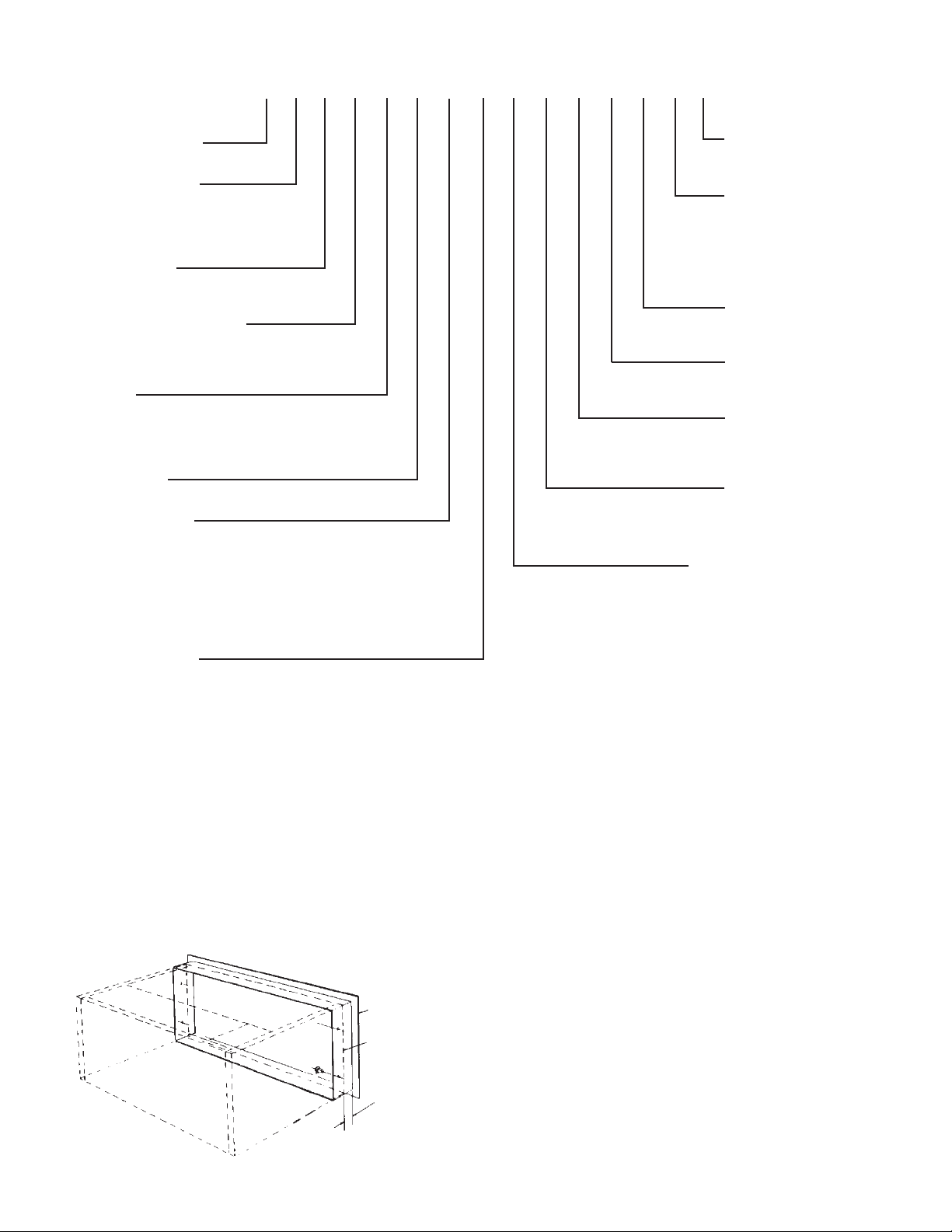
Installation Instructions
Louver Frame
When a louver frame is used, it must be installed prior to the
room cabinet/ wall sleeve, and it must be level and square (see
Figure 2). If the louver frame is to be installed in a panel wall,
install it at the same time as the room cabinet/wall sleeve.
1. Apply caulking compound on the surfaces of the louver
frame’s four anges which will come in contact with the
wall. Add caulking as required for weather tight seal.
Figure 2: Louver Frame Installation
Intake Collar
Cabinet/Wall Sleeve
2. Place the louver frame in the wall opening from the
exterior of the building, and apply rm pressure so that
the caulked frame anges are snug against the exterior
of the building. Secure the louver frame to the wall if
desired.
3. Secure the louver frame to the wall through the sides and
top. Never secure the frame through the bottom as it can
cause leaks.
4. Coordinate the remaining instructions with the room cabinet/wall sleeve installation instructions.
5. Drill four (4) 1/8" (3mm) diameter holes through the sides
of the wall sleeve and through the ange of the louver
frame. Attach the collar with four (4) #8 x 3/8 self-tapping
screws provided. Do not drill holes in the bottom of the
wall sleeve.
6. Caulk the seam between the louver frame and the wall
watertight.
3" (76mm)MAX
IM 1079 / Page 3 of 24
Page 4
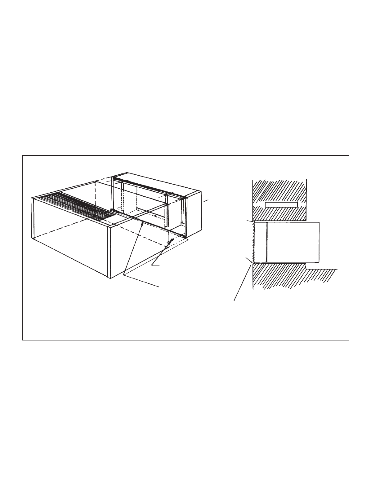
Wall Sleeve Extension
1. When a wall sleeve extension is used, assemble it and the
wall sleeve, then place them in the wall as a unit.
2. In cases where the louver is already installed in the
cabinet/wall sleeve, remove it from the wall sleeve before
installing the extension.
3. Check the tagging of the wall sleeve extension to be sure
it corresponds with the correct unit location.
4. Before attaching the wall sleeve extension to the wall
sleeve, run a bead of caulking around the outside ange
of the wall sleeve where it attaches to the extension,
making a watertight seal.
Figure 3: Wall Sleeve Installation
5. Align the predrilled mounting holes of the wall sleeve
extension with those of the wall sleeve (the louver mounting holes), and rmly attach these two parts with the six
(6) self-tapping screws provided with the wall sleeve
extension.
6. Recheck caulking to ensure that all seams are watertight.
7. Refer to the wall sleeve installation instructions on page
8 for installation of the wall sleeve and extension into the
wall.
Wall Sleeve
Extension
Wall Depth
Caulk (by others)
Caulk (by others)
1. Attach the extension with the self
tapping screws provided, through
the slots in the rear of the cabinet/
wall sleeve.
2. Caulk the inside perimeter of
the cabinet/wall sleeve/extensionwatertight.
3. After installation, caulk the
exterior perimeter of the
extension/wall watertight.
Cabinet/Wall
Sleeve
Extension
IM 1079 / Page 4 of 24
Page 5
Subbase
When a subbase is used, it must be installed prior to the room
cabinet/wall sleeve. Consult the instructions shipped with the
subbase for proper installation.
1. When removing the subbase from the shipping carton
remove the two (2) shipping bolts and sheet metal nuts.
Do not throw away the shipping bolts; they are used as
subbase leveling bolts.
2. The electrical subbase assembly contains the unit receptacle and junction box. Therefore, before installing the
subbase to the cabinet/wall sleeve, it will be necessary to
run the power wiring from the stub-in and attach it to the
subbase receptacle.
3. The subbase assembly comes in two (2) parts:
a. A front section which bolts to the cabinet/wall sleeve.
b. End ller pieces, which telescope to t ush
against the wall.
Figure 4: Subbase Installation
4. Attach the front section of the subbase to the cabinet/wall
sleeve with the furnished nuts, screws and lock washers
using holes provided as attachment points. Install the two
(2) star washers provided as shown in the illustration to
provide a ground path between the cabinet/wall sleeve
and the subbase.
5. Coordinate the remaining instructions with the room cabinet/wall sleeve installation instructions.
6. After the cabinet/wall sleeve is fastened in the wall,
position the end ller pieces so they are tight against the
wall. Then, using the two (2) holes as a template, drill two
(2) 11/64" (4.4mm) diameter holes into the front section
of the subbase. Attach the two end llers, using the selftapping screws provided.
Standard Subbase
Leveling Bolts
Electrical Subbase
Attach Front of Subbase to
Cabinet/Wall Sleeve Using
Holes Provided
(See item 4 above)
Attach Rear Section with
(2) #10- 24 × 3/8" Self-Tapping Screws
Provided (See item 6 Above)
IM 1079 / Page 5 of 24
Page 6
Wall Guard Flange
1. The wall guard ange is shipped disassembled and is
normally taped to the inside of the cabinet/wall sleeve.
2. Mounting the wall guard ange before the cabinet/wall
sleeve is installed:
a. Locate the rear edge of the wall guard ange at the
position that corresponds to the inside nished wall line.
b. Using the holes in the wall guard ange as a template,
drill eleven (11)1/8" (3mm) diameter holes in the cabinet
wall sleeve and attach the wall guard ange to the
cabinet/wall sleeve with the eleven (11) #8 x 3/8 selftapping screws furnished.
Figure 5: Wall Guard Flange Installation
3. Mounting the wall guard ange after the cabinet/wall
sleeve is installed:
a. Position the wall guard ange so that the rear edge is
tight against the inside nished wall surface.
b. Measure the distance from the front of the cabinet/
wall sleeve to the front edge of the wall guard ange
and add 1/2" (13mm). At this dimension from the
front of the cabinet/wall sleeve, drill eleven (11)1/8"
(3mm) diameter holes from the inside of the cabinet/
wall sleeve through the angle of the wall guard ange
spacing them approximately 6" to 8" (153mm to
203mm) as shown. Attach the wall guard ange to
the cabinet/wall sleeve with the eleven (11) #8 x 3/8
self-tapping screws provided.
Locate the Rear Edge of the Wall
Guard Flange Top and End Sections
at the Finished Wall Line
20" (508mm) Max.
8" (203mm) Min.
Top Wall Guard Flange
Optional Subbase
Cabinet/Wall Sleeve
End Wall Guard Flange
Note 2
Note 3
Wall Guard Flange
(Flange for Interior Wall Finish)
IM 1079 / Page 6 of 24
Intake Collar
(Flange for Exterior Wall Opening)
Page 7
Hydronic Piping
1. Stub hot water or steam piping through oor prior to
installation of room cabinet/wall sleeve.
3. Install valve. Use soft solder only. Refer to the installation
instructions packed with each valve.
2. After the room cabinet/wall sleeve is installed, complete
the piping. Piping must not extend to the right beyond the
chassis guide rail in the bottom of the cabinet/wall sleeve.
Figure 6: Hydronic Piping Installation
Air Vent if Required
(by others)
Return
4. After all piping is complete and chassis is installed,
connect wiring to the valve. Plug connection is provided
on wiring which hangs from the left side of the chassis.
Supply
Hydronic Coil (Factory Mounted in Cabinet/Wall Sleeve)
Cabine/Wall Sleeve
Wire Harness
Shutoff Valves (by others)
Coil Supply and Return Connections
are 5/8" O.D. Female Sweat
Motorized Valve (AAF). Standard Piping For Hot Water Shown. For Steam
System, Steam Trap By Others Required in Return Line.
IM 1079 / Page 7 of 24
Page 8
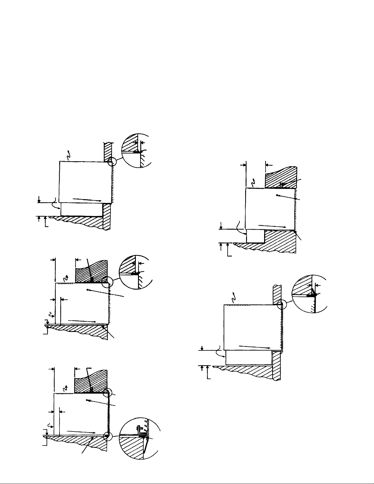
Room Cabinet/ Wall Sleeve
1. Where applicable, install the louver frame, wall sleeve
extension, subbase, and/or wall guard ange as per prior
installation instructions.
2. For masonry installations, set the room cabinet/wall
sleeve in soft mortar.
3. Position the room cabinet/wall sleeve in the wall opening.
Where applicable, align with louver frame. See Figures
7 through 11 and associated notes for various installations.
4. Where applicable, level the subbase with the leveling
bolts provided.
Figure 7: Panel Construction, Bottom Inlet, Extruded Louver
Discharge
Return
Air
Inlet
5"(127mm)
Min.
Finished Floor Line
Slope 1° Max.
Subbase
(See Note 3)
Figure 8: Masonry Construction, Front Inlet, Extruded Louver
Masonry Lintels
8"
Min.
3" (76mm)
Slope 1° Max.
By Others
See
Note 4
Fasteners By Others
Standard Louver
Installation Shown
Mortar Bed or Rigid Insulation
Board
(203mm)
Discharge
Return
Air Inlet
See Note 5
Finished
Floor Line
1/4" (6mm) Min.
Caulk
By Others
1/4" (6mm)
Min. Caulk By
Others
5. After the room cabinet/wall sleeve is installed and
leveled, secure the louver frame to the wall with screws
driven through the sides and top of the room cabinet/wall
sleeve outward through the louver frame. Never secure
the frame through the bottom, as it can cause leaks.
6. Caulk the outdoor joint between the room cabinet/wall
sleeve and the louver frame: top, bottom, and both sides.
Do not permit caulking to block the weep holes.
7. Install the outdoor louver. Holding the louver with a wire
loop, or other similar means, push the louver out through
the rear opening in the room cabinet/wall sleeve and pull
the louver back to the rear face so that the louver studs
pass through the holes in the room cabinet/wall sleeve
ange. Attach the louver with the washers and nuts
provided, and securely tighten the louver in place.
Figure 10: Masonry Construction, Bottom Inlet, Extruded
Louver
Return
Air
Inlet
5"(127mm)
Min.
Finished Floor Line
Figure 11. Panel Construction, Bottom Inlet, Stamped
Flanged Louver
Discharge
Return
Air
Inlet
8"
(203mm)
Min.
Discharge
Slope 1° Max.
Subbase
(Optional)
Slope 1° Max.
Masonry Lintels
By Others
Fasteners By Others
Flush Louver
Installation Shown
1/4" (6mm)
Min. Caulk
By Others
See
Note 4
Standard Louver
Installation Shown
Figure 9: Masonry Construction, Front Inlet, Stamped
Flanged Louver
(203mm)
Min.
Discharge
Return
Air Inlet
See Note 5
Finished
Floor Line
Mortar Bed or Rigid Insulation Board
IM 1079 / Page 8 of 24
8"
3" (76mm)
Slope 1° Max.
Masonry Lintels By Others
See Detail
Fasteners By Others
Caulk By
Others
5"(127mm)
Min.
Finished Floor Line
Notes:
1. Recommended wall openings are 16½" x 38" (419mm x 965mm) for short
cabinets and 16½" x 42" (419mm x 1067mm) for long cabinets.
2. Set the cabinet level side to side and level to no more than 1° slope
downward toward outside, front to back.
3. Fasten the cabinet/wall sleeve to the wall when possible. Do not fasten the
cabinet/wall sleeve through its bottom.
4. Regardless of the type of wall construction, the cabinet/wall sleeve must be
eld caulked to the wall around the top, bottom, and both sides, to form an
airtight and watertight weather seal. For ush louver installation, if the wall
material at the opening is not watertight, framing or ashing must be provided
around the wall opening (by others) to prevent penetration of water into the wall.
5. 1/2" (13mm) minimum for power cord (short cabinet only). Caution: If the
conditioned space is carpeted, increase this dimension to 3/4" (19mm)
minimum for long cabinets or to 1¼" (38mm) minimum for short cabinets.
Subbase
(See Note 3)
Page 9

Heat Pump Condensate Drain Kit (P/N 105542401)
Install the condensate drain kit at the same time as the chassis
is being installed.
1. If the application requires a drain exit through the bottom
of the wall sleeve, punch through the knockout provided.
2. Holes in the cabinet/wall sleeve, other than the knockout,
must be provided by others.
3. Slip the 5/8" (16mm) rubber tube over the end of the
drain tube elbow, locate the drain tube in the desired
position, and slip the open end of the rubber tube over the
chassis drain pan elbow. The rubber tube must engage the
copper elbows a minimum of 1/2" (13mm). Installation of
the drain piping must allow clearance for the lter which
ts under the drain connection.
Figure 12: Heat Pump Condensate Drain Connection
Left Side of
Cabinet/
Wall Sleeve
23/32" 18mm)
71/4" (184mm)
Long Cabinet (411/2")
31/4" (83mm)
Short Cabinet (371/2")
Lower Left-Hand Front View
(Front Panel Removed)
Condensate
Drain
4. Maintain a downward pitch in the drain line, away from
the drain pan.
5. Connect drain pipe to condensate removal piping system
or extend to exterior of building.
6. Test drain operation by pouring approximately (2) quarts
of water into drain and assure proper removal.
7. The drain valve is thermostatically controlled: full open at
60°F (1600), full closed at 80°F (2700).
Figure 13: Condensate Drain Connection Detail
3/4" (19mm) Dia. Hole (by
others) 1/2" (13mm) Up from
Bottom Caulk Water Tight When
Drain is Thru Rear of Cabinet
5/8" Copper Tube Assembly
Thru End Panel into Wall
(Hole by others)
Down Thru Wall
Knockout
Provided
5/8" Rubber Tube
(Hole by others)
Drain Pan Elbow
Lintel By Others
(13mm)
Extruded
Louver
Shown
1/2"
Condensate Drain
Left End View
Finished Wall Surface
8"
(203mm)
Min.
1¾"
(44mm)
7¼"
(184mm)
Optional
Subbase
3/4" (11mm)
1½" (38mm)
Chassis
Cabinet Front
Panel
23/32" (18mm)
Return Air
Inlet
Trap By Others
Notes:
1. Condensate drain piping must be connected to the condensate drain as shown
in Figure 13.
2. A condensate piping kit is available from McQuay.
3. Condensate piping must be disconnected for removal of the chassis.
4. The drain valve is thermostatically controlled: full open at 60°F (16°C); full
closed at 80°F (27°C).
5. The condensate line must be slightly pitched below the chassis for proper
drainage.
IM 1079 / Page 9 of 24
Page 10

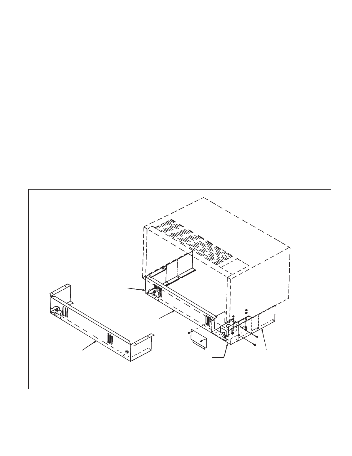
Chassis
Important: The chassis must be fully seated to provide a
proper weather seal. When properly installed, the front edge
will line up with the front edge of the cabinet/wall sleeve
1. Remove the chassis from the carton and check for
damage.
2. Compare the nameplate information to the job requirements and check the voltage supplied to the unit before
installing the chassis.
3. Remove all debris from the cabinet/wall sleeve and check
to see that the rear seal strip is securely attached.
4. Spin the condenser and room air fan wheels to make sure
they rotate freely, and they are tight. Check the copper
tubing in the compressor compartment. If required, bend
carefully to eliminate contact with other tubing or the
compressor shell.
5. Remove the two (2) hex nuts from the weld studs on the
cabinet and remove the two (2) clips.
6. Install the chassis in the wall sleeve. Check the seal where
the gasket on the discharge plenum seals against the
ange on the wall sleeve. The seal should be in complete
contact with the wall sleeve ange.
7. Attach the drain kit (if provided) or other suitable drain
provisions to the tting on the chassis. Required on
heat pumps only. See condensate drain kit installation
instructions.
10. Install the clips removed in Step #5.
11. Install the lter before operating the unit. If the optional
louvered front panel is furnished, install the lter in the
brackets on the back of the front panel and install the
bottom blockoff in the cabinet/wall sleeve.
12. If applicable, install Climate Director plenum system. See
Climate Director installation instructions.
13. Install the front panel before operating the unit. Fasten the
panel at the lower corners using the screws provided. See
front panel installation instructions.
14. See Figure 14 to check the weather seal.
Cleaning compounds can permanently damage unit. Do not spray
cleaning compounds onto the discharge grille, return air opening or
unit controls. Clean unit by wiping with a damp cloth. When using
cleaning compounds on carpets, oors or walls, turn the unit off
to avoid drawing vapors into the packaged terminal unit.
Figure 14: Perimeter Weather Seal
!
CAUTION
Cabinet/Wall Sleeve Weather Seal
8. Test drain operation by pouring approximately (2) quarts
of water into drain and assure proper removal.
9. Connect the main power, the control wiring (if furnished),
and the motorized valve wire harness (hydronic heat
model only).
Figure 15: Chassis Installation
Inside View (Rear
View of Wall Sleeve)
Note: Check the weather seal around the entire
perimeter for proper adhesion to the cabinet/wall sleeve.
IM 1079 / Page 10 of 24
Page 11

Front Panel
Install the front inlet blockoff as shown in Figure 16. Install
the front panel on the cabinet/wall sleeve by placing the
notches in the bottom of corners of the panel over the raised
tabs on the cabinet (see Figure 17). Place the ange on the top
inside of the panel in the slot on the cabinet and carefully push
down until the cabinet and the front panel align. The panel
may be secured in place by installing screws in each lower
corner.
Figure 16: Front Inlet Blockoff Installation
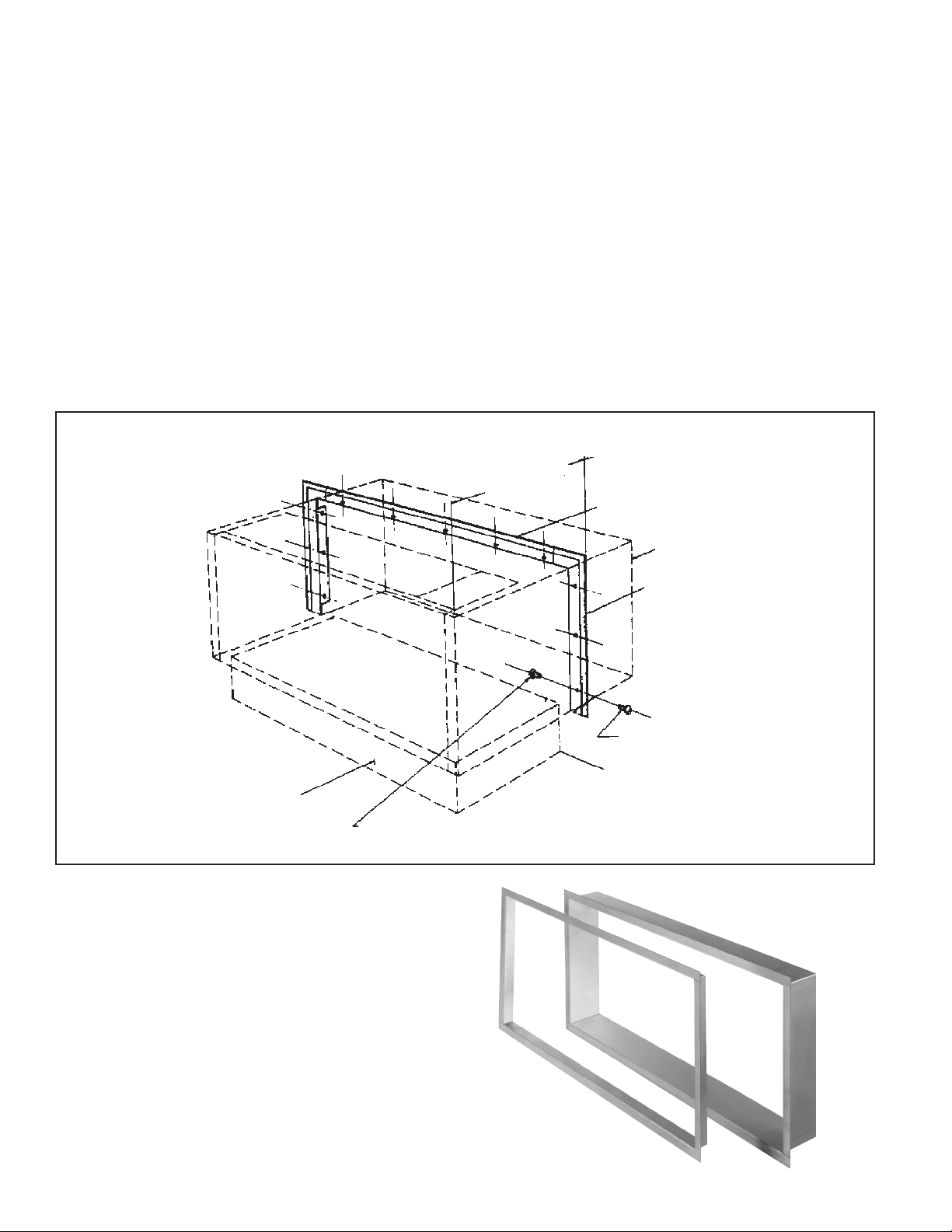
Climate Director Plenum
1. Visually inspect room cabinet/wall sleeve to ensure that it
was ordered and delivered without the standard grille and
access door.
2. For proper placement of the accessory discharge ple-
num, a minimum distance of 10½" (267mm) must exist
between the wall and the cabinet front panel.
3. Remove the discharge plenum from its carton and position
5/8" (16mm) from the front of the previously installed
room cabinet. Discharge plenum must not interfere with
removal of the front panel. See Figure 18.
4. Using the plenum as a template, mark the locations of the
four mounting holes in each corner. Remove the plenum
and drill holes in the top of the room cabinet for 1/4"
fastening bolts.
5. Replace the discharge plenum and fasten to the room
cabinet with the four (4)1/4" bolts and nuts provided.
6. Install end cap which clips into discharge plenum as
required.
7. Optional duct sections are shipped in two-piece “L”shaped sections. Pieces t together using a locking seam
method. Press pieces together to form a tight t.
Figure 17: Front Inlet Blockoff Detail
Figure 18: Climate Director Plenum and Duct Installation
Discharge Grille
Three grilles and three blockoffs provided with each plenum install blockoffs
at same end as duct
Discharge Plenum
Install with (4) 1/4" diameter
bolts and nuts provided with
plenum
Access Door
8. Attach 4-inch (102mm) or 3-foot (91.5cm) duct sections
to discharge plenum. Duct sections clip onto plenum.
9. A maximum of ve sections, 15 feet (4.56 meters), may
be used on one unit in a straight run only. No elbow
congurations of any type are acceptable. Sections may
be eld cut. Multiple sections must be supported every
3 feet (91.5cm) by the contractor. Multiple sections are
attached with a trim angle at the connecting seam. Attach
trim angle to both sections with the four (4) #8 x 3/8
screws provided.
10. Install grilles on ends of duct sections.
11. Install discharge grilles on discharge plenum. Three (3)
grilles and three (3) blockoffs are provided with each
plenum. Install blockoffs at same end as duct.
Optional Trim Angle
Use to attach two or more 3 ft. duct sections
together. Attach with (4) #8 x 3/8" screws
provided with trim angle
Note Position of Locking Seams
Note: Discharge Plenum Must Not Interfere
with Removal of Unit Front Panel
Optional 4" (102mm) Duct
May be installed at left end
or right end of plenum
Cabinet/Wall Sleeve
Unit Front Panel
End Cap Install Right or Left End
1/4" Diameter Bolt and Nut
IM 1079 / Page 11 of 24
Page 12

Unit Start-up
(Complete the, Check, Test and Start Form on page 13 and 14)
Figure 20: Subbases
Electrical Connections
The 37½" short cabinet is used for applications that utilize
electric resistance or reverse cycle/heat pump heating
technologies. The EnerSaver chassis power cord is designed
to plug directly into an electrical receptacle that is hard wired
and concealed within the subbase of the room cabinet/wall
sleeve (see Figure 19).
The 41½" long cabinet is used when the hydronic (hot water
or steam) heat option is chosen. Included with this room
cabinet is a junction box designed to house an electrical
receptacle that is hard wired to the facilities respective circuit.
In all cases, the electric receptacle is supplied by either the
factory or by others.
1. The electrical installation must be in accordance with
the job wiring diagram and comply with the National
Electrical Code and all local electrical codes.
Figure 19: Receptacle Location for Permanently
Connected Units
Receptacle
2. Permanently connected units may utilize time delay
fuses or HACR type circuit breakers (where applicable)
for branch circuit protection. Cord connected units may
utilize time delay fuses or circuit breakers for branch
circuit protection.
Standard 5" adjustable
depth Subbase
Short Cabinet Subbase
with Electrical Box
Condensate Drain
Test drain operation by pouring approximately (2) quarts of
water into drain and assure proper removal.
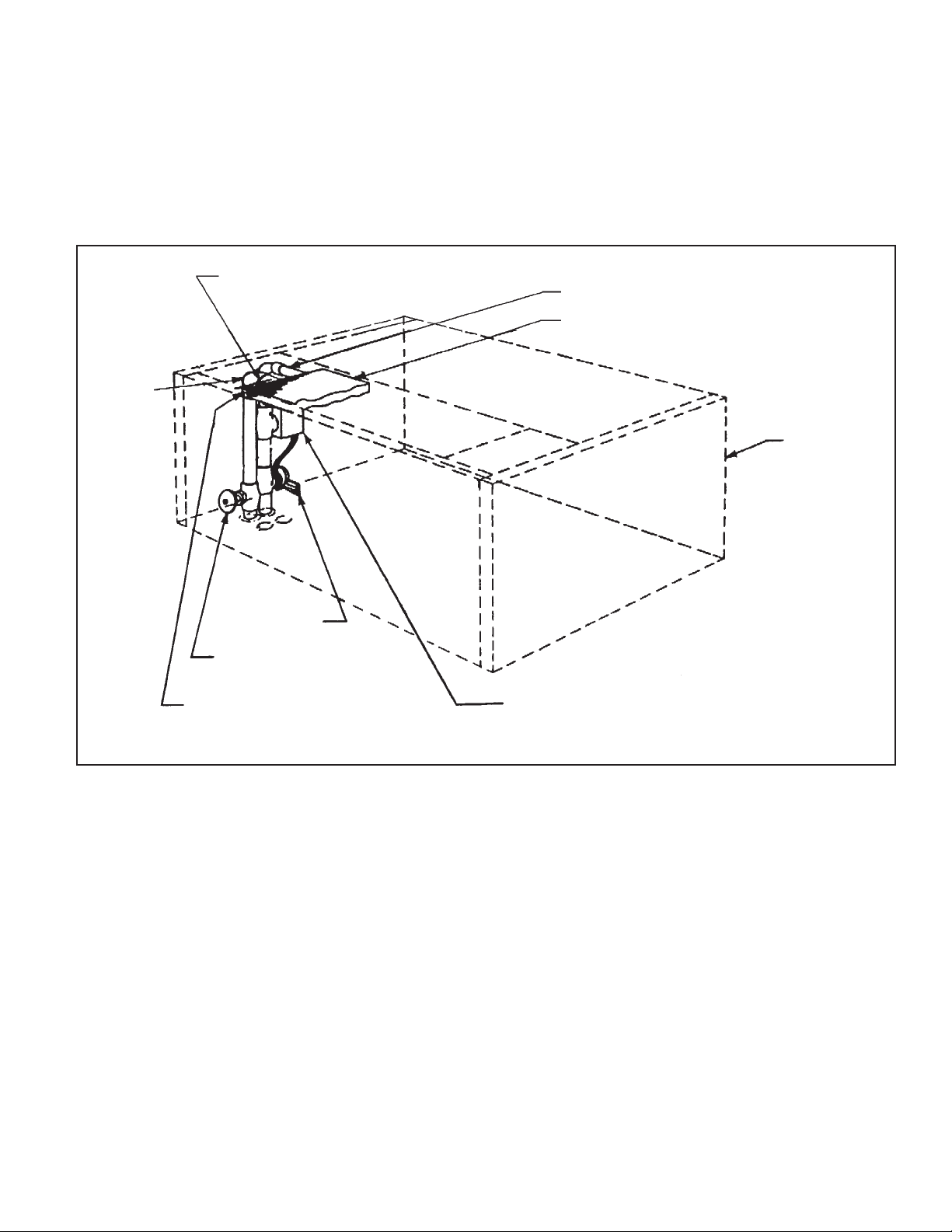
Outside Air Damper
Three outside air damper arrangements are available: a manual
damper, a motorized damper, and no damper.
The manual air damper is operated by removing the front
panel and then placing the lever in the desired position.
Pushing the lever opens the damper; pulling the lever closes it.
Units equipped with motorized air dampers are controlled by
removing the front panel and then placing the damper control
switch in the auto or closed position. The concealed switch on
the motorized damper is to help prevent unwanted tampering
with damper control. When this switch is in the auto position,
the damper will be open and remain open while the unit is on.
If the unit is turned off, the damper will automatically close.
Placing the damper control switch in the closed position will
keep the damper closed at all times.
Figure 21: Manual Outside Air Damper
3. Optional factory mounted circuit breakers, when fur-
nished, are not offered as branch protection.
4. Since all chassis have identical dimensions, regardless of
heating and cooling capacities, pay careful attention to
the branch circuit amperage requirement for each unit to
avoid electrical mismatching of chassis and permanently
connected branch circuits during eld installation.
5. Unit supply voltage must be as follows:
Nameplate Voltage
120V
208V
230V
277/265V
IM 1079 / Page 12 of 24
Minimum
108
187
207
249
Maximum
132
228
253
304
Figure 22: Motorized Damper
Page 13

McQuay International PTAC Check, Test & Start
Date Report — Audit
Job Name _________________________________________________ City ______________________ State ______________________
Installer ______________________________________________________________________________ Total No. of Units ___________
ISO#/GO#
Unit Type(s)
Date of Final CTS Start-up ____________________________________________________________
Manufacturers’ Representative Name ____________________________________________________
Suite II Type K
Type EA Type J
Enersaver
Other
ESSENTIAL ITEMS CHECK
A. Voltage Check __________________ Volts (measured)
B. Yes No Condition Yes No Condition
Filters Clean Operates in Heating
Evaporator Coils/Drain Pans Clean Operates in Cooling
Wall Boxes Sealed To Wall, No Leaks Operates in Fan Only (if so equipped)
Wall Box Pitch Satisfactory Hi-Lo Fan Speed Operational (if so equipped)
Chassis Installed Completely into Wall Box Fans Rotate Freely
Condensate Drains Installed Damper Working Properly (Manual or Automatic)
Air Discharge Free of Obstruction Test Drain Pan Operation
Note: “No” answers above require notice to installer by memorandum (attached copy).
Please include any suggestions or comments: ___________________________________________________________________________
________________________________________________________________________________________________________________
________________________________________________________________________________________________________________
________________________________________________________________________________________________________________
________________________________________________________________________________________________________________
Above System is in Proper Working Order FOR INTERNAL USE
Release:
________________________________________ SM _______________________
CTS_______________________
Date
T _________________________
Note: This form must be completed and returned to the Warranty Adminis-
Signature for Sales Representative
Signautre for Customer
Service Manger Approval
trator before any CTS, rst year monies can be released for payment. Failure to complete this form may cause unnecessary interruption in job site warranty.
Date
FORM No. PT-CTS-1206
IM 1079 / Page 13 of 24
Page 14

PTAC Check, Test and Start Worksheet
(For additional units copy this page) Page _____ of ___________
Cooling Heating Damper Amp
1.
2.
3.
4.
5.
6.
7.
8.
9.
10
11.
12.
13.
14.
15.
16.
17.
18.
19.
20.
21.
22.
23.
24.
25.
26.
27.
28.
29.
30.
31.
32.
33.
34.
35.
36.
37.
38.
39.
40.
41.
42.
Model Serial # Room # Installation OK
Check
Check
Working
High Fan Low Fan
Check
IM 1079 / Page 14 of 24
Page 15

Unit Maintenance and Operation
With today’s high energy and labor rates, a sound preventive
maintenance policy is a very good investment. Clogged
and restricted air lters and coils can impede the ow of air
through the unit and can cause inefcient operation. Such
conditions only increase operating costs.
Poorly maintained equipment is an open invitation to short
unit life and frequent repair charges.
Filters — EnerSaver units are available with either a permanent lter or a disposable charcoal lter. Clean lters are
essential to proper airow through the unit. Utilities are
currently recommending lter inspection and replacement at
least once per month.
Vacuum permanent lters to remove loose dust. Then wash
the lter in a warm, mild soap solution to remove trapped
material. Rinse the lter and allow it to dry. Do not operate the
unit without both the lter and the unit front panel in place.
Evaporator Fan Motor — All Fan Motors are permanently
lubricated by the manufacturer. They do not require further
oiling.
Gaskets and Seals — It is extremely important that all
gaskets and seals be in place and intact. A loose or missing
gasket will prevent correct seating of the chassis in the
cabinet/wall sleeve, allowing inltration of outside air and
water into the room space. See Figure 24 for gasket and seal
location and arrangement.
Figure 24: Gasket and Seal Location
Seals
Removing Chassis — It is not necessary to remove the
chassis to perform most of the general maintenance proce-
dures just outlined. However, if the chassis requires removal,
use the following procedure:
1. Remove front panel by lifting upward from bottom.
Condenser Fan Motor — All Fan Motors are permanently
lubricated by the manufacturer. They do not require further
oiling.
Coil Surfaces — Clean coil surfaces are essential to efcient
heat transfer. A dirty coil can severely impede the operation of
a unit.
Visually inspect and clean the condenser and evaporator coil
surfaces annually. Inspect and vacuum the hydronic heating
coils before the beginning of each heating season.
Condensate Removal System — Condensate forms on
the evaporator coil during normal operation of the unit. An
internal system is provided to dispose of this condensate. It
is necessary to keep the drain pan and condensate line
clean to keep the system functioning correctly. Cleaning
the condensate pan is most convenient when it is done at the
same time as the annual coil inspection. See Figure 23 for the
location and removal of the drain pan and line.
Figure 23: Evaporator Drain Pan Cover Removal
2. Disconnect power to the unit by unplugging the control
box power cord from the unit receptacle/junction box (or
room receptacle on cord-connected units).
3. For units with remote controls, disconnect low voltage
lines connecting the control box with the wall thermostat.
4. For hydronic heating units, disconnect the motorized
valve from the control circuit. To do so, disconnect the
plastic connector at the left side of the chassis.
5. Remove chassis support brackets.
6. For PTHP units, disconnect the condensate drain kit rubber tube from the chassis drain connection.
7. After all wiring has been disconnected, place ngertips
under chassis removal ange and slowly pull chassis out
of the cabinet/wall sleeve. See Figure 25. Take care not
to allow the back of the chassis to “fall out” of the sleeve.
Damage can result if this happens. Some drain pans can
contain a small amount of water. Take care (i.e., drop
cloth, etc.) to prevent spills from staining carpet or oors.
Figure 25: Chassis Removal Flange
IM 1079 / Page 15 of 24
Page 16

Specic Operating Conditions
Familiarity with the correct operation of the units will allow
you to spot potential problems before they become serious. The
following list details specic operating conditions which you
should be aware of to help identify a unit malfunction.
1. Units with low ambient lockout should not operate on
cooling below 40°F (4°C) outside air temperature.
2. Frequent cycling of the compressor can reduce life expectancy of your unit. This could be caused by an over-
sized unit, poor location of the wall thermostat (when
used), low supply voltage to the unit, low refrigerant
charge, or outside air inltration.
3. Compressor failures are sometimes related to condenser
fan motor failures. If the condenser fan motor fails, the
4. Operating the units during low voltage periods can
damage the unit. If a brownout occurs, or local utilities
warn of voltage cutbacks, it is best to turn off the units.
The compressor is protected against voltage variations
and phase loss to the extent covered by U.L. Standard 484
for Room Air Conditioners.
5. Keep the discharge and return air grilles clean and
unobstructed. Do not use the cabinet/wall sleeve as a shelf
or table, since this restricts the ow of air from the unit.
6. During building construction periods, units should not be
used as temporary heating or cooling sources.
7. Remove any paper and other foreign material from the
unit before operating it.
compressor will continue to run and will operate at high
head pressures and temperatures which will eventually
cause the compressor to fail. To help prevent this, check
8. Test drain operation by pouring approximately (2) quarts
of water into drain and assure proper removal.
for proper operation of the condenser fan motor whenever
routine maintenance is scheduled.
Typical Schematics
Figure 26: Enersaver PNES with Unit-Mounted Thermostat, Electric Heat, No Setback, Manual Changeover
Note: See page 17 for schematic Legend.
IM 1079 / Page 16 of 24
Outdoor Air Motor Wires
Unit Size Color
009B (208) RED
009B (230/265) BLK
012B-015B
(208/230)
012B-015B (265) BLK
Room Air Motor Wires
Unit Size Hi Lo
009B (120/265) BLK RED
009B (208) BLK BLU
009B (230) ORG RED
012B (208/265) BLK BLU/RED
015B BLK BLU
RED/BLK
Page 17

Figure 27: Enersaver PNHS with Unit-Mounted Thermostat, Electric Heat, No Setback, Manual Changeover
Legend
Field Connection
Option Wire
Field Wire
Quick Connect
C1/3 Capacitor
CB Circuit Breaker (Option) (120/265V-1 Pole) (208/230V-2 Pole)
HL Hi Limit
HTR Electric Heater
M1 Motor-Room Air
M2 Compressor
M3 Motor-Outdoor Air Fan
M4 Motor-Vent (Option)
OL Compressor Overload
P1 Plug-Chassis
P2 Plug-Low Voltage
Wire Nut
HP High Pressure Cutout
P5 Plug-HP Cutout
R7 Relay-HP Cutout
Outdoor Air Motor Wires
Unit Size Color
009B (208) RED
009B (230/265) BLK
012B-015B (265) BLK
Unit Size Hi Lo
009B (120/265) BLK RED
009B (208) BLK BLU
009B (230) ORG RED
012B (208/265) BLK BLU/RED
015B BLK BLU
R2 Relay-Cooling
R3 Relay-Heating
R4 Relay-Fan
R5 Relay-Setback
R6 Relay-Interlock
RV Valve-Reversing
S1 Switch-Push Button
S2 Switch-Damper
T Transformer-Class 2
TB1 Terminal Block
TC1 Thermostat-Room Air
TC2 Thermostat-Setback
DOB Relay-DOB
TC4 Thermostat-Low Limit
TC5 Thermostat-Freeze
TD2 Relay-Time Delay
TC3 Thermostat-Low Ambient Lockout
TD1 Relay-Remote Setback (Option)
TB3 Terminal Block
012B-015B
(208/230)
RED/BLK
Room Air Motor Wires
IM 1079 / Page 17 of 24
Page 18

Wall Thermostat Adjustment
The wall thermostats used on EnerSaver units have a built-in
anticipator. In order to obtain even, comfortable heating in a
conditioned space, it is absolutely essential that the thermostat
anticipator is properly adjusted.
The anticipator is a small, adjustable resistor through which
the low voltage control current passes. On heating demand, the
thermostat closes and the unit operates on heating; the anticipator
heats up, giving the thermostat a false signal. If the thermostat
has to wait for the heat from the heating unit to reach it, the room
would have a tendency to overheat. The anticipator prevents
this by raising the temperature at the thermostat and stopping
the unit early.
There are two ways to set the anticipator. Take the control circuit
current draw, if it is known, and adjust the anticipator to this
value. This method will work satisfactorily in the majority of
cases. If the control wiring is oversized, the control voltage low,
or additional components are operated from the control circuit,
then the anticipator must be calibrated for each thermostat.
Remove the thermostat exposing the subbase, connect an ammeter
between the hot 24 volt terminals and the heating lead terminal.
The ammeter should be capable of reading accurately from 0.1
to 4.0 ampere. Record the value and adjust the anticipator to the
value recorded.
Typical recommended thermostat heat anticipator settings are
shown in the table below.
AC Retrot with HP Chassis
EnerSaver Heat Pump units are an excellent replacement for
Air Conditioning units. The chassis dimensions are identical,
allowing the H/P chassis to t into the A/C wall sleeve. The
major addition required is that of a condensate removal system.
On single-story applications, the condensate drain line may be
routed through the rear of the cabinet/wall sleeve allowing the
line to project out of the unit. Caulking around this notch will
prevent entrance of water into the sleeve. Multistory buildings
should utilize a more sophisticated condensate removal system
to prevent excessive drainage down exterior walls.
Note: Check cabinet/wall sleeve level of installation. For
condensate to drain properly, the sleeve must be set and
leveled from side to side. Then level the unit front to back
with no more than 1° slope downward toward the outside.
A nal consideration when retrotting an A/C wall sleeve
with an H/P chassis is branch circuit ampacity. The units
must be the same voltage, and have an ampacity equal
to or less than the A/C unit it is replacing.
Unit Type Anticipator Settings
Cooling Heat — Wet Heat — All Voltages .13
Cooling Heat — Electric Heat — All Voltages .15
Heat Pump — All Unit Types & Voltages .37
The anticipator should now be properly adjusted and very little
uctuation in room temperature should be noticed. The room
should be allowed to stabilize for 48 hours before checking the
effect of the anticipator adjustment. If complaints are still received,
small readjustments may be required due to the conguration
of the space.
The adjustment of the anticipator is a eld adjustment which
must be made by the installing contractor. In all cases, when
there are complaints of uneven heating in a space, ensure that all
anticipators are properly set. Optimum performance and comfort
cannot be expected unless anticipators are set correctly.
IM 1079 / Page 18 of 24
Page 19

Troubleshooting
The following troubleshooting guide should aid in detecting
unit malfunctions.
!
WARNING
Troubleshooting can present risks of equipment damage, severe
personal injury or death. Troubleshooting must be done by trained
experienced technicians only.
Complaint Probable Cause
Entire unit does not
operate.
Electric shock from
equipment.
Evaporator blower
assembly operates,
but is noisy.
Evaporator blower
assembly operates,
but compressor does
not start.
1. Power failure.
2. Push button.
1. Improper grounding of electric circuit.
1. Motor mounts.
2. Fan wheel.
3. Motor bearings.
1. Power.
2. Unit mounted manual change over thermostat.
3. Unit mounted automatic change over thermostat.
4. Wall mounted manual change over thermostat.
5. Wall mounted automatic change over thermostat.
6. Unit control panel.
7. Low ambient lockout.
8. Run capacitor defective.
9. Stuck compressor.
Checks and Corrections
1. Check for blown fuses or tripped circuit breaker. Check fuse sizes. Check
wiring connections and check for both high and low voltage.
2. Check for push button operation. Check for loose terminals, broken wires,
or defective push button. Replace if necessary.
1. Provide proper ground. Check for short circuits.
1. Check motor mounts; they might be loose. If so tighten. They could have
become bent in transit. Reposition and retighten.
2.
Check for proper alignment in fan housing. Check for tightness on motor
shaft. Check for foreign material in fan wheel or housing; e.g., construction debris, paper, plaster. Clean and retest. Check the electrical exible
conduit; it may be rubbing against fan assembly or unit front panel.
3. Check motor bearings. Replace if necessary.
1. Check for proper voltage at compressor terminals. See page 12 for compressor voltage range. At the power source check for proper wire size.
2. Turn unit temperature control knob to normal. Then push “High Speed”
button and push “Cool” button. The unit should turn on. If not, move the
thermostat knob clockwise to the end of its travel. If no contact is made,
hold thermostat bulb rmly in hand for a few minutes. If no reaction, check
wiring and continuity at terminals 1 and 2 at back of thermostat. If open
circuit when bulb is warm, remove and replace thermostat.
3. Turn unit temperature control knob as above. Press “High” or “Low” button.
The unit should turn on provided the setting on the thermostat is lower than
actual room temperature. If not, move thermostat setting to the coldest
point; it no contact, hold thermostat bulb rmly in hand for a few minutes.
If no reaction, check wiring and continuity at terminals 4 and 5 on back of
thermostat, If no continuity, remove and replace.
4. Set unit on “High” or “Low” speed push button. Then push on cool switch
on wall stat. Turn temperature lower than actual room temperature. Cooling relay should energize and compressor should start. If cooling relay
is chattering or humming, check for 24 volts supply at relay (should not
be lower than 18 volts). Caution should be exercised in the length of the
24V wire run from the unit to the stat. If run is excessive for gauge of wire
used, there may be a natural voltage drop. If compressor not running,
place jumper wire at subbase between terminal “Y” and “R”. If no voltage
at relay, check wiring at transformer.
5. Make sure jumper wire between RH and RC (On subbase) has been eld
wired. Set unit on “High” or “Low” speed. Then move lever (cooling) at
thermostat to temperature lower than actual room temperature. Cooling
relay should become energized. If compressor is not running, check for
wiring at transformer.
6. On unit using 24 volt transformer, check for low voltage open circuit;
check 24 volt transformer for burnout, check contacts (relays may be dirty
or binding); check for loose wires if below 18 volts. Caution should be
exercised in the length of the 24V wire run from the unit to the stat. If run
is excessive for gauge of wire used, there may be a natural voltage drop.
Disconnect and replace providing the primary voltage is within specied
limit (10%). Check for loose terminals or connections. They will change
color indicating the presence of heat. If so, change terminal.
7. If outside temperature at time of complaint was below 40OF (4OC), unit was
probably okay but was locked out on low ambient protection. If not, apply
heat by palm of hand to lock out control and warm up to a minimum of
60OF (16OC). and check for continuity. If open, remove and replace.
8. Check for overvoltage and light load. Reduce line voltage to value given
on page 12. In general, voltage should not exceed 10% over and above
nameplate voltage, If capacitor is suspected to be defective, test it with an
ohmmeter Check for water dripping over terminal, or for terminals shorting
together causing a dead short, If water dripping is suspected, nd traces
of water or condensation and make correction.
9. Before attempting this next checkout, ensure that the run capacitor is
not defective. Try an auxiliary capacitor momentarily, If the compressor
starts but the problem reoccurs on starting, install an auxiliary hard start
kit (referred to as PTC, Positive Temperature Coefcient Resistor) and a
correctly sized capacitor.
IM 1079 / Page 19 of 24
Page 20

Complaint
Evaporator blower
assembly operates, but
compressor does not start
(cont’d).
Compressor starts, but
does not switch “off” start
winding.
Unit short cycling.
Unit is running, but no air
is being delivered to room.
Insufcient cooling.
Too much cooling.
Evaporator blower
operates, but no heating
(electric heat).
Probable Cause
10. Compress or motor grou nded or has an
open winding.
1. Improperly wired.
2. Low line voltage.
1. Thermostat.
2. Wiring.
3. Control contacts uttering.
4. High amperage draw.
5. Refrigerant overcharge.
6. Compressor runs hot and cuts on overload
protection.
1. Evaporator airow restricted.
2. Evaporator coil iced up.
1. Evaporator airow restricted.
2. Automatic expansion not functioning properly.
3. Compressor efciency down.
4. Outside air entering room.
5. Unit too small.
1. Thermostat set low.
2. Defective thermostat.
1. Power at heating element.
2. Overheat switch.
Checks and Corrections
10. If the compressor temperature is above 130OF (54OC) the internal overloads
may not have reset yet. Allow the compressor to cool down before checking
the unit again (compressors cool slowly so cooling may take over an hour). If
the compressor is cool and does not start, test the motor windings. Remove the
electrical connections from the compressor and measure the resistance across
the Run and Start windings and/or the Start winding alone. If no resistance is
read, the windings are open and the compressor should be replaced.
1. Check against wiring diagram and correct if incorrectly wired.
2. Check voltage at compressor. Place voltmeter leads at common and run
terminals. Start compressor, read voltage. If below tolerance, check electrical
installation for proper sizing of wires and length of run of wiring for extreme
voltage drop.
1. If remote wall mounted thermostat check for proper heat anticipator setting as
described on page 16.
2. Check for loose terminal or connections in the electrical circuit. Trace and
repair.
3. Check control contact points. If pitted or corroded, remove and replace. Do not
le or clean with abrasive material.
4. Check compressor amperage draw at full load condition. If abnormally high
amperage, check condenser fan operation; fan should always be on when
compressor is running. Also check for refrigerant overcharge as outlined in
the next procedure.
5. Since there is no access valve to the refrigeration circuit, the “Frost Back”
method can be used, described as follows. While compressor is running,
observe the suction line from evaporator to compressor shell. If heavy frost
appears on the line, there is a possibility of an overcharge. To correct, use a
piercing valve on compressors processing tube and bleed off refrigerant slowly
until the frost line backs up 3" or 4" (76mm or 102mm) from compressor shell.
Caution: This method of checking the refrigerant charge is acceptable for this
situation. It is not acceptable for recharging a unit, in which case the amount
charged must be determined by either a graduated charging cylinder or by
weighing.
6. Check condenser coil in back of chassis. If there is excessive buildup of dirt,
clean the coil. Check for condenser fan. Also, either a high amp draw condition
(as described above) or this condition can be caused by short circuiting of the
condenser discharge air into the inlet airstream.
1. Dirty lter; change or clean. Obstruction in unit; remove. Dirty evaporator coil;
clean.
2. Check evaporator fan. If running, check expansion valve operation. If okay for
rst row of tubes at evaporator coil but frozen on remaining rows, clear off frost
and measure actual superheat 3 or 4 inches away from compressor ’s shell (on
suction line). If superheat exceeds +20OF (+11OC), low charge can be suspected
and unit should be evacuated and recharged by weight to nameplate data.
1. Dirty lter; change or clean. Obstruction in unit: remove. Dirty evaporator coil;
clean. Evaporator fan motor not up to adequate speed; fan wheel slipping on
shaft; tighten setscrews.
2. Check suction and/or proper opening at right pressure. Wrap expansion valve
with hot damp cloth, If pressure is restored by this method, then there is indication of moisture in the refrigeration circuit. Discharge refrigerant. Dehydrate
system with a deep vacuum pump and recharge according to procedure. If any
indication of moisture in system or a burn out, a lter-drier should be installed,
If problem still exists, remove expansion device and replace with new one.
3. Check for warm suction (high superheat) and slightly warm discharge. Check
actual temperature and pressure. If discharge pressure low and suction pressure high, may be compressor. Check with factory for procedure.
4. Check for open doors, windows or other openings and improper unit caulking.
5. Recheck heat gain, add additional insulation, shading, etc., or add additional
units.
1. Turn to higher setting.
2. Replace.
1. Check for proper voltage at heating element. Check for broken wires or loose
terminals at element, If broken, do not try to repair. Remove and replace complete element.
2. Overheat switch could be defective. Check continuity through switch when
switch is cooled down to approximately 235OF (113OC) and lower, it should
show continuity and should be open circuit at approximately 260OF (127OC)
IM 1079 / Page 20 of 24
Page 21

Complaint
Evaporator blower operates,
but no heating (electric heat)
(cont’d).
Evaporator blower operates,
but no heating (hot water or
steam).
Unit operates on cooling, but
water is dripping from unit.
El ec tr ic he ating el em en t
operates, but room side fan
does not operate.
PT HP uni t only pr ovide s
heating (no cooling).
PTHP unit not heating below
4OOF (4OC) outdoor ambient.
PT HP rev ers ing val ve no t
shifting from cool to heat or
heat to cool.
PTHP reversing valve starts to
shift, but does not complete
reversal.
Noisy operation.
Probable Cause Checks and Corrections
3. Push button device.
4. Thermostat.
1. Hot water valve or steam valve.
1. Chassis not properly installed in wall sleeve.
2. Condensate hose obstructed.
3. Evaporator drain pan not draining.
4. Air bypass at top of unit.
1. Motor capacity.
2. Loose terminals or broken wire.
3. Push button.
4. Defective motor.
1. Reversing valve not energizing.
2. Defective thermostat.
1. Fault low temperature at stat.
2. Check auxiliary heat.
1. Electric circuit: low solenoid coil voltage.
2. Refrigerant charge: low charge.
3. Defective compressor.
1. Insufcient pressure or both ports of pilot open.
1. Evaporator fan motor bearings.
3. Check contacts through push button (selector switch). If no contact
after switch has been pushed, check for loose wires or loose terminals, If
all connections okay but still does not operate, remove push button switch
and replace.
4. Move thermostat knob to highest setting. If unit still does not heat, check
through thermostat contacts. If no continuity when above set point, remove
and replace thermostat.
1. Check for proper water or steam circulating valve. Check water temperature. Check for continuity across valve motor. If defective, remove and
replace.
1. Cabinet should be set level side to side and level to no more than 1° slope
downward toward outside, front to back. If not, reinstall wall sleeve. Check
for proper gasketing between wall sleeve and chassis. Check that chassis
rmly installed in sleeve so that gasketing on discharge is compressed.
2. Check for dirt and foreign material in condensate hose running from
evaporator drain pan to exterior pan in condensing section.
3. Make sure access cover on drain pan is well placed on top of drain pan.
If not, press rmly into position. If okay, check and clean drain pan and
drain hole.
4. Check for proper chassis installation in wall sleeve. Make sure that gasket around air discharge on chassis is well pressed against top of wall
sleeve, and chassis support clips are in place. This will prevent cold air
from evaporator cabinet outlet to hit the back of cabinet front panel, thus
creating condensation.
1. Test capacitor with an ohmmeter; replace if necessary.
2. Check for loose connection or broken wire. Refer to page 14.
3. Check for continuity when push button is pressed. If defective, replace.
4. Check for continuity or ground at motor. If so, remove and replace.
1. Faulty solenoid or loose wiring at solenoid terminals.
2. Replace thermostat.
1. Replace.
2. See electric, hot water or steam heat procedures above.
1. Check voltage at solenoid with voltmeter. Replace if necessary.
2. Check for leaks. Recharge system.
3. Replace.
1. Check unit operating pressure and charge. Raise head pressure, operate
solenoid. If not shift, replace valve.
1. Check motor bearings. If loose or damaged, replace complete motor.
2. Evaporator fan wheel hitting fan housing.
3. Loose blower wheel.
4. Copper tube vibration or rattling.
5. Contacts.
6. Compressor internal mounts distorted.
7. Compressor internal damage.
8. Liquid refrigerant in compressor crankcase.
2. Relocate wheel in center of blower housing. Check for bent motor shaft.
3. Tighten setscrews on blower wheel to shaft.
4. Adjust by bending slightly to rm position.
5. Contactor noise would be due to control voltage being less than 18 volts.
Check for low voltage supply, low transformer output or extra long runs of
thermostat wires. If the contactor contacts are pitted or corroded, replace
contactor. Never le contacts. If holding coil is defective, replace.
6. Often referred to as “compressor off mounting springs", which in most
cases is highly improbable. If unit was rough handled in transit the internal
mounts might have been distorted and compressor main casting is touching
the dome or shell.
7. Make sure the compressor is not in direct contact with the base or sides of
chassis. The compressor should oat free in its isolation mounts. Excessive noise will occur it the compressor has a broken valve or loose internal
discharge tube. If so, replace compressor.
8. After a prolonged period of non-operation, compressor might produce
abnormal noise on start-up. This could be due to liquid refrigerant being
mixed with oil in compressor crankcase. After a short delay this noise
should disappear.
IM 1079 / Page 21 of 24
Page 22

IM 1079 / Page 22 of 24
Page 23

IM 1079 / Page 23 of 24
Page 24

Warranty
All McQuay equipment is sold pursuant to its standard terms and conditions of sale, including Limited Product Warranty. Consult your local McQuay Representative for warranty details. Refer to Form
933-43285Y. To find your local McQuay Representative, go to www.mcquay.com.
This document contains the most current product information as of this printing. For the most up-to-date
product information, please go to www.mcquay.com.
Products Manufactured in an ISO Certified Facility.
© 2010 McQuay International • www.mcquay.com • (800) 432-1342 IM 1079 (7/10)
 Loading...