

Page 1

Installation Instructions For
CENTRIFUGAL WATER CHILLERS
LESS CONDENSERS
Models
13600 Industrial Park Blvd., P 0. Box 1551,
PLH
046,
079,
Minneapolis
048,
087,
MN 55440
050,
100
063
Page 2

Page 3
Page 4

GENERAL
The less condenser chiller unit is partially factory assembled, wired and checked. Installation (by others) will require piping, power, and control interlock connections to the
machine. Factory mounted and wired compressor motor
starters are available as an optional accessory. All units are
shipped with a holding charge of refrigerant.
All rigging, installation, power and control wiring and refrigerant piping are the responsibility of the installer. Recommendations for the installation of the less condenser unit are provided in the paragraphs following.
IMPORTANT: The responsibility and/or duties of the
installer and McQuay at the time of startup are detailed in the startup section on page 11. It is important
that the installer be aware of the limits of this responsibility since McQuay startup services beyond these
limits will only be performed after written authorization
has been obtained from the owner and/or installer.
Do not under any circumstance make final power
connections to the unit mounted starter (when supplied)
or to the compressor terminals when a remote starter
is used. The compressor cannot be put in operation until the the McQuay service technician has checked the
unit installation and electrical phase sequence for proper compressor rotation.
McQuay equipment when applied to perform the duty for
which it has been designed, and when it is operated within
limits of the design specifications, will provide safe and dependable service.
CAUTION
DO NOT ABUSE THE EQUIPMENT.
MODEL NOMENCLATURE
PLH -
0635 - AE - 30R I E2212 - GB - 2RA
Nomenclature Change: The 2-letter model code
new code for PE chillers less condenser
IO12
(“L”
at the end of
“PL”
is a
the old model number signified less condenser). The letter
“H”
has been added behind the first two digits of the model
code to signify a hermetic compressor motor. Model PLH is
synonymous with model PE-L.
UNIT NAMEPLATE
Whenever requesting information or assistance on the model
PLH water chilling unit, the unit model number, shop order
number and serial number should be copied from the unit
nameplate. A reproduction of this nameplate is shown in
Figure 3.
Figure 3. Unit Nameplate
Do not step on any piping or climb over the machine.
Do not exceed test pressures. Be sure to verify
allowable test pressure for the McQuay unit and
other items in the piping system.
Be sure all pressure relief devices are correctly installed. When vent piping to the outside is utilized,
be sure piping has a flexible connection and a drain
to prevent buildup of rain water or condensate. See
Figure 7.
Do not use oxygen to purge or apply pressure to a
unit or system for any reason.
RECEIVING THE EQUIPMENT
1. CHECK EQUIPMENT before removing it from the ship-
ping vehicle. The unit nameplate contains the unit model
number, serial number, etc. Figure 3 indicates the infor-
mation
contained on the nameplate. Check the nameplate
data against shipping papers and job information. Pay
careful attention to voltage characteristics. (Check voltage
on compressor nameplate.)
HOLDING
CHARGE
ONLY
MODEL
STYLE
SERIAL
S.O. NO.
\
I
PLH~J
1
PE5210-GO1
5NAl23~500 ~~
PE-5210
FACTORY CHARGED
_
LBS. REFRIGERANT=
LEAK TEST PRESSURE
MOTOR - COMPRESSOR CONTROLLER
AND OVERLOAD PROTECTION FIELD
SUPPLIED. SEE SPEC. PE-D4
19SP1Wi01-A MADE IN U.S.A.
100 PSIG.
2. INSPECT the unit while it is still on the shipping vehicle,
record any damage and note whether or not unit has been
torn from the shipping skid. In the event that the unit has
lost the refrigerant holding charge, look for damage to
refrigerant lines and connections. See testing and
evacuation section on page 9. Have all damage checked by the
transportation inspector or their representative before
Page 4
/
IM 310
Page 5

removing the unit from the vehicle. Promptly forward claim
forms directly to the carrier. Notify the nearest McQuay
sales office or representative of any item missing from the
shipment.
NOTE: All equipment furnished by McQuay is
shipped F.O.B. factory and all claims for handling
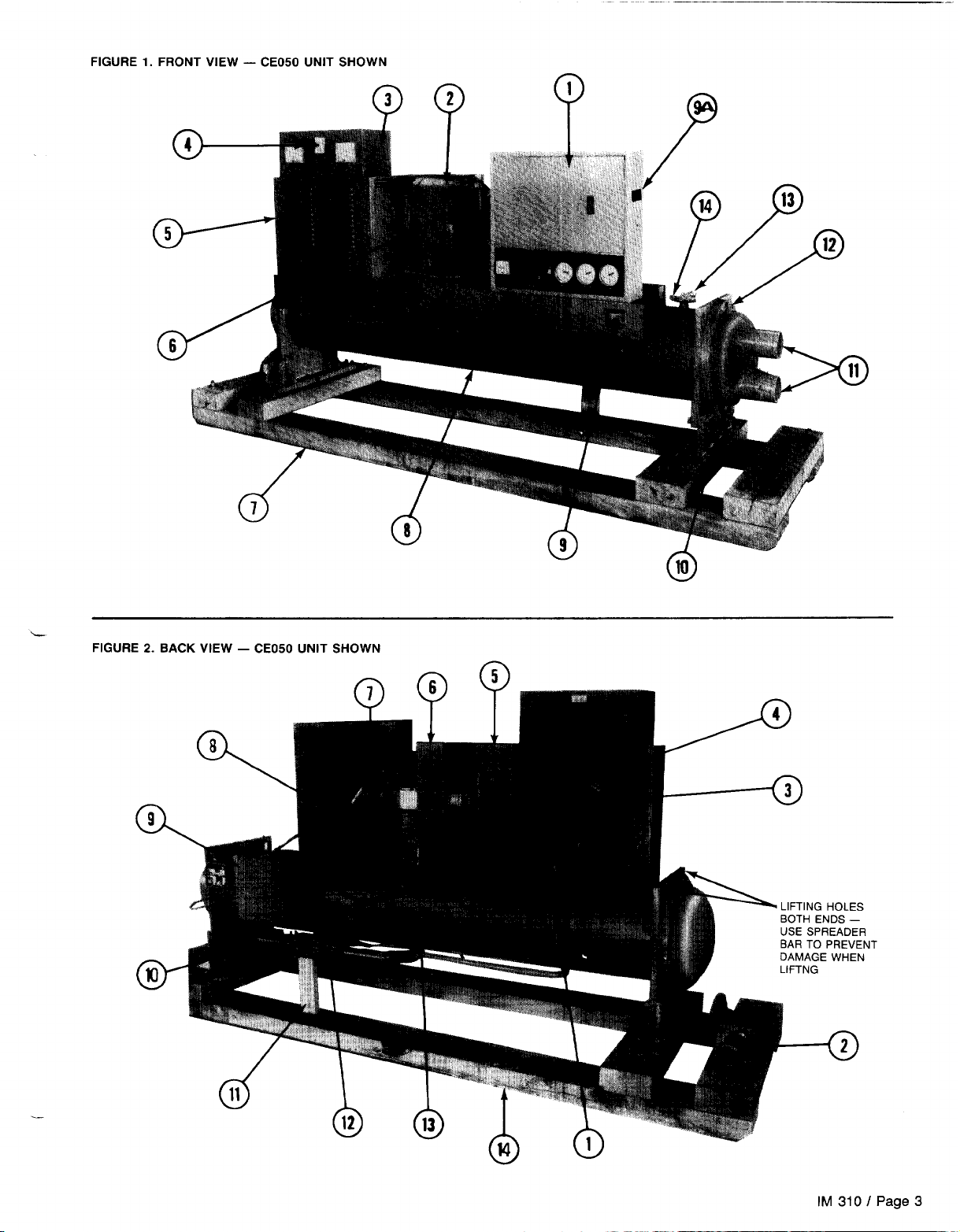
3. RIGGING. Lift unit only from points indicated in Figure 2.
Where required, use a spreader bar to prevent damage
to the unit. Be sure rigging equipment and procedures
INSTALLATION
followed are adequate to handle the unit weight. When
skidding the unit, be sure a minimum of 3 rollers are
used. Under no circumstances should the unit be
dragged with or without the skid.
PROTECTION. The unit assembly and starter (where
separate) must be adequately protected against dirt,
moisture and freezing during construction.
Chillers are drained of water before leaving the factory.
The chiller is not self-draining and must be blown out to
remove water if water has been added at the jobsite. When
the unit will be exposed to low temperatures during construction, a small amount of antifreeze should be put in
the chiller to protect it from freezing.
1.
CLEARANCES. A clearance for chiller tube removal at one
end of the unit must be provided. This clearance is
for shells with
1
2-foot
tubes. For all other unit sides and top, a clearance
8-foot
tubes and 14 feet for shells with
10 feet
of 3 feet is required.
2. UNIT SUPPORT. The floor or structural support must be
level and adequate to handle the full operating weight of
the unit. Operating weights for units are shown in Table
3. VIBRATION ISOLATION
a. “lsomode” or “Shearflex” pads are supplied with the
unit for installation under each corner of the
Unit
base
members.
It is not normally necessary to attach the unit to the
concrete slab or framework, but should this be
desirable,
1%” diameter holes are provided as shown
on the submittal drawings for the unit.
Figure
4. Typical Installation of Standard Isolation
UNIT TUBE
SHEET SUPPORT
r
ISOMODE
FURNISHED
WITH
PAD
“NIT
Note: Pads are shipped stored
in the switch section
of the control center.
Spring Isolators supplied by others may be placed
b.
under base support plates on both ends of the unit. Job
information should contain details on type and arrangement. Figure 5 shows a typical installation of spring
isolators. Spring isolation is not generally required but
1.
may be necessary if the unit is installed on the upper
floor of a building.
Table 1. Rigging 81 Operating Weights (Less Condenser)
(For weights of other
EYmtm
OODE
combinations,
RfQKOIWQ
WT.
(MS.)
cp
see certified drawings)
OPERATtAKS
WT.
OD
(LB%)
luooeLI tI4@, 048, oao
El 606-A’
-0’
E2006-1
l
-2’
E2012-C’
E2212-G’
E1612.1
I
I
-D’
-E’
-J’
I
2102
2203
2637
2726
3060
3262
3416
3533
3633
McBaEL
3399
I
I
033
I
2616
2697
3401
3470
4210
4372
4566
4665
5145
4088
LEVEL SUPPORT
BASE
Figure 5. Typical Installation of Spring Isolators
llN,T
BASE
ATTACH SECURELY
TO VIBRATION
\
LEVEL FLOOR
OR SUPPORT NEOPRENE PAD
SUPPORl
-4 4426
E2016-1
-2
-3 4959
-4 5065
E2212-1
-2 4536
-3 4637
E2216-1
-2
-3
-4 6823
r&m% m
MOlM&tia7..‘.....,.
f#%@kL
%
Rigging Weight: Unit Weight + Holding Charge of Refrigerant
0
Operating Weight: Rigging Weight + Water Weight + Operating Charge
of Refrigerant
. . . . . . . . .
toO .
. . . . . I. .
4619
4671
4457
4894
6539
6665
Add
35s Fb8.
to
Add
11@6 Lb. to osl)
*
Add
1972 Lbs. to 003
063 Evaporator WsiQhts
Evaporator Weights
Evaporator
5450
5915
6167
6255
6381
5675
5756
5655
6334
9103
9229
9387
WelaMs
IM 310 I Page 5
Page 6

PIPING
General - Chiller water and refrigerant piping connections
to the unit are required and good piping practice must be
followed during installation. All piping should be installed per
specific job piping drawings and details covered by these
drawings. In addition, the details and provisions following
below must be considered.
Adequate attention must be paid to the support and isola-
tion of piping particularly when spring type vibration mount-
ings are used.
WATER PIPING
NOTE: Chiller inlet and outlet connections are
marked. Do not reverse these connections or the unit
cooling capacity will be reduced.
Chiller connections will accommodate grooved piping con-
1.
nections or weld type flanges, or if ordered, the unit can
be factory supplied with flanges installed. See job details
for specific arrangement. Chiller water heads can be interchanged end for end. If this is done, new gaskets must
be used.
Offset piping flanges (see Figure 6) to permit removal of
2.
the pipe sections between the evaporator stubs and the
pipe flanges for general maintenance or to permit head
removal for tube inspection.
Air vents should be installed at high points to remove air
3.
from the system which, if not removed, can cause erosion
and other problems.
Chilled water flow switch or pressure differential switch,
4.
when used, must have a vapor tight construction. The flow
switch must be installed in a horizontal run a minimum
of five pipe diameters from any bend and must be located
in a vertical position at the top of the pipe.
Water Pump Noise. Avoid two pole (3600 rpm) water
5.
pumps. This design of pump can quite often operate with
objectionable noise and vibration. It is also possible to
create a “frequency beat” because of the slight vibration
difference between the pump motor and centrifugal compressor. We encourage the use of 1740 rpm (four pole)
motors on water pumps whenever possible.
6.
Water Flow. Located on the chiller heads are
l/B”
test
cocks for venting and draining. Chiller pressure drop information is available through your McQuay sales representative.
1.
UIL COOLER PIPING
Model PLH
046,048,050
and 063 units include a refrigerant
cooled oil cooler piped into the chiller system as standard.
This oil cooler does not require field piping connections.
Model PLH 079,087 and 100 units are supplied as standard
with a water cooled oil cooler. (A refrigerant cooled oil cooler
is available as an optional accessory.)
The water cooled oil cooler is factory mounted with all oil
piping provided. Water piping to this cooler must be field supplied and installed. The installation of water piping should
follow accepted good piping practice. Piping should include
inlet and outlet shutoff valves, a cleanable strainer (40 mesh
maximum), a balancing valve, a solenoid operated shutoff
valve (field wired into the unit control circuit as indicated on
the unit wiring information), and a drain valve or removable
plug.
Water for the oil cooler can be obtained from any of the
following sources.
1. The chilled water circuit. This water source is preferred
and is strongly recommended.
2. An independent water source such as city water or other
domestic source.
3. Cooling tower makeup water circuit. Note: The use of condenser water from a cooling tower is not recommended
because of the dirt and contamination contained in such
water.
Oil cooler water piping must be sized using not less than
the gpm shown in the table below. At the time the centrifugal
Figure 6.
NOTES:
1.
Offset piping flanges to allow removal of water head(s) for tube cleaning or maintenance.
2.
Install air vents at high points in water piping.
3.
Locate flow switch in horizontal pipe run. Switch should be in vertical
position a minimum of five (5) pipe diameters from any bend. if
ferential pressure switch is used in lieu of a flow switch, it should be
installed across the chilled water vessel, not across the water pump.
4.
Be sure water flow is into unit through nozzle marked “inlet.” Some
vessels require water inlet on the bottom nozzle; some on the top.
INSTALL
l/8”
Et
DRAIN VALVES
VENT
dif-
GROOVED TYPE
COUPLINGS OR
CHILLER
CONNFLTIONS
SUITABLE FOR
COUPLlNtiS
OR
GROOVEU
WELDFO / LDb.<,t’
NOTE
F, ANGEI‘I
PIPE
THEY
cITTINf,S ARE
MAY
BE SCREWED
SHDWN
CONNECTIONS IF SIZING PERMITS
Page 6 / IM 310
Page 7

unit is checked out and started, the McQuay technician will
adjust the water flow through the oil cooler to maintain oil
temperature leaving the cooler at an acceptable level.
Water Flow Rate for Oil Cooler Pipe Siring’
should the oil cooler be piped in parallel with a single pass
evaporator.
Units are available with oil cooler water solenoid valves fac-
tory supplied and mounted. On units where the solenoid valve
is field supplied, the solenoid valve recommended is an ASCO
type 8210827 (McQuay part
alternate
valve
is considered it should be of comparable quali-
#350A484H45).
If the use of an
ty and McQuay approved.
*CAUTION: Water temperatures entering the oil cooler
should not exceed 90 o F unless the application has been
approved by McQuay.
Recommended oil cooler piping is illustrated in Figure 7.
On some applications, where chiller water is used for oil cool-
ing and the unit is shut down for extended periods of time
over a weekend or for other reasons, the chilled water loop
temperature can substantially increase above the normal
chilled water temperature. Should this occur, the use of a
temperature actuated modulating water valve or other con-
trol means may be required to adjust water flow when the
unit is restarted. The purpose of this control is to compen-
sate for the effect of the different water temperatures on oil
temperature leaving the oil cooler when the unit starts and
after it has run and dropped the chilled water temperatures.
Figure 7.
r
Oil Cooler Connected Across Pump
RELIEF VALVE PIPING
The
ANSI/ASHRAE
Standard
15-1978
specifies that pressure
relief valves on vessels containing Group 1 refrigerants (R-12
and R-500) “shall discharge to the atmosphere at a location
not less than 15 feet above the adjoining ground level and
not less than 20 feet from any window, ventilation opening
or exit in any building.” The piping must be provided with
a rain cap at the outside terminating point and a drain at the
low point on the vent piping to prevent water buildup on the
atmospheric side of the relief valve. In addition, a flexible pipe
section should be installed in the line to eliminate any piping
stress on the relief valve(s).
The size of the discharge pipe from the pressure-relief valve
shall not be less than the size of the pressure relief outlet.
When two or more vessels are piped together, the common
header and piping to the atmosphere shall not be less than
the sum of the area of the relief valve outlets connected to
the header. Fittings should be provided to permit vent piping to be easily disconnected for inspection or replacement
of the relief valve. Larger size piping may be required if the
piping length is long. If in doubt, contact the local inspector.
Note: Provide adequate fittings in piping to permit repair or
replacement of relief valve.
Figure
8. Relief Valve Vent Piping
CAP
Independent Water Source
WATER LEAVING
OIL COOLER CAN
\GO
OR ‘VNVE
L
TO OPEN SIGH
DRAIN OR INTO
COOLING TOWER
T
When the oil cooler is piped into the chilled water circuit,
the oil cooler water piping system should be connected across
the chilled water pump so that full pump pressure differen-
tial is maintained across the oil cooler at all times the pump
is running. For those systems where it may be desirable to
pipe the cooler in parallel with the evaporator, it can only be
done when the evaporator water pressure drop is equal to
or greater than the pressure drop through the oil cooler water
piping system.
On installations utilizing an independent water source such
as city water makeup to a cooling tower, the water must be
piped from the oil cooler to the cooling tower where it must
enter at a point above the highest possible water level. If the
water is not utilized in the cooling tower then it must be dis-
posed of through an open drain. Under no circumstances
FO
CONDENSAilON
PITCH TO
OUTSIDE
I
FLEXIBLE CONNECTION
INSTALL AS CLOSE AS
POSSIBLE TO
VALVE
RELiEF
7
REFRIGERANT
EVAPORATOR
m
kv
OUTSIDE
WALL
3.
EVAPORATOR
-RELIEF
VALVE
FACTORY SUPPLIED
MOUNTED AT EVAPORATOR
VENT
I
15FT
MINIMUM
CLEARANCE
TO GROUND
LEVEL
ISEE
ADJACENl
INFORMATION1
IM 310 I Page 7
Page 8

Page 9

nished with grooves on one end and will have to be connected to the unit before piping connections are made.
The discharge connection at the unit is shipped capped.
Before attaching the discharge line section, relieve the
refrigerant pressure, remove the cap and use the same
grooved coupling to secure the discharge line in place.
Discharge and liquid line connections to the unit can be
run in either copper or steel.
Remote air or evaporative condensers must have an
adequate means for controlling head pressure. Operating
head pressure’should not be permitted to drop below 75
psig on units utilizing either R-12 or R-500 refrigerant or
erratic expansion valve operation can be expected.
IMPORTANT
The expansion valve supplied with the unit requires
a 45 psig minimum pressure difference across it for
proper operation. Provisions must be made to
assure this during periods of low outside temperatures.
IMPORTANT
Figure 9 is applicable to systems where the condenser is above or on the same level as the centrifugal chiller. When the unit is above the condenser, the liquid lift from the condenser to the
chiller is limited to 20 feet. When liquid lifts greater
than 20 feet are necessary, liquid subcooling from
an auxiliary source will be required. Contact your
McQuay sales representative for recommendations.
The McQuay Applications Department is available to assist
on piping questions.
3. Refrigerant Lines. The job data should contain detailed
information on refrigerant line sizes and runs. McQuay
refrigerant line sizing data
is available
where refrigerant
lines must be sized or checked. In addition, McQuay Applications Department personnel are available for consultation on piping details where required.
The liquid line piping must contain a refrigerant drier
with removable cores. The cores should be left in the line
until there are no traces of abnormal moisture levels. The
cores should then be removed. Piping should be arranged to permit bypassing the drier or valving it off for
core removal. See Figure 9.
Where an evaporative condenser is used, a subcooing
coil and an operating liquid receiver are required to contain adequate system refrigerant for both full load and part
load operation.
Oil circulation in centrifugal systems is negligible. The
use of double risers is not generally required. A
typical
piping arrangement for a remote air cooled or evaporative
type condenser is shown in Figure 9.
4. Hot Gas Lines. Pressure drop in the hot gas line should
be limited to the equivalent of
1
to 2 degrees. A hot gas
check valve (with low pressure drop) should be installed
in the discharge line just ahead of the condenser inlet gas
connection to limit refrigerant migration during periods
when the compressor is not operating.
If refrigerant velocity noise may be a problem, or if the
piping will be run in, or near, an occupied space, the use
of a steel discharge line is recommended.
The McQuay Applications Department is available to
assist on piping questions.
5. Pressure Testing. No pressure testing is necessary
unless damage was incurred during shipment or rigging.
Damage may be determined by a visual inspection of the
exterior piping assuming no breakage has occurred or fit-
tings have loosened. Panel gauges should show a positive
pressure. If no pressure is evident on the gauges, a leak
has probably occurred releasing all or part of the
refrigerant charge. In this case, the unit should be leak
tested.
6
Leak Testing. If the refrigerant holding charge is lost, the
unit should be checked for leaks prior to charging the complete system. Leak testing can be accomplished by charging enough refrigerant into the unit to build the pressure
to approximately 10 psig and adding sufficient dry nitrogen
to bring the pressure to a maximum of 125 psig. The unit
should then be leak tested with a Halide or electronic leak
detector. Water flow through the chiller should be maintained any time refrigerant is added or removed from the
system. CAUTION: Do not use oxygen to build up
pressure. A serious explosion could result.
A pressure
regulating valve should always be utilized on the drum being used to build up the system pressure. The regulating
valve must be set not to exceed the 125 psig test pressure.
When the test pressure is reached, disconnect the gas
cylinder to prevent an accidental further increase in
pressure.
If the leaks are found in welded or brazed joints or it
is necessary to replace a gasket, relieve the test pressure
in the system before proceeding. For copper joint repair,
the use of silver solder is recommended.
After making any necessary repairs, the system should
be evacuated as described in the following paragraphs.
7
Evacuation. After it has been determined that the unit is
tight and there are no refrigerant leaks, the unit should
be evacuated. The use of a vacuum pump with a pumping capacity of approximately 3 cu. ft./min. and the ability
to reduce the vacuum in the unit to at least 1 millimeter
(1000 microns) is recommended.
a.
A mercury manometer, electronic or other type of
micron gauge should be connected to the unit at a point
remote from the vacuum pump. For readings below 1
millimeter, an electronic or other micron gauge should
be used.
b.
The triple evacuation method is recommended and is
particularly helpful if the vacuum pump is unable to obtain the desired 1 millimeter of vacuum. The system
is first evacuated to approximately 29 inches of mercury. Enough refrigerant vapor is then added to the
system to bring the pressure up to zero pounds.
C.
Then the system is once again evacuated to approximately 29 inches of mercury. This is repeated three
times. The first pulldown will remove about 90% of the
non-condensables, the second about 90% of that remaining from the first pulldown, and after the third only one-tenth of 1% of the non-condensables will remain.
8.
Charging the System. Less condenser units are leak
tested at the factory and shipped with a holding charge
of refrigerant.
a. After all refrigerant and water piping is complete and
the system has been leak tested and evacuated,
refrigerant charging can proceed as described in the
following paragraphs. (Do not under any circumstance
start the compressor.)
b. Turn on the condenser fans (on evaporative type con-
densers also turn on the spray pump), chilled water
pump and the main system fans. (It will be necessary
to manually close the chilled water pump starter.)
c. Connect the refrigerant drum to the purge valve located
ahead of the filter-drier and purge the charging line be-
tween the refrigerant cylinder and the valve (Check the
position of the valves at the liquid receiver.) If the
system is under a vacuum, stand the refrigerant drum
with the connection up and open the valve on the
IM 310
/
Paae
9
Page 10

refrigerant drum to the mid-position and break the
vacuum with refrigerant gas.
With system gas pressure higher than the equivalent
of a freezing temperature, invert the charging cylinder
and elevate the drum above the purge valve. With the
drum in this position, valves, open, water pumps and
system fans operating, liquid refrigerant will flow into
the system. Approximately 25% of the total requirement
estimated for the unit can be charged in this manner.
After 25% of the required charge has entered the
system, reconnect the refrigerant drum and charging
line to the
compressor. Again purge the connecting line; stand the
drum with the connection up and place the service
valve in the open position. The charge can be raised
to approximately 50% in this manner. Once approximately 50% of the system charge has been installed,
shut off the drum and disconnect the charging line.
5/B”
service valve on the suction line at the
ELECTRICAL
All wiring must, as a minimum, satisfy the requirements of
the National Electrical Code and where necessary local code
requirements. Motor starters must meet the McQuay starter
specifications contained in Certified Drawing 461451Y (copies
will be supplied on request).
IMPORTANT
At this point the charging procedure should be
interrupted and prestart checks made before at-
tempting to complete the refrigerant charge. The
compressor must not be started at this time.
Preliminary checks as covered by the
checklist on page 12 must be completed.
When these checks have been completed and
your McQuay sales representative is notified, he
will request a McQuay technician to do the actual startup.
IMPORTANT
If any
unit
out by a McQuay technician the unit warranty
may be voided.
Wiring connections to a unit mounted starter or
compressor terminal studs must be made with copper lugs and copper wire.
is started before it has been checked
CAUTION:
POWER SUPPLY
Voltage supplied to this unit must be held within the allowable
variation of
Nameplate rating =
253V,
balance between phases cannot exceed 3%. A voltage un-
balance of only 3.5% will cause an increase of approximate-
ly 25% in motor winding temperature. It is most important
that the phase voltage unbalance be held to 3% or less.
Power Wiring
tory wired and mounted compressor motor starters (starters
are Star-Delta type open or closed transition as required by
the job specifications), or less starters for use with a free
standing starter.
It is important that the proper phase sequence be maintained in the power wiring with a phase sequence of l-2-3.
The proper motor rotation is clockwise when facing the motor
end of the compressor.
When a free standing starter is used which requires field
supplied wiring, care must be taken to be sure the right phase
sequence is carried through the starter to the compressor
motor terminals.
With the phase sequence l-2-3 and
and T6, L2 connected to T2 and T4 and L3 connected to T3
and T5, rotation is correct. See the diagram in the terminal
box cover of the compressor motor.
Phase sequence may be determined using a G.E.
#546703265 phase sequence meter or equal. Before connecting the starter load leads to the compressor terminals, and
while checking the field connection wiring, the transition timer
in the starter should be adjusted to make the transition from
Star to Delta connection in approximately 6 to 15 seconds
from initial start. This should be rechecked when the com-
pressor is put on the line. The timer should be adjusted to
actuate (disconnect Star winding connection and connect
Delta) when the motor has come up to speed and before any
speed reduction occurs.
f
10% of the unit nameplate rating. Example:
minimum allowable voltage =
23OV,
maximum allowable voltage =
-
Less condenser units are available with fac-
207V.
Ll
connected to
Voltage un-
Tl
IMPORTANT:
Do not make final power connections to the starter un-
til wiring has been checked and approved by an
authorized McQuay service representative. Under no
circumstances should the compressor be brought up
to speed unless proper phase sequence and rotation
have been established.
The McQuay startup technician will make this check
as part of the startup procedure.
CONTROL WIRING
The unit control circuit is designed for operating on a separate
power circuit. When factory mounted and wired, starters are
supplied as part of the unit assembly, a 2 KVA control
transformer is included and a separate power source to the
unit control center is not required.
Where separate free standing starters are used, a
115V160Hz
center is required. This power source can be provided through
a control transformer installed in the motor starter. The
transformer should have a rating not less than 2
a minimum inrush rating of 12.5 KVA at 80% power factor
and 95% secondary voltage. Transformers should have multiple taps to provide
For control wire sizing, refer to Table 3 or the National Electrical Code, Article 215 and 310.
Either power source should be properly fused with 20
amperes dual element fuses, or with a circuit breaker selected
for motor duty. (The oil pump motor is in this control circuit.)
When starters are factory mounted, adequate control power
and circuit protection will be included.
If the control transformer or other power source for the control panel is remote from the unit, conductors must be sized
for a maximum voltage drop of 3% (see Table 3). The control circuit ampacity rating is 20 amperes at 115 volts.
or 1
lOV150Hz
*
power source to the unit control
KVA,
10% voltage variation of the transformer.
with
Page 10
/
IM 310
Page 11

CAUTION: The control power disconnect switch
must be tagged to prevent power interruption. It
must remain on at all times to keep oil heaters
operative and to prevent refrigerant from accumulating in the oil.
L
The control center on-off switch should be turned to the
OFF position whenever compressor operation is not wanted.
Table 3. Maximum Conductor
*Maximum length is distance conductor will traverse between control power
source and the unit control panel. Wire size based on voltage drop not to exceed 3%.
Panel terminal connectors will accommodate wire size up to IO AWG; larger
conductors will require an intermediate junction box.
Length’
CONTROL INTERLOCKS
An open section has been provided in the unit control panel
for the installation of interlock contacts (see unit electrical
diagram for location). The purpose of the open section is to
prevent the compressor from operating until external devices
necessary for the proper operation of the unit are functioning.
The condenser fans (and spray pump if used) must cycle
with the unit and the fans must be interlocked in the control
circuit to prevent the compressor from operating until the condenser fans are running. Relay CFR (field supplied) on the
unit electrical diagram identifies the condenser fan interlock
relay which must have a set of normally open contacts in-
stalled in series with the MCR coil located in the compressor
motor starter or with the panel mounted protective relay in
the control panel. In addition to the CFR relay contacts, the
use of a flow or pressure differential switch located in the
chilled water piping is recommended. The contacts of this
flow switch must be wired in series with the CFR contacts
in the interlock circuit. The volt ampere rating of the CFR coil
must not exceed 25 VA.
NOTE: All interlock contacts must be rated for a minimum
of 10 inductive amperes. If an alarm circuit relay is utilized
and is connected into the section provided for the alarm circuit in the control panel, it must be rated for 115 volts and
its operating coil should draw not more than 100 volt amperes.
CONTROL CIRCUIT TESTING
After the power and control wiring has been completed, the
control circuit should be tested “functionally.” During this
testing the compressor must not be started. Power wire
connections to the unit mounted starter must not be made
or when a remote starter is used the load side wiring from
the starter to the compressor motor must be disconnected.
1.
In cases where a separate control voltage source is fur-
nished, it is only necessary to energize the control circuit
with the compressor disconnect switch open.
2. The McQuay startup technician will check the setting and
operation of all unit safety and operating controls at the
time of unit checkout and startup.
3. All field interlock connections should be checked for proper operation by stopping each pump in order. The motor
control relay (MCR) should de-energize at the same time.
4. Stop the water pump. This also should open the starter
circuit.
When all of the checklist items are complete, the services
of a McQuay startup technician will be furnished at no charge
to start the unit. If the startup time required to place the unit
in operation exceeds 24 consecutive normal working hours,
or if repeated calls are required through no fault of McQuay,
charges for such extended services will be invoiced.
NOTE: THE MOST COMMON PROBLEMS DELAYING
STARTUP AND AFFECTING UNIT RELIABILITY ARE:
Compressor motor power supply leads too small. Check
with the McQuay sales representative to obtain proper wire
size.
A 115 volt field supplied relay (CFR) must be used to start
and stop condenser fans on most applications. Provisions
have been made in the control center for connecting the
CFR relay. The relayoperating coil must not have a rating
in excess of 25 VA.
CAUTION: Be sure all items on the checklist are complete and the unit is ready to be checked out and
started. If the startup technican is required to leave the
job and return because owner/contractor items of
responsibility are not complete and the unit cannot be
started, the excess time and expense will be billed at
McQuay’s
standard hourly service rate plus in-
curred expenses.
IM
310 / Page 11
Page 12

PRE-START SYSTEM CHECKLIST
(By Installing Contractor)
DIRECT EXPANSION
Piping complete
Main air system fans operable
Controls - dampers, solenoid valves, variable volume boxes, etc., operable
..................................................
........................................
NOT
APPLICABLE
E
L
...
CHILLED WATER
Piping complete
Water system filled, vented
Pumps installed, (rotation checked) strainers cleaned
Controls (3-way, face and bypass dampers, bypass valves, etc.) operable
Water system operated and flow balanced to meet unit design requirements
CONDENSER
Condenser flushed, filled and vented (if evaporative type), air cooled coils clean
Pumps installed, (rotation checked) strainers cleaned
Controls (bypass valves, etc.) operable
Water system operated and flow balanced to meet unit requirements
ELECTRICAL
115 volt service completed, but not connected to control panel
‘Power leads connected to starter: load leads run to compressor
ready for connection when service engineer is on hand for startup
(Do not connect to starter or compressor terminals)
All interlock wiring complete between control panel and complies with specifications
Starter complies with specifications
Pump starter and interlock wired
Cooling tower fans and controls wired
Wiring complies with National Electrical Code and local codes
*Condenser pump starting relay (CWR) installed and wired
MISCELLANEOUS
Oil cooler water piping complete. (Units with water cooled oil coolers only)
Relief valve piping complete
Thermometer wells, thermometers, gauges, control wells, controls, etc., installed.
Minimum system load of 25% of machine capacity available for testing and adjusting controls
Refrigerant piping system has been evacuated and leak tested
Approximately 50% of refrigerant charge has been added to system
Additional refrigerant available on jobsite to complete charging system
................................................
............................................
...............................
.......................................
.........................................
.....................................
...........................................
........................
......................
................
................
...................
.......................
..........
.........
..........
..........
........
........
.....
...........
...........
...........
...........
0
q
q
q
0
0
n
q
q
........
STARTUP DUTIES OF McQUAY
1.
Inspect and check unit; verify all valves in operating position.
2.
Control circuit energized.
3.
Oil heaters operating a minimum of 24 hours and oil hot. (Ap-
proximately 130 to 140F)
Oil level correct.
4.
Water flow to condenser correct (if applicable).
5.
6.
Check, set and adjust safety controls.
7.
Check that wire size and type is correct.
Phase sequence correct.
8.
NOTES:
When all of the checklist items are complete, the services of a McQuay startup technician will be furnished at no charge to start the unit.
If the startup time required to place the unit in operation exceeds 24 consecutive normal working hours, or if repeated calls are required
through no fault to McQuay, charges for such extended services will be invoiced.
NOTE: THE MOST COMMON PROBLEMS DELAYING STARTUP AND AFFECTING UNIT RELIABILITY ARE:
1.
Compressor motor power supply leads too small. Check with the McQuay sales representative to obtain proper wire size.
2.
A 115 volt field supplied relay (CFR) must be used to start and stop condenser fans on most applications. Provisions have been made
in the control center for connecting the CFR relay. The relay operating coil must not have a rating in excess of 25 VA.
3.
CAUTION: Be
is required to leave the job and return because owner/contractor items of responsibility are not complete and the unit cannot
be started, the excess time and expense will be billed at
sure all items on the checklist are complete and the unit is ready to be checked out and started. If the startup technican
McQuay’s
9.
Check voltage and phase unbalance.
Wiring connections correct.
10.
11.
All wiring connections right and made with copper connectors
and lugs.
12.
Check that starter parts move freely and contacts meet evenly.
13.
Motor overloads correct and filled with dashpot oil.
14.
Supervise topping off refrigerant charge.
15.
Start unit; check operation.
16.
Instruct owner personnel.
standard hourly service rate plus incurred expenses.
 Loading...