

Page 1
0
:DWHUFRROHGVFUHZFKLOOHUV
3)6³%´·
&RROLQJFDSDFLW\IURPWRN:
+]±5HIULJHUDQW+)&D
Product Manual
803 B – 04/11 D
Data: November 2004
Supersedes: 803 B-02/09 C
McQuay is participating in the Eurovent Certification Programme.
Product are as listed in the Eurovent Directory of Certified Products
and on the web site www.eurovent-certification.com
Page 2

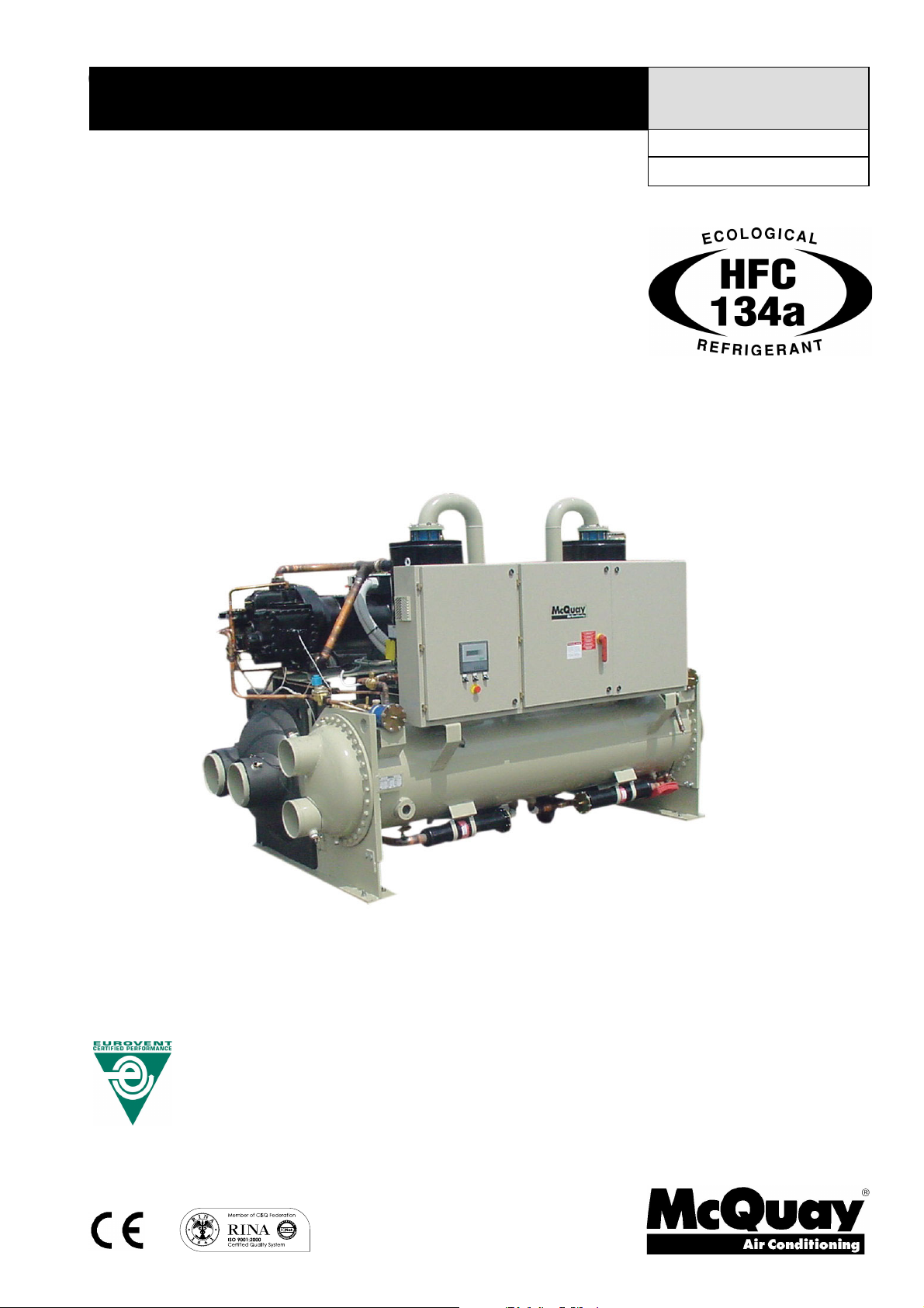
New water cooled screw chillers McQuay PFS “B”
McQuay International introduces their newest water cooled screw chillers equipped with new single screw
compressors.
McQuay water cooled PFS chillers equipped with 1 or 2 McQuay screw co mpressors are a new range of the unit
using the StarGate
the consultants and the end user. McQuay PFS units are designed to minimise energy cos ts while maximising the
refrigeration capacities. Once again McQuay has developed a line of chillers unsurpassed in performance and
quality that will meet the most stringent requirements of comfort cooling, ice storage and process applications.
McQuay’s chiller design experience, combined with outstanding features makes the PFS c hiller unmatched in the
industry.
TM
single screw compressors. They are manufactured by McQuay to satisfy the requirements of
Customer benefits
Design for every kind of requirement
Compared with competitors, PFS water cooled chiller offers surprising performance. PFS dual compressor unit
(with a single refrigerant circuit) takes full advantage of the total heat transfer surface over the use of two separate
refrigerant circuits when only one compressor is required to satisfy the thermal load.
McQuay has answered the challenge to create a reliable, energy efficient, environmentally safe with the
introduction of the new PFS screw compressor water-cooled chiller.
Lower noise – higher flexibility
The McQuay original compressor design with a single screw and twin rotors allows a constant gas flow. This
compression process completely eliminates gas pulsations. The oil injection also results in significant mechanical
noise reduction.
The twin gas compressor discharge chambers are designed to act as attenuators, based on the harmonic wave
principle with destructive interference, thus always resulting equal to zero. The extremely low noise compressor
performance affords the use of PFS chiller for all applications.
The reduced number of vibrations produced from the PFS chillers offers a surprisingly quiet operation eliminating
the noise transmission through the structure and the chilled water piping system.
Infinitely variable capacity control
Cooling capacity c ontrol is infinitely variable by means of a capacity slide controlled by microprocessor system.
Each unit has infinitely variable capacity control down to 12.5% (two compressors units), to 25% (one compressor
units). This modulation allows the compressor capacity to exactly match the building cooling load. The result is a
decrease in chiller energy costs, particularly at the part-load c onditions at which the chiller operates most of the
time. In order to optimize control sequence, each compressor load (and unload) from 95 to 100 % of its capacity
by one step.
Unmatched serviceability
Field serviceability has not been sacrificed. Inspection covers allows visual inspection of the main screw and
gaterotors. Suction valves allow easy isolation and field servicing of this unit.
Outstanding reliability features
Full factory testing of all the units ensures a trouble free start-up. Extensive test makes certain that each safety
and operating control is properly adjusted, and operates correctly.
803 B – 04/11 D – pag. 2/24
803 B – 04/07 D – pag. 2/24
Page 3
General characteristics
Ecological HCF 134a refrigerant
McQuay has designed and optimized StargateTMcompressors to operate with HFC 134a, ecological refrigerant
with zero ODP (Ozone Depletion Potential) and very low GWP (Global Warming Potential) that means low value of
the “direct effect” in the formula of TEWI (Total Equivalent
Warming Impact).
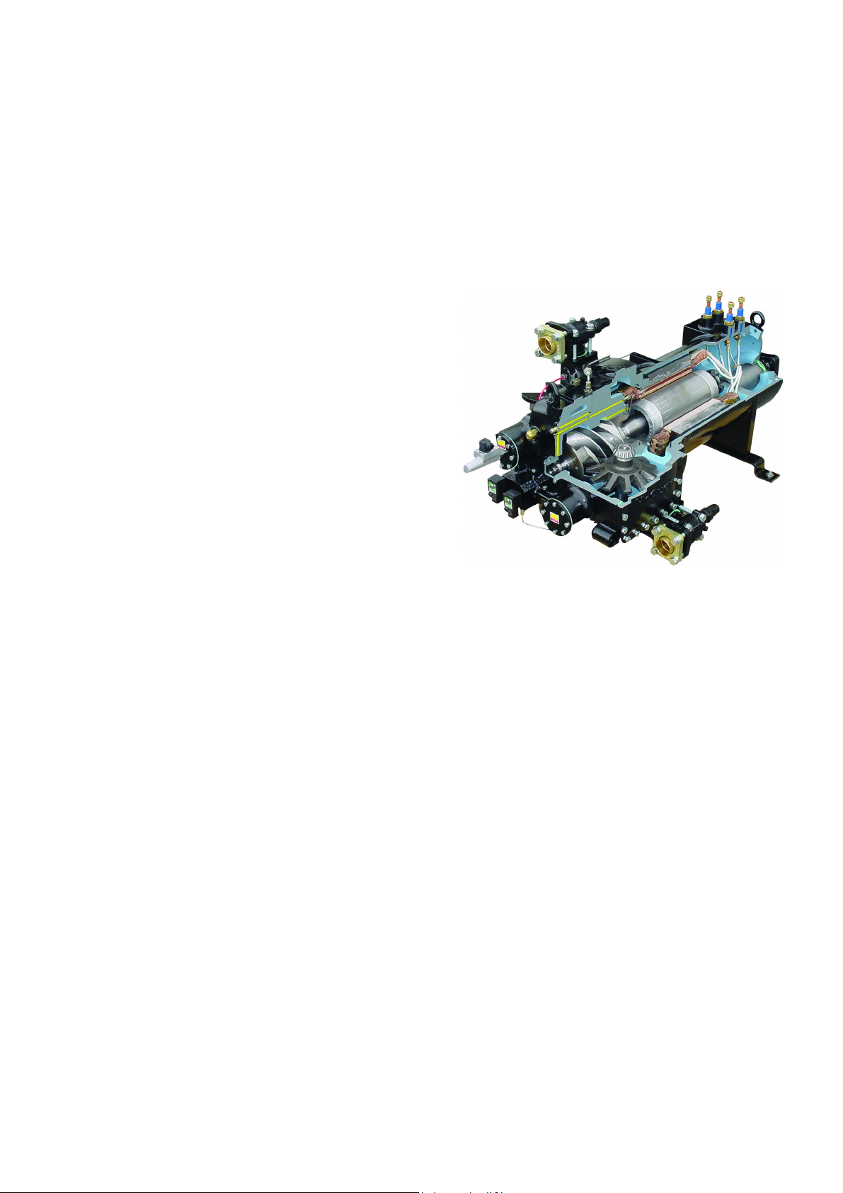
Screw compressors
The newes t StargateTMsingle-screw compressor has a well
balanced compression mechanism which cancels the screw
rotor load in both the radial and axial directions. Inherent to
the basic single-screw compressor design is the virtually
load-free operation, that gives main bearing des ign life of 3-4
times greater than twin-screws, and eliminates expensive
and complicated thrust balancing schemes. The two exactly
opposed gaterotors create two exactly opposed compression
cycles. Compression is made at the lower and upper parts of
the screw rotor at the same time, thus cancelling the radial
loads. Also, both ends of the screw rotor are subjected to
suction pres sure only, which cancels the axial loads and
eliminates the huge thrust loads inherent in twin-screw
compressors.
Oil injection is used for these compressors in order to get
high COP at high condensing pressure. PFS units are
provided with an high efficiency oil separator to maximise oil
extraction.
Compressors have a infinitely va riable capacity control down
to 25% of its total capacity. This control is made by means of
capacity slides controlled by microprocessors.
Standard start is star-delta type; Soft start type is available
(as option) in order to have lower inrush current.
Evaporator
Flooded shell-and-tube evaporator operating with refrigerant in shell and water in tubes. Replaceable water tubes
are fabricated from integral finned copper and mechanically bonded to steel tube sheets. The evaporator is PED
designed, constructed, inspected and stamped. Water side working pressure is designed for 10,5 bar. Vessels
include 1” FPT spring loaded pressure relief valves. Shell and non-connection water heads are insulated with 3/4”
thick closed cell insulation. Standard configuration on water connections side is 2 passes.
Condenser
Shell-and-tube type operating with refrigerant in shell and water in tubes. Replaceable water tubes are fabricated
from integral finned copper and mechanically bonded to steel tube sheets. Condenser is designed to conform
PED. Water side working pressure is designed for 10.5 bar. Standard configuration on water connections side is 2
passes.
Operative efficiency
The majority of comfort cooling systems operate at 60% or less of building design kW for most of the year. A great
number of those operating hours occur between 50% and 60% des ign cooling capacity. For that reason, PFS
chiller was designed to obtain excellent part load performance. This is achieved by a combination of individual
component features that include compressor design, operating control, double heat transfer surface with only one
compressor running (dual compressors unit), refrigerant flow control.
803 B – 04/11 D – pag. 3/24
Page 4

Servo Controlled modulating liquid level regulators
PFS are equipped with a modulating servo-controlled main expansion valve type controlled by a pilot float valve
type to perfectly modulate refrigerant flow to the evaporator, proportionally to the required capacity. This ensures a
stable regulation and economic operation, because pressure and temperature variations are strongly reduced.
Electrical panel
Power and control are located into two sections of the main panel that is manufactured to insure protection for all
weather conditions.
The power panel is fitted with a interlocked door main isolator to prevent access while power supply is on.
Electrical panel is IP43.
Power section includes - The power section includes contactors, all compressors fuses, and control circuit
transformer. Additional space is provided for an easy installation of the various optional accessories provided to
enhance the PFS units capabilities.
Certifications
All the PFS units are CE marked (89/392). McQuay Italia obtained ISO 9001:2000.
Water content in cooling circuits
The cooled water distribution circuits should have a minimum water content to avoid excessive compressors start
and stop.
In fact, each time the compressor starts up, an excessive quantity of oil goes from the compressor sump and
simultaneously there is a rise in the temperature of the compressor motor’s stator due to the inrush current during
the start-up. To prevent damage to the compressors, McQuay has envisaged the application of a device to limit
frequent stops and restarts.
During the span of one hour there will be no more than 6 starts of the compressor. The plant side should therefore
ensure that the overall water content allows a more constant functioning of the unit and consequently greater
environmental comfort. The minimum installation water content envisaged should be calculated with a certain
approximation using this simplified formula:
(1) Q = 35,83 X
(kW)P
°∆
where:
Q = Minimum content of the plant expressed in litres
P = Cooling capacity of the plant expressed i n kW
∆T = Entering/leaving water temperature difference of the evaporator expressed in °C
N = Number of compressors.
For a more accurate determination of the quantity of water, it is advisable to contact the designer of the plant.
1
X
)C(T
N
803 B – 04/11 D – pag. 4/24
Page 5

Microtech II Plu s controller
Microtech II Plus device is installed as standard on all the units; it can be used to alter unit set points and control
commands. A display illustrates the machine's operating status and programable parameters (setpoints) e.g.
temperatures and pressures of fluids (water, refrigerant). Device controls maximise the McQuay chillers energy
efficiency and reliability characteristics. It uses sophisticated software with predictive logic to select the most
energy ef ficient combination of compressor. The compressors are automatically rotated to ensure equal operating
hours. Microprocesso r device protects critical components in response to e xternal signals from its system sensors
measuring: motor temperatur es, refrigerant gas and oil pressures, electrical supply and evaporator.
Control section - main features:
• Management of the compressor capacity slide according to the distributed multiprocessor logic system
• Chillers enabled to work in partial failure condition thanks to the distributed multiprocessor logic system
• Full routine operation at condition of:
High thermal load
High evaporator entering water temperature (start-up)
• Display of evaporator entering/leaving water temperature
• Display of condensing-evaporating temperature and pressure, superheat temperature for each circuit
• Leaving water cooled temperature regulation (also available entering water regulation). Temperature
tolerance=0,2°C
• Compressors and evaporator/condenser pumps hours counter
• Display of Status Safety Devices
• Start up numbers and compressors working hours equalization
• Excellent management of compressors load
• Automatic re-start in case of power supply interruption
• External signal demand limit 0÷100%
• Soft load: starting load limitation (25÷100%) time based
• External air reset
• Current limitor
• High evaporator temperature start
Safety for each refrigerant circuit
High pressure (pressure switch)
Low pressure (pressure switch)
Compressor thermal
High Discharge Temperature on the compressor
Phase Monitor
Star / Delta Transition Failed
Low Delta Pressure between Suction and Discharge
System security
A serious alarm input (stops the unit)
A flow controller input (stops the unit)
A pump thermal input (stops the unit)
Remote on/off i nput without alarm signaling
Regulation type
Stabilized PID Proportional - Integral – Derivative regulation on the evaporator input probe for a perfect water
regulation (max ∆T=±0,2°C)
803 B – 04/11 D – pag. 5/24
Page 6
Microtech II Plus terminal
The Microtech II Plus terminal has following features:
• 4-lines by 20-character liquid crystal display
• Removable and remote key-pad
• Key-pad consisting of 15 keys “ clear language display ”
• Memory to protect the data
• General faults alarm led
• 4-level password acc ess to modify the setting
• Service report dislaying all working hours and general conditions
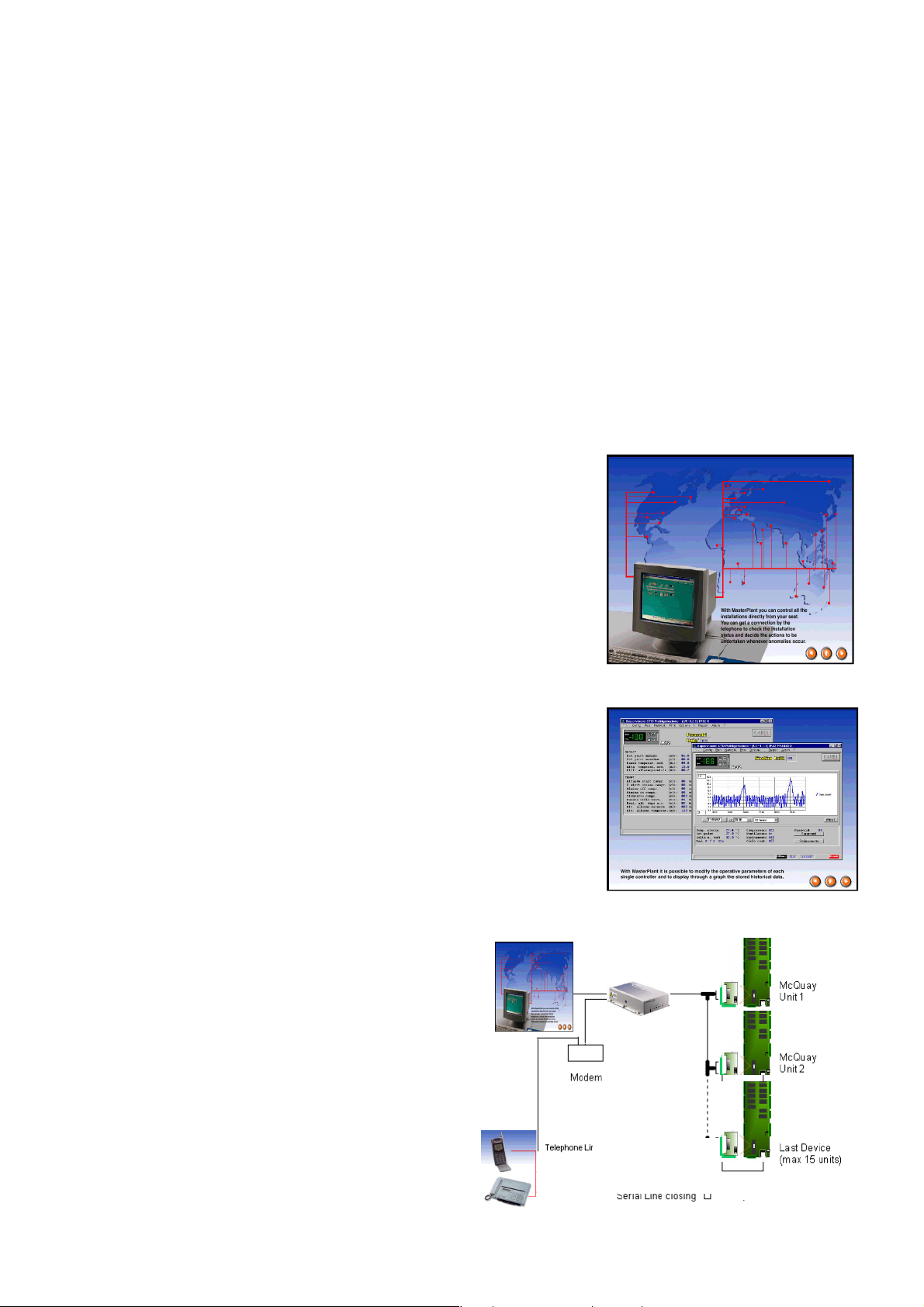
MicroPlantTM:
Solution for: tele-maintenance and supervisory systems
Microtech II Plus can be monitored locally or via modem by MicroPlant supervision program, that runs on PC
systems under Windows ’95 – ’98.
MicroPlant is the best solution:
• To centralise all the information in just one local and/or remote PC
• To check all the parameters for each unit connected
• To be informed immediately and automatically of any alarm situation via
modem - printouts
• Automatic printouts of alarms, parameters and graphs
• To control s everal plants located in different geographical areas from a
central station
• To manage the Service centers
MicroPlant allows:
• Visualization and modification of all the parameters for each controller
• Protection of the main parameters against incidental modifications
(different levels of passwords)
• Memorization of the detected values and visualization of their graphics
• Display, print-out and chronological memorization of the detected alarms
• Connection between local and remote computer via telephone line
(Modem)
Microtech II Plus remote control
Compatibility with supervisory systems is becoming
increasingly important in HVAC. Microtech II Plus allows
easy interfacing with BMS (Building Management Systems),
the external world that can be:
Landis & Staefa, Siemens, Johnson, Honeywell, Satc hwell,
Trend.
McQuay Chiller System Controller (CSC) is available as
option.
803 B – 04/11 D – pag. 6/24
Page 7

Standard Accessories (furnished on basic unit)
Modulating condenser water flow valve – Factory mounted on condenser outlet water connection, in order to
allow fast and safe unit starting. It is not supplied for condensers with water side pressures higher than 10 bar.
Discharge line check valve – Ensures compressors maintainence operations without any refrigerant loss.
Star Delta Compressors starter – For low inrush current and reduced starting torque.
Phase monitor – The phase monitor controls the voltage values on the supply line s topping the unit when the
calibration threshold is reached (± 10%). This safety device is automatically reset.
Evaporator connection w ater side Victaulic – Hydraulic joint with gasket for an easy and quick water
connection.
Insulation around the evaporator – Ins ulation 20 mm thickness to protect the evaporator against freezing.
Hour run meter – Digital compressors hour run meter.
General fault contactor – Contactor for the alarm warning.
Options (on request)
Brine double set point version (CB) - Dual leaving glycol mixture temperature setpoints. The lower setpoint can
go down to -8°C.
Compressor thermal overload relays - Safety devices against compressor motor overloading in addition to the
normal protection envisaged by the electrical windings.
Ammeter and voltmeter - Digital meters of unit drawn amperes and voltage values, installed on the electrical
control panel.
Condenser power factor correction - Installed on the electrical control panel to ensure it conforms to the plant
rules. (McQuay advices maximum 0,9).
Suction line shut off valve – Suction shut-off valve installed on the suction port of the compressor to facilitate
maintenance operation.
Flanged connections – Evaporator and condenser flanged connections (150 psig) are available instead of the
standard victaulic connections.
Marine water boxes – Evaporator and condenser can be furnished with marine water boxes with victaulic or
flanged connections (on request). To save time and work marine water boxes cover can be easily removed to
clean internal tubes without the disconnec tion of water pipes.
Double water pressure differential switch – Factory mounted differential switch is available as option to detect
evaporator and condenser loss of flow .
Flow switch - Supplied separately to be wired and installed on the evaporator water piping (by the customer).
Cu-Ni 90-10 condenser – To work with sea water the heat exchangers are fitted with Cu-Ni tubes and special
protection inside the end covers.
Rubber type antivibration mounts ( Pads ) - Supplied separately, must be positioned under the base of the unit.
Sound proof cabinet - Made of sheet metal and internally insulated, the cabinet is "integral kind" ( around the
whole chiller, not only around the compressors ) to reach the best performance in noise reduction.
Note: to realize the baseframe consider that the dimensions of the sound proof cabinet are 300 mm longer, 300 mm wider and
200 mm higher than the standard unit. The cabinet is supplied in a separated non assembled kit.
Witness tests - The units are normally tested at the test bench prior to the shipment. On request, a second test
can be carried out, at customer’s presence, in accordance with the procedures indicated on the test form. (Not
available for units with Glycol mixtures).
Soft start – Electronic starting device to reduce inrush current.
803 B – 04/11 D – pag. 7/24
Page 8
Installation notes
Warning
Installation and maintenance are to be performed only by qualified personnel who are familiar with local codes and
regulations, and who are experienced with this type of equipment. Must be avoided the unit installation in places
that could be considered dangerous for all the maintenance operations.
Handling
The chiller is mounted on heavy wooden skids to protect the unit from accidental damage and to permit easy
handling and moving. It is recommended that all moving and handling be performed with the skids under the unit
when possible and that the skids not be removed until the unit is in the final location.
If the unit must be hoisted, it is nec essary to lift the unit by attaching cables or chains at the lifting holes in the
evaporator tube sheets. Spreader bars must be used to protect the control cabinet and the other areas of the
chiller.
Location
A levelled and sufficiently strong floor is required.
Rubber-in-shear isolators can be furnished and field placed under each corner of the package. A rubber anti–skid
pad should be used under isolators if hold-down bolts are not used.
Vibration isolator in all water piping connected to the chiller are recommended to avoid straining the piping and
transmitting vibration and noise.
Evaporator and Condenser water flow and Delta T
Standard configuration on water side connections is 2 passes for both evaporator and condenser. Use pressure
drop curves to check if it’s the best solution.
In order to optimize performances with higher delta T ( lower water flow ), 3 passes evaporator and 3 or 4 passes
condenser configurations are available on request.
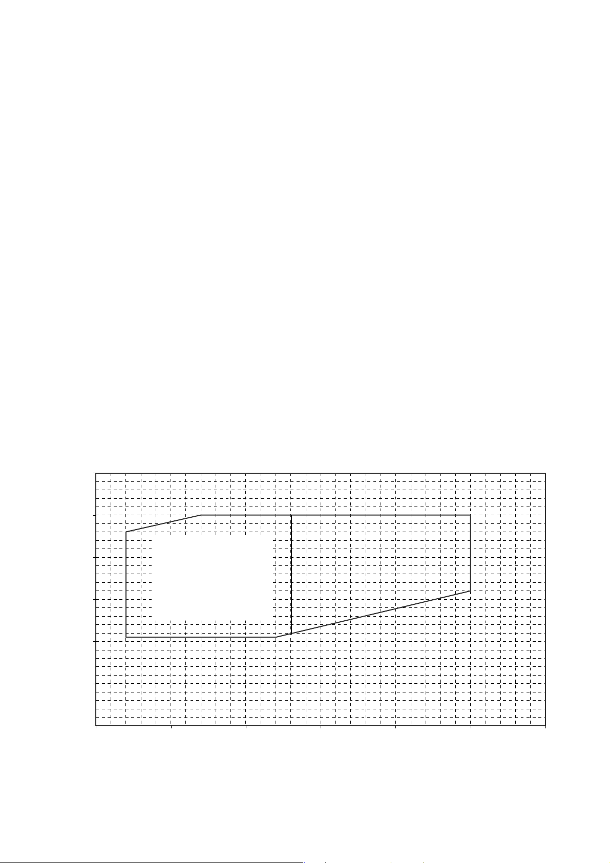
Operating Range
60
50
40
30
20
Condenser leaving temperature - °C
10
0
-10 -5 0 5 10 15 20
6HHWKHQRWH
Evaporator leaving temperature - °C
Note:
the use of glycol is necessary
803 B – 04/11 D – pag. 8/24
for
evaporator leaving water temperature below +3°C.
Page 9

Table 1 – Operating limits
PFS 103.1÷296.2 HFC 134a
Max evaporator leaving water temperature °C
Min evaporator leaving water temperature (without glycol) °C
Min evaporator leaving water temperature (with glycol) °C
Max condenser leaving water temperature °C
15
3
-8
50
Table 2 – Evaporator fouling factors
Fouling factors
m2°C / k W
0,0176 1,000 1,000 1,000
0,0440 0,978 0,986 0,992
0,0880 0,957 0,974 0,983
0,1320 0,938 0,962 0,975
Cooling capacity
correction factor
Power input
corretion factor
COP
correction factor
Table 3 – Condenser fouling factors
Fouling factors
m2°C / k W
0,044 1,000 1,000 1,000
0,088 0,990 1,018 0,973
0,132 0,981 1,036 0,945
Cooling capacity
correction factor
Power input
corretion factor
COP
correction factor
Table 4 – Ethylene glycol and low ambient temperature correction factors
Air ambient temperature °C
% of ethylene glycol by weight
Cooling capacity correction factor
Power input correction factor
COP correction factor
Flow rate correction factor
Water pressure drops correction factor
-3 -8 -15 -23 -35
10 20 30 40 50
0,991 0,982 0,972 0,961 0,946
0,996 0,992 0,986 0,976 0,966
0,995 0,990 0,986 0,985 0,979
1,013 1,040 1,074 1,121 1,178
1,070 1,129 1,181 1,263 1,308
Table 5 – Low temperature operation performance factors
Ethylene glycol/water leaving temperature °C
Min. % of ethylene glycol
Cooling capacity correction factor
Power input compressors correction factor
2 0 -2 -4 -6 -8
10 20 20 30 30 30
0,842 0,785 0,725 0,670 0,613 0,562
0,95 0,94 0,92 0,89 0,87 0,84
803 B – 04/11 D – pag. 9/24
Page 10

Nomenclature
P F S “B” 249 . 2 134
P
F
S
“B”
103÷296
1
2
134
Water cooled
Flooded
Screw compressor
Release
Unit size
N°of compressors
Refrigerant HFC 134a
803 B – 04/11 D – pag. 10/24
Page 11

Physical data PFS “B”
PFS Unit size 103.1 124.1 147.1 208.2 229.2 249.2
Cooling capacity (1) kW
Power input (1) kW
COP (1)
McQuay Screw compressors No.
Refrigerant circuits No.
Min % of capacity reduction %
Refrigerant charge HFC 134a kg
Oil charge l
369 445 521 734 816 895 976 1050
65 78 90 130 143 155 168 180
5.7 5.7 5.8 5.7 5.7 5.8 5.8 5.8
11122222
11111111
25,0 25,0 25,0 12,5 12,512,5 12,512,5
130 165 180 200 215 230 274 290
30 30 30 60 60 60 60 60
272.2
296.2
Evaporator
Evaporators / water volume No./l
Max water operating pressure bar
1/78 1/107 1/134 1/184 1/210 1/210 1/281 1/302
10,5 10,5 10,5 10,5 10,5 10,5 10,5 10,5
Condenser
Condensers / water volume No./l
Max water operating pressure bar
1/83 1/111 1/133 1/181 1/199 1/243 1/243 1/263
10,5 10,5 10,5 10,5 10,5 10,5 10,5 10,5
Weight and dimensions
Shipping weight kg
Operating weight kg
Unit length (2) mm
Unit width mm
Unit height mm
Note: (1) Nominal cooling capacity and power input are based on: 12/7 °C entering/leaving evaporator water temperature;
30/35 °C entering/leaving condenser water temperature.
(2) Length includes modulating condenser water flow valve.
3089 3370 3603 5546 5636 6007 6448 6598
3250 3588 3870 5911 6045 6460 6972 7163
3625 3860 3860 4145 4145 4145 4145 4145
1551 1551 1551 1743 1743 1808 1910 1910
2250 2250 2250 2300 2300 2300 2300 2300
Electrical data PFS “B”
PFS unit size 103.1 124.1 147.1 208.2 229.2 249.2 272.2 296.2
Standard voltage (1)
Nominal unit current (2) A
Max unit current (3) A
Max unit inrush current (4) A
Max unit current for wires sizing (5) A
Max short circuit holding current kA
Notes: (1) Allowed voltage tolerance ± 10%. Voltage unbalance between phases must be within ± 3%.
(2) Absorbed current referred to nominal condition: 12/7 °C entering/leaving evaporator water temperature; 30/35 °C
entering/leaving condenser water temperature.
(3) Absorbed current referred to the following conditions: 15/10 °C entering/leaving evaporator water temperature;
45/50°C entering/leaving condenser water temperature.
(4) Absorbed current of compressor n°1 at 75% + inrush current of the other compressor.
(5)
Compressors FLA (Full Load Ampere).
112 129 148 224 244 258 277 295
137 178 205 302 331 357 385 410
367 367 367 535 550 561 575 588
142 183 210 307 336 362 390 415
25 25 25 25 25 25 25 25
400 V – 3Ph – 50 Hz
803 B – 04/11 D – pag. 11/24
Page 12

Sound pressure level PFS “B”
Sound pressure level at 1 m from the unit in free field ( rif. 2 x 10⁻⁵)PFS
Unit size
103.1
124.1
147.1
208.2
229.2
249.2
272.2
296.2
Note: Average sound pressure level rated in accordance to ISO 3744, free field semispheric conditions.
63 Hz 125 Hz 250 Hz 500 Hz 1000 Hz 2000 Hz 4000 Hz 8000 Hz dBA
63,5 70,5 80,0 74,5 74,0 68,5 60,5 50,5
64,5 71,5 81,0 75,5 75,0 69,5 61,5 51,5
65,5 72,5 82,0 76,5 76,0 70,5 62,5 52,5
66,5 73,5 83,0 77,5 77,0 71,5 63,5 53,5
67,0 74,0 83,5 78,0 77,5 72,0 64,0 54,0
67,5 74,5 84,0 78,5 78,0 72,5 64,5 54,5
68,0 75,0 84,5 79,0 78,5 73,0 65,0 55,0
68,5 75,5 85,0 79,5 79,0 73,5 65,5 55,5
Sound pressure level PFS “B” with sound proof cabinet
Sound pressure level at 1 m from the unit in free field ( rif. 2 x 10⁻⁵)PFS
Unit size
103.1
124.1
147.1
208.2
229.2
249.2
272.2
296.2
63 Hz 125 Hz 250 Hz 500 Hz 1000 Hz 2000 Hz 4000 Hz 8000 Hz dBA
58,3 63,5 70,1 62,8 60,6 54,5 47,1 37,1
59,3 64,5 71,1 63,8 61,6 55,5 48,1 38,1
60,3 65,5 72,1 64,8 62,6 56,5 49,1 39,1
61,3 66,5 73,1 65,8 63,6 57,5 50,1 40,1
61,8 67,0 73,6 66,3 64,1 58,0 50,6 40,6
62,3 67,5 74,1 66,8 64,6 58,5 51,1 41,1
62,8 68,0 74,6 67,3 65,1 59,0 51,6 41,6
63,3 68,5 75,1 67,8 65,6 59,5 52,1 42,1
78,0
79,0
80,0
81,0
81,5
82,0
82,5
83,0
66,0
67,0
68,0
69,0
69,5
70,0
70,5
71,0
Note: Average sound pressure level rated in accordance to ISO 3744, free field semispheric conditions.
Sound pressure level correction factor for different distances
PFS
Unit size
103.1
124.1
147.1
208.2
229.2
249.2
272.2
296.2
1 5 10 15 20 25
0 -8,3 -13,2 -16,3 -18,6 -20,4
0 -8,3 -13,2 -16,3 -18,6 -20,4
0 -8,3 -13,2 -16,3 -18,6 -20,4
0 -8,1 -13,0 -16,1 -18,4 -20,2
0 -8,1 -13,0 -16,1 -18,4 -20,2
0 -8,1 -13,0 -16,1 -18,4 -20,2
0 -8,0 -12,9 -16,0 -18,3 -20,1
0 -8,0 -12,9 -16,0 -18,3 -20,1
Distance (m)
803 B – 04/11 D – pag. 12/24
Page 13

Standard ratings PFS “B” 103.1 ÷ 296.2
ENTERING CONDENSER WATER TEMPERATURE - °C
PFS
Unit
size
103.1
124.1
147.1
208.2
229.2
249.2
272.2
296.2
water
Cool.
temperature °C
Leaving chilled
4 347 56 6,2 332 64 5,2 317 72 4,4 301 81 3,7 284 91 3,1
5 359 57 6,3 344 64 5,4 329 72 4,5 312 81 3,8 295 91 3,2
6 372 57 6,5 357 65 5,5 340 73 4,7 324 82 4,0 306 92 3,3
7 385 57 6,7 369 65 5,7 353 73 4,8 335 82 4,1 318 92 3,5
8 398 58 6,9 382 65 5,9 365 73 5,0 347 82 4,2 329 92 3,6
9 411 58 7,1 395 65 6,0 377 74 5,1 359 83 4,4 341 92 3,7
10 425 58 7,3 408 66 6,2 390 74 5,3 372 83 4,5 353 93 3,8
4 418 67 6,3 400 76 5,2 381 86 4,4 362 97 3,7 341 109 3,1
5 433 67 6,4 415 77 5,4 395 87 4,6 375 98 3,8 354 110 3,2
6 449 68 6,6 429 77 5,6 410 87 4,7 389 98 4,0 368 110 3,4
7 464 68 6,8 445 78 5,7 424 88 4,8 403 98 4,1 381 110 3,5
8 480 68 7,0 460 78 5,9 439 88 5,0 418 99 4,2 396 110 3,6
9 497 69 7,2 476 78 6,1 455 88 5,2 433 99 4,4 410 111 3,7
10 513 69 7,5 492 79 6,3 470 89 5,3 448 99 4,5 425 111 3,8
4 491 78 6,3 469 89 5,3 447 100 4,5 424 112 3,8 400 126 3,2
5 508 79 6,5 486 89 5,4 463 100 4,6 440 113 3,9 416 126 3,3
6 526 79 6,7 503 90 5,6 480 101 4,8 456 113 4,0 431 126 3,4
7 544 79 6,9 521 90 5,8 497 101 4,9 473 113 4,2 447 127 3,5
8 563 79 7,1 539 90 6,0 515 102 5,1 490 114 4,3 464 127 3,6
9 582 80 7,3 558 91 6,2 533 102 5,2 507 114 4,4 481 128 3,8
10 602 80 7,6 577 91 6,3 551 103 5,4 525 115 4,6 498 128 3,9
4 690 113 6,1 661 128 5,2 630 144 4,4 598 162 3,7 565 182 3,1
5 715 114 6,3 685 129 5,3 653 145 4,5 621 163 3,8 587 183 3,2
6 740 114 6,5 709 129 5,5 677 146 4,7 644 163 3,9 609 183 3,3
7 766 115 6,7 734 130 5,7 701 146 4,8 667 164 4,1 631 184 3,4
8 792 116 6,8 760 130 5,8 726 147 4,9 691 165 4,2 654 184 3,6
9 818 116 7,0 785 131 6,0 751 147 5,1 715 165 4,3 678 185 3,7
10 845 117 7,3 812 131 6,2 777 148 5,3 740 166 4,5 702 185 3,8
4 767 124 6,2 733 141 5,2 699 159 4,4 662 179 3,7 625 201 3,1
5 795 125 6,4 760 142 5,4 724 160 4,5 688 180 3,8 649 202 3,2
6 823 125 6,6 788 142 5,5 751 160 4,7 713 180 4,0 674 202 3,3
7 852 126 6,8 816 143 5,7 778 161 4,8 739 181 4,1 699 203 3,5
8 881 127 7,0 844 144 5,9 806 162 5,0 766 182 4,2 725 203 3,6
9 911 127 7,2 874 144 6,1 834 162 5,1 794 182 4,4 752 204 3,7
10 942 128 7,4 903 145 6,2 863 163 5,3 822 183 4,5 779 204 3,8
4 843 134 6,3 806 153 5,3 768 173 4,4 728 195 3,7 688 219 3,1
5 873 135 6,5 835 154 5,4 796 174 4,6 756 195 3,9 714 219 3,3
6 903 135 6,7 865 154 5,6 825 174 4,7 784 196 4,0 741 220 3,4
7 935 136 6,9 895 155 5,8 854 175 4,9 812 197 4,1 768 220 3,5
8 967 137 7,1 926 156 5,9 885 176 5,0 841 197 4,3 797 221 3,6
9 1000 137 7,3 958 157 6,1 915 177 5,2 871 198 4,4 825 221 3,7
10 1033 138 7,5 991 157 6,3 947 177 5,3 902 199 4,5 855 222 3,9
4 918 146 6,3 878 166 5,3 836 187 4,5 793 210 3,8 749 236 3,2
5 951 147 6,5 910 167 5,5 867 188 4,6 823 211 3,9 778 236 3,3
6 984 147 6,7 942 168 5,6 899 189 4,8 854 212 4,0 807 237 3,4
7 1019 148 6,9 976 168 5,8 931 190 4,9 885 213 4,2 837 238 3,5
8 1054 149 7,1 1010 169 6,0 964 191 5,1 917 213 4,3 868 238 3,6
9 1090 149 7,3 1045 170 6,2 998 191 5,2 950 214 4,4 900 239 3,8
10 1126 149 7,5 1080 170 6,3 1032 192 5,4 983 215 4,6 932 240 3,9
4 988 157 6,3 944 178 5,3 898 200 4,5 852 224 3,8 804 252 3,2
5 1024 158 6,5 978 179 5,5 932 201 4,6 884 225 3,9 835 253 3,3
6 1060 158 6,7 1014 180 5,6 966 202 4,8 917 226 4,1 867 253 3,4
7 1097 159 6,9 1050 180 5,8 1001 203 4,9 951 227 4,2 900 254 3,5
8 1135 159 7,1 1087 181 6,0 1037 204 5,1 986 228 4,3 934 255 3,7
9 1174 159 7,4 1124 182 6,2 1074 205 5,2 1022 229 4,5 968 256 3,8
10 1213 159 7,6 1163 182 6,4 1111 206 5,4 1058 230 4,6 1003 257 3,9
25 30 35 40 45
cap.
(kW)
Pow.
input
(kW)
COP
Cool.
cap.
(kW)
Pow.
input
(kW)
COP
Cool.
cap.
(kW)
Pow.
input
(kW)
COP
Cool.
cap.
(kW)
Pow.
input
(kW)
COP
Cool.
cap.
(kW)
Pow.
input
(kW)
COP
Note: (1) Nominal cooling capacity and power input are based on ∆T=5°C entering/leaving condenser water temperature;
evaporator fouling factor=0,0176 m
2
°C/kW; condenser fouling factor=0,0440 m2°C / k W .
803 B – 04/11 D – pag. 13/24
Page 14

PFS “B” - 2 passes evaporator water pressure drop
Pressure drop (kPa)
Water flow rate (l/s)
803 B – 04/11 D – pag. 14/24
Page 15

PFS “B” - 3 passes evaporator water pressure drop
Pressure drop (kPa)
Water flow rate (l/s)
803 B – 04/11 D – pag. 15/24
Page 16

PFS “B” - 2 passes condenser water pressure drop
Pressure drop (kPa)
Water flow rate (l/s)
803 B – 04/11 D – pag. 16/24
Page 17

PFS “B” - 3 passes condenser water pressure drop
Pressure drop (kPa)
Water flow rate (l/s)
803 B – 04/11 D – pag. 17/24
Page 18

PFS “B” - 4 passes condenser water pressure drop
p(
)
kPa
Pressure dro
Water flow rate (l/s)
803 B – 04/11 D – pag. 18/24
Page 19

Dimensions PFS “B” 103.1
Dimensions PFS “B” 124.1-147.1
803 B – 04/11 D – pag. 19/24
Page 20

Dimensions PFS “B” 208.2-229.2
Dimensions PFS “B” 249.2
803 B – 04/11 D – pag. 20/24
Page 21

Dimensions PFS “B” 272.2-296.2
803 B – 04/11 D – pag. 21/24
Page 22

PFS “B” Frame 4 - Technical specifications
To supply and install, where specified in the project n ..... unit(s) water cooled chiller with cooling capacity of .....
kW, to c ool ..... l/sec. of water from ..... °C to ....., condenser entering water temperature ….°C, condenser leaving
water temperature ….°C. The unit should work with electricity at ..... V, 3ph, 50Hz. The electrical power absorbed
should not exceed ..... kW. The units COP will be at least ..... at the working conditions of the project. Part load
COP will be at least ..... at the working conditions of the project. For the units with 1 or 2 compressors the chillers
will have only one refrigerant circ uit, and the electronic microprocessor will allow the starting of the c ompressors.
Each chiller will be factory assembled on a robust baseframe. The unit will be tested at full load in the factory at
the nominal working conditions and water temperatures . Before shipment a full test will be held to avoid any
losses, and the units will be filled with oil and refrigerant.
Refrigerant - only HFC 134a
Noise level and vibrations – Sound pressure level at 1 meter distance in free f ield shall not exceed ………dBA
Vibration level should not exceed 2 mm/s.
Units will have the following components:
Compressors - The compressor should be single screw type with one main screw rotor that meshes with two
diametrically opposed gaterotors. The two exactly opposed gaterotors create two exactly opposed compression
cycles which results in balanced forces acting on the compressor. The gaterotors should be constructed of a
carbon impregnated engineered composite material. The gaterotor supports will be constructed of cast iron. The
semi-hermetic compressor should be gas-cooled.
Oil injection shall be used for this compressor in order to get high COP at high condensing pressure. The unit
should be provided with an oil separator and it will be the high efficiency, augmented gas impingement type to
maximise oil extraction.
Evaporator - The units will be supplied with shell-and-tube flooded type evaporator (refrigerant flow in the shell
and water flow i n tubes). Replaceable tubes will be fabricated from integral finned copper and mechanically
bonded to steel tube sheet. Refrigerant side will be ISPESL designed, constructed, inspected and stamped. Water
side working pressure should be designed for 10,5 bar. Vessels will include spring loaded pres sure relief valves.
Shell and non-connection water heads will be insulated with 3/4 ” thick closed cell insulation.
Condenser – Condenser will be shell-and-tube type operating with refrigerant in shell and water in tubes.
Replaceable water tubes should be fabricated from integral finned copper and mechanically bonded to steel tube
sheets. Condenser will be designed to conform ISPESL. Water side working pressure should be designed for 10.5
bar.
Servo controlled modulating liquid level regulators - The refrigerant circuit will be equipped with a modulating
servo-controlled main ex pansion valve type controlled by a pilot float valve type to perfectly modulate refrigerant
flow to the evaporator, proportionally to the required capacity. This will ensure a stable regulation and economic
operation, because pressure and temperature variations will be strongly reduced.
Modulating condenser water flow valve – It is factory mounted on condenser outlet water connection, in order to
allow fast and safe unit starting. It is not supplied for condensers with water side pressures higher than 10 bar.
Control panel - Field power connection, control interlock terminals, and unit control system should be centrally
located in an electric panel (IP 43). Power and s tarting controls should be separate from safety and operating
controls in different compartments of the same panel. Starting will be star/delta type. Power and starting controls
should include fuses and c ontactors for each compressor winding. Operating and safety controls should include
energy saving control; emergency stop switch; overload protection for compressor motor; high and low pressure
cut-out switch; compressor lead-lag switch (on 2 compres sor units only); c ut-out switch for each compressor.
All of the information regarding the unit will be reported on a display and with the internal built-in calender and
clock that will switch the unit ON/OFF during day time all year long.
Regulation of cooling capacity - Each unit will have a microproces sor for the control and operation of the unit
that should have a infinitely variable capacity control down to 12,5% (two compressors) or to 25% (one
compressor) of the cooling capacity.
Refrigerant piping - Refrigerant circuit should include a factory insulated suction line, manual liquid line shut-off
valve with charging connection, refrigerant filter drier with replaceable core, sensor indicator, servo controlled
liquid regulator and relief valve.
will be accepted.
803 B – 04/11 D – pag. 22/24
Page 23

803 B – 04/11 D – pag. 23/24
Page 24

We reserve the right to make changes in design and construction at any time without notice, thus the cover picture is not binding.
McQuay partecipa al programma di
Certificazione Eurovent.
I prodotti interessati figurano nella Guida
Eurovent dei Prodotti Certificati.
McQuay Italia S.P.A.
S.S. Nettunense, km 12+300 – 00040 Cecchina (Roma) Italia – Tel. (06) 937311 – Fax (06) 9374014 – Email: info@mcquayeurope.com
www.mcquayeurope.com
McQuay is participating in the Eurovent
Certification Programme
Product are as listed in the Eurovent
Directory of Certified Products
 Loading...