

Page 1
Page 2
Page 3
Introduction
McQuay
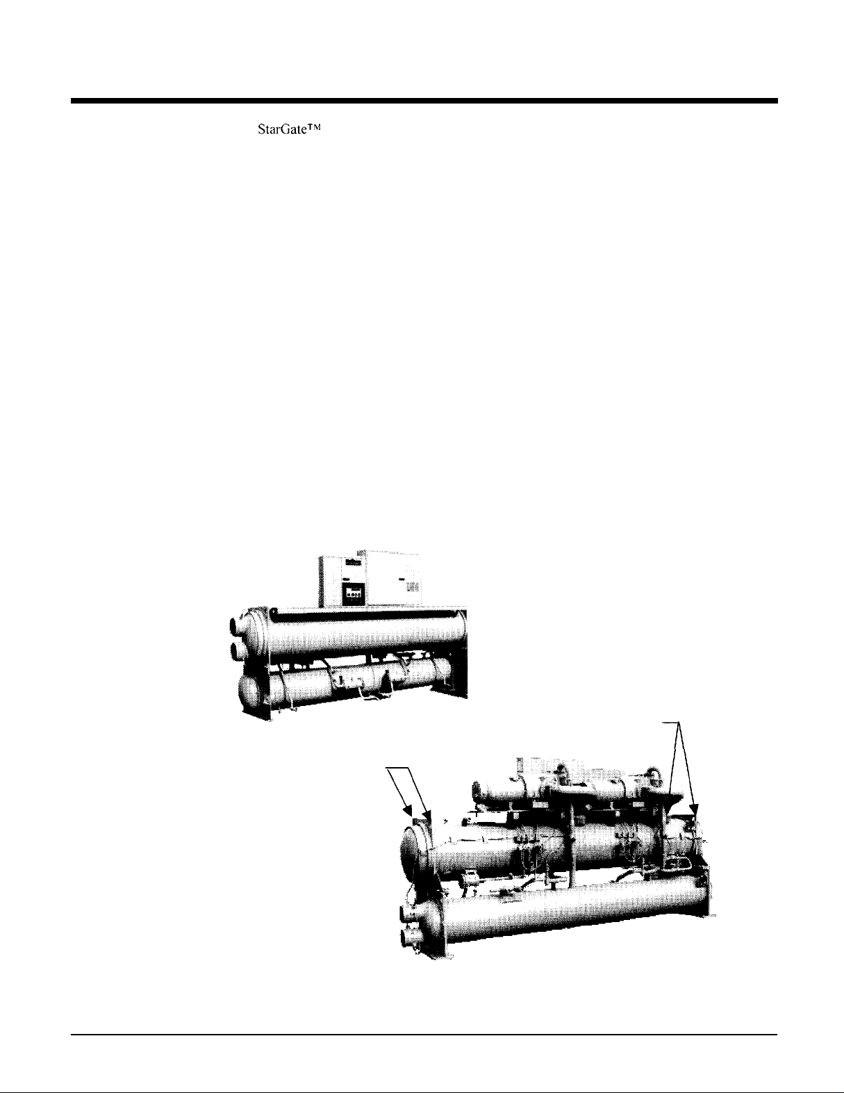
charged, tested and ready for installation. Each unit consists of a water-cooled condenser with
integral subcooler, multiple accessible semi-hermetic single screw compressors. replaceable tube
shell-and-tube evaporator. and complete refrigerant piping. Liquid line components included are
manual liquid line
sightglass/moisture
heaters, and an advanced fully integrated microprocessor control system.
automatic operation. (the high and low pressure controls are external from the electrical control
center). Compressors are protected by solid-state overload protection and over temperature
protection.
StarGateTM
The electrical control center includes all safety and operating controls necessary for dependable
Field
water-cooled chillers are completely assembled. factory wired. evacuated.
shutoff valves. charging valves. filter-dryers. liquid line solenoid valves,
indicators. and electronic expansion valves. Other features include compressor
installed fused
disconnect Sw itch (furnished by
others) offers additional protection.
Receiving and Handling
Inspect the unit immediately after receipt for
all claims for handling and shipping damage are
shipping
extreme care when rigging the equipment to prevent damage to the control center. or refrigerant
piping. See Dimensional Data for the center
eyes are located (see Figure I ). Use spreader bars between the ri
control center.
skid
in place until the unit is in final position. This will aid in handling the equipment. Use
Lift the unit
by
fastening the ri
gging
Figure I, Rigging Eyes
possible
of gravity of the
hooks to
damage.
the
responsibility
the
four corners of the evaporator where the rigging
The unit is shipped FOB factory and
of the
consignee. Leave the
unit.
gging lines to prevent damage to the
IM
663
Rigging eyes
Rigging eyes
3
Page 4
Installation
Installation must be performed by qualified personnel who are familiar with local codes
regulations, and experienced with this type of equipment
Start-up by
excluding Mexico. Two weeks prior notification of start-up is required. The contractor should obtain
a copy of the Start-up Scheduled Request Form from the sales representative or from the nearest
McQuayService office.
McQuayService
is included on all units sold for installation within North America
Location and Mounting
Mount the unit on a level concrete or steel base. Service clearance (at either end of the unit) is 14 feet
for units with
Evaporator and condenser tubes are rolled into the tube sheets to permit replacement. Clearance at all
other points, including the top, is 3 feet.
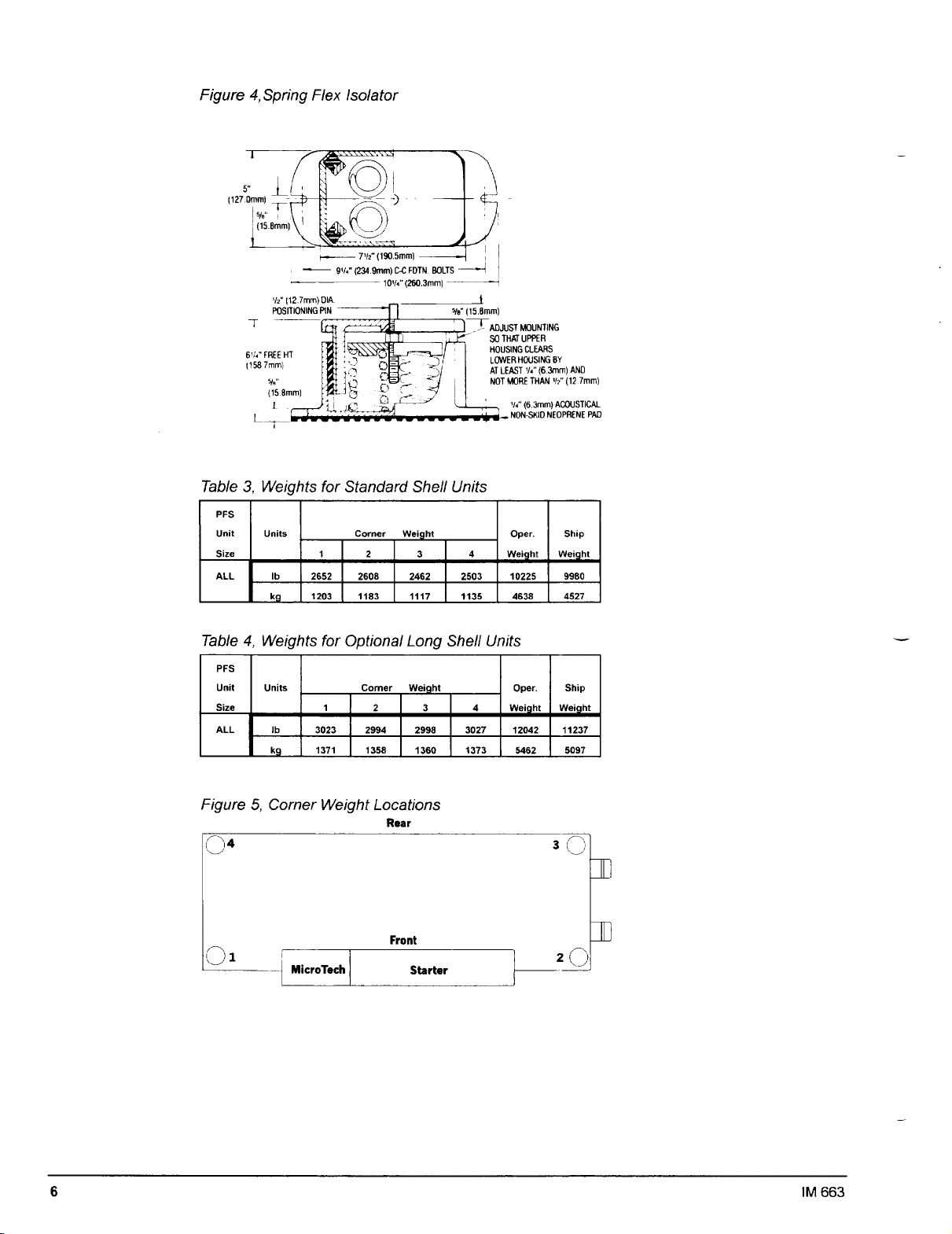
Make certain the floor or structural support is adequate to support the full operating weight of the
complete unit. Optional rubber-in-shear pads. or spring isolators can be ordered for use under each
corner of the base members.
although mounting holes are provided in the unit support at the four corners.
12-foot
long standard shells and 18 feet for units with
It is not necessary to bolt the unit to the mounting slab or frame work:
16-foot
long optional shells.
Compressor Condensation
Condensation occurs on the compressor surface when the temperature of the compressor surface is
lower than the ambient dew point temperature. Drain pans with drain connections are provided
underneath each compressor to collect the condensate. The compressor motor housing extends past
the drain pans. Install a floor drain close to the unit to collect condensate from motor housing and
condensate pans.
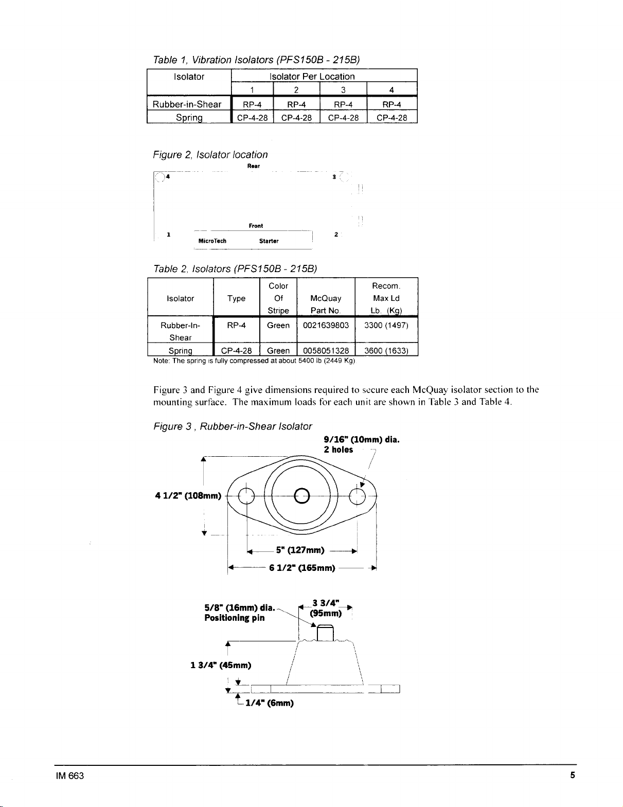
Vibration Isolators
Vibration isolator pads are shipped with the unit for field installation. These pads provide minimal
isolation. Vibration isolators are recommended on all upper level installations where vibration
transmission is a consideration. When vibration isolators are used. install springs under the main unit
supports. Adjust spring so the upper housing clears lower housing by at least
more than
Install vibration eliminators in water piping to reduce piping strain. vibration. and noise. Table
spring and rubber-in-shear isolators for all PFS unit sizes
4
1/2"
(1
3mm).
If hold-down bolts are not used. install a rubber anti-skid under isolators.
1/4"
(6mm) and not
l
lists
IM 663
Page 5
Page 6
Page 7
Evaporator and Condenser Water Piping
PFS evaporators and condensers are equipped with either victaulic or flange connections. The
installing contractor must provide matching connections.
Remove the solid-state temperature sensor and thermostat bulbs from the wells to prevent
damage to those components when welding on the victaulic or flange connections.
Connect the condenser with the inlet
condenser water will discharge from the top connection.
Support piping to reduce weight and strain on the fittings and connections. Be sure piping is
adequately insulated.Install a cleanable
piping. install enough
without draining the complete system.
shutoff
valves
water
entering at the bottom to maximize subcooling. The
20-mesh
to permit draining water from the evaporator or condenser
water strainer in evaporator and condenser water
CAUllUN
Freeze Notice: Neither the evaporator nor the condenser is self-draining. Both must be
blown out.
I
Include thermometers at the inlet and outlet connections and air vents at the high points of piping.
The water heads can be interchanged (end for end) allowing water connections to be made at either
end of the unit. Use new head gaskets when interchanging water heads. When water pump noise is
objectionable, use rubber isolation sections at both the inlet and outlet of the pump. Vibration
eliminator sections in the condenser inlet and outlet water lines are not normally required. Where
noise and vibration are critical, and unit is mounted on spring isolators, flexible piping connections
are necessary.
Water treatment
If unit is operating with a cooling tower, clean and flush cooling tower.
or bleedoff is operating. Atmospheric air contains many contaminants which increases the need for
water treatment. The use of untreated water may result in corrosion, erosion, sliming, scaling, or
algae formation. A water treatment service is recommended.
responsible for damage or faulty operation from untreated or improperly treated water.
McQuay
Make sure tower “blowdown”
International is not
Head pressure control, tower system
The minimum entering water temperature to the condenser must not be lower than 70°F (2
Use a three-way bypass valve around the tower to modulate the condenser water flow.Figure 6 shows
a three-way pressure actuator water regulating valve used for cooling applications. This regulating
valve will assure an adequate condensing pressure if the inlet condenser water temperature falls below
70°F). An optional
valve or a varible speed condenser pump.
IM
663
AOX-4
board located in the
MicroTech
panel will control a cooling tower bypass
I _
1°C).
7
Page 8
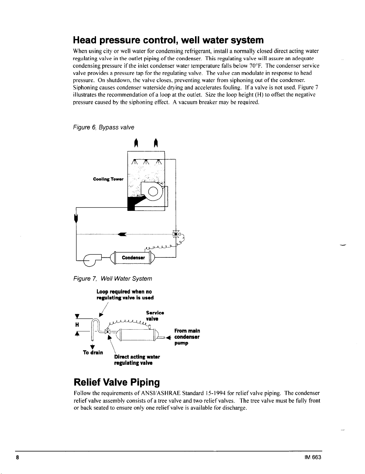
Head pressure control, well water system
When using city or well water for condensing refrigerant, install a normally closed direct acting water
regulating valve in the outlet piping of the condenser. This regulating valve will assure an adequate
condensing pressure if the inlet condenser water temperature falls below 70°F. The condenser service
valve provides a pressure tap for the regulating valve. The valve can modulate in response to head
pressure. On shutdown. the valve closes. preventing water from siphoning out of the condenser.
Siphoning causes condenser waterside drying and accelerates fouling. If a valve is not used, Figure 7
illustrates the recommendation of a loop at the outlet. Size the loop height (H) to offset the negative
pressure caused by the siphoning effect. A vacuum breaker may be required.
Figure 6, Bypass valve
Figure 7, Well Water System
Loop required when no
regulating valve is used
V-d
H
Kl-
r-
ld
f
To drain
/
T
Direct acting water
regulating valve
Service
valve
Y
From main
+ condenser
pump
Relief Valve Piping
Follow the requirements of ANSUASHRAE Standard 15- 1994 for relief valve piping. The condenser
relief valve assembly consists of a tree valve and two relief valves. The tree valve must be fully front
or back seated to ensure only one relief valve is available for discharge.
8
IM 663
Page 9
Temperature and Water Flow Limitations
“F
(-8.9”C)
PFS units are designed to operate in conditions from
temperature on the evaporator side and 70°F (2 I. 1 “C) to 95°F (35°C) entering water temperature on
the condenser side.
Glycol in the evaporator is required on all applications below 40°F (4.4”C) leaving evaporator
fluid temperature. The maximum allowable water temperature to the cooler in a non-operating cycle
is
10j°F (40.6”(Z).
(46.1 “C).
control. Flow rates above the maximum values will result in unacceptable pressure drops. excessive
nozzle and tube erosion and possibly cause tube failure.
The non-operating leaving condenser water temperature maximum is 115°F
Flow rates below the minimum values may cause freeze-up problems, scaling and poor
2 1
to 55°F (1O’C) leaving water
Evaporator Freeze Protection
When freeze protection is a concern, do the following:
1. If the unit will not be operated during the winter. drain and flush the evaporator and chilled water
piping with glycol Drain and vent connections are provided on the evaporator.
2.
When using a cooling tower, add glycol solution to the chilled water system. Freeze point should
be approximately 10°F
Note: Freeze damage is not considered a warranty failure and is not the responsibility of
McQuay
3.
International.
Insulate field water piping. especially on the chilled water side.
(5.6”C) below minimum design ambient temperature.
Condenser Protection and Design Considerations
If pond or river water is used as a condensing medium and the water valves leak, the condenser and
liquid line refrigerant temperature could drop below the equipment room temperature on the
cycle. This problem occurs when cold water continues to circulate through the condenser and the unit
remains off due to satisfied cooling load.If this occurs:
1.
Cycle the condenser pump off with the unit.
2.
Verify the liquid line solenoid valves are operating properly.
“off
Chilled Water Thermostat
The PFS water-cooled chiller is equipped with the MicroTech leaving water controller. Be careful
when working around the unit to avoid damaging lead wires and sensor cables. Check lead wires
before running the unit. Avoid rubbing the lead wires on the frame or other components. Verify the
lead wires are firmly anchored. If the sensor is removed from the well for servicing. do not wipe off
the heat conducting compound supplied in the well.
Refrigerant Charge
All units are designed for use with HCFC-22 and are shipped with a full operating charge. The
operating charge for each unit is shown in the Physical Data Table.
IM
663
9
Page 10

Detection of Loss of Flow
NOTE: Water pressure differential switches are not recommended for outdoor applications
The preferred means for detecting loss of flow is the use of factory-mounted pressure differential
switches for the evaporator and condenser.
A flow switch is available from McQuay (part number 00175033-00).
It is a “paddle” type
switch and adaptable to any pipe size from 3” (76mm) to 8” (203mm) nominal. Two flow switches
are required. Mount the flow switch in either the entering or leaving water line ofthe evaporator and
condenser. Certain minimum flow rates are required to close the switch and are listed in Table 5.
Installation should be as shown in Figure 8.
Figure 8.
and 63. Flow switch contact must be suitable for 23 VAC. low current ( I bma).
Flow Switch
Connect the normally open contacts ofthe flow switch in the unit control center at terminals 62
Table 5, Flow Switch Minimum Flow Rates
Nominal Pipe Size Min. Required Flow to
(inches) Activate Switch - GPM (L/s)
5
6
58.7 (3.7)
79.2 (5)
Note: The procedure
does not specify the
type of glycol. Use
ihe der& factors
found in Table 6 for
corrections when
using ethylene glycol
and those in Table 7
for propylene glycol.
10
Glycol Solutions
Use industrial grade glycols only. Do not use an automotive grade antifreeze. Automotive
antifreeze contains inhibitors that will cause plating on the copper tubes within the chiller
evaporator. The type and handling of glycol used must be consistent with local codes.
To determine flou rate for the evaporator in CPM (L/s). and pressure drop through the cooler, use the
following formulas and tables.
Capacity - Multiply the chiller’s capacity with water b>, the capacity correction factor (Cap) to
1.
tind the chiller’s capacity with glycol.
3
CPM - To determine evaporator GPM (or Delta-T) knowing Delta-T (or GPM) and tons:
-.
Gl~col <iPM =
73 x to/?s( &m/)
llelm - 7‘
x j70M$from talk)
IM 663
Page 11

For metric applications:
L/s - To determine evaporator L/s (or Delta-T) knowing Delta-T (or L/s) and kW:
Glycol L : s = x ,/10lr’ (from tahlc)
3. Pressure Drop - To determine pressure drop through the cooler when using glycol, enter the
appropriate water pressure drop curve (begin on page I2 at the actual glycol flow. Multiply the
water pressure drop found there by pressure drop adjustment factor (PD) to obtain corrected
glycol pressure drop.
4. To determine the unit power consumption, multiply the unit kW/TR with water by the (kW/TR)
factor. Test coolant with a clean. accurate glycol solution hydrometer (similar to that found in
service stations) to determine the freezing point. Obtain percent glycol from the freezing point
table below. A minimum of2590 solution by, weight should be used for protection against
corrosion.
UI’
4. IX x nvllL1 - r
Note: The effect of glycol in the condenser is negligible. As glycol increases in
temperature, its properties approach those of water. For selection purposes, there is no
derate in capacity for glycol in the condenser.
Table 6, Adjustment factors for ethylene glycol
Tab/e 7, Adjustment factors for propylene glycol
IM 663
11
Page 12

Evaporator and Condenser Water Flow and Pressure Drop
Flow rates must fall between the minimum and maximum values shown on the appropriate evaporator
and condenser curves. Flow rates below the minimum values shown will result in laminar flow that
will reduce efficiency, cause erratic operation of the electronic expansion valve and could cause low
temperature cutouts. Flow rates exceeding the maximum values shown can cause erosion on the
evaporator water connections and tubes.
Measure the chilled water pressure drop through the evaporator at field installed pressure taps. It is
important not to include the effect of valves or strainers in these readings.
Do not vary the water flow through the evaporator while the compressor(s) are operating. MicroTech
control setpoints are based on constant flow.
Figure 9 Evaporator pressure drop (2-pass and 3-pass)
Flow Rate (Us)
I
1 Standard Shall B-pass/
12 IM 663
/ I
200 WI3
Flow Rate (GPM)
hi i i i t
a0 saoaoo7moo~lom
Page 13

Page 14

Page 15

Page 16

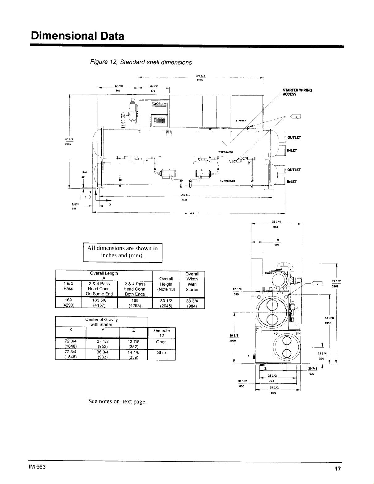
Page 17
Page 18

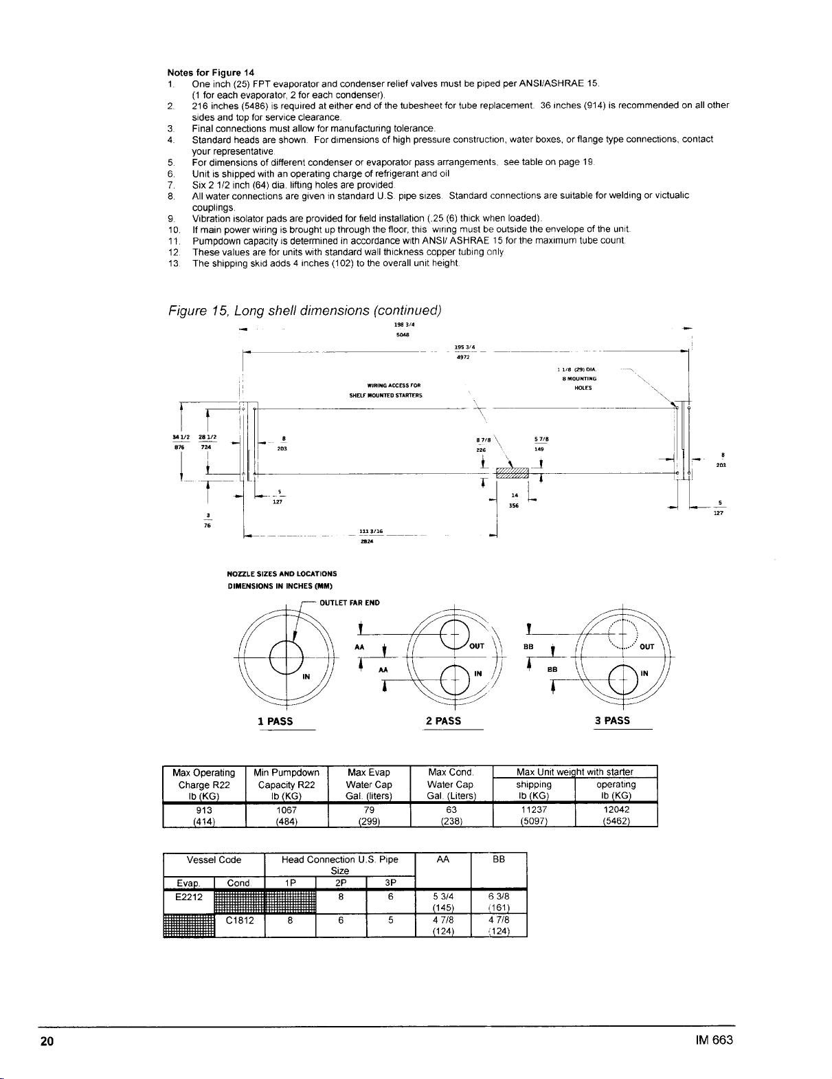
Page 19

Page 20
Page 21
Field Wiring
PFS unit compressors are single direction rotation compressors. For this reason proper
phasing of electrical power is essential. Electrical phasing must be A, B, C clockwise for
electrical phases
power connection and includes one MotorSaver phase failure, phase reversal protective
device that will prevent operation of the unit with incorrect power phasing. The MotorSaver is
factory wired and tested. Do not alter the wiring to the
General Information
Wiring
accordance with specifications.
Copper wire must be used for all wiring
CAUtlON
1,
2 and 3 (A=L1
must
comply with all applicable codes and ordinances. Warranty is void
,B=L2,C=L3)
The unit is supplied with single point factory
MotorSaver.
if wiring
is not in
The PFS is supplied standard with the main power
large power terminal block is provided. Wiring within the unit is sized according to the National
Electrical Code. A single field-mounted disconnect (supplied by others) is required. An optional
factory mounted transformer for the
Main power must enter the control panel at the location indicated on the unit illustration.
1
15
volt control circuit may have been provided.
wiring for single point power connection. A single
IM
663
21
Page 22

Page 23

Page 24

Page 25

Pre-Start-up
1.
Open all electrical disconnects and check electrical connections are tight.
2.
Verify water piping flow directions are correct and properly connected at the evaporator and
condenser.
3.
Using a phase tester,
4.
Verify unit power supply is within
5.
Verify power supply wiring is the correct size and has a minimum temperature insulation rating of
75°C.
6.
Verify all mechanical and electrical inspections have been completed according to local code.
7.
Make certain all
available.
Check all compressor valve connections for tightness.
8.
Open compressor suction valve until backseated. (This is an optional valve)
9.
Open discharge shutoff valve until backseated
10.
I 1.
Vent air from the evaporator and condenser water system piping.
12.
Open all water tlow valves and start chilled water pump.
13.
Check all piping for leaks.
14.
Flush the evaporator and condenser system piping.
verify
auxilliary
electrical phasing is A-B-C clockwise (A=L I, B=L2.C=L3).
10% of nameplate rating.
control equipment is operative and an adequate cooling load is
Sequence of Operation
The following sequence of operation is typical for McQuay models PFS
rotary screw water chillers. The sequence may vary depending on the software revision or various
options that may be installed on the chiller.
Initial Conditions
Before energizing the control box do the following:
1.
Verify the two control circuits are powered through the primary fuses FU1 and
secondary fuse
2.
Verify
the power developed through the transformer CPT in the starter is 120 Vac on the
secondary.
3.
Verify front panel switch is in the off position.
When applying power to the control for the first time do the following:
1.
Open the left door and the top door to each control box.
2.
Observe when power is applied the display lights up and when the Unit Status screen appears the
EXV board lights rapidly sequence closed.
3.
Listen for the stepper motors closing with a ratcheting sound.
FU3.
150B
through
FU2
PFS2 15B
and the
IM 663
25
Page 26

4. The Unit Status Screen on the display should indicate Off: Front Panel SW.
5. Verify the control setup for the network of two control boxes as follows:
*** 1s unit Model size
Move Master control communication connector fi-oni B to A port and disconnect the RSX2
connector (the one with the juniper from pin 2 - pin 6)
Second Screen Nevt Item
Slave Address
Mode= Auto:Local Auto- Network
Note. If address switches were changed then reset power off / on for both boxes
Off Conditions
With power to the controller there are several “off’ states as follows:
Off: Manual When the setpoint in menu “I I Control Mode” is set to the Mode= Manual Off to
change set the Mode= Auto: Network or any other running mode.
Off: Front Panel SW When the panel switch is in the “Stop” position. To change move the switch
to “Auto” position.
Off Alarm Remove the alarm state then clear the alarm to remove this off state.
Alarm
The alarm light on the front panel illuminates when the particular control receives an active alarm
state. That particular control will be locked out of compressor start or operation. The other control
will still be able to start.
26 IM 663
Page 27

Initial Start-up
CAUTION
Initial start-up must be performed by McQuayService personnel.
Set up control as described in the initial conditions.
1.
Turn front panel switch to Auto position (chilled water flow pump relay will energize).
2.
If the field installed flow indicator does not indicate chilled water flow after 30 seconds, the
3.
alarm output wi
The chiller
4.
The controller starts the compressor W ith
5.
the liquid in_jection solenoid and motor coolin
solenoids. and
Suction
6.
The discharge superheat drops below
Absolute Pres. ratio is greater than I.2 ( Abs. Condenser Psia i Abs. Evaporator Psia)
The unit status moves from:
7.
EvapOn-Recirc
Solenoid to Running Min Amp Lim to Running:
If additional cooling capacity is required then the controllers will add capacity by changing the
capacity control solenoids outputs 7. 8. and 9 and maintaining a close balance in amp capacity
between compressors after both compressor are running. The lag compressor will come on after the
lead compressor amps have exceeded the
23 on the master controller).
I l be
will
start w
injection
energized.
hen
the leaving
de-energizes
will turn
**Sec
the
off when
to All Systems Off to MCR Started to Pre-purge to Open
water
temperature is
the
least
starts
g
solenoid. energizes the suction
crank
case
heaters.
the following conditions have been met:
r
“F. the Liquid Presence sensor shows liquid, and the
3
setpoint
to turn on the lag for the defined lag time (see menu
3’F
above the Active Setpoint.
while in auto Iead-lag setting. energizes
%
Cap 50
injection
I
I
Load Recycle
As the load drops. the controls will unload the compressors until the compressors amps drop below
the lag cutoff point for the delay time required. The control will then shut off the lag compressor and
further reduction in load will cause the leaving water ternperature to drop 3
setpoint which will cause the compressor to turn off on Load Recycle and the display will show
Waiting For Load and the chilled water pump will remain on.
’
F below the active
IM
663
27
 Loading...