

Page 1
Installation Manual
Water-Cooled Dual Compressor Screw Chiller
Installation Manual
PFS 155C through PFS 210C, R-22
PFS 235C through PFS 315C, R-410A
60 Hertz
IM 692-1
Group: Chiller
Part Number: 629955
Effective: May 1997
Supersedes: IM663-1
IM683
IM692
© 1997 McQuay International
Page 2

Table of Contents
Introduction........................................................................................................... 3
Receiving and Handling...............................................................................................................3
Installation ............................................................................................................. 4
Location and Mounting................................................................................................................4
Compressor Condensation............................................................................................................4
Vibration Isolators .......................................................................................................................4
Evaporator and Condenser Water Piping ......................................................................................7
Water treatment ...........................................................................................................................7
Head pressure control, tower system.............................................................................................7
Head pressure control, well water system .....................................................................................8
Relief Valve Piping ......................................................................................................................8
Temperature and Water Flow Limitations.....................................................................................9
Evaporator Freeze Protection .......................................................................................................9
Condenser Protection and Design Considerations.........................................................................9
Chilled Water Thermostat............................................................................................................ 9
Refrigerant Charge ......................................................................................................................9
Detection of Loss of Flow...........................................................................................................10
Glycol Solutions.........................................................................................................................10
Evaporator and Condenser Water Flow and Pressure Drop..............................12
Physical Data........................................................................................................27
Dimensional Data.................................................................................................30
Field Wiring.........................................................................................................44
General Information ..................................................................................................................44
Pre-Start-up .........................................................................................................51
Sequence of Operation .........................................................................................51
Initial Conditions .......................................................................................................................51
Off Conditions...........................................................................................................................52
Alarm........................................................................................................................................52
Initial Start-up...........................................................................................................................52
Load Recycle .............................................................................................................................53
2 PFS 155C - 315C IM 692-1
Page 3
Introduction
McQuay StarGate™ water-cooled chillers are completely assembled, factory wired, evacuated,
charged, tested and ready for installation. Each unit consists of a water-cooled condenser with
integral subcooler, twin accessible semi-hermetic single screw compressors, replaceable tube shelland-tube evaporator, and complete refrigerant piping. Liquid line components included are manual
liquid line shutoff valves, charging valves, filter-dryers, liquid line solenoid valves,
sightglass/moisture indicators, and electronic expansion valves. Other features include compressor
heaters, and an advanced fully integrated microprocessor control system.
automatic operation, (the high and low pressure controls are external from the electrical control
center). Compressors are protected by solid-state overload protection and over temperature
protection. Field installed fused disconnect switch (furnished by others) offers additional protection.
Receiving and Handling
Inspect the unit immediately after receipt for possible damage. The unit is shipped FOB factory and
all claims for handling and shipping damage are the responsibility of the consignee. Leave the
shipping skid in place until the unit is in final position. This will aid in handling the equipment.
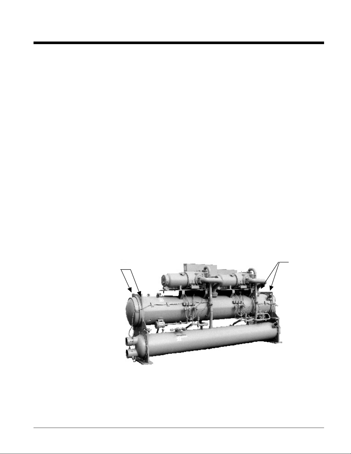
Use extreme care when rigging the equipment to prevent damage to the control center, or refrigerant
piping. See Dimensional Data for the center of gravity of the unit.
rigging eyes are located (see Figure 1). Use spreader bars between the rigging lines to prevent
damage to the control center.
The electrical control center includes all safety and operating controls necessary for dependable
Lift the unit by fastening the rigging hooks to the four corners of the evaporator where the
Figure 1, Rigging Eyes
Rigging Eyes
Rigging Eyes
IM 692-1 PFS 155C - 315C 3
Page 4

Installation
CAUTION
Installation must be performed by qualified personnel who are familiar with local codes,
regulations, and experienced with this type of equipment
Start-up by McQuayService is included on all units sold for installation within North America
excluding Mexico. Two weeks prior notification of start-up is required. The contractor should
obtain a copy of the Start-up Scheduled Request Form from the sales representative or from the
nearest McQuayService office.
Location and Mounting
Mount the unit on level concrete or steel base. Service clearance (at either end of the unit) is 12 feet
for units with 10 feet long shells, 14 feet for units with 12-feet long shells and 16 feet for units with
14 feet long shells. Evaporator and condenser tubes are rolled into the tube sheets to permit
replacement. Clearance at all other points, including the top, is 3 feet.
Make certain the floor or structural support is adequate to support the full operating weight of
the complete unit. Optional rubber-in-shear pads, or spring isolators can be ordered for use under
each corner of the base members. It is not necessary to bolt the unit to the mounting slab or frame
work; although mounting holes are provided in the unit support at the four corners.
Compressor Condensation
Condensation occurs on the compressor surface when the temperature of the compressor surface is
lower than the ambient dew point temperature. Drain pans with drain connections are provided
underneath each compressor to collect the condensate. The compressor motor housing extends past
the drain pans. Install a floor drain close to the unit to collect condensate from motor housing and
condensate pans.
Vibration Isolators
Optional vibration isolator pads are shipped with the unit for field installation. These pads provide
minimal isolation. Vibration isolators are recommended on all upper level installations where
vibration transmission is a consideration. When vibration isolators are used, install springs under
the main unit supports. Adjust spring so the upper housing clears lower housing by at least 1/4”
(6mm) and not more than 1/2” (1 3mm). If hold-down bolts are not used, install a rubber anti-skid
under isolators. Install vibration eliminators in water piping to reduce piping strain, vibration, and
noise. Table 1 lists spring and rubber-in-shear isolators for all PFS unit sizes.
4 PFS 155C - 315C IM 692-1
Page 5
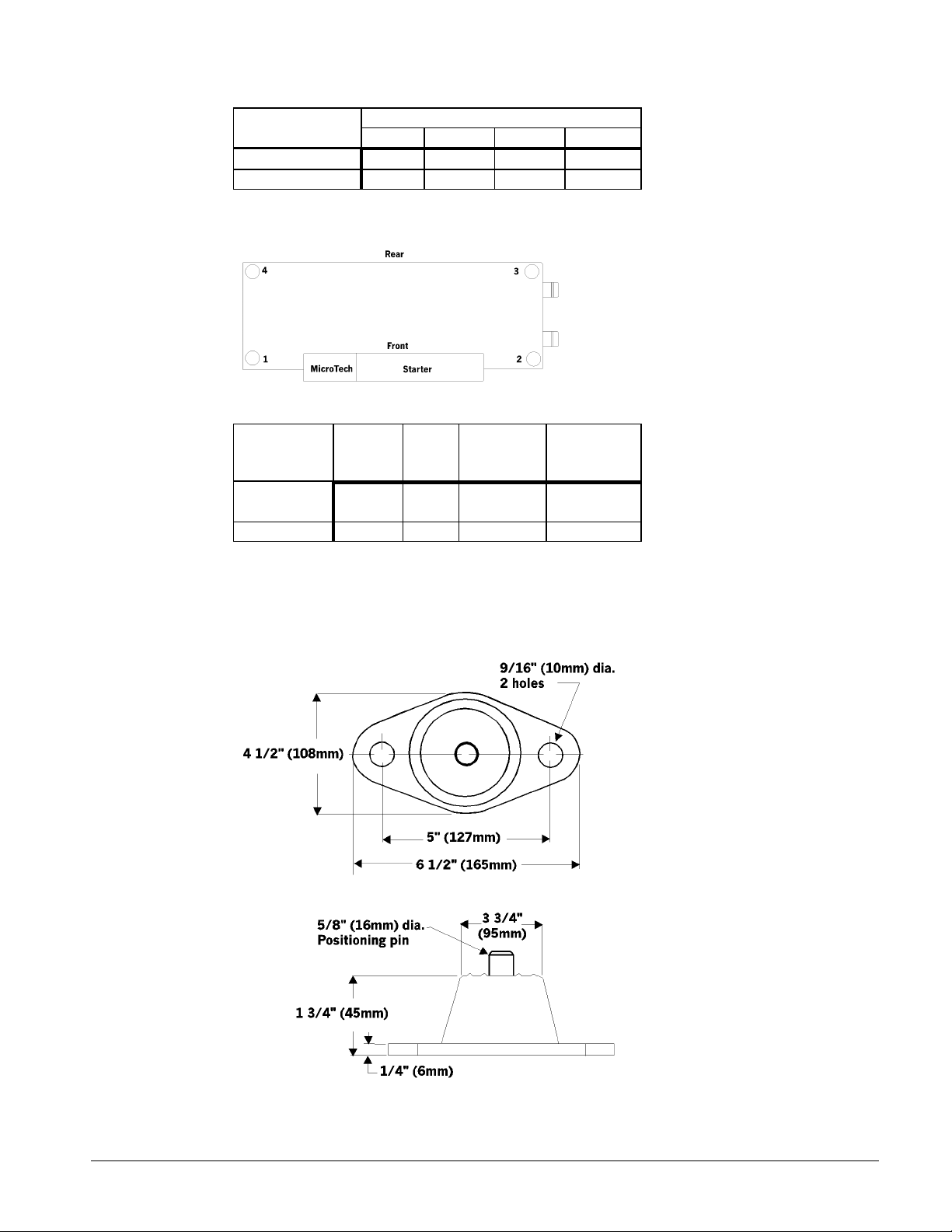
Table 1, Vibration Isolators (PFS150B - 215B)
Isolator Isolator Per Location
1 2 3 4
Rubber-in-Shear
Spring
RP-4 RP-4 RP-4 RP-4
CP-4-28 CP-4-28 CP-4-28 CP-4-28
Figure 2, Isolator location
Table 2, Isolators (PFS150B - 215B)
Color Recom.
Isolator Type Of McQuay Max Ld
Stripe Part No. Lb. (Kg)
Rubber-In-
Shear
Spring CP-4-28 Green 0058051328 3600 (1633)
Note: The spring is fully compressed at about 5400 lb (2449 Kg).
RP-4 Green 0021639803 3300 (1497)
Figure 3 and Figure 4 give dimensions required to secure each McQuay isolator section to the
mounting surface. The maximum loads for each unit are shown in Table 3.
Figure 3 , Rubber-in-Shear Isolator
IM 692-1 PFS 155C - 315C 5
Page 6
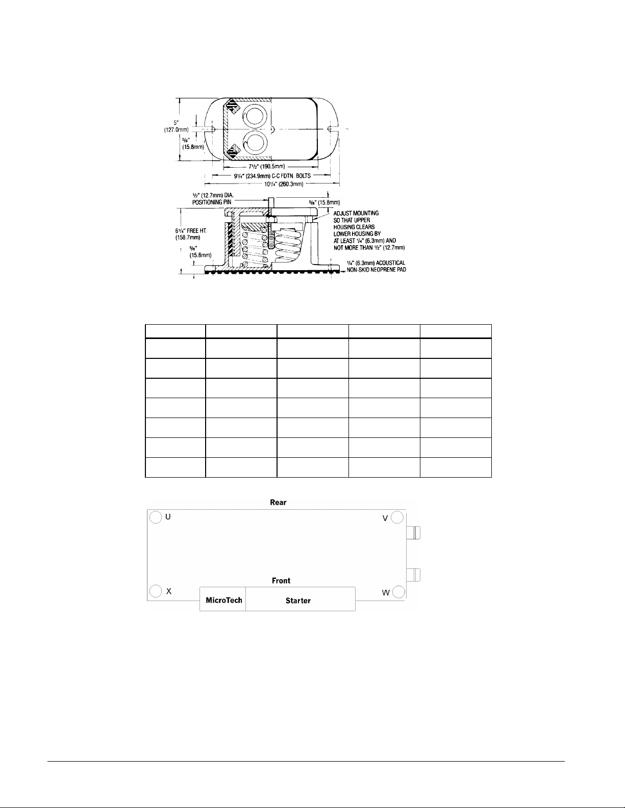
Figure 4,Spring Flex Isolator
Table 3, Weights for Standard Shell Units
Unit U X V W
155-210
Short Shell
235-315
Short Shell
155-210
Standard Shell
235-315
Standard Shell
155-190
Long Shell
200,210
Long Shell
235-315
Long Shell
2007 2412 2213 2660
2292 2841 2498 3095
2105 2475 2477 2913
2564 3060 2935 3501
3236 3107 3819 3667
2988 3182 3339 3556
3153 3468 3480 3827
Figure 5, Corner Weight Locations
6 PFS 155C - 315C IM 692-1
Page 7
Evaporator and Condenser Water Piping
PFS evaporators and condensers are equipped with either victaulic or flange connections. The
installing contractor must provide matching connections.
CAUTION
Remove the solid-state temperature sensor and thermostat bulbs from the wells to prevent
damage to those components when welding on the victaulic or flange connections.
Connect the condenser with the inlet water entering at the bottom to maximize subcooling. The
condenser water will discharge from the top connection.
Support piping to reduce weight and strain on the fittings and connections. Be sure piping is
adequately insulated. Install a cleanable 20-mesh water strainer in evaporator and condenser water
piping. Install enough shutoff valves to permit draining water from the evaporator or condenser
without draining the complete system.
CAUTION
Freeze Notice: The evaporator and condenser are not self-draining. Both must be blown
out.
Include thermometers at the inlet and outlet connections and air vents at the high points of piping.
The water heads can be interchanged (end for end) allowing water connections to be made at either
end of the unit. Use new head gaskets when interchanging water heads. When water pump noise
is objectionable, use rubber isolation sections at both the inlet and outlet of the pump. Vibration
eliminator sections in the condenser inlet and outlet water lines are not normally required. Where
noise and vibration are critical, and unit is mounted on spring isolators, flexible piping connections
are necessary.
Water treatment
If unit is operating with a cooling tower, clean and flush cooling tower. Make sure tower
"blowdown" or bleedoff is operating. Atmospheric air contains many contaminants which increases
the need for water treatment. The use of untreated water may result in corrosion, erosion, sliming,
scaling, or algae formation. A water treatment service is recommended. McQuay International is
not responsible for damage or faulty operation from untreated or improperly treated water.
Head pressure control, tower system
The minimum entering water temperature to the condenser must not be lower than 70°F (21.1°C) at
full tower water flow. If lower temperature water is used, the flow must be reduced proportionally.
Use a three-way bypass valve around the tower to modulate the condenser water flow. Figure 6
shows a three-way pressure actuator water regulating valve used for cooling applications. This
regulating valve will assure an adequate condensing pressure if the inlet condenser water
temperature falls below 70°F). An optional AOX-4 board located in the MicroTech panel will
control a cooling tower bypass valve or a varible speed condenser pump.
IM 692-1 PFS 155C - 315C 7
Page 8
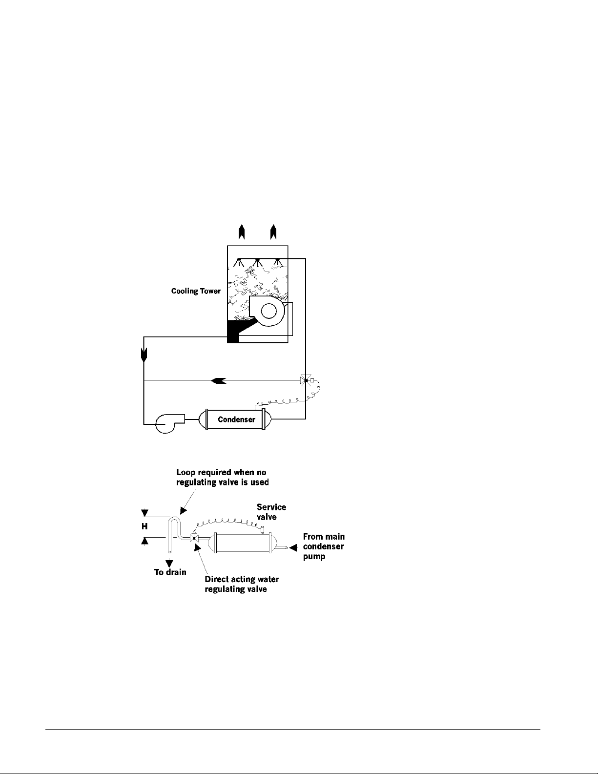
Head Pressure Control, Well Water System
When using city or well water for condensing refrigerant, install a normally closed direct acting
water regulating valve in the outlet piping of the condenser. This regulating valve will assure an
adequate condensing pressure if the inlet condenser water temperature falls below 70°F. The
condenser service valve provides a pressure tap for the regulating valve. The valve can modulate in
response to head pressure. On shutdown, the valve closes, preventing water from siphoning out of
the condenser. Siphoning causes condenser waterside drying and accelerates fouling. If a valve is
not used, Figure 7 illustrates the recommendation of a loop at the outlet. Size the loop height (H) to
offset the negative pressure caused by the siphoning effect. A vacuum breaker may be required.
Figure 6, Bypass valve
Figure 7, Well Water System
Relief Valve Piping
Follow the requirements of ANSI/ASHRAE Standard 15-1994 for relief valve piping. The
condenser relief valve assembly consists of a tree valve and two relief valves. The tree valve must
be fully front or back seated to ensure only one relief valve is available for discharge.
8 PFS 155C - 315C IM 692-1
Page 9

Temperature and Water Flow Limitations
PFS units are designed to operate in conditions from 20°F (-6.7°C) to 50°F (10°C) leaving water
temperature on the evaporator side and 70°F (21.1°C) to 95°F (35°C) entering water temperature on
the condenser side.
Glycol in the evaporator is required on all applications below 40°F (4.4°C) leaving evaporator
fluid temperature. The maximum allowable water temperature to the cooler in a non-operating
cycle is 105°F (40.6°C). The non-operating leaving condenser water temperature maximum is
115°F (46.1°C). Flow rates below the minimum values shown in the evaporator and condenser
pressure drop curves may cause freeze-up problems, scaling and poor control. Flow rates above the
maximum values shown in the evaporator and condenser pressure drop curves will result in
unacceptable pressure drops, excessive nozzle and tube erosion and possibly cause tube failure.
Evaporator Freeze Protection
When freeze protection is a concern, do the following:
1. If the unit will not be operated during the winter, drain and flush the evaporator and chilled
water piping with glycol . Drain and vent connections are provided on the evaporator.
2. When using a cooling tower, add glycol solution to the chilled water system. Freeze point
should be approximately 10°F (5.6°C) below minimum design ambient temperature.
Note: Freeze damage is not considered a warranty failure and is not the responsibility of
McQuay International.
3. Insulate field water piping, especially on the chilled water side.
Condenser Protection and Design Considerations
If pond or river water is used as a condensing medium and the water valves leak, the condenser and
liquid line refrigerant temperature could drop below the equipment room temperature on the "off"
cycle. This problem occurs when cold water continues to circulate through the condenser and the
unit remains off due to satisfied cooling load. If this occurs:
1. Cycle the condenser pump off with the unit.
2. Verify the liquid line solenoid valves are operating properly.
Chilled Water Thermostat
The PFS water-cooled chiller is equipped with the MicroTech leaving water controller. Be careful
when working around the unit to avoid damaging lead wires and sensor cables. Check lead wires
before running the unit. Avoid rubbing the lead wires on the frame or other components. Verify the
lead wires are firmly anchored. If the sensor is removed from the well for servicing, do not wipe off
the heat conducting compound supplied in the well.
Refrigerant Charge
All units are designed for use with R-22 or R-410A and are shipped with a full operating charge.
The operating charge for each unit is shown in the Physical Data Table.
IM 692-1 PFS 155C - 315C 9
Page 10
Detection of Loss of Flow
NOTE: Water pressure differential switches are not recommended for outdoor applications.
The preferred means for detecting loss of flow is the use of factory-mounted pressure differential
switches for the evaporator and condenser.
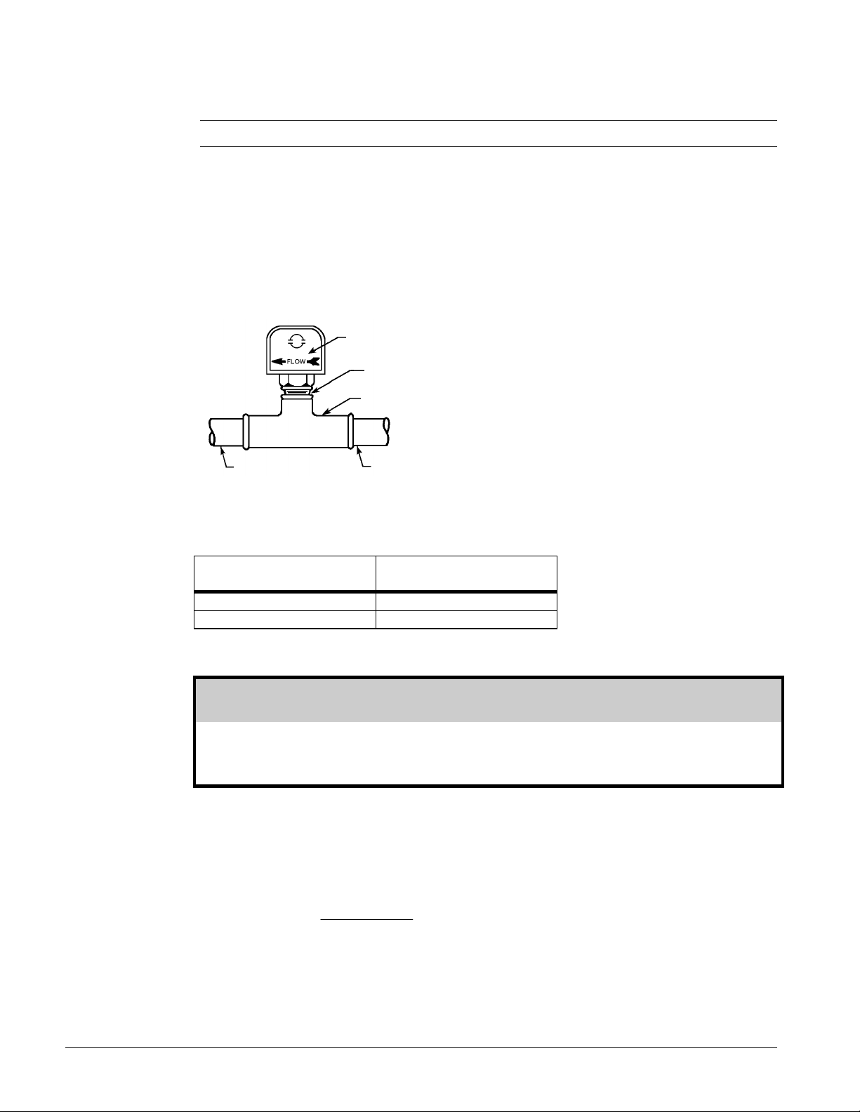
A flow switch is available from McQuay (part number 00175033-00). It is a “paddle” type
switch and adaptable to any pipe size from 3” (76mm) to 8” (203mm) nominal. Two flow switches
are required. Mount the flow switch in either the entering or leaving water line of the evaporator
and condenser. Certain minimum flow rates are required to close the switch and are listed in Table
4. Installation should be as shown in Figure 8.
Figure 8, Flow Switch
Flow direction
marked on
switch
1" (25mm) NPT
Tee
Note: The procedure
does not specify the
type of glycol. Use
the derate factors
found in Table 5 for
corrections when
using ethylene glycol
and those in Table 6
for propylene glycol.
5" (127mm)
5" (127mm)
Connect the normally open contacts of the flow switch in the unit control center at terminals 62
and 63. Flow switch contact must be suitable for 24 VAC, low current (16ma).
Table 4, Flow Switch Minimum Flow Rates
Nominal Pipe Size Min. Required Flow to
(inches) Activate Switch - GPM (L/s)
5 58.7 (3.7)
6 79.2 (5)
Glycol Solutions
CAUTION
Use industrial grade glycols only. Do not use an automotive grade antifreeze. Automotive
antifreeze contains inhibitors that will cause plating on the copper tubes within the chiller
evaporator. The type and handling of glycol used must be consistent with local codes.
To determine flow rate for the evaporator in GPM (L/s), and pressure drop through the cooler, use
the following formulas and tables.
1. Capacity - Multiply the chiller's capacity with water by the capacity correction factor (Cap) to
find the chiller's capacity with glycol.
2. GPM - To determine evaporator GPM (or Delta-T) knowing Delta-T (or GPM) and tons:
24 ×
tons glycol
Glycol GPM = (from table)
( )
−
Delta T
×
flow
10 PFS 155C - 315C IM 692-1
Page 11
For metric applications:
L/s - To determine evaporator L/s (or Delta-T) knowing Delta-T (or L/s) and kW:
Glycol L / s = (from table)
kW
Delta T
418. × −
flow
×
3. Pressure Drop - To determine pressure drop through the cooler when using glycol, enter the
appropriate water pressure drop curve (begin on page 12 at the actual glycol flow. Multiply the
water pressure drop found there by pressure drop adjustment factor (PD) to obtain corrected
glycol pressure drop.
4. To determine the unit power consumption, multiply the unit kW/TR with water by the (kW/TR)
factor. Test coolant with a clean, accurate glycol solution hydrometer (similar to that found in
service stations) to determine the freezing point. Obtain percent glycol from the freezing point
table below. A minimum of 25% solution by weight should be used for protection against
corrosion.
Note: The effect of glycol in the condenser is negligible. As glycol increases in
temperature, its properties approach those of water. For selection purposes, there is no
derate in capacity for glycol in the condenser.
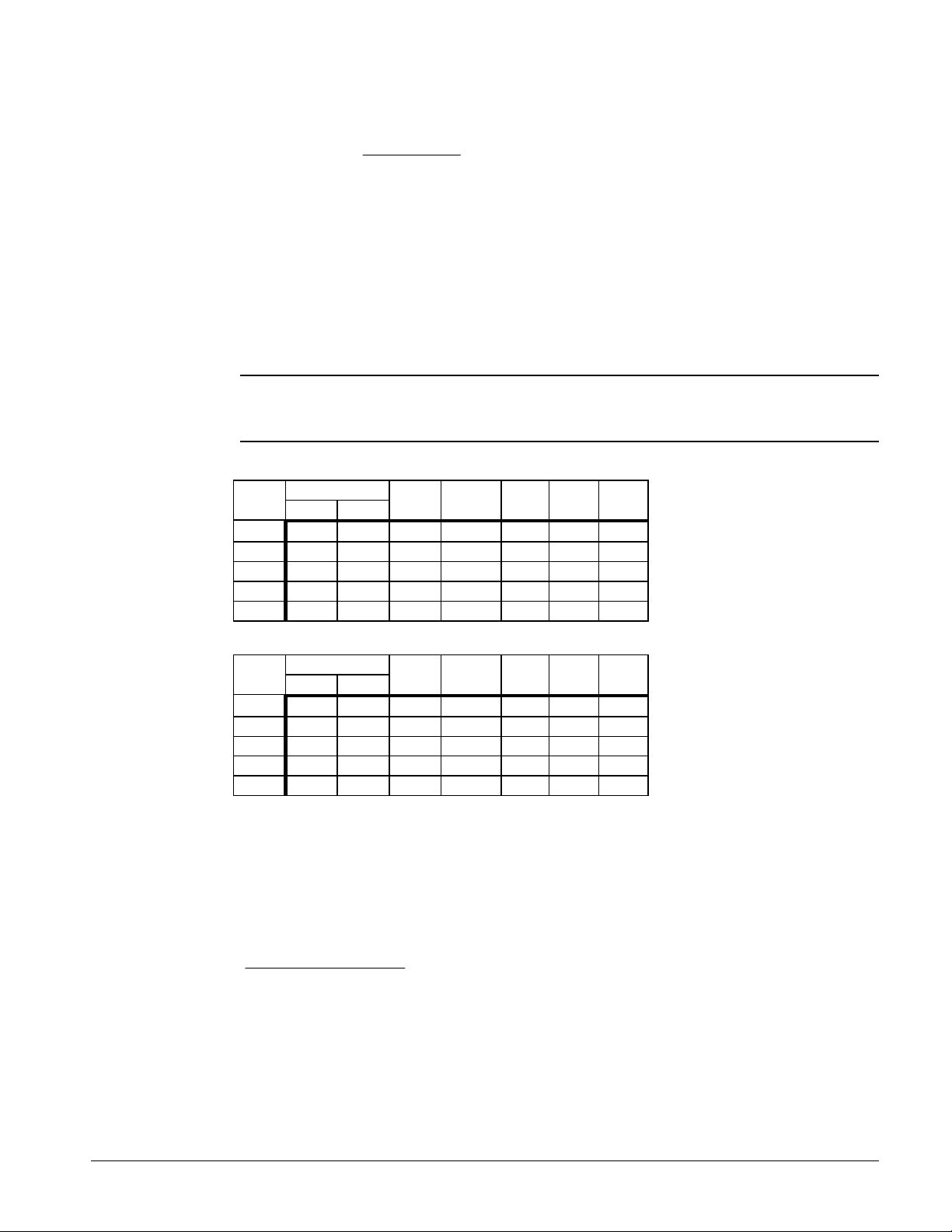
Table 5, Adjustment factors for ethylene glycol
% Freeze Point
E.G. °F °C CAP. kW/TR COP Flow PD
10 26 -3 0.991 1.005 0.995 1.013 1.070
20 18 -8 0.982 1.010 0.990 1.040 1.129
30 7 -14 0.972 1.014 0.986 1.074 1.181
40 -7 -22 0.961 1.016 0.984 1.121 1.263
50 -28 -33 0.946 1.021 0.979 1.178 1.308
Table 6, Adjustment factors for propylene glycol
% Freeze Point
P.G. °F °C CAP. kW/TR COP Flow PD
10 26 -3 0.987 1.005 0.995 1.010 1.068
20 19 -7 0.975 1.010 0.990 1.028 1.147
30 9 -13 0.962 1.017 0.983 1.050 1.248
40 -5 -21 0.946 1.026 0.975 1.078 1.366
50 -27 -33 0.929 1.039 0.962 1.116 1.481
Application Considerations
The chilled water loop must contain an adequate volume of water to prevent short cycling the
chiller. Minimum water volume can be determined using the following formula:
Design GPM X 15 Minutes
Number of Compressors
Volume of Water=
IM 692-1 PFS 155C - 315C 11
Page 12
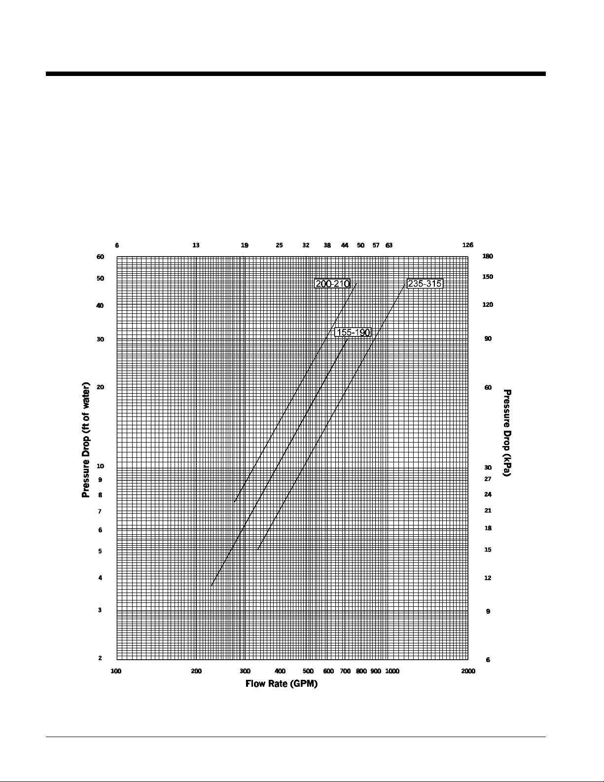
Evaporator and Condenser Water Flow and Pressure Drop
Flow rates must fall between the minimum and maximum values shown on the appropriate
evaporator and condenser curves. Flow rates below the minimum values shown will result in
laminar flow that will reduce efficiency, cause erratic operation of the electronic expansion valve
and could cause low temperature cutouts. Flow rates exceeding the maximum values shown can
cause erosion on the evaporator water connections and tubes.
Measure the chilled water pressure drop through the evaporator at field installed pressure taps. It is
important not to include the effect of valves or strainers in these readings.
Do not vary the water flow through the evaporator while the compressor(s) are operating.
MicroTech control setpoints are based on constant flow.
Figure 9 , Evaporator 2-pass (short shell)
12 PFS 155C - 315C IM 692-1
Page 13
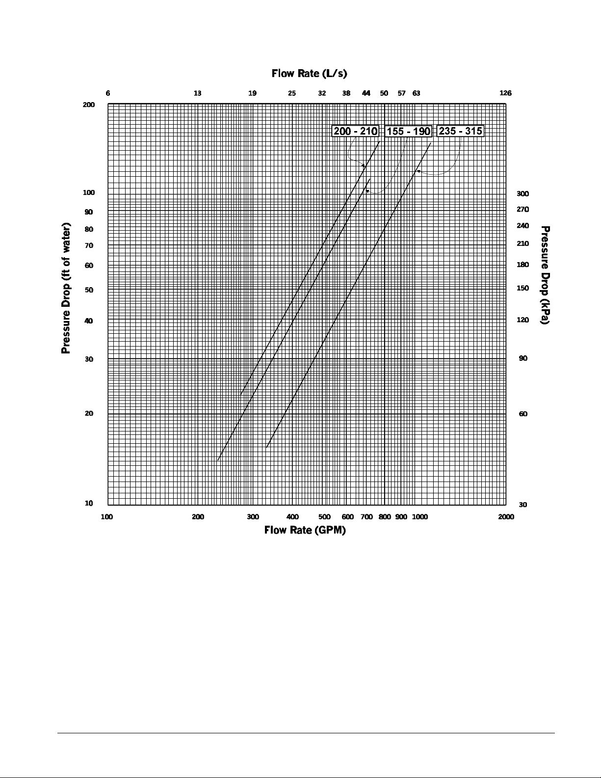
Figure 10, Evaporator 3-Pass (Short Shell)
IM 692-1 PFS 155C - 315C 13
Page 14
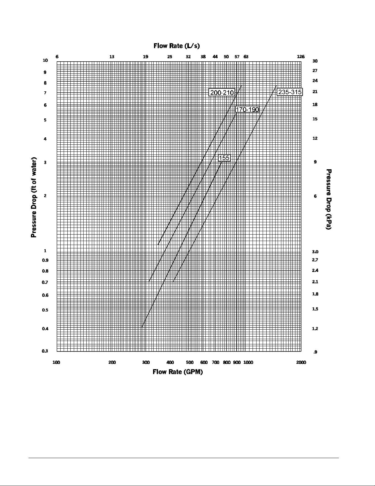
Figure 11, Condenser 1-Pass (Short Shell)
14 PFS 155C - 315C IM 692-1
Page 15
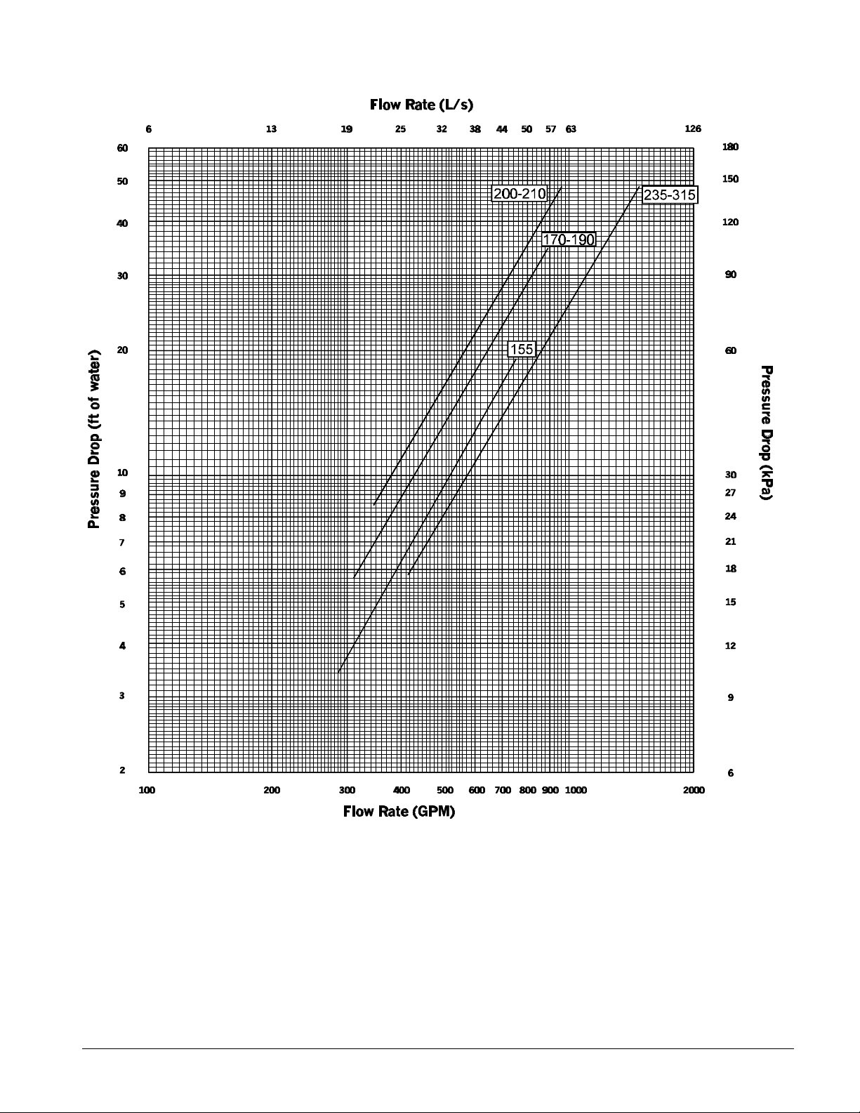
Figure 12, Condenser 2-Pass (Short Shell)
IM 692-1 PFS 155C - 315C 15
Page 16
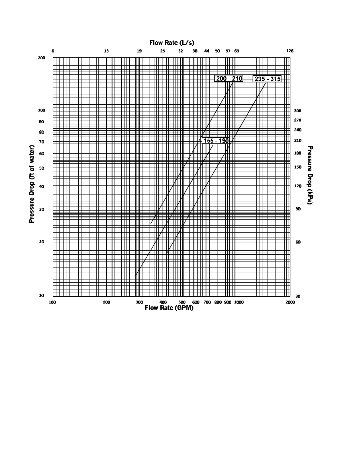
Figure 13, Condenser 3-Pass (Short Shell)
16 PFS 155C - 315C IM 692-1
Page 17
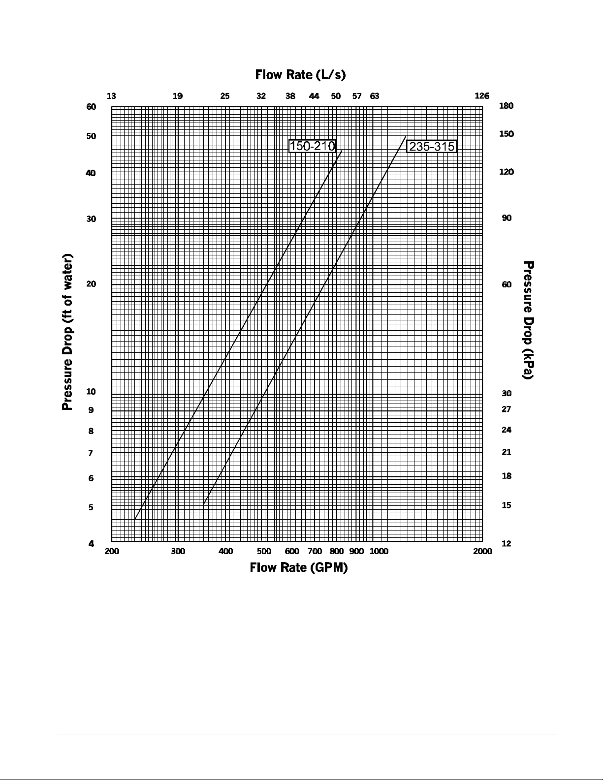
Figure 14, Evaporator 2-Pass (Standard Shell)
IM 692-1 PFS 155C - 315C 17
Page 18

Figure 15, Evaporator 3-Pass (Standard Shell)
18 PFS 155C - 315C IM 692-1
Page 19

Figure 16, Condenser 1-Pass (Standard Shell)
IM 692-1 PFS 155C - 315C 19
Page 20
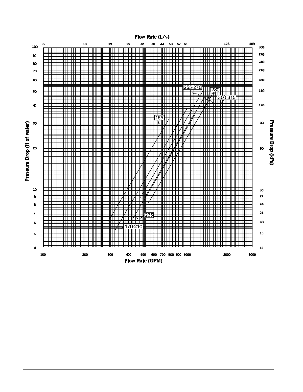
Figure 17, Condenser 2-Pass (Standard Shell)
20 PFS 155C - 315C IM 692-1
Page 21
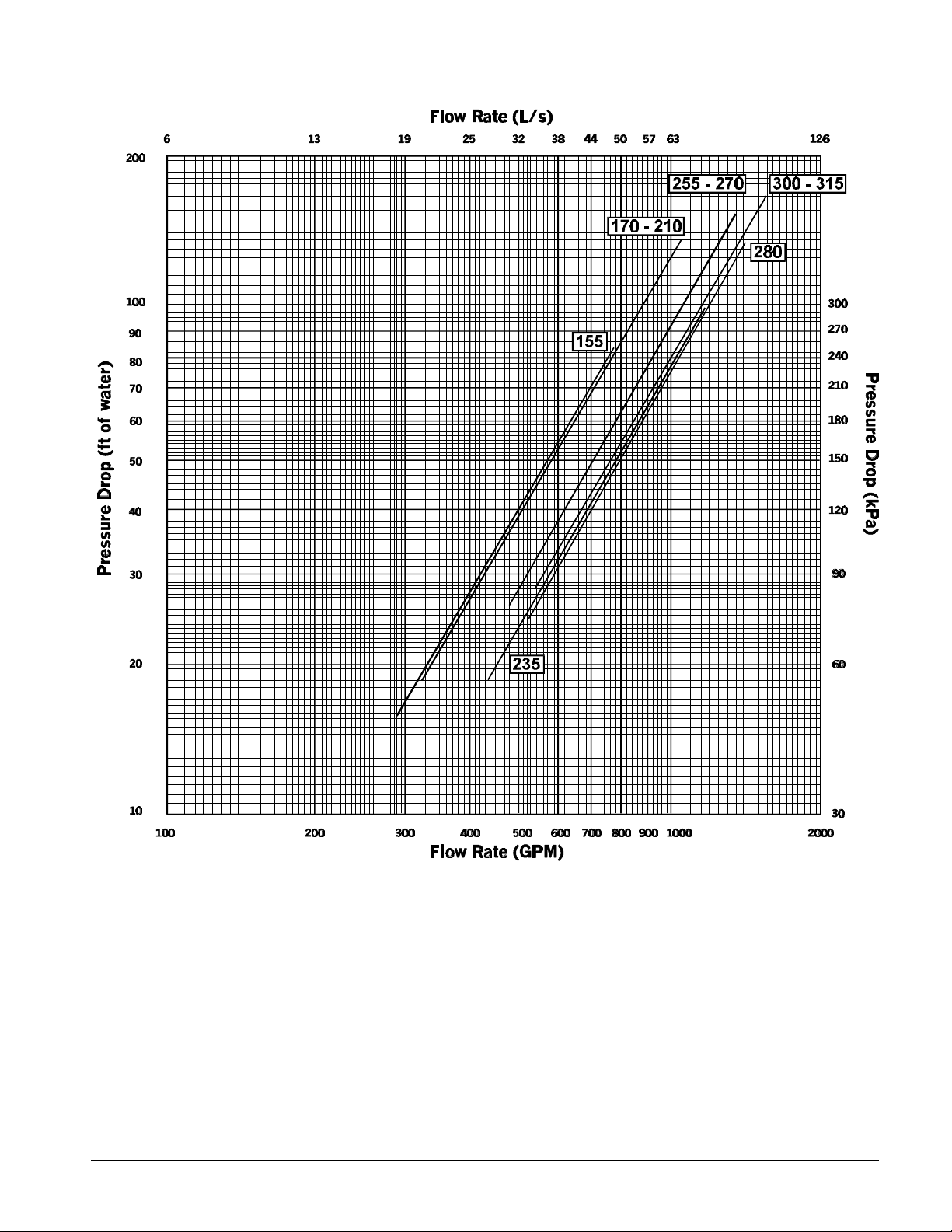
Figure 18, Condenser 3-Pass (Standard Shell)
IM 692-1 PFS 155C - 315C 21
Page 22
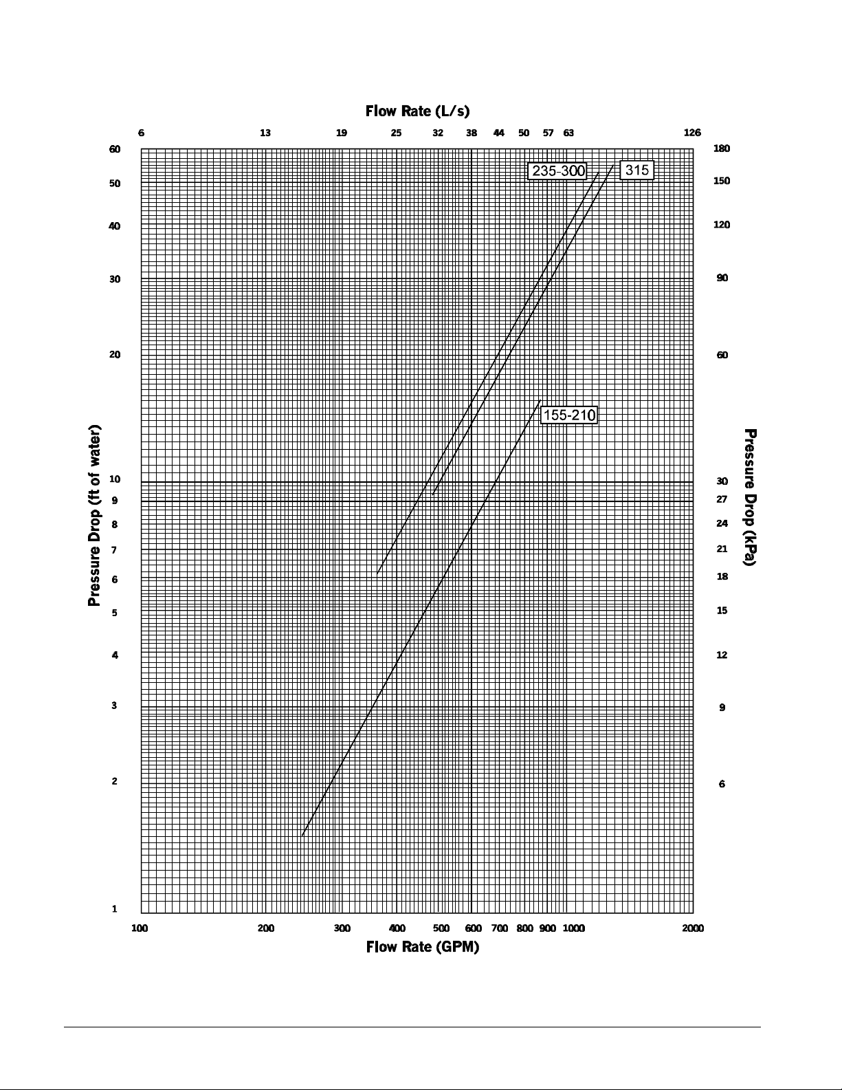
Figure 19, Evaporator 2-Pass (Long Shell)
22 PFS 155C - 315C IM 692-1
Page 23

Figure 20, Evaporator 3-Pass (Long Shell)
IM 692-1 PFS 155C - 315C 23
Page 24
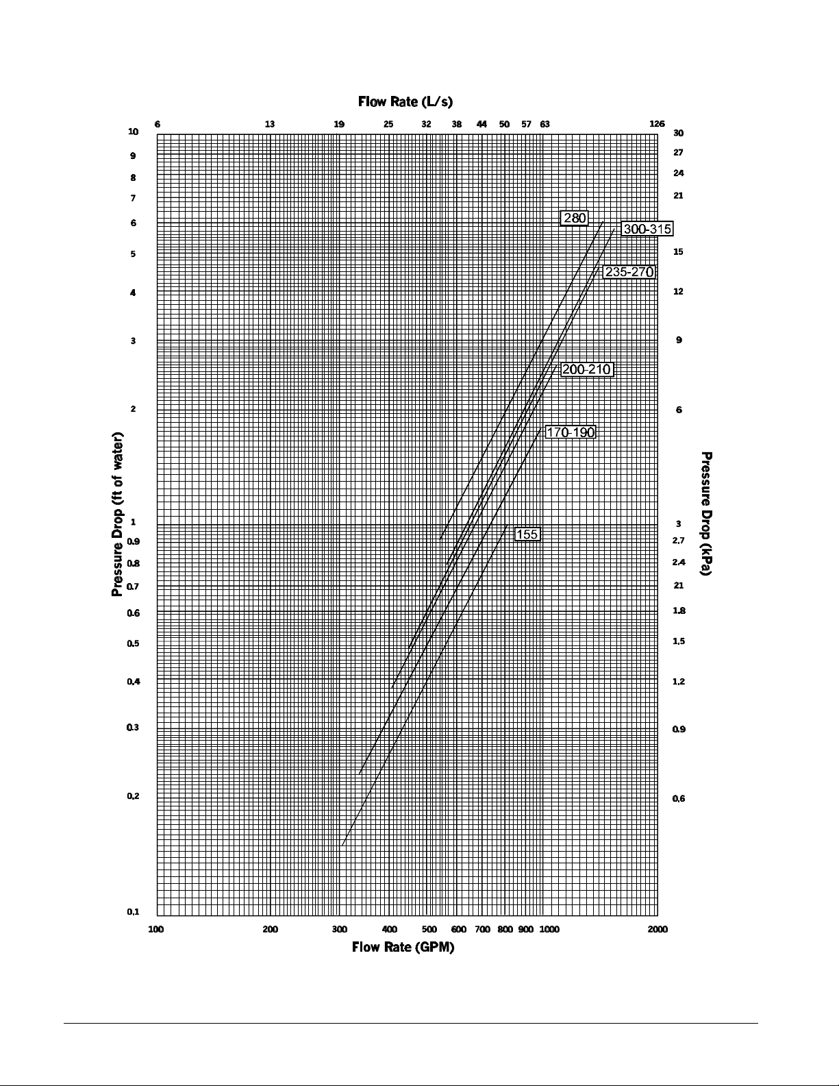
Figure 21, Condenser 1-Pass (Long Shell)
24 PFS 155C - 315C IM 692-1
Page 25
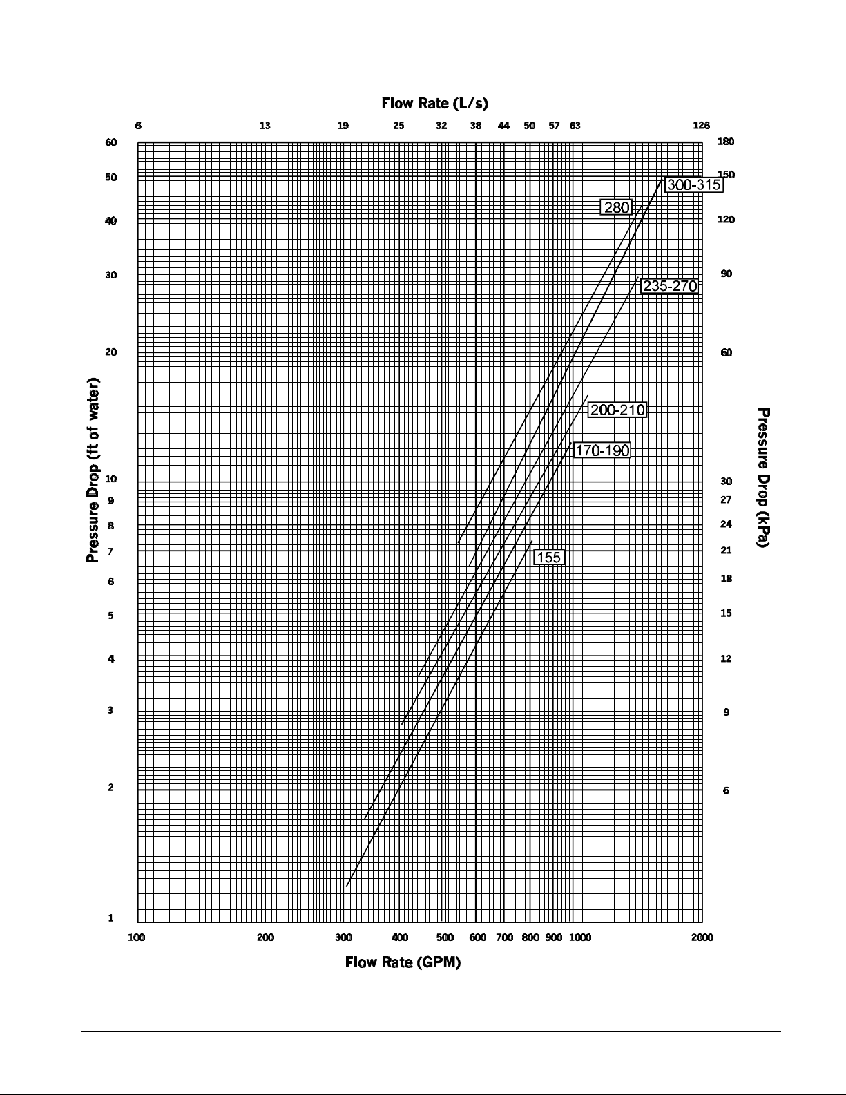
Figure 22,Condenser 2-Pass (Long Shell)
IM 692-1 PFS 155C - 315C 25
Page 26

Figure 23, Condenser 3-Pass (Long Shell)
26 PFS 155C - 315C IM 692-1
Page 27

Physical Data
Table 7, Physical Data, PFS 155C - PFS 210C
BASIC DATA
SHORT SHELL
Unit Capacity @ ARI Conditions,
Unit Operating Charge R-22, lb. (kg) 582 (264) 589 (267) 589 (267) 589 (267) 607 (276) 607 (276)
Min Pumpdown Capacity R-22, lb.
STANDARD SHELL
Unit Capacity @ ARI Conditions,
Unit Operating Charge R-22, lb. (kg) 661 (300) 653 (296) 653 (296) 653 (296) 653 (296) 653 (296)
Min Pumpdown Capacity R-22, lb.
LONG SHELL
Unit Capacity @ ARI Conditions,
Unit Operating Charge R-22, lb. (kg) 984 (447) 994 (451) 994 (451) 994 (451) 953 (433) 953 (433)
Min Pumpdown Capacity R-22, lb.
COMPRESSORS, SCREW, SEMI-HERMETIC
FLOODED EVAPORATOR - SHORT SHELL
Quantity, (Number of Water Passes) 1 (2) 1 (2) 1 (2) 1 (2) 1 (2) 1 (2)
Shell Diameter -- Tube Length 18 - 10 18 - 10 18 - 10 18 - 10 18 - 10 18 - 10
in. (mm) ft. (mm) (457 - 3048) (457 - 3048) (457 - 3048) (457 - 3048) (457 - 3048) (457 - 3048)
Max. Water Pressure, psi (kPa) 150 (1035) 150 (1035) 150 (1035) 150 (1035) 150 (1035) 150 (1035)
Max. Refrigerant Pressure, psi (kPa) 250 (1725) 250 (1725) 250 (1725) 250 (1725) 250 (1725) 250 (1725)
Water Connections (Victaulic),
CONDENSER - SHORT SHELL
Quantity, (Number of Water Passes) 1 (2) 1 (2) 1 (2) 1 (2) 1 (2) 1 (2)
Shell Diameter -- Tube Length 18 - 10 18 - 10 18 - 10 18 - 10 18 - 10 18 - 10
in. (mm) ft. (mm) (457 - 3048) (457 - 3048) (457 - 3048) (457 - 3048) (457 - 3048) (457 - 3048)
Max. Water Pressure, psi (kPa) 150 (1035) 150 (1035) 150 (1035) 150 (1035) 150 (1035) 150 (1035)
Max. Refrigerant Pressure, psi (kPa) 300 (2070) 300 (2070) 300 (2070) 300 (2070) 300 (2070) 300 (2070)
Water Connections (Victaulic),
Data 155C 170C 180C 190C 200C 210C
tons (kW)
(kg)
Cabinet Dimensions 139.75 x 42.0 x 76.88 139.75 x 42.0 x 76.88 139.75 x 42.0 x 76.88 139.75 x 42.0 x 76.88 139.75 x 42.0 x 76.88 139.75 x 42.0 x 76.88
L x W x H, in. (mm) 3550 x 1067 x 1953 3550 x 1067 x 1953 3550 x 1067 x 1953 3550 x 1067 x 1953 3550 x 1067 x 1953 3550 x 1067 x 1953
Operating Weight (with
starters),lb.(kg)
Shipping Weight, (with
starters),lb.(kg)
tons (kW)
(kg)
Cabinet Dimensions 162.75 x 42 x 76.88 162.75 x 42 x 76.88 162.75 x 42 x 76.88 162.75 x 42 x 76.88 162.75 x 42 x 76.88 162.75 x 42 x 76.88
L x W x H, in. (mm) 4134 x 1067 x 1953 4134 x 1067 x 1953 4134 x 1067 x 1953 4134 x 1067 x 1953 4134 x 1067 x 1953 4134 x 1067 x 1953
Operating Weight (with
starters),lb.(kg)
Shipping Weight, (with
starters),lb.(kg)
tons (kW)
(kg)
Cabinet Dimensions 164.6 x 50.9 x 86 164.6 x 50.9 x 86 164.6 x 50.9 x 86 164.6 x 50.9 x 86 164.6 x 48.4 x 80.4 164.6 x 48.4 x 80.4
L x W x H, in. (mm) 4180 x 1292 x 2184 4180 x 1292 x 2184 4180 x 1292 x 2184 4180 x 1292 x 2184 4180 x 1229 x 2042 4180 x 1229 x 2042
Operating Weight (with
starters),lb.(kg)
Shipping Weight, (with
starters),lb.(kg)
Nominal Tons, (kW) 70 (250) 70 (250) 70 (250) 85 (300) 70 (250) 100 (350) 85 (300) 85 (300) 85 (300) 100 (350) 100 (350) 100 (350)
Water Volume, gallons (L) 37.4 (142) 37.4 (142) 37.4 (142) 37.4 (142) 33.2 (126) 33.2 (126)
in (mm)
Water Volume, gallons (L) 45.5 (173) 40.1 (152) 40.1 (152) 40.1 (152) 36.8(140) 36.8 (140)
in (mm)
151.4 (532) 165.1 (581) 174.7 (614) 179.7 (632) 183.4 (645) 192.0 (675)
689 (313) 739 (336) 739 (336) 739 (336) 770 (350) 770 (350)
9292 (4214) 9292 (4214) 9292 (4214) 9292 (4214) 9292 (4214) 9292 (4214)
8978 (4072) 8978 (4072) 8978 (4072) 8978 (4072) 8978 (4072) 8978 (4072)
154.0 (542) 171.0 (601) 181.3 (638) 186.6 (656) 196.5 (691) 206.4 (726)
882 (400) 822 (373) 822 (373) 822 (373) 822 (373) 822 (373)
9970 (4522) 9970 (4522) 9970 (4522) 9970 (4522) 9970 (4522) 9970 (4522)
9567 (4339) 9567 (4339) 9567 (4339) 9567 (4339) 9567 (4339) 9567 (4339)
162.0 (570) 179.5 (631) 190.9 (671) 197.0 (693) 208.0 (731) 219.2 (771)
1399 (635) 1478 (671) 1478 (671) 1478 (671) 1174 (533) 1174 (533)
13829 (6272) 13829 (6272) 13829 (6272) 13829 (6272) 13065 (5925) 13065 (5925)
12651 (5737) 12651 (5737) 12651 (5737) 12651 (5737) 12037 (5459) 12037 (5459)
6 (152) 6 (152) 6 (152) 6 (152) 6 (152) 6 (152)
6 (152) 6 (152) 6 (152) 6 (152) 6 (152) 6 (152)
PFS Unit Size
Table 7, Physical Data continued on next page.
IM 692-1 PFS 155C - 315C 27
Page 28

Table 7, Physical Data, PFS 155C - PFS 210C (continued)
Data 155C 170C 180C 190C 200C 210C
BASIC DATA
FLOODED EVAPORATOR - STANDARD SHELL
Quantity, (Number of Water Passes) 1 (2) 1 (2) 1 (2) 1 (2) 1 (2) 1 (2)
Shell Diameter – Tube Length 18 - 12 18 - 12 18 - 12 18 - 12 18 - 12 18 - 12
in. (mm) ft. (mm) (457 - 3658) (457 - 3658) (457 - 3658) (457 - 3658) (457 - 3658) (457 - 3658)
Water Volume, gallons (L) 42 (160) 42 (160) 42 (160) 42 (160) 42 (160) 36.9 (140)
Max. Water Pressure, psi (kPa) 150 (1035) 150 (1035) 150 (1035) 150 (1035) 150 (1035) 150 (1035)
Max. Refrigerant Pressure, psi (kPa) 250 (1725) 250 (1725) 250 (1725) 250 (1725) 250 (1725) 250 (1725)
Water Connections (Victaulic), in
CONDENSER - STANDARD SHELL
Quantity, (Number of Water Passes) 1 (2) 1 (2) 1 (2) 1 (2) 1 (2) 1 (2)
Shell Diameter -- Tube Length 18 - 12 18 - 12 18 - 12 18 - 12 18 - 12 18 - 12
in. (mm) ft. (mm) (457 - 3658) (457 - 3658) (457 - 3658) (457 - 3658) (457 - 3658) (457 - 3658)
Max. Water Pressure, psi (kPa) 150 (1035) 150 (1035) 150 (1035) 150 (1035) 150 (1035) 150 (1035)
Max. Refrigerant Pressure, psi (kPa) 300 (2070) 300 (2070) 300 (2070) 300 (2070) 300 (2070) 300 (2070)
Water Connections (Victaulic), in
FLOODED EVAPORATOR - LONG SHELL
Quantity, (Number of Water Passes) 1 (2) 1 (2) 1 (2) 1 (2) 1 (2) 1 (2)
Shell Diameter -- Tube Length 24 - 12 24 - 12 24 - 12 24 - 12 24 - 12 24 - 12
in. (mm) ft. (mm) (610 - 3658) (610 - 3658) (610 - 3658) (610 - 3658) (610 - 3658) (610 - 3658)
Max. Water Pressure, psi (kPa) 150 (1035) 150 (1035) 150 (1035) 150 (1035) 150 (1035) 150 (1035)
Max. Refrigerant Pressure, psi (kPa) 250 (1725) 250 (1725) 250 (1725) 250 (1725) 250 (1725) 250 (1725)
Water Connections (Victaulic),
CONDENSER - LONG SHELL
Quantity, (Number of Water Passes) 1 (2) 1 (2) 1 (2) 1 (2) 1 (2) 1 (2)
Shell Diameter -- Tube Length 24 - 12 24 - 12 24 - 12 24 - 12 22 - 12 22 - 12
in. (mm) ft. (mm) (610 - 3658) (610 - 3658) (610 - 3658) (610 - 3658) (559 - 3658) (559 - 3658)
Max. Water Pressure, psi (kPa) 150 (1035) 150 (1035) 150 (1035) 150 (1035) 150 (1035) 150 (1035)
Max. Refrigerant Pressure, psi (kPa) 300 (2070) 300 (2070) 300 (2070) 300 (2070) 300 (2070) 300 (2070)
Water Connections (Victaulic),
(mm)
Water Volume, gallons (L) 45.2 (171) 51.6 (196) 51.6 (196) 51.6 (196) 51.6 (196) 45.2 (171)
(mm)
Water Volume, gallons (L) 81.8 (310) 81.8 (310) 81.8 (310) 81.8 (310) 81.8 (310) 81.8 (310)
in (mm)
Water Volume, gallons (L) 105.9 (401) 97.5 (369) 97.5 (369) 97.5 (369) 86.9 (329) 86.9 (329)
in (mm)
6 (152) 6 (152) 6 (152) 6 (152) 6 (152) 6 (152)
6 (152) 6 (152) 6 (152) 6 (152) 6 (152) 6 (152)
8 (204) 8 (204) 8 (204) 8 (204) 8 (204) 8 (204)
8 (204) 8 (204) 8 (204) 8 (204) 8 (204) 8 (204)
PFS Unit Size
Table 8, Physical Data, PFS 235C - PFS315C
BASIC DATA
SHORT SHELL
Unit Capacity @ ARI Conditions,
Unit Operating Charge R-410A,
Min Pumpdown Capacity R-410A,
STANDARD SHELL
Unit Capacity @ ARI Conditions,
Unit Operating Charge R-410A,
Min Pumpdown Capacity R-410A,
Data 235C 255C 270C 280C 300C 315C
tons (kW)
lb. (kg)
lb. (kg)
Cabinet Dimensions 140.75 x 43.9 x 84.25 140.75 x 43.9 x 84.25 140.75 x 43.9 x 84.25 140.75 x 43.9 x 84.25 140.75 x 43.9 x 84.25 140.75 x 43.9 x 84.25
L x W x H, in. (mm) 3575 x 1115 x 2140 3575 x 1115 x 2140 3575 x 1115 x 2140 3575 x 1115 x 2140 3575 x 1115 x 2140 3575 x 1115 x 2140
Operating Weight (with
starters),lb.(kg)
Shipping Weight, (with
starters),lb.(kg)
tons (kW)
lb. (kg)
lb. (kg)
Cabinet Dimensions 163.75 x 43.9 x 84.25 163.75 x 43.9 x 84.25 163.75 x 43.9 x 84.25 163.75 x 43.9 x 84.25 163.75 x 43.9 x 84.25 163.75 x 43.9 x 84.25
L x W x H, in. (mm) 4159 x 1115 x 2140 4159 x 1115 x 2140 4159 x 1115 x 2140 4159 x 1115 x 2140 4159 x 1115 x 2140 4159 x 1115 x 2140
Operating Weight (with
starters),lb.(kg)
Shipping Weight, (with
starters),lb.(kg)
222.3 (782) 243.7 (857) 257.4 (905) 264.6 (930) 278.6 (980) 292.0 (1027)
772 (350) 772 (350) 772 (350) 772 (350) 772 (350) 772 (350)
793 (360) 793 (360) 793 (360) 793 (360) 793 (360) 793 (360)
10726 (4864) 10726 (4864) 10726 (4864) 10726 (4864) 10726 (4864) 10726 (4864)
10185 (4619) 10185 (4619) 10185 (4619) 10185 (4619) 10185 (4619) 10185 (4619)
233.0 (819) 256.0 (900) 270.9 (953) 280.1 (985) 296.2 (1041) 311.0 (1094)
857 (389) 862 (391) 862 (391) 857 (389) 851 (386) 851 (386)
915 (415) 946 (429) 946 (429) 915 (415) 876 (398) 876 (398)
12060 (5469) 12060 (5469) 12060 (5469) 12060 (5469) 12060 (5469) 12060 (5469)
11300 (5125) 11300 (5125) 11300 (5125) 11300 (5125) 11300 (5125) 11300 (5125)
PFS Unit Size
Table 8, Physical Data, PFS 235C - PFS315C continued on next page.
28 PFS 155C - 315C IM 692-1
Page 29

Table 8, Physical Data, PFS 235C - 315C (continued)
LONG SHELL
Unit Capacity @ ARI Conditions,
Unit Operating Charge R-410A
Min Pumpdown Capacity R-410A,
COMPRESSORS, SCREW, SEMI-HERMETIC
FLOODED EVAPORATOR - SHORT SHELL
Quantity, (Number of Water Passes) 1 (2) 1 (2) 1 (2) 1 (2) 1 (2) 1 (2)
Shell Diameter – Tube Length 22 - 10 22 - 10 22 - 10 22 - 10 22 - 10 22 - 10
in. (mm) ft. (mm) (559 - 3048) (559 - 3048) (559 - 3048) (559 - 3048) (559 - 3048) (559 - 3048)
Max. Water Pressure, psi (kPa) 150 (1035) 150 (1035) 150 (1035) 150 (1035) 150 (1035) 150 (1035)
Max. Refrigerant Pressure, psi (kPa) 400 (2760) 400 (2760) 400 (2760) 400 (2760) 400 (2760) 400 (2760)
Water Connections (Victaulic),
CONDENSER - SHORT SHELL
Quantity, (Number of Water Passes) 1 (2) 1 (2) 1 (2) 1 (2) 1 (2) 1 (2)
Shell Diameter – Tube Length 20 - 10 20 - 10 20 - 10 20 - 10 20 - 10 20 - 10
in. (mm) ft. (mm) (508 - 3048) (508 - 3048) (508 - 3048) (508 - 3048) (508 - 3048) (508 - 3048)
Max. Water Pressure, psi (kPa) 150 (1035) 150 (1035) 150 (1035) 150 (1035) 150 (1035) 150 (1035)
Max. Refrigerant Pressure, psi (kPa) 475 (3278) 475 (3278) 475 (3278) 475 (3278) 475 (3278) 475 (3278)
Water Connections (Victaulic),
FLOODED EVAPORATOR - STANDARD SHELL
Quantity, (Number of Water Passes) 1 (2) 1 (2) 1 (2) 1 (2) 1 (2) 1 (2)
Shell Diameter – Tube Length 22 - 12 22 - 12 22 - 12 22 - 12 22 - 12 22 - 12
in. (mm) ft. (mm) (559 - 3658) (559 - 3658) (559 - 3658) (559 - 3658) (559 - 3658) (559 - 3658)
Max. Water Pressure, psi (kPa) 150 (1035) 150 (1035) 150 (1035) 150 (1035) 150 (1035) 150 (1035)
Max. Refrigerant Pressure, psi (kPa) 400 (2760) 400 (2760) 400 (2760) 400 (2760) 400 (2760) 400 (2760)
Water Connections (Victaulic), in
CONDENSER - STANDARD SHELL
Quantity, (Number of Water Passes) 1 (2) 1 (2) 1 (2) 1 (2) 1 (2) 1 (2)
Shell Diameter -- Tube Length 20 - 12 20 - 12 20 - 12 20 - 12 20 - 12 20 - 12
in. (mm) ft. (mm) (508 - 3658) (508 - 3658) (508 - 3658) (508 - 3658) (508 - 3658) (508 - 3658)
Max. Water Pressure, psi (kPa) 150 (1035) 150 (1035) 150 (1035) 150 (1035) 150 (1035) 150 (1035)
Max. Refrigerant Pressure, psi (kPa) 475 (3278) 475 (3278) 475 (3278) 475 (3278) 475 (3278) 475 (3278)
Water Connections (Victaulic), in
FLOODED EVAPORATOR - LONG SHELL
Quantity, (Number of Water Passes) 1 (2) 1 (2) 1 (2) 1 (2) 1 (2) 1 (2)
Shell Diameter -- Tube Length 22 - 14 22 - 14 22 - 14 22 - 14 22 - 14 22 - 14
in. (mm) ft. (mm) (559 - 4267) (559 - 4267) (559 - 4267) (559 - 4267) (559 - 4267) (559 - 4267)
Max. Water Pressure, psi (kPa) 150 (1035) 150 (1035) 150 (1035) 150 (1035) 150 (1035) 150 (1035)
Max. Refrigerant Pressure, psi (kPa) 400 (2760) 400 (2760) 400 (2760) 400 (2760) 400 (2760) 400 (2760)
Water Connections (Victaulic), in
CONDENSER - LONG SHELL
Quantity, (Number of Water Passes) 1 (2) 1 (2) 1 (2) 1 (2) 1 (2) 1 (2)
Shell Diameter -- Tube Length 22 - 14 22 - 14 22 - 14 22 - 14 22 - 14 22 - 14
in. (mm) ft. (mm) (559 - 4267) (559 - 4267) (559 - 4267) (559 - 4267) (559 - 4267) (559 - 4267)
Max. Water Pressure, psi (kPa) 150 (1035) 150 (1035) 150 (1035) 150 (1035) 150 (1035) 150 (1035)
Max. Refrigerant Pressure, psi (kPa) 475 (3278) 475 (3278) 475 (3278) 475 (3278) 475 (3278) 475 (3278)
Water Connections (Victaulic),
Data 235C 255C 270C 280C 300C 315C
tons (kW)
lb. (kg)
lb. (kg)
Cabinet Dimensions 188.75 x 43.9 x 84.25 188.75 x 43.9 x 84.25 188.75 x 43.9 x 84.25 188.75 x 43.9 x 84.25 188.75 x 43.9 x 84.25 188.75 x 43.9 x 84.25
L x W x H, in. (mm) 4794 x 1115 x 2140 4794 x 1115 x 2140 4794 x 1115 x 2140 4794 x 1115 x 2140 4794 x 1115 x 2140 4794 x 1115 x 2140
Operating Weight (with
starters),lb.(kg)
Shipping Weight, (with
starters),lb.(kg)
Nominal Tons, (kW) 105 (365) 105 (365) 105 (365) 125 (445) 105 (365) 150 (520) 125 (465) 125 (465) 125 (445) 150 (520) 150 (520) 150 (520)
Water Volume, gallons (L) 51.2 (194) 51.2 (194) 51.2 (194) 51.2 (194) 51.2 (194) 51.2 (194)
in (mm)
Water Volume, gallons (L) 50.8 (193) 50.8 (193) 50.8 (193) 50.8 (193) 50.8 (193) 50.8 (193)
in (mm)
Water Volume, gallons (L) 62.2 (236) 62.2 (236) 62.2 (236) 62.2 (236) 62.2 (236) 62.2 (236)
(mm)
Water Volume, gallons (L) 61.3 (232) 57.6 (218) 57.6 (218) 61.3 (232) 66.0 (250) 66.0 (250)
(mm)
Water Volume, gallons (L) 69.5 (263) 69.5 (263) 69.5 (263) 69.5 (263) 69.5 (263) 72.6 (275)
(mm)
Water Volume, gallons (L) 98.6 (373) 98.6 (373) 98.6 (373) 89.2 (339) 98.6 (373) 98.6 (373)
in (mm)
239.7 (843) 265.1 (932) 281.4 (989) 289.0 (1016) 305.8 (1075) 323.6 (1131)
993 (451) 993 (451) 993 (451) 1004 (456) 993 (451) 982 (446)
1220 (554) 1220 (554) 1220 (554) 1296 (588) 1220 (554) 1220 (554)
13928 (6317) 13928 (6317) 13928 (6317) 13928 (6317) 13928 (6317) 13928 (6317)
12904 (5852) 12904 (5852) 12904 (5852) 12904 (5852) 12904 (5852) 12904 (5852)
8 (204) 8 (204) 8 (204) 8 (204) 8 (204) 8 (204)
6 (152) 6 (152) 6 (152) 6 (152) 6 (152) 6 (152)
8 (204) 8 (204) 8 (204) 8 (204) 8 (204) 8 (204)
6 (152) 6 (152) 6 (152) 6 (152) 6 (152) 6 (152)
8 (204) 8 (204) 8 (204) 8 (204) 8 (204) 8 (204)
8 (204) 8 (204) 8 (204) 8 (204) 8 (204) 8 (204)
PFS Unit Size
IM 692-1 PFS 155C - 315C 29
Page 30

Dimensional Data
Figure 24, Short shell R-22 Refrigerant
All dimensions are shown in
inches and (mm).
Overall Length
1 & 3 2 & 4 Pass 2 & 4 Pass Height With
Pass Head Conn.
146 1/4 139 3/4 146 1/4 76 7/8 42
(3715) (3550) (3715) (1953) (1067)
X Y Z see note
64 7/8 36 1/2 13 5/8 Oper.
65 8 (346)
72 3/4 36 3/4 13 3/4 Ship
(1651) (899) (349)
A Overall
On Same End
Center of Gravity
with Starter
Head Conn.
Both Ends
(Note 13) Starter
12
Overall
Width
See notes on next page.
30 PFS 155C - 315C IM 692-1
Page 31

Notes for Figure 24:
1. One half inch (13) FPT evaporator and condenser relief valves must be piped per ANSI/ASHRAE 15. (1 for each evaporator, 2
for each condenser).
2. 144 inches (3658) is required at either end of the tubesheet for tube replacement. 36 inches (914) is recommended on all
other sides and top for service clearance.
3. Final connections must allow for manufacturing tolerance.
4. Standard heads are shown. For dimensions of high pressure construction, water boxes, or flange type connections, contact
your representative.
5. For dimensions of different condenser or evaporator pass see table.
6. Unit is shipped with an operating charge of refrigerant and oil.
7. Six 2 1/2 inch (64) dia. Lifting holes are provided.
8. All water connections are given in standard U.S. Pipe sizes. Standard connections are suitable for welding or victualic
couplings.
9. Vibration isolator pads are provided for field installation 0.25 inches (6) thick when loaded.
10. If main power wiring is brought up through the floor, this wiring must be outside the envelope of the unit.
11. Pumpdown capacity is determined in accordance with ANSI/ASHRAE 15 for the maximum tube count.
12. These values are for units with standard wall thickness copper tubing only.
13. The shipping skid adds 4 inches (102) to the overall unit height.
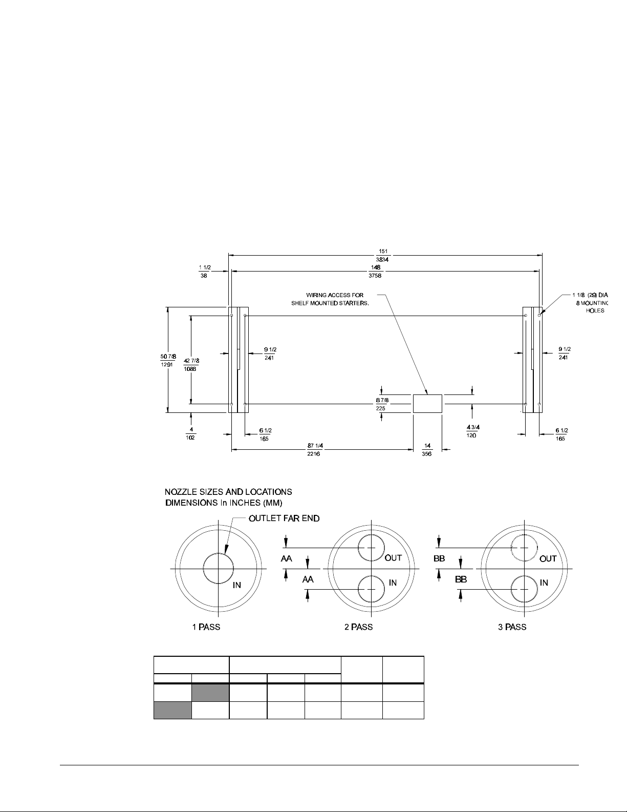
Figure 24 , Short shell dimensions R-22 Refrigerant (continued)
Vessel Code Head Connection U.S. Pipe
Size
Evap. Cond. 1P 2P 3P
E1810 8 6 5 4 7/8
C1810 8 6 5 4 7/8
AA BB
(124)
(124)
4 7/8
(124)
4 7/8
(124)
IM 692-1 PFS 155C - 315C 31
Page 32
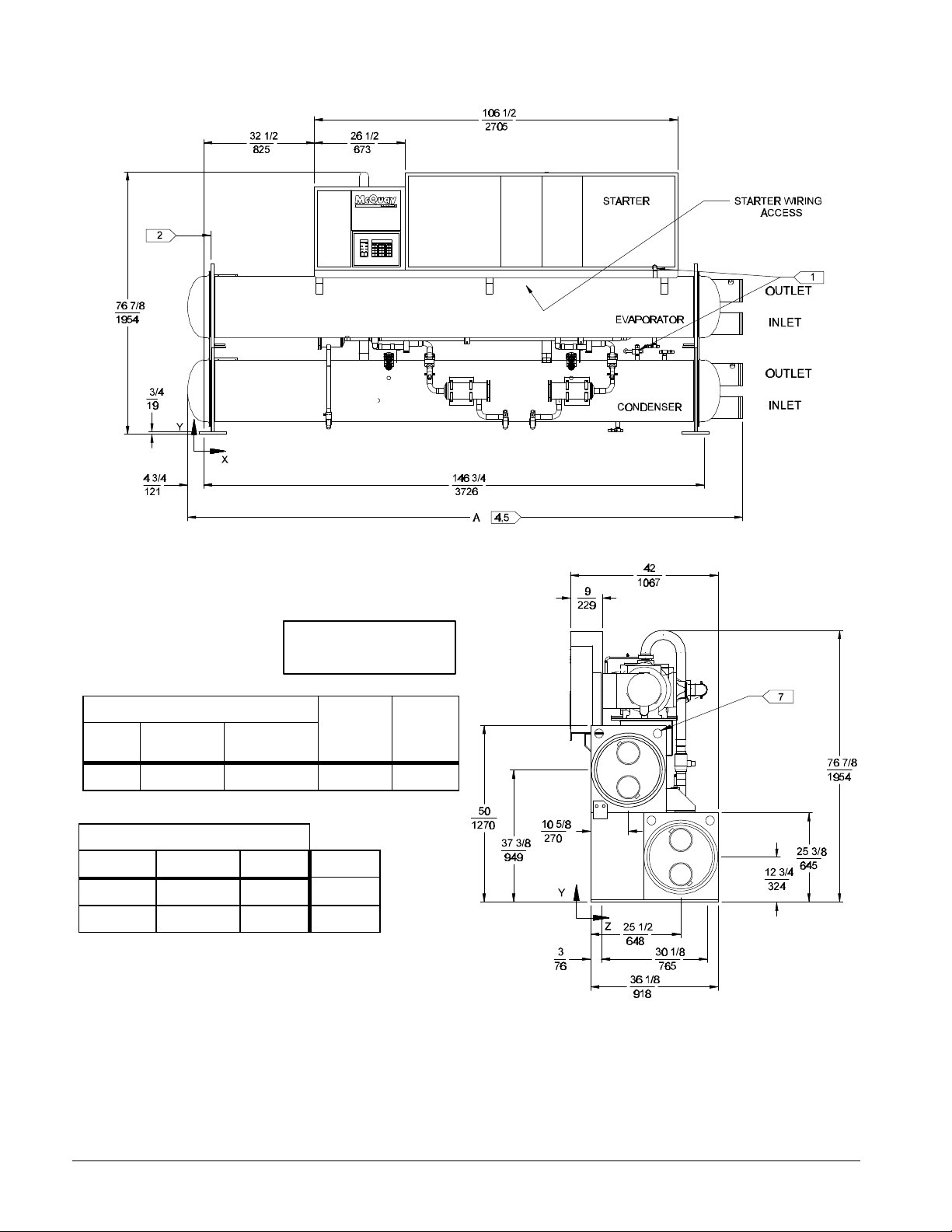
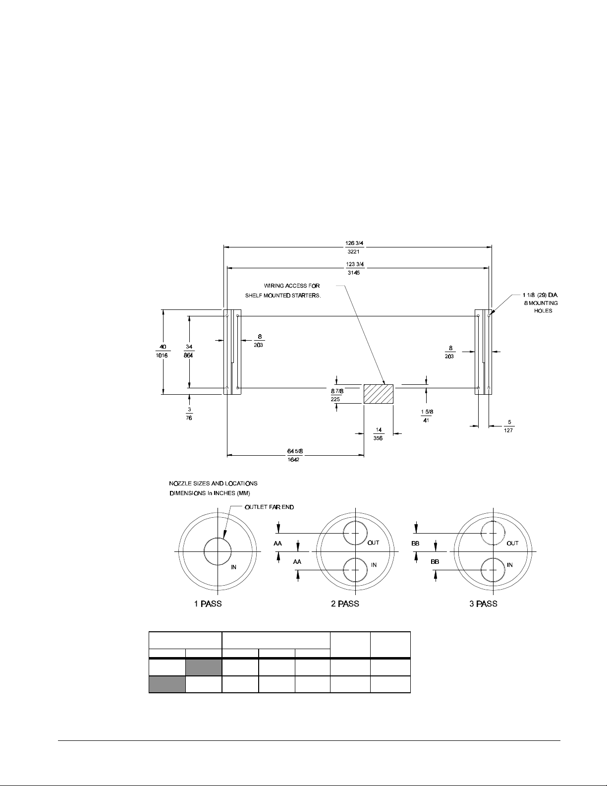
Figure 25, Standard shell dimemsions R-22 Refrigerant
All dimensions are shown
in inches and (mm)
Overall Length
1 & 3 2 & 4 Pass 2 & 4 Pass Height With
Pass Head Conn
on same end
169 1/4 162 3/4 169 1/4 76 7/8 42
(4299) (4134) (4299) (1953) (1067)
X Y Z see note
79 3/8 35 1/2 13 7/8 Oper.
(2016) (902) (353)
79 5/8 34 5/8 14 Ship
(2023) (880) (356)
A Overall
Head Conn.
both ends
Center of Gravity
with Starter
(Note 13) Starter
12
Overall
Width
See Notes on Next Page.
32 PFS 155C - 315C IM 692-1
Page 33

Notes for Figure 25
1. One half inch (13) FPT evaporator and condenser relief valves must be piped per ANSI/ASHRAE 15. (1 for each evaporator, 2
for each condenser).
2. 168 inches (4267) is required at either end of the tubesheet for tube replacement. 36 inches (914) is recommended on all
other sides and top for service clearance.
3. Final connections must allow for manufacturing tolerance.
4. Standard heads are shown. For dimensions of high pressure construction, water boxes, or flange type connections, contact
your representative.
5. For dimensions of different condenser or evaporator pass see table.
6. Unit is shipped with an operating charge of refrigerant and oil.
7. Six 2 1/2 inch (64) dia. Lifting holes are provided.
8. All water connections are given in standard U.S. Pipe sizes. Standard connections are suitable for welding or victualic
couplings.
9. Vibration isolator pads are provided for field installation 0.25 inches (6) thick when loaded.
10. f main power wiring is brought up through the floor, this wiring must be outside the envelope of the unit.
11. Pumpdown capacity is determined in accordance with ANSI/ASHRAE 15 for the maximum tube count.
12. These values are for units with standard wall thickness copper tubing only.
13. The shipping skid adds 4 inches (102) to the overall unit height.
Figure 25, Standard shell dimensions R-22 Refrigerant (continued)
Vessel Code Head Connection U.S. Pipe
Size
Evap. Cond. 1P 2P 3P
E1812 8 6 5 4 7/8
C1812 8 6 5 4 7/8
AA BB
(124)
(124)
4 7/8
(124)
4 7/8
(124)
IM 692-1 PFS 155C - 315C 33
Page 34
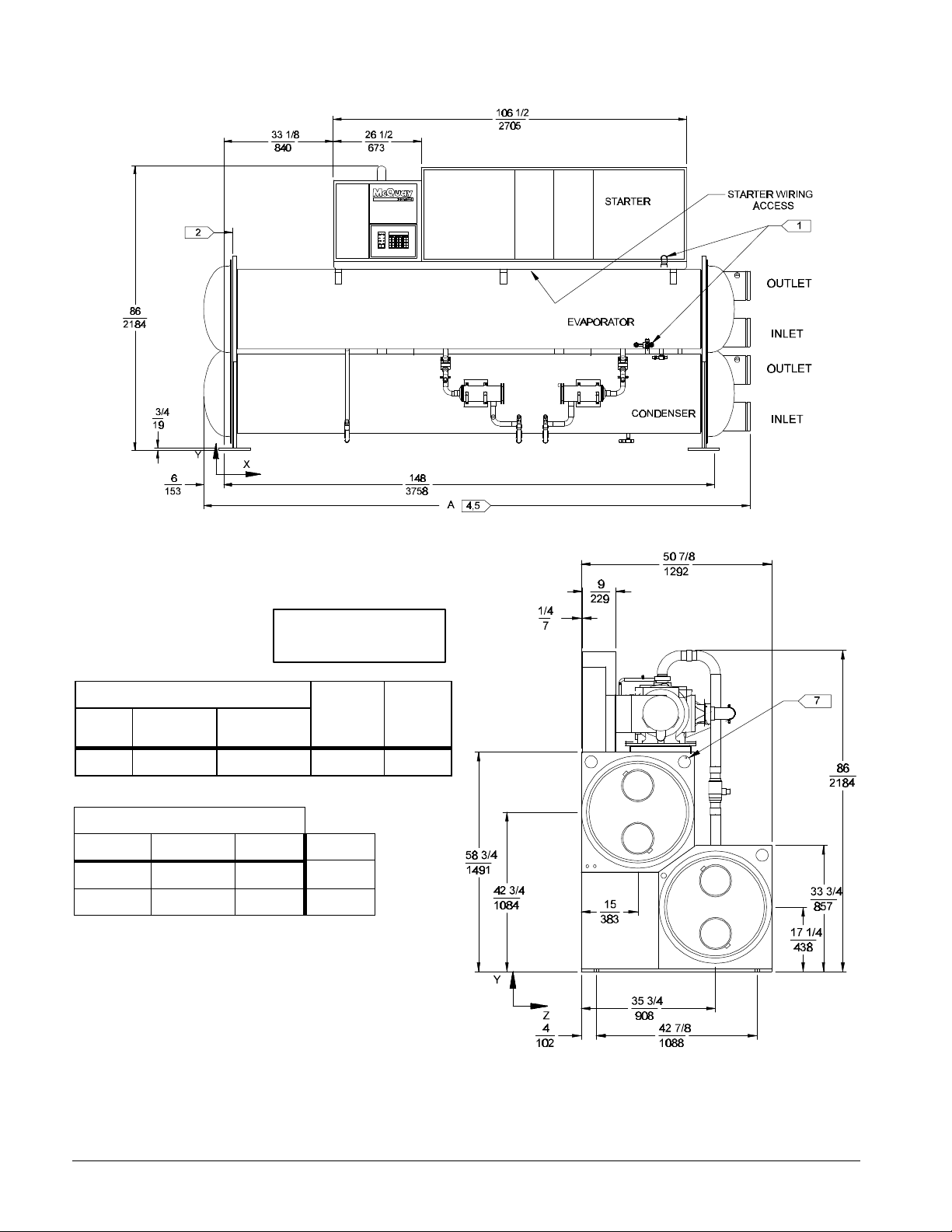
Figure 26, Long shell dimemsions R-22 Refrigerant Models 155-190
All dimensions are shown
in inches and (mm)
Overall Length
1 & 3 2 & 4 Pass 2 & 4 Pass Height With
Pass Head Conn
169 1/4 164 5/8 169 1/4 86 50 7/8
(4299) (4181) (4299) (2184) (1292)
X Y Z see note
77 3/4 38 1/4 20 3/8 Oper.
(2473) (899) (362)
78 1/4 37 7/8 20 3/8 Ship
(1988) (962) (518)
A Overall
on same end
Center of Gravity
with Starter
Head Conn.
both ends
(Note 13) Starter
12
Overall
Width
See Notes on Next Page.
34 PFS 155C - 315C IM 692-1
Page 35
Notes for Figure 26
1. One half inch (13) FPT evaporator and condenser relief valves must be piped per ANSI/ASHRAE 15. (1 for each evaporator, 2
for each condenser).
2. 168 inches (4267) is required at either end of the tubesheet for tube replacement. 36 inches (914) is recommended on all
other sides and top for service clearance.
3. Final connections must allow for manufacturing tolerance.
4. Standard heads are shown. For dimensions of high pressure construction, water boxes, or flange type connections, contact
your representative.
5. For dimensions of different condenser or evaporator pass see table
6. Unit is shipped with an operating charge of refrigerant and oil.
7. Six 2 1/2 inch (64) dia. Lifting holes are provided.
8. All water connections are given in standard U.S. Pipe sizes. Standard connections are suitable for welding or victualic
couplings.
9. Vibration isolator pads are provided for field installation 0.25 inches (6) thick when loaded.
10. f main power wiring is brought up through the floor, this wiring must be outside the envelope of the unit.
11. Pumpdown capacity is determined in accordance with ANSI/ASHRAE 15 for the maximum tube count.
12. These values are for units with standard wall thickness copper tubing only.
13. The shipping skid adds 4 inches (102) to the overall unit height.
Figure 26, Long shell dimensions R-22 Refrigerant Models 155-190(continued)
Vessel Code Head Connection U.S. Pipe
Size
Evap. Cond. 1P 2P 3P
E2412 10 8 8 7 1/8
C2412 10 8 8 7 1/8
AA BB
(181)
(181)
7 1/8
(181)
7 1/8
(181)
IM 692-1 PFS 155C - 315C 35
Page 36
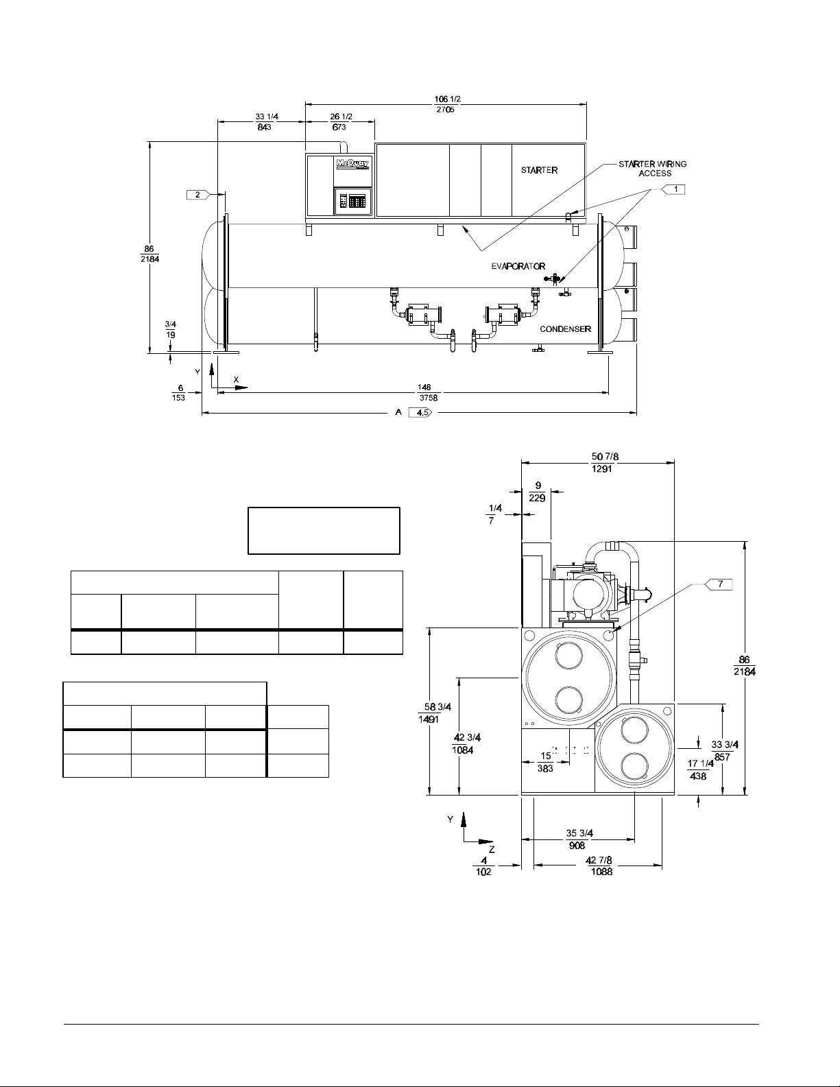
Figure 27, Long shell dimemsions R-22 Refrigerant Models 200-210
All dimensions are shown
in inches and (mm)
Overall Length
1 & 3 2 & 4 Pass 2 & 4 Pass Height With
Pass Head Conn
169 1/4 164 5/8 169 1/4 86 50 7/8
(4299) (4181) (4299) (2184) (1292)
Center of Gravity
X Y Z see note
78 1/8 39 1/2 20 3/4 Oper.
(1984) (1003) (527)
78 1/2 38 7/8 20 3/4 Ship
(1994) (987) (527)
A Overall
on same end
with Starter
Head Conn.
both ends
(Note 13) Starter
12
Overall
Width
See Notes on Next Page.
36 PFS 155C - 315C IM 692-1
Page 37
Notes for Figure 27
1. One Half inch (13) FPT evaporator and condenser relief valves must be piped per ANSI/ASHRAE 15. (1 for each evaporator, 2
for each condenser).
2. 168 inches (4267) is required at either end of the tubesheet for tube replacement. 36 inches (914) is recommended on all
other sides and top for service clearance.
3. Final connections must allow for manufacturing tolerance.
4. Standard heads are shown. For dimensions of high pressure construction, water boxes, or flange type connections, contact
your representative.
5. For dimensions of different condenser or evaporator pass see table
6. Unit is shipped with an operating charge of refrigerant and oil.
7. Six 2 1/2 inch (64) dia. Lifting holes are provided.
8. All water connections are given in standard U.S. Pipe sizes. Standard connections are suitable for welding or victualic
couplings.
9. Vibration isolator pads are provided for field installation 0.25 inches (6) thick when loaded.
10. If main power wiring is brought up through the floor, this wiring must be outside the envelope of the unit.
11. Pumpdown capacity is determined in accordance with ANSI/ASHRAE 15 for the maximum tube count.
12. These values are for units with standard wall thickness copper tubing only.
13. The shipping skid adds 4 inches (102) to the overall unit height.
Figure 27, Long shell dimensions R-22 Refrigerant Models 200-210(continued)
Vessel Code Head Connection U.S. Pipe
Size
Evap. Cond. 1P 2P 3P
E2412 10 8 8 7 1/8
C2212 10 8 6 5 3/4
AA BB
(181)
(146)
7 1/8
(181)
6 3/8
(162)
IM 692-1 PFS 155C - 315C 37
Page 38

Figure 28, Short shell dimemsions R-410A Refrigerant
All dimensions are shown
in inches and (mm)
Overall Length
1 & 3 2 & 4 Pass 2 & 4 Pass Height With
Pass Head Conn
146 1/4 140 3/4 146 3/4 84 3/4 43 7/8
(3715) (3577) (3715) (2141) (1114)
Center of Gravity
X Y Z see note
64 5/8 40 15 1/4 Oper.
(1642) 1016) (387)
64 5/8 39 15 3/8 Ship
(1642) (991) (391)
A Overall
on same end
with Starter
Head Conn.
both ends
(Note 13) Starter
12
Overall
Width
See Notes on Next Page.
38 PFS 155C - 315C IM 692-1
Page 39
Notes for Figure 28
1. one half inch (13) FPT evaporator and condenser relief valves must be piped per ANSI/ASHRAE 15. (1 for each evaporator, 2
for each condenser).
2. 144 inches (3658) is required at either end of the tubesheet for tube replacement. 36 inches (914) is recommended on all
other sides and top for service clearance.
3. Final connections must allow for manufacturing tolerance.
4. Standard heads are shown. For dimensions of high pressure construction, water boxes, or flange type connections, contact
your representative.
5. For dimensions of different condenser or evaporator pass see table
6. Unit is shipped with an operating charge of refrigerant and oil.
7. Six 2 1/2 inch (64) dia. Lifting holes are provided.
8. All water connections are given in standard U.S. Pipe sizes. Standard connections are suitable for welding or victualic
couplings.
9. Vibration isolator pads are provided for field installation 0.25 inches (6) thick when loaded.
10. f main power wiring is brought up through the floor, this wiring must be outside the envelope of the unit.
11. Pumpdown capacity is determined in accordance with ANSI/ASHRAE 15 for the maximum tube count.
12. These values are for units with standard wall thickness copper tubing only.
13. The shipping skid adds 4 inches (102) to the overall unit height.
Figure 28, Short shell dimensions R-410A Refrigerant (continued)
Vessel Code Head Connection U.S. Pipe
Size
Evap. Cond. 1P 2P 3P
E2212 10 8 6 5 3/4
C2012 10 8 5 5 5/8
AA BB
(145)
(143)
6 3/8
(161)
6 3/16
(157)
IM 692-1 PFS 155C - 315C 39
Page 40
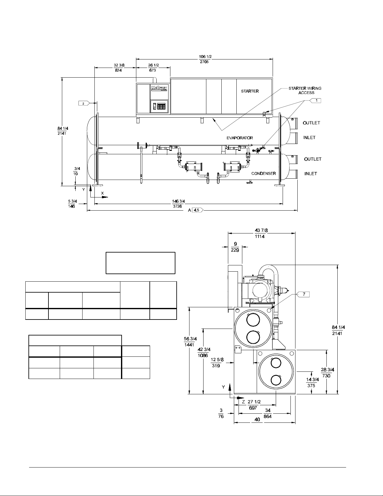
Figure 29, Standard shell dimemsions R-410A Refrigerant
All dimensions are shown
in inches and (mm)
Overall Length
1 & 3 2 & 4 Pass 2 & 4 Pass Height With
Pass Head Conn
on same end
169 1/4 163 3/4 169 1/4 84 1/4 47 7/8
(4299) (4159) (4299) (2141) (1114)
X Y Z see note
78 3/8 38 1/2 15 1/2 Oper.
(1991) (978) (394)
78 5/8 37 7/8 15 5/8 Ship
(1997) (962) (397)
A Overall
Head Conn.
both ends
Center of Gravity
with Starter
(Note 13) Starter
12
Overall
Width
See Notes on Next Page.
40 PFS 155C - 315C IM 692-1
Page 41
Notes for Figure 29
1. one half inch (13) FPT evaporator and condenser relief valves must be piped per ANSI/ASHRAE 15. (1 for each evaporator, 2
for each condenser).
2. 168 inches (4267) is required at either end of the tubesheet for tube replacement. 36 inches (914) is recommended on all
other sides and top for service clearance.
3. Final connections must allow for manufacturing tolerance.
4. Standard heads are shown. For dimensions of high pressure construction, water boxes, or flange type connections, contact
your representative.
5. For dimensions of different condenser or evaporator pass see table
6. Unit is shipped with an operating charge of refrigerant and oil.
7. Six 2 1/2 inch (64) dia. Lifting holes are provided.
8. All water connections are given in standard U.S. Pipe sizes. Standard connections are suitable for welding or victualic
couplings.
9. Vibration isolator pads are provided for field installation 0.25 inches (6) thick when loaded.
10. f main power wiring is brought up through the floor, this wiring must be outside the envelope of the unit.
11. Pumpdown capacity is determined in accordance with ANSI/ASHRAE 15 for the maximum tube count.
12. These values are for units with standard wall thickness copper tubing only.
13. The shipping skid adds 4 inches (102) to the overall unit height.
Figure 29, Standard shell dimensions R-410A Refrigerant (continued)
Vessel Code Head Connection U.S. Pipe
Size
Evap. Cond. 1P 2P 3P
E2212 10 8 6 5 3/4
C2012 8 6 5 5 5/8
AA BB
(145)
(143)
6 3/8
(161)
6 3/16
(157)
IM 692-1 PFS 155C - 315C 41
Page 42

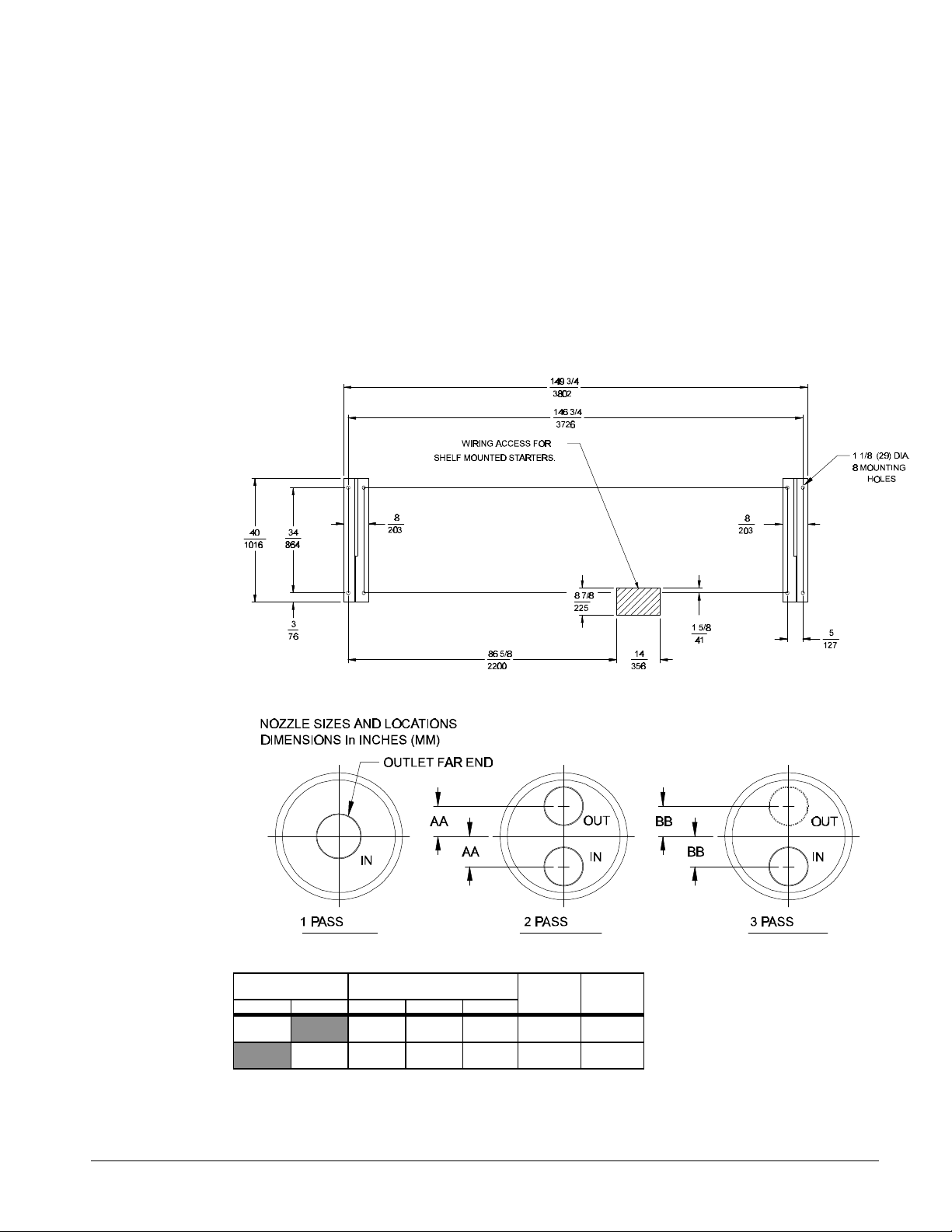
Figure 30, Long shell dimemsions R-410A Refrigerant
All dimensions are shown
in inches and (mm)
Overall Length
1 & 3 2 & 4 Pass 2 & 4 Pass Height With
Pass Head Conn
194 1/4 188 3/4 194 1/4 84 1/4 43 7/8
(4934) (4794) (4934) (2141) (1114)
X Y Z see note
90 1/8 36 3/8 16 1/4 Oper.
(2289) (924) (413)
90 1/2 35 3/4 16 1/4 Ship
(2299) (908) (413)
A Overall
on same end
Center of Gravity
with Starter
Head Conn.
both ends
(Note 13) Starter
12
Overall
Width
See Notes on Next Page.
42 PFS 155C - 315C IM 692-1
Page 43

Notes for Figure 30
1. one half inch (13) FPT evaporator and condenser relief valves must be piped per ANSI/ASHRAE 15. (1 for each evaporator, 2
for each condenser).
2. 192 inches (4877) is required at either end of the tubesheet for tube replacement. 36 inches (914) is recommended on all
other sides and top for service clearance.
3. Final connections must allow for manufacturing tolerance.
4. Standard heads are shown. For dimensions of high pressure construction, water boxes, or flange type connections, contact
your representative.
5. For dimensions of different condenser or evaporator pass see table
6. Unit is shipped with an operating charge of refrigerant and oil.
7. Six 2 1/2 inch (64) dia. Lifting holes are provided.
8. All water connections are given in standard U.S. Pipe sizes. Standard connections are suitable for welding or victualic
couplings.
9. Vibration isolator pads are provided for field installation 0.25 inches (6) thick when loaded.
10. f main power wiring is brought up through the floor, this wiring must be outside the envelope of the unit.
11. Pumpdown capacity is determined in accordance with ANSI/ASHRAE 15 for the maximum tube count.
12. These values are for units with standard wall thickness copper tubing only.
13. The shipping skid adds 4 inches (102) to the overall unit height.
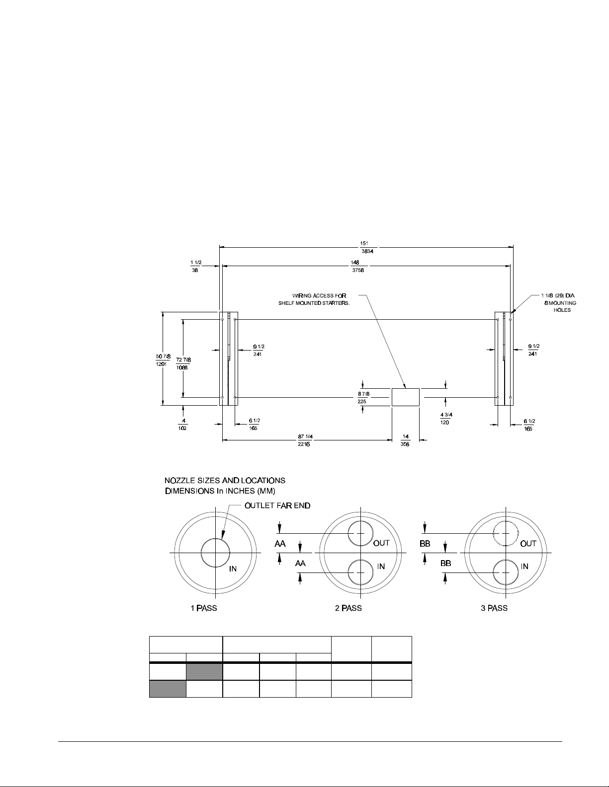
Figure 30, Long shell dimensions R-410A Refrigerant (continued)
Vessel Code Head Connection U.S. Pipe
Size
Evap. Cond. 1P 2P 3P
E2214 10 8 6 5 3/4
C2214 10 8 6 5 3/4
AA BB
(145)
(146)
6 3/8
(161)
6 3/8
(162)
IM 692-1 PFS 155C - 315C 43
Page 44

Field Wiring
CAUTION
PFS unit compressors are single direction rotation compressors. For this reason proper
phasing of electrical power is essential. Electrical phasing must be A, B, C clockwise for
electrical phases 1, 2 and 3 (A=L1 ,B=L2,C=L3). The unit is supplied with single point
factory power connection and includes one MotorSaver phase failure, phase reversal
protective device that will prevent operation of the unit with incorrect power phasing. The
MotorSaver is factory wired and tested. Do not alter the wiring to the MotorSaver.
General Information
Wiring must comply with all applicable codes and ordinances. Warranty is void if wiring is not in
accordance with specifications.
Copper wire must be used for all wiring.
The PFS is typically supplied with the main power wiring for single point power connection. A
single large power terminal block is provided for field connections. Wiring within the unit is sized
according to the National Electrical Code. A single field-mounted disconnect (supplied by others) is
required. An optional factory mounted transformer for the 115 volt control circuit may have been
provided.
Main power must enter the control panel at the location indicated on the unit illustration.
Table 9, Compressor amp draw
PFS Rated Load Amps Locked Rotor Amps
Unit Volts Hz Compressor Compressor
Size Delta-Delta Start
208 179 179 934 934
230 162 162 1042 1042
155C 380 60 98 98 604 604
460 81 81 489 489
575 65 65 377 377
208 179 223 934 934
230 162 202 1042 1042
170C 380 60 98 122 604 604
460 81 101 489 489
575 65 81 377 377
208 179 254 934 934
230 162 230 1042 1042
180C 380 60 98 139 604 604
460 81 115 489 489
575 65 92 377 377
208 223 223 934 934
230 202 202 1042 1042
190C 380 60 122 122 604 604
460 101 101 489 489
575 81 81 377 377
208 223 254 934 934
230 202 230 1042 1042
200B 380 60 122 139 604 604
460 101 115 489 489
575 81 92 377 377
208 254 254 934 934
230 230 230 1042 1042
210C 380 60 139 139 604 604
460 115 115 489 489
575 92 92 377 377
NOTES:
1. Allowable voltage is within ±10 % of nameplate rating.
Comp. 1 Comp. 2 Comp. 1 Comp. 2
44 PFS 155C - 315C IM 692-1
Page 45

2. Compressor RLA values are for wiring sizing only. They do not reflect normal operating current draw at unit rated capacity.
Table 10, Compressor Amp Draw
PFS Rated Load Amps Locked Rotor Amps
Unit Volts Hz Compressor Compressor
Size Delta-Delta Start
Comp. 1 Comp. 2 Comp. 1 Comp. 2
208 286 286 934 934
230 259 259 1042 1042
235C 380 60 157 157 604 604
460 130 130 489 489
575 104 104 377 377
208 286 357 934 934
230 259 323 1042 1042
255C 380 60 157 195 604 604
460 130 162 489 489
575 104 130 377 377
208 286 406 934 934
230 259 368 1042 1042
270C 380 60 157 222 604 604
460 130 184 489 489
575 104 147 377 377
208 357 357 934 934
230 323 323 1042 1042
280C 380 60 195 195 604 604
460 162 162 489 489
575 130 130 377 377
208 357 406 934 934
230 323 368 1042 1042
300C 380 60 195 222 604 604
460 162 184 489 489
575 130 147 377 377
208 406 406 934 934
230 368 368 1042 1042
315C 380 60 222 222 604 604
460 184 184 489 489
NOTES:
1. Allowable voltage limit is within ±10 percent of nameplate rating.
2. Compressor RLA values are for wire sizing only. They do not reflect normal operating current draw at unit rated capacity.
575 147 147 377 377
IM 692-1 PFS 155C - 315C 45
Page 46

Table 11, Customer wiring information
PFS Wiring to unit Power Block Wiring to Disconnect Switch
Unit Volts Hz Power Block Optional Disconnect Switch
Size Terminal Size Connector Wire Range (per phase) Size Connector Wire Range
Amps (Copper Wire Only) (Copper Wire Only)
208 665 (1) #6-350 MCM & (1) #4-500 MCM 600 (2) 250-350 MCM
230 665 (1) #6-350 MCM & (1) #4-500 MCM 400 (2) 3/0-250 MCM
155C 380 60 335 (1) #6-400 MCM 250 (1) #4-350 MCM
460 335 (1) #6-400 MCM 250 (1) #4-350 MCM
575 335 (1) #6-400 MCM 250 (1) #4-350 MCM
208 665 (1) #6-350 MCM & (1) #4-500 MCM 600 (2) 250-350 MCM
230 665 (1) #6-350 MCM & (1) #4-500 MCM 600 (2) 250-350 MCM
170C 380 60 335 (1) #6-400 MCM 400 (2) 3/0-250 MCM
460 335 (1) #6-400 MCM 250 (1) #4-350 MCM
575 335 (1) #6-400 MCM 250 (1) #4-350 MCM
208 665 (1) #6-350 MCM & (1) #4-500 MCM 600 (2) 250-350 MCM
230 665 (1) #6-350 MCM & (1) #4-500 MCM 600 (2) 250-350 MCM
180C 380 60 335 (1) #6-400 MCM 400 (1) 2/0-500 MCM
460 335 (1) #6-400 MCM 250 (1) #4-350 MCM
575 335 (1) #6-400 MCM 250 (1) #4-350 MCM
208 665 (1) #6-350 MCM & (1) #4-500 MCM 600 (2) 250-350 MCM
230 665 (1) #6-350 MCM & (1) #4-500 MCM 600 (2) 250-350 MCM
190C 380 60 335 (1) #6-400 MCM 400 (1) 2/0-500 MCM
460 335 (1) #6-400 MCM 250 (1) #4-350 MCM
575 335 (1) #6-400 MCM 250 (1) #4-350 MCM
208 665 (1) #6-350 MCM & (1) #4-500 MCM 600 (2) 250-350 MCM
230 665 (1) #6-350 MCM & (1) #4-500 MCM 600 (2) 250-350 MCM
200C 380 60 335 (1) #6-400 MCM 400 (1) 2/0-500 MCM
460 335 (1) #6-400 MCM 250 (1) #4-350 MCM
575 335 (1) #6-400 MCM 250 (1) #4-350 MCM
208 665 (1) #6-350 MCM & (1) #4-500 MCM 600 (2) 250-350 MCM
230 665 (1) #6-350 MCM & (1) #4-500 MCM 600 (2) 250-350 MCM
210C 380 60 335 (1) #6-400 MCM 400 (1) 2/0-500 MCM
460 335 (1) #6-400 MCM 400 (1) 2/0-500 MCM
575 335 (1) #6-400 MCM 250 (1) #4-350 MCM
Note:
Allowable voltage is within ±10 percent of nameplate rating.
(per phase)
46 PFS 155C - 315C IM 692-1
Page 47

Table 12, Customer Wiring Information
PFS Wiring to unit Power Block Wiring to Main Circuit Breaker
Unit Volts Hz Power Block Optional Main Circuit Breaker
Size Terminal Size Connector Wire Range (per phase) Size Connector Wire Range (per phase)
208 665 / 665 (1) # 6-350 MCM & (1) # 4-500 MCM & NA NA
230 665 / 665 (1) # 6-350 MCM & (1) # 4-500 MCM & NA NA
235C 60 (1) # 6-350 MCM & (1) # 4-500 MCM
380 665 (1) # 6-350 MCM & (1) # 4-500 MCM 400 (2) 3/0-250 MCM
460 335 (1) # 6-400 MCM 400 (1) 2/0-500 MCM
575 335 (1) # 6-400 MCM 250 (1) #4-350 MCM
208 665 / 665 (1) # 6-350 MCM & (1) # 4-500 MCM & NA NA
230 665 / 665 (1) # 6-350 MCM & (1) # 4-500 MCM & NA NA
255C 60 (1) # 6-350 MCM & (1) # 4-500 MCM
380 665 (1) # 6-350 MCM & (1) # 4-500 MCM 600 (2) 250-350 MCM
460 665 (1) # 6-350 MCM & (1) # 4-500 MCM 400 (1) 2/0-500 MCM
575 335 (1) # 6-400 MCM 400 (1) 2/0-500 MCM
208 665 / 665 (1) # 6-350 MCM & (1) # 4-500 MCM & NA NA
230 665 / 665 (1) # 6-350 MCM & (1) # 4-500 MCM & NA NA
270C 60 (1) # 6-350 MCM & (1) # 4-500 MCM
380 665 (1) # 6-350 MCM & (1) # 4-500 MCM 600 (2) 250-350 MCM
460 665 (1) # 6-350 MCM & (1) # 4-500 MCM 400 (1) 2/0-500 MCM
575 665 (1) # 6-350 MCM & (1) # 4-500 MCM 400 (1) 2/0-500 MCM
208 665 / 665 (1) # 6-350 MCM & (1) # 4-500 MCM & NA NA
230 665 / 665 (1) # 6-350 MCM & (1) # 4-500 MCM & NA NA
280C 60 (1) # 6-350 MCM & (1) # 4-500 MCM
380 665 (1) # 6-350 MCM & (1) # 4-500 MCM 600 (2) 250-350 MCM
460 665 (1) # 6-350 MCM & (1) # 4-500 MCM 400 (1) 2/0-500 MCM
575 335 (1) # 6-400 MCM 400 (1) 2/0-500 MCM
208 665 / 665 (1) # 6-350 MCM & (1) # 4-500 MCM & NA NA
230 665 / 665 (1) # 6-350 MCM & (1) # 4-500 MCM & NA NA
300C 60 (1) # 6-350 MCM & (1) # 4-500 MCM
380 665 (1) # 6-350 MCM & (1) # 4-500 MCM 600 (2) 250-350 MCM
460 665 (1) # 6-350 MCM & (1) # 4-500 MCM 400 (2) 3/0-250 MCM
575 665 (1) # 6-350 MCM & (1) # 4-500 MCM 400 (1) 2/0-500 MCM
208 665 / 665 (1) # 6-350 MCM & (1) # 4-500 MCM & NA NA
230 665 / 665 (1) # 6-350 MCM & (1) # 4-500 MCM & NA NA
315C 60 (1) # 6-350 MCM & (1) # 4-500 MCM
380 665 (1) # 6-350 MCM & (1) # 4-500 MCM 600 (2) 250-350 MCM
460 665 (1) # 6-350 MCM & (1) # 4-500 MCM 600 (2) 250-350 MCM
575 665 (1) # 6-350 MCM & (1) # 4-500 MCM 400 (1) 2/0-500 MCM
NOTE:
Allowable voltage is within ±10 percent of nameplate rating
Amps (Copper Wire Only) (Copper Wire Only)
Ckt.1 / Ckt.2 Ckt.1 / Ckt.2 Ckt.1 / Ckt.2 Ckt.1 / Ckt.2
(1) # 6-350 MCM & (1) # 4-500 MCM
(1) # 6-350 MCM & (1) # 4-500 MCM
(1) # 6-350 MCM & (1) # 4-500 MCM
(1) # 6-350 MCM & (1) # 4-500 MCM
(1) # 6-350 MCM & (1) # 4-500 MCM
(1) # 6-350 MCM & (1) # 4-500 MCM
IM 692-1 PFS 155C - 315C 47
Page 48
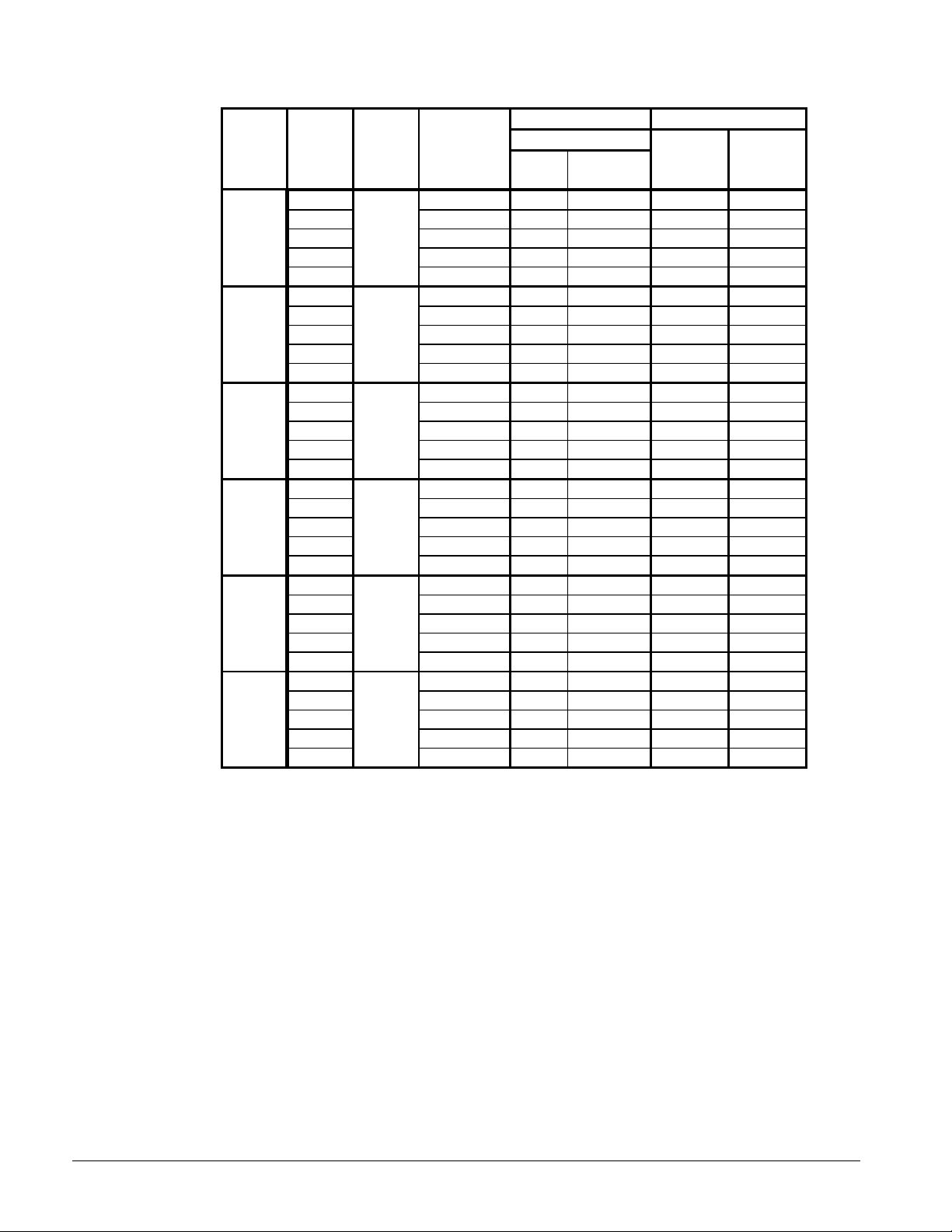
Table 13, Electrical data
PFS Minimum Power Supply Field Fuse Size
Unit Volts Hz Circuit Field Wire
Size Ampacity Qty. Wire Recom- Maximum
(MCA) (3) Gauge mended
208 403 6 250 450 500
230 365 6 3/0 450 500
155C 380 60 221 3 4/0 250 300
460 183 3 3/0 225 250
575 147 3 1/0 175 200
208 458 6 250 600 600
230 415 6 250 500 600
170C 380 60 251 3 250 300 350
460 208 3 4/0 250 300
575 167 3 2/0 200 225
208 497 6 250 600 700
230 450 6 250 600 600
180C 380 60 272 3 300 350 400
460 225 3 4/0 300 300
575 180 3 3/0 250 250
208 502 6 250 600 700
230 455 6 250 600 600
190C 380 60 275 3 300 350 350
460 228 3 4/0 300 300
575 183 3 3/0 225 250
208 541 6 300 700 700
230 490 6 250 600 700
200C 380 60 296 3 350 350 400
460 245 3 250 300 350
575 196 3 3/0 225 250
208 572 6 350 700 800
230 518 6 300 600 700
210C 380 60 313 3 400 400 450
460 259 3 300 300 350
575 207 3 4/0 250 250
NOTES:
1. Allowable voltage range is within ±10% of nameplate rating.
2. Minimum circuit ampacity is equal to 125% of the RLA of the largest motor plus 100% of the RLA of all other loads in the
circuit.
3. Recommended power lead wire sizes based on three conductors per conduit at 100% conductor ampacity using 75°C wire
and no more than 3 conductors per conduit.
4. For six conductors per conduit current carrying capacity is reduced by 20%. Consult the National Electical Code for wire
sizing. All terminal block connections must be made with copper wire (type THW or THHN).
5. Recommended time delay fuse size or circuit breakers (Canadian units only) is equal to 150% of the largest compressormotor RLA plus 100% of all other loads on the circuit. Maximum time delay fuse size or circuit breakers (Canadian units only)
is equal to 225% of the largest compressor-motor RLA plus 100% of all other loads on the circuit.
48 PFS 155C - 315C IM 692-1
Page 49
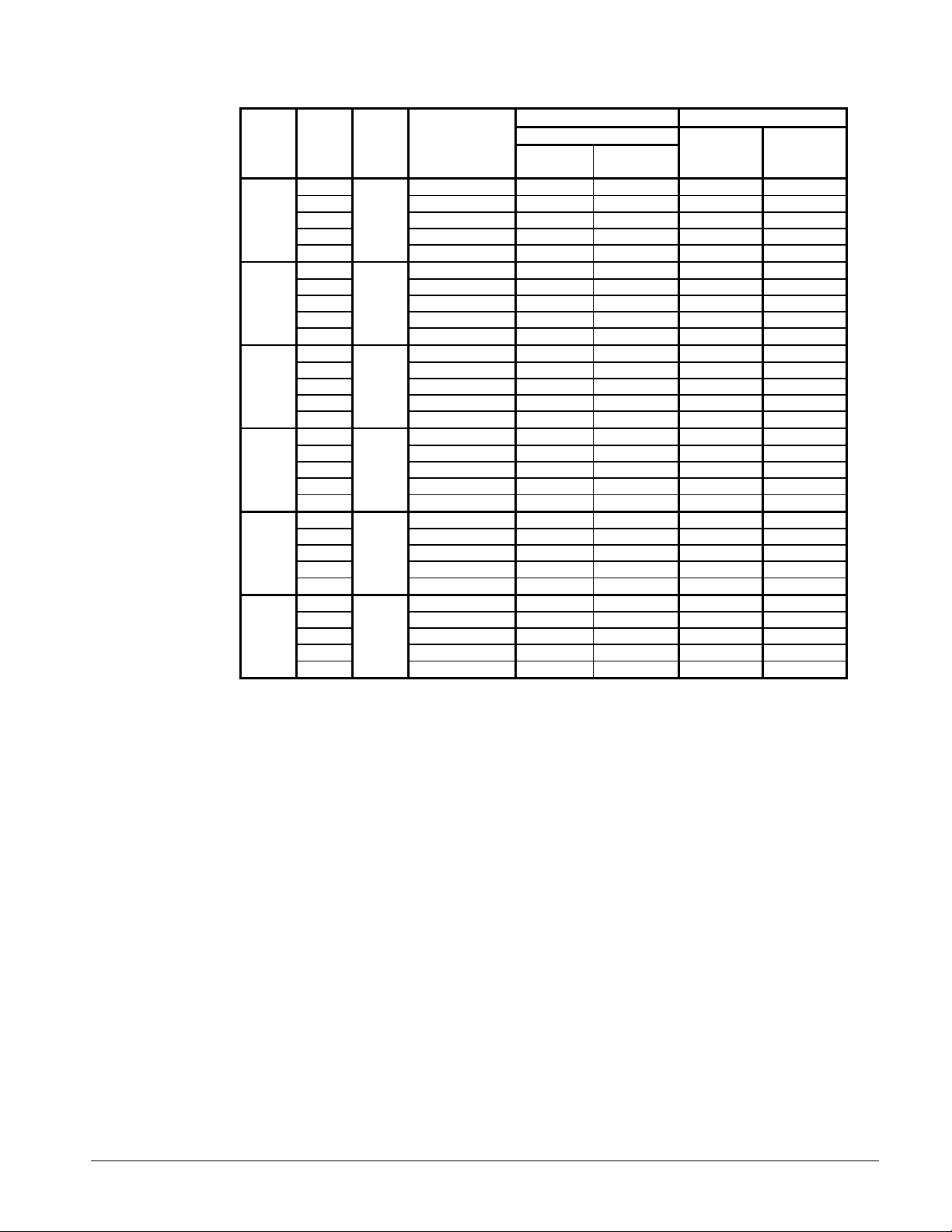
Table 14, Electrical Data
PFS Minimum Power Supply Field Fuse Size
Unit Volts Hz Circuit Ampacity Field Wire Recom- Maximum
Size (MCA) Qty.(3) Wire Guage mended
208 358 / 358 6 / 6 3/0 / 3/0 450 / 450 600 / 600
230 324 / 324 6 / 6 2/0 / 2/0 400 / 400 500 / 500
235C 380 60 353 6 3 / 0 400 500
460 293 3 350 350 400
575 234 3 250 300 300
208 358 / 446 6 / 6 3/0 / 4/0 450 / 600 600 / 800
230 324 / 404 6 / 6 2/0 / 4/0 400 / 500 500 / 700
255C 380 60 401 6 250 450 500
460 333 3 400 400 450
575 267 3 300 300 350
208 358 / 508 6 / 6 3/0 / 250 450 / 700 600 / 800
230 324 / 460 6 / 6 2/0 / 4/0 400 / 600 500 / 800
270C 380 60 435 6 250 500 500
460 360 3 500 450 500
575 288 3 350 350 400
208 446 / 446 6 / 6 4/0 / 4/0 600 / 600 800 / 800
230 404 / 404 6 / 6 4/0 / 4/0 500 / 500 700 / 700
280C 380 60 439 6 250 500 600
460 365 3 500 450 500
575 293 3 350 350 400
208 446 / 508 6 / 6 4/0 / 250 600 / 700 800 / 800
230 404 / 460 6 / 6 4/0 / 4/0 500 / 600 700 / 800
300C 380 60 473 6 250 600 600
460 392 6 3 / 0 450 500
575 314 3 400 400 450
208 508 / 508 6 / 6 250 / 250 700 / 700 800 / 800
230 460 / 460 6 / 6 4/0 / 4/0 600 / 600 800 / 800
315C 380 60 500 6 250 600 700
460 414 6 250 500 500
575 331 3 400 400 450
NOTES:
1. Allowable voltage limit is within ±10 percent of nameplate rating.
2. 235C-315C units for 208V & 230V applications require two electrical circuits and have two power blocks. Optional "main
circuit breaker" and "compressor circuit breakers" are not available with these units.
3. Recommended power lead wire sizes based on three conductors per conduit at 100% conductor ampacity using 75°C wire
and no more than 3 conductors per conduit.
4. For six conductors per conduit current carrying capacity is reduced by 20%. Consult the National Electical Code for wire
sizing. All terminal block connections must be made with copper wire (type THW or THHN).
5. Recommended time delay fuse size or circuit breakers (Canadian units only) is equal to 150% of the largest compressormotor RLA plus 100% of all other loads on the circuit. Maximum time delay fuse size or circuit breakers (Canadian units only)
is equal to 225% of the largest compressor-motor RLA plus 100% of all other loads on the circuit.
Ckt.1 / Ckt.2 Ckt.1 / Ckt.2 Ckt.1 / Ckt.2 Ckt.1 / Ckt.2 Ckt.1 / Ckt.2
IM 692-1 PFS 155C - 315C 49
Page 50
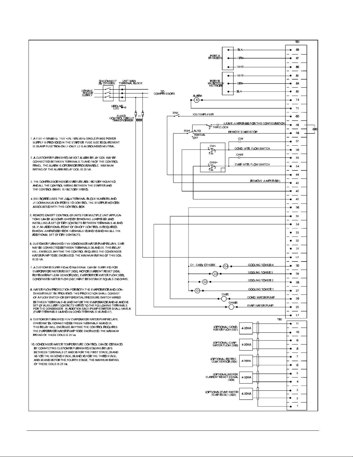
Figure 31, Typical Field Wiring
50 PFS 155C - 315C IM 692-1
Page 51

Pre-Start-up
1. Open all electrical disconnects and check electrical connections are tight.
2. Verify water piping flow directions are correct and properly connected at the evaporator and
3. Using a phase tester, verify electrical phasing is A-B-C clockwise (A=L1, B=L2,C=L3).
4. Verify unit power supply is within 10% of nameplate rating.
5. Verify power supply wiring is the correct size and has a minimum temperature insulation rating
6. Verify all mechanical and electrical inspections have been completed according to local code.
7. Make certain all auxilliary control equipment is operative and an adequate cooling load is
8. Check all compressor valve connections for tightness.
9. Open compressor suction valve until backseated. (This is an optional valve)
10. Open discharge shutoff valve until backseated
11. Vent air from the evaporator and condenser water system piping.
12. Open all water flow valves and start chilled water pump.
13. Check all piping for leaks.
14. Flush the evaporator and condenser system piping.
condenser.
of 75°C.
available.
Sequence of Operation
The following sequence of operation is typical for McQuay models PFS155C through PFS315C
screw water chillers. The sequence may vary depending on the software revision or various options
that maybe installed on the chiller.
Initial Conditions
Before energizing the control box, do the following:
1. Verify the two control circuits are powered through the primary fuses FU1, FU2 and the
secondary fuse FU3.
2. Verify power is developed through the transformer CPT in the starter and is 120 VAC on the
secondary.
3. Make certain the S1 switch is in the off position.
When applying power to the control for the first time do the following:
1. Open left door and the top door to each control box.
2. Apply power and observe the following:
§ Display lights up
§ Unit Status screen appears
§ EXV board lights rapidly sequence closed.
3. Listen for stepper motors closing with a racheting sound.
4. Verify Unit Status Screen on the display indicates Off: Front Panel Sw.
IM 692-1 PFS 155C - 315C 51
Page 52
Off Conditions
With the power on the controller there several off states:
Off: Manual: when the setpoint in menu “11 Control Mode” is set to the Mode= Manual Off. To
change, simply set the Mode= Auto: Network (or any other running mode).
Off: Front Panel Sw: when the panel switch is in the “Stop” position. To change move the switch
to “Auto” position.
Off Alarm remove the alarm state then clear the alarm to remove this off state.
Off Compressor 1 or Off Compressor 2 is the on / off switch inside the top right control box
door. Turn to ‘on’ to clear.
Alarm
The alarm light on the front panel illuminates when the particular control receives an active alarm
state. The unit or a particular compressor will be locked out. The other compressor will start if only
one is locked out by a compressor fault.
Initial Start-up
CAUTION
Initial Start-up must be performed by McQuayService personnel.
1. Set up control as described in Initial Conditions.
2. Turn front panel switch to Auto position. (chilled water flow pump relay will energize.)
3. If the field installed flow indicator does not indicated chilled water flow after 30 seconds, then
the alarm output will be energized.
Note: The unit starts the compressor with the least starts and run hours while in auto lead
lag setting
4. When the Active Setpoint is 3 °F lower than the actual leaving water temperature, the chiller
starts.
5. When the chiller starts the following occurs:
§ Crank case heaters de-energize
§ Compressor starts
§ Liquid injection solenoid is energized
§ Motor cooling solenoid is energized
§ Suction injection solenoids are energized
6. Suction injection will turn off when the following conditions have been met:
§ Discharge superheat drops below 3 °F
§ Liquid Presence sensor shows liquid
§ Absolute Pressure ratio is greater than 1.2 (Abs. Condenser Psia / Abs. Evaporator Psia)
52 PFS 155C - 315C IM 692-1
Page 53

7. The unit status changes:
FROM TO
EvapOn-Recirc **Sec All Systems Off
All Systems Off MCR Started
MCR Started Pre-purge
Pre-purge Open Solenoid
Open Solenoid Running Min Amp Lim
Running Min Amp Lim Running: % Cap 50
8. The following occurs if additional cooling capacity is required:
§ Controllers add capacity by changing the capacity control solenoids outputs 6, 7, and 8.
§ As capacity increases the second compressor is started
§ After both compressor are running the unit continues to load by changing the capacity
control solenoids outputs 12, 13, and 14.
Load Recycle
As chilled water requirements lessen, the controls unload the compressors until the chilled water
drops below the lag cutoff point for the delay time required. The control will shut off the lag
compressor and reduced load will cause the leaving water temperature to drop 3 ° F below the active
setpoint. The compressor de-energizes on Load Recycle and the display will show Waiting For
Load. The chilled water pump will remain on.
IM 692-1 PFS 155C - 315C 53
Page 54

13600 Industrial Park Boulevard, P.O. Box 1551, Minneapolis, MN 55440 USA (612) 553-5330
 Loading...