

Page 1
Page 2

Page 3

Introduction
I
Refer to Installation and Maintenance Bulletin 549 for additional information on the MicroTech controller.
General Description
McQuay
plete, self-contained automatic refrigerating unitsthat include
the latest in engineering components arranged to provide a
compact and efficient unit. Each unit is completely assembled,
factory wired, evacuated, charged, tested and comes complete and ready for installation. Each unit consists of twin
water cooled condensers with integral subcooler sections,
multiple accessible semi-hermetic single screw compressors, replaceabletubedual circuit shell-and-tubeevaporator,
and complete refrigerant piping. Liquid line components
included are manual liquid line shutoff valves, charging valves,
StarGateTM
water cooled water chillers are com-
Nomenclature
filter-driers, liquid line solenoid valves, sightglass/moisture
indicators, and electronic expansion valves. Other features
include compressor heaters, automatic one time pumpdown
of refrigerant circuit upon circuit shutdown, and an advanced
fully integrated microprocessor control system.
The electrical control center includes all safety and operating controls necessary for dependable automatic operation,
(the high and low pressure controls are external from the
electrical control center). Compressors are protected by
state overload protection and over temperature protection.
Field installed fused disconnect offers additional protection.
solid-
PFS-XXXA
TTT IT
Watercooled
Dual
Screw
compressor
When the equipment is received, all items should be carefully
checked against the bill of lading to insure a complete
shipment. All units should be carefully inspected for damage
upon arrival. All shipping damage must be reported to the
carrier and a claim must be filed with the carrier. The unit
serial plate should be checked before unloading the unit to
2
1
1
( (
Inspection
150=150
165=165
180=180
190=190
200=200
be sure that it agrees with the power supply available.
Physical damage to unit after acceptance is not the
sibility of McQuay International.
Note: Units shipping and operating weights are available
in the physical data table on page 15.
tons
tons
tons
tons
tons
respon-
IM 609 / Page 3
Page 4
Installation & Start-up
Note:
Start-up by McQuay Service is included on all units sold for
installation within North America excludinq Mexico. Two
weeks prior notification of start-up is required. The contractor should obtain a copy of the Start-up Scheduled Request
Form from the sales representative or from the nearest office
of McQuayService.
Installation and maintenance are to be performed only by qualified personnel who are familiar with local codes
and regulations, and experienced with this type of equipment.
Handling
Care should be taken to avoid rough handling or shock due
to impact or dropping the unit. Do not push or pull the unit
from anything other than the base.
Never allow any part of the unit to fall during unloading or
moving as this may result in serious damage.
Every PFS is shipped with a full refrigerant charge. For
shipping reasons, thechargewill be stored in the condensers
and is isolated by the manual condenser liquid valve and the
Moving the Unit
The PFS water chiller is shipped mounted on heavy wooden
skids to protect the unit from accidental damage and permit
easy handling, and moving.
It is recommended that all moving and handling be
performed with the skids under the unit when possible and
that the skids not be removed until the unit is in the final
location.
When moving the unit, dollies or simple rollers can be
used under the skids.
Never put the weight of the unit against the control box.
In moving, always apply pressure to the base on skids
only and not to the piping or shells. A long bar
the unit easily. Avoid dropping the unit at the end of the roll.
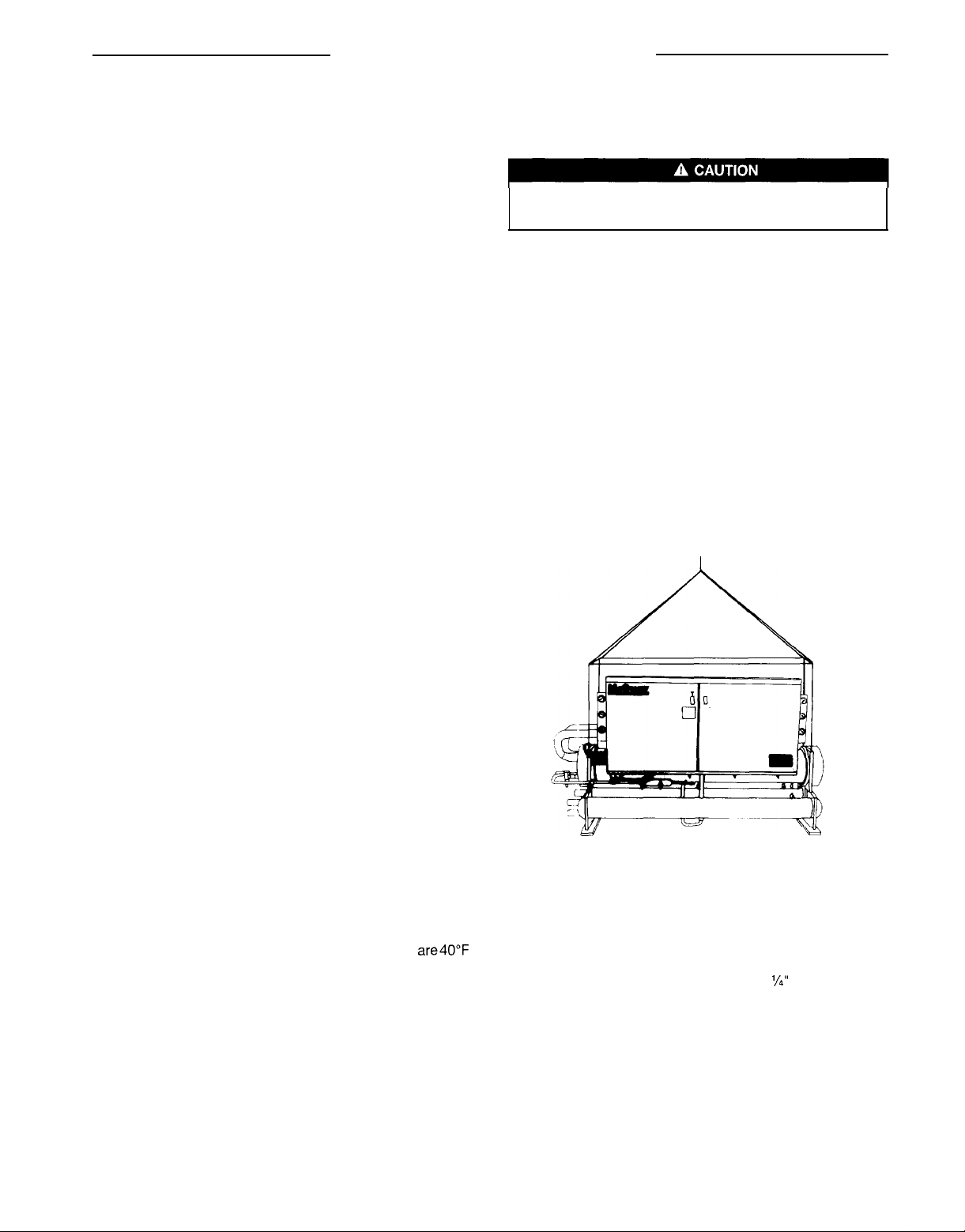
If the unit must be hoisted, it is necessary to lift the unit
by attaching cables or chains at the lifting holes in the
evaporator tube sheets. Speader bars must be used to
protect the control cabinet and other areas of the chiller (see
Figure 1).
Do not attach slings to piping or equipment. Move unit in
the upright horizontal position at all times. Set unit down
gently when lowering from the trucks or rollers.
will
help move
Sharp edges are a potential injury hazard. Avoid contact
with them.
discharge valve.
Should the unit be damaged, allowing the refrigerant to
escape, there may be danger of suffocation in the equipment
area since the refrigerant will displace the air. Be sure to
review Environmental ProtectionAgency(EPA) requirements
should unit damage occur. Avoid exposing an open flame to
refrigerant.
Figure 1. Suggested lifting arrangement
Location
Unit is designed for indoor application and must be located in the control box is supplied as standard fortemporary protecan area
(4°C) or above. A good rule of thumb is to place the unit where
ambients are at least 5°F (3°C) above the leaving evaporator
water temperature.
because of the electrical control devises. A plastic cover over
where the
The unit should not be exposed to the elements (weather)
surrounding ambient temperatures
are40”F tion during shipment.
The PFS should be mounted on a solid and level founda-
tion. The foundation must be level [within
length and width] and able to support the unit’s operating
weight. If necessary, additional structural members should be
provided to transferthe weight of the
‘/a”
(6mm) over its
unit to
the nearest beam.
Compressor Condensation
Screw compressors, sealed by means of liquid injection,
separate at very cold surface temperatures. Where those
temperatures are below the ambient dew point temperatures,
I
Page 4
IM 609
condensation occurs. If condensation is excessive, provisions
must be made to drain off the accumulation. A drain
connection may be required.
Page 5

Clearances
Service access to the evaporator, compressors, condensers,
electrical control panel and piping components must be
provided as per the following limitations: The chilled water
piping for all units enters and leaves the cooler from the rear,
with the control box being on the front side of the unit. A
clearance of 3 to 4 feet (914 to 1219mm) should be provided
for this piping and for replacing the filter-driers, for servicing
the solenoid valves or changing the compressors, in the
unlikely case where this would be required.
The condenser water piping enters and leaves the shell
from the ends. Work space must be provided in the casewater
regulating valves are being used and for general servicing.
Clearance should be provided for cleaning condenser
tubes or removing cooler tubes on one end of the unit as
specified in Table 1. It is also necessary to leave a
worK
area
on the end opposite which is used for replacement of a cooler
tube.
Table 7. Clearance
Notes:
1.
Dimension B
and replacement of evaporator and condenser tubes (either end).
2.
Electrical disconnect is required. It should not be located where it
with component service.
and D reflect the minimum clearance required for the removal
will
Interfere
Figure 2. Clearance requirements
Front
Control B
OX
1
Disconnect all power to the unit while servicing compressor motors. Failure to do so may cause bodily injury or death.
Vibration Isolators
It is recommended that isolators are used on all upper level
installations where vibration transmission is a consideration.
When spring isolators are required, install springs running
under the main unit supports. Adjust spring type mounting so
‘/4”
the upper housing clears lower housing by at least
and not more than
5%”
(13mm). A rubber anti-skid should be
(6mm)
used under isolators if hold-down bolts are not used. Vibra-
tion eliminators in all water piping are recommended to avoid
straining the piping and transmitting vibration and noise.
Table 2 lists spring and rubber-in-shear Isolators for all PFS
unit sizes. Figure 2 shows isolator locations in relation to the
unit control center.
I
20
I
Table 2. Vibration isolators (PFS
Table 3. Isolators
Note: The spring is fully compressed at approximately 3900 Ibs. (1769 kg).
(PFS150A - 200A)
75OA - 200A)
Figure 3. Rubber-in-shear isolator
L 5”
(127mm) ,I
6%” (165mm)
?/IS”
(1
Omm)
dla
IM 609 / Page 5
Page 6

Figures 3 and 4 gives dimensions that are required to
secure each McQuay isolator section to the mounting surface. Table 4 shows the isolator loads at each location as
shown in Figure 5. The maximum loads for each McQuay
selection are shown in Table 3.
Tab/e 4. Weights
.s__._-
UN’TS
f$iZE
,!
105A
‘fc--
BOA
z
Ibs
jDA11
ko
il
Ibs
kg 1015 1050 1010 975 4050
Ibs
WA
ka 1 1015 1 1050 1 1015 1 975 1 4055 I 3916
1-1
Ibs
kq
Ibs1 2238 1 2325 / 2238 1 2161 1 8960 1 8650
xIA kg]L1015 1 1050 / 1015 1
__ . . . . _..
1
1
2
1
2227
1
2315 1
I
I
1
ioifl
I
.-
2236 2315 2227 2150 8930
2238
,
1
1
2230
1
1
1015
1
--_._...
1 3 1
2227
1
/
1050
---
2315 2238 2150 8940
2315
1050
I
I
1010
I
I
1
/
2238
1
1
1015
1
_. _. . .
4
WEIGHT
2150
1I8920
975
I
4046
I
2161
1
8950
980
1
4059
960 1
4064 I 3924
__.-.
WEIGHT
8610
I
I
3YO5
?620
3910
a630
I
1
8640
1
3919
Figure 4. Spring flex isolator
6
9)/r’
6”
(1
1
Figure 5. Corner weight locations
7%“(196:6mm)
(234
9mm)
C-C FOTN Bolt
10%” (266.70mm)
-
t
Mounting so that Upper
6 3mm)
and Not More Than
Acoustical Non-skld
Water Piping
Due to the variety of piping practices, it is advisable to follow
the recommendations of local authorities. They can supply
the installer with the proper building and safety codes re-
quired for a safe and proper installation.
Basically, the piping should be designed with a minimum
number of bends and changes in elevation to keep system
cost down and performance up. It should contain:
1.
All piping should be installed and supported to prevent
the unit connections from bearing any strain
the system piping.
2.
Vibration eliminators to reducevibration and noise trans-
mission to the building.
Shutoff valves to isolate the unit from the piping system
3.
during unit servicing.
Manual or automatic air vent valves at the high points of
4.
the system. Drains should be placed at the lowest points
in the system.
5.
Some means of maintaining adequate system water
pressure (e.g., expansion tank or regulating valve).
Temperature
6.
and
pressure Indicators located within 3
feet (0.9 meters) of the inlet and outlet of the vessels to
aid in unit servicing.
or weight
of
Control Box
A strainer or some means of removing foreign matter
7.
from the water before it enters the pump is recom-
mended. It should be placed far enough upstream to
prevent cavitation at the pump inlet (consult pump
manufacturerforrecommendations).Theuseofastrainer
will prolong pump life and thus keep system perfor-
mance up.
A cleanable strainer should aiso be placed in the water
8.
lines
just
prior to the inlets of the evaporator and condenser. This will aid in preventing foreign material from
entering and decreasing the performance of the evaporator and condenser.
water
9
Any
prevent
piping to the unit must be protected to
freezing.
Consult the
ASHRAE
handbook for
standard industry practice.
10.
If the unit
IS used as a replacement chiller on a previously
existing piping system, the system should bethoroughly
flushed prior to unit installation and then regular water
analysis and chemical water treatment on the evapora-
tor and condenser is recommended immediately at
equipment start-up.
The total quantity of water in the system should be
11
suffic
ient to prevent frequent “on-off” cycling. The total
Page 6
/
IM 609
Page 7

quantity of water, in the system, turnover rate should not
be less than 15 minutes.
12. In the event glycol is added to the water system, as an
afterthought for freeze protection, recognize that the
refrigerant suction pressure will be lower, cooling performance less, and water side pressure drop is greater.
If the percentage of glycol is large, or if propylene is
employed instead of ethylene glycol, the added pressure drop and loss of performance could be substantial.
Reset the freezestat and low leaving water alarm tem-
Figure
6. Typical field evaporator water piping
peratures. The freezestat is factory set to default at 36°F
(2.2%). Reset the freezestat setting to approximately
4”-5°F (2.3”-2.8%) below the leaving chilled water
setpoint temperature. See the section titled “Glycol
Solutions” for additional information concerning glycol.
13. A preliminary leak check of the water piping should be
made before filling the system.
A water flow switch or pressure differential switch
must be mounted in the water lines to the evaporator
assuring water flow before starting the unit.
Note:
1. Chilled water piping should be insulated.
Chilled water piping
The system water piping must be flushed thoroughly
making connections to the unit evaporator. It is recommended that a strainer of 40 mesh be installed in the return
water line before the inlet to the chiller. Lay out the water
piping so the chilled water circulating pump discharges into
the evaporator inlet.
The return water line must be piped to the evaporator inlet
connection and the supply water line must be piped to the
evaporator outlet connection. If the evaporator water is
piped in the reverse direction, which is not recommended, a
substantial decrease in capacity and efficiency of the unit will
be experienced.
A flow switch must be installed in the horizontal piping of
the supply (evaporator outlet) water line to assure water flow
before starting the unit.
Drain connections should be provided at all low points in
the system to permit complete drainage of the system. Air
vents should be located at the high points in the system to
purge air out of the system.
of the evaporator vessel, permits the purging of air out of the
evaporator. Air purged from the water system prior to unit
start-up insures adequate flow through the vessel and prevents safety cutouts on the freeze protection. System pres-
Avent
connection, located on top
prior to
sures can be maintained by using an expansion tank as a
combination pressure relief and reducing valve.
Pressure gauges should be installed in the inlet and outlet
water lines to the evaporator. Pressure drop through the
evaporator should be measured to calculate proper gpm
(Ips) as specified in Table 8. Vibration eliminators are recom-
mended in both the supply and return water lines.
Chilled water piping should be insulated to reduce heat
loss and prevent condensation. Complete unit and system
leak tests should be performed prior to insulating the water
piping. Insulation with a vapor barrier would be the recommended type of insulation. If the vessel is insulated, the vent
and drain connections must extend beyond the proposed
insulation thickness for accessibility. Chillers not run in the
wintershould havetheirwatersystemsthoroughlydrainedto
protect against freezing. If the chiller operates year-round, or
if the system is not drained for the winter, the chilled water
piping exposed to outdoor ambient should be protected
against freezing by wrapping the lines with a heater cable.
Also, an adequate percentage of glycol should be added to
the system to further protect the system during low ambient
periods.
IM 609
/
Page 7
Page 8

Condenser Water Piping
Arrange the condenser water so the water enters the bottom
connection of the condenser. The condenser water will discharge the condenser from the top connection. Failing to
arrange the condenser water as stated above
affect the capacity and efficiency.
Pressure gauges should be installed in the inlet and outlet
water lines to the condenser. Pressure drop through the condenser should be measured to calculate proper gpm (Ips) as
specified in Figure 12. Vibration eliminators are recommended in both the supply and return water lines.
Water cooled condensers may be piped for use with
cooling towers or well water applications. Cooling tower
applications should be made with consideration to freeze
protection and scaling problems. Contact the cooling tower
manufacturer for equipment characteristics and limitations
for the specific application.
will
negatively
Head pressure control, tower system
Some means of operating head pressure control must be
provided. Fan cycling and/or modulating discharge dampers
on the cooling towers is often used; sometimes a three-way
bypass valve around the tower is used. The minimum acceptable condensing temperature is 80°F (27°C). The minimum entering tower condenser water temperature is 60°F
(156°C).
a three-way pressure actuator water regulating valve used
for cooling applications. In Figure 8 the capacity of the cooling tower is controlled through damper and/or fan modulation. These typical systems, depending on the specific application, must maintain a constant condensing pressure, regardless of temperature conditions and must assure enough
head pressure for proper thermal expansion valve operation.
Note that both systems assure full water flow to the tower.
Figures 7 and 8, are typical systems. Figure 7 shows
Figure 7. 3-Way water valve
J-WAY WATER
REGULATlhlG
Figure 8. Fan modulation
VALVES
Head pressure control, well water system
When using city or well water for condensing refrigerant, a
direct acting water regulating valveshould be installed in the
outlet piping of each condenser (see Figure 9). The condenser purge valve provides a convenient pressure tap for
the regulating valve. The valve can modulate in response to
head pressure. On shutdown it closes, preventing water from
siphoning out of the condenser. Siphoning causes con-
denser waterside drying and accelerates fouling. Figure 9
illustrates the recommendation of a loop at the outlet end
when no valve is used.
Figure 9. Well water cooling system
LOOP RECURED
REGULATING
WHEN NO
VALVE IS
USED
Page 8 / IM 609
Page 9

Relief Valve Piping
The
ANSI/ASHRAE
sure relief valves on vessels containing Group 1 refrigerant
(R-22) “shall discharge to the atmosphere at a location not
less than 15 feet (4.6 meters) above the adjoining ground
level and not less than 20 feet (6.1 meters) from any window,
ventilation opening or exit in any building.” The piping must
be provided with a rain cap at the outside terminating point
and a drain at the low point on the vent piping to prevent
water buildup on the atmospheric side of the relief valve. In
addition, a flexible pipe section should be installed in the line
to eliminate any piping stress on the relief valve(s).
The size of the discharge pipe from the pressure relief
valve shall not be less than the size of the pressure relief
outlet. When two or more vessels are piped together, the
common header and piping to the atmosphere shall not be
less than the sum of the area of the relief valve outlets
connected to the header. Fittings should be provided to
permit vent piping to be easily disconnected for inspection or
replacement of the relief valve.
Note: Provide adequate fittings in piping to permit repair
or replacement of the relief valve(s).
Standard 15-l 978 specifies that pres-
Figure 10. Relief valve piping
RELIEF
VALVE
(SET AT 450
PSI)
(3104
kPa)
Note: The above drawing reflects one circuit only. Each condenser is
equipped
with
a relief valve requiring field piping.
Temperature and Water Flow Limitations
PFS units are designed to operate in conditions from 40°F
(4.4%) to 50°F (10°C) leaving water temperature on the
evaporator side and 60°F (15.6%) to 105°F (40.6%) entering
water temperature on the condenser side.
On the evaporator side, the maximum water pressure is
225 psig (1552
kPa).
Glycol in the evaporator is required on
all applications below 40°F (4.4%) leaving evaporator water
temperature. The maximum allowable water temperature to
the cooler in a non-operating cycle is 105°F (40.6%). The
maximum entering evaporator water temperature in the
operating cycle is 90°F (32.2%) for start-up purposes.
The maximum condenser water pressure is 250 psig
(1724
kPa).
The non-operating leaving condenser water
Evaporator Insulation Considerations
The presence of humidity and condensation may become an
issue on the evaporator of a water cooled chiller. Insulation
Evaporator Freeze Protection
Evaporator freeze protection can be a concern in some water
cooled chiller applications. The following practices may
want to be incorporated in the system design:
Drain and flush the evaporator and chilled water piping
withglycoliftheunitwillnotbeoperatedduringthewinter.
Drain and vent connections are provided on the evaporator to facilitate draining.
In some applications such as matching the chiller with a
cooling tower, adding glycol solution to the chilled water
system will provide freeze protection. Freeze point should
be approximately 10°F (5°C) below minimum design ambient temperature.
Bypass water from the heating system through the evaporator when the unit is shutdown during the winter months.
temperature maximum is 115°F (46.1%). The minimum
en-
tering condenser water temperature is 60°F (15.6%).
The minimum and maximum evaporator flow rates are
given in Table 8. Flow rates below the minimum values may
result in laminar flow causing freeze-up problems, scaling
and poor control. Flow rates above the maximum values will
result in unacceptable pressure drops, excessive nozzle and
tube erosion and potentially lead to tube failure. The mini-
mum and maximum condenser flow is shown in Table 9.
Note: When operating with a higher evaporator and condensertemperature a less than nominal water gpm (Ips) is not
recommended.
is applied to the evaporator of the PFS as a standard factory
feature. This insulation will alleviate evaporator sweating.
This can be accomplish by using a small circulating
pump arranged to operate independent of the heating
system. Pipe the pump to maintain a small flow of water
continuously through the evaporator.
4. Field water piping, especially on the chilled water side,
can be insulated to reduce condensation on the piping.
It is the responsibility of the installing contractor and/or
on-site maintenance personnel to insure this additional
protection is provided. Routine checks should be made to
insure adequate freeze protection is maintained.
Failure to do so may result in damage to unit compo-
nents. Freeze damage is not considered a warranty failure or
the responsibility of McQuay International.
IM
609 I Page 9
Page 10

Condenser Protection and Design Considerations
Applications exist where low temperature pond and river
water are utilized as a condensing medium. If the water
valves leak, the condenser and liquid line refrigerant temperature could drop below the equipment room temperature
on the “off” cycle opening the expansion valve. This problem
occurs when cold water continues to circulate through the
condenser and the unit remains off due to satisfied cooling
Chilled Water Thermostat
The PFS water cooled chiller is built with the MicroTech
leaving water controller. Refer to IM Bulletin 549 for proper
setup and calibration of the MicroTech controller. Care
should be taken working around the unit to avoid damaging
leadwires and sensor cables. Check leadwires, before
run-
Refrigerant Charge
All units are designed for use with HCFC-22 and are compat-
ible with HCFC alternatives and are shipped with a full
Flow Switch
A water flow switch must be mounted in either the entering
or leaving water line to insure that there will be adequate
waterflowtotheevaporatorbeforetheunit
safeguard against slugging the compressors on start-up.
Also, it serves to shut down the unit in the event that water
flow is interrupted to guard against evaporator freeze-up.
A flow switch is available
from McQuay under part number
0017503300. It is a “paddle” type switch and adaptable to
any pipe size from 1” to 6” (25mm to 152mm) nominal.
Certain minimum flow rates are required to close the switch
can start. This will
load. If this occurs:
1.
Cycle the condenser pump off with the unit.
2. Verify that the liquid line solenoid valves are operating
properly. If the valves are closing liquid tight as designed,
no recycling of pumpdown should occur.
ning
the
unit,
to avoid rubbing the leadwires on the frame or
other components. Verify the leadwires are firmly anchored.
If the sensor is removed from the well for servicing, do not
wipe off the heat conducting compound supplied in the well.
operating charge. The operating charge for each unit is
shown in the Physical Data Table on page 15.
and are listed in Table 5. Installation should be as shown in
Figure 11.
Electrical connections in the unit control center should be
made at terminals 62 and 63. The normally open contacts of
the flow switch should be wired between these two termi-
nals. Flow switch contact quality must be suitable for 24
VAC, low current (16ma). Flow switch wire must be in
separate conduit from any high voltage conductors (115
VAC and higher).
_
Figure
11.
Flow switch
Flow
Direction
Marked on
5” Pipe Dia. - Minimum
After Switch
L 5”
Pipe Dia.
After Switch
Minimum
Switch
L
Glycol Solutions
The system glycol capacity, glycol solution flow rate for the
evaporator in gpm (Ips), and pressure drop through thecooler
may be calculated using the following formulas and table.
Note: The procedure below does not specify the type of
glycol. Use the derate factors found in Table 6 for corrections
when using ethylene glycol and those in Table 7 for propylene
glycol.
Table 5.
Note:
1.
1.
Flow switch minimum flow rates
NOMINAL
Water pre ssure differential switches are not recommended for outdoor
applications.
Capacity
PIPE SIZE
(inches)
5
6
-
Cooling capacity is reduced from that with
MIN> REQUIRED
ACTIVATE
58.7 (3.7)
79.2 (5)
FLOW TO
SWITCH - gpm (lps)
plain water. To find the reduced value multiply the chiller’s
water system tonnage by the capacity correction factor
(Cap) to find the chiller’s capacity in the glycol system.
2,
GPM -To determine evaporator gpm (or
hT)
knowing
(or gpm) and tons:
Glycol gpm = 24 x tons
(Glvcol) x Flow (from table)
AT
AT
Page 10 / IM 609
Page 11

For metric applications:
LPS -To determine evaporator Ips (or
Ips) and
Glycol Ips =
kW:
kW
4.18
x Flow (from table)
x/IT
LIT)
knowing
LIT
(or
Pressure Drop -To determine pressure drop through the
cooler, when using glycol, enter the water pressure drop
curve (Figure 12) at the actual glycol gpm (Ips). Multiply
the water pressure drop found there by (PD) to obtain
corrected glycol pressure drop.
To determine glycol system power
system power
kW
by the (Power) factor.
kW,
multiply the water
Test coolant with a clean, accurate glycol solution
hydrometer (similar to that found in service stations) to
determine the freezing point. Obtain percent glycol from
the freezing point table below. On glycol applications it is
normally recommended by the glycol supplier that a
minimum of 25% solution by weight be used for protection against corrosion.
Note: The effect of glycol in the condenser is negligible. As glycol increases in temperature, its characteristics have a tendency to mirror those of water. Therefore
for selection purposes, there is no derate in capacity for
glycol in the condenser.
Table 6. Adjstment factors for ethylene glycol
Table 7. Adjustment factors for
propylene
glycol
Do not use an automotive grade antifreeze. Industrial grade glycols must be used. Automotive antifreeze contains
inhibitors that will cause plating on the copper tubes within the chiller evaporator. The type and handling of glycol used
must be consistent with local codes.
Evaporator and Condenser Water Flow and Pressure Drop
Balance the water flow through the evaporator and condenser. The flow rates must fall between the minimum and
maximum values shown on the appropriate evaporator and
condenser curves. Flow rates below the minimum values
shown will result in laminar flow that will reduce efficiency,
cause erratic operation of the electronic expansion valve and
could cause low temperature cutouts. On the other hand,
flow rates exceeding the maximum values shown can cause
erosion on the evaporator water connections and tubes.
McQuay encourages a minimum glycol concentration of
25% be provided on all glycol applications. Glycol concentrations below 25% have too much dilution in the inhibitor
content that is necessary for long-term corrosion protection
of ferrous metals.
Measure the chilled water pressure drop through the
evaporator at field installed pressure taps. It is important not
to include valves or strainers in these readings.
It is not recommended varying the water flow through the
evaporatorwhilethecompressor(s) areoperating.
MicroTech
control setpoints are based upon a constant flow and variable temperature.
Figure 12. Pressure drop - (PFS 150 -
Flow (LPS)
40
30
25
20
10
9
8
6
5
2OOA)
90
75
60
45
30
27
24
21
18
15
P
zi
8
G
?!
;
I
p‘
3
2
200 300
Flow (GPM)
400 500600
800 1000
IM
609/Page
11
Page 12

Page 13

Page 14

Field Wiring
General Information
Wiring must comply with all applicable codes and ordinances. Warranty is voided if wiring is not in accordance with
specifications.
An open fuse indicates a short, ground, or overload.
Before replacing a fuse or restarting a compressor, the
trouble must be found and corrected.
Copper wire is required for all power lead terminations at
the unit and copper must be used for all other wiring to the
unit.
Interlock Wiring - Condenser Pump Starter
Provisions are made for interlocking a condenser pump
starter (MA, MB) to cycle with the compressor(s) as shown in nals 11 and 16. This allows the condenser pump to operate
Figure 13. Coil voltage must be 115 volts with a maximum of when either compressor is operating.
20VA.
or two
One
one circuit is required, jumper terminals 11 and 12, on
Figure 13. Typical interlock schematic
pumps can be interlocked with the PFS. When
The PFS is supplied standard with the main power wiring
for single point power connection. A single large power
terminal block is provided and wiring within the unit and sized
in accordance with the National Electrical Code. A single field
supplied disconnect is required. An optional factory mounted
transformer for the 115 volt control circuit may have been
provided.
Main power must enter the control panel at the location
indicated on the unit illustration.
(TB2),
terminal block
Whentwocircuitsarerequired, connectthestarterforthe
first circuit between 11 and 16. The starter for the second
circuit must be connected between terminals 12 and 16.
and connect the starter between
termi-
FUSED
CONTROL
TRANSFCRMER
OPTION
Legend
Field Connection Terminal
Factory Wiring
Field Wiring
MA, MB Pump Starter (Max. 20VA each)
PFS unit compressors are single direction rotation compressors. For this reason proper phasing of electrical power is
important. Electrical phasing must be A, B, C for electrical phases 1,2 and 3 (A=L1
single point factory power connection and includes one MotorSaver phase failure, phase reversal protective device that
will prevent operation of the unit with incorrect power phasing. The MotorSaver is factory wired and tested. Do not alter
the wiring to the MotorSaver.
CIRCUIT
,B=L2,C=L3).
The unit is supplied with
Page 14
/ IM
609
Page 15

Page 16

Page 17

Page 18

Page 19

Unit Layout and Principles of Operation
Control Center
All electrical controls are enclosed in a weatherproof control
center with keylocked, hinged access doors. The control
center is composed of two separate compartments, high
voltage and low voltage. All of the high voltage components
are located in the compartment on the right side of the unit.
Figure 74. Control center layout
E
The low voltage components are located on the left side
with the 115 VAC terminals located behind the deadfront
panel. This protects service personnel from 115 VAC
nals when accessing the adjustable and resettable controls.
termi-
Sequence of Operation
The following sequence of operation is typical for McQuay
models
The sequence may vary depending on the software revision
or various options that may be installed on the chiller.
PFS140A
through
PFS2OOA
screw water chillers.
Off conditions
With power supplied to the unit, 115 VAC power is applied
through the control fuse
circuit transformer and Output Board Relays 12 and 13. The
MicroTech Controller will energize or de-energize the compressor heaters
the software. Note: Before start-up, the compressor heat-
ers must be on for at least 12 hours or until both circuit
compressor heaters are de-energized by the MicroTech
Controller. The 24V transformer provides power to the
MicroTech controller and related components. With 24V
power applied, the controller will check the position of the
front panel system switch. If the switch is in the “Stop”
position the chiller will remain off and the display will indicate
the operating mode to be OFF: System S
(HTR1
F1
to the primary of the 24V control
, HTR2) based on set parameters in
W. If the system
Ice Mode
For operations requiring ice mode feature, logic in MicroTech
will adjust the freezestat to a pressure equivalent to
(7.5%) below the leaving evaporator water temperature.
However, if a different freezestat pressure value is desired,
the freezestat can be manually changed through MicroTech.
Refer to IM 549 for additional information.
13.5”F
switch is in the “Auto” position the controller will then check
the pumpdown switches. If any of the switches is in the
“stop” position, that circuit’s operating mode will be displayed as OFF: PumpDwnSw. If the switches for both
circuits are in the “Stop” position the unit status will display
OFF:
PumpdownSw’s.
open, the chiller will be OFF: RemoteSw. The chiller may
also be commanded off via communications from a separate
communicating panel such as the Remote Monitoring and
Sequencing Panel or an Open Protocol interface. The display will show OFF: RemoteComm if this operating mode is
in effect. If an alarm condition exists which prevents normal
operation of both refrigerant circuits, the chiller will be
disabled and the display will indicate OFF: Alarm. If the
control mode on the keypad is set to “Manual Unit Off,” the
chiller will be disabled and the unit status will display OFF:
ManualMode. Assuming none of the above stop conditions
are true, the controller will examine the internal time schedule to determine whether the chiller should be permitted to
start. The operating mode will be
schedule indicates time remaining in an “off” time period.
If the remote start/stop switch is
OFF:
TimeClock
if the time
Operation
Alarm
The alarm light on the MicroTech will be illuminated when
one or more of the cooling circuits have an active alarm
condition that results in the circuit being locked out of
operation. Unless the alarm condition affects all circuits the
remaining circuits will operate as required. Refer to IM 549
for additional details.
IM 609
/
Page
19
Page 20

Start-up
If none of the above “off” conditions are true, the MicroTech
controller will initiate a start sequence and energize the
chilled water pump output relay. The chiller will remain in the
WaitForFlow mode until the field installed flow switch indicates the presence of chilled water flow. If flow is not proven
within 30 seconds, the alarm output will be turned on, the
keypad display will be WaitForFlow and the chiller will
continue to wait for proof of chilled water flow. Once flow is
established, the controller will sample the chilled water
temperature and compare it against the Leaving Chilled
Water Setpoint, the Control Band, and the Start-up Delta
Temperature, which have been programmed into the
controller’s memory. If the leaving chilled water temperature
is
above the
Band plus the adjustable Start-up Delta Temperature, the
controller will select the refrigerant circuit with the lowest
number of starts as the lead circuit and energize the first
stage of the Cool Staging mode. The controller will start the
compressor and energize the compressor liquid injection
solenoid along with the main liquid line solenoid. The controller will delay the opening of the electronic expansion
valve until the evaporator pressure decreases to a preset
value. This is the evaporator prepurge mode and the display
will show Pre-Purge. The valve will then open allowing
refrigerant to flow through the expansion valve and into the
evaporator and the display will show Opened EXV. If additional cooling capacity is required, the controller will energize the additional cooling capacity by activating the first
compressor’s capacity control solenoids. As the system
load increases, the controller will start the lag refrigerant
circuit in the same manner after the interstage timers is
satisfied. The compressors and capacity control solenoids
will automatically be controlled as required to meet the
cooling needs of the system. The electronic expansion
Leaving Chilled Water Setpoint plus the Control
valves are operated by the MicroTech controller to maintain
precise refrigerant control to the evaporator at all conditions.
Condenser control
The condenser pumps will be started in conjunction with the
first compressor to provide head pressure control.
Pumpdown
As the system chilled water requirements diminish, the
compressors will be unloaded. As the system load continues
to drop, the electronic expansion valves will be stepped
closed and the refrigerant circuits will go through a
sequence. As the evaporator pressure falls below the
pumpdown pressure setpoint while pumping down, the
compressor(s) will stop. The unit has a one time pumpdown
control logic; therefore, if the evaporator pressure rises while
the refrigerant circuit is in a pumpdown mode, the controller
will not initiate another pumpdown sequence. The controller
will keep the unit off until
pumpdown control section in IM 549 for additional details.
The chilled water pump output relay will remain energized
until the time schedule’s “on” time expires, the remote stop
switch is opened, the system switch is moved to the stop
position, or a separate communications panel such as the
Remote Monitoring and Sequencing Panel or an Open Protocol interface disables the chiller.
Separate pumpdown switches are provided for each
circuit and will initiatea pumpdown and stop sequence when
moved to the pumpdown and stop position to allow for
manual operation or servicing of the unit. For service
pumpdown below the standard pressure setting refer to full
pumpdown procedures as desired under the filter-drier section found on page 24.
acall
for cooling occurs. Refer to the
pumpdown
Refrigerant Piping Schematic
COMPRESSOR ENVELOPE
Page 20 / IM 609
Page 21

Start-up and Shutdown
To assure correct compressor rotation, field power supply leads must be properly phased prior to start-up.
1.
With all electric disconnects open, check all screw or lug
type electrical connections to be sure they are tight for
good electrical contact.
2.
Inspect all water piping for flow direction and correct
connections at the evaporator and condenser.
Using a phase tester, check that electrical phasing to
3.
each compressor circuit is A-B-C for phases
L3 respectively.
4.
Check the voltage of the unit power supply and verify it
is within the allowed
ance between phases must be within +3%.
5.
Check the unit power supply wiring for adequate ampacity and a minimum insulation temperature rating of 75°C.
6.
Verifythat all mechanical and electrical inspections have
been completed per local codes.
7.
See that all auxiliary control equipment is operative and
that an adequate cooling load is available for initial stat--
up.
a.
Check all compressorvalve connections fortightness to
avoid refrigerant loss at start-up. Although all factory
connections are tight before shipment, some loosening
may result from shipping vibration. Open the compressorsuction and dischargeshutoff valves until backseated.
Open the liquid line shutoff valves until backseated.
Always replace valve seal caps.
tlO%
tolerance. Voltage unbal-
L1, L2,
Pre Start-up
9.
Makesuresystem switch S1
pumpdown switches PS1 and
and Stop”, throw the main power and control disconnect switches to “on”. This will energize crankcase
heaters. Wait a minimum of 12 hours or until both circuit
compressor heaters are de-energized by the MicroTech
and
Controller before starting up unit. Turn compressor
circuit breakers to “off” position until ready to start unit.
10.
Vent the air from the evaporator and system piping.
Open all water flow valves and start the chilled water
pump. Check all piping for leaks. Flush the evaporator
and system piping to obtain clean, noncorrosive water in
the evaporator circuit.
Most relays and terminals in the unit control center are
powered when
disconnect is on. Therefore, do not close
for start-up.
Initial start-up must be performed by McQuayService
personnel. Do not proceed with start-up until IM 549 has
been read.
is in the "Stop” position and
PS2
are on “Pumpdown
S1
is closed and the control circuit
Sl
until ready
1.
Double check that the compressor suction and discharge shutoff valves are backseated. Always replace
valve seal caps.
Insure that the ball valves are open on the lines entering
2.
the evaporator.
Insure that the manual liquid line shutoff valve at the
3.
outlet of the subcooler is open.
Adjust the leaving chilled watertemperature setpoint on
4.
the MicroTech controller to the desired chilled water
temperature. The control band is preset for a 10°F (6°C)
DT between the entering and leaving evaporator water
temperature at full load. If the DT is outside an
(4”-7°C) range, at full load, reset the control band as per
the instructions found in the MicroTech IM Bulletin 549.
Start the auxiliary equipment for the installation by
5.
turning on the time clock, and/or remote on/off switch,
and chilled water pump.
6.
Checktoseethat pumpdown switches PS1 and
in the “Pumpdown and Stop”(open) position. Throw the
S1
switch to the “auto” position.
7.
Under menu 13 of the keypad place the unit into the
automatic cool mode.
Start-up
8”-12°F
PS2
are
Start the system by moving pumpdown switch PS1 to
8.
the “auto” position.
Repeat steps 8 for
9.
circuit.
Superheat is factory adjusted to maintain between 6”
10.
and 12°F (3” and 7°C).
The superheat should be between 6” and 12°F (3” and
7”C),
with the liquid line sightglass full, once the sys-
tem temperatures have stabilized at the MicroTech
setpoint temperatures.
11.
After system performance has stabilized, it is necessary
that the “Compressor Equipment Warranty Form” be
completed to obtain full warranty benefits. This form is
shipped with the unit, and after completion, should be
returned to McQuayService through your sales representative.
PS2
and the second refrigerant
IM 609 / Page 21
Page 22

Temporary Shutdown
Move pumpdown switches PSl and PS2 to the “Pumpdown
and Stop” position. After the compressors have pumped
down, turn off the chilled water pump. Caution: Do
the unit off using the
PS1 and PS2 to the “Stop” position, unless it is an
emergency as this will prevent the unit from going through
a pumpdown.
It
is important that the water flow to the unit is not inter-
rupted before the compressors pump down to avoid freeze-
up in the evaporator.
If all power is turned off to the unit the compressor heaters
will become inoperable. Once power is resumed to the unit it
is important that the compressor heaters are energized a
minimum of 12 hours or until both circuit compressor heaters
are de-energized by the MicroTech controller before attempting to start the unit. Failure to do so could damage the
compressors due to excessive accumulation of liquid in the
compressor.
"S1"
switch, without first moving
not turn
Start-up After Temporary Shutdown
1. Insure that the compressor heaters have been energized
for at least 12 hours or until both circuit compressor
heaters are de-energized by the MicroTech controller
prior to starting the unit.
2. Start the chilled water pump.
The unit has one time pumpdown operation. When PS1
and PS2 are in the “Pumpdown and Stop” position the unit
will pumpdown once and not run again until the PSI and
PS2 switches are moved to the auto position. If PS1 and
PS2 are in the auto position and the load has been
satisfied the unit will go into one time pumpdown and will
remain off until MicroTech senses a call for cooling and
starts the unit.
The unit must not be cycled off by using the evaporator
pump or the disconnect switch.
S1
3. With system switch
pumpdown switches PS1 and PS2 to the “auto” position.
4. Observe the unit operation until the system has stabilized.
in the “on” position, move
Extended Shutdown
Move the PSI and PS2 switches to the manual pumpdown 5.Close the compressor suction and discharge valves as
1.
position.
2. After the compressors have pumped down, turn off the
chilled water pump.
3. Turn off all power to the unit and to the chilled water
pump.
Move the emergency stop switch S1 to the “off” position.
4.
well as the liquid line shutoff valves.
6.
Tag all opened disconnect switches to warn against start-
up before opening the compressor suction and discharge
valves and liquid line shutoff valves.
If glycol is not used in the system drain all water from the
7.
unit evaporator and chilled water piping if the unit is to be
shut down during winter. Do not leave the vessels or
piping open to the atmosphere over the shutdown
period.
Start-up After Extended Shutdown
10.
1.
Inspect all equipment to see that it is in satisfactory
operating condition.
2.
If matched with a cooling tower, remove all debris that
has collected near the tower.
3.
Open the compressor suction and discharge valves
until backseated. Always replace valve seal caps.
4.
Open the manual liquid line shutoff valves.
Check circuit breakers. They must be in the “off” posi-
5.
tion.
Check to see that the pumpdown switch PSI and PS2
6.
are in the “manual shutdown” position and the control
system switch
7.
Throw the main power and control circuit disconnects to
the “on” position.
Allow the crankcase heaters to operate for a least 12
8
hours or until both circuit compressor heaters are deenergized by the MicroTech controller prior to stat--up.
Start the chilled water pump and purge the water piping
9.
as well as the evaporator in the unit.
S1
is in “off” position.
Start the auxiliary equipment for the installation by
turning on the time clock, ambient thermostat and/or
remote on/off switch.
Adjust the dial on the temperature controller to the
11.
desired chilled water temperature.
Check resets of all safety controls.
12.
Switch the unit circuit breakers to “on.”
13.
Start the system by pushing the system switch
14.
“on.” Caution: Most relays and terminals in the control
center are hot with
nect on.
Throw pumpdown switches PS1 and PS2 to the “auto”
15.
position for restart and normal operation.
After running the unit for a short time, check the oil level
16.
in each compressor crankcase and for flashing in the
refrigerant sightglass.
S1
and the control circuits discon-
S1
to
Page 22
/
IM 609
Page 23

System Maintenance
General
On initial start-up and periodically during operation, it will be
necessary to perform certain routine service checks. Among
these are checking the liquid line sightglasses and taking
condensing and suction pressure readings. Through the
MicroTech keypad, check to see that the unit has normal
Compressor
Since the compressor is semi-hermetic requiring no oil tained as closely as possible to the load of the original test.
separator, oil heaters and pumps, no yearly maintenance is
normally required. However, vibration is an excellent check compressor and when performed routinely can give a warn-
for proper mechanical operation. Compressor vibration is an
indicator of the requirement for maintenance and contributes the factory for minimum vibration of
to a decrease in unit performance and efficiency. It is recom-
mended that the compressor be checked with a vibration
analyzer at or shortly after start-up and again on an annual
basis. When performing the test the load should be main- opened for servicing.
Electrical
All power electrical terminals, for compressors, should be
retightened every six months, as they tend to loosen in
service due to normal heating and cooling of the wire.
superheat and subcooling readings.
A Periodic Maintenance Log is located on page 00 of this
manual. It is suggested that the report be completed on a
monthly basis. The log will serve as a useful tool for a service
technician in the event service is required.
Maintenance
The vibration analyzer test provides a fingerprint of the
ing of impending problems. The compressor is checked at
0.14”/second (3.56mm/
second) at 3500 rpm (2917 rpm).
The compressor is supplied with a lifetime oil filter. It is a
good policy to replace this filter anytime the compressor is
Terminals
Electric shock hazard. Turn off all power before con-
tinuing with following service.
Refrigerant
The refrigerant sightglasses should be observed periodically. (A weekly observation should be adequate.) A clear
glass of liquid indicates that there is adequate refrigerant
charge in the system to insure proper feed through the
expansion valve. Bubbling refrigerant in the sightglass, dur-
ing stable run conditions, indicates that the system may be
short of refrigerant charge. Refrigerant gas flashing in the
sightglass could also indicate an excessive pressure drop in
the liquid line, possibly due to a clogged filter-drier or a
restriction elsewhere in the liquid line. If subcooling is low
Lead-Lag
Afeatureof all McQuay PFS watercooled chillers is a system
for alternating the sequence in which the compressors start
to balance the number of starts and run hours. Lead-lag of
the refrigerant circuits is accomplished automaticallythrough
the MicroTech controller. When in the auto mode the circuit
Crankcase Heaters
The compressors are equipped with crankcase heaters.
Crankcase heaters keep the temperature in the crankcase
high enough to prevent refrigerant from migrating to the
crankcase and condensing in the oil during the off-cycle.
Whenasystemisto bestartedupinitially, thepowertothe
heaters should be turned on at least 12 hours or until both
circuit compressor heater are de-energized
by the
MicroTech
Sightglass
add charge to clear the sightglass. If subcooling is normal
10”
to 15°F (6” to
the sightglass check the pressure drop across the
drier.
An element inside the sightglass indicates the moisture
condition corresponding to a given element color. If the
sightglass does not indicate a dry condition after about 12
hours of operation, the unit should be pumped down and the
filter-driers changed.
with the fewest number of starts will be started first. If both
circuits are operating and a stage down to one circuit is
required, the circuit with the most operating hours will cycle
off first. The operator may override the MicroTech controller,
and manually select the lead circuit as circuit
controller before the compressor is started. The crankcase
temperature should be at least 80°F (26.7%) before the
system is started minimizing lubrication problems of liquid
slugging.
When the crankcase is below 80°F
the sightglass will be full. Allow additional time for the oil to
heat up before starting the compressor.
13”C),
at full load, and flashing is visible in
#l
(26.7%), the oil level in
or circuit
filter-
#2.
IM 609
/
Page 23
Page 24

Service
Service on this equipment is to be performed by qualified refrigeration personnel familiar with equipment operation,
maintenance, correct servicing procedures, and the safety hazard inherent to this work. Causes for repeated tripping of
safety controls must be investigated and corrected.
Disconnect all power before doing any service inside the unit.
Anyone servicing this equipment shall comply with the requirements set forth by the EPA concerning refrigerant
reclamation and venting.
,
Compressor Solenoids
The PFS unit screw compressors are equipped with 3 solenoids to control compressor capacity. The solenoids are
controlled by MicroTech outputs. See unit wiring diagrams.
The solenoids are energized at various compressor load
conditions as indicated in Table
Table 75. Solenoid status
Note:
1.
Bottom Front - towards compressor
2. Bottom Rear
-
towards motor
15
below.
Filter-Driers
A replacement of the filter-drier is recommended during
scheduled service maintenance of the unit, any time exces-
sive pressure drop is read across the filter-drier and/or when
bubbles occur in the sightglass with normal subcooling, A
partially clogged filter can also cause trips on the no liquid run
sensor. The maximum recommended pressure drop across
the filter-drier at 75% to 100% circuit loading is 10 psig (69
kPa).
The maximum recommended pressure drop across the
filter-drier at 25% to 50% circuit loading is 5 psig (35
Also, the filter-drier should be changed if the moisture
indicating liquid line sightglass indicates excess moisture by
the wet system color indicators.
During the first few months of operation the filter-drier
replacement may be necessary if the pressure drop across
the filter-drier exceeds the values listed in the paragraph
above. Any residual particles from the unit heat transfer
tubing, compressorand miscellaneouscomponents are swept
by the refrigerant into the liquid line and are caught by the
filter-drier.
The following is the procedure for changing the filter-drier
core:
This procedure is slightly different from a typical reciprocating compressor unit due to the use of a liquid injection
feature on the PFS screw compressor unit. Anytime the
compressor contactor is closed liquid from the liquid line is
kPa).
Location of the solenoids is as follows:
The top solenoid
discharge end.
The bottom solenoids are on the lower side of the compressor on the opposite side from the terminal box. The
bottom front solenoid is the one closest to the discharge end
of the compressor. The bottom rear solenoid is the one
closest to the motor end of the compressor.
If the compressor is not loading properly check the
solenoids to see if they are energized per the above chart. A
complete check will include a check of the MicroTech output,
the wiring to the solenoid and the solenoid coil itself.
injected into the screw for cooling and sealing. This liquid
injection also occurs during normal pumpdown and limits
how low a pumpdown can be achieved.
The standard unit pumpdown is set to stop pumpdown
when 34 psig (235
pump down a circuit beyond 34 psig (235
purposes a “Full Pumpdown” service mode can be activated
using the keypad. Go to Menu 23 on the MicroTech keypad,
step through the menu items until “FullPumpDwn” is displayed. Change the setting from “No” to “Yes.”
The next time either circuit is pumped down the pumpdown
will continue until the evaporator pressure reaches 2 psig (14
kPa)
or 60 seconds have elapsed, whichever occurs first.
Upon completing the pumpdown, the
setpoint is automatically changed back to “No.”
The procedure to perform a full service pumpdown for
changing the filter-drier core is as follows:
1. Perform a normal pumpdown to 34 psig (235
moving the pumpdown switch to the “Pumpdown” position. This step will pump down the evaporator with compressor liquid injection still active.
2.
Close the liquid line shutoff valve above the filter-drier, on
the circuit to be serviced.
i.s
on top of the compressor near the
kPa)
suction pressure is reached. To fully
kPa)
for service
“FullPumpDwn”
kPa)
by
Page 24
/
IM 609
Page 25

3. Under Keypad Menu 23, change the “FullPumpDwn”
setpoint from “No” to “Yes.”
4. The circuit status should be “0ff:PumpDwnSw”. Move
the circuit pumpdown switch from “Pumpdown and
Stop” to “Auto.” Also clear the anti-cycle timers through
the MicroTech keypad.
5. The compressor should pump down the circuit until the
kPa)
evaporator pressure reaches 2 psig (14
onds has elapsed, whichever occurs first.
6. Upon completing the full pumpdown per step
“FullPumpDwn” setpoint is automatically changed back
to “No” which reverts back to standard 34 psig (235
stop pumpdown pressure.
7.
If the
pumpdown
attempt, one more attempt can be made by repeating
does not go to 2 psig (14
or 60 sec-
kPa)
on the first
5.,
the
kPa)
Liquid Line Solenoid Valve
The liquid line solenoid valves, that shut off refrigerant flow
in the event of a power failure, do not normally require any
maintenance. They may, however, require replacement of
the solenoid coil or of the entire valve assembly. (The
Electronic Expansion valve, on a sudden power failure,
remains open to the position it was at when the power failure
occurred. During normal operation the EXV closes for auto-
matic pumpdown and the liquid line solenoid valve closes
only when the compressor stops.)
The solenoid coil can be checked to see that the stem is
magnetized when energized by touching a screwdriver to
the top
of the stem. If there is no magnetization eitherthe coil
is bad or there is no power to the coil.
steps
3,4
and 5 above. Do not repeat
more than once to avoid excessive screw temperature rise under this abnormal condition. A no liquid
start alarm and shutdown may occur during this
procedure. Proceed as noted in step number 8.
The circuit is now in the deepest pumpdown that can
8.
safely be achieved by the use of the compressor. Any
remaining refrigerant must be removed from the circuit
by the use of a refrigerant recovery unit.
Remove and replace the filter-drier(s). If the refrigerant
circuit IS opened for more than 10 minutes evacuate the
lines through the liquid line manual shutoff valve(s) to
remove noncondensables that may have entered during
filter replacement. A leak check is recommended before
returning the unit to operation.
The solenoid coil may be removed from the valve body
without opening the refrigerant piping after first moving
pumpdown
pumpdown” position and opening the
sonal safety shutoff and lockout the unit power.
The coil can then be removed from the valve body by
simply removing a nut or snap-ring located at the top of the
coil. The coil can then be slipped off its mounting stud for
replacement. Be sure to replace the coil on its mounting stud
before returning pumpdown switches PS1 and PS2 to the
“auto pumpdown” position.
To replace the entire solenoid valve follow the steps
involved when changing a filter-drier.
.
switches
PS1
and PS2 to the “manual
“FullPumpDwn”
S1
switch. For per-
Liquid Injection Solenoid Valve
Liquid injection is required during compressor operation to
seal and cool the screw. A liquid injection sensor is installed
on the compressor to assure that liquid injection occurs
whenever the compressor is running. A failure of the liquid
injection solenoid valve to open will cause the compressorto
shut down due to lack of liquid injection.
The liquid injection solenoid valve, like the liquid line
Electronic Expansion Valve
The electronic expansion valve is located adjacent to the
compressor motor housing and is piped so the refrigerant
passes through the electronic expansion valve motor housing, cooling the motor, before going into the evaporator.
Refer to the refrigerant piping schematic found on page 20.
The pressure within the motor housing is at an intermediate
pressure between the condenser pressure and the evaporator pressure.
The expansion valve is responsible for allowing the proper
amount of refrigerant to enter the evaporator to match the
cooling load. It does this by maintaining a constant super-
heat. (Superheat is the difference between refrigerant temperature of the vapor as it leaves the evaporator and the
solenoid valve, only closes when the compressor stops.
Since this valve is open during pumpdown the refrigerant in
the line will
138
body can be removed as in the same procedure as the liquid
line solenoid valve but it is important that the
opened first.
saturation temperature corresponding to the evaporator
pressure.) All PFS chillers are factory set for between
12°F (4°C and 7°C) superheat at 75% to 100% load and
between 6°F and 10°F (3°C and 6°C) below 75% load. The
superheat is controlled by the microprocessor and is not
adjustable.
The expansion valve, like the solenoid valve, should not
normally require maintenance, but if it requires replacement,
the unit must be pumped down by following the steps
involved when changing a filter-drier.
If the problem can be traced to the electric motor only, it
can be unscrewed from
valve but only after pumping the unit down.
cause the
kPa)
after shutdown occurs. The solenoid coil and valve
suction pressure to rise 1 O-20 psig (69-
S1
the valve
body without removing the
IM
switch be
8”Fand
609 / Page 25
Page 26

Electronic Expansion Valve Operation
There are three colored indicator
located in the control panel on the electronic expansion
valve
(EXV)
the microprocessor will automatically step the valve to the
fully closed (shut) position and the indicator lights on the EXV
will blink in sequence. The valve can also be heard closing as
it goes through the steps. The valve will take approximately
14 seconds to go from a full open position to a full closed
position.
The position of the valve can be viewed at any time by is
using the MicroTech keypad through menus 5 and 6 (circuit
pressures). There are a total of 760 steps between closed
and full open.
A feature of the electronic expansion valve is a maximum
operating pressure setting (MOP). This setting limits the load
on the compressor during start-up periods where high return
evaporator water temperatures may be present. The valve
will limit the maximum suction pressure at start-up to approximately 85 psig (586
necessary to maintain the 85 psig (586
the superheat will rise above 12°F
12°F (6.7%) until the suction pressure drops below 85 psig
(586
to 85 psig (586
decreases to approximately
When the circuit starts the valve opens as soon as the
evaporator pressure decreases to 40 psig (276
end of the cooling cycle the valve closes to cause the system
to pump down. The valve closes at the rate of approximately
55 steps per second, or from full open to full closed in
approximately 14 seconds. The valve closing during
pumpdown will occur in approximately 20-30 seconds after
the pumpdown switch is moved to the “Pumpdown and
Stop” position.
board. When the control panel is first powered
kPa).
kPa).
The valve will maintain evaporator pressure close
kPa)
until the evaporator water temperature
LEDs
(green, red, yellow)
The valve will close to a point
kPa).
(6.7”C)
55”-60°F (12.8”-15.6%).
During this time
and not drop below
kPa).
At the
Figure 15. Electronic Expansion Valve
I
v
Extended Copper
Piston
Bottom
d
‘a,
Raintight Flex
Connector
Motor
Housing)
stops
A
Bonnet
Valve Body (Brass)
(Aluminum
Evaporator
The evaporator is of the direct expansion, shell-and-tubetype
with refrigerant flowing through the tubes and water flowing
through the shell over the tubes. The tubes are internally
finned to provide extended surface as well as turbulent flow
of refrigeration through the tubes. Normally no service work
is required on the evaporator. There may be instances where
a tube will leak refrigerant into the water side of the system.
In the cases where only one or two tubes leak, the problem
can best be solved by plugging the tube at both ends. When
the tube must be replaced, the old tube can be removed and
replaced.
the
down. Follow the steps involved when changing a filter-drier.
These steps will insure a minimum amount of refrigerant loss
when the evaporator is opened up. The tubes are mechani-
cally expanded into the tube sheets (see figure below) at
each end of the cooler. In order to remove the tubes, it is
necessary to break this bond by collapsing the tube. After
doing this at both ends of the shell,
for replacement. The new tube can then be inserted and
expanded into the tube sheet.
ant tight. This bond must be produced by applying Locktite
(red) to the tube and rolling it into the tube sheet.
refrigerant should be introduced by momentarily opening
the manual liquid line valve. A leak check should then be
performed on the evaporator.
Follow the requirements set forth by the EPA for
pumpdown
To remove a tube, the unit should betemporarily pumped
Note: The bond produced by expansion must be refriger-
After reassembling the evaporator, a small amount of
and recovery of refrigerant.
the tube
can be removed
re-
Tube removal can only take place
located. One method is to subject each tube to air pressure
by plugging each end and with a pressure gauge attached to
one of the end plugs, observing if there is a loss of air
pressure over a period of a minute or two.
Anothermethodistoplaceacorkplugineachtubeon both
ends of the cooler and applying pressure to the shell of the
cooler. After a period of time the pressure will leak from the
shell into the leaking tube or tubes and pop out the cork plug.
Figure 16.
Top View of Typical Dual Circuit Shell and Tube
Evaporator
Liquid Connections
after the
leaking tube is
Page 26
/ IM
609
Page 27

Condenser
The condenser is of the shell-and-tube type with water
flowing through the tubes and refrigerant in the shell. External finned condenser tubes are rolled into steel tube sheets.
Integral subcoolers are incorporated on all units. All con-
Refrigerant
PFS water cooled screw chillers are shipped factory charged
with a full operating charge of refrigerant but there may be
times that a unit must be recharged at the jobsite. Follow
these recommendations when field charging. Refer to the
unit operating charge found in the physical data table on
page 12.
PFS water cooled screw chillers are more sensitive to
undercharging than to overcharging.
Therefore, it is preferable to be slightly overcharged rather
than undercharged on a circuit. The optimum charge is the
charge that allows the unit to run with a solid stream of liquid
in the liquid line at all operating conditions. When the liquid
line temperature does not drop with the addition of 5-10 Ibs.
(2.3-4.5 kg) of charge then the subcooler is nearly full and
proper charge has been reached. If the liquid line temperature does not drop and the discharge pressure goes up 3-5
psig (21-35
added the correct maximum charge has been reached.
Unit charging can be done at any steady load condition.
Unit must be allowed to run 5 minutes or longer.
Once the subcooler is filled extra charge will not
liquid temperature and does not help system capacity or
efficiency. However, a little extra charge,
kg) will make the system less sensitive.
Note:
should recover within several minutes and should never
show below 6°F
condition. Subcooling will vary somewhat with evaporator
leaving water temperature and suction superheat. As the
evaporator superheat goes lower the subcooling will drop
slightly.
Excessive refrigerant losses can also leak oil from the
system. When adding charge, if there is visible evidence of a
significant oil leakage, and an additional oil charge equivalent to 0.04 pints x the Ibs. (189
charge required. (Example: for every
refrigerant charge add
Oil should be charged into the line between the compres-
sor motor outlet and the evaporator inlet.
A leak in the unit could be very small and have little effect
on system operation or could be severe enough to cause the
unit to shut down on a safety trip.
One of the following three scenarios will be
experienced with an undercharged unit:
1.
If the unit is slightly undercharged the unit will show
bubbles in the sightglass. Recharge the unit as described
in the charging procedure below.
2.
If the unit is moderately undercharged the unit will most
likely trip on freeze protection. Recharge the unit as
described in the charging procedure below.
kPa)
as 5-10 ibs. (2.3-4.5 kg) of refrigerant is
10-15
As the
unit changes load thesubcooling will vary but
(3.4X)
subcooling at any steady state run
mL
x the kg) of refrigerant
10
Ibs. (4.5 kg) of
.4
pints (189
mL)
of oil.)
lower the
Ibs. (4.5-6.8
densers are equipped with 450 psig (3104
Either end on the condenser can be easily removed in the
field.
kPa)
relief valves.
Charging
3.
If the unit is severely undercharged the unit will trip off due
to lack of liquid injection. In this case either remove the
remaining charge by means of a proper reclamation
system and recharge the unit with the proper amount of
refrigerant as is stamped on the unit nameplate, or add
refrigerant through the suction valve on the compressor.
Feed liquid into the suction valve when the compressor is
running. If the unit is severely undercharged the unit may
nuisance trip during this charging procedure. If this happens close off the refrigerant from the tank and restart the
unit. Once the unit has enough charge so that it does not
trip out continue with step 2 of the charging procedure
below.
Procedure to charge a moderately undercharged PFS unit:
1.
If a unit is low on refrigerant you must first determine the
cause before attempting to recharge the unit. Locate and
repair any refrigerant leak. Evidence of oil is a good
indicator of leakage however, oil may not be visible at all
leaks. Liquid leak detector fluids work well to show
bubbles at medium size leaks but electronic leak detectors may be needed to locate small leaks.
2.
Add the charge to the system through the suction shutoff
valve or through the Shrader fitting on the tube entering
the evaporator between the compressor and the evapo-
rator head.
3.
The charge can be added at any load condition between
25-l 00% load per circuit. The suction superheat should
be in the
4.
Add sufficient charge to clear the liquid line sight glass
and until all flashing stops in the sightglass. Add an extra
15-20 Ibs (7-9 kg) of reserve to fill the subcooler if the
compressor is operating at
5.
Check the unit subcooling value on the MicroTech dis-
play or by reading the liquid line pressure and temperature at the liquid line near the filter-drier. The subcooling
values should be between
subcooling values will be highest at 75-100% load, ap-
proximately 12”-20°F
load, approximately 6”-12°F (3.4”-6.7”C).
Overcharging of refrigerant will raise the compressor dis-
6.
charge pressure due to covering of the condenser tubes
with excess refrigerant after the liquid line temperature
has reached its minimum value.
6”-12°F (3.4”-6.7”C) range.
50-100% load.
6”-20°F (3.4-11.2”C). The
(6.7”-11.2X)
and lowest at 50%
IM 609/Page27
Page 28

Page 29

In-Warranty Return Material Procedure
Compressor
The McQuay International warranty provides for repair or
replacement, at the McQuay’s option, of components supplied by it that may fail within the warranty period.
In the event of a failure in North America excluding
Mexico, within the warranty period, contact the nearest
McQuayService office for assistance. During the first years’
installation period, warranty labor and parts will be furnished
by McQuayService at no charge if the failure is determined
Components Other Than Compressors
to be a defect in material or workmanship within McQuay
International control.
PFS units purchased with a 4 year extended compressor
warranty may or may not include extended period warranty
labor depending upon the initial purchase agreement. In
either event McQuayService should be contacted to handle
the repair or replacement of the compressor.
Material may not be returned except by permission of authorized factory service personnel of McQuay International at
Minneapolis, Minnesota. A “return goods” tag will be sent to
be included with the returned material. Enter the information
as called for on the tag in order to expedite handling at our
factories and prompt issuance of credits. customer’s purchase order.
The return of the part does not constitute an order for
replacement. Therefore, a purchase order must be entered
through your nearest McQuay representative. The order
should include part name, part number, model number and
serial number of the unit involved.
Following our personal inspection of the returned part,
and if it is determined that the failure is due to faulty material
or workmanship, and in warranty, credit will be issued on
All parts shall be returned to the pre-designated McQuay
factory transportation prepaid.
Appendix
Standard Control Sensors
Note: Refer to IM 549 for a more complete description of the
controls application, settings, adjustments, and checkout
procedures.
All sensors are premounted and connected to the
MicroTech field wiring strip with shielded cable. A descrip-
tion of each sensor is listed here. For location of each sensor
refer to page 38.
Condenser pressure transducer circuit
The
sensor is located on the discharge of compressor #1 and
is used to read saturated refrigerant pressure and temperature. The transducer will unload the compressor should a rise
in head pressure occur which is outside the MicroTech
setpoint limits. The signal is also used in the calculation of
#1
circuit
subcooling.
#1
Evaporator leaving water temperature
This sensor is located on the evaporator water outlet connection and is used for capacity control of the chiller and low
water temperature freeze protection.
Evaporator entering water temperature
This sensor is located on the evaporator water inlet connection and is used for monitoring purposes and return water
temperature control.
Evaporator pressure transducer circuit
This sensor is located on the suction side of compressor
and is used to determine saturated suction refrigerant pressure and temperature. It also provides low pressure freeze
protection for circuit
#1.
Evaporator pressure transducer circuit
This sensor is located on the suction side of compressor
and is used to determine saturated suction refrigerant pressure and temperature. It also provides low pressure freeze
protection for circuit
#2.
#1
#1
#2
#2
Condenser pressure transducer circuit #2
The sensor is located on the discharge of
is used to read saturated refrigerant pressure and tempera-
ture. The transducer will unload the compressor should a rise
in head pressure occur which is outside the MicroTech
setpoint limits. The signal is also used in the calculation of
circuit
#2
subcooling.
compressor #2
and
Condenser entering water temperature
This sensor is located on the condenser water inlet connection and is used for monitoring the entering water temperature.
Condenser leaving water temperature
This sensor is located on the condenser water outlet connection and is used for monitoring the leaving water temperature.
Suction temperature circuit
The sensor is located in a well brazed to circuit #1 suction
line. The purpose of the sensor is to measure refrigerant
temperature to control and maintain proper superheat.
#1
IM 609 / Page 29
Page 30

Suction temperature circuit
#2
The sensor is located in a well brazed to circuit #2 suction
line. The purpose of the sensor is to measure refrigerant
temperature to control and maintain proper superheat.
Demand limit
This requires a field connection of a 4-20 milliamp DC signal
from a building automation system. It will determine the
maximum number of cooling stages that may be energized.
Liquid line temperature circuit
#1
The sensor is located in a well brazed to circuit #1 liquid line.
It measures the refrigerant temperature and is used to
calculate subcooling.
Liquid line temperature circuit
#2
The sensor is located in a well brazed to circuit #2 liquid line.
It measures the refrigerant temperature and
IS used to
calculate subcooling.
Sensor Locations
SEE
COMPR. PRE
ORbwIN
SEE COHPR. PREP
ORaYlNG
FOR
TEE
DEThILS
OR
DETAIL ‘Et’
TEE
FOR
DETclIIS
Evaporator water temperature reset
This requires a 4-20 milliamp DC signal from a building
automation system or temperature transmitter to reset the
leaving chilled water setpoint.
Percent total unit amps
(Optional) This is located in the power side of the control
panel. An adjustable voltage resistor and a signal converter
board sends a DC signal proportional to the total compressor motor current to the
cw.
T”BE
ROUTED
TO COMPR. TERM.
80X
QQ
DETAIL
NOTE. -BRAZE ,TEU
END POSlTlONED TO
KCESS
INSlOE
BOX
ON POWER
CONTROL PFINELS
OF SENSOR.
CONTROL
563 TO
(L
‘C’
T”BlNC WITH OPEN
KLOW EbSSY
microprocessor.
,-@OR@
DETAIL
‘D’
Page 30 I IM 609
Page 31

Liquid Presence Sensor
Each compressor is equipped with a liquid sensor to assure
that liquid flows to the compressor for cooling and sealing
during operation. The sensor will shutdown the compressor
in the event no liquid is sensed. At start-up the liquid sensor
checks for excessive liquid in the compressor and will delay
High Condenser Pressure Control
MicroTech is also supplied with high pressure transducers
on each refrigerant circuit. Although the main purpose of the
high pressure transducer is to maintain proper head pressure
control, another purpose is to convey a signal to the MicroTech
control to unload the compressor in the event of an excessive
rise in discharge pressure to within 20 psi (138
condenser pressure control setpoint of 380 psig (2620
The MicroTech control is set to not allow additional circuit
loading approximately 30 psi (207
kPa)
kPa)
below the
kPa).
below the high pres-
Mechanical High Pressure Safety Control
start until the compressor heater transfers the liquid out of
the compressor and into the condenser. A liquid trip by the
sensor will produce an alarm message on the MicroTech
display.
sure switch trip setting. The high pressure alarm is in response to the signal sent by the pressure transducer. The
high pressure transducer can be checked by elevating discharge pressure (see Mechanical High Pressure Safety Control) and observing the MicroTech display (or a pressure
gauge), and unit operation as the pressures pass the rising
high pressure values noted. After the test reset the high
condenser pressure alarm setpoint to 380 psig (2620
kPa).
The high pressure safety control is a single pole pressure
activated switch that opens on a pressure rise. When the
switch opens, the control circuit is de-energized dropping
power to the compressor and fan motor contactors. The
switch is factory set to open at 400 psig (2758
tolerance of
kPa)
with a tolerance of
high pressure switch will close again at 300 psig (2068
the control circuit will remain locked out and it must be reset
through MicroTech.
The control is mounted on the terminal box of the compressor with a capillary tube attached to a fitting ahead of the
discharge shut off valve.
To check the control first manually load circuit
load. Adjust the high condenser pressure control to 415 psig
(2861
condenser water pump to test the control. Increase the set
57
psig (+ 48
kPa)
through menu 23 of the keypad. Turn off the
kPa)
and reclose at 300 psig (2068
*lo
psig
(+69 kPa).
kPa)
with a
Although the
kPa),
#1
to 75%
Compressor Motor Protection
The compressors are supplied with two types of motor
protection. Solid-state electronic overloads mounted in the
control box sense motor current within 2% of accuracy of the
operating amps. The must trip amps are equal to 140% of
unit nameplate compressor
equal to 125% of unit nameplate
overloads can result from the unit operating outside of
normal conditions. Repeat overload trips under normal op-
II-A.
The must hold amps are
RLA.
A trip of these
the electronic overloads to avoid overload trips during test-
ing. It is important to note the initial setting of the overload
before
initial setting will allow proper resetting after testing is completed.Thecutout
keypad display, or by means of a service gauge on the back
seat port on the discharge service valve. Important: Closely
monitor the high pressure and stay within reach of the
emergency stop switch. Do not let the pressure exceed 420
psig (2896
reaches 420 psig (2896
The
service gauge. Upon completion of the test reset the high
pressure condenser control back to 380 psig (2620
procedure.
eration may indicate wiring or compressor motor problems.
The overloads are manual reset and must be reset at the
overload as well as through MicroTech.
circuit which provides motor over temperature protection.
The
be reset through MicroTech.
increasing
MicroTech
To check the control on circuit #2 repeat the same
Also, the compressors have a solid-state
GuardistorTM
the setting for test purpose. Noting the
point of the control through the MicroTech
kPa)
during the test, if the condenser pressure
kPa)
open the emergency
keypad display may read slightly lowerthan a
circuit has automatic reset but must also
stop
kPa).
GuardistorTM
switch.
Phase/Voltage Monitor
The phase/voltage monitor is a device which provides protection
against three-phase electrical motor loss due to
power failure conditions, phase loss, and phase reversal.
Whenever any of these conditions occur, a contact opens to
the MicroTech controller (PVR Input) which then de-energizes all inputs.
When proper power is restored, contacts close and
MicroTech enables compressors for operation.
When three-phase power has been applied, the output
relay should close and the “run light” should come on. If the
output relay does not close, perform the following tests.
1. Check the voltages between
These voltages should be approximately equal and within
+6% of the rated three-phase line-to-line voltage.
L1 -
L2, L1 - L3 and L2 - L3.
2.
If these voltages are extremely low or widely unbalanced
check the power system to determine the cause of the
problem.
3,
If the voltages are good, using a phase tester, verify that
phases are in A, B and C sequence for
Correct rotation is required for compressor operation. If
required to do so by phase sequence, turn off the power
and interchange any two of the supply power leads at the
disconnect.
This may be necessary as the phase/voltage monitor is
sensitive to phase reversal. Turn on the power. The output
relay should now close after the appropriate delay.
L1,
L2 and L3.
IM
609 / Page 31
Page 32

Compressor Short Cycling Protection
MicroTech contains logic to prevent rapid compressor
ing. Excessive compressor starts can be hard on starting
components and create excessive motor winding temperatures. The anti-cycle timers are set for a 5 minute
start-
stop-to-
Optional Controls
Reduced Inrush Start (Optional)
Reduced inrush start is available on all voltage units and
consists of a 2 contactor arrangement with a solid state time
delay wired in series with the second contactor that energizes the second winding of each compressor motor. Its
purpose is to limit current inrush to the compressors upon
start-up. As each compressor starts, the power to the coil of
the second contactor is delayed for 1 second. With the first
Hot Gas Bypass (Optional)
Hot gas bypass is a system for maintaining evaporator
pressure at or above a minimum value. The
this is to keep the velocity of the refrigerant as it passes
through the evaporator high enough for proper oil return to
the compressor when cooling load conditions are light. It
also maintains continuous operation of the chiller at light
load conditions.
The system consists of a pressure regulating valve with
an integral solenoid as shown below. The solenoid valve is
factory wired to open whenever the unit thermostat calls for
the first stage of cooling. The pressure regulating valve is
factory set to begin opening at 58 psig (400
for HCFC-22. For low temperature operation the valve must
be reset. This setting can be changed with an adjustment
nut. To raise the pressure setting, turn the adjustment screw
purpose
kPa),
32°F (0°C)
of doing
start and a 15 minute start-to-start. Both are adjustable
through MicroTech and can be manually overridden by the
service technician.
compressor contactor energized the windings are connected
in
series to
contactor energized the windings are connected in parallel.
Control checkout is best accomplished
each contactor is pulled in to see that the 1 second delay
occurs before the second contactor pulls in.
clockwise. To lower the setting, turn the screw counterclockwise. Do not force the adjustment beyond the range it
is designed for, as this will damage the adjustment assembly.
With the unit operating at 50% or lower circuit load the
regulating valve opening can be determined. The regulating
valve opening point can be determined by slowly reducing
the system load or throttling the ball valve on the liquid line
at the entrance to the evaporator. As the hot gas bypass
valve cuts in, observe the suction pressure with refrigerant
gauges. A slower but alternate method would
outlet water temperature to a value where the hot gas bypass
valve starts to open. When the bypass valve starts to open,
the refrigerant line on the evaporator side of the valve will
begin to feel warm to the touch.
draw reduced amperage. Withthesecond
by
observation as
beto lower the
Figure 17. Hot gas bypass piping diagram
‘A”
SAE external equalizer fitting
Page 32 / IM 609
Page 33

Controls, Settings and Functions
Selenoid Electronic Expansion
Valve Board
Electronic Expansion
Valve
GuardrstorTM
Liquid Presence Sensor
Mechanical High
High Pressure Switch
MicroTech
Controller
Motor Protector Relay
Bottom
Relay
Unit
compressor capacity.
To provide power and step control to the
EXV
stepper motors commanded by the MCB250.
unit
ven
efficient unit
reverse ro
To provide
control superheat.
To provide motor temperature protection at about 220°F GD1
(104°C).
To protect compressor from starting with liquid or LPS1.2 Factory set.
running without liquid.
For UL, ETL, etc... safety code to prevent high
pressure above the
To control
To provide voltage
refrigerant flow and
relief
valve.
and all safeties. Refer to IM 549. MCB250
isolation
to the
input
board
(ADI).
ation
0
EXV (Bd)
EXV
.2
MHPR1
,2
MPRl 2
N/A
In Controller Code
None,
Inherent in design
Not adjustable
400 psi
(2759
kPa)
Refer to IM 549
N/A
N/A
N/A On the Compressor
Auto
Auto On the Compressor
Auto
Refer to
IM 549
Auto Control Box
Control Box
main
Control Box
Control Box
Control Box
liquid line
IM
609
/
Page
33
Page 34

Troubleshooting Chart
PROBLEM
Compressor will
not run.
Compressor Noisy
or Vibrating
Compressor Overload
Relay Tripped or
Breaker Trip
Circuit
or
Fuses Blown
Compressor Will
Load or Unload
Not
Compressor Liquid
Injection
Protection Trip clogged filter-drier or low charge.
High
Discharge
Pressure
Low
Discharge
Pressure
Low Suction
Pressure
High Suction
Pressure
POSSIBLE
1.
2. Unit S1 system switch open.
3.
4.
5. Circuit breakers open 5. Close
6.
7.
8. Compressor overload tripped
9.
10.
11. No
12. Motor electrical trouble. 12. See 6, 7, 8
13. Loose wiring.
1. Compressor internal problem. 1. Contact
2. Liquid
1.
2. Loose power wiring.
3.
4.
5. High discharge pressure.
1. Defective capacity control solenoids.
2. Unloader mechanism
1.
2.
3.
1.
2. Noncondensables in the system.
3.
4.
5. System overcharged with refrigerant.
6.
7. High ambient
8.
1.
2.
3.
4. Insufficient refrigerant in system.
5. Low suction pressure.
6. Low ambient condition.
7. Compressor operating unloaded.
1. Inadequate refrigerant charge quantity.
2.
2.
3. Expansion valve
4.
5.
6. Evaporator tubes fouled.
7.
1.
2.
3. Superheat is too low.
CAUSES
Main power switch open.
Circuit switch
Evaporator flow switch not closed.
Fuse blown or circuit breakers tripped.
Unit phase voltage monitor not
Defective compressor contactor or contactor coil.
System shut down by safety
cooling
Low voltage
Power line fault causing unbalanced voltage.
Defective
Liquid injection
Inadequate
Inadequate liquid to liquid injection during run.
Discharge shutoff valve partially closed. 1. Open shutofl valve.
Condenser water
Fouled condenser tubes (water cooled condenser).
Dirty tube and fin surface (cooling tower)
Remove the excess charge.
Cooling tower is
Air restriction at cooling tower.
Cooling tower too large.
Faulty cooling tower temperature regulation.
Suction shutoff valve partially closed.
Inadequate
Clogged liquid line filter-drier.
Insufficient water flow to evaporator.
Water temperature leaving evaporator is too low.
Evaporator head ring gasket slippage.
Excessive load - high water temperature.
Compressor unloaders not loading compressor
PS1
PS2 in pumpdown
required.
injection
not adequate.
during
high load condition.
or grounded
liquid
liquid
wiring
in the motor
defective.
solenoid did
to liquid
insufficient
under-sized. 6 Check cooling tower rating tables against the operation.
conditions.
to liquid injection at start
malfunctioning.
not open at start
injectlon
or temperature too high. ~
posItIon.
satisfied.
devices
at start due to a
POSSIBLE CORRECTIVE STEPS
1 Close switch.
2.
3
4
6.
7.
8
Overloads are manual reset. Reset overload at button on overload.
9. Check
10.
11.
13.
Tighten all power wiring terminals.
2.
1.
2.
3. Check supply voltage.
4.
5.
1.
Check solenoids for proper operation
2 Replace
1
2
Check liquid Injection line sightglass
3
Check
2.
3.
4. Clean.
5.
Check for excessive subcooling above 30°F (-1°C).
7.
8.
1.
2.
3. Open valve.
4.
5.
6.
7.
1.
2. Check
3.
4.
5.
6.
7.
1.
2.
3.
Check
unit
status on
Check circuit status on MicroTech display. Close switch.
Check
unit
status on
circuit
Check electrical circuits and motor
Investigate for possible overloading.
Check for loose or corroded connections.
Reset breakers or replace fuses after fault is corrected.
Check unit power wiring to unit for correct phasing. Check voltage.
Clear alarm on MicroTech.
wiring
Determine type and cause of shutdown and correct problem
before
attempting
Check control settings. Wait
Check circuits for voltage at required points.
Check to assure liquid line sightglass
Check
Check and tighten all connections.
Check motor and replace if defective.
See Corrective Steps for high discharge pressure.
Check and replace liquid Injection solenoid.
If
If flashing
Discharge pressure too low.
Purge the noncondensables from the condenser coil after shutdown.
Read temperature control or water regulating valve,
Investigate uays to increase water supply.
Check
Remove obstructions near unit.
Check cooling tower rating tables against the operation.
Check
Check for leaks. Repair and add charge.
See Corrective Steps for low suction pressure.
Check cooling tower control operation.
See Corrective Steps for failure to load.
Check
Repair and recharge to clear sightglass
Check expansion valve superheat and valve opening position.
Replace
Check water pressure drop across the evaporator and adjust gpm.
Adjust water temperature to higher value.
Inspect by removing water piping. Clean chemically.
Low suction pressure and low superheat both present may indicate
an internal problem. Consult factory.
Reduce load or add additional equipment.
See Corrective Steps below for failure of compressor to load.
Check superheat on MicroTech display.
Check suction line sensor installation and sensor.
McQuayService.
supply
flashing
check
liquid Injection
cooling
coolinq
liquid
pressure
valve
above.
check
MicroTech
MicroTech display.
breakers.
Repair or replace contactor.
to restart
voltage for excessive voltage drop.
filter-drier
line
filter-drier and unit charge.
tower
rating
tower control operation.
line sightglass Check unit for leaks.
drop across filter-drier. Replace cores
only if certain valve is not working.
display. Close
Close switch
windings
for shorts or grounds.
until
unit calls for cooling.
IS
full during steady operation
See capacity control
and
unit
charge
sightglass.
tables against the operation.
switch.
section.
Page 34 / IM 609
Page 35

Periodic Maintenance Log
Date of inspection:
Facility/job name:
Unit model number:
Unit serial number:
Software identification:
Operating hours
Number of starts
Follow up service required
(Menu
(Menu
No0
Address:
City/State:
Physical location of unit:
Service technical (name):
#10
Compressor
#11
Compressor
#1
#1
Yes
0
Compressor
Compressor
#2
#2
General actions to be taken
Upper part of report completed:
Compressor operation:
Compressor electrical operation
1.
Mechanical operation acceptable (noise, vibration, etc.)?
2.
Look at cycling and
3.
No refrigerant leaks (full liquid sightglass)?
4.
Liquid line moisture indicator shows dry system?
5.
No corrosion or paint problems?
6. Satisfactory electrical operation?.........................................................................
7.
MicroTech hardware operation satisfactory?
8.
MicroTech
Yes
0
cooling
software operation satisfactory?..........................................................
No 0 Fill In above
...................................
is unit
controlling
.......................................................................
at setpoints?
.........................................................
.................................................
........................................................
...............................
Yes
0 0
0
0
0
0
0 0
0
0 0
No
0
0
0
n
0
Explain all “No” checks
Data from
MicroTech
(Menu No.)
MicroTech
10.
11.
12.
13.
14. (5/6)
15. (5/6)
16. (5/6)
17. (7/8)
18. (7/8)
19. (7/8)
20.
21.
22.
23.
24.
25.
Data at job site:
26. Volts
27. Amps
28. Vibration
9.
(1)
(2)
(3)
(4)
(4)
(9)
(12)
(14)
(14)
(25/26)
(27/28)
Unit status
Circuit status 1
Circuit status 2
Water temperature - Evaporator
Water temperature Condenser
Evaporator pressure
Condenser pressure
EXV position
Superheat
Subcooling
Liquid line temperature
Chiller % rated load amps - Unit
Outside air temperature
Leaving evaporator set point temperature
Reset option programmed
Current alarm
Previous alarm
-%
-%
-
Steps open or percent open
_
Ll-
Comp
Read every six months using
I-
#l
capacity
capacity
-
show all
L2_
Phlp
%
Ph2p
IRD
(or equal) unfiltered at flat on top of motor end
Entering
/
Leaving
Entering /Leaving
Yes
0
No0
Circuit
Alarm type _
Circuit#l
(Menu 27) _
L3_
Ph 3
I
I
Circuit
#I
(Menu 5 / 7) _
-
_
_
_
_
_
#I
~
____
~
Date ~ Alarm type
Date
Date
Comp#P
Circuit
Ice storage unit
Circuit
#2
~ Circuit#Z
~
(Menu 28)
Phi-
Ph2w
#2
Menu 6
Yes
In/Set
In/Set
0
Ph3_
/a)-
NofJ
Date
Date
Date
Comp
Comp
~
~
~
ffl
#2
IM
609
/
Page 35
Page 36

Product Warranty
McQuay International hereinafter referred to as the “Company,” warrants that it will provide, at the Company’s option,
either free replacement parts or free repair of component
parts in the event any product manufactured by the Company and used in the United States proves defective in
material or workmanship within twelve (12) months from
initial start-up but in any case not to exceed eighteen (18)
months from the date shipped by the Company, whichever
comes first. For additional consideration, the Company warrants that for four (4) years following the initial warranty
period it will provide, at the Company’s option, free replacement parts for the motor-compressor, or, free replacement
for any integral component of the motor-compressor which
proves defective in material or workmanship.
To obtain assistance underthis parts warranty, extended
motor-compressor warranty, or extended heat exchanger
warranty, simply contact the selling agency. To obtain infor-
mation or to gain factory help contact McQuay International,
Warranty Claims Department, P.O. Box 1551, Minneapolis,
MN 55440, telephone (612) 553-5330.
Note: This warranty constitutes the buyer’s sole remedy.
It is given in lieu of all other warranties. There is no implied
warranty of merchantability or fitness for a particular pur-
pose. In no event and under no circumstance shall the
Company be liable for incidental or consequential damages,
whetherthetheorybe by breachofthisoranyotherwarranty,
negligence of strict tort.
This parts warranty and the optional extended warranties
extend only to the original user. Of course, abuse, misuse, or
alteration of the product in any manner voids the Company’s
warranty obligation. Neither the parts or extended warranty
obligates the Company to pay any labor or service costs for
removing or replacing parts, or any shipping charges. Refrig-
erants, fluids, oils, and expendable items such as filters are
not covered by this warranty.
Attached to this warranty is a requirement for equipment
containing motor-compressors and/or furnaces to report
start-up information. The registration form accompanying
the product must be completed and returned to McQuay
International within ten (10) days of original equipment startup. If that is not done, the date of shipment shall be presumed
to be the date of start-up and the warranty shall expire twelve
(12) months from that date.
No person (including any agent, salesperson, dealer or
distributor) has authority to expand the Company’s obliga-
tion beyond the terms of this express warranty, or to state
that the performance of the product is other than that
published by the Company.
13600 Industrial Park Blvd., P.O. Box 1551, Minneapolis, MN 55440 USA
containing at least 10% post-consumer recycled material.
(612) 553-5330
 Loading...