

Page 1
USED ON ALL PE, PH. PJ, PG
TPE, TPF, TPH, TPJ MODELS
THROUGH DECEMBER
31,1982
USED ON ALL
AND PF UNITS SINGLE AND DUAL
MODELS THROUGH DECEMBER
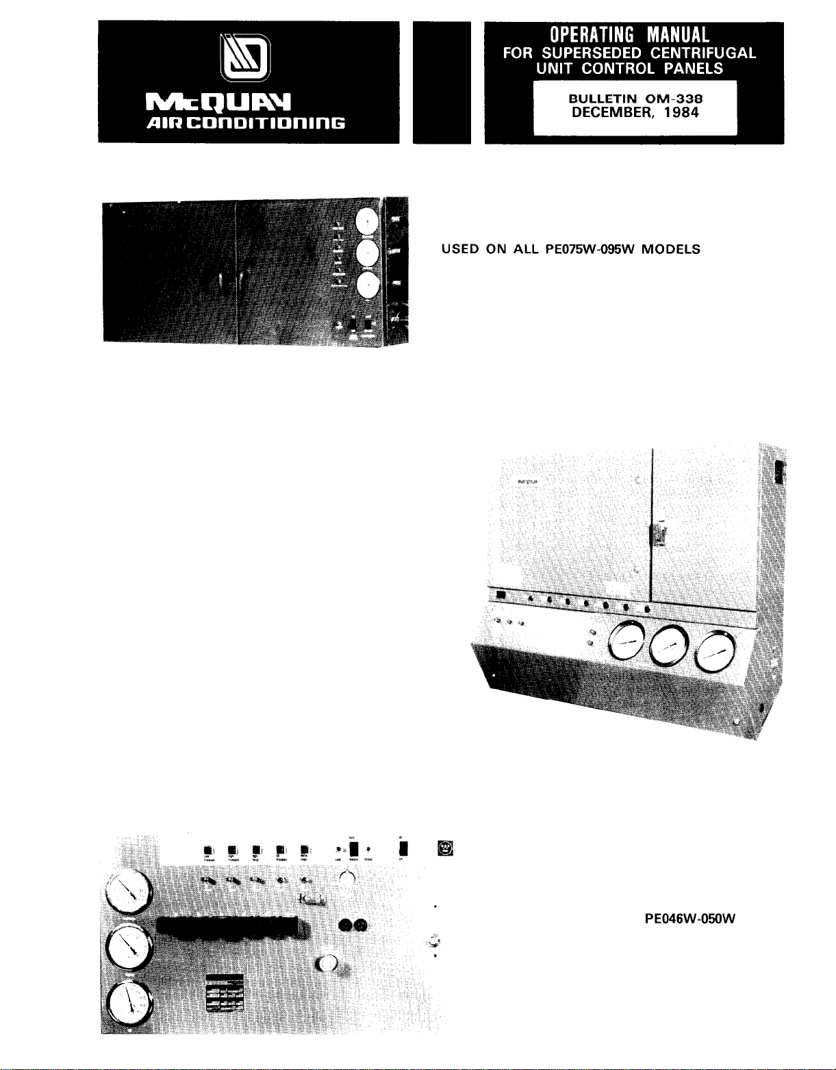
PE046W-06OW
31,1982
Page 2

GENERAL
Prior to January 1, 1982 a number of different control
panels were utilized on the model PE and PF centrifugal water chilling units. None of these panels are
now in production, this bulletin will provide general
information on these superseded panels to assist service personnel in understanding the operating sequence as well as providing control settings and
functions.
Each unit control oanel contained necessarv
operating
and
1.
Leaving Water Cycling Thermostat (CT or LRT)
2.
Guardistor Motor Protection
High Pressure Cutout (HP)
3.
4.
Low Pressure Cutout
5.
Oil Pressure Differential Switch (OD)
6.
High Oil Temperature Thermostat (OT or HOT)
7.
Vane Closed Switch (VD)
8.
Low Pressure Override Switch
9.
Oil Pump Time Delay Relay (OTD)
10.
Oil Pump Motor Capacitor
11.
Oil Pump Motor Contactor
Oil Pump Motor Overload Relays (OL)
12.
Electronic Control Module (Temperature and
13.
Current)
Generally, control item identifications and identifying
symbols on wiring diagrams were maintained the same
from panel to panel; however, there were cases where
a control with the same function did carry a different
symbol than had been used on similar panes of an
earlier design. The table of operating and safety controls starting on page 14 will identify controls and also
show where differences did exist.
Notes
1.
2.
3.
-
The information following is of a general nature
and applies to all control panels illustrated on
pages 4 through 6, except for the temperature/
motor load control modules. Details on the different control modules which were used are presented starting on page 7.
When functions covered by a specific control panel
differ from the write-up below, these differences
will be covered with the control panel details on
pages 4 through 6.
A control summary table is presented starting on
page 14, the summary contains the control identifications and other details of protection and operating controls used in the panels.
controls.
All panels basically included:
(GR)
(LP)
(LPO)
(1
M)
protective
OPERATING SEQUENCE
The following operating sequence generally applies to
control panels built through January 1, 1982. Informa-
/l/82
tion on panels utilized after 1
rent product manuals.
Assuming all interconnecting control and power wiring
connections to the panel are complete and the
off” switch is in the “on” position, the operating
controls will be allowed to call for unit operation.
is contained in cur-
“on-
NOTE
If power to the control panel is supplied
by a separate transformer, it should be
rated 2KVA with an inrush rating of
The disconnect switch in the power lines
supplying this transformer must be marked
to prevent the switch from being opened
and de-energizing the control circuit. Oil
heaters are required whenever the unit is
shut down. It is most important that power
is available to the heaters at all times the
unit is not operating.
An open section in the control circuit has been
provided for connection of chilled and condenser
water pump starter interlocks and flow switches.
The purpose of these interlocks is to prevent the
compressor from starting unless both chilled and
condenser water pumps are running and flow has been
established.
The cycling thermostat with its control bulb located in
the leaving chilled water line will, when cooling is required, close its contacts and energize the starting
sequence built into the control panel (assuming the
chilled water pump is running and flow has been established) closing of the cycling thermostat contacts will
first call for oil pump operation by energizing the pump
motor contactor and the oil cooler solenoid valve
through the clutch coil contacts on the oil time delay
relay (OTD).
Once the oil pump is running, two switches and a
timing relay must be satisfied before the compressor
will be allowed to start.
1.
The oil pressure differential switch will close when
the oil/suction pressure difference is 50 psig or
greater. If adequate oil pressure is not developed,
this switch will not close and the compressor will be
prevented from starting.
Before the compressor can start, the inlet guide
vanes must be closed. The vane closed position is
sensed by a pressure switch which is activated
when the unloader piston has moved the guide
vanes to the fully closed position
capacity). Until the vanes are in the minimum
load position, the compressor starting position in
the control circuit will not be energized.
The control circuit also incorporates a timing relay
(OPT) which will stop the oil pump if adequate oil
pressure is not developed or the compressor does
not start within 60 seconds from the closing of the
cycling thermostat.
Once adequate oil pressure has been developed and
the oil differential and vane closed switches have
closed, the condenser pump will be energized by the
condenser pump relay contacts (HWR). The condenser pump must cycle with the compressor. A
second set of condenser pump relay contacts com-
plete a circuit to the motor control relay(s) (MCR),
energizing it or them and as a result energizing the
compressor motor starter to bring the compressor on
line.
Once the compressor is running, the temperature
control module will direct the opening or closing of
the compressor suction inlet guide vanes as requirements for more or less cooling are relayed by the
sensor located in the leaving chilled water line.
12KVA.
(10
percent
2
Page 3

In addition to temperature, the current section of the
control module is constantly monitoring the amount of
current being drawn by the compressor motor. The
current limit is manually set for the required current
limit level (percent of rated load amperes). Regardless
of demands for added cooling capacity, the current
sensing section of the module will not permit the
compressor vanes to open beyond the point where
added capacity will require a value of motor current
which would exceed the current limit setting.
When load conditions change and the need for less
cooling is relayed to the temperature control section
through the sensor in the leaving chilled water, compressor capacity will be reduced as the building
load drops. When the compressor has been unloaded
to 10 percent and the load continues to fall, leaving
chilled water temperature will also drop until the
setting of the cycling thermostat is reached
below design leaving water temperature), at this point
the contacts in the cycling thermostat will open and
the following sequence will take place:
1.
The condenser pump relay will be de-energized
and the condenser pump will stop.
The motor control relay will be de-energized,
2.
opening the compressor starter contacts and stopping the compressor.
The oil pump will continue to run for an additional
3.
30 seconds after the cycling thermostat contacts
open. Keeping the oil pump running after the compressor has stopped will accomplish the following:
a. Bearing lubrication is assured during the spin-
down period.
b. If the compressor cycled off before the vanes
were at minimum load position, the unloading
piston will be driven toward the minimum load
position. (The vanes must be at the minimum
load position before the compressor can start
on the next call for cooling.
4.
The compressor and oil sump heaters are energized
and stay on until the compressor starts again.
5.
A timing relay is incorporated into the control circuit to limit compressor starts to not more than one
every 40 minutes (timed from start). If the com-
pressor operating period prior to shutdown was
less than the time setting, it will be necessary for
the time remaining on the timer to elapse before
the compressor will be permitted to restart. If the
running time prior to shutdown was equal to or
greater than the time setting, the compressor will
be permitted to restart any time the cycling thermostat calls for cooling. A second type of relay was
used on later units where a 20 minute interval from
stop to start was utilized.
In
the event of a power failure during compressor
operation, the compressor bearings will be protected
by oil stored in the emergency cylinder. The spring
loaded piston in this cylinder will force oil into the
various lubrication passages and assure that all bear-
ings are lubricated during the
The exception to the above paragraph is the
through 135W units. These units utilized a solenoid
valve “SD” and condensing pressure to force oil
from the supply line,oil filter and oil cooler into
the compressor bearings.
GUARDISTOR
The compressor motor is protected by the Guardistor
MOTOR PROTECTION
)
spindown
period.
(3’F
PE095W
motor protection circuit. This circuit utilizes thermistors buried in the motor winding to sense temperature changes. At a preset temperature the resistance of the thermistor increases rapidly, this increase
in resistance and the resulting voltage drop causes the
guardistor relay to open and in turn to de-energize
relay
“Rl”
which opens the operating circuit and
energizes motor control relay (MCR).
The Guardistor circuit, once opened, requires manual
resetting before the compressor can be restarted. If
power to the control panel is interrupted for any
reason, the circuit will open and will have to be
manually reset once power is restored to the control
panel.
CAPACITY CONTROL MODULE
The capacity control module, regardless of the type
incorporated in the control panel, will perform the
functions described below. Where a given control
performs in a different manner, the differences will
be covered with details for that particular module
starting on page 7.
The control module is powered from a 5 volt supply
(through a current transformer and resistor located in
the compressor starter).
The control in response to signals relayed from a sen-
sor located in the leaving chilled water will regulate
compressor capacity by opening and/or closing two
solenoid valves “SA” (unload) and “SB” (load).
Opening and/or closing these valves permits oil pres-
sure to build up or drain from opposite ends of a
cylinder containing a floating piston. The compressor
suction inlet guide vanes are linked to the piston and
are positioned by moving it in one direction or the
other until the vane opening is adequate to satisfy
the load requirements.
The temperature control module on a call for increased
cooling capacity can continue to open the suction inlet
vanes until current drawn by the motor reaches the
setting of the current limit control. Once this current
value is reached, the current limit section of the control
will not permit additional loading of the compressor.
The current limit is adjustable from 40 to 100 percent
of rated load current.
The temperature controller can increase or decrease
compressor capacity through solenoid valves
and “SB”.
follows.
Loading
Unloading
Holding
Some older units included solenoid valve “SC”, this
valve was actuated by a low pressure switch and was
utilized to override the normal control and unload the
compressor on a sudden drop in suction pressure,
such as might be caused by a slow opening or sticking
expansion valve. On later units the “SC” valve was
eliminated and the low pressure override switch
actuated valve “SA” directly.
Most of the later panels included a service switch to
permit override of the capacity control and allow
manual control of compressor load level. This switch
has been included as a tool for the service mechanic
and should not be utilized for any other purpose.
3
The valve action to load or unload is as
-
SB energized, SA de-energized
-
SA energized, SB de-energized
-
SA and SB de-energized
de-
“SA”
Page 4
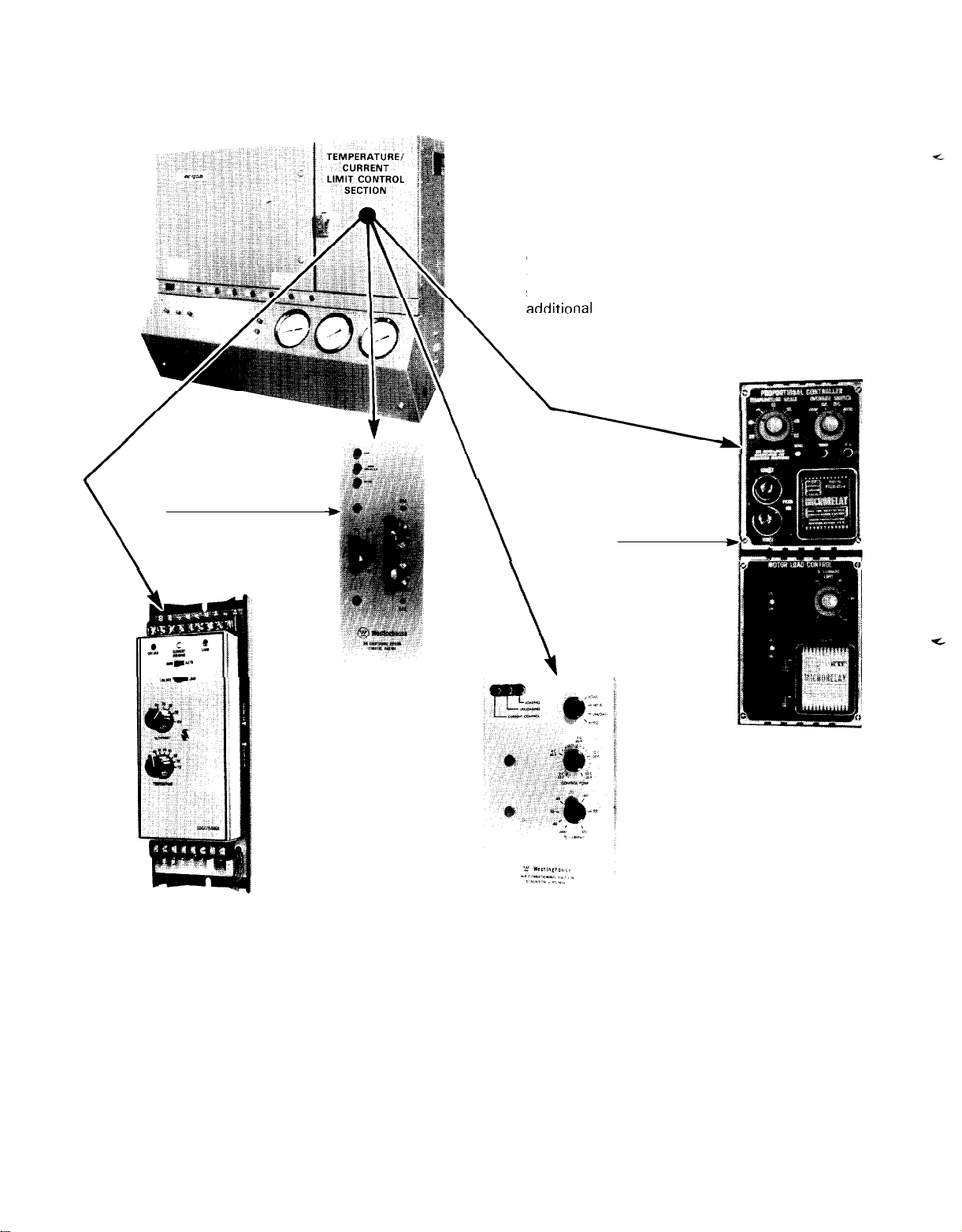
Control Panels Used on Models
Through December
SOLID STATE
TEMPERATURE/CURRENT
LIMIT CONTROLLER
SEE PAGE 8
_,
PE063,079,100
31,1982
During the production life of this control
panel improvements were made. Among
these improvements were a number of
different temperature/current limit control
modules. The different modules used are
shown below with page references for
\
AND 126
ial
information.
TUBE TYPE
TEMPERATURE/
CURRENT LIMIT
CONTROLLER
SEE PAGE 7
NOTE
*%mii
I
SOLID STATE
TEMPERATURE/CURRENT
LIMIT CONTROLLER
SEE PAGE 11
1.
Panel power supply - l-60-1 15V
2. Disconnect switch in power supply to the control
panel must be on at all times. The oil heaters
receive power through this panel.
3. If panel power is supplied through a transformer,
it must have a minimum rating of 2 KVA with an
inrush of 12 KVA.
4. All panels incorporate a timer to limit starts to a
maximum of three (3) in a two hour period. (40
minutes between starts). Later panels 20 minutes
between stop and start.
5. Earlier versions of this panel included a high
discharge temperature cutout (“HDT”).
SOLID STATE
TEMPERATURE/CURRENT
LIMIT CONTROLLER
SEE PAGE 9
6. Later versions included a low oil temperature cutout
(“LOT”).
7. Later versions included a system monitor relay and
indicating light. The system monitor was utilized to
indicate a problem in the system external to the unit
control box. For example, the compressor starter
open because its overload relays have tripped.
8. Protection against damage caused by compressor
surging was added and a lockout relay and indicating light was incorporated on later versions of the
panel. This was labeled “Surg Gard”.
4
Page 5
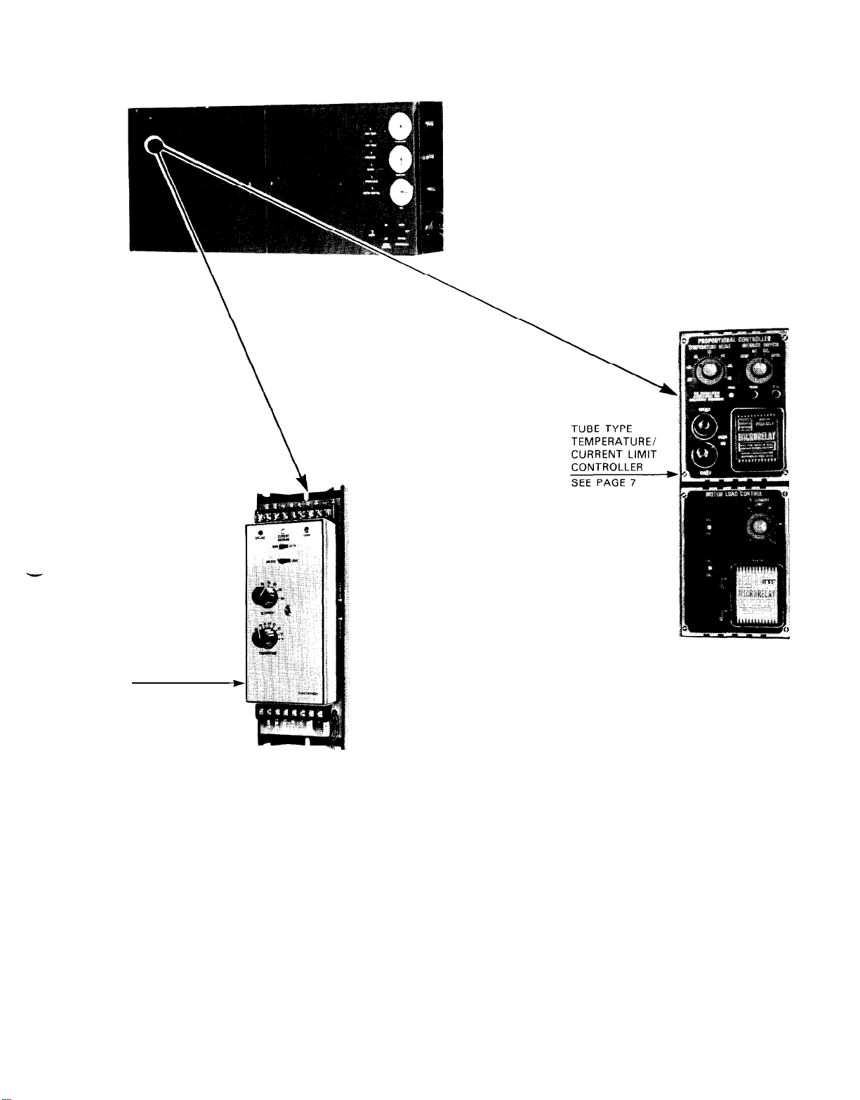
This Control Panel was used on all models PE075W through 135W units produced.
SOLID STATE
TEMPERATURE/
CURRENT LIMIT
CONTROLLER
SEE PAGE 11
THIS CONTROL
MODULE IS USED
AS A RETROFIT
DEVICE TO
REPLACE THE
ORIGINAL TUBE TYPE WHICH IS
NO LONGER AVAILABLE.
1. Panel power supply - 1-60-l
15V
2. The disconnect switch in the power supply to the
control panel must be on at all times. The oil
heaters receive power through this panel.
3. If panel power is supplied through a transformer,
it must have a minimum rating of 2 KVA with an
inrush of 12 KVA.
4. The control panel includes a time delay relay
limit compressor motor starts to a maximum of
three (3) in a two hour period. (40 minutes between
starts.
)
to
5. Panel includes a compressor start time delay relay
(CTD) which is set for 5 seconds. This permits oil
pressure to build up and bearings to be lubricated
prior to having the compressor start.
6. The compressor is protected during
spindown
after a power Failure by solenoid valve “SD”.
This is a normally open valve when its coil is
de-energized with this valve open condenser gas
pressure forces oil from the oil supply line and
compressor oil passages to assure bearing lubrication.
5
Page 6

Control Panel used on all Model PF and all model
Single and Dual Units Produced through December
PEO46W
through
31,1982.
PE06OW
THIS CONTROL MODULE
HAS BEEN USED WITH
THIS CONTROL PANEL
AS A RETROFIT DEVICE.
SEE PAGE 11
1.
Panel power supply - 1-60-l 15V
CONTROL MODULE IS MOUNTED
AT REAR OF CONTROL PANEL
BUT IT CAN BE ADJUSTED
FROM THE FRONT.
SEE PAGE 10
2. The disconnect switch in the power supply to the
control panel must be on at all times. The oil
heaters receive power through this panel.
3. If panel power is supplied through a transformer, it
must have a minimum rating of 2 KVA with an
inrush of 12 KVA.
4. All panels include a timer to limit starts to a
maximum of three
(3)
in a two hour period
(40
minutes between starts).
THIS CONTROL MODULE IS
MOUNTED AT THE REAR
OF THE CONTROL PANEL
ACCESS FOR ADJUSTMENTS
REQUIRES THAT THE REAR
PANEL BE REMOVED.
SEE PAGE 9
5. The cooling tower pump motor must cycle with
the compressor (lead compressor on dual com-
pressor units.) The control panel control circuit has
capacity to accomodate a pump motor starter
holding coil or relay with a maximum rating of
10 volt amperes.
6. All interlock contacts must have a minimum rating
of 5 amperes.
7. The alarm circuit will accomodate a load not
ceeding 10 volt amperes.
6
ex-
Page 7

TUBE TYPE (0.45 TO 0.5 VOLTS)
CURRENT LIMIT CALIBRATION
1.
Turn the current limit adjustment clockwise past the 100
percent setting until it hits
the stop.
2.
With the unit running check
the leads on the line side of
the starter to locate the phase
carrying the greatest current.
Attach the ammeter to this
phase. (Remember if the
compressor starter is a star/
delta type, the load side leads
will carry phase current. In
addition, depending on the
method used to wire the line
side it may also be possible
to read phase current on both
sides of the contactor. Phase
current.) Before attempting to calibrate this controller, be sure you know which current you are
reading.
When the compressor motor is drawing rated load
3.
amperes,
the current
resistor combination located in the compressor
motor starter should provide a voltage between
0.45 and 0.5 volts to the control module. If you
are reading phase amperes, line amperes can be
calculated. Line amperes = Phase amperes x
1.732.
4.
The selector switch located to the right of the
temperature adjustment can be used to increase or
decrease compressor load. Using the switch gradually increase the motor load to 105% of rated
load amperes.
the 100% point turn, the “CR1 and
screws all the way clockwise. With these adjust-
ment screws all the way clockwise the current
limit controller is prevented from functioning.
It may not always be possible to load the
compressor to rated load amperes because
of system loading conditions. When this
condition exists, see Section 9 below.
5.
With the compressor drawing 105% of rated load
amperes, slowly turn the
counter clockwise
the cover of the micro-relay is removed the action
of the “CR1 and
6.
Readjust the load on the compressor to reduce the
current drawn to 100% of rated load amperes. At
this point slowly turn the
counterclockwise
7.
Allow the unit to continue operating for a period of
time and recheck the settings of “CR1 and CR2”.
When checking the
necessary to temporarily place a jumper across
terminals “D and E”. (If this jumper is not used,
the compressor will not load beyond 100%
After relay “CR1 and CR2” adjustments are verified
8.
current equals 58% of line
transformer/adjustable
(If
the module will not load beyond
CR2”
adjusting
NOTE
“CRI”
adjusting screw
until the relay energizes. (If
CR2”
relays can be observed.)
“CR2”
adjusting screw
until the relay energizes.
“CR2”
adjustment it will be
1.
remove the jumper between terminals “D and E”
and turn the current limit adjustment knob clockwise against the stop. Loosen the set screw in the
knob and adjust the knob to indicate 100% and
retighten the set screw.
At times the system load may not be adequate to
9.
allow compressor loading to rated load amperes.
When this condition is encountered, reduce the
current limit controller to an obtainable current
value. Using this reduced current, the calibration
currents can be calculated as shown below.
Example -- Assume a unit with a nameplate rated
load ampere value of 400 and an operating load
condition that will not allow loading the compressor
beyond 320 line amperes.
Calculate the percent of full load setting amperes
at the operating condition.
Load
Settrng %
,Load
Amps.
Avail.-(.OSxRated
Rated Load Amperes
z
320 - (.05x400) xl 00
zz
320 - 20 =
400
759’0
400
Load
Amps)xlOO
Calculate the calibration amperes
“CR2”
calibration amperes =
“CR 1” calibration amperes=CR2+(.05xRated
0.75xRated
=
0.75x400 = 300 amps.
=
300+(.05x400) = 320 amps
Load Amperes
Load Amperes)
If phase amperage is being read, it will be
necessary to adjust the calibration amperes. Proceed as shown below.
1.
Rated Load Phase Amperes
=
0.58 x Nameplate Rated Load Amperes
= 0.58 x 400 = 232
2.
Phase Amperes at Load Condition should equal
%
of rated load amperes =
3.
4.
“CR2”
phase current calibration amperes = Rated
320 x 0.58 = 185.6
Phase
Rated Load Phase Amperes
= 185.6 x 100 = 80%
232
Amperes x 100
load phase amperes x % of rated load amperes =
232 x
.80
= 185.6
5.
“CRl”
phase calibration amperes = rated load
phase amperes xl
.05 =
185.6 x 1.05 = 194.9.
TEMPERATURE CALIBRATION
1.
Set the temperature control knob to indicate the
required design leaving water temperature.
2.
With the unit operating adjust the unit capacity
until the required design leaving water is indicated on the thermometer located in the chilled
water leaving the chiller. Allow the unit to run
until the temperature has stabilized at the proper
temperature. Check the temperature adjustment
knob, if it is not reading the same as the leaving
Page 8

water, loosen the set screw and set the knob to
read the correct temperature.
3.
This temperature control module requires the use
of a leaving water temperature sensor part number
350A160HOl
950 ohms at a temperature of 45°F. See Figure
10B. Page 12 for additional temperature vs. re-
sistance relationships for the sensor.
4.
If the panel surrounding the control module does
not have two plug buttons or holes located at about
the center line of the temperature controller, it
will be necessary to remove the grey panel sur-
rounding the control module. The plug buttons or
holes will allow access to terminals “X and T” as
will removal of the panel.
5.
Connect a voltmeter to terminals “X and T”.
(These terminals are located to the left of the temperature controller.)
With the leaving chilled water at the required tem-
6.
perature, turn the calibration adjustment (located
below the selector switch) until the lowest possible
voltage reading is obtained on the voltmeter. (This
is called the null voltage). Once this voltage
.The sensor has a resistance rating of
SOLID STATE CONTROL MODULE
sett-
ing has been determined any change in capacity
(increase or decrease) will cause the voltage to in-
crease above the null value.
Recheck the calibration by rotating the temperature
7.
set point adjustment knob slowly back and forth.
The lowest voltage reading should be obtained
when the dial reading agrees with the thermometer
at the leaving water sensor.
8.
With the voltmeter still connected to terminals
“X and T” the sensitivity can be adjusted.
Set the temperature control to the design
a.
conditions.
Turn the manual selector switch to the stop
b.
position.
Adjust the control point knob to obtain the
C.
lowest voltage reading possible.
Adjust the sensitivity screw to obtain the lowest
d.
possible voltage reading.
Remove the voltmeter and return the selector
e.
switch to the auto position and adjust the
temperature control to the design point.
CURRENT LIMIT CALIBRATION
Turn the current limit adjust-
ment
until it hits the stop just past
100% current limit.
With the unit running, check
the leads on the line side of
the starter to locate the phase
carrying the greatest current.
Attach the ammeter to this
phase. (Remember if the
compressor starter is a star/
delta type, the load side leads
will carry phase current.) In
addition, depending on the
method used to wire the line
side, it may also be possible
to read phase current on both
sides of the contactor. Phase
current
rent.) Before attempting to calibrate this controller, be sure you know which current you
are reading.
With the compressor motor drawing rated load
amperes, the current transformer/adjustable resister combination located in the starter should be
delivering a 5 volt signal to the control module. If
you are reading phase amperes, line amperes can
be calculated. Line Amperes = Phase Amperes,
x 1.7322.
Proper calibration of the current limit section of
the control module requires that the calibration
take place in steps. Begin to load the compressor
until the ammeter reads 40 percent of rated load
amperes, adjust the current limit calibration screw
until both the load and unload lights are out and the
amber light is on. Progressively load the machine
to 60, 80, and 105 percent and follow the same
calibration procedure at each load level. Continue
to watch the ammeter reading with the compressor
knob
clockwise
=
58% of line cur-
motor drawing 105 percent of rated current and
allow the compressor to continue running. Make
any fine adjustments required during this operating
period.
Leave the current limit control against the stop.
5.
Loosen the screw securing the knob to the shaft
and reinstall the knob so the 100 percent current
limit indication is against the stop and retighten the
locking screw. The current limit control is now
calibrated.
TEMPERATURE CALIBRATION
1.
Turn the unit control point to indicate the required
design leaving water temperature.
This temperature control module requires the use of
2.
a leaving water temperature sensor part number
350A160H04.
55F. The sensor has a resistance rating of 40,700
ohms at a temperature of 45°F. See Figure
Page 12 for additional temperature vs. resistance
relationships for the sensor. If temperature is in the
range of 20°F to
This sensor has a resistance of 1380 ohms at 45°F.
See Page 13, Fig. 1 1 B for additional relationships.
With the unit operating, adjust the unit capacity
3.
until the required design leaving water temperature
is indicated on the thermometer located in the
chilled water leaving the chiller. Allow the unit
to run until the temperature has stabilized at the
proper temperature.
4.
Once the design leaving water temperature is
obtained, adjust the temperature calibration screw
until both the load and unload lights remain out.
Allow the machine to continue to run at the
5.
stabilized leaving water temperatures, if an addi-
tional adjustment in calibration is required. Make
it as described in Step 4.
Remove the control point knob and reinstall it to
6.
indicate the correct leaving water temperature.
for temperatures between 35 and
4o”F,
use sensor number
35OA160H08.
10A,
8
Page 9

SOLID STATE CONTROL MODULE
CURRENT LIMIT
side, it may also be possible to read phase cur-
rent on both sides of the contactor. Phase
current = 58% of line current.) Before attempting to calibrate this controller, be sure you know
which current you are reading.
With the compressor motor drawing rated load
amperes, the current transformer/adjustable resister combination located in the starter should be
delivering a 5 volt signal to the control module.
If you are reading phase amperes, line amperes
can be calculated. Line Amperes = Phase Amperes
x 1.7322.
Proper calibration of the current limit section of the
control module requires that the calibration take
place in steps. Begin to load the compressor until
the ammeter reads 40 percent of rated load
amperes, adjust the current limit calibration screw
until both the load and unload lights are out and
the amber light is on. Progressively load the
machine to 60, 80, and 105 percent and follow
the same calibration procedures at each load level.
Continue to watch the ammeter reading with the
CALIBRATION
Turn the current limit
adjustment knob clockwise until it hits the stop
just past 100% current
limit.
With the unit running,
check the leads on the
line side of the starter
to locate the phase carrying the greatest current. Attach the ammeter to this phase.
member if the compressor starter is a star/
delta type, the load side
leads will carry phase
current.) In addition, depending on the method
used to wire the line
(Re-
compressor motor drawing 105 percent of rated
current and allow the compressor to continue running. Make any fine adjustments required during
this operating period.
5.
Leave the current limit control against the stop.
Loosen the screw securing the knob to the shaft
and reinstall the knob so the 100 percent current
limit indication is against the stop and retighten
the locking screw. The current limit control is now
calibrated.
TEMPERATURE CALIBRATION
1.
Turn the unit control point to indicate the required
design leaving water temperature.
2.
This temperature control module requires the use
of a leaving water temperature sensor part number
350A160H07
The sensor has a resistance rating of 2215 ohms at
a temperature of 45°F. See Figure 1 1 A, Page 13 for
additional temperature vs. resistance relationships
for the sensor. If the sensor operating temperature
is between 20 and 40°F a sensor part number
350A160H08
resistance of 1380 ohms at 45°F. See Figure 1 1 B,
Page 13 for additional information.
3.
With the unit operating, adjust the unit capacity
until the required design leaving water temperature
is indicated on the thermometer located in the
chilled water leaving the chiller. Allow the unit
to run until the temperature has stabilized at the
proper temperature.
4.
Once the design leaving water temperature is obtained, adjust the temperature calibration screw
until both the load and unload lights remain out.
5.
Allow the machine to continue to run at the
stabilized leaving water temperatures, if an addi-
tional adjustment in calibration is required. Make
it as described in Step 4.
6.
Remove the control point knob and reinstall it to
indicate the correct leaving water temperature.
for temperatures between 35 and 55F.
will be required. This sensor has a
OLD
PF SOLID STATE CONTROL MODULE
GENERAL
1.
All adjustments to the
control module will require removal of the
rear panel from the con-
trol box.
2.
Calibration of both current limiting and temperature are made at
the rear of the control
box.
3
With the
motor drawing rated
load amperes the current transformer/adjust-
able resistor located in
the motor starter should
be delivering a 5 volt
signal to the control module. If you are read-
compressor
phase amperes line amperes = Phase amperes x
1.732.
4.
Adequate adjustment of the current limit and
temperature sections of the control module will
require that load and unload indicating lights be
added to the unit. These lights should be tied in
parallel with the load and unload solenoid valves.
A green light (load) should be tied in parallel with
solenoid “SB” and a red light (unload) in parallel
with a solenoid “SA”. Older model units will have
two separate solenoids. Later units will have a com-
4-way
bination
newer units the valves will be located in a box
on the rear of the compressor.
valve with two solenoid coils. On
CURRENT LIMIT CALIBRATION
1. The current limit section of the control module
should be set to limit the current drawn by the
9
Page 10

compressor to 105 percent of rated load amperes.
This adjustment should be made in steps to ensure
proper setting at the recommended 105 percent
level.
The model PF unit is generally supplied with Star/
2.
Delta starters mounted and wired. With the compressor running, check the leads on the line side of
the starter. Up through 164 amperes you may find
three power leads supplying the line of contactor
#l
Number 1 with jumpers from Contactor
tactor #2.
three leads from the disconnect to Contactor 1
should read line amperes. Above 164 amperes, the
starter will have 6 leads from the disconnect to
the starter, 3 leads will be connected to Contactor #I
connected to these leads will read phase amperes.
To check whether you are reading line or phase
amperes on a star/delta starter, check the amperage on any of the six leads on the motor side of the
starter, the ammeter will read 58 percent of line
current. If the line and load side of a star/delta
starter have the same ampere reading, you are
reading phase amperes.
Adequate calibration of both the current limit and
3
temperature section of the control module will
require that indicating lights be added to each con-
trol panel. When adding these lights they should be
tied in parallel with the load (SB) solenoid and un-
load
indicate that the machine is loading, a red light
to indicate it is unloading.
4.
Attach an ammeter to the phase on the line side of
the starter carrying the greatest current.
After the indicating lights have been added, reduce
5.
the setting on the current limit controller close to
its minimum point and gradually load the com-
pressor until both indicating lights are out. Read
the ammeter at this point and establish the percent
of rated load current being drawn. (For this
An ammeter connected to any of the
and 3 to Contactor
(SA)
solenoid. A green light is suggested to
#2.
An ammeter
to Con-
illustration assume it is about 70 percent.) Increase
the setting on the load limit control and gradually
load the machine by increasing the compressor load
and the setting of the current limit controller
until the ammeter reads approximately 90 percent
of rated load current and both of the indicating
lights are out. Repeat this procedure once more
until the compressor is drawing 105 percent of
rated load amperes.
Allow the compressor to continue running and
make any adjustment in the load limit that may be
required to keep the indicating lights out when the
compressor is drawing 105 percent of rated load
amperes.
Reduce the load on the compressor and attempt
to reload beyond ammeter reading equivalent
to 105 percent of rated load amperes. When the
current limit control is correctly adjusted, the
load indicating light will go out with the ammeter
indicating a current draw equivalent to 105 percent
of rated load amperes.
TEMPERATURE CALIBRATION
1.
This temperature control module requires the use
of a leaving watertemperature sensor, Part Number
350A160H04.
of 40,700 ohms at a temperature of 45°F. See
Figure
versus temperature relationships for the sensor.
2.
Calibration of the temperature sensor is also made
through the rear of the control box. Check the
thermometer located in the leaving chilled water
and adjust the temperature until the required design
water temperature is obtained. At this point both
the load and unload lights should be out; if they
are not, move the temperature adjustment screw
until both lights remain out.
3.
Allow the unit to continue to operate and make any
fine adjustments required during this period.
The sensor has a resistance rating
IOA,
Page 12 for additional resistance
PF
SOLID STATE CONTROL MODULE (DISCONTINUED JANUARY, 1982)
GENERAL
With the compressor motor
drawing rated load amperes
the current transformer/adjustable resistor located in the
motor starter should be delivering a 5 volt signal to the con-
trol module. If you are reading
phase amperes, line amperes
= phaseamperes x 1.732.
Adequate adjustment of the
current limit and temperature
sections of the control module
will require that load and unload indicating lights be added
to the control panel. These
lights should be tied in parallel
with the load and unload sole-
noid valves. A green light
(load) should be tied in parallel
with solenoid “SB” and a red
light in parallel with solenoid
“SA”. Older units will have two separate sole-
noid valves, later units will have a single four (4)
way valve with two operating solenoid coils. On
10
newer units the valves will be located in a box
attached to the rear of the compressor.
CURRENT LIMIT CALIBRATION
1.
The current limit section of the control module
should be set to limit the current drawn by the
compressor to 105 percent of rated load amperes.
This adjustment should be made in steps to
ensure proper setting at the recommended 105
percent level. The model PF unit is generally
supplied with star/delta starters mounted and
wired, be aware of what current value you are
reading on your ammeter.
2. With the compressor running, check the leads on
the line side of the starter. Up through 164
amperes you may find three leads supplying the
line side of Contactor
tactor #I
to the three leads from the disconnect to Con-
tactor #I
amperes, the starter will have 6 leads from the
disconnect to the starter, 3 leads
to Contactor
connected to these leads will read phase amperes.
To check whether you are reading line or phase
to Contactor
should read line amperes. Above 164
#I
and 3 to Contactor
#I
with jumpers from Con-
#2.
An ammeter connected
will
be connected
#2.
An ammeter
Page 11

amperes on a star/delta starter, check the amperage on any of the six leads on the motor side of
the starter, the ammeter will read 58 percent of
line current. If the line and load side of a star/
delta starter have the same ampere reading, you
are reading phase amperes.
3.
As previously stated, adequate calibration of both
the current limit and temperature section of the
control module will require that indicating lights
be added to each control panel. When adding these
lights they should be tied in parallel with the load
(SB) solenoid and unload (SA) solenoid. A green
light is suggested to indicate the machine is
loading, a red light to indicate it is unloading.
Attach an ammeter to the phase on the line side of
4.
the starter carrying the greatest current.
After the indicating lights have been added, reduce
5.
the setting on the current limit controller close
to its minimum point and gradually load the com-
pressor until both indicating lights are out. Read the
ammeter at this point and establish the percent of
rated load current being drawn. (For this illustration
assume it is about 70 percent.) Increase the
setting on the load limit control and gradually load
the machine by increasing the compressor load
and the setting of the current limit controller
until the ammeter reads approximately 90 percent
of rated load current and both of the indicating
lights are out.
Repeat this procedure once more until the
pressor
amperes.
6.
Allow the compressor to continue running and
make any adjustment in the load limit that may be
is drawing 105 percent of rated load
com-
required to keep the indicating lights out while the
compressor is drawing 105 percent of rated load
amperes.
7.
Reduce the load on the compressor and attempt
to reload beyond an ammeter reading equivalent
to 105 percent of rated load amperes. When the
current limit control is correctly adjusted, the
indicating lights will go out when the compressor
is drawing a current equivalent to 105 percent of
rated load amperes.
TEMPERATURE CALIBRATION
Adjust the temperature control knob to indicate
the required design leaving water temperature.
This temperature control module requires the use of
a leaving water temperature sensor part number
350A160H04.
40,700 ohms at a temperature of 45°F. See Figure
IOA,
Page 12 for additional resistance versus
temperature relationships for the sensor.
With the unit operating, continue to adjust the
control until the design leaving water temperature is
indicated on the thermometer located in the water
line leaving the chiller. Allow the unit to run
until the leaving water has stabilized at the required
temperature.
Once the design water temperature is obtained,
adjust the temperature calibration screw until both
the load and unload lights are out.
Allow the machine to continue to run at the stabilized temperature, if additional fine tuning of the
calibration is required it can be done at this time.
Remove the temperature control knob and reinstall
it to indicate the correct leaving water temperature.
The sensor has a resistance rating of
SOLID STATE CONTROL MODULE (USED FOR
CURRENT CALIBRATION
1.
Start the unit and place the
control module selector switch
in the manual position.
2.
Open the starter door and place
the
amprobe
drawing the highest current on
the load side of the starter.
3.
Remove the control module
cover.
Set current demand limit selec-
4.
tor switch clockwise
the stop (100%).
Set the blue current limit cali-
5.
bration screw (located just to
the left of the temperature control stem) to the full counterclockwise position.
6. Check the compressor motor nameplate rated
load amperes
on the amprobe. Manually adjust the load until
the amperes drawn by the motor match the motor
rated load amperes. If a star/delta starter is
being used be sure you are reading line amperage.
7. When the nameplate and
are equal, turn the current limit calibration screw
clockwise until the amber light just comes on and
stop. This places the unit in current hold. The
internal circuitry of the module will now insure
that, should the current increase to 105 percent of
rated load amperes, the controller will unload the
compressor.
To verify that the calibration is correct, manually
(RlA)
against the amperage reading
on the power lead
amprobe
ampere values
against
11
REl-ROFlT
unload and then reload the compressor to the rated
load ampere value and verify that the current override light glows. The current limit control portion of
the module is now in calibration.
8.
Check the knob setting, if it needs correcting snap
the top off the control knob, loosen the screw and
rotate the knob to indicate 100% of current.
Tighten screw and replace top.
TEMPERATURE CONTROL CALIBRATION
1.
Remove control module cover.
2.
Allow unit to operate until leaving water temperature stabilizes. With the thermometer located
in leaving chilled water, read the water temperature.
3.
On the control module turn the temperature control
knob to a point where both the unload (red) and
load (green) lights remain off. Move the knob to the
midpoint between these points.
4.
Check voltage between control module terminals
“IOM” and “COM” using a DC voltmeter. The
voltage reading should be close to
5.
Read the leaving water temperature once more.
Check this temperature against the temperature
indicated by the pointer at the base of the temperature control stem. If they do not agree, hold
the stem and rotate the pointer until it indicates
a temperature on the scale corresponding to the
thermometer reading.
6.
Replace the control module cover. Check the
temperature indicated by the knob against the
cover temperature scale. If the reading is not
correct, snap the top off the knob, loosen the
screw and rotate the knob until it indicates the
correct temperature. Tighten the screw and replace
the top of the knob.
ON MANY OLDER
7.5V
UNlTS)
(
f
0.5V).
Page 12

Page 13

Page 14

Page 15

Page 16

 Loading...