

Page 1
Installation & Maintenance Data
AAF–McQuay Suite™ With Top Mounted Heat Section
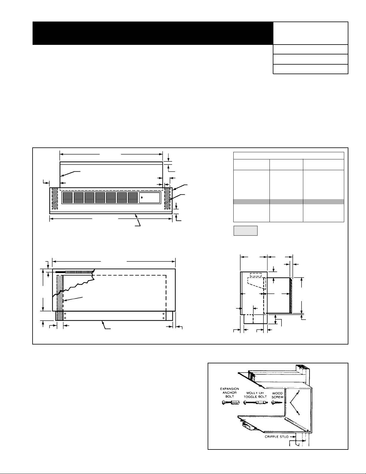
Wall Sleeve Installation
Wall Opening Requirements
Before installing the unit, check the wall opening to be sure the
wall sleeve will slide into the opening unobstructed. For masonry
walls, a lintel must be used to provide support over each opening.
Figure 1.
IM 426-1
Group: PTAC
P art No.: 106018741
Date: May 1999
1
The rough opening should measure 16
opening must be a minimum of 4" above the finished floor (including
carpeting).
/4" high X 421/4" wide. The
42"
(1069mm)
5"
(127mm)
Wall Sleeve
52" (1320mm)
Removable Cabinet
Front Panel
Note: Electrical rough-in should be located behind kickplate
(removable front) and below wall sleeve.
11⁄2"
(38mm)
191⁄2"
(495mm)
3"
(76mm) Min.
3"
(76mm)
52" (1320mm)
Wall Space For Piping Rough-in
(Typ. R.H. & L.H.)
Kickplate (Removable
Front)
31⁄2" (89mm)
1
⁄2" (13mm)
11⁄4" (32mm)
(Architectural)
Cabinet
Floor Space
For Piping
Rough-in (Typ.
R.H. & L.H.)
2" (51mm)
7
⁄8"
(22mm)
51⁄2"
(140mm)
15⁄16"
(33mm)
11/4" RECESS FOR ARCHITECTURAL LOUVER
“A”
ROOM CABINET
173/4"
163/4"
153/4"
143/4"
133/4"
123/4"
113/4"
103/4"
103/4"
103/4"
103/4"
103/4"
“B”
WALL SLEEVE
133/4"
133/4"
133/4"
133/4"
133/4"
133/4"
133/4"
133/4"
143/4"
153/4"
163/4"
173/4"
WALL THICKNESS
53/4" to 63/4"
63/4" to 73/4"
73/4" to 83/4"
83/4" to 93/4"
93/4" to 103/4"
103/4" to 113/4"
113/4" to 123/4"
123/4" to 133/4"
133/4" to 143/4"
143/4" to 153/4"
153/4" to 163/4"
163/4" to 173/4"
Standard Size Wall Sleeve
Wall
Thickness
“A”
91⁄8"
(232mm)
15⁄8"
(41mm)
“C”
27⁄8" (67mm)
“B”
3" (76mm) Min.
Kickplate Height
11⁄4" (32mm)
16"
(406mm)
7
⁄8" (22mm)
“C”
Anchoring
Figures 3 through 5 on the following pages illustrate typical wall
sleeve installations. After the wall sleeve has been set in place
anchor it in the opening as shown in Figure 2. It is recommended
that rubber isolation washers be used with the fasteners to minimize sound transmission from the equipment to the wall, at the
point of contact.
Level w all sleeve in all directions and anchor with appropriate
fasteners (as shown in Figure 2). A
side, 2" down from the top and 2" in from the rear of the wall
sleeve. It may be necessary to drill additional holes in the wall
sleeve to firmly secure it. CAUTION: Do not drill holes in the base
of the wall sleeve . Use shims between the wall and the wall sleev e
to prevent wall sleeve distortion during anchoring.
5
/16" hole is provided on each
©1999 AAF–McQuay Incorporated IM 426-1 / Page 1 (Rev. 5/99)
Figure 2.
Page 2
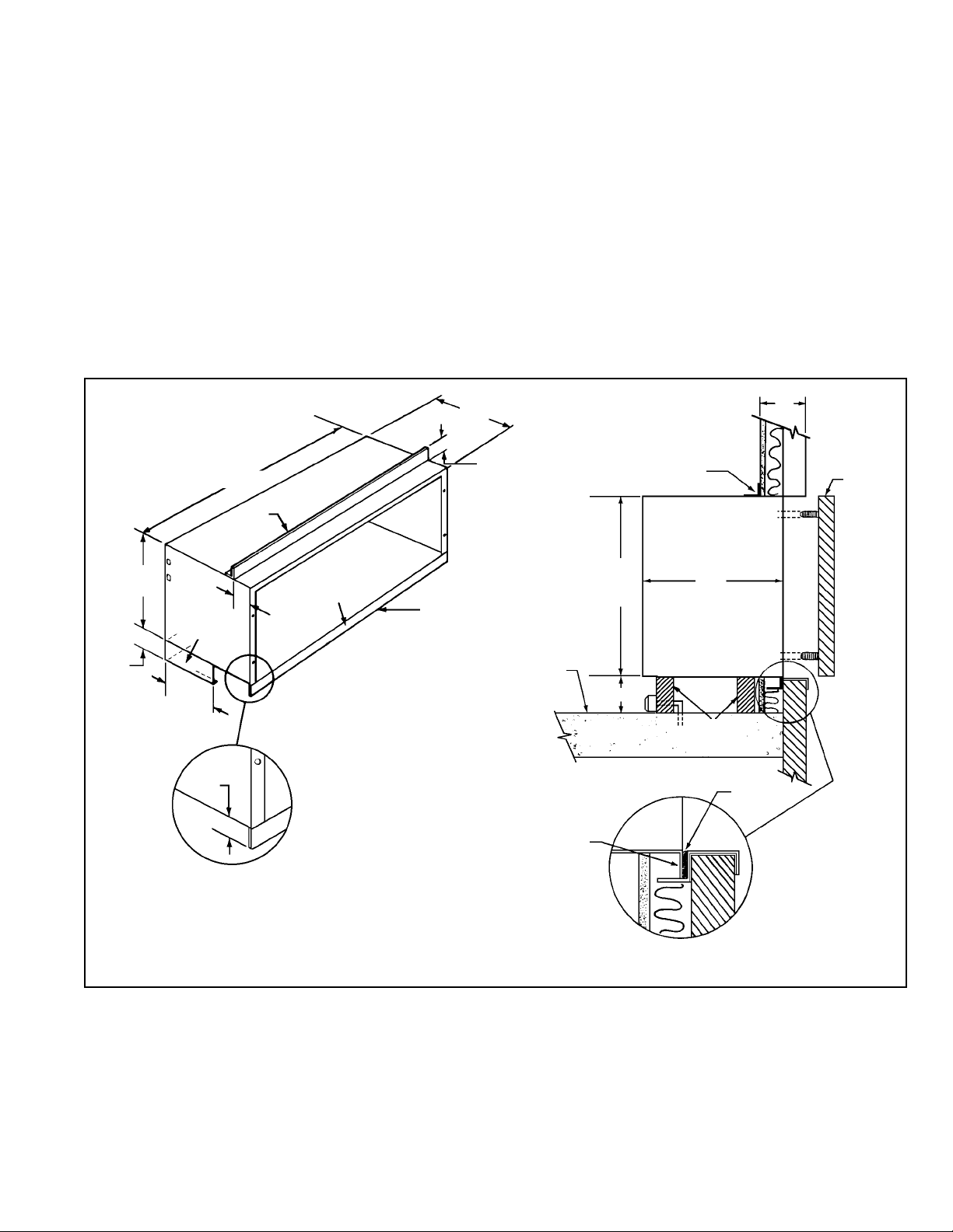
Wall Sleeve Installation – Thin Wall Construction
The standard wall sleeve is designed to be easily installed in a
variety of wall constructions. For panel wall and thin wall construction, it is recommended that the optional top angle be used
wall sleeve. If a subbase is not used, field support must be
provided up to the center of gravity. This support can be metal,
wood or concrete.
and the wall sleeve be supplied with a turned down flange
(see Figure 3).
The recommended procedure for installing units in panel wall
and thin wall construction is as follows:
3. Level wall sleeve in all directions and anchor with appropriate
fasteners. Use holes provided (see Figure 2, page 1) or drill
additional holes as required to secure firmly . Caution: Do not
drill holes in the base of the wall and the wall sleeve to
1. Clean the opening of all debris that may interfere with
prevent wall sleeve distortion during anchoring.
installation.
4. Caulk the wall sleeve to the wall opening on both the inside
2. Recess the wall sleeve so that the louver is flush with the
exterior of the building (refer to Figure 3). The center of grav-
and outside perimeter. This can be done from the inside of
the building. Be careful not to plug the weep holes.
ity is approximately 10 3/4" from the rear face of the standard
Figure 3. Wall Sleeve Installation Using Top Angle & Factory Supplied Louver
131⁄4"
(337mm)
42"
(1069mm)
Optional
Top Angle
Wall
Sleeve
11⁄4" (38mm)
Optional
Top Angel
C**
Outside
Louver
16"
(406mm)
Y*
Optional
Subbase
3"
(76mm)
Min .
Notes:
** See Figure 1, page 1, for dimensions “B” and “C”.
* Dimension “Y” is field determined or specified. Angle is factory welded at
101⁄2"
(267mm)
Max.
1"
(25mm)
given dimension when option is designated.
Turndown
Flange
(See Detail)
Outside
Edge of
Sleeve
Fininish Floor
Including Carpet
Turndown
Flange
16"
(406mm)
37⁄8" (98mm)
Min.
B**
Wall Sleeve
Support
By Others
(2 Req’d).
Caulk
IM 426-1 / Page 2 (Rev. 5/99)
Page 3

Wall Sleeve Installation — Thin Wall Construction
Applications utilizing field supplied louvers require additional
considerations:
Assuming the louver meets the manufacturer’ s criteria, as stated
previously, proceed to install the wall sleeve as follows:
1. Louvers supplied by others must have 70% free area or a
pressure drop not exceeding 0.05 in. w.g. at 300 fpm face
1. Clean the opening of all debris that may interfere with
installation.
velocity , and a blade design that will not cause recirculation of
condenser air.
2. Position the wall sleeve into the w all so that it is flush with the
exterior wall. Important: If the wall sleeve has been installed
2. AAF–McQuay Incorporated does not warrant the rain and
water leakage resistance of its equipment when used with
louvers by others.
into a thick wall, make certain the wall sleeve protr udes into
the room a minimum of 1
This is to accommodate the heat section and room cabinet.
The center of gravity is 103/4" from the rear face of the
3. All louvers by others must be approved by the manufacturer
prior to installation.
standard wall sleeve. If no subbase is being employed,
adequate support for the wall sleeve up to the center of g ra vity must be provided at the jobsite. This support can be wood,
4. Be sure to install foam type gaskets on all sides of the
metal or concrete.
condenser to prevent re-circulation or bypass of condenser air .
3. Level wall sleeve in all directions and anchor with appropriate
Figure 4 illustrates a typical installation using a field supplied,
continuous louver. This method is for illustration purposes only.
Other variations may be employed as long as they meet
manufacturer’ s louver specifications listed above and so long as
adequate wall sleeve support is achiev ed. All structural supports
fasteners using holes provided (see Figure 2, page 1), or drill
additional holes as required to secure firmly . Caution: Do not
drill holes in the base of the wall sleeve. Use shims between
the wall and the wall sleeve to prevent wall sleeve distortion
during anchoring.
and fasteners (except the optional top angle and turned down
flange) are field supplied.
Installation of wall sleeves with continuous louvers is very
similar to that of applications with factory furnished louvers.
4. Caulk the wall sleeve to the wall opening on both the inside
and outside perimeter. This can be done from the inside of
the building. Be careful not to plug the weep holes.
Figure 4. Wall Sleeve Installation Using Top Angles & Field Supplied Continuous Louver
1
/8" beyond the finished wall surf ace.
(406mm)
3"
(76mm)
Min.
16"
Optional
Subbase
101⁄2"
(267mm)
Max.
(25mm)
1"
42"
(1069mm)
Optional
Top Angle
Y*
133⁄4"
(349mm)
11⁄4"
(38mm)
Wall
Sleeve
Turndown
Flange
(See Detail)
Outside Edge
of Sleeve
Finished Floor
Including Carpet
Notes:
1. Caulk entire perimeter of wall sleeve after installation.
2. Seal area between louver and wall sleeve to prevent condenser air recirculation.
3. Dimensions shown in table on page 1 do not apply to this
application.
*Dimension “Y” is field determined or specified. Angle is factory
welded at given dimension when option is designated.
(406mm)
Min. 37⁄8"
(98mm)
16"
Optional
Top Angle
Supports By Others
Insulated
Panel
Wall Sleeve
(2 Req’d.)
Sleeve
Outside Louver
By Others
Turndown
Flange
Insulated
Panel
Wall
Wall
Frame
By Others
Resilient
Caulking
Resilient
Caulking
IM 426-1 / Page 3 (Rev. 5/99)
Page 4

Wall Sleeve Installation — Thick Wall Construction
A heavy-gauge, corrosion resistant wall sleeve is provided for
each unit. The wall sleeve is either shipped in a separate carton
or shipped in a multi-pack of 15.
Typical installation for masonry walls is shown in Figure 5.
The recommended installation procedure for this type of
construction is as follows:
1. Clean the opening of all debris that may interfere with instal-
lation.
2. Be sure the unit’s center of gravity falls within the load
bearing surface of the wall. The center of gr avity f or the unit is
3
approximately 10
/4" from the rear edge of the wall sleeve. If
the center of gravity is not within the load bearing surface,
then additional support such as wood, metal or concrete must
be provided in the field.
3. Place a thin pad of soft mortar on the bottom of the opening.
Important: Make certain the wall sleeve protrudes into the
1
room a minimum of 1
/8" beyond the finished wall surface to
accommodate the heat section and room cabinet. Be sure to
recess the wall sleeve enough to accommodate outside louver . This recess is
3
/8" for stamped louvers and 11/4" for architectural louvers. The louver should be flush to e xterior surface
when completed.
4. If a brickstop is employed (as shown in Figure 5), slide the
wall sleeve into the wall until the br ickstop contacts the exterior bricks, as illustrated below. If a brickstop is not used,
slide the wall sleeve in the wall so that it extends into the
1
room a minimum of 1
/8" beyond the finished interior wall surface. This allows room to attach the heat section and room
cabinet. The wall sleeve should also be recessed enough to
accommodate the outside louver.
5. After the mortar has dried, remove the masonry suport from
the wall sleeve. Note: The wall sleeve is not intended to replace the lintel.
6. Level wall sleeve in all directions and anchor with appropriate
5
fasteners (as shown in Figure 2, page 1). A
/16" hole is provided on each side, 2" down from the top and 2” in from the
rear of the wall sleeve. It may be necessary to drill additional
holes in the wall sleeve to firmly secure it. Caution:
Do not
drill holes in the base of the wall sleeve. Use shims between
the wall and the wall sleeve to prevent wall sleeve distortion
during anchoring.
7. Caulk the wall sleeve to the wall opening on both the inside
and outside perimeter using a resilient, non-hardening caulk
such as silicone. Be careful not to plug the weep holes.
Figure 5. Wall Sleeve Installation Using Brickstops
C
5
1
⁄8" (41mm) Min.
1
[–
Outside
Louver
1
1
⁄4"
(32mm)
Optional
Brickstop
B
Wall Sleeve
⁄2" (13mm)]
16"
(406mm)
37⁄8" (98mm)
Min.
NOTES:
(1) For dimensions B and C, see table on page 1.
(2) Dimension X is “as required” and is usually sent to the factory to be welded during wall sleev e fabrication.
(3) Caulk entire perimeter of wall sleeve after installation.
Finished Floor
Including Carpet
B
X
Outside Edge
of Sleeve
Wall
Sleeve
Optional
Brickstops
42" (1067mm)
1
1
⁄4"
(32mm)
16"
(406mm)
AAF–McQuay Incorporated
4900 Technology Park Boulevard, Auburn, New York 13021-9030 USA (315) 253-2771
Printed on recycled paper containing at least 10% post-consumer recycled material.
IM 426-1 / Page 4 (Rev. 5/99)
 Loading...