

Page 1

Installation & Maintenance Data
Custom Wall Sleeve (CWS)
Introduction
The wall sleeve is a standard size 16" high, 42" wide
and 13-3/4" deep. Slide channels are factory welded into
the sleeve to facilitate easy installation and removal of
the chassis. Each wall sleeve is predrilled to match the
mounting screws of the chassis. Knockouts are provided
for the optional external drain kit used with the heat
pump models.
Figure 1. Wall Sleeve
Tinnerman Clips
Slide Channels
Note: Wall sleeve shown with optional insulation installed.
IM 880
Group: PTAC
Part No.: 6681093
Date: September 2007
All necessary fasteners are supplied to assemble the
chassis and louver to the wall sleeve.
Wall Opening Requirements
When roughing in the opening for the wall sleeve,
make certain there is sufcient clearance from the
walls and oor. The wall sleeve should be positioned
a minimum of 5/8" from the nished side wall to
accommodate the room cabinet. A minimum distance of
3" above the nished oor is required for return air.
The rough opening should measure 161/4" high x
421/4" wide. When using a louver frame, the opening
must measure 165/8" x 425/8". Louver frames should be
used for panel wall and thin wall applications to assure
positive anchoring to the wall (Figure 13). When a
subbase is used, the opening must start 3" to 4" above
the nished oor (including carpeting) to match the
height of the subbase selected. The subbase is available
in 3" or 4" heights and has adjustable leveling legs that
provide up to an additional 1" height.
A 3" or 4" subbase is required for 265V models and is
optional for 208/230V models.
Figure 2. Unit with Subbase
42" (1067 mm)
43" (1092 mm)
411/2" (1054 mm)
**
133/4"
(349 mm)
161/2"
(419 mm)
*Subbase Side Dimension:
Electric: 43/4" to 133/4" (111mm to 349mm) (See Figure 6)
Hydronic: 0" to 133/4" (0mm to 349mm) (See Figure 7)
**Subbase Height Dimension:
Electric: 3" to 4" (76mm to 102mm) with 0" to 1" (0mm to 25m) leveling screw
Hydronic: 8" (203mm) with 1/4" (6mm) to 11/4" (32mm) leveling bolts
1. Unit pictured with subbase installed. Subbase is optional on 208V and 230V
units. Subbase is standard on all 265V units and units with hydronic heat.
Hydronic subbase is ush with the front of the cabinet. Electric subbase is
ush with wall sleeve.
2. Subbase extends to front edge of unit when furnished with hydronic heat.
3. Opening needs to be 165/8" x 425/8" (422mm x 1083mm) when using a louver
frame.
4. Subbase side channels are adjustable from 43/8" to 133/4" (111mm to 349mm).
16" (406 mm)
22" (559 mm)
81/4"
(210 mm)
*
©2007 McQuay International IM 880 / Page 1 of 8
Page 2
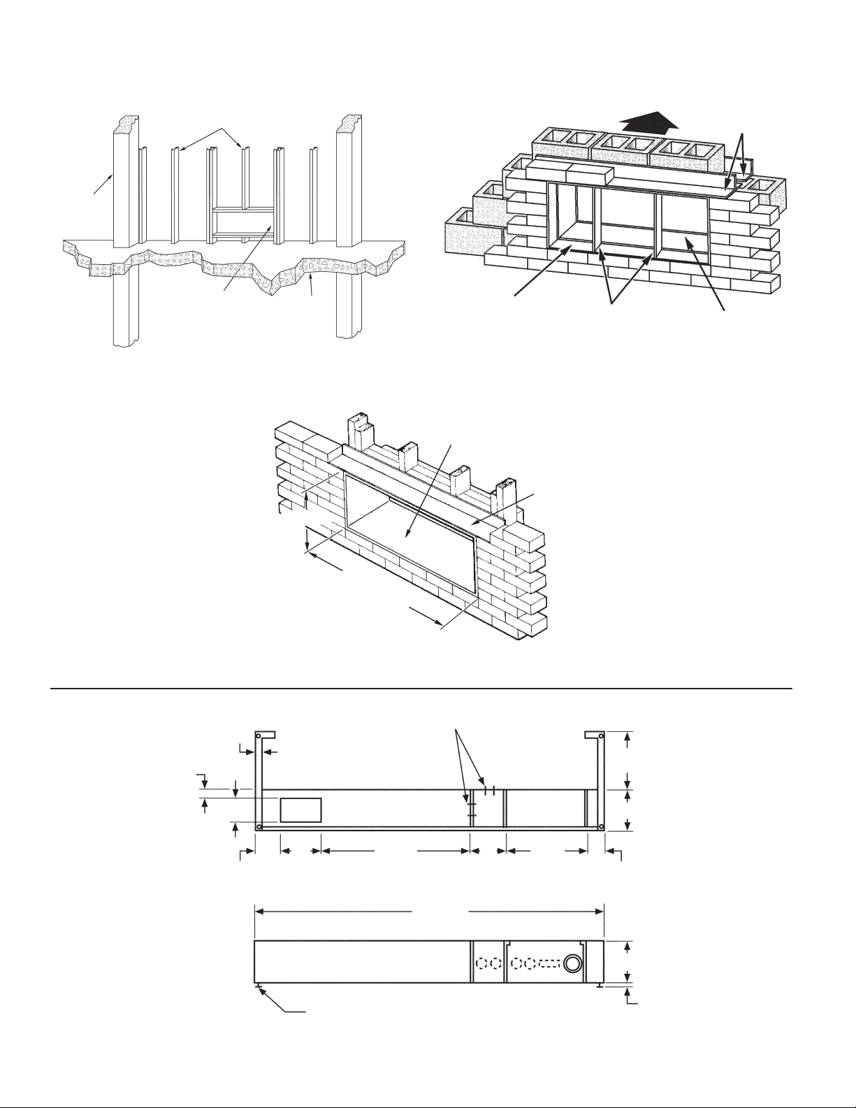
Wall Construction Types
Figure 3. Panel Wall (Thin) Construction
Steel Studs
Concrete
Pillars
161/4" x 421/4"
Wall Sleeve
Rough Opening or
165/8" x 425/8" When using
a Louver Frame
Figure 5. Frame and Brick Construction
Floor
Figure 4. Masonry Wall (Thick) Construction
Room Side
Wall Sleeve Extension
16" x 42"
Wall Sleeve
Lintel
(by others)
Splitters
Lintels (by others)
16" x 42"
Wall Sleeve
Subbases – Dimensions
Figure 6. Electrical Subbase
5
/8"
7
/8"
3"
21/2"
161/4" High
421/4" Wide Wall
Sleeve Rough Opening
5"
Electrical Knockouts
17"
Plan
411/2"
0" to 93/8"
43/8"
12"
11/2"
IM 880 / Page 2 of 8
Leveling Screw (4 Places)
Front Elevation (Three Front Panels in Place)
3"or 4"
0" to 1"
Page 3

Figure 7. Hydronic Subbase
Receptacle (Factory installed when
As Req'd
21/2"
81/4"
3/4"
15"
3" x 5" Opening for Electrical
and/or Piping Rough-in
5
/8" O.D. Copper Sweat
fuse & disconnect are furnished)
21/2"
Top View
3/4"
71/4"
Permanent
Mesh Filter
411/2"
71/2"
63/4"
Front View
Installation Requirements For Recessed
Louver Wall Sleeve
1. The Recessed Louver Wall Sleeve must extend a
minimum of 11/4" past the nished interior wall.
2. The Recessed Louver Wall Sleeve must be installed
so that it is ush with the exterior face of the building
and the drip edge must extend 1/4" beyond the face
(Figure 8).
Installing Recessed Louver Wall Sleeve
1. Clean the opening of all debris that may interfere
with installation.
2. If the unit is to be supplied with a subbase, install
subbase before installing cabinet/wall sleeve (see
IM 879).
3. lf the optional drain kit is to be employed (heat pump
only), see IM 887.
4. Place a thin pad of soft mortar on the bottom of the
opening and slide in the cabinet/wall sleeve. Louver
should be ush to exterior surface when complete.
Note: The wall sleeve is not intended to replace the
lintel.
5. Level the wall sleeve in both directions, left to right
and inside to outside, using the top of the wall
sleeve and plumb wall sleeve for vertical on the
sides.
IMPORTANT!
Do Not level base of wall sleeve. The bottom of the Recessed
Louver Wall Sleeve has a built in pitch to the outside for proper
drainage. (The inside height dimension is 15.88" and the outside
dimension is 16" to provide the necessary drainage pitch).
NOTES:
1. Side channels are adjustable from 0"–93/8" in
length by inverting them. Side channels are
predrilled to allow innite adjustment.
2. Subbase shown with louvered front panel
removed. Front panel is hinged to allow
access to valve, coil, lter & electrical
junction box.
3. Leveling legs are adjustable from 1/4"–11/4".
8"
Leveling Legs
Optional Disconnect
31/4"
11/2"
51/2"
Fuse
Electrical
Knockout
1/4" – 11/4"
End View
NOTICE
Standard Louver can not be used with recessed louver wall
sleeve. Louver is special order. Contact factory for more
information if necessary.
Figure 8. Recessed Louver Wall Sleeve Installation
Level the top of the wall
sleeve, NOT the base
of the wall sleeve (see
IMPORTANT notice)
133/4"
17"
(432mm)
See Note
Finished
Floor
or Carpet
Note: Standard subbase is available in 3" or 4" (76 mm or 102 mm)
81/4"
(209mm)
157/8"(403mm)
Room
Cabinet
Wall Receptacle
(by others)
height. Leveling legs provide adjustment of 1" (25 mm).
(349mm)
Wall Sleeve
Extends 1/4"
beyond the
exterior face of
the building
Steel Lintel
(by others)
5/16" (8mm)
Anchor Hole
16"
(406mm)
Drip Edge
Detail
IM 880 / Page 3 of 8
Page 4

6. Secure by anchoring with appropriate fastener(s).
A 5/16" (8mm) hole is provided on each side, 2"
(51 mm) down from the top and 2" (51mm) in from
the rear of the cabinet/wall sleeve. Additional holes
may be required to rmly secure the cabinet/wall
sleeve (Figure 9).
CAUTION
DO NOT drill holes in the base of the cabinet/wall sleeve.
Figure 9. Anchoring the Wall Sleeve
Rubber Isolation
Washer
Expansion
Anchor Bolt
Molly or
Toggle Bolt
Wood
Screw
2. If the unit is to be supplied with a subbase, install
subbase before installing cabinet/wall sleeve (see
IM 879).
3. lf the optional drain kit is to be employed (heat pump
only), see IM 887.
4. Place a thin pad of soft mortar on the bottom of the
opening and slide in the cabinet/wall sleeve. Be sure
to recess the wall sleeve enough to accommodate
outside louver. This recess is 3/8" (9.5mm) for
stamped louvers and 11/4" (32mm) for architectural
louvers. Louver should be ush to exterior surface
when complete. Note: The wall sleeve is not
intended to replace the lintel.
5. Level cabinet/wall sleeve in both directions and
secure by anchoring with appropriate fasteners.
A 5/16" (8mm) hole is provided on each side, 2" (51
mm) down from the top and 2" (51mm) in from the
rear of the cabinet/wall sleeve. Additional holes may
be required to rmly secure the cabinet/wall sleeve.
CAUTION
Do not drill holes in the base of the cabinet/wall sleeve.
Do Not Drill Holes in Bottom
of Sleeve
(Except for Internal Drain Kit)
Cripple Stud
Main Stud
Attaching Cabinet Wall Sleeve to Subbase
1. Where a subbase is used, secure wall sleeve to
subbase with clips provided.
2. Caulk the cabinet/wall sleeve to the wall opening on
both the inside and outside perimeter. Be careful not
to plug the weep holes. Caulking should be resilient,
nonhardening type such as silicone.
3. Secure the two sections by installing the clip screws
supplied with the hardware bag.
4. Caulk indoor/outdoor perimeter of cabinet/wall
sleeve with resilient caulk such as silicone.
5. Finish any uncompleted electrical and/or plumbing
connections.
Wall Sleeve Installation — Frame and Brick
A heavy-gauge, corrosion resistant cabinet/wall
sleeve is provided for each unit. The cabinet/wall sleeve
is either shipped in a separate carton, shipped in a
multipack of 15 or in a single carton with the heating/
cooling chassis.
The standard cabinet/wall sleeve is designed to be
easily installed in a variety of wall constructions. Note:
The center of gravity is 10" (254mm) from the rear face
of the wall sleeve. The wall sleeve must be inserted
into the wall at least 10" (254mm) or other support
must be employed. Support can be from a factory
supplied subbase or from other eld supplied materials.
Recommended installation procedures are described
below (Figure 10, 11, & 12).
1. Clean the opening of all debris that may interfere
with installation.
IM 880 / Page 4 of 8
6. Where a subbase is used, secure wall sleeve to
subbase with clips provided.
7. Caulk the cabinet/wall sleeve to the wall opening on
both the inside and outside perimeter. Be careful not
to plug the weep holes. Caulking should be resilient,
nonhardening type such as silicone.
Figure 10. Frame and brick with standard electrical
subbase
Steel Lintel
(by others)
Outside
Louver
(349mm)
Mounting
Holes
(by installer)
Wall Sleeve
Caulk Perimeter
both Indoor and
Outdoor Before
Installing Louver
Note: Standard subbase is available in 3" or 4" (76 mm or 102 mm)
height. Leveling legs provide adjustment of 1" (25 mm).
43/8"
(111mm)
133/4"
16"
(406mm)
Subbase
Leveling
Leg
Power Supply Connect
(Alternate Entry)
81/4"
(209mm)
17"
(432mm)
Room
Cabinet
See Note
Finished Floor
or Top
of Carpet
Page 5

Figure 11. Frame and brick with cord connection
Steel Lintel
(by others)
Mounting
Screws
by Installer
Outdoor
Louver
Caulk Perimeter
133/4"
(349mm)
(406mm)
Wall Sleeve
16"
3" Min. (76mm)
Wall
Receptacle
(by others)
81/4"
(209mm)
(432mm)
Room
Cabinet
Finished Floor
or Carpet
17"
Wall Sleeve Installation– Panel Wall Construction
*For panel wall and thin wall construction, it is
recommended that a louver frame be used (Figure 13).
Panel wall and thin wall construction varies only
slightly from frame and brick construction. Note: The
center of gravity is 10" (260mm) from the rear face
of the wall sleeve. The wall sleeve must be inserted
into the wall at least 10" (260mm) or other support
must be employed. Support can be from a factory
supplied subbase or from other eld supplied materials.
Installation for this application is as follows (Figure 14,
15, & 16).
1. Clean the opening of all debris that may interfere
with installation.
2. I
f the unit is to be supplied with a subbase, install
subbase before installing cabinet/wall sleeve (see IM 879).
3. If the optional drain kit is to be employed, see IM 887.
4. Be sure the cabinet/wall sleeve is mechanically
attached to the wall and caulked to assure a proper
seat. It is recommended that the louver frame be
used for this purpose.
5. Recess the wall sleeve so that the louver is ush
with the exterior of the building.
6. Level cabinet/wall sleeve in both directions and
secure by anchoring with appropriate fasteners or
drill additional holes as required to secure rmly.
CAUTION
Figure 12. Frame and brick with hydronic subbase
Steel Lintel
(by others)
Outdoor Louver
133/4"
(349mm)
Mounting
Screws
by Installer
Caulk Perimeter
both Indoors
and
Outdoors
Before Installing
Louver
Subbase Side
Channel
IM 880 / Page 5 of 8
Wall Sleeve
16"
(406mm)
Alternate
Electrical
Connections
81/4"
(209mm)
Room
Cabinet
Hydronic Subbase
17"
(432mm)
Hydronic
Heating
Coil
81/4"
(209mm)
Finished Floor
or Carpet
Leveling Leg
Do not drill holes in the base of the cabinet/wall sleeve.
7. Where a subbase is used, secure wall sleeve to subbase
with clips provided.
8. Caulk the cabinet/wall sleeve to the wall opening on
both the inside and outside perimeter. Be careful not
to plug the weep holes. Caulking should be resilient,
nonhardening type such as silicone.
*Using a Louver Frame
Recess the cabinet/wall sleeve so that the louver is
ush with the outside of the building. Place louver frame
around cabinet/wall sleeve as shown in gure 13. Secure
angles at side and top of walls.
Figure 13. Louver Frame Dimensions
183/16"
(1072mm)
423/16"
(1072mm)
163/16"
(411mm)
33/4"
(92mm)
443/16"
(1122mm)
Note: Wall Sleeve rough opening
when using a Louver Frame
must be 165/8" x 425/8"
Page 6

Figure 14. Panel wall construction with standard electrical
subbase
Louver
Frame
Outside
Louver
Wall Sleeve
17"
(432mm)
See Note
81/4"
(209mm)
(406mm)
Room
Cabinet
16"
Electrical
Subbase
133/4"
(349mm)
Gasket
& Caulk
Perimeter
Figure 16. Panel wall installation with hydronic subbase
Louver
17"
(432mm)
81/4"
(209mm)
81/4"
(209mm)
Room
Cabinet
Hydronic
Heating
Coil
Frame
133/4"
(349mm)
16"
(406mm)
Wall Sleeve
Subbase
Side
Channel
Outside
Louver
Caulk
Perimeter
both Indoors
& Outdoors
Power Supply Connect
(Alternate Entry)
Subbase Side Channel
Note: Standard subbase is available in 3" or 4" (76 mm or 102 mm)
height. Leveling legs provide adjustment of 1" (25 mm).
Figure 15. Panel wall construction with cord connection
(209mm)
17"
(432mm)
Cabinet
3"Min. (76mm)
Floor
Receptacle
(by others)
81/4"
Room
(406mm)
Conduit
Louver
Frame
133/4"
(349mm)
16"
Wall Sleeve
Minimum
2 Supports
(eld supplied)
Outside
Louver
Caulk
Perimeter
both Indoors
& Outdoors
Power Supply Connect
(Alternate Entry)
Leveling Legs with
1" Adjustment
Wall Sleeve Installation – Thick Wall
Construction
Installation of cabinet/wall sleeves for thick walls
requires special consideration. Table 1 should be used
to determine the maximum wall thickness allowed for
the standard cabinet/wall sleeve. For thicker walls,
cabinet/wall sleeve extensions are available from your
representative.
Wall sleeve installation in thick walls is similar to
frame and brick installation. Install as follows (Figure 17,
18 & 19).
1. Clean the opening of all debris that may interfere
with installation.
2. If the unit is to be supplied with a subbase, install
subbase before installing cabinet/wall sleeve (see
IM 879).
3. If the optional drain kit is to be employed (heat pump
only), see IM 887.
4. If wall thickness exceeds dimensions shown in Table
1, a cabinet/wall sleeve extension must be used.
Once the extension is attached to the cabinet/wall
sleeve, place a thin pad of soft mortar on the bottom
of the opening and slide in the wall sleeve/extension
assembly. Be sure to recess the wall sleeve enough
to accommodate outside louver. This recess is 3/8"
(9.5mm) for stamped louvers and 11/4" (32mm) for
architectural louvers. Louver should be ush to
exterior surface when completed. Note: The wall
sleeve is not intended to replace the lintel.
5. Level cabinet/wall sleeve in both directions and
secure by anchoring with appropriate fasteners or
drill additional holes as required to secure rmly.
IM 880 / Page 6 of 8
Page 7

CAUTION
Do not drill holes in the base of the cabinet/wall sleeve.
6. Where a subbase is used, secure wall sleeve to
subbase with clips provided.
7. Caulk the cabinet/wall sleeve to the wall opening on
both the inside and outside perimeter. Be careful not
to plug the weep holes. Caulking should be resilient,
nonhardening type such as silicone.
Table 1. Maximum Wall Thickness
Louver Type
Stamped
Architectural
Subbase
14"(356mm)
147/8"(378mm)
Maximum Wall Thickness
No
91/2"(241mm)
103/8"(264mm)
Standard
Subbase
Hydronic
Subbase
131/8"(333mm)
14"(356mm)
Figure 18. Thick wall construction with cord connection
See
Caulk
Perimeter
Outside
Louver
Mounting
Screws
(by installer)
Table 1
(349mm)
Wall
Sleeve
Wall
Sleeve
Extension
133/4"
16"
(406mm)
1/8" (3mm)
Min.
Steel Lintel
(by others)
81/4"
(209mm)
17"
(432mm)
Room
Cabinet
3"Min. (76mm)
Figure 17. Thick wall construction with standard electrical
subbase
See Table 1
Steel Lintel
(by others)
Caulk
Perimeter
See
Mounting
Screws
(by installer)
Outside
Louver
Note: 1. Standard subbase is available in 3" or 4" (76 mm or 102 mm)
height. Leveling legs provide adjustment of 1" (25 mm).
2. Wall sleeve extension is available in various depths and
supplied as required.
Note
2
Wall
Sleeve
Extension
133/4"
(349mm)
16"
(406mm)
Electrical
Subbase
43/8" Min. (111mm)
81/4"
(209mm)
Room
Cabinet
17"
(432mm)
See Note 1
Floor
Floor
Receptacle
(by others)
Figure 19. Thick wall installation with hydronic subbase
See Table 1
Caulk
Perimeter
Mounting
Screws
(by installer)
Outside
Louver
Wall Sleeve
133/4"
(349mm)
16"
(406mm)
Wall
Sleeve
Extension
Steel Lintel
(by others)
1" (25mm)
Room
Cabinet
81/4"
(209mm)
Hydronic
Heating
Coil
17"
(432mm)
81/4"
(209mm)
Floor
Hydronic
Subbase
IM 880 / Page 7 of 8
Page 8

McQuay Training and Development
Now that you have made an investment in modern, efcient McQuay equipment, its care should be a high priority.
For training information on all McQuay HVAC products, please visit us at www.mcquay.com and click on training, or call
540-248-9646 and ask for the Training Department.
Warranty
All McQuay equipment is sold pursuant to its standard terms and conditions of sale, including Limited
Product Warranty. Consult your local McQuay Representative for warranty details. Refer to Form
933-43285Y. To nd your local McQuay Representative, go to www.mcquay.com.
This document contains the most current product information as of this printing. For the most up-to-date
product information, please go to www.mcquay.com.
©2007 McQuay International (800) 432-1342 www.mcquay.com IM 880 / Page 8 of 8
 Loading...