

Page 1

MicroTech
®
BACdrop™ Setup Wizard Online User’s Guide
BACnet™-to-MicroTech Communications Gateway
Contents
Introduction
System Requirements
Starting the BACdrop Setup Wizard
Working With the BACdrop Gateway
System Information Tool
Configure Controller List Tool
Configure Network Numbers Tool
Download Tool
Write Configuration to File (Backup) Tool
Read Configuration From File (Restore) Tool
Change Timing Parameters Tool (Advanced Users Only)
Working With the MicroTech Network Through the BACdrop Gateway
BACnet Network Diagnostic Tool
Network Read/Write Tool
Working With MicroTech Controllers
MicroTech Controller Configure Tool
Working With the MicroTech Network Through an RS-232 to RS-485 Converter
MicroTech Network Diagnostic Tool
McQuay, AAF, and MicroTech are registered trademarks of McQuay Internationa l.
BACdrop, Monitor, and Open Protocol are trademarks of McQuay International.
All other trademarks are the property of their respective owners.
©2000 McQuay Internati on al
Page 2

Introduction
The BACdrop Setup Wizard is a suite of software tools that allow you to configure a BACdrop gateway and
commission a MicroTech network. It is a 32-bit program that runs on a PC equipped with Windows 95 or
Windows 98.
The BACdrop Setup Wizard helps you accomplish the following tasks:
• Obtain a summary of pertinent system information
• Configure the BACdrop gateway
• Download software to the BACdrop gateway
• Back up a BACdrop configuration file to the PC hard disk
• Restore a BACdrop configuration file
• Change gateway timin g parameters
• Perform a network diagnostic test through the gateway
• Perform a network diagnostic test without the gateway
• Read/write to MicroTech controllers via mapped BACnet objects
• Configure MicroTech controller port speeds and port configurations
• Log BACnet data packets
Each software tool is set up as a “wizard” that takes you step by step through each task, showing you cabling
diagrams and required communications components when needed.
If you want, you can print this online user’s guide. The BACdrop Setup Wizard User’s Guide is also included as
part of Bulletin No. IM 689, MicroTech BACdrop Gateway.
System Requirements
Hardware—Minimum
• 486/33 MHz processor
• 500 kb space on the hard disk
• 8 Mb RAM
• Serial port
• Standard DB9 serial cable
Hardware—Recommended
• 10BaseT Ethernet adapter for PC
• RS-232 to RS-485 converter (for example, from B&B Electronics: Model 485PTBR)
• Power supply for RS-232 to RS-485 converter (for example, from B&B Electronics: 485PS2)
• 10BaseT null Ethernet cable or two standard Ethernet cables and an Ethernet hub
• MicroTech PC Communications Cable Kit (McQuay part no. 057186802)
Software
• Windows 95/98
• Adobe Acrobat Reader 4.0
MicroTech BACdrop Setup Wizard Online User’s Guide
Page
2
Page 3
Starting the BACdrop Setup Wizard
You can run the BACdrop Setup Wizard at any time. The PC does not need to be connected to a BACdrop
gateway when you start the program.
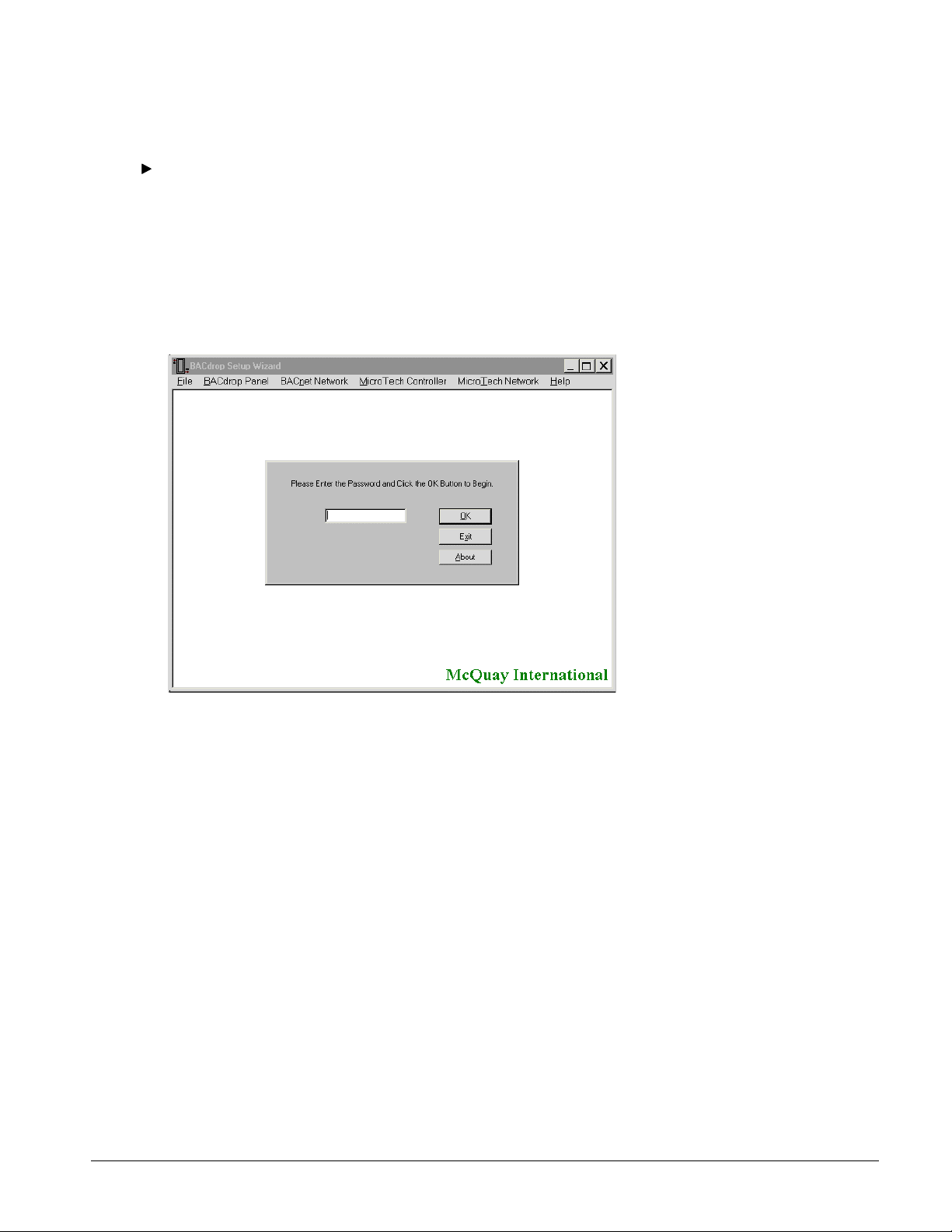
To start the BACdrop Setup Wizard
1. On the Start menu, point to Programs, BACdrop Setup Wizard, and then choose the BACdrop Setup Wizard
program.
2. Type the password in the box.
The password is “BACdrop!” (case sensitive).
3. Click OK or press Enter.
The Main screen appears.
BACdrop Setup Wizard, Main Sc reen
Working With the BACdrop Gateway
This section describes the BACdrop Setup Wizard tools that allow you to interact with the BACdrop gateway by
means of a serial cable connection. With these tools you can gather information about the MicroTech network
configuration, set up or change the BACdrop configuration file, and download program files to the BACdrop
gateway. You can also back up and restore BACdrop configuration files.
All of these tools can be found under the BACdrop Panel menu:
System Information
Configure:
Modify Controller List
Configure:
Change Network
Numbers
Download
MicroTech BACdrop Setup Wizard Online User’s Guide
Displays a list of the MicroTech controllers connected to the
BACdrop gateway. This command also displays the BACnet network
number and the MicroTech network number.
Displays a list of the MicroTech controllers and the address of each. It
also displays the Device instance number and the location of the
controller. You can edit the controller list with this tool.
Allows you to change the network number of either the BACnet
network or t he MicroTech network.
Allows you to download software into the BACdrop gateway.
Page
3
Page 4
Advanced Options:
Write Configuration
to a File
Saves a BACdrop configuration file to the PC’s hard disk or a floppy
disk.
Advanced Options:
Read Configuration
Reads and restores a BACdrop configuration file that was previously
saved to disk.
from a File
Advanced Options:
Change Timing
Parameters
Allows you to change the amount of time the BACdrop gateway waits
for responses to MicroTech network requests before timing out. These
parameters should only be changed by advanced users because
improper values can cause network problems.
To use a tool on the BACdrop Panel menu
• On the BACdrop Panel menu, choose one of the above tools.
The tool’s wizard starts and leads you through the setup. You will be asked to verify cable connections and
the COM port to be used. See below for more information on each tool.
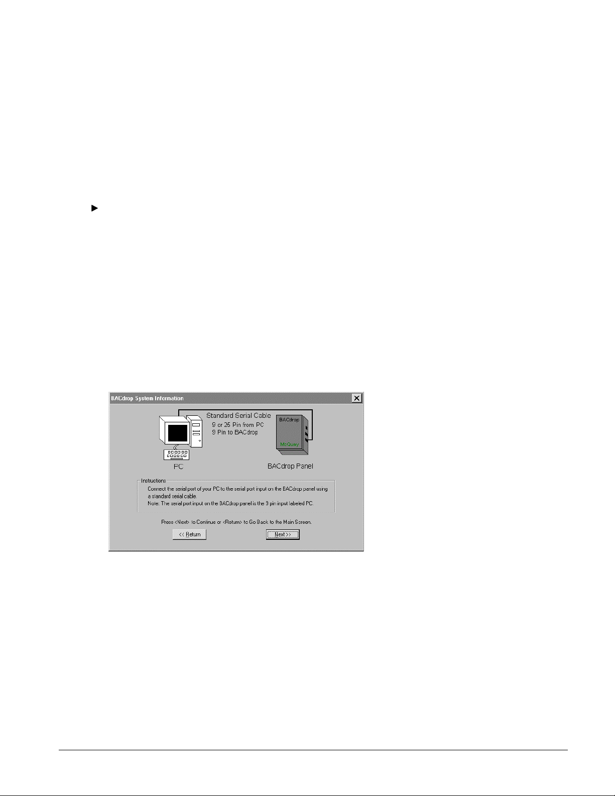
PC Hardware and Cabling Configurations
This set of tools requires a standard serial cable (not a null-modem serial cable), which is connected between the
PC serial port and the BACdrop gateway’s “PC” port. The connector on the BACdrop gateway is a female DB9.
You should know the COM port that is assigned to the PC’s serial port. The wizard will prompt for this
information.
The first screen of each tool’s wizard is a cabling diagram that helps you set up or verify cable connections. An
example is shown below.
Typical Cabling Configuration Screen for BACdrop Panel Tools
MicroTech BACdrop Setup Wizard Online User’s Guide
Page
4
Page 5
System Information Tool
The System Information tool displays basic information about the BACdrop gateway and its network
configurat i on. Some of the information may be useful to you, and some of it may b e useful to the BAS system
integration technicians. You can view the information, but you cannot change it with this tool.
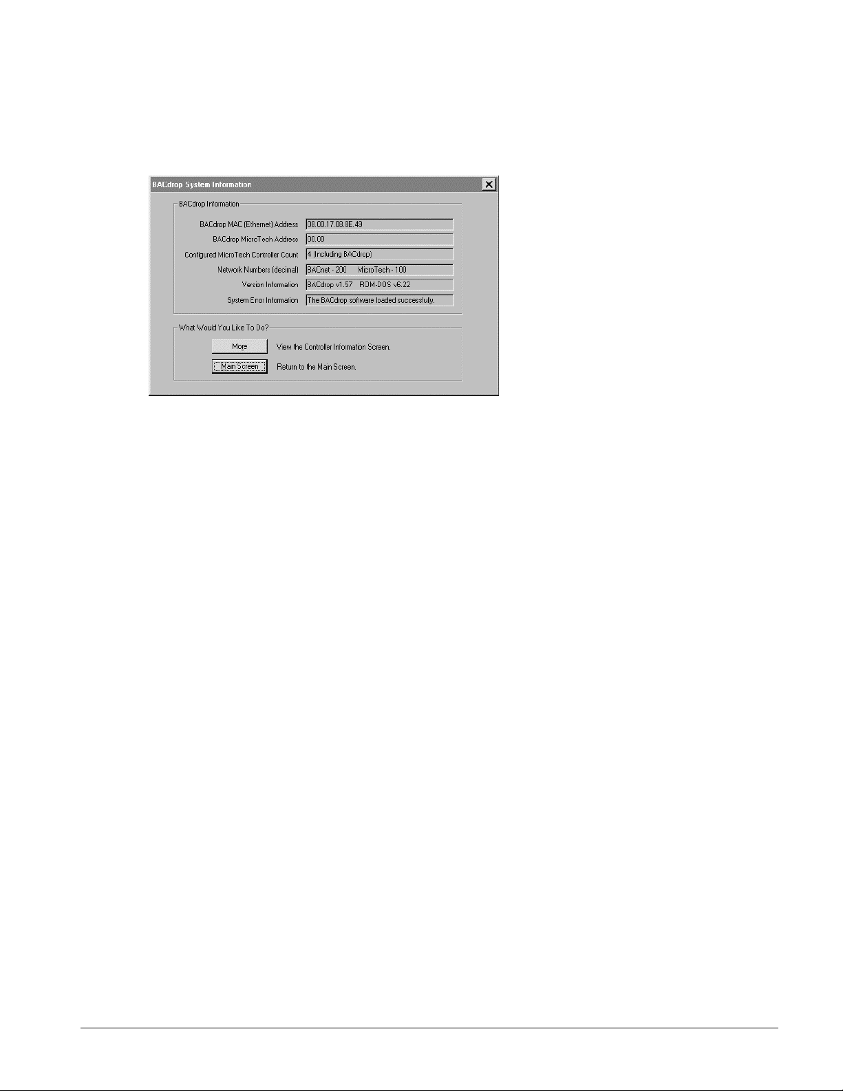
System Information Tool, BACdrop Screen
Following are brief descriptions of each information field:
BACdrop MAC
(Ethernet) Address
BACdrop MicroTech
Address
Configured
MicroTech
Controller Count
Network Numbers
(decimal)
Version Information
System Error
Information
The address of the BACdrop gateway on the Ethernet network. It is
assigned by the manufacturer of the Ethernet interface adapter and
cannot be changed.
The address of the BACdrop gateway on the MicroTech network. This
address can be changed with the BACdrop Setup Wizard’s Configure
Controller List tool. Typically, a BACdrop gateway’s MicroTech address
will be 00.00.
The total number of MicroTech controllers that have been defined in the
BACdrop configuration file. Usually this number will match the number
of MicroTech controllers on the network, but there can be exceptions; for
example, a series-100 centrifugal chiller’s display processor will exist on
the MicroTech network but will not be configured in the gateway.
BACnet numbers assigned to the MicroTech network and the BACnet
network that the BACdrop gateway is part of. The BAS system integrator
may supply these numbers. They can be changed with the BACdrop
Setup Wizard’s Configure Network Numbers tool.
The version numbers of the BACdrop gateway’s program and operating
system. If necessary, the BACdrop program can be upgraded by using the
BACdrop Setup Wizard’s Download tool.
Displays any software loading errors that have occurred. For example, if
the PMF fails to load or the Ethernet adapter driver fails to load, an error
message will appear.
Click the More button to view a list of the MicroTech controllers configured in the BACdrop gateway, or click
the Main Screen button to return to the Main screen.
If you click the More button, the BACdrop configuration file is read out of the gateway’s memory and displayed.
See figure below. Each MicroTech controller that has been entered into the configuration file is shown with its
MicroTech address, controller name or type, and Device instance number. You can view the information, but you
cannot change it with this tool.
Click the Main Screen button to close the System Information tool and return to the Main screen.
MicroTech BACdrop Setup Wizard Online User’s Guide
Page
5
Page 6
System Information Tool, BACdrop Configuration File Screen
Configure Controller List Tool
With the Configure Controller List tool, you define the MicroTech controllers that the BACdrop gateway will
translate data for. This definition includes the MicroTech network address, the standard MicroTech controller
type, and the BACnet Device object instance number. You can add, delete, or modify any of this data. As an
option, you can specify a MicroTech controller’s location, which becomes the value of the BACnet Device
object’s Location property.
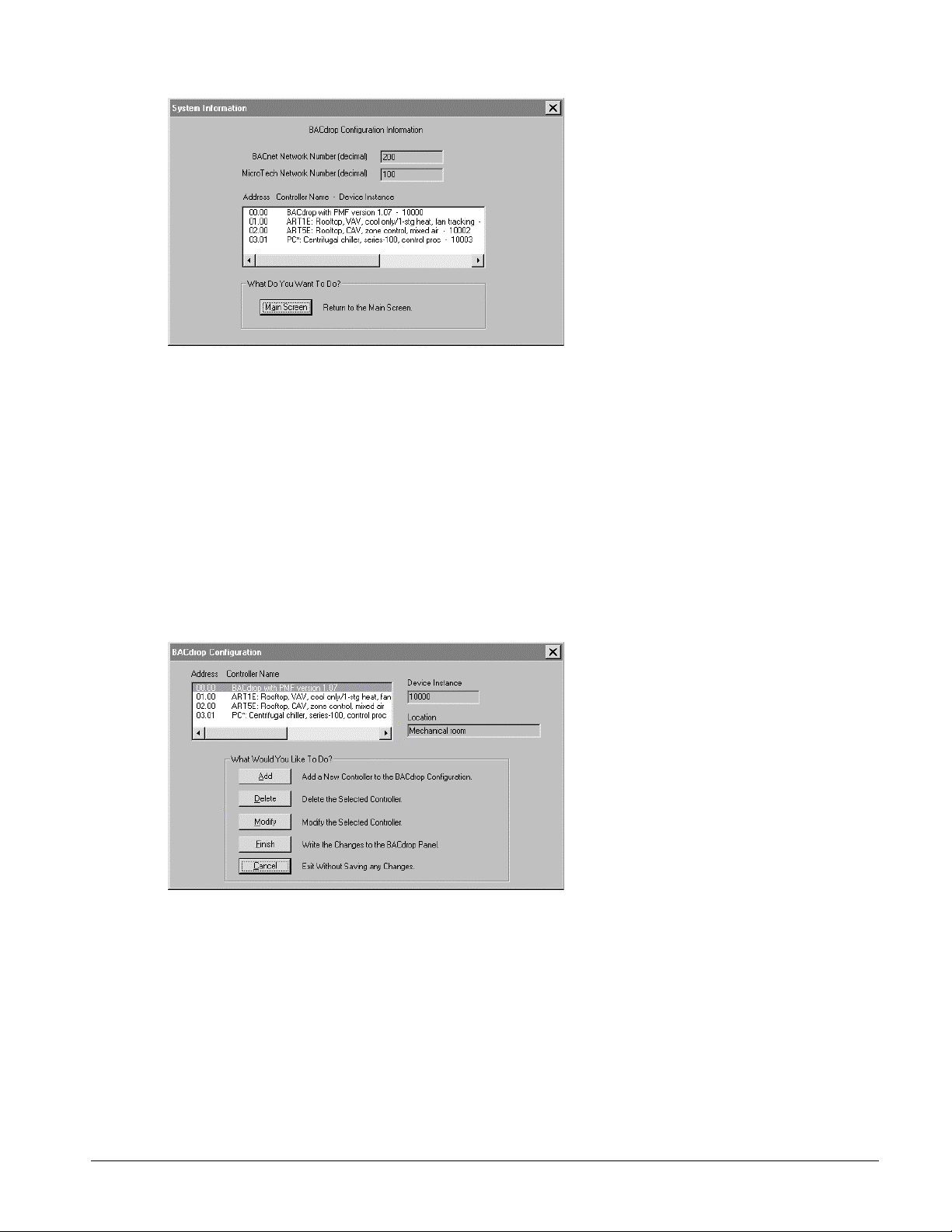
The main screen for the Configure Controller List tool is shown in the figure below. Before this screen appears,
the BACdrop Setup Wizard reads the configuration file out of the BACdrop gateway and makes a copy in the
PC’s memory. Any changes made to the configuration exist only in the PC’s volatile memory until they are saved
by clicking the Finish button. When changes are saved, they are written directly to the BACdrop gateway’s nonvolatile memory. (It is not possible to save a configuration file to the PC hard disk with this tool.)
Configure Controller List Tool, Main Screen
MicroTech BACdrop Setup Wizard Online User’s Guide
Page
6
Page 7

Adding a Controller to the Configuration File
Click the Add button to add a new controller to the configuration. When you do this, the Configure Controller
List edit screen appears. See figure below. Following are descriptions of the data-entry fields:
MicroTech
Address
Device Type
Device Instance
Location
The MicroTech network address for the controller. Each MicroTech network
address must be unique on the MicroTech network. The wizard will warn you
if you inadvertently enter a duplicate address. For more on MicroTech
addresses, see “About the Network Address” in the “Network
Commissioning” section of IM 689.
The type of the MicroTech controller, which from the perspective of the BAS
is a BACnet Device. Select the Device type from the drop-down list box. The
Device type entries come directly from the BACdrop PMF. The first part of
each entry is the prefix of the MicroTech software IDENT. The IDENT code
is listed to help you quickly identify the proper controller type.
The instance number for the BACnet Device. This number becomes part of
the Device object’s Object_Identifier property. The BAS system integrator
may provide Device instance numbers. If you know the Device instance
number, enter it over the default value. Otherwise, just use the default value
which the Setup Wizard automatically increments. (The BACdrop Setup
Wizard arbitrarily starts the numbering at 10,000.) If necessary, Device
instance numbers can be changed later. Each BACnet Device instance
number must be unique on the entire BACnet internetwork.
The physical location of the MicroTech controller or BACnet Device. The
Location information is optional. It is not needed or used by the BACdrop
gateway, but if entered, it will be visible on the BACnet network as the
Location property of the Device object.
After you have entered the new data on the Configure Controller List edit screen, click Done to accept the
changes or click Cancel to cancel the changes. When you accept the changes here, the new configuration is held
in PC memory; it is not permanently saved yet.
After leaving the edit screen, you will be returned to the Configure Controller List main screen. At this point you
can continue to add, delete, or modify controllers, or you can save the completed configuration to the BACdrop
gateway’s non-volatile memory by clicking the Finish button. If you click the Cancel button on the main screen,
all changes made to the configuration file in PC memory will be lost, and the original configuration file in the
BACdrop gateway will remain unchanged.
Configure Controller List Tool, Edit Screen
MicroTech BACdrop Setup Wizard Online User’s Guide
Page
7
Page 8

Deleting a Controller from the Configuration File
To delete a controller from the configuration, simply select it on the Configure Controller List mai n screen and
then click the Delete button. The new configuration is held in PC memory; it is not permanently saved yet.
At this point you can continue to add, delete, or modify controllers, or you can save the completed configuration
to the BACdrop gateway’s non-volatile memory by clicking the Finish button. If you click the Cancel button on
the main screen, all changes made to the configuration file in PC memory will be lost, and the original
configuration file in the BACdrop gateway will remain unchanged.
Modifying a Controller in the Configuration File
To modify a controller in the configuration, simply select it on the Configure Controller List main screen and
then click the Modify button. When you do this, the Configure Controller List edit screen appears. See figure
above. For descriptions of the data-entry fields, see “Adding a Controller to the Configuration File” above.
After you have entered the new data on the Configure Controller List edit screen, click Done to accept the
changes or click Cancel to cancel the changes. When you accept the changes here, the new configuration is held
in PC memory; it is not permanently saved yet.
After leaving the edit screen, you will be returned to the Configure Controller List main screen. At this point you
can continue to add, delete, or modify controllers, or you can save the completed configuration to the BACdrop
gateway’s non-volatile memory by clicking the Finish button. If you click the Cancel button on the main screen,
all changes made to the configuration file in PC memory will be lost, and the original configuration file in the
BACdrop gateway will remain unchanged.
Configure Network Numbers Tool
With the Configure Network Numbers tool, you define the numbers of the MicroTech network and the BACnet
network that the BACdrop gateway is part of. These BACnet numbers are used for routing messages back and
forth across the gateway. Like the controller list data, the network number data is part of the BACdrop gateway’s
configuration file. The BAS system integrator may provide the network numbers for you to enter. See figure
below.
After changing one or both network numbers, you can save the completed configuration to the BACdrop
gateway’s non-volatile memory by clicking the Finish button. If you click the Cancel button, any changes to the
network numbers will be lost, and the original configuration file in the BACdro p gateway will remain unchanged.
Configure Network Numbers Tool
Download Tool
The Download tool allows you to download updated BACdrop program files and PMF files into the BACdrop
gateway’s non-volatile memory. These files are available on McQuay International’s “McQuay OnLine” bulletin
board system. See the “BACdrop Software” section of IM 689 for more information.
The Download tool is very easy to use. After the cabling configuration and COM port selection screens, a
standard File Open dialog box appears, prompting you to select or browse for the file to be downloaded. You can
select either a BACdrop program file (e.g., BDRPv157.exe) or a PMF (e.g., PMFv107.tab). Select the drive,
MicroTech BACdrop Setup Wizard Online User’s Guide
Page
8
Page 9
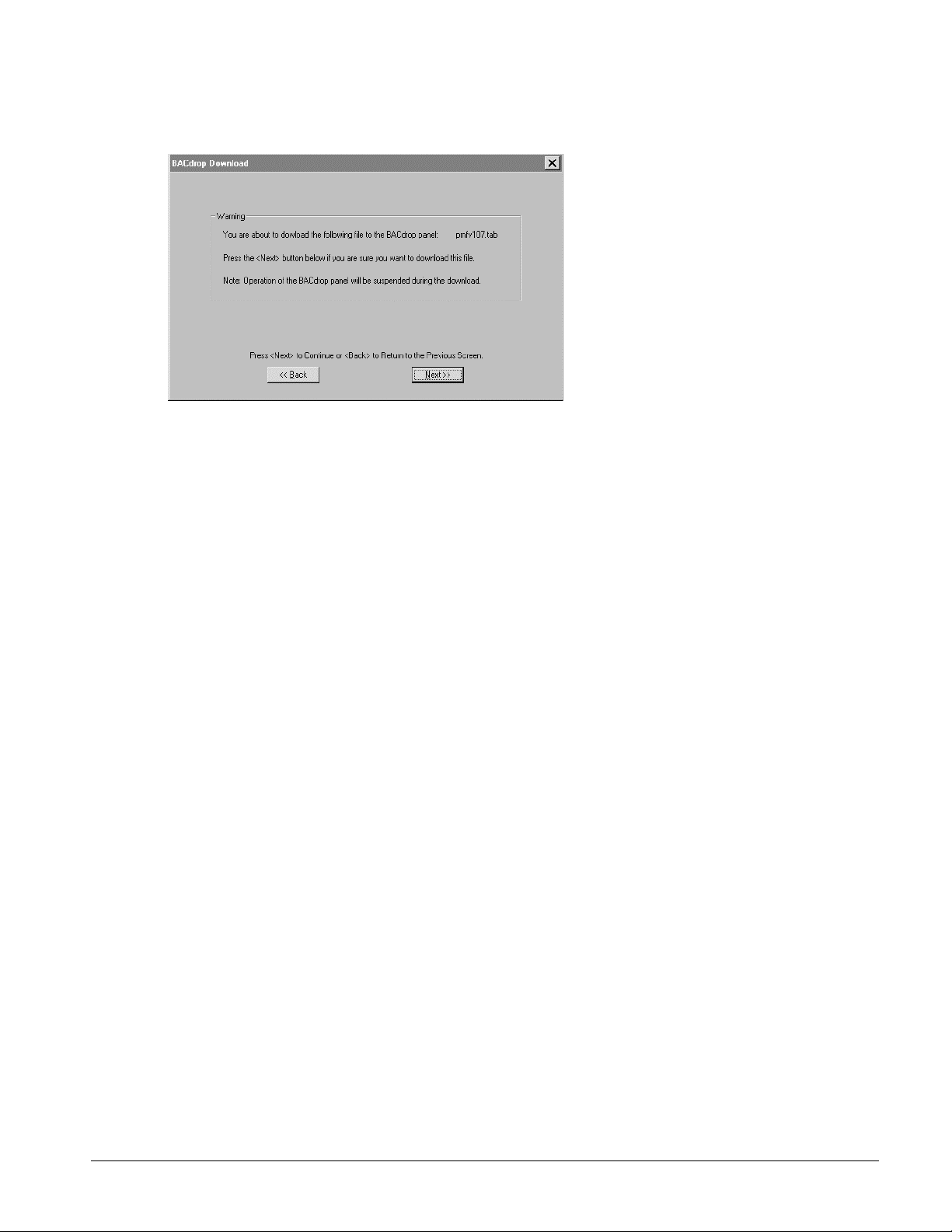
folder, and file you want to download and then click the Open button. The download confirmation screen
appears. See figure below.
Download Tool, Confirmation Screen
When you click the Next button, the file begins to download and the Downloading File dialog box appears
showing the progress of the download. If desired, you can cancel the download in progress.
Write Configuration to File (Backup) Tool
With the Write Configuration to File tool, you can save a backup copy of the BACd rop configuration file to your
PC’s hard disk or a floppy disk. If you ever need to replace the SBC or its flash memory chip, the saved
configuration file can then be quickly restored with the Read Configuration From File tool (see below).
You may also want t o use this tool if you are se t ting up two or more ver y similar BACd rop networks . A
completed configuration file can be copied to disk, restored to another BACdrop gateway, and then edited.
The wizard includes a standard File Save dialog box, which will prompt you to enter a name and location for the
configuration file to be saved. Long file names are okay, and you do not need to enter the “.cfg” file extension.
When you click the Save button in the File Save dialog box, the BACdrop Setup Wizard will read the
configuration data out of the gateway and write it to a file in the specified location.
Read Configuration From File (Restore) Tool
If you have a previously saved BACdrop configuration file on disk, you can restore it to any BACdrop gateway
with the Read Configuration From File tool. See “Write Configuration to File (Backup) Tool” above for more on
saving BACdrop configuration file s.
After restoring a configuration file, you may want to edit it with the Configure tools.
The wizard includes a standard File Open dialog box, which will prompt you to select or browse for the
configuration file to be restored. Previously saved configuration files have a “.cfg” file extension. When you clic k
the Open button in the File Open dialog box, the BACdrop Setup Wizard will read the configuration file from the
specified disk and write it to the BACdrop gateway.
Change Timing Parameters Tool (Advanced Users Only)
The Change Timing Parameters tool allows advanced users to adjust two timing limits for read and write
operations. Default values are preprogrammed and, in most applications, should not require adjustment in the
field. The timing parameters are part of the BACdrop configuration file.
Discussion of the timing parameter functions is beyond the scope of this document. Only qualified and trained
technicians should attempt to adjust them after consulting with personnel in the McQuay Controls group.
MicroTech BACdrop Setup Wizard Online User’s Guide
Page
9
Page 10

Working With the MicroTech Network Through the BACdrop Gateway
This section describes the BACdrop Setup Wizard tools that allow you to interact with the MicroTech network
from the BACnet side of the gateway. Yo u can verify communications to each MicroTech controller, and you can
read from and write to each controller by using its BACnet objects. A data packet logging tool allows advanced
users to monito r network me ssages sent between the BAS a nd the BACdrop gateway.
All of these tools can be found under the BACnet Network menu:
Network Diagnostic
Network Read/Write
Log BACnet Packets
To use a tool on the BACnet Network menu
• On the BACnet Network menu, choose one of the above tools.
The tool’s wizard starts and leads you through the setup. You will be asked to verify cable connections and
the Ethernet adapter to be used. The Network Diagnostic tool will also ask about the COM port to be used.
See below for more information on each tool.
PC Hardware and Cabling Configurations
To use this set of tools, your PC must be equipped with an Ethernet adapter that has a 10BaseT connection. Every
tool in this set uses an Ethernet connection, but the cabling configurations vary with the tool used.
For the Network Diagnostic tool, a direct Ethernet connection and a serial cable connection is required. A direct
Ethernet connection can be made with a 10BaseT crossover (or null) cable or with two standard 10BaseT cables
and a hub. See figure below.
Scans the MicroTech network for each controller defined in the
BACdrop configuration file. If a controller is found, its software
IDENT is read and displayed. If a controller is not found, an error
message is displayed. This tool is used to verify network
communicat ions during network commissioning.
Allows you to read from or write to memory locations within
MicroTech controllers by using their mapped BACnet objects.
Allows you to log BACnet data packets or all LAN packets to a file.
This tool is useful only to advanced users.
BACnet Network Diagnostic Tool, Cabling Configuration Screen
For the Network Read/Write tool, the Ethernet connection can be direct (as shown in the wizard) or over a
BACnet BAS or LAN. A direct Ethernet connection can be made with a 10BaseT crossover (or null) cable or
with two standard 10BaseT cables and a hub. A serial connection is not required. See figure below.
MicroTech BACdrop Setup Wizard Online User’s Guide
Page
10
Page 11

Network Read/Write Tool, Cabling Configuration Screen
For the Log BACnet Packets tool, the Ethernet connection must be over the BACnet BAS or LAN. This is
because the BACdrop gateway is a passive device and without a supervisory BAS to initia te requests, no
communications will occur. See figure below.
Log BACnet Packets Tool, Cabling Configuration Screen
Each tool’s wizard will present a screen that asks you to select the PC Ethernet adapter to be used. The screen
will look similar to the one shown below.
Note:
You should verify that the PC Ethernet adapter is installed and working properly before using the
BACdrop Setup Wizard. The installation and setup of a PC Ethernet adapter is beyond the scope of this
document.
Select Ethernet Adapter Scr een
MicroTech BACdrop Setup Wizard Online User’s Guide
Page
11
Page 12

BACnet Network Diagnostic Tool
The BACnet Network Diagnostic tool makes a single pass through the MicroTech network, attempting to
communicate with every controller defined in the BACdrop configuration file. It generates a report for each
controller that shows the controller’s status and, if it is communicating, its software IDENT. See figure below.
You can start another network diagnostic test by clicking the Refresh Screen button. To stop a test in progress,
click the Stop Diagnostic button.
It is worth noting that the IDENT is read from each controller’s memory; it does not come from the BACdrop
configuration file. These actual controller IDENTs can be used to verify software compatibility between the
MicroTech controllers and the BACdrop PMF. T he importance of software compatibility is discussed in the BDIP
documents and in the “BACdrop Software” section of IM 689.
The BACnet Network Diagnostic tool is very valuable during network commissioning because it can prove good
communications throughout the entire system supplied by McQuay International, from the “Ethernet” port on the
BACdrop gateway to the last MicroTech controller at the end of the daisy chain. If a BAS cannot communicate
with one or more MicroTech controllers but the BACnet Network Diagnostic tool can, the problem is almost
certainly on the BAS side of the gateway.
BACnet Network Diagnostic Tool
Network Read/Write Tool
The Network Read/Write tool allows you to read from or write to a MicroTech controller in the same manner that
a BACnet BAS would; that is, by using BACnet objects. When you read or write using BACnet objects, the
BACdrop gateway translates the requests and sends them to the specified MicroTech controllers. This tool can
thus be used to test the BACdrop gateway’s point mapping functions. It can also be used to verify
communications to a particular controller. See figure below.
When you use the Network Read/Write tool, you need at least two documents: (1) a prepared address schedule
that lists each MicroTech controller next to its MicroTech network address and (2) the BDIP for each controller
type to be read from or written to. The BDIP documents list all BACnet objects in each MicroTech controller
type, including engineering units and the meanings of enumerated object codes (e.g., 1 means “Auto”).
For example, suppose that you want to read the mixed air temperature in the self-contained air conditioning unit
on the 5th floor. The address schedule might tell you this unit is at address 05.00, and BDIP document BD 08-6
would tell you that the mixed air temperature is Analog Input object 7.
You must also know the MicroTech network number to use the Network Read/Write tool. You can find the
MicroTech network number by using the System Information tool.
MicroTech BACdrop Setup Wizard Online User’s Guide
Page
12
Page 13

Network Read/Write Tool
Reading from Objects
When you select the Read function at the top of the screen, you can read either the Present_Value property or the
Object_Name property from any BACnet object mapped to any configured MicroTech controller. After entering
all required information, click the Send button and the Setup Wizard will attempt to gather the data. If successful,
a message box that shows the requested information will appear. If not, the resultant message box will show
“unknown object.”
Writing to Objects
When you select the Write function at the top of the screen, you can write the Present_Value property to any
BACnet Analog Output or Binary Output object mapped to any configured MicroTech controller. After entering
all required information, click the Send button and the Setup Wizard will attempt to write the data. If successful,
a message box that says “The write was successful” will appear. If not, the resultant message box will show
“unknown object.”
The write function is somewhat forgiving in that it will automatically round values that have unsupported
resolution and limit values that are outside the object’s valid range. For example, if an Analog Output object has a
resolution of 1°F and a valid range of 40 to 80°F, an entered value of 61.1°F will be written as 61°F and an
entered value of 81°F will be written as 80°F.
CAUTION
!
Application knowledge required. Can cause equipment damage.
Extreme care should be taken when writing values to MicroTech controllers because unit operation can be
adversely affected. Though unlikely, equipment damage is possible if an unreasonable value or combination
of values is written to a controller. In most cases, MicroTech software has the capability to reject out-of-range
values, but even valid values can cause problems in certain situations. You must thoroughly understand the
MicroTech control application before writing any value to a MicroTech controller.
Working With MicroTech Controllers
This section describes the BACdrop Setup Wizard’s MicroTech Controller Configure tool, which allows you to
work with individual MicroTech controllers by means of a direct connection. With this tool you can gather
information about a MicroTech controller’s port speeds, port configurations, checksums, and software IDENT. If
necessary, you can also use it to change port speeds and port configurations.
To use the MicroTech Controller Configure tool
• On the MicroTech Controller menu, choose the Configure tool.
The tool’s wizard starts and leads you through the setup. You will be asked to verify cable connections and
the COM port to be used. See below for more information.
MicroTech BACdrop Setup Wizard Online User’s Guide
Page
13
Page 14

PC Hardware and Cabling Configurations
This tool requires a MicroTech PC communications cable, which is connected between the PC serial port and the
MicroTech controller’s A port (see note below). This special cable is available in a kit from McQuay
International. The part number for the DB9-style cable kit is 057186802. The kit includes adapters for the various
MicroTech controller port styles.
You should know the COM port that is assigned to the PC’s serial port. The wizard will prompt for this
information.
The first screen of the tool’s wizard is a cabling diagram that helps you set up or verify the cable connection. See
figure below.
MicroTech Controller Configure Tool, Cabling Configuration Screen
Note:
If you cannot communicate with a MicroTech controller through its A port, try the B port after first
changing the hex switch setting to FF and cycling power. The special FF hex switch setting temporarily forces the
port configuration of port B to TTY at 9600 baud. (It also forces the port configuration of port A to TTY, but at
only 1200 baud.)
MicroTech Controller Configure Tool
The basic information collected by the MicroTech Controller Configure tool can be used to troubleshoot
communications problems that may occur with specific MicroTech controllers. For example, if all but one unit
ventilator is communicating on the network, you could use this tool to check the non-communicating controller’s
port configuration (e.g., it might be set up as level 3 instead of level 2). See figure below.
MicroTech Controller Configure Tool, Information Screen
MicroTech BACdrop Setup Wizard Online User’s Guide
Page
14
Page 15

Following are brief descriptions of each information field:
MicroTech Address
The actual MicroTech network address that the controller is using. For a
level-2 controller, the first part of the address should match the hex
switch setting. For a level-3 controller, the last part of the address should
match the hex switch setting. If this is not the case, check the controller
level and/or try cycling power to the controller.
Controller Series
The style of the MicroTech controller. Different style controllers have
different memo r y map s.
Program IDENT
The program identification code for the actual MicroTech program that is
loaded in the controller.
Communication
Port Speeds
Communication
Port Configuration
The configured data transmission speeds for the two communications
ports. These configured speeds can be changed with this tool.
The port configurations of the two communications ports. The controller
level is part of the port configuration. The port configuration can be
changed with this tool. The most common level-2 configuration is shown
in the above figure.
Checksums
The checksums for the controller. The checksums must match; otherwise,
the controller’s program will not run. When you change port speeds or
configurations, the Setup Wizard will automatically adjust the Actual
checksum to match the EOS Calculated checksum.
Click the Configure button to change the MicroTech controller’s port configuration or port speeds, or click the
Main Screen button to return to the Main screen. Clicking the Refresh Screen button will cause the information to
update.
If you click the Configure button, the Setup Wizard will warn you that the tool cannot be used on certain types of
MicroTech controllers. Those controllers have special programming and changes to their port configurations can
be made only from their keypad/displays. If the controller you are connected to is not one of those listed, proceed
to the edit screen. See figure below. If the checksums do not match, the tool will not allow you to proceed to the
edit screen. In this instance, MicroTech Monitor software should be used instead.
The edit screen allows you to select new settings for the port speeds and por t configuration. After making any
changes, click the Next button to write them to the MicroTech controller. The setup Wizard will automatically
calculate and adjust the Actual checksum to match the EOS Calculated checksum.
MicroTech Controller Configur e Tool, Edit Screen
MicroTech BACdrop Setup Wizard Online User’s Guide
Page
15
Page 16
Working With the MicroTech Network Through an RS-232 to RS-485 Converter
This section describes the BACdrop Setup Wizard’s MicroTech Network Diagnostic tool, which allows you to
verify communications on the MicroTech network from the MicroTech side of the gateway. In this network
diagnostic test, the BACdrop gateway is bypassed. The level-1 controller (e.g., BACdrop or CSC) is temporarily
disconnected, and the PC and an RS-232 to RS-485 converter take its place.
To use the MicroTech Network Diagnostic tool
1. Disconnect the level-1 controller from the MicroTech network.
If the BACdrop gateway is the level-1 controller and it is in the middle of the daisy chain, make sure the
trunk remains continuo us after disconnecting it.
If the level-1 controller is a MicroTech supervisory controller (CSC, RMS, RMC, LLLB), disconnect it by
unplugging its B port AM P connector.
2. On the MicroTech Network menu, choose the Network Diagnostic tool.
The tool’s wizard starts and leads you through the setup. You will be asked to verify cable connections and
the COM port to be used. The Network Diagnostic tool will also ask about the number of level-2 controllers
on the network. See below for more information.
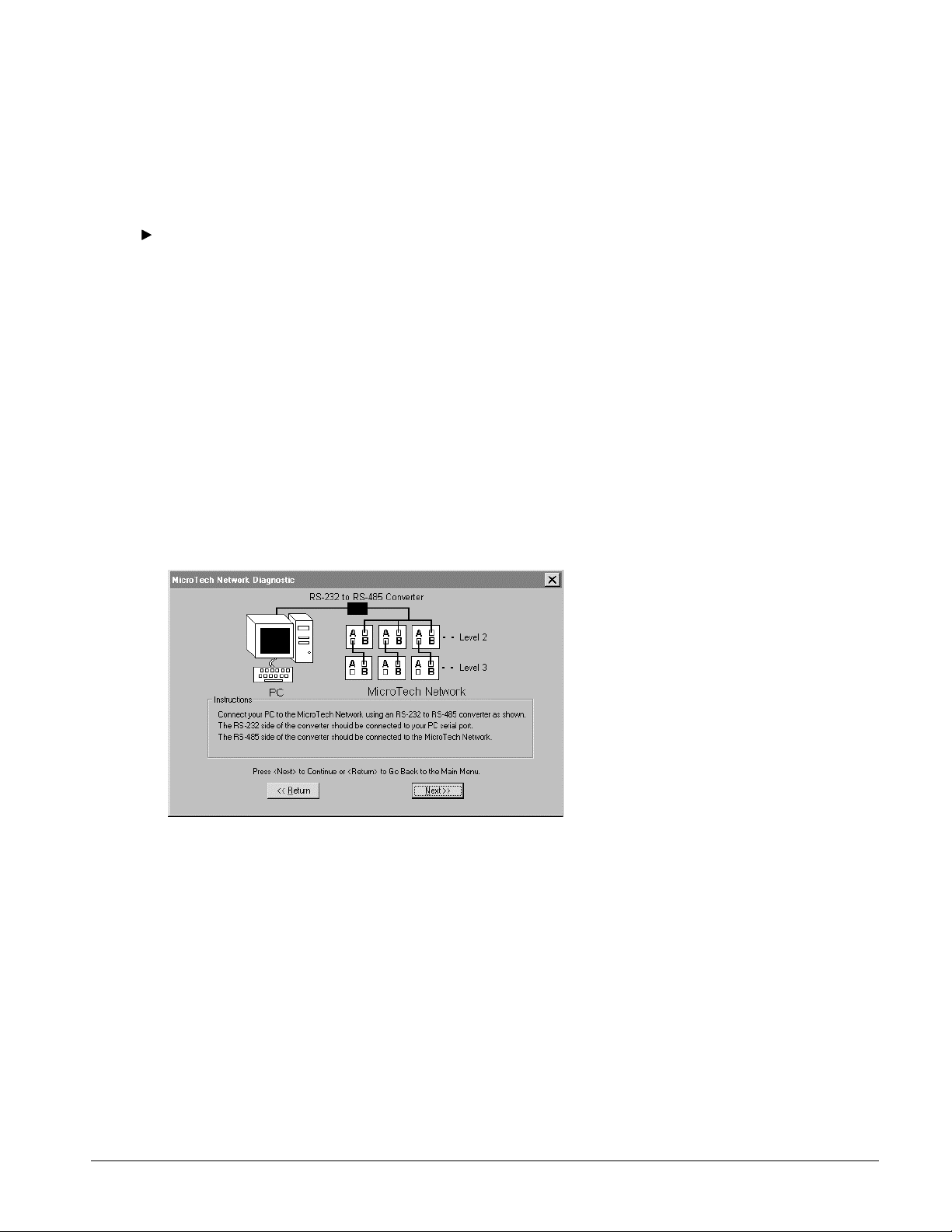
PC Hardware and Cabling Configurations
This tool requires an RS-232 to RS-485 converter and power supply (e.g., B&B Electronics models 485PTBR
and 485PS2). The RS-485 end taps into the MicroTech network at any location on the level-2 trunk, and the
RS-232 end connects to your PC’s serial port with a standard serial cable. See figure below.
MicroTech Network Diagnostic Tool, Cabling Configuration Screen
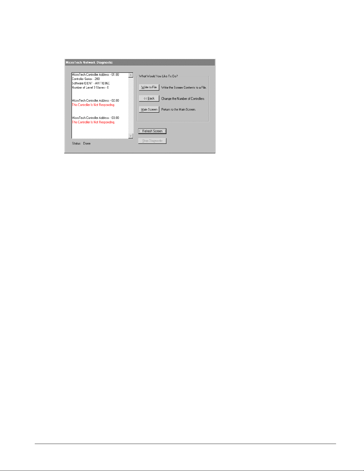
MicroTech Network Diagnostic Tool
The MicroTech Network Diagnostic tool makes a single pass through the MicroTech network, attempting to
communicate with each level-2 controller on the network, up to the number entered on the wizard screen. Any
level-3 controllers associated with a level-2 controller are also scanned. If a controller is found, its software
IDENT is read and displayed. If a controller is not found, an error message is displayed. The tool generates a
report for each controller that shows the controller’s status and, if it is communicating, its software IDENT. See
figure below.
You can start another network diagnostic test by clicking the Refresh Screen button. To stop a test in progress,
click the Stop Diagnostic button. You can also save the test results to a text file by clicking the Write to File
button.
It is worth noting that the IDENT is read from each controller’s memory. These actual controller IDENTs can be
used to verify software compatibility between the MicroTech controllers and the BACdrop PMF. The importance
of software compatibility is discussed in the BDIP documents and in the “BACdrop Software” section of IM 689.
MicroTech BACdrop Setup Wizard Online User’s Guide
Page
16
Page 17
The MicroTech Network Diagnostic tool is not capable of communicating with a level-1 MicroTech controller,
and it is not capable of communicating with a BACdrop gateway regardless of its level.
MicroTech Network Diagnostic Tool
MicroTech BACdrop Setup Wizard Online User’s Guide
Page
17
 Loading...