

Page 1

Catalog UV1620
AAF-HermanNelson
Classroom Unit Ventilators
Models AZQ, AZR, AZU Self-Contained Floor Units with R-410A
Refrigerant
C
Page 2

Contents
Introduction . . . . . . . . . . . . . . . . . . . . . . . . . . . . . . . 3
Nomenclature. . . . . . . . . . . . . . . . . . . . . . . . . . . . . . . . . . . . . . 3
AAF-HermanNelson Classroom Unit Ventilators . . . . . . . . . . . 4
The Model AZ Floor Unit . . . . . . . . . . . . . . . . . . . . . . . . . . . . . 5
Features & Benefits. . . . . . . . . . . . . . . . . . . . . . . . . 6
GentleFlo Delivery . . . . . . . . . . . . . . . . . . . . . . . . . . . . . . . . . . 6
The Right Amount of Fresh Air and Cooling. . . . . . . . . . . . . . . 7
Precise Temperature and Dehumidification Control. . . . . . . . . 7
Low Installation Costs . . . . . . . . . . . . . . . . . . . . . . . . . . . . . . . 8
Easy To Maintain . . . . . . . . . . . . . . . . . . . . . . . . . . . . . . . . . . 10
Built To Last . . . . . . . . . . . . . . . . . . . . . . . . . . . . . . . . . . . . . . 12
MicroTech II Controls . . . . . . . . . . . . . . . . . . . . . . 13
MicroTech II Controls For Superior Performance, Easy Integra-
tion . . . . . . . . . . . . . . . . . . . . . . . . . . . . . . . . . . . . . . . . . . . . . 13
Control Modes and Functions . . . . . . . . . . . . . . . . . . . . . . . . 14
System Components . . . . . . . . . . . . . . . . . . . . . . . . . . . . . . . 18
Accessories . . . . . . . . . . . . . . . . . . . . . . . . . . . . . . 24
Wall Louvers & Grilles . . . . . . . . . . . . . . . . . . . . . . . . . . . . . . 24
VentiMatic™ Shutter Room Exhaust Ventilation . . . . . . . . . . 25
Storage Cabinets, Sink & Bubbler . . . . . . . . . . . . . . . . . . . . . 26
End Panels. . . . . . . . . . . . . . . . . . . . . . . . . . . . . . . . . . . . . . . 26
Application Considerations . . . . . . . . . . . . . . . . . 27
Why Classrooms Overheat . . . . . . . . . . . . . . . . . . . . . . . . . . 27
Meeting IBC Seismic Requirements. . . . . . . . . . . . . . . . . . . . 31
Face & Bypass Temperature Control. . . . . . . . . . . . . . . . . . . 32
Modulating Valve Temperature Control . . . . . . . . . . . . . . . . . 34
Wall Sleeve Arrangements. . . . . . . . . . . . . . . . . . . . . . . . . . . 40
Unit Selection. . . . . . . . . . . . . . . . . . . . . . . . . . . . . 42
Quick Selection Procedure . . . . . . . . . . . . . . . . . . . . . . . . . . 42
Selection Procedure . . . . . . . . . . . . . . . . . . . . . . . . . . . . . . . 43
Hot Water Heating Selection. . . . . . . . . . . . . . . . . . . . . . . . . 45
Steam Heating Selection . . . . . . . . . . . . . . . . . . . . . . . . . . . 46
Engineering Data . . . . . . . . . . . . . . . . . . . . . . . . . . . . . . . . . 46
Valve Selection. . . . . . . . . . . . . . . . . . . . . . . . . . . . 50
Face and Bypass End-Of-Cycle Valve Sizing & Piping . . . . 50
Modulating Valve Sizing & Piping. . . . . . . . . . . . . . . . . . . . . 51
Steam Valve Sizing & Piping . . . . . . . . . . . . . . . . . . . . . . . . 52
Details & Dimensions . . . . . . . . . . . . . . . . . . . . . . 54
Coil Connections. . . . . . . . . . . . . . . . . . . . . . . . . . . . . . . . . . 54
Model AZ Self Contained Unit Dimensions, 024. . . . . . . . . . 57
Model AZ Self Contained Unit Dimensions, 036. . . . . . . . . . 58
Model AZ Self Contained Unit Dimensions, 044, 054. . . . . . 59
End Panels . . . . . . . . . . . . . . . . . . . . . . . . . . . . . . . . . . . . . . 60
Valve Dimensions. . . . . . . . . . . . . . . . . . . . . . . . . . . . . . . . . 61
Wall Intake Louvers & Grilles . . . . . . . . . . . . . . . . . . . . . . . . 62
VentiMatic Shutter Assembly . . . . . . . . . . . . . . . . . . . . . . . . 63
Sink & Bubbler Cabinet. . . . . . . . . . . . . . . . . . . . . . . . . . . . . 64
Filler Sections & Utility Compartment . . . . . . . . . . . . . . . . . . 65
Shelf Storage Cabinets. . . . . . . . . . . . . . . . . . . . . . . . . . . . . 66
Wiring Diagrams . . . . . . . . . . . . . . . . . . . . . . . . . . 68
Typical MicroTech II Wiring Diagrams . . . . . . . . . . . . . . . . . 68
Guide Specifications . . . . . . . . . . . . . . . . . . . . . . . 71
AAF-HermanNelson Unit Ventilator Model AZ Guide Specifica-
tions . . . . . . . . . . . . . . . . . . . . . . . . . . . . . . . . . . . . . . . . . . . 71
C
McQuay is a registered trademark and MicroTech II, Digital Ready, GentleFlo, ServiceTools,
Microsoft is a registered trademark and Windows is a trademark of Microsoft Corporation.
and Protocol Selectability are trademarks of McQuay International.
Copyright © 2010 McQuay International. All rights reserved throughout the world.
Page 3

Introduction
A
A
A
t
Introduction
Nomenclature
UC0246AZU G 65 B1Z
Product Category
U = Unit Ventilator
Product Identifier
ZQ = SC - a/c Face & Bypass
Heating, Ultra Quiet
ZU = SC - a/c Valve Heating,
Ultra Quiet
ZR = SC - a/c Valve Reheat
Design Series
6 = F-Series
Nominal Capacity
024 = 24000 BTUH
036 = 36000 BTUH
044 = 44000 BTUH
054 = 54000 BTUH
Voltage
C = 208V, 60Hz, 1Ø
D = 208V, 60Hz, 3Ø
G = 230V, 60Hz, 1Ø
H = 230V, 60Hz, 3Ø
K = 460V, 60Hz, 3Ø
Cooling Coil Options
G = Direct Expansion
H = Direct Expansion with Refrigerant Relief Valve
Heating Options
00 = None
12 = Low Electric Heat, 3-Element
13 = High Electric Heat, 6-Element
65 = 1 Row Hot Water
66 = 2 Row Hot Water
68 = Steam, Low Capacity
69 = Steam, High Capacity
Hand Orientation
Z = Not Applicable
Control Options
B1 = Basic Stand-Alone w/o TC
B2 = Basic Stand-Alone Master w/o TC
B3 = Basic Stand-Alone Slave w/o TC
B4 = Basic BACnet MS/TP w/o TC
B5 = Basic LonMark SCC w/o TC
B6 = Basic Metasys N2 Open w/o TC
B7 = Basic Stand-Alone w/ TC
B8 = Basic Stand-Alone Master w/ TC
B9 = Basic Stand-Alone w/o TC w/CO2
BA = Basic Stand-Alone Master w/o TC w/CO2
BB = Basic Stand-Alone Slave w/o TC w/CO2
BC = Basic BACnet MS/TP w/o TC w/CO2
BD = Basic LonMark SCC w/o TC w/CO2
BE = Basic Metasys N2 Open w/o TC w/CO2
BF = Basic Stand-Alone w/ TC w/CO2
BG = Basic Stand-Alone Master w/ TC w/CO2
AL 22 G BC1
Product Style
1 = Product Style 1
SKU Type
B = Std. Delivery
C = Ext. Delivery
Color
I = Antique Ivory
W = Off White
B = Putty Beige
G = Soft Gray
Power Connection
G = Box with Switch
Return Air/Outdoor Air
22 = Return Air Front,
Outdoor Air Rear
Discharge
AL = 16 5/8" Top Bar
Control Options (continued)
E1 = Expanded Stand-Alone w/o TC
E2 = Expanded Stand-Alone Master w/o TC
E3 = Expanded Stand-Alone Slave w/o TC
E4 = Expanded BACnet MS/TP w/o TC
E5 = Expanded LonMark SCC w/o TC
E6 = Expanded Metasys N2 Open w/o TC
E7 = Expanded Stand-Alone w/ TC
E8 = Expanded Stand-Alone Master w/ TC
E9 = Expanded Stand-Alone w/o TC w/CO2
EA = Expanded Stand-Alone Master w/o TC w/CO2
EB = Expanded Stand-Alone Slave w/o TC w/CO2
EC = Expanded BACnet MS/TP w/o TC w/CO2
ED = Expanded LonMark SCC w/o TC w/CO2
EE = Expanded Metasys N2 Open w/o TC w/CO2
EF = Expanded Stand-Alone w/ TC w/CO2
EG = Expanded Stand-Alone Master w/ TC w/CO2
L1 = Leading Stand-Alone w/o TC
L2 = Leading Stand-Alone Master w/o TC
L3 = Leading Stand-Alone Slave w/o TC
L4 = Leading BACnet MS/TP w/o TC
L5 = Leading LonMark SCC w/o TC
L6 = Leading Metasys N2 Open w/o TC
L7 = Leading Stand-Alone w/ TC
L8 = Leading Stand-Alone Master w/ TC
L9 = Leading Stand-Alone w/o TC w/CO2
LA = Leading Stand-Alone Master w/o TC w/CO2
LB = Leading Stand-Alone Slave w/o TC w/CO2
LC = Leading BACnet MS/TP w/o TC w/CO2
LD = Leading LonMark SCC w/o TC w/CO2
LE = Leading Metasys N2 Open w/o TC w/CO2
LF = Leading Stand-Alone w/ TC w/CO2
LG = Leading Stand-Alone Master w/ TC w/CO2
44 = Electromech w/2-Pos Damper for Remote T'Sta
45 = Electromech w/2-Pos Damper w/Unit Mtd. ACO
46 = Electromech w/2-Pos Damper w/Unit Mtd. MCO
Grille Unit
AAF-HermanNelson Model AZ Unit Ventilators 3
Page 4

Introduction
AAF-HermanNelson Classroom Unit Ventilators
For more than 89 years, schools have relied on
AAF-HermanNelson unit ventilators to keep classrooms
comfortable. Students learn more readily in a quiet, wellventilated environment. That’s why Herman Nelson
invented the unit ventilator and why we remain
committed to meeting the changing requirements of
schools with the highest quality products available.
We realize that keeping expenditures down is a high
iority for school administrators and school boards.
r
p
AAF-HermanNelson unit ventilators are inexpensive to
install and operate, and they are designed and built to
provide decades of trouble-free service.
Built To Last
Our proven institutional design can withstand the rigors
of the classroom environment. It features an extra-sturdy
chassis and double-wall damper on the inside; scuffresistant finishes and tamper prevention features on the
outside. In fact, many units installed over 30 years ago
continue to provide quiet, reliable classroom comfort.
Heavy Duty Frame Construction
AAF-HermanNelson’s exclusive, unitized welded frame
is far superior to the fastener-type construction used by
other manufacturers. Loosened fasteners can cause
vibration, rattles and sagging panels.
Other design features that promote trouble-free
per
ation and long life include:
o
• A corrosion-resistant, galvanized-steel frame.
• Extra-strength, steel-bar disc
• Heavy-gauge-metal cabinet access panels and doors.
• An extra-str
ength pipe tunnel that stiffens the structure
while adding aerodynamic air flow within the unit.
• Hidden reinforcement that provides additional built-in
ort for the top section as well as better support for
supp
the fan deck assembly.
harge grille.
igid exterior that is strong enough to support
• A r
main
tenance personnel without fear of damaging the
unit.
Rugged Exterior Finish
The superior finish of the unit ventilator cabinet fosters
long-lasting beauty as well as resistance to abuse and
corrosion. We apply the very highest standards at every
step of the finishing process to provide lasting quality:
• Exter
ior cabinet panels are fabricated from high-
qua
lity, furniture grade steel with no sharp edges.
• A specially formulated, environmentally friendly,
ermosetting urethane powder is applied
th
electrostatically to the exterior panels. This film is
oven-cured to provide correct chemical cross-linking
and to obtain maximum scuff- and mar-resistance.
he top of the unit is finished with a textured, non-glare
• T
and
scuff-resistant, charcoal bronze electrost atic pa int.
End and front panels are available in a pleasing array
of architectural colors.
he Oxford brown steel kickplate is coated and baked
• T
with a
thermosetting urethane powder paint to blend
with floor moldings and provide years of trouble-free
service.
h unit is painstakingly inspected before
• Eac
then encapsulated in a clear plastic bag, surrounded
by an extra-heavy-duty cardboard box and secured to
a skid to help provide damage-free shipment.
MicroTech II Control For Superior Performance, Easy Integration
AAF-HermanNelson unit ventilators can be equipped
with MicroTech II™ unit controllers for superior
performance. Factory integrated and tested controller,
sensor, actuator and unit options promote quick, reliable
start-up and minimize costly field commissioning. Our
Protocol Selectability feature provides easy, low-cost
integration into most building automation systems. Select
BACnet
communications to communicate control and monitoring
information to your BAS, without the need for costly
gateways. Unit controllers are L
the optional L
®
, LonTalk® or Metasys® N2 Open
ONWORKS
®
communication module.
ONMARK
®
certified with
boxing,
4 McQuay Catalog 1620
Page 5
Introduction
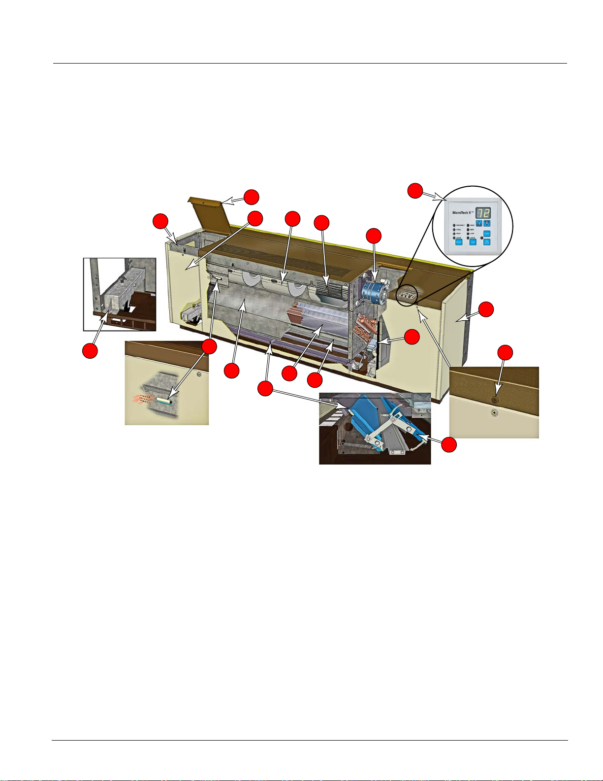
The Model AZ Floor Unit
Our Model AZ is a vertical, floor-standing unit that utilizes
refrigerant for cooling, and hot water, steam or electric
heat for heating. The Model AZ also can be supplied as a
cooling/ventilating unit only.
11
13
1
10
12
2
4
8
6
The Model AZ is just right for new construction and for
etrofit applications. Older buildings with baseboard
r
radiant heat or other hydronic heating systems can be
easily adapted to work efficiently with Model AZ units.
The major features of this model are shown below and
described in more detail on the following pages.
7
3
5
9
16
17
15
1 Welded One-Piece Chassis offers
superior strength, durability, and
vibration reduction.
2 Unique Draw-Thru Design provides
uniform air distribution across the coil
for even discharge air temperatures.
3 Quiet, Aerodynamic Fans utilize
GentleFlo technology for
exceptionally quiet unit operation.
4 Modular Fan Section improves
balance, alignment and simplifies
maintenance.
5
Fan Motor Located Out Of Air
Stream
and away from heating coil
reduces heat exposure to prolong life.
6 Outside Air/Return Air Damper &
Linkage Provides superior mixture of
outdoor air and room air for precise
temperature control.
7 MicroTech II Controls provide
superior comfort control and easy
integration into the building
automation system of your choice.
8 Advanced Heat Transfer Coil
design provides extra capacity.
9 Sturdy Cabinet Construction
includes hidden reinforcement, a
non-glare textured surface, and a
tough, scuff- and mar-resistant finish
to make the top sturdy enough to
support maintenance personnel.
10 Sectionalized Front Access Panels
provide easy access to unit interior.
Panels are easily removed by a
single person. Front side panels can
be removed while unit is running.
14
11 Two Hinged To p Access Doors
provide easy access to the motor,
electrical, and refrigeration
components..
12 Sampling Chamber for unit-
mounted sensor provides accurate
sensing of room temperature.
13 Optional Adjustable Caster (Left
and Right Ends).
14 Insulated Double-Wall Outdoor Air
Damper seals tightly without
twisting.
15 Full-leng t h Air Filt er is efficient and
easy to replace. All air delivered to
classroom is filtered.
16 Corrosion Proof Sloped Drain Pan.
17 Tamper Resistant Fasteners on
Access Panels
AAF-HermanNelson Model AZ Unit Ventilators 5
Page 6

Features & Benefits
Features & Benefits
GentleFlo Delivery
AAF-HermanNelson unit ventilators are engineered and
manufactured to deliver quiet, continuous comfort. We
developed our GentleFlo™ air moving syst em to
minimize operating sound levels—even as demands for
more fresh air require units to operate longer and work
harder. GentleFlo featur es include:
wheels are large, wide and rotate at a low speed
• Fan
to red
uce fan sound levels. They are impact-resistant
and carefully balanced to provide consistent
performance.
fset, aerodynamic fan wheel blades move air
• Of
ef
ficiently (Figure 1).
• Precision tolerances help reduce flow and pr es su re
turbulence, resulting
in lower sound levels.
• Fan housings incorporate the latest logarithmic-
ansion technology for smoother, quieter air flow
exp
(Figure 2).
Figure 1. GentleFlo Fan Technology
Expanded discharge air
opening
• A large, expanded discharge opening minimizes air
resistance, further lowering sound levels.
• Modular fan construction contributes to equal outlet
locities and promotes quiet operation.
ve
• Fan shafts are of ground and polish ed steel to
ize deflections and provide consistent, long-term
minim
operation.
• Fan assemblies are balanced before unit assembly,
en tested after assembly (and rebalanced if
th
necessary) to provide stable, quiet operation.
Figure 2. GentleFlo Reduces Turbulence
Minimal
Offset aerodynamic blades
Logarithmic expansion housing
Precision Tolerances
6 McQuay Catalog 1620
GentleFlo fan blade design
turbulence
Typical fan blade design
High turbulence
Page 7
Features & Benefits
The Right Amount of Fresh Air and Cooling
AAF-HermanNelson unit ventilators deliver required
amounts of fresh air to meet ventilation requirement s and
added cooling capacity to maintain consistent comfort for
students and teachers. Our Economizer Operation,
Demand Control Ventilation (DCV) and Part Load,
Variable Air options allow you to mat ch cla ssr oo m
comfort requirements even more closely, and reduce
operating costs.
at your school is
This means that you can be confiden
meeting ventilation standards for Indoor Air Quality and
that your students are receiving adequate air to be
attentive to instruction. At the same time, you are saving
money in early morning hours, between classes or after
hours when classrooms are heated and cooled but not
always fully occupied.
Economizer Operation
It is well recognized that cooling, not heating, is the main
thermal challenge in school classrooms. The typical
classroom is cooled by outdoor air over half the time,
even in cold climates. It is therefore essential that unit
ventilators efficiently deliver outdoor air when classroom
conditions call for “free” or economizer cooling.
With AAF-HermanNelson unit ventilators, you can have
tdoor air whenever it is needed. Economize r operatio n
u
o
is facilitated by the outdoor air damper, which
automatically adjusts the above-minimum outside air
position to provide free cooling when the outdoor air
temperature is appropriate (Figure 3). On unit s equippe d
with MicroTech II controls, three levels of economizer
rol are available (see See “Economizer Modes” on
t
con
page 14).
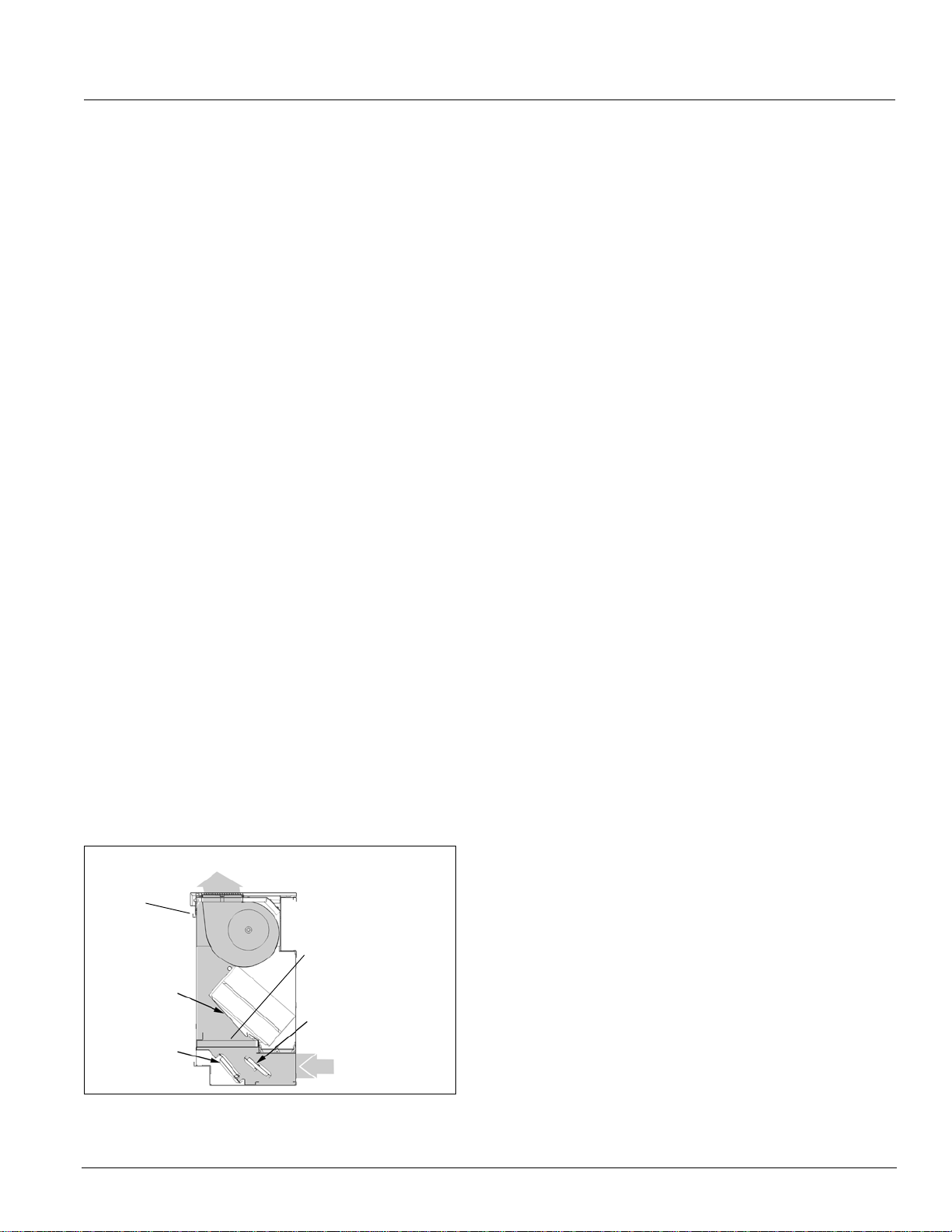
Figure 3. Full Economizer Mode
100% Outdoor Air Into Classroom
Condenser
Section
Face &
Bypass
Damper
Room Air
Damper
t th
Filter
Outdoor Air
Damper
Outdoor Air
Part-Load Variable Air Control
Part Load Variable Air control can be used in conjunction
with face and bypass damper temperature control to
automatically adjust the unit ventilator fan speed based
upon the room load and the room temperat ure. This
MicroTech II control option provides higher latent cooling
capabilities and quieter operation during non-peak load
periods by basing indoor fan speed upon room load.
Lower fan speeds in conjunction with our GentleFlo fan
technology contributes to a very quiet classroom
environment.
Room-temperature PI control loops determine the speed
e fan, wh
of th
also provides a built-in delay to prevent overshooting for
better comfort control. The outdoor air damper’s
minimum-air position is adjusted with the fan speed to
bring in a constant amount of fresh air.
ich varies according to the room load. It
Precise Temperature and Dehumidification Control
AAF-HermanNelson unit ventilators provide precise
temperature and dehumidification control to keep
students and teachers comfortable while making
maximum use of “free” outdoor-air cooling to reduce
operating costs. They utilize a draw-thru fan design that
contributes to even heat transfer and provides uniform
discharge air temperatures into the classroom.
MicroTech II active dehumidification control strategies
and 2-stage compressor operation, provide precise
control of temperature and humidity levels under both
part-load and full-load conditions.
Draw-Thru Design For Even Discharge Temperatures
The AAF-HermanNelson Draw-Thru design sets our unit
ventilators apart from most competitive models. With this
system, fans draw air through the entire heat transfer
element (Figure 4) rather than blowing it through highly
concentrated areas of the coil element. The result is
o
re uniform discharge air temperatures into the
m
classroom and more efficient unit ventilator operation.
AAF-HermanNelson Model AZ Unit Ventilators 7
Page 8

Features & Benefits
Figure 4. Draw-Thru Design Provides Even Discharge Air
Uniform Discharge Air (Shaded)
Motor
Fans
Condenser
Face & Bypass Design For Better Temperature Control
When coupled with our draw-thru design, face and
bypass damper air control offers optimal temperature
control in heating. That’s because indoor and out d oo r air
streams can be separated until it is optimal to mix them.
Figure 5. Draw-Thru Vs. Blow-Thru Design
Coil
Filter
RA/OA
Divider
Room Air
Outdoor Air
Blow-Thru Design
Face &
Bypass
Damper
Room Air
Damper
Room Air
AAF-HermanNelson
Draw-Thru Design
Coil
Outdoor
Air Damper
Outdoor Air
Active Dehumidification (Reheat)
In high-humidity applications where valve-controlled,
reheat units are used, the Active Dehumidification
Control (ADC) sequence should be considered. With the
Leading Edge Microtech II controls, an inside humiditst at
compares indoor humidity (enthalpy) with outdoor
humidity to determine the economizer position.
During excessive humidity conditions
, a humidity
sensor
directs the unit to continue cooling p ast the room setpoint
to remove moisture. Hydronic heat or electric heat is
then used to reheat the discharge air to maintain
acceptable room temperatures.
Increased Coil Freeze Protection
AAF-HermanNelson units equipped with face and
bypass damper control, provide extra protection from coil
freeze-up, because there is a constant flow of hot water
through the coil, and water that is flowing typically does
not freeze. Additionally, all AAF-HermanNelson units
feature a double-walled, insulated outdoor air damper
with airtight mohair seals to prevent unwanted coil air
from entering the unit.
Furthermore, a low-temperature freezestat is factory
inst
alled on
all units with hydronic coils. Its serpentine
capillary tube senses temperatures across the leaving air
side of the coil, allowing the unit controller to react
quickly to low-temperature conditions.
Figure 6. Freezestat
Freezestat
Capillary Tube
Low Installation Costs
Perfect For Both New & Retrofit Applications
New construction installations are easily accomplished
with AAF-HermanNelson unit ventilators because they
avoid the added cost and space required for expensive
duct work. Further savings can be realized because
piping installations use less space than duct systems.
This is important in existing buildings and also in new
construction where floor-to-floor heights can be reduced,
saving on overall building costs.
Retrofit installations are economical because new units
pically
ty
Using AAF-HermanNelson unit ventilators, central
equipment, such as chillers, can be sized smaller using
building diversity. This results in a low capital-cost
system.
Built In Flexibility
AAF-HermanNelson unit ventilators include features that
make them easy to set up and reconfigure as needed to
meet special requirements. These features include:
• Built-In Wire Race A built-in meta
fit the same space occupied by existing ones.
l wire race runs from
one end of the unit to the other to provide extra
protection for wires and protect them from unit air.
8 McQuay Catalog 1620
Page 9
Features & Benefits
Figure 7.
Condenser casters ease
installation. Optional indoor
casters can be adjusted.
Condenser Casters and Optional Unit Casters
Controls Flexibility
Multiple control options—including MicroTech II controls
with our Protocol Selectability feature—provide easy , low
cost integration of AAF-HermanNelson unit ventilators
into the building automation system of your choice (See
“MicroTech II Controls” on page 13) . You can also
operate these units individually or in a master-servant
t
rol configuration.
con
With MicroTech II controls, you can select BACnet,
alk or Metasys N2 communications to communicate
LonT
control and monitoring information to your BAS, without
need for costly gateways. Unit controllers are
the
ONMARK certified with the optional LONWORKS
L
communication module.
Then consider how AAF-HermanNelson unit ventilators,
locate
d in each classroom, take advantage of these
realities to lower operating costs:
• They provide individual classroom control and comfort.
• They can be cycled on
when the room is occupied and
cycled off when it is not.
• They bring in fresh air from directly outside the
ssroom for high indoor air quality.
cla
• During most of the school year, they use outdoor air to
ep classrooms comfortable without the expense of
ke
mechanical cooling.
MicroTech II Control Options Further Reduce Operating Costs
Many of the MicroTech III control options available with
AAF-HermanNelson unit ventilators can further reduce
operating costs. For example:
• Economizer Operation Econ
automatically adjusts the above-minimum outside air
position to provide free cooling when the outdoor air
temperature is appropriate.
• Demand Control Ventilation By usin
monitor the actual occupancy pattern in a room, the
system can allow code-specific levels of outdoor air to
be delivered when needed without costly overventilation during periods of low or intermittent
occupancy (Figure 8).
omizer operation
g CO
levels to
2
Low Operating Costs
Schools consume more than 10% of the total energy
expended in the United States for comfort heating and
cooling of buildings. As energy costs increase, educators
are placed in a difficult position: caught between rising
costs, lower budgets and the requirements to raise
educational standards.
e system exists for
Fortunately, the technology an
schools to take control of their energy expenditures wh ile
providing a comfortable environment for learning. And
that system is the AAF-HermanNelson unit ventilator.
Consider these realities of school environments:
• Most
heating energy in schools is expended to heat
un
occupied spaces. Because lights, computers and
students give off considerable heat, occupied spaces
require little supplemental heat.
• The
removal
of heat is usually required in occupied
classrooms, even when outside temperatures are
moderately cold (i.e., 35-40°F).
d th
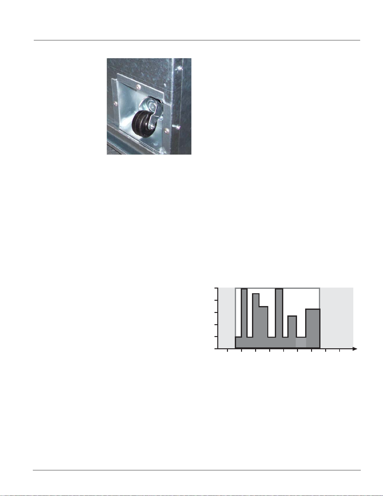
Figure 8. Energy Savings with Demand Control Ventilation
100%
Energy Savings
with DCV
Unoccupied
20%
DCV's fresh air for indoor air quality
6:00 8:00 10:00 12:00 2:00 4:00 6:00 8:00 10:00
School Hours
Cleaning
After Hours
Unoccupied
• Occupancy Mode Operation Units can be
programmed to operate only sparingly during
unoccupied periods and at night to conserve energy.
Two Stage Compressor
Air conditioning units are usually sized for worse case
conditions. During high load requirement the unit will
operate in high fan speed and high compressor capacity.
Most of the time there is not a full load on the
compressor. Operation in lower load will be at medium or
AAF-HermanNelson Model AZ Unit Ventilators 9
Page 10
Features & Benefits
low fan speeds which will be at the lower displacement
compressor stage. The two stage compressor will remain
at low speed until more cooling is required. With the twostage compressor, these units will run on lower fan
speeds most of the time improving comfort through
better humidity control and quieter operation, while
minimizing issues with over-sizing.
ors operate at
Other units utilizing single stage compres
full compressor capacity all of the time regardless of fan
speed.
s
Easy To Maintain
Fan Deck
The fan deck’s rotating element has one large, selfaligning, oilable end bearing for smoother operation.
Figure 9. Long-Life Bearings
Long Life Bearing
Even “permanently” lubricated motors are supplied with
recommended lubrication charts calling for lubrication
every seven years. Maintenance instructions of the
motor manufacturer should be followed clo sely.
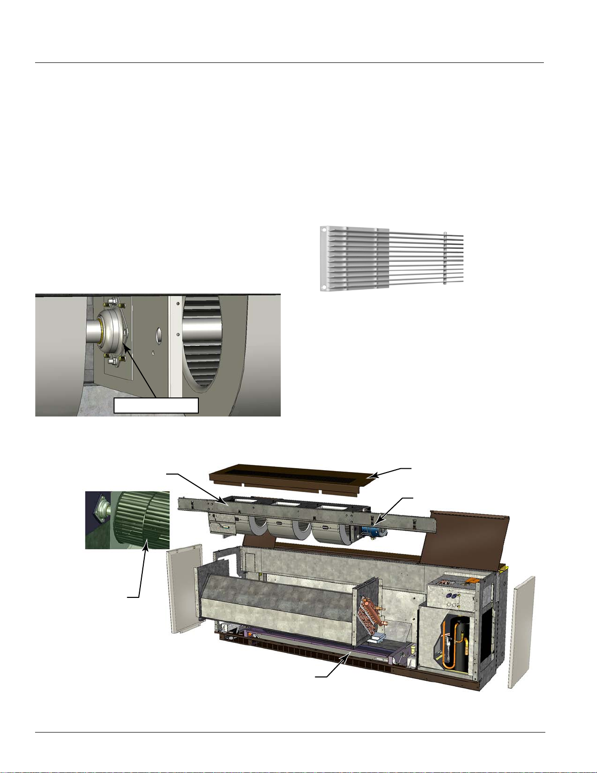
Heavy-Duty Discharge Grille
The discharge grille on the top of the unit is made from
extra-strength steel bar stock, promoting long life
(Figure 10). It can be removed to facilitate cleaning
fans and fan housings.
Figure 10. Heavy-Duty Steel Discharge Grille
of
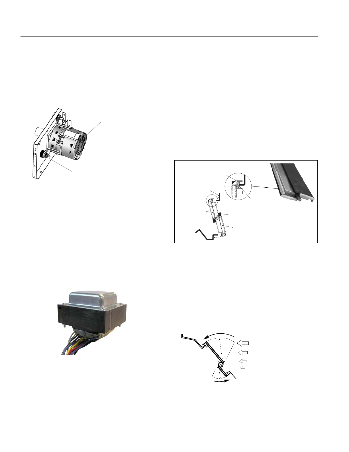
Internal Fan Deck Components
Unlike with many competitive models, the motor in
AAF-HermanNelson unit ventilators is separate from the
fan assembly and is located out of the airstream at the
end of the fan shaft—away from the hot coil—for easier
maintenance and removal. Locating the motor away from
the coil (Figure 11) has the added benefit of extending
motor life. Our direct-coupled motor and self-aligning
r mount facilitate motor change-out. The motor
to
mo
comes with a molex plug that fits all sizes and further
simplifies removal.
Figure 11. Fan Deck
Aerodynamic Fans
Modular
Fan Deck
Heavy-Duty
Discharge Grille
Motor Located
Out of Airstream
Filter
10 McQuay Catalog 1620
Page 11

Features & Benefits
Tamper-Resistant Fasteners
Front panels and top access doors are held in place by
tamper-resistant, positive-positioning fasteners. They are
quickly removed or opened with the proper tool, but deter
unauthorized access to the unit’s interior (Figure 12).
Sectionalized Access Panels And Doors
All units have three separate front panels and hinged top
access doors, sized for convenient handling by a single
person (Figure 12). The result is easy , t argeted access to
the component that needs servicing:
wo end panels provide easy access to piping,
• T
te
mperature control components and the fan switch.
Unlike units with full-length front panels, these can be
removed without disturbing the normal operation of the
unit.
ged top access doors provide easy access into the
• Hin
end c
ompartments to facilitate convenient servicing of
the motor, electrical, and refrigeration components.
• Center front panel provides easy access to the filter
d fan shaft bearing (size 048 only).
an
Filter
Three filter types are offered:
• Units come standard with a single-use filter which is
de
signed to be used once and discarded.
• Optional, permanent metal filters are available and can
removed for cleaning and reused numerous times.
be
• Renewable media filters, which consist of a heavy-
uty, painted-metal structural frame and renewable
d
media.
Figure 12. Easy Access With Tamper-Resistant Fasteners
Tamper Resistant
Fasteners
Tamper Resistant
Fasteners
Discharge
Grille
Tamper Resistant
Fasteners
Tamper Resistant
Fasteners
Removeable
Filter
AAF-HermanNelson Model AZ Unit Ventilators 11
Page 12
Features & Benefits
Built To Last
Durable, Energy Efficient Fan Motors
AAF-HermanNelson unit ventilators are equipped with
1 15/60/1 NEMA motors that feature low operating curr ent
and wattage (Figure 13).
Figure 13.
Additional features of these motors include:
• Split-capacitor (PSC) design with au
thermal-overload protection.
• No brushes, contacts or centrifugal starting switches—
the mo
• A built-in, decoupled isolation system to reduce
tran
• A multi-tap, auto-transformer (Fi
multiple fan motor speed control through the speed
switch. The
which allows stocking of one motor (school districtwide) for various voltage applications.
Figure 14. Multi-Tap Auto-Transformer
Energy-Efficient Fan Motor
Energy Efficient
NEMA Motor
Decoupled Isolation
System
tomatic reset and
st common causes of motor failure.
smission of vibrations for quieter operation.
gure 14) provides
motor is independent of supply voltage,
Nylon damper bearings foster quiet, maintenance-free
operation.
Additional features include:
have
• Face and bypass dampers
a twist-free
reinforced aluminum construction for durability.
Aluminum is used because it is lightweight and
noncorrosive, resulting in low torque and easy
movement.
e
• Outdoor air dampers ar
made of galvanized steel to
inhibit corrosion, with double-wall welded construction
for rigidity and encapsulated insulation (Figure 15).
Additional insulation is provided on the exterior of the
d
oor air damper blade and on the outdoor air entry
out
portion of the unit.
Figure 15.
Wool Mohair
End Seal
Outdoor Damper Seals Out Cold Weather
Turned Metal
Damper Blade
Turned Metal
Damper Stop
Full-Length
Wool Mohair Damper
Additional
Insulation
Wool Mohair End
Seal
• Room air dampers are free-floating and designed to
prevent intermittent gusts of cold air from blowing
directly into the classroom on windy days (Figure 16).
They are constructed of aluminum with built-in rigidity.
metal forming technique that is employed resists
The
twisting and incorporates a full-length counter weight
for easy rotation. The simple principle of an area
exposed to a force is used to automatically close the
damper, rather than open it, when gusts of cold air
occur.
Figure 16.
Room Air Damper Auto-Closed By Wind Gusts
Wind
Gust
Durable Damper Design
All dampers in AAF-HermanNelson Unit Ventilators use
the turned-metal principle on their long closing edges
(Figure 15). Positive sealing is provided by embedding
a
the edge into wool mohair (no met
There are no plastic gaskets to become brittle with time,
sag with heat or age, or require a difficult slot fit to seal.
12 McQuay Catalog 1620
l to metal contact).
Page 13

MicroTech II Controls
MicroTech II Controls
MicroTech II Controls For Superior Performance, Easy Integration
AAF-HermanNelson unit
ventilators equipped with
MicroTech II unit controllers can
ovide superior performance
pr
and easy integration into your
building automation system of
choice. MicroTech II benefits
include:
actory integrated and tested
• F
controller, sensor, actuator and unit options promote
quick, reliable start-up and minimize costly field
commissioning.
h-performance features and advanced control
• Hig
options can quickly pay for themselves in saved energy
costs and more comfortable classrooms.
• Select
from three control levels: stand-alone, master-
servant or network control.
network control applications, our Protocol
• For
Selectability feature provides easy, low-cost integration
of AAF-HermanNelson unit ventilators into most
building automation systems.
• Flexible BAS
network communication options guard
against controls obsolescence, keeping MicroTech II
controls viable for the life of your AAF-HermanNelson
equipment.
Three Control Levels
MicroTech II unit controllers provide the flexibility to
operate AAF-HermanNelson unit ventilators on any of
three levels:
• As st
• I
• Co
Stand-Alone Control
When operating in stand-alone mode, the MicroTech II
controller performs complete room temperature and
ventilation control. Units can be operated in occupied,
unoccupied, stand-by, or bypass (tenant override)
modes. Occupied/unoccupied changeover can be
accomplished:
• Man
• Automa
and-alone units, with control either at the unit or
from a wall sensor.
n a master-servant relationship, where serv an t un its
follow the master unit for some or all functions.
ntrolled as part of a network using a centralized
building automation system.
ually by a unit-mounted occupied/unoccupied
switch.
tically by a unit-mounted occupied/unoccupied
time clock.
tomatically by a remote-mounted time clock that
• Au
operates unit-mounted day/night relays.
If a school has more than one zone, separate, remote
time clocks ar
e used to regulate each zone. In this case,
the remote-mounted time clock energizes or deenergizes an external, 24-volt or 120-volt control circuit
which operates the unit-mounted day/night relays in that
zone.
Master-Servant Control
Designate the master and servant units and we will
factory configure and install the controllers so they are
set up for a local peer-to-peer network between units
(leaving only the network wiring between these units to
be field installed).
Servant units can be field-configured to be dependent or
ependent as follows:
ind
pendent servant units follow the master unit
• De
completely. They are ideal for large spaces that have
even loads across the space (such as some libraries).
dependent servant units (default) use master
• In
setpoints and servant sensors. The servant follows the
master unit modes, such as heat or cool, but has the
flexibility to provide the conditioning required for its
area within the space. Independent servant units
perform better in spaces where loads vary from one
area of the space to the other (such as stairwells or
cafeterias).
Network Control
MicroTech II unit controllers provide easy integration into
your building automation system of choice. All factoryinstalled options are handled by the unit controller. This
simplifies the transmission of monitoring and setpoint
data to the building automation system.
You select BACnet, LonTalk or Metasys N2 Open
unications to communicate control and monitoring
comm
information to your BAS, without the need for costly
gateways (see “Optional Communication Modules” on
page 19). Unit controllers are L
optional L
ONWORKS communication module.
ONMARK certified with the
Flexible network communication options via our Protocol
tability feature help you avoid control obsolescence
Selec
over the life of your AAF-HermanNelson equipment.
AAF-HermanNelson Model AZ Unit Ventilators 13
Page 14

MicroTech II Controls
Control Modes and Functions
AAF-HermanNelson unit ventilators equipped with
MicroTech II unit controllers can be programmed to
perate in a variety of modes based on the current
o
situation in the room and the status of the unit ventilator.
Changes in mode can be triggered manually, via network
signals, by sensor readings, or by date and time.
External inputs and outputs can be used to change
modes, communicate data to network contr ols or change
the functional operation of the unit.
Occupancy Modes
MicroTech II unit controllers can be set up to change
modes based on room occupancy. Four different
occupancy modes are provided, as described below.
Occupied Mode
This is the normal daytime operation mode. The
controller maintains a room set point using the out side air
capability and other functions.
Note: For non-school applications, the unit can also be
configured to cycle the fan in response to the room load.
In this case, the fan would normally be in the Off Mode
until heating or cooling is required. The outside air
damper is always closed when the fan is off. When the
fan starts, the outside air damper opens to the required
position, usually minimum position.
Economizer Modes
Economizer operation is facilitated by the outdoor air
damper, which automa tically adjust s the above-minimum
outside air position to provide free cooling when the
outdoor air temperature is appropriate. Three levels of
economizer control are available:
Basic Economizer Operation: The MicroTech II
controller compares the inside and outs ide temperatures.
If the temperature comparison is satisfactory, then freeair economizer operation is used to cool the space.
Reheat units also come configured with an indoor
humidity sensor.
Expanded Economizer Operation: In addition to
comparing inside and outside temperatures, outdoor
relative humidity is measured to calculate outside air
enthalpy. Free economizer operation is used to cool the
space. This helps to minimize the entrance of humid
outside air.
Leading-Edge Economizer Operation: The MicroTech II
controller compares both indoor and outdoor
temperatures and indoor and outdoor relative humidities
to determine if free economizer operation can cool the
space with non-humid outside air. This is a true enthalpy
economizer.
Unoccupied Mode
This is the night setback operating mode, in which the
unit responds to a new room set point and cycles to
maintain the condition. The fan comes on when heating
or cooling is needed and runs until the load is satisfied.
The outdoor air damper is closed during this mode.
When a cooling load is satisfied by a refrigerant system,
the compressor is de-energized and the unit ventilator
indoor fan continues to run for a fixed period of time to
remove coldness from the evaporator coil.
Stand By Mode
In this mode, the unit maintains the occupied mode set
point temperature with the outdoor air damper closed.
The fan runs continuously unless it is configured to cycle
in response to the load.
Bypass Mode
This is a tenant override operating mode in which the unit
is placed back into the Occupied Mode for a
predetermined time. The default is 120 minutes. Settings
can be made in 1-minute increments from 1 minute to
240 minutes through ServiceTools™ (see page 23) or a
network.
Night Purge Mode
Under this mode, the unit is configured to purge the room
space for one hour for various reasons (odor or fume
removal, drying, etc.).During Night Purge the outside air
damper is open full and the fan is run on high speed. No
“normal” heating or cooling takes place (the emergency
heat set point is maintained) and the exhaust fan, if the
room is so equipped, is signaled to turn on.
Freeze Prevention Mode
This mode helps protect the unit ventilator from freezing
air conditions. Control functions vary depending on the
type of temperature control used by the unit, as follows:
Face and Bypass Control Units
Upon sensing a potential freezing air tempera tu re
condition leaving the heating coil, the unit will protect
itself by shutting the outside air damper and opening the
EOC valve. The fan continues to run to remove the cold
air. Once accomp lished, the freezestat is reset, the
outside air damper opens to the minimum position and
the unit commences its normal mode of operation.
14 McQuay Catalog 1620
Page 15

MicroTech II Controls
Valve Control Units
Upon sensing a potential freezing air temperature
condition leaving the heating coil, the unit will
automatically protect itself by shutting the outside air
damper and opening the hot water valve to a mini mum of
50% (more if required to heat the room). The fan speed
will be staged down to low speed and then turned off.
When the freezestat is reset, the outside air damper
opens to the minimum position and the fan runs at low
speed for a minimum of 10 minutes. It then will stage up
if needed to satisfy the room set point. This reduces the
potential to overheat a room recovering from a potential
freeze condition.
Note: Valve selection and coil sizing is critical for proper
operation. Face and bypass control is recommended for
proper freeze protection.
Emergency Heat Mode
If the unit is left in a mode that does not normally allow
heating (such as Off, Fan Only, Cool, or Night Purge)
and the room temperature falls below 55°F, the unit will
heat the space to above 55°F and then return to the
previously set mode of operation. This mode of operation
can be field configured and/or be disabled.
External Input Functions
The unit ventilator controller is provided with three (3)
binary inputs that allow a single set of dry contacts to be
used as a signal to it. Input signal choices are described
below. Multiple units can be connected to a single set of
dry contacts.
Note: Not all of the functions listed can be used at the same
time. The unit ventilator controller is provided with
configuration parameters that can be adjusted to select
which function will be used for these inputs where
multiple functions are indicated below. For wiring
examples see installation manual IM 747: MicroTech II
Unit V
entilator Controller.
Unoccupied Input Signal
This input signals the unit ventilator controller to go into
unoccupied or occupied mode. When the contact s close,
the unit ventilator controller goes into unoccupied mode;
when the contacts open, it goes into occupied mode.
Additional variables can affect occupancy mode and
override this binary input. See “Occupancy Modes” on
page 14.
Dewpoint/Humidity Input Signal (Optional)
This input signals the unit ventilator controller to go into
active dehumidification mode. When the contacts close
(high humidity) the controller will go into active
dehumidification; when the contacts open (low hu midity)
it will stop active dehumidification.
Remote Shutdown Input Signal
This input signals the unit ventilator controller to go into
shutdown mode. When the contact s close, the controller
goes into shutdown mode; when the contacts open, it
returns to normal operation.
Ventilation Lockout Input Signal
This input signals the unit ventilator controller to close
the outdoor air damper. When the contacts close
(ventilation lockout signal) the controller closes the
outdoor damper; when the contacts open, it returns to
normal outdoor damper operation.
Exhaust Interlock Input Signal
This input signals the unit ventilator controller that an
exhaust fan within the space has been energized. The
controller then repositions the outdoor air damper to a
user-adjustable minimum position. When the contacts
close (exhaust fan on signal) the controller uses the
value defined by the Exhaust Interlock OA Damper Min
Position Setpoint as the new minimum outdoor air
damper position regardless of the indoor air fan speed.
When the contacts open, it returns to normal outdoor
damper operation.
External Output Functions
The unit ventilator controller is provided with three (3)
binary outputs to perform the functions described below.
These are relay type outputs that are intended to be
used with signal level voltages only (24 VAC max).
Note: Not all of the functions listed can be used at the same
time. The unit ventilator controller is provided with
configuration parameters that can be adjusted to select
which function will be used for these outputs when
multiple functions are indicated below. For wiring
examples, see installation manual IM 747: MicroTech II
Uni
t Ventilator Controller.
Lights On/Off Signal
This relay output provides one set of NO dry contacts
that can be used to signal the operation of the room
lights. When the unit ventilator controller is in occupied,
standby or bypass occupancy modes, the relay output
will signal the lights on (contacts closed); when the
controller is in unoccupied occupancy mode the relay
output will signal the lights off (contacts open).
AAF-HermanNelson Model AZ Unit Ventilators 15
Page 16

MicroTech II Controls
Fault Signal
This relay output provides NO, NC, and Common
connections that can be used to signal a fault condition.
When a fault exists, the unit ventilator controller
energizes this relay output. When the fault or faults are
cleared, it de-energizes this relay output.
Exhaust Fan On/Off Signal
This relay output provides one set of NO dry contacts
that can be used to signal the operation of an exhaust
fan. When the outdoor air damper opens more than the
Energize Exhaust Fan OA Damper Setpoint, the relay
output will signal the exhaust fan on (contacts closed).
When the outdoor damper closes below this setpoint, th e
relay output will signal the exhaust fan off (contacts
open).
Auxiliary Heat Signal
This relay output provides one set of NO dry contacts
that can be used to operate an auxiliary heat device. The
unit ventilator controller by default is configured to
operate a NO auxiliary heat device (de-energize when
heat is required) such as a wet heat valve actuator with a
spring setup to open upon power failure. However, the
Auxiliary Heat Configuration variable can be used to set
the controller to use an NC auxiliary heat device
(energize when heat is required) such as electric heat.
fan operation under normal operating conditions, in
conjunction with our GentleFlo fan technology
contributes to a very quiet classroom environment.
Demand-Controlled Ventilation (Optional)
AAF-HermanNelson unit ventilators can be equipped to
use input from a CO
based on actual occupancy instead of a fixed design
occupancy. This Demand Controlled Ventilation (DCV)
system monitors the amount of CO
students and teachers so that enough fresh o utdoor air is
introduced to maintain good air quality. The system is
designed to achieve a target ventilation rate (e.g., 15
cfm/person) based on actual occupancy.
By using DCV to monitor the actual occup a ncy pattern in
oom, the system can allow code-specific levels of
a r
outdoor air to be delivered when needed. Unnecessary
over-ventilation is avoided during periods of low or
intermittent occupancy.
With DCV you can be confident that your school is
eting ventilation standards for Indoor Air Quality and
me
that your students are receiving adequate air to be
attentive to instruction. At the same time, you are saving
money in early morning hours, in between classes, or
after hours when classrooms are heated and cooled but
not always fully occupied.
Acceptance By Codes And Standards
controller to ventilate the space
2
produced by
2
Advanced Control Options
MicroTech II controls make possible a number of
advanced control options that can quickly pay for
themselves in saved energy costs and more comforta ble
classrooms, as described below .
Part Load Variable Air Control
Part Load Variable Air control can be used in conjunction
with face and bypass damper temperature control to
automatically adjust the unit ventilator fa n spee d ba se d
upon the room load and the room-temperature PI control
loop. This MicroTech II control option provides higher
latent cooling capabilities and quieter operation during
non-peak load periods by basing indoor fan speed upon
room load.
During low-load or normal operation (about 60% of the
time) the fan will operate
increases to an intermediate demand, the fan will
automatically shift to the medium-speed setting. Under
near-design or design-load conditions, the fan will
operate on high speed. A built-in, 10-minute delay helps
minimize awareness of fan speed changes. Low-speed
on low speed. When the load
ASHRAE Standard 62-2004 Ventilation for Indoor Air
Quality recognizes CO
controlling ventilation based on occupancy. The
ASHRAE standard has been referenced or adopted by
most regional and local building codes. This standard
references ventilation on a per-person basis.
Using CO
amount of outside air delivered into a room but will
maintain the per-person rate. For example, if a
classroom is designed for 30 students, the ventilation
rate is 450 cfm (30 students X 15 cfm/student) . However,
when there are only ten students in the classroom, the
CO
2
X 15 cfm/student). A minimum base ventilation rate
(typically 20% of design levels) is provided when in the
occupied mode. This provides outdoor air to offset any
interior source contamination while allowing for proper
space pressurization.
control will sometimes lower the absolute
2
control will adjust ventilation to 150 cfm (10 students
based DCV as a means of
2
Active Dehumidification Control (Reheat)
In high-humidity applications where valve-controlled,
reheat units are used, the Active Dehumidification
Control (ADC) sequence should be considered. During
16 McQuay Catalog 1620
Page 17

MicroTech II Controls
excessive humidity conditions, a humidity sensor directs
the unit to continue cooling past the room setpoint to
remove excess moisture. Hydronic heat or electric heat
is then used to reheat the discharge air to maintain
acceptable room temperatures.
MicroTech II controls minimize th
e amount of reheat
needed to maintain relative humidity below a preset limit.
Reheat is used only when required and in the most
energy-efficient manner possible.
Active Dehumidification comes standard on units
quipped with MicroTech II controls, a reheat
e
figuration and valve-control temperature modulation.
con
The MicroTech ADC humidity sensor is unit-mounted. It
issues a signal proportional to the classroom’s humidity
level (unlike humidistats which issue an open-close
signal). This enables a control sequence that manages
both the temperature and the relative humidity.
When the relative humidity exceeds a preset value, the
efrigerant cooling activates to dehumidify the mixture of
r
outdoor and return air entering the cooling coil. The
reheat modulating water valve then opens, or electric
heat is engaged, to reheat the air leaving the cooling coil,
as required to maintain the classroom setpoint.
Active dehumidification starts when the indoor relative
umidity exceeds the preset relative humidity upper
h
setpoint and continues until the room humidity falls 5%
below the endpoint. During active dehumidification,
economizer operation is disabled (and the outdoor air
damper is reset to its minimum position) unless the
outdoor air temperature is below 55°F. It is maintained
until dehumidification is completed. When the indoor
humidity level is satisfied, the MicroTech II controller
reverts to its normal sequences to satisfy the classroom
temperature setpoint.
DX System Control
The unit ventilator controller is configured to operate the
compressor as secondary (mechanical) cooling when
economizer cooling is available, and as primary cooling
when economizer cooling is not available. Additional DX
control features include:
Compressor Envelope: This helps protect the
compressor from adverse operating conditions that can
cause damage and or shortened compressor life. It ends
compressor operation if coil temperatures exceed the
defined operating envelope.
Compressor Cooling Lockout: The unit ventilator
controller is configured to lock out compressor cooling
when the outdoor air temperature falls below the
compressor cooling lock out setpoint. Below this
temperature setpoint only economizer cooling will be
available.
Minimum On And Off Time: The unit ventilator controller
is provided with minimum-on and minimum-off timers to
prevent adverse compressor cycling (3-minutes default).
Compressor Start Delay Variable: This variable is
intended to be adjusted as part of the start-up procedure
for each unit. It is used to prevent multiple unit
compressors from starting at the same time af ter a power
failure or after an unoccupied-to-occupied changeover.
Each unit should be configured at start-up with a slightly
different (random) delay, or groups of units should be
provided with different delays.
AAF-HermanNelson Model AZ Unit Ventilators 17
Page 18
MicroTech II Controls
System Components
The main components of the MicroTech II system are:
• The Unit Ventilator Controller (UVC)
• The Local User Interface (LUI)
• Optional plug-in network communication modules
In ad
dition, unit ventilators equipped with MicroTech II
rollers feature factory-mounted sensors and
cont
actuators for system control and feedback.
Unit Ventilator Controller
The MicroTech II UVC is a DDC, microprocessor-based
controller designed to provide sophisticated comfort
control of an economizer-equipped AAF-HermanNelson
unit ventilator. In addition to normal operating control, it
provides alarm monitoring and alarm-specific component
shutdown if critical system conditions occur. Each UVC is
factory wired, factory programmed and factory run-tested
for the specific unit ventilator model and configuration
ordered by the customer.
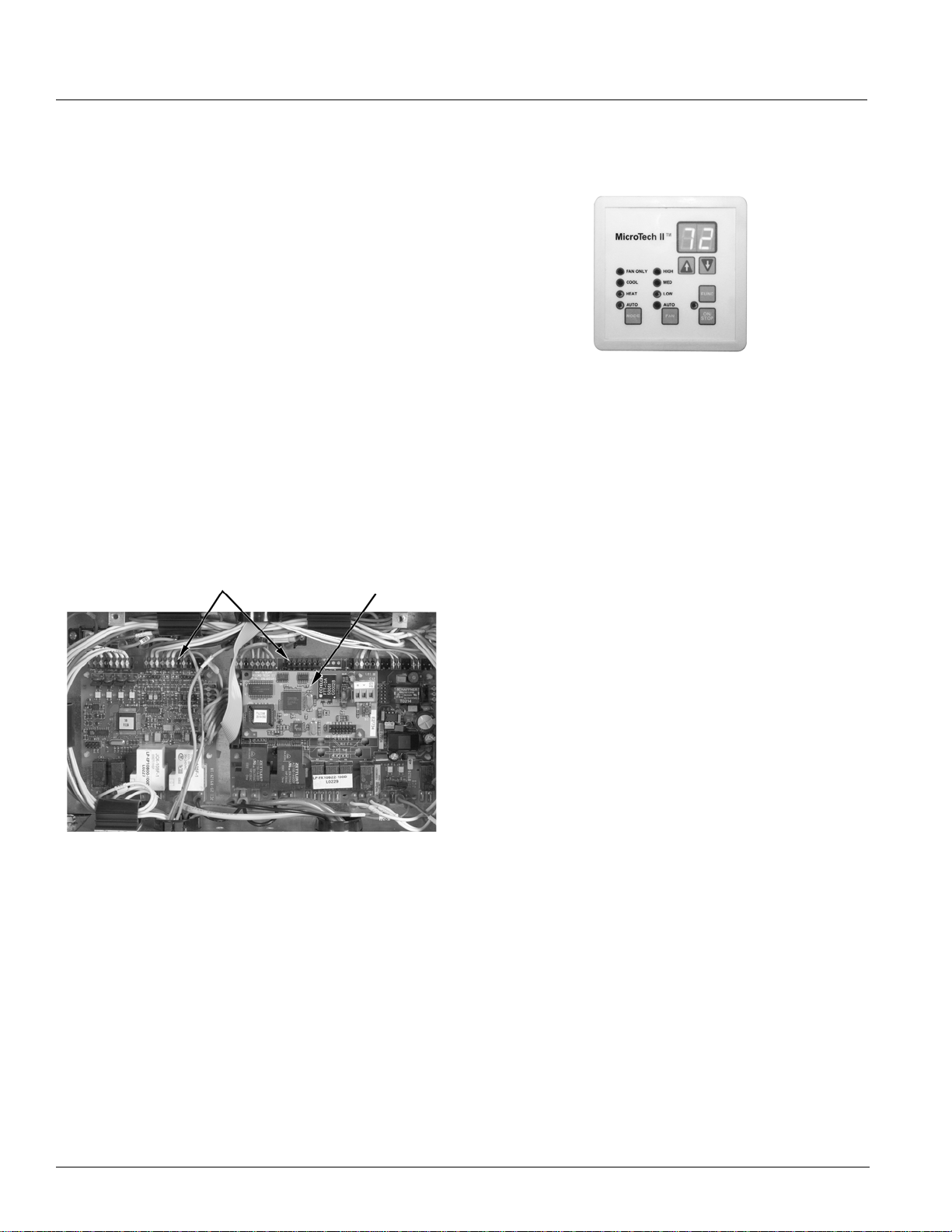
Figure 17. MicroTech II Control Board
Terminal Connections
Plug-In Control Module
Figure 18. User Interface To uc h Pad
The User Interface has individual touch-sensitive printed
circuit board mounted buttons, and comes with a built-in
menu structure (Hidden Key and Password Protected) to
change many of the common operating variables.
Four Operating Mode States
Four different user operating mode st ates can be chosen
on the LUI:
Heat: Heating and economizer operation only.
Cool: Cooling and economizer operation only.
Fan Only: Fan only operation.
Local User Interface
A built-in LUI touch pad with digital LED Display is
located in the right hand compartment below the top rig ht
access door. In addition to the Operating Mode States
and Fan Functions, the Touch Pad will digitally display:
he room set point temperature.
• T
• The current room temperature.
• Any fault code for quick diagnostics at the unit.
Auto: The unit automatically switches between heating,
cooling and economizer operation to satisfy the room
load conditions. The current unit state is also displayed.
Four Fan States
Four fan states are provided on all units: high, medium
low and Auto speed modulation. The Auto speed
function (part load, variable air) varies the fan speed
automatically to meet the room load whether the unit is in
heating, cooling or economizer mode.
All this is accomplished with
NEMA frame motor. A built-i n 10-minute delay helps
minimize awareness of speed changes. During low-load
or normal operation (about 60% of the time) the fan will
operate at low speed. The low speed operation, along
with GentleFlo fan technology, contributes to a very quiet
classroom environment.
When the load increases to an intermediate demand, the
cally shifts to the medium speed setting. At
fan automat
near-design or design-load conditions the fan will
operate on high speed.
With four fan states and GentleFlo fan technology, there
n
o need to oversize units or worry about
is
uncomfortable conditions.
i
a standard, single-speed
18 McQuay Catalog 1620
Page 19

MicroTech II Controls
Optional Communication Modules
Optional communication modules provide control and
monitoring information to your building automation
system without the need for costly gateways. Available
communication protocols include BACnet, LonTalk and
Metasys N2 Open. The communication modules for each
are described below.
Figure 19. Typical 2" x 4" Communication Module
BACnet MS/TP Communication Module
This module allows the UVC to inter-operate with
systems that use the BACnet (MS/TP) protocol with a
conformance level of 3. It meets the requirements of the
ANSI/ASHRAE 135-1995 standard for BACnet systems.
LONWORKS SCC Communication Module
This module supports the LONWORKS SCC (Space
Comfort Communication) profile number 8500-10. Unit
controllers are LonMark certified with this optional
ONWORKS communication module.
L
Metasys™ N2 Communication Module
This module provides N2 Open network communication
capability to the UVC for communication with Johnson
Metasys systems.
Sensors
The UVC is configured to use passive Positive
Temperature Coefficient (PTC) unit-mounted and wallmounted sensors. These sensors vary their input
resistance to the UVC as the sensed temperature
changes.
Figure 20. Wall-Mounted Temperature Sensors
Standard Expanded
Standard Sensor: This sensor has no remote setpoint
adjustment capability.
Expanded Sensor: This sensor has a remote room
setpoint adjustment of ±3°F (±1.5°C) from the room
setpoint established on the unit ventilator’s local user
interface touch pad. Five temperature settings are
provided on each side of center.
Humidity Sensors
On units equipped with humidity sensors, the UVC is
configured to use a 0-100% RH, 0 VDC, capacitive
humidity se
nsor. Humidity sensors are available as unitmounted only. The humidity sensors are used with units
capable of active dehumidification, or with units using an
outdoor enthalpy economizer or an indoor/outdoor
enthalpy economizer.
CO2 Sensor for Demand Controlled Ventilation
On units equipped for Demand Controlled Ventilation
(DCV) the UVC is configured to use a 0-2000 PPM, 0-10
VDC, single beam absorption infrared gas sensor. CO
2
sensors are available as unit mounted only. An air
collection probe (pitot tube and filter) is installed in the
return air of the unit.
Figure 21. CO2 Sensor For Demand Control Ventilation
Remote Wall-Mounted Temperature Sensors
MicroTech II unit ventilators offer three choices for
remote wall-mounted room sensors (Figure 20). Each
has a tenant override capability and comes with an
international, quick-
AAF-HermanNelson Model AZ Unit Ventilators 19
fastening connection capability.
Page 20

MicroTech II Controls
MicroTech II Sensor and Component Locations
Figure 22. MicroTech II Sensor and Component Locations
14
4
5
13
12
11
16
20
1 MicroTech II Unit Ventilator Controller (UVC):
(Located Beneath the Local User Interface Panel).
Factory mounted and run tested, microprocessorbased DDC control device capable of complete,
Stand-alone unit control, Master/Slave control, or
incorporated into a building-wide network using an
optional plug-in communication module. The UVC
supports up to 6 analog inputs, 12 binary inputs, and 9
binary outputs. The UVC expansion board supports
up to 4 additional analog inputs and 8 additional
binary outputs. Master/Slave units have the controller
factory configured for a local peer-to-peer network
between these units (network wiring between thes e
units needs to be field installed). Optional network
17
3
9
19
18
21
2
15
10
6
communication is provided via plug-in communication
modules that connect directly to the UVC.
2 Communication Modules (optional): (Lo
Beneath the Local User Interface Panel). Plug -in
network communication module that is attached to the
UVC via a 12-pin header and 4 locking standoffs.
Available communication modules:
ing Automation and Control Netw
• Build
net™) Master Slave/Token Passing
ork (BAC-
(MS/TP) Allows the UVC to inter-operate with systems that
use the BACnet (MS/TP) protocol with a conformance level of 3. Meets the requirements of ANSI/
AE 135-1995 s
ASHR
tandard for BACnet systems.
1
ated
c
7
20 McQuay Catalog 1620
Page 21

MicroTech II Controls
• LONWORKS™ compliant Space Comfort Controller
(SCC) – Supports the L
ONWORKS SCC profile num-
ber 8500-10.
etasys™ N2 Open – Provides N2 Open network
• M
communication capability to the UVC.
3 Local User Interface (LUI):
The LUI provides a unit
mounted interface which indicates the current unit
operating state and can be used to adjust the unit
ventilator operating parameters (operating mode,
temperature set points, fan speed, and occupancy
mode). The LUI features a 2-digit display, 7 keys (1
key is hidden), and 9 individual LED indicators.
4 Tenant Override Switch Pr
ovides a contact closure
that causes the unit to enter the “Occupied” operating
mode for a set time period (default = 120 minutes).
5Time Clock (
optional on stand-alone units only)
Factory mounted 7 day/24 hour, digital time clock with
up to 20 programs to sequence the unit ventilator
through occupied and unoccupied modes in
accordance with a user programmed time schedule.
6 External Signal Connection Plugs: (L
ocated
Beneath the Local User Interface Panel). Three multipin plugs are factory provided and pre-wired with amp
plug connections that plug into the wall sleeve.
Provided for field wiring of :
ote Wall Mounted Temperature Sensor
• Rem
(optional accessory).
rnal Input Signals (by others): unoccupied,
• Exte
remote shutdown, ventilation lockout, dew point/
humidity (night time operation) or exhaust interlock
signals.
rnal Output Options (by others): lights on/off,
• Exte
fault indication signal, exhaust fan on/off or au xiliary
heat signal.
Note: Not all external signal options can be used
simultaneously and may not be available on all software
models. Refer to the “UVC Input and Output Tables” in
IM 747 for available options.
7 Motor Speed Transformer: (Located Beneath the
Local User Interface Panel). Multi-tap autotransformer provides multiple fan motor speed control
through the LUI.
8 Unit Main Power “On-Off” Switch (not shown):
Shipped
with the wall sleeve accessory, the “On-Off”
switch disconnects the main power to the unit for
servicing or when the unit is to be shut down for an
extended period of time.
9 Fuse(s) - Fa
n motor and controls have the hot line(s)
protected by factory installed cartridge type fuse(s).
10 Control Transformer - (L
ocated Beneath the Local
User Interface Panel). 75 VA 24-volt NEC Class 2
transformer for 24 volt power supply.
11 Outdoor Air/Return Air Damper Actuator -
Direct
coupled, floating point (tristate) actuator that spring
returns the outdoor air damper to the closed position
upon a loss of power.
12 Face and Bypass Damper Actuator - Direc
t
coupled, floating point (tristate) actuator that is nonspring returned (Model AZQ only , other unit s are valve
control).
13 Hydronic Coil Low Air T
emperature Limit (T6
freezestat) – Factory installed on all units with
hydronic (water) coils. The T6 freezestat cuts out at
38ºF (+/- 3ºF) and automatically resets at 45ºF (+/3ºF).
14 Indoor, Direct Expansion (DX) Coil Refrigerant
emperature Sensor – The sensor is installed on the
T
unit ventilator’s indoor refrigerant coil on the right
hand side of the coil “u-bend”. It is used to sense low
refrigerant temperatures on the indoor coil.
15 Outdoor, Direct Expansion (DX) Coil Refrigerant
emperature Sensor - The sensor is installed on the
T
unit ventilator’s outdoor refrigerant coil on the right
hand side of the coil “u-bend”. It is used to sense the
refrigerant temperature on the outdoor coil.
16 Room Temperature Sensor - Th
e unit mounted
sensor is located in the sampling chamber (front,
center section) where room air is continuously drawn
through for prompt response to temperature changes
in the room. A remote wall mounted temperature
sensor is available for remote room temperature
sensing. (optional).
17 Discharge Air Temperature Sensor – The
sensor is
located on the second fan from the right to sense
discharge air temperatures.
18 Outdoor Air Temperature Sensor –
The sensor is
located in the outdoor air section of the unit before the
outdoor air damper. With network applications, the
unit mounted sensor can be overridden by a remote
sensor through the network.
19 Outdoor Air Humidity Sensor (o
ptional, standard
with expanded and leading edge controls) - Unit
mounted humidity sensor for units using expanded
outdoor enthalpy economizer or Le ad ing Edge in doo r/
outdoor, true enthalpy comparison economizer. The
sensor is located in the outdoor air section of the unit
before the outdoor air damper. With network
applications, the unit mounted sensor can be
overridden by a remote sensor through the network.
AAF-HermanNelson Model AZ Unit Ventilators 21
Page 22
MicroTech II Controls
20 Room Humidity Sensor (optional, standard with
expanded controls) – Unit mounted humidity sensor
for units capable of passive or active dehumidification
(Reheat) or with units using Leading Edge indoor/
outdoor, true enthalpy comparison economizer. The
sensor is located in the sampling chamber (front,
center panel) where room air is continuously drawn
through for fast response to humidity changes in the
room. With network applications, the unit mounted
sensor can be overridden by a remote sensor thro ugh
the network.
(
21 CO2 Sensor
optional) – Unit mounted, single beam
absorption infrared gas sensor with a sensing range
of 0 – 2000 ppm and voltage output of 0 to 10 VDC
(100 ohm output impedance). The pitot tube sensing
device is located in the unit ventilator's return air
stream. The optional CO2 sensor is used with the
UVC's Demand Control Ventilation feature to vary the
amount of outside air based on actual room
occupancy. With network applications, the unit
mounted sensor can be overridden by a re mote
sensor through the network.
ot
22 Control Valve(s) (n
shown) – Optional accessory
valve(s) may be either 2-position "End of Cycle"
(model AZQ) or modulating (model AZU and AZR), to
control the quantity of water through the coil. Available
in 2-way or 3-way configurations. Spring return
actuators are required for all hot water and steam
heating valves. All heating valves are normally open.
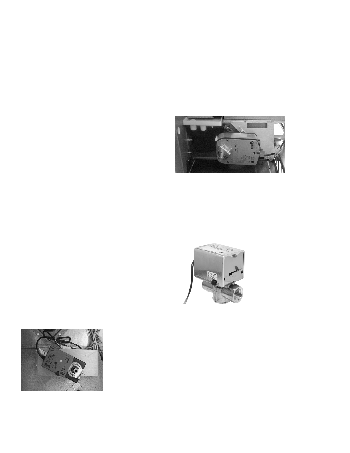
Outdoor Air/Return Air Damper (OAD) Actuator
The UVC is configured to operate a floating-point (tristate) direct-coupled actuator for the outdoor air damper.
This actuator provides spring-return operation upon loss
of power for positive close-off of the outdoor air damper.
To determine damper position, the UVC uses a separate,
factory-preset, configurable setting for each actuator's
stroke time.
Figure 24. Outdoor Air Damper Actuator
2-Position End-of-Cycle Valve Actuators (Optional)
On units equipped with 2-way or 3-way, end-of-cycle
(EOC) valves, the UVC is configured to operate 2position End-Of-Cycle (EOC) valve actuators
(Figure 25). Spring return actuator s are used fo r all End
of Cycle (EOC) valves. All wet heat EOC valves are
o
rmally open.
n
Figure 25. End of Cycle Valve Actuator
Actuators
Face & Bypass Damper Actuator
On units equipped with face & bypass damper control,
the UVC is configured to operate a floating-point (tristate), direct-coupled, face & bypass damper actuato r . To
determine the modulating damper position, the controller
uses a separate, factory-preset, configurable setting for
each actuator's stroke time.
Figure 23. Face & Bypass Damper Actuator
22 McQuay Catalog 1620
Page 23
MicroTech II Controls
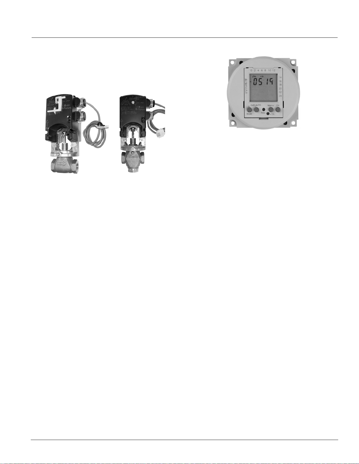
Modulating Valve Actuators (Optional)
On units equipped with modulating valves, the UVC is
configured to operate floating-point (tri-state) actuators
for modulating 2- way and 3-way valves (Figure 26).
Figure 26. Modulating Valve Actuator
2-Way Valve 3-Way Valve
s
Spring return actuators are used for all modulating
valves. All wet heat valves are normally open.
To determine modulating valve position
the UVC uses a
separate factory preset, configurable setting for each
actuator's stroke time. For accuracy of actuator
positioning, the UVC is provided with an overdrive
feature for the 0% and 100% positions and a periodic
(12-hour) auto-zero PI control loop for each modulating
actuator.
Optional Time Clock For Stand-Alone Units
As an option, stand-alone, non-servant un it ventilators
can be factory-equipped with a unit-mount ed, di g ital, 24hour/7-day time clock with 20 programs (Figure 27). The
clock is factory-wired to automatically
o
ccupied or unoccupied mode based upon its schedule.
Features of this clock include:
• Large keys with circular programming for easy
hedule setup
sc
• An LCD disp
lay
• Manual 3-way override (On/Auto/Off)
• Capacitor backup to retain pr ogram memory during
po
wer outages.
place the unit into
Figure 27. Optional Time Clock
ServiceTools™
ServiceTools for MicroT ech II Unit Ventilators is a CD
containing software for operation on a personal
computer. This software provides a visual schematic of
the unit, a pictorial representation of the sequence of
operation and enables the service technician to:
onitor equipment operation.
• M
• Configure network communications.
• Diagnose unit operating problems.
• Download application code and configure the unit.
Th
is software is a purchased tool for service technicians
and will run
on PCs with Windows
2000 (SP2), and NT4.0 (SP6) and XP (SP1) operating
systems. This tool is highly recommended for startup and
servicing. (It may be required for startup and/or servicing,
depending upon unit integration and other requirement s.)
It has no BAS functions, such as scheduling or trending,
and it cannot serve as a Work Station Monitoring
package.
ServiceTools comes with a service cable having two
rface conn
inte
ections:
• A 12-pin connection to the main control board.
• A 3-pin connection to the optional communication
ules.
mod
®
98 (Second Edition),
AAF-HermanNelson Model AZ Unit Ventilators 23
Page 24
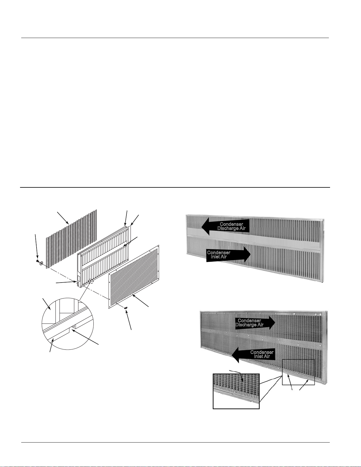
Accessories
Accessories
Wall Louvers & Grilles
The 16-gauge QS 5052 mill finish aluminum louver frame
is divided in half horizontally, with make-up and
discharge-air stream sections to reduce air recirculation
within the vertical louver blade. The upper half of the
louver has a blockoff on the exterior side to increase
discharge air velocity and improve the throw of leaving
air.
The vertical louver can be ordered with flanges that are
tached on the outside of all four sides of the lo uver,
t
a
resulting in a vertical dimension of 30" (762 mm). Weep
holes exist behind the bottom flange of the louver. A 1/2"
(13 mm) square aluminum wire mesh (bird screen) is
provided on the interior surface of the louver.
The vertical louver is fabricated from 20-gauge QS 5052
finish aluminum. The single piece blade has a turned
l
mil
edge along the entering and leaving surface to reduce
Figure 28. Typical W a ll Lo uver and Grille
Factory Mounted
Bird Screen
Bird Screen
Fasteners
Frame
Optional
Flanges
Splitter Lines
Up with Wall
Sleeve Splitter
visibility of the outdoor coil and fan section, and adds
rigidity to the blade. The 72° offset bend near the middle
of the blade creates an air-path turn that minimizes
moisture carryover, with a total blade depth of 2¼" (57
mm) in direction of airflow .
colors
The louver is available in the following
:
• Natural Aluminum finish (paintable QS 5052
Alumin
um)
• Autumn Brown - thermosetting urethane powder coat
aint electrostatically applied and oven-cured to
p
provide correct chemical cross-linking.
• Dark Bronze - thermosetting urethane powder coat
aint electrostatically applied and oven-cured to
p
provide correct chemical cross-linking.
• Clear Anodized Aluminum finish
Figure 29. Vertical Blade Louver Outside View, Without
Flange
Discharge Air
Outside View
Condenser
Information
Labels
Louver Blade
Bottom Flange
Bottom
Drain Notch
Optional Factory
Exterior Grille
Mechanical
Fasteners
Mounted
Condenser
Inlet Air
Figure 30. Vertical Blade Louver Inside View, Without
Flange
Bird Screen on
Side Toward Unit
Inside View
Condenser
Discharge Air
Condenser
Inlet Air
Louver with
Weep Holes
24 McQuay Catalog 1620
Page 25
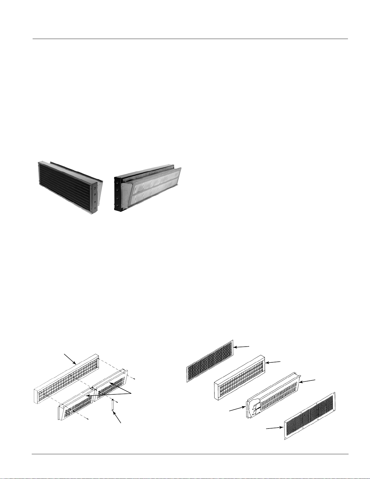
Accessories
VentiMatic™ Shutter Room Exhaust Ventilation
Outdoor air introduced by the unit ventilator must leave
the room in some way. In some states, exhaust vent s are
required by law or code to accomplish this. The
Ventimatic shutter is a more economical solution to the
problem.
The Ventimatic shutter is a continuously variable, gravity-
c
tuated room exhaust vent (Figure 31). It operates in
a
direct response to positive static ai
when ventilation air is brought into the room by the unit
ventilator. It is a “one-way” shutter that opposes any flow
of air into the room.
Figure 31. Ventimatic Shutter
The Ventimatic Shutter’s ability to exhaust only the
amount of air required results in considerable energy
savings. In the heating mode, the unit ventilator will be
able to bring in only the required percent minimum
outdoor air. Unlike systems that rely on powered
exhaust, no energy will be wasted heating excess
outdoor air . In the cooling mode, the unit ventilator will be
able to bring in 100% outdoor air for full natural or free
cooling when it is energy effective.
Since it is not powered, Ventimatic
inherently silent. Unlike other non-powered vents, it
opens at an extremely low positive pressure (0.005"). Its
shutter flaps are made of temperature-resistant glass
fabric impregnated with silicone rubber for flexibility and
r pressure created
Front (Indoor Side)Back (Outdoor Side)
Shutter’s operation is
long life. This fabric retains its original properties down to
-50°F.
Ventimatic Installation
The Ventimatic Shutter should be mounted on the same
wall as the unit ventilator. This neutralizes the effect of
wind pressure forcing excess air into the room through
the unit ventilator louver. That’s because the wind
pressure will also keep the Ventimatic Shutter closed and
prevent room air from escaping. Since the existing room
air cannot leave, excess air from the wind gust will not
enter. (In contrast, a powered exhauster would “assist”
the wind’s effect.) Same-wall mounting also minimizes
“short circuiting” of air flow that could occur with
opposite-wall mounting.
The Ventimatic Shutter is generally mounted on an AAF-
e
HermanN
then used for exhaust (Figure 32). For large unit
ventilators, two Ventimatic Shutters may be mounted
e
by side on the same wall louver to promote
sid
adequate exhaust air capacity. The size and appearance
of wall louvers and grilles used for unit ventilators and for
Ventimatic Shutters are identical and present an
architecturally coordinated and pleasing installation.
An ideal method of integratin
with the unit ventilator is to locate the shutter behind a
matching open-shelf or closed-shelf storage cabinet
mounted next to the unit ventilator . For example, 48-inchlength wall louver can be accommodated behind a 4foot-high storage cabinet. The cabinet should be ordered
with a slotted-type kick plate to provide a concealed
exhaust air path to the shutter. This combination will
enable a complete, integrated, energy-efficient HVAC
and room exhaust system.
lson wall louver (ordered separately) which is
e Ventimatic Shutter
g th
Figure 32. Ventimatic Shutter Installation
Aluminum Exterior
Louver
Two Shutter Assemblies
Mounted on One Louver
Aluminum Exterior
Grille (optional)
Center Cover
AAF-HermanNelson Model AZ Unit Ventilators 25
Steel Interior Grille
(optional)
Grille (optional)
Aluminum Louver
Baffle Plate
Page 26

Accessories
Storage Cabinets, Sink & Bubbler
AAF-HermanNelson storage cabinets are designed to
complement our classroom unit ventilators. They are
made from heavy-gauge steel and finished with
environmentally friendly, thermosetting urethane powder
paint that is available in a pleasing array of matching
architectural colors.
Storage Cabinets
Shelving cabinet tops are furnished with a textured, nonglare and scuff-resistant charcoal bronze electrostatic
paint. Optional laminate tops are available for these
cabinets and for field-supplied and installed countertops.
Other features include:
• Adjust
• Adjust
• Optional easy sliding doors with bottom glide track for
• Door pulls added for convenience and finished
Figure 33. Cabinet With Shelves
able kick plates with leg levelers are standard on
all un
its and functional accessories. European cabinet
design has adjustable leg levellers on each corner that
adjust to compensate for variations in the floor.
able-height metal shelves for flexible storage
sp
ace (Figure 33). Shelves can be adjusted without
tools by repositioning the four co
clips.
od alignment (Figure 34). Bottom glide track
go
prevents door bottom intrusion into the storage space.
nal door locks.
Optio
pearance.
ap
ncealed shelf holding
Sink & Bubbler Cabinet
Sink & bubbler cabinets have a one-piece stainless steel
top with stainless steel bowls, a raised front lip, and
formed back and end splash boards (Figure 35). You
have a choice of single or double bowls and optional
or
locks to conceal storage and piping. The adapter
do
back top, when furnished, has a charcoal textured finish.
Figure 35. Cabinet With Sink And Bubbler
End Panels
One-inch end panels are typically used to finish off
stand-alone floor units. Six-inch end panels with kick
plates can be used to provide extra space needed for
piping (Figure 36). All end panels are individually
wrapped in plastic and boxed to help prevent damage
rin
g construction.
du
Figure 36. End Panels
6" End Panel
Figure 34. Cabinet With Sliding Doors
Filler Sections
Filler sections can be used as spacing between cabinets,
walls and unit ventilators.
26 McQuay Catalog 1620
Page 27

Application Considerations
Application Considerations
Why Classrooms Overheat
Overheated classrooms occur every day in schools in
every area of the country. The most serious result is their
detrimental effect on students’ ability to concentrate and
learn. Research has determined that the ability to learn
and retain knowledge decreases rapidly as the
temperature exceeds recommendations. Overheated
rooms also represent wasted fuel, resultin g in exc es sive
operating costs.
Correcting an overheating problem in an existing building
ficult and expensive. It calls for redesign and
ry dif
is ve
alteration of the heating and ventilating system,
necessitating considerable renovation. This potential
problem should be recognized, understood and planned
for when heating and ventilating systems are designed
for new and existing buildings.
Schools Have Special Needs
Schools have unique heating and ventilating needs, in
large part because of their variable occupancy and
usage patterns. Fewer cubic feet of space is provided
per student in a school building than in any other type of
commercial or public building. School classrooms are
typically occupied only six hours a day, five days a week,
for only three-fourths of the year, with time out for
vacations. All in all, this represents approximately 15% of
the hours in a year that a classroom is occupied.
To understand the overheating problem in schools, one
first realize that the excess heat comes from what
must
is commonly termed “uncontrolled heat sources.” To gain
some perspective on how this affects heating and coo ling
decisions, let’s take a look at a typical classroom in the
northern section of the midwestern United States.
Suppose we have a classroom that is 24 by 38 feet with
10-foot ceilings
and 100 square feet of
along the outside wall. At an outside temperature of 0°F
and a desired room temperature of 72°F, let’s assume
the normal amount of heat loss from the room to the
outside is 55,000 BTUs per hour.
As the outside temperature changes, so does the
ount of heat that the room loses. This is represented
m
a
in Figure 37 by Room Heat Loss Line A, which ranges
from 55,000 BTU per hour at 0°F outside air temperatur e
at
to zero BTU
70°F. Obviously, if the heating system
were the only source of heat in the classroom, the
solution would be simple: The room thermostat would
cause the heating system to supply exactly the amount
of heat required to maintain the room at the thermostat
temperature setting. In reality, the introduction of excess
heat from a variety of uncontrolled sources makes the
challenge considerably more complex.
window area
Figure 37. Heat Gain vs. Heat Loss In Occupied
60,000
50,000
40,000
30,000
20,000
Room Heat Loss, BTU/HR
10,000
As this chart illustrates, even in very cold weather an occupied
classroom is more likely to require cooling than heating.
Classrooms
A
ROOM HEAT LOSS LINES
B
C
D
-10 0 10 20 30 40 50 60 70
Outside Air Temperature, °F
Temperature On Room
Heat Loss Line Above
Which Cooling Is
Always Required
10,000 BTU/HR
}
Possible Heat Gain From
Sun, Direct & Reflected
8,500 BTU/HR
}
Heat Gain From Lights
7,800 BTU/HR
}
Heat Gain From
Students
Heat From Students
Body heat generated by students in a classroom is one
of the three primary sources of uncontrolled heat. In a
typical classroom of 30 students, the amount of heat
given off at all times will vary according to factors such
as age, activity, gender, etc. A conservative estimate is
260 BTU per hour per pupil. Multiply this by 30 and you
get a total of 7,800 BTU per hour added to the room by
the students alone. This excess heat is noted in
Figure 37 as “Heat Gain from Students.”
Heat Gain From Lights
Heat emitted by the lighting system constitutes a second
uncontrolled heat source. Artificial lighting is needed in
most classrooms even during daylight hours to prevent
unbalanced lighting and eye strain. A typical classroom
requires approximately 2,500 watts of supplemental
lighting to provide properly balanced lighting. Fluorescent
lights add heat to the room at the rate of 3.4 BTU per
watt per hour , or a tot al of 8,500 BTU per hour. This extra
heat is represented in Figure 37 as “Heat Gain from
Lights.”
Add the heat gain from lighting to the 7,800 BTU
odu
intr
ced by student body heat and we now have an
extra 16,300 BTU/HR being introduced into the
classroom by uncontrolled sources. This heat gain
remains constant regardless of the outdoor air
temperature.
AAF-HermanNelson Model AZ Unit Ventilators 27
Page 28

Application Considerations
Solar Heat Gain
The sun is a third uncontrolled source of heat. And,
because it is neither positive nor constant, calculating its
contribution to the overall heat gain is difficult. Solar heat
gain can be the worst offender of the three in classrooms
with large windows. Indirect or reflected solar radiation is
substantial even on cloudy days, even in rooms with
north exposure, as a result of what is termed “skyshine.”
To get an idea of the potential effect of the sun, let’s
ssume that the solar heat gain in our hypothetical
a
classroom will peak at 240 BTU/HR per square foot of
glass area. If we then assume a glass area of 100
square feet and at least 100 BTU/HR per square foot of
glass for solar heat gain, we can calculate a very
conservative estimate of 10,000 BTU/HR heat gain
through windows. If we add this to the heat from the
lights and body heat, total heat gain adds up to 26,300
BTU/HR from sources other than the heating and
ventilating system. This is indicated in Figure 37 by the
top horizontal line, which intersects Room Heat Loss
ine A at approximately 37°F. This is a reasonable
L
estimate of the maximum uncontrolled heat gain that can
be received in the typical classroom from these common
heat sources.
The Analysis
From Figure 37 it is evident that, at an outside
temperature of 48°F or higher, the he
students and classroom lighting is sufficient to cause
overheating. This is true even if the classroom is
occupied at night when solar heat gain is not a factor.
But, since classrooms are occupied during the day, solar
addition provides heat in varying amounts even in
classrooms with north exposures. Consequently, the
heating and ventilating system in our typical classroom
must provide cooling at all times when the outdoor
temperature is above 48°F and at any time during colder
weather when the solar heat gain exceeds room heat
loss.
If we assume an average winter temperature of
proximately 33°F in the region where our typica l
ap
classroom is located, we know that, half of the time, both
night and day, the outside temperature will be above
33°F. However, since it is generally warmer during the
day, when school is in session, the heating and
ventilating system will be required to provide cooling for
this classroom during much of the time that the room is
occupied.
In this example, we’ve assumed that our classroom had
room heat loss of 55,000 BTU/HR at a design outdoor
a
air temperature of 0°F (Room Heat Loss Line “A”). Bear
at given off by 30
in mind, however, that the recen t trend in “energy-saving”
building design often results in rooms with lower room
heat loss, as indicated by Room Heat Loss Lines “B”, “C”
and “D.” At 0°F design outdoor air temperature:
om “B” has a room heat loss of 45,000 BTU/HR,
• Ro
• Ro
om “C” has a room heat loss of 35,000 BTU/HR,
• Ro
om “D” has a room heat loss of 25,000 BTU/HR.
Note the lowering of the temperature above which
cooling will
decreases.
We’ve noted that cooling is alway
“A” when outdoor air temperatures exceed 48°F. In
Classroom “B,” “C,” and “D” cooling is always required
when outdoor temperatures exceed 44°, 36°and 23°F,
respectively (Figure 37).
Now that we understand the reason for classrooms
rheating, the solution is simple: The heating and
ove
ventilating system must provide cooling to take care of
the heat given off in the classroom by uncontrolled heat
sources.
always be required as the room heat loss
s required in Classroom
Cooling The Classroom
The AAF-HermanNelson Unit Ventilator has become a
standard for heating and ventilating systems in schools
because it provides the solution for overheating
classrooms. The unit ventilator cools as well as heats.
During the heating season the outdoor air tempe rature is
nearly always below the desired room temperature. It
stands to reason then that the outsid e air should be use d
to provide the cooling necessary to keep classrooms
down to thermostat temperature.
The classroom unit ventilator does just that. By
rporating an automatically controlled outdoor air
inco
damper, a va riable quantity of outdoo r air is introduced in
the classroom, metered exactly to counteract
overheating. Since our problem is more one of cooling
than of heating, it is evident that more than just the room
heat loss must be determined to design a good heating
and ventilating system. The cooling requirements should
be assessed as well, and the free-cooling capacity of the
equipment specified along with the heating capacity
required. If this is done, the optimum learning
temperature can be maintained in each classroom.
28 McQuay Catalog 1620
Page 29

Application Considerations
Meeting IAQ Requirements
Good indoor air quality (IAQ), which is important in the
home and at work, is no less important to students and
faculty in schools. For the past several years, efforts to
reduce energy costs in new school buildings have seen
the use of tighter construction, sealed windo ws an d
heavier insulation. While these construction techniques
have helped reduce energy costs, tightly sealed
buildings, or envelopes, when combined with increased
use of recirculated air, can lead to unhealthy air.
For this reason, the American Society of Heating,
Refrigeration and Air Condition
now recommends 15 cfm of outdoor air per pu pil, a nd no
longer endorses the practice of little or no usage of
outdoor air.
It should be kept in mind that a properly designed
xhaust system is essential for avoiding indoor air quality
e
problems. Simply put, if room air is not being exhausted
in a prescribed fashion, fresh outside air cannot be
introduced into the room. Likewise, an excessive amount
of outside air will be admitted, wasting energy.
The AAF-HermanNelson Ventimatic sh
actuated room exhaust vent, can solve both these
problems. The Ventimatic shutter allows the correct
amount of outdoor air to be brought into the room while
maintaining a slight positive pressure in the room. This
slight positive pressure, maintained during normal
operation, can also help prevent the infiltra tion of
undesirable gases into the classr oom. See “VentiMatic™
Shutter Room Exhaust Ventilation” on page 25.
ing Engineers (ASHRAE)
utter, a gr avity-
Following ASHRAE Control
percentage of outside air. The heating coil capacity
controller then modulates to maintain the thermostat
setting.
If the room temperature rises above the thermostat
setting, th
damper opens beyond the minimum position to maintain
the thermostat setting.
EXAMPLE: For a 60°F entering air
and 70°F room temperature, with 30°F outdoor air
temperature, 25% outdoor air will produce the 60°F
mixture air temperature. When the outdoor air
temperature drops to 10°F, 12.5% outdoor air will
produce the 60°F mixture air temperature.
e heating coil is turned off and the outdoor air
mixture temperature
Night Setback
Substantial fuel savings can be realized by operating th e
unit ventilator system at a reduced room setting at night
and during other unoccupied perio ds, su ch a s we ekend s
and holidays. Units with steam or hot-water coils will
provide convective heat during the setback period. If the
space temperature falls below the setting of the
unoccupied thermostat, the unit fans will be brought on to
provide additional heat. Units with electric heat coils do
not provide convective heat. The electric coil and the unit
fans will be brought on to maintain the thermostat setting.
Typical Temperature Control Components
In general, unit ventilators require the following basic
DDC electrical components in order to operate on any of
the standard unit ventilator ASHRAE cycles of control.
The control components listed in this section are for
familiarization purposes only and should not be
construed as a bill of material.
Cycle II
ASHRAE Cycle II is a very economical sequence of
control because only minimum amounts of out door air
are heated and free outdoor air—natural cooling—is
available to offset the large internal heat gain associated
with the dense occupancy of classrooms.
AAF-HermanNelson unit ventilators are normally
rolled according to ASHRAE Control Cycle II.
cont
ASHRAE control cycles apply only to heating, heatingand-ventilating and free-cooling operation. (For more
information on the ASHRAE Control Cycle II sequence,
see Figure 42 on page 36.)
Under ASHRAE Cycle II, the outdoor air damper is
during warmup of the room. As the room
closed
temperature approaches the thermostat setting, the
outdoor air damper opens to a predetermined minimum
AAF-HermanNelson Model AZ Unit Ventilators 29
Outdoor Air Damper Actuator
This is a modulating device under the control of the room
and discharge sensors. It positions the outdoor air
damper to admit the amount of outdoor air required at
any given point in the control cycle. The room air damper
is mechanically linked to the outdoor air damper, which
permits the use of a single actuator. Electric actuators
should be of the spring-return type so that the out door air
damper closes whenever the electric power supply to the
unit is interrupted.
Discharge Airstream Sensor
This device overrides the room sensor and modulates
the outdoor air damper toward the closed position when
the unit discharge air falls to a potentially uncomfortable
temperature.
Page 30

Application Considerations
Temperature Modulation Devices
The temperature of the air entering the room is
modulated using one or more of the following devices:
Face and Bypass Damper Control: A modulating
damper actuator, under control of the room sensor,
positions a face and bypass damper to control the
amount of air that passes through or around the unit coil.
Valve Control : A modulating valve, under control of the
room sensor, regulates the flow of steam,or hot water
through the unit coil.
Electric Heat Step Control: A modulating step controller,
under control of the room sensor, steps individual electric
heating elements on and off as required. Staging relays
are sometimes used in lieu of a step controller.
Note: When unit ventilators containing electric heat are
ordered without controls (controls by others) the
contractors and relays used for staging the electric heat
are not provided. This is because the number of stages
varies based on the type and manufacturer of the control
devices. It is not possible to pre-engineer contractors
and relays for all of these variables. The control
contractor is responsible for making certain that the
controls correctly control the unit’s functions.
Room Temperature Sensor
The room temperature sensor is a device that modulates
the intensity of a pneumatic or electric signal to the
controlled components within the unit to maintain the
room sensor’s comfort setting. Room sensors can be
mounted on the wall or within the unit.
Additional Components
Additional components may be required depending on
the specific application. They include:
Room Temperature Sensor Chamber: When the Room
Temperature Sensor is to be mounted within the unit
ventilator rather than on the wall, it is located behind a
series of holes in the unit front panel with the sensing
element sealed within the room temperature chamber.
The room temperature chamber is a standard feature
with units furnished with MicroTech II controls.
Low Temperature Protection: A low temperature limit or
freezestat senses the discharge air temperature off the
hydronic coil. If the temperature drops below 38°F, the
unit ventilator will shut down, closing the outdoor air
damper and opening the heating valve.
DX Cooling Control : This sequence switch in the
cooling control circuit energizes the condensing unit
contactor on a call for mechanical cooling.
DX Cooling Low Ambient Lockout: This lockout must be
used on DX split systems to lock out the condensing unit
when the outdoor air temperature is below 64°F
(17.5°C). This device must be integrated into the control
system so that the unit has full ventilation cooling
capability during the lockout period.
DX Low Temperature Limit : This limit must be used on
DX split system cooling units to de-energize the
condensing unit (compressor) when the refrigerant falls
below freezing. DX units with MicroTech II controls have
a factory-installed sensor on the return bend of the DX
coil that provides a sample of the coil’s temperature.
30 McQuay Catalog 1620
Page 31

Application Considerations
Meeting IBC Seismic Requirements
AAF-HermanNelson unit ventilators can be specified, as
follows, to meet International Building Code seismic
requirements:
• All components included in these unit ventilators are
signed, manufactured and independently tested,
de
rated and certified to meet the seismic compliance
standards of the International Building Code.
mponents designated for use in systems that are life
• Co
safety
, toxic, high hazard, combustible or flammable
meet the on line, anchorage and load path
requirements for life safety as defined in IBC sections
1621.1.6, 1621.3.3,1707.7.2. and IBC Commentary,
Volume II, section 1621 .1.6, IBC notes pertaining to the
release of hazardous material.
• All co
Figure 38. Seismic Installation
mponents used as part of a system ot her than the
ove meet as a minimum, all load path and
ab
anchorage standards for components as outlined in
IBC section 1621.3.3 & 1707.7.2.
Left End Compartment Area for Securing Unit to Floor
• All completed
labeled for field inspection. Seismic Compliance
Labels include the manufacturer's identification,
designation of certified models, definitive information
describing the product's compliance characteristics,
and the Independent Certifying Agency's name and
report identification.
In addition to all seismic requirements for IBC
Certification listed els
submittals for these units include:
1 A Certificate of Compliance from the Independent
ifying Agency clearly indicating that components
Cert
supplied on this project are included in the component
manufacturer's Certificate of Compliance.
2 Clear inst
components that are part of the overall component
installation.
component assemblies are c
where in the project specification,
e
allation instruc
tions including all accessory
learly
Right End Optional
Caster
Right End Compartment Area for Securing Unit to Floor
Right End Compressor
Compartment
1/4"dia. x 2" x 5/16"
Hex Washer Head
Concrete Screw – 2
AAF-HermanNelson Model AZ Unit Ventilators 31
Page 32
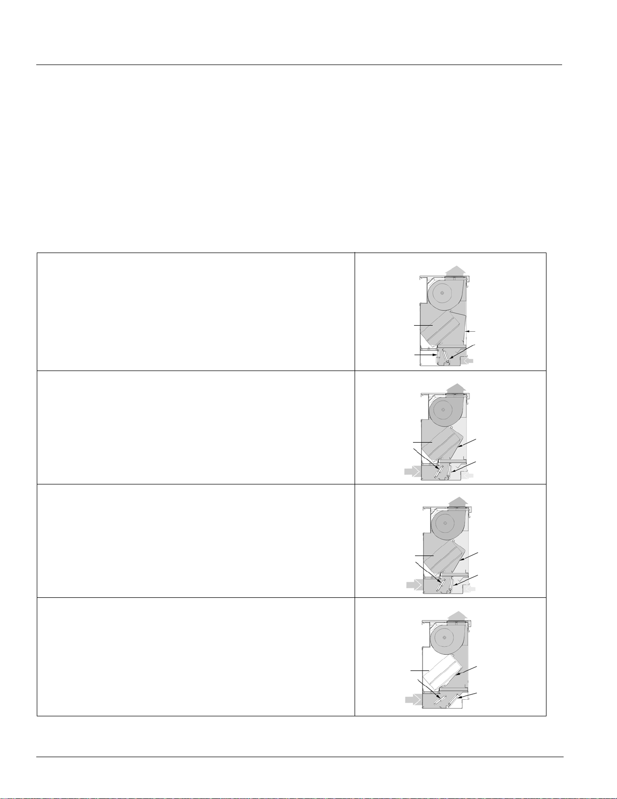
Application Considerations
Face & Bypass Temperature Control
Precise Environment Control
Face and bypass damper control units utilize standard
when less heat is required. All air bypasses the coil when
“free” cooling or no heating is required.
unit ventilator cycles of temperature control and bring in
up to 100% fresh outdoor air for ventilation (free) cooling
of the classroom. The bypass damper allows all air to
pass through the heating coil for fast warm-up. A portion
passes through the coil and a portion bypasses the coil
Figure 39. Face & Bypass Temperature Control
Morning Warm-Up
Figure A shows the face and bypass damper, the room air damper,
and the outdoor air damper positioned for “morning warm-up/cooldown.” During the summer the unit is cooling; in winter it is heating.
When the room air temperature is above (cooling) or below (heating)
the sensor setpoint, the face and bypass damper is open to the coil.
At the same time, the outdoor air damper is closed and the room air
damper is open. All air handled by the fan passes through the coil for
maximum heating or cooling.
Maximum Heat Or Cool, Minimum Outdoor Air
Figure B shows the damper positions as the room temperature
approaches the room thermostat setting. The outdoor air damper is
open to the minimum setting and the room air damper closes slightly.
Unit ventilators normally admit the same minimum percentage of
outdoor air during the mechanical cooling cycle as during the heating
cycle.
Minimum Outdoor Air, face and bypass Damper Modulation
Figure C shows normal operation. Room temperature is maintained
within the operating range. Under these conditions, the outdoor air
and room air dampers retain their same positions while the face and
bypass damper modulates to provide accurate room tem p er at ur e
control. (heating only)
Full Outdoor Air (Free Cooling)
Figure D shows the damper positions for maximum ventilation coo ling.
When uncontrolled heat sources tend to overheat a room (such as
people, lights or sunlight), the face and bypass damper will bypass
100% of the air around the heat transfer element. The end-of-cycle
valve (if furnished) will be closed to the coil. The outdoor air damper
will position itself for additional outdoor air, up to 100% of the fan
capacity, as required by the room cooling needs. As the outdoor air
damper opens, the room air damper closes proportionally.
A
A
Side
Side
Coil
Coil
Outdoor Air
Outdoor Air
Damper Closed
Damper Closed
B
Side
Outdoor Air
Damper
Outdoor Air
C
Side
Outdoor Air
Damper
Outdoor Air
D
Side
Coil
Outdoor Air
Damper
Outdoor Air
100% Room Air
100% Room Air
Minimum Outdoor Air
Coil
Minimum Outdoor Air
Coil
100% Outdoor Air
Room SideOutdoor
Room SideOutdoor
Face & Bypass
Face & Bypass
Damper
Damper
Room Air
Room Air
Damper
Damper
Room Air
Room Air
Room SideOutdoor
Face & Bypass
Damper
Room Air
Damper
Room Air
Room SideOutdoor
Face & Bypass
Damper
Room Air
Damper
Room Air
Room SideOutdoor
Face & Bypass
Damper
Room Air
Damper Closed
32 McQuay Catalog 1620
Page 33

Application Considerations
Ease Of System Balancing
With face and bypass damper control, the water in the
system is constantly circulating, which maintains a
desirable head pressure to the pumps. With fluctuating
head pressure eliminated, balancing the sys te m ca n
enable the correct quantity of water in all circuits.
Two Stage Compressors
Our self-contained units with the two-stage compressor
will run on lower fan speeds up to 70% of the time,
improving comfort through better humidity control and
quieter operation, while minimizing issues with over
sizing. The unit is designed to operate in low
compression mode while in medium and low fan speed.
The reduced cooling capacity in the medium and low fan
speed will allow the system to run longer at moderate
and low load conditions providing better humidity contro l.
When the high capacity is needed the high speed will
provide high compression and full capacity cooling.
Reduced Risk Of Coil Freeze
With face and bypass damper control, there is no change
in the flow of water through the coil. Coils that have a
constant flow of water cannot freeze. On valve control
units, water left in the heating coils after the modulating
temperature control valve shuts can freeze and rupture
the coil.
Additional freeze protection is afforded by AAF-
manNelson’s double-walled cold weather outdoor
Her
damper. It has encapsulated insulation and wool mohair
end seals to help prevent unwanted cold air from
entering the unit.
A low-temperature freezestat, factory installed on all
ronic units, significantly reduces the chance of coil
hyd
freeze-up. Its wave-like configuration senses multiple
locations by blanketing the leaving air side of the coil to
react to freezing conditions.
AAF-HermanNelson Model AZ Unit Ventilators 33
Page 34
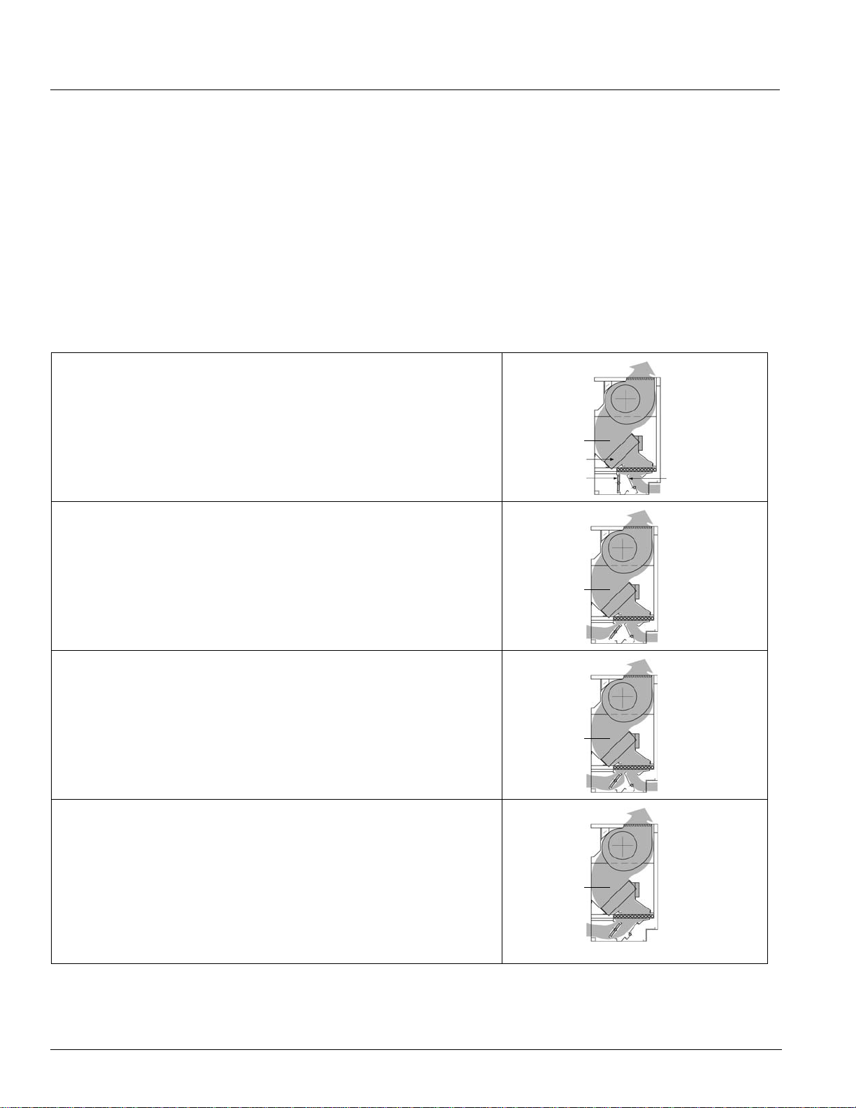
Application Considerations
D
Modulating Valve Temperature Control
Modulating Valve Control With Hot Water Or Steam
control valve and all air handled by the unit will pass
through the heating coil at all times.
The description of unit operation given for dampercontrolled units is correct for valve-controlled units
except that references to face and bypass dampers and
end-of-cycle valves should be disregarded. The capacity
of the heating coil will be regulated by a modulating
Hot Water Reset
Hot water system controls should include a provision for
resetting the temperature of the supply hot water in
relation to the temperature of the out door air. A hot water
temperature of 100°-110°F, is suggested when the
Figure 40. Modulating V al v e Temperature Control
Morning Warm-Up
Figure A shows the modulating valve allowing full flow through the coil
and the room air damper and outd oor air damper positioned fo r morning
warm-up. In the summer, this is full cooling; in the winter, it is full
heating. When the room temperature is below the setpoin t (heating),
the valve opens for full flow through the coil. All air is directed through
the coil(s).
Minimum Heating
Figure B shows the outdoor air damper moved to its minimum position.
The modulating valve is still allowing full flow through the coil. Unit
ventilators normally admit the same minimum percentage of outdoor air
during the heating cycle as during the mechanical cooling cycle. All the
air is directed through the coils.
Minimum Outdoor Air
Figure C shows normal operation. Room temperature is maintained by
modulating the flow through the coil (heating only). The outdoor and
room air dampers maintain the same positions and all air is directed
through the coils.
A
Side
100%
Room Air
Coil
Outdoor Air
Damper Closed
B
Side
Mixed Air
Coil
Outdoor Air
C
Side
Mixed Air
Room SideOutdoor
Room Air
Room SideOutdoor
Room Air
Room SideOutdoor
Outdoor Air
Room Air
Full Outdoor Air (Free Cooling)
Figure D shows the modulating valve closed, allowing no flow through
Side
Room SideOutdoor
the coil. The outdoor damper is fully open and the room air dampe r is
closed. The sensor setting dictates when the out door damper needs to
begin closing. When the minimum outdoor damper position is reached,
the valve needs to modulate towards the full open position. All the air is
directed through the coils. (Care must be taken to ensure coils are not
exposed to freezing air conditions when the modulating valve is shut or
100%
Outdoor Air
Outdoor Air
Coil
no water is flowing through coils. See “Freeze Protection” on page 35.)
34 McQuay Catalog 1620
Page 35
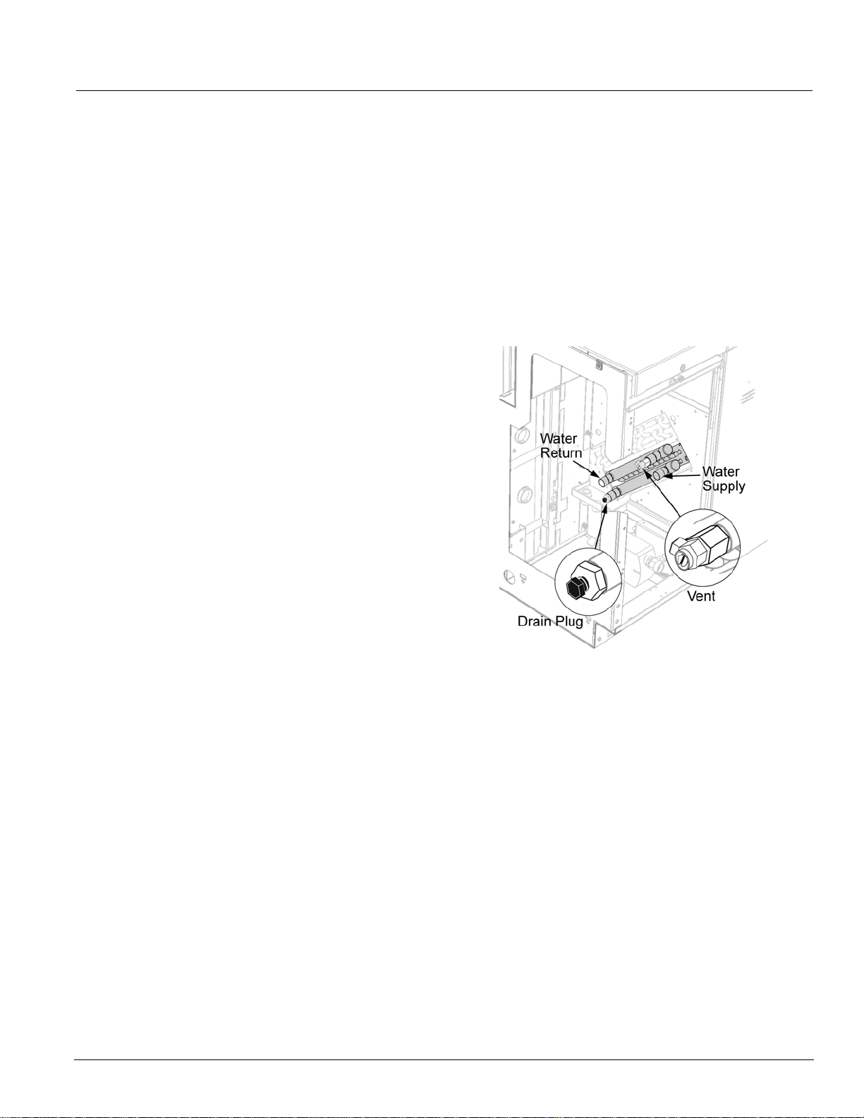
Application Considerations
outdoor air temperature is 60°F. The upper limit of the hot
water temperature will be dictated by the winter design
conditions.
The need for hot water reset controls
applications involving unit ventilators with face and
bypass control. Valve control performance will be
improved as well. When the supply water temperature is
far in excess of that required to offset the heat loss of the
space, the smooth modulating effect of the control valve
is lost. The control valve will cycle between slightly open
and fully closed. The effect of heat conduction through a
closed valve will also be reduced when hot water reset is
used.
is not limited
to
Freeze Protection
System freeze protection is an important consideration
on units utilizing hydronic coils. On valve-controlled units,
water left in the heating coils and exposed to freezing
outdoor air after the modulating valve shuts can freeze
and rupture the coil. Flowing water will not freeze. In
addition, it is very important to correctly size the
modulating control valve and control the supply water
temperature to provide constant water flow. If this
situation cannot be guaranteed, an antifreeze solution
must be employed to reduce the possibility of coil freeze.
ventilation requirements. Tuned internal flow and a
balanced header design, together with additional surface
area in the air stream, increase heat transfer to satisfy
the increased need for heat.
A manual air vent is located on the top of the coil header
hydr
of all floor
be purged from the coil during field start-up or for
maintena
A manual drain plug (Figure 41) is provided at th e bottom
of the coil header for coil drainage. Some competitors
y no
ma
Figure 41. Manual Air Vent & Drain Plug
t provide for drainage of coils.
onic coils. (Figure 41). This allows air to
nce.
Coil Selection
An extensive choice of coil offerings means that, with
AAF-HermanNelson unit ventilators, room conditions can
be met using almost any cooling or heating source . All
coils are located safely beneath the fans and are
designed for draw-thru air flow. All coils have their own
unshared fin surfaces (some manufacturers use a
continuous fin surface, sacrificing proper heat tr an sfe r) .
The result is maximum efficiency of heat transfer, which
promotes comfort and reduces operating costs.
An air break between coils in all AAF-HermanNelson
n
its is used to enhance decoupling of heat transfer
u
surfaces—providing full capacity output, comfort and
reduced operating costs.
All water, steam and direct expansion (DX) coils are
s
tructed of aluminum fins with a formed, integral
con
spacing collar. The fins are mechanically bonded to the
seamless copper tubes by expansion of the tubes after
assembly. Fins are rippled or embossed for strength and
increased heat transfer surface.
High-Quality Water Coils
AAF-HermanNelson coils rely on advanced heat transfer
to provide extra heating capacity for today’s increased
Long Lasting Electric Heating Coils
With our draw-thru design, electric coils are directly
exposed to the air stream. They come with a built-in
switch to de-energize the coil when the center front panel
is removed. A unit-mounted disconnect switch is
included. A continuous electric sensory element for high
temperature is not required because the air is drawn
smoothly and evenly across the coils, prolonging life.
(Blow-thru designs use cal rods inserted into the tube of
a fin tube coil that results in reduced heat transfer. The
constant movement of the electric heating cal rod with in
the tube shortens life.)
Even Distribution Steam Coils With V acuum Breakers
Steam distribution coils provide even distribution of
steam and even discharge air temperatures. A vacuum
breaker relieves the vacuum in the steam coil to allow
drainage of condensate. This eliminates water hammer
and greatly reduces the possibility of coil freeze-up.
AAF-HermanNelson Model AZ Unit Ventilators 35
Page 36
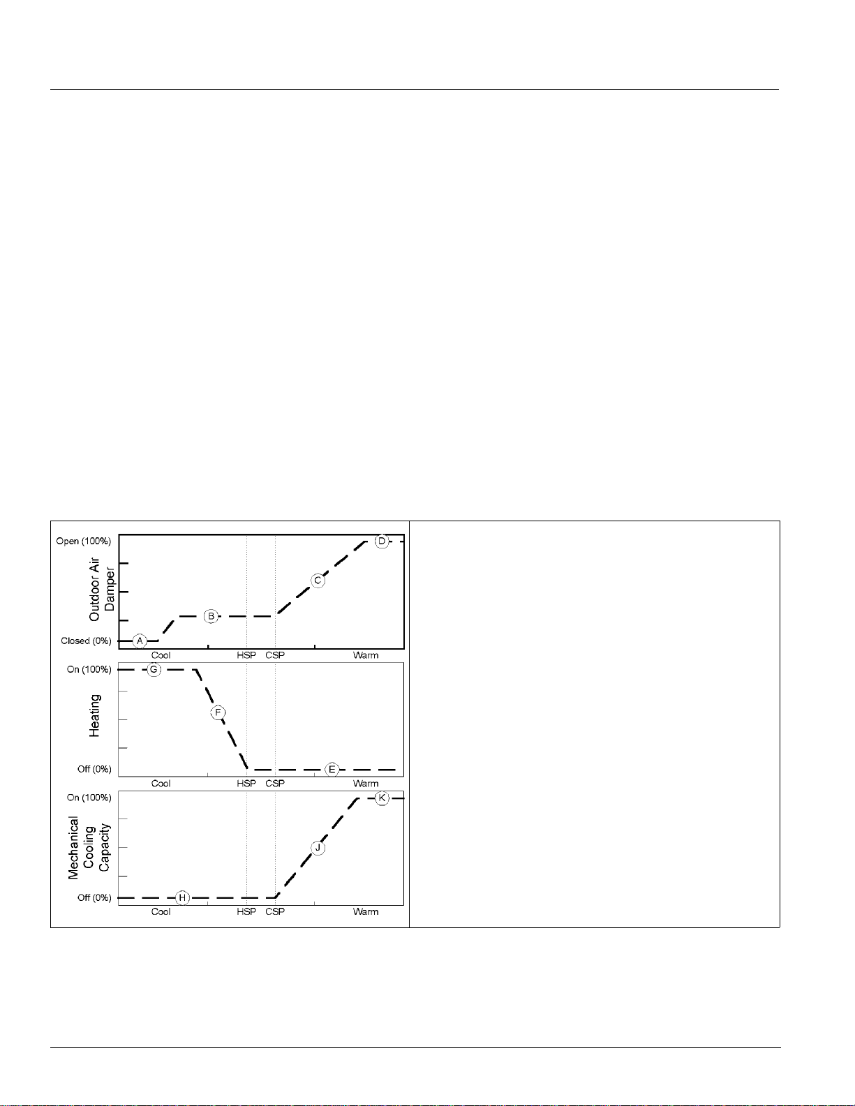
Application Considerations
ASHRAE Cycle II
We strongly recommend that ASHRAE Cycle II be
implemented with all unit ventilators using controls by
others. ASHRAE Cycle II is a very economical sequence
since only the minimum amount of outside air is
conditioned and free natural cooling is available. See
Figure 42:“ASHRAE Cycle II Operation” on page 36.
During warm-up (any classroom temperature 3°F or
below heating setpoint), the outdoor air damper is
re
mo
closed and the unit conditions only room air. As room
temperature approaches the heating setpoint the out door
air damper opens to a position that permits a
predetermined minimum amount of outside air to be
drawn in. Unit capacity is then controlled as needed to
maintain room setpoints. If room temperature rises
above room cooling setpoint, and the outside air is
adequate for economizer cooling, then the outdoor air
damper may open above the minimum positio n to
provide economizer cooling.
ASHRAE Cycle II requires that a minimum of three
ature measurements be made:
per
tem
Figure 42. ASHRAE Cycle II Operation
ssroom temperature.
1 Cla
2 Unit discharge air temperature.
3 Outdoor air temperature.
Add
itionally, the control sequence should incorporate a
Discha
rge Air Low Limit function which requires a
discharge air temperature sensor and can override
classroom temperature control in order to maintain a
discharge air temperature setpoint of 55°F (ventilation
cooling 45°F mechanical cooling).
When the discharge air temperature drops below 55°F,
harge-air low-limit function will disable cooling (if
c
the dis
enabled) and modulate the unit’s heating capability as
needed to maintain the 55°F discharge-air setpoint
regardless of room temperature.
If the unit’s heating capability
reaches
100%, then the
discharge air low-limit function will modulate the outdoor
air damper toward closed to maintain the 55°F discharge
air setpoint. Outdoor air temperature is used to
determine when to use economizer as a first stage of
cooling, and when to use mechanical or hydronic cooling
as the first stage of cooling.
Typical Outdoor Air Damper Operation
A Outdoor air damper closed.
B Outdoor air damper at minimum position.
C Economizer function is increasing the outdoor air
d
amper position.
Note: If outdoor air temperature is not adequate for free cooling,
secondary mechanical cooling can be used in place of
economizer cooling. A low discharge air function is used to
help maintain comfort and provide additional equipment
protection by preventing the discharge air from falling too
low (typically 55°F), and may force the outdoor air damper
toward closed to maintain the discharge air temperature
regardless of room temperature.)
D Damper is at full open.
Typical Heating Operation
E Heating capa
bility is closed (or off).
F Heating begins to modulate (or on).
G Heating capa
Typical Mechanical Cooling Operation
bility has reached 100%.
H M echanical cooling (DX) is closed (or off).
Mechanical cooling (DX) has reached 100%.
J
End-Of-Cycle (EOC) Valve Operation
The intended purpose of an EOC valve is to reduce the
chances of conductive radiant overheating which can
36 McQuay Catalog 1620
occur when the face and bypass damper is in the full
bypass position (i.e., no heating).
A heating EOC valve must be used on units with DX
cooling coup
led with steam or hot water heat and face
Page 37

Application Considerations
and bypass damper temperature control. It is optiona l for
the remaining models. However, it is strongly
recommended that heating or heat/cool EOC valves be
used on all face and bypass units with heating capability
to prevent overheating.
Heating EOC Valve
For steam or hot water heat only with face and bypass
damper control; steam or hot water heat with face and
bypass damper control coupled DX cooling:
The heating EOC valve should be a normally open,
ing return (open), two position valve. In addition:
spr
1 Heating Operation: Wh
2°F or more below the heating setpoint, the EOC
valve should open and remain open until the room
temperature becomes equal to the heating setpoint or
higher.
2 Operation Due To Outside Air Temperature: If
outside air temperature is equal to or less than 35°F,
the EOC valve should open, the EOC should then
remain open until the outdoor air temp erature reaches
37°F. or higher.
en the room temperature is
the
Water Coil Low Air Temperature Limit (Freezestat) Operation
The Water Coil Low Air Temperature Limit, or freezestat,
function is intended to help protect the water coil from
extremely low air conditions. All units with hydronic coils
ship with a freezestat. The freezestat has a cut-out
temperature setting of no less than 38±3°F and a cut-in
temperature setting of approximately 48±3°F. The
freezestat is intended as a backup in case the normal
operating controls fail to protect the equipment. It is used
in the following manner:
DX Cooling With Hot Water Heat & Face and Bypass
Control:
of the hot water heating coil. When the freezestat cuts
out due to low temperatures, the following should occur:
• T
• T
• The
• The
maintain space temperature.
When the freezestat cuts in after cut-out, normal
op
The freezestat is secured to the leaving air face
he compressor is de-energized.
he outdoor air damper is closed.
heating EOC valve is forced to full open.
face and bypass damper modulates as needed to
eration may return.
Valve Control Applications
System freeze protection must be considered on valve
controlled units utilizing hydronic coils. Non-flowing water
in heating coils that are exposed to freezing outdoo r air
can freeze and rupture the coil (after the modulating
valve shuts). The modulating control valve must be
correctly sized and the supply water temperatu r e
controlled to ensure constant water flow. If this cannot be
guaranteed, use an antifreeze solution to eliminate the
possibility of coil freeze.
DX Cooling With Hot Water Heat & Valve Control: The
freezestat is secured to the leaving air face of the hot
water heating coil. When the freezestat cuts out due to
low temperatures, the following should occur:
he compressor (condensing unit) is de-energized.
• T
• T
he outdoor air damper is closed.
• T
he unit fan is de-energized.
• T
he heating valve is forced to full open.
• Wh
en the freezestat cuts in after cut-out, normal
operation may return.
Unit Installation
Carefully arrange the location and installation of each
model AZ unit to provide convenient service access for
maintenance and, if necessary, removal of the unit. The
installation consists of four basic elements in the
following order:
uver
1 Lo
2 Galvanized W
rizontal Air Splitters by others (if required)
3 Ho
4 AZ Self-cont
The louver brings in outdoor air for the condense r fan
section an
providing a path for heated condenser air to exit.
The Wall Sleeve secures the unit, provides a watertight
d air tight seal to the building and brings in electrical
an
and control wiring (if required). It contains the unit main
power disconnect switch which is located in the wall
sleeve junction box. All field electrical connections are
made inside this box.
Horizontal Air Splitters provide proper air paths and
min
The AZ self-contained unit ventilator provides comfort
coo
designed to be installed into or up against an exterior
wall. The louver, air splitters (if required) and wall sleeve
are installed before the AZ unit is install ed.
On many jobs, the louver and wall sleeve are shipped
ead of the unit itself. Installation instructions for these
ah
components are shipped with the individual components
included in this publication.
The following are general instr
applications. In all cases, good engineering practices
and local codes must be followed.
d ventilation air to the classroom while
imize air recirculation.
ling and heating for the space. The Model AZ unit is
all Sleeve
ained Unit Ventilator
uctions for suggested
AAF-HermanNelson Model AZ Unit Ventilators 37
Page 38
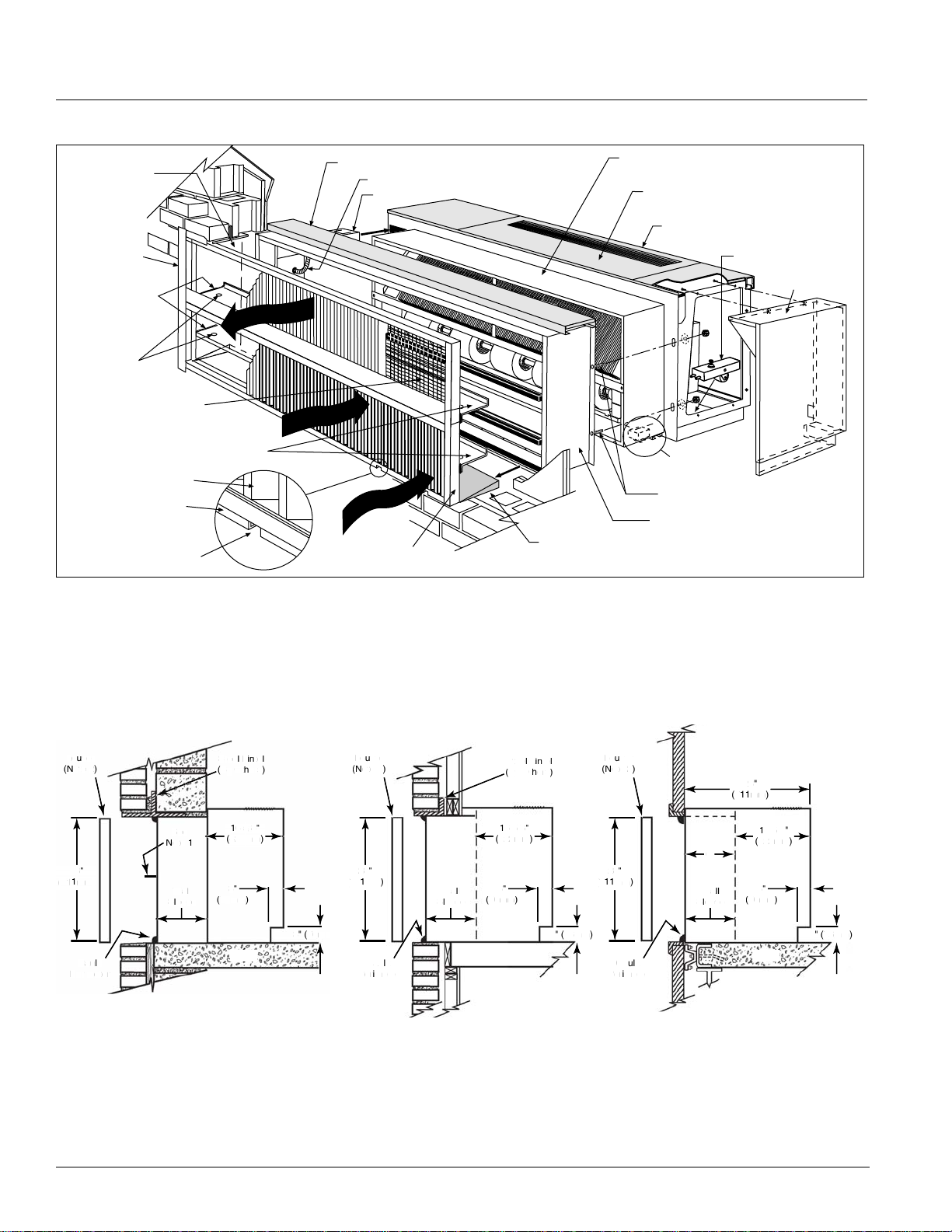
Application Considerations
L
o
u
v
(
t
e
)
8
S
t
e
ete
(
B
y
O
t
her
)
C
l
k
Per
e
t
r
S
e
e
N
1
S
l
eve
1
65/
8
(
422mm
)
3
(
76m
m
3
(
6
m
)
L
o
u
ver
(
o
t
e
)
8
)
C
a
Per
i
t
e
r
t
e
e
lLi
n
t
e
l
(
B
y
O
t
her
s
)
Wal
S
l
e
eve
1
65/
8
(
422mm
)
3
(
76m
m
)3(
76m
m
)
r
)
)
u
l
k
m
ete
r
l
S
l
e
6
5/8
(
)
2
8
(
)
C
3
(
76m
)3(
6
m
m
)
L
o
u
v
(
t
e
8
C
a
Per
i
Figure 43. Typical Self-Contained Unit Ventilator Installation
Internal Column for
Wall Bracing and
Anchoring (by others)
Optional Louver
Flange
Seal Horizontal Air
Splitters to Building
at Both Ends
Drain Holes in Splitters
(by others)
Louver–Bird Screen
3. Horizontal Air Splitters
(Field Made to Job Conditions by
Others) Pitch Down Toward Louver
Louver Blade
Bottom Flange
Weep Holes
Condenser Discharge
Condenser Supply Air
Textured Charcoal Bronze Unit Projection Top
(Except Fully Recessed Wall Sleeve)
Conduit (by others)
Wall Sleeve Junction Box
r
Outside Ai
1. Louver
Must be sealed watertight at top and both ends
Galvanized Condenser (Outdoor) Section
Textured, Scuff Resistant, Charcoal
Bronze, Environmentally Friendly Thermosetting Urethane Powder Paint Top
4. AZ Self-Contained Unit Ventilator
Caster on
Outdoor Section
Wall Sleeve Threaded Studs for
Fastening to Unit (Ships on Wall Sleeve)
2. Galvanized Wall Sleeve
Sealed Cement Mortar, Pitched
Away from Unit Toward Louver
Caster Kit for
Indoor Section (Optional)
6" End Panel
(Optional)
Wall Louvers
The outdoor air wall louver is usually set directly back of
the unit ventilator. The position of the wall louver is
determined in general by the building construction. The
top of the lower channel of the louver frame should be at
Figure 44.
Louver
o
(Note 2)
28"
(1m)
(711mm)
Caulk
Perimeter
Notes:
1 Horizontal splitter (by others) must be installed whenever there is any
space between the wall sleeve and the louver. It is also necessary to seal
the ends of the wall opening.
2 The top and two sides of the louver must be caulked watertight. Do not
ca
details.
3 Louvers may be recessed a maximum of 2" (51mm) from the exterior face
f
the wall.
o
Wall Penetration Detail
er
See
ote
Note 1
Sleeve
au
im
e
Wall
Wall
e
Steel Lintel
s
(By Others)
16 5/8"
(422mm)
3"
7
m
(76mm)
3" (76mm)
Floor Floor
Full Recess Partial Recess No Recess
ul
k bottom edge of louver. Refer to installation instructions in IM 1065 for
Louver
(Note 2)
28"
2
(1mm
(711mm)
Caulk
Perimeter
me
u
k
least 1/2" below the level of the inlet to the unit ventilator.
However, if a high int ake ope ning is necessary, the top of
this opening should be not more than 28" above the
surface upon which the unit ventilator will set.
Louver
Steel Lintel
S
(By Others)
16 5/8"
(422mm)
Wall
Sleeve
3"
l
(76mm)
FLOOR
(INCLUDING CARPET)
4 Drain must be flush with floor to allow unit installation and removal. Unit
ain
dr
5 A field supplied air seal should be applied to the exterior perimeter of the
wall
3" (76mm)
tube is 7/8" (22mm) O.D. copper.
sleeve when unit is installed with no recess.
o
(Note 2)
28"
(
(711mm)
Caulk
Perimeter
e
28"
(711mm)
16 5/8"
eve
(422mm)
3"
7
(76mm)
C
Wall
Wa
Sleeve
3" (76mm)
m
38 McQuay Catalog 1620
Page 39

Application Considerations
Lintels
When brickwork is built up to the top of the intake, lintels
must be used above the wall louvers. While the wall is
still wet, finish the brick on the top, bottom and both sides
of the intake opening with 1/2" cement mortar. With the
standard location of the wall louver, the bottom of the
intake opening must slope from the louver frame up
Figure 45.
Unit Cross Section
28" Type 21-7/8" Type
*Wall Sleeve Unit Depth
3
11
/8"
(289mm)
1
11
/4"
1
7
/8"
1"
5
16
/8" (422mm)
28" (711mm)
30"
(762mm)
28"
(711mm)
1
2 Louver
/2"
(See Note)
Wall Thickness
S
1"
(25.4mm)
Splitters
(by others)
5/8"
(16mm)
W
(286mm)
(181mm)
3" (76mm)
(25.4mm)
toward the intake opening to a point 1" above the
finished base of the unit.
If a metal sleeve connection is to be used between the
ventilator and the wall louv
unit
er, this sleeve must be
installed after the unit ventilator is set, making a weathertight connection to the unit ventilator cabinet. Turn the
sleeve over the edge of the louver frame by proper
peening before the louver is finally installed.
1
5
/4"
(133mm)
*Wall Sleeve Unit Depth
1
/4"
1
/8"
5
16
/8" (422mm)
28" (711mm)
30"
(762mm)
28"
(711mm)
1
2 Louver
/2"
(See Note)
Wall Thickness
1"
(25.4mm)
Splitters
(by others)
5/8"
(16mm)
W
S
11
(286mm)
7
(181mm)
3" (76mm)
1"
(25.4mm)
3"
(76mm)
*Wall Sleeve Unit Depth
5
16
/8" (422mm)
28"
30"
(762mm)
28" (711mm)
*Shading indicates portion of unit wall sleeve recessed into wall opening
(711mm)
2 Louver
(See Note)
(25.4mm)
Splitters
(by others)
5/8"
(16mm)
1
/2"
S
1"
Wall Thickness
W
1
11
/4"
(286mm)
1
7
/8"
(181mm)
3" (76mm)
1"
(25.4mm)
Unit Depth
5
16
/8" (422mm)
28" (711mm)
30"
(762mm)
28"
(711mm)
1
2 Louver
/2"
(See Note)
19-5/8" Type 16-5/8" Type
Wall Thickness
W
S
1
11
/4"
(286mm)
1"
(25.4mm)
Splitters
(by others)
5/8"
(16mm)
1
/8"
7
(181mm)
3" (76mm)
1"
(25.4mm)
Note: Horizontal splitter (by others) must be installed whenever there is any space between the wall sleeve and the louver. It is also
sary to seal the ends of the wall opening. See table below for splitter length versus wall thickness.
neces
Table 1: Splitter Length and Wall Thickness
Unit Projection
28" Type
21-7/8" Type
19-5/8" Type
16-5/8" Type
2-1/2 4 6 8 8-5/8 10 10-7/8 12 13-7/8 14 16 18 24
0" 1-1/2" 3-1/2" 5-1/2" 6-1/8" 7-1/2" 8-3/8" 9-1/2"
0" 1-3/8" 2-1/4" 3-3 /8"
Wall Thickness
0" 1-1/8" 3" 3-1/8"
0" 1/8" 2-1/8" 4-1/8" 10-1/8"
AAF-HermanNelson Model AZ Unit Ventilators 39
Page 40
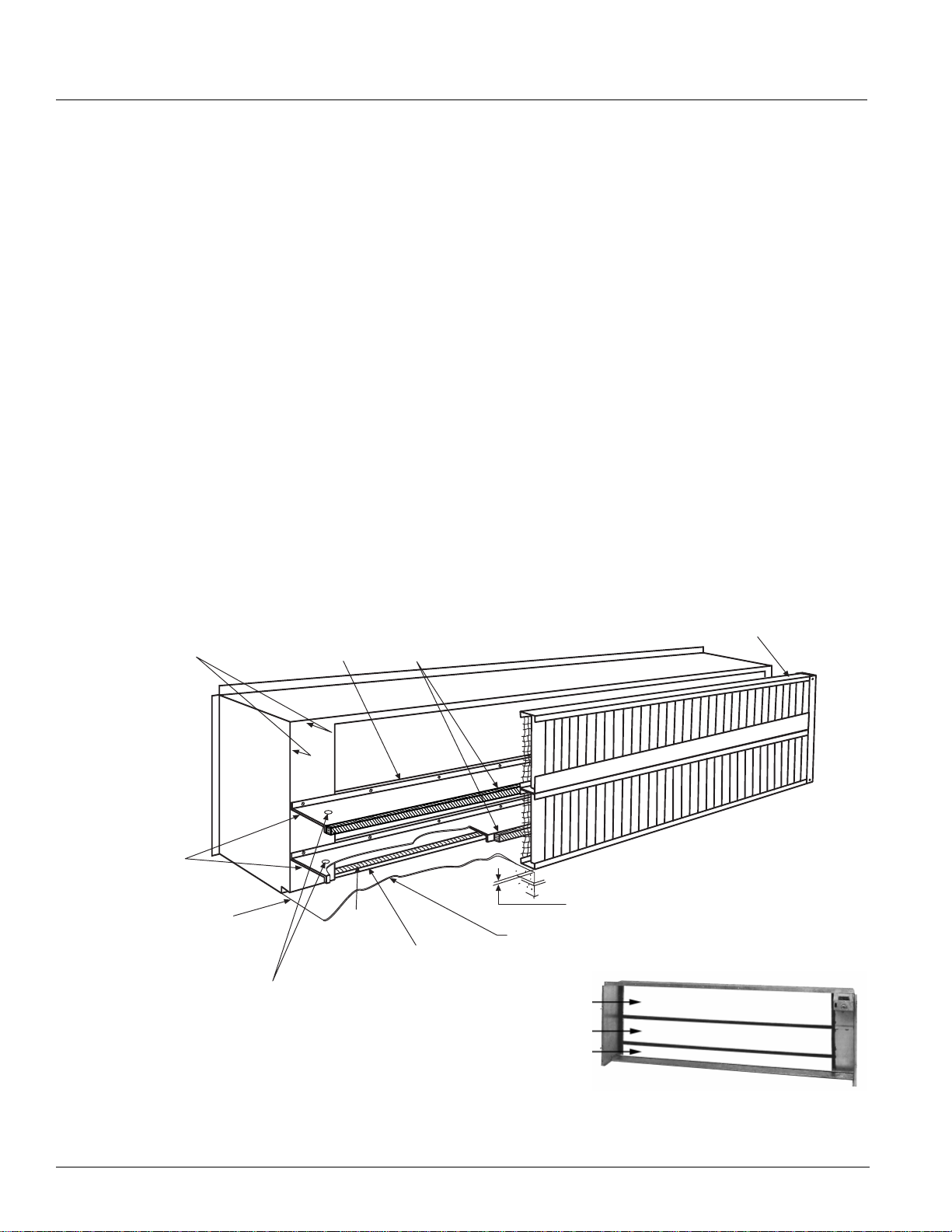
Application Considerations
Interior Considerations
The interior wall surface behind the unit ventilator must
be smooth and level. A wall that is slightly out of plumb
can cause major problems with outside air leakage into
the room and unit. This could cause draft s and potentially
freeze coils.
Be certain that no gap is left between the unit and th e
t
side air louver opening. Otherwise, outside air can
ou
leak into the room.
A rubberized, self-adhering membrane around the
u
tside air opening can be used to seal any air or water
o
leaks that might result from construction. Provide a seal
under the unit to prevent air infiltration. In addition, seal
the unit top and side perimeters to prevent unnecessary
air infiltration due to uneven walls.
Indoor Air Exhaust Considerations
All outdoor air introduced by the unit ventilator must
leave the room in some way. In some states, exhaust
Wall Sleeve Arrangements
vents are required by law. In states where vents are not
required by law, a decision must be made about how
best to handle this problem.
The venting system chosen should have the ability to
exhaust
varying amounts of air equal to the amount of
outside air introduced by the unit ventilator. A constant
volume system, such as a powered exhaust, is unable to
respond to changing conditions. It will either exhaust too
much air, resulting in a negative pressure, which draws
in more outdoor air than desired. Or, it will exhaust too
little air, resulting in increased positive pressure, which
restricts the amount of outside air being brought into the
room.
The AAF-HermanNelson Ventimatic shutter
eco
nomical solution to the problem. See “VentiMatic™
is a more
Shutter Room Exhaust Ventilation” on page 25 for
information on this system and its proper installation.
Figure 46.
By Others. Seal Horizontal
Air Splitters to building at
both ends.
IMPORTANT NOTE:
By Others: Attach Horizontal Air Splitters to Wall Sleeve
Splitters as shown. Splitters to have 1" dia. drain hole
approx. 6" from each end.
Recessed Wall Sleeve With Horizontal Air Splitters
By Others. Wall Sleeve must
be sealed watertight at top and
both ends at location shown.
By Others. Seal both ends of
opening between Wall Sleeve
and Louver.
Wall Sleeve Splitter(s)
(See Caution Above)
D Seal
By Others. Wall Sleeve must be sealed
watertight at bottom at location shown.
Refer to cross section detail of bottom
of Wall Sleeve and Louver.
Seal Horizontal Air Splitter(s)
to Louver. (By Others)
By Others. Louver must be sealed
watertight at top and both ends.
3
/16" Under Intake must be free for water run-off. Intake must
stand on embossed feet located on bottom.
By Others. Building must be sealed between Wall
Sleeve and under Louver for water run-off. Pitch
toward Louver.
Condenser discharge
Condenser inlet
Outdoor air inlet
40 McQuay Catalog 1620
Page 41

Application Considerations
Figure 47.
IMPORTANT NOTE :
By Others: Attach Horizontal Air
Splitters to Wall Sleeve Splitters as
shown. Splitters to have 1" dia. drain
hole approx. 6" from each end.
Figure 48.
By Others. Wall Sleeve must
be sealed watertight at top and
both ends at location shown.
Nonrecessed Wall Sleeve With Horizontal Air Splitters
Recessed Wall Sleeve Without Horizontal Air Splitters
IMPORTANT NOTE: By Others. Seal
Louver to Wall Sleeve at top and bottom Wall Sleeve Splitters, and ends.
By Others. Louver must be sealed
watertight at top and both ends.
Wall Sleeve Splitter(s)
D Seal
By Others. Seal Horizontal
Air Splitters to building at
both ends.
By Others. Wall Sleeve must be sealed
watertight at bottom at location shown.
Refer to cross section detail of bottom
of Wall Sleeve and Louver.
Figure 49.
Nonrecessed Wall Sleeve Without Horizontal Air Splitters
IMPORTANT NOTE: By Others. Seal
Louver to Wall Sleeve at top and bottom Wall Sleeve Splitters, and ends.
By Others. Wall Sleeve must
be sealed watertight at top and
both ends at location shown.
Wall Sleeve Splitter(s)
D Seal
By Others. Seal Horizontal
Air Splitters to building at
both ends.
By Others. Wall Sleeve must be sealed
watertight at bottom at location shown.
Refer to cross section detail of bottom
of Wall Sleeve and Louver.
3
/16" Under Intake must be free for water run-off. Intake must
stand on embossed feet located on bottom.
By Others. Building must be sealed between Wall
Sleeve and under Louver for water run-off. Pitch
toward Louver.
By Others. Louver must be sealed
watertight at top and both ends.
By Others. Building must be sealed between Wall
Sleeve and under Louver for water run-off. Pitch
toward Louver.
3
/16" Under Intake must be free for water run-off. Intake must
stand on embossed feet located on bottom.
AAF-HermanNelson Model AZ Unit Ventilators 41
Page 42

Unit Selection
Unit Selection
Quick Selection Procedure
The following procedure will provide you with a rough
Table 2: Hot Water Heating Capacity Btuh
determination of unit capacity for cooling and/or heating
based on the number of coil rows. Use capacity tables
for final selection. Consult your local AAF-HermanNelson
representative for details on the computer selection
programs McQuay International provides for this purpose
Table 3: Standard Cooling at High Indoor Fan Speed
Conditions; Indoor 80ºDB / 67ºWB, Outdoor 95ºDB / 75ºWB
Nominal Airflow High Indoor
fan speed
Unit Size L/S Btuh Watts Btuh Watts EER Watts
024 472 22,100 6,478 15,500 4,543 9.7 2,276
036 590 36,800 10,786 23,800 6,976 9.5 3,888
044 708 44,000 12,896 31,500 9,233 9.4 4,700
054 708 52,100 15,271 35,500 10,405 9.3 5,600
Table 4: Partial Load Cooling at Medium Indoor Fan Speed
Nominal Airflow Medium
Indoor fan speed
Unit Size L/S Btuh Watt s Btuh Watts EER Watts
024 354 18,000 5,276 12,200 3,576 12.6 1,423
036 472 28,000 8,207 19,000 5,569 12.4 2,259
044 542 36,300 10,640 24,900 7,298 11.8 3,060
054 542 42,700 12,515 27,500 8,060 11.8 3,600
Total Cooling Capacity Sensible Cooling Capacity Efficiency Power
Conditions; Indoor 80ºDB / 67ºWB, Outdoor 82ºDB / 65ºWB
Total Cooling Capacity Sensible Cooling Capacity Efficiency Power
Rows 024 036 044, 054
1 49,500 57,000 66,000
2 62,000 74,100 97,200
3 72,000 84,500 97,500
4 81,000 95,000 110,000
60°F Entering Air Temperature; 160°F Entering
Water Temperature;
6 Gpm Water Flow
42 McQuay Catalog 1620
Page 43

Unit Selection
Selection Procedure
Step 1: Determine Design Conditions
Determine design indoor and outdoor a ir temperatur es in
accordance with established engineering practices, as
outlined in the ASHRAE Guide or other authoritative
source. Indoor temperatures of 80°F dry bulb, 67°F wet
bulb for summer and 70°F dry bulb for winter usually are
acceptable for design or peak load conditions, even
though the expected operating conditions of the system
may be somewhat different.
Step 2: Determine Heating and Cooling Loads
Calculate design winter heating losses and summer
cooling loads in accordance with the procedures outlined
by the ASHRAE Guide or other authoritative source.
Perhaps the greatest consideration in calculating design
loads is solar heat gain. August solar heat values might
be used for summer cooling loads, but should not be
used for ventilation air or “natural cooling” capacity
calculations; since these cooling loads reach their
maximum in the spring and autumn months. The na tu ra l
cooling capacity is usually calculated for 55° or 60°F
outdoor air temperature.
Step 3: Determine Air Quantity Required
Air quantity for heating applications is determined from
circulation of a definite number of room air volumes per
hour. Table 5 gives the recommended number of room
air changes per hour.
Table 5: Recommende d Ro om Air Changes Per Hour
Type of Space
Classrooms, Offices 6 to 9
Laboratories, Shops 6 to 8
Cafeterias & Kitchens 4-1/2 to 7
For rooms facing east, south or west, the higher values
shown in the table should be used so adequate
ventilation cooling will be available to prevent
overheating during mild sunny weather. The following
equation is helpful to determine the CFM air delivery for
any given rate of circulation:
Equation 6: CFM For Given Rate Of Circulation
Room Volume (cu ft) Room Changes per Hour×
------------------------------------------------------------------------------------------------------------------- - CFM=
In mechanical cooling applications, the total air quantity
may be determined or verified by use of the sensib le
cooling load equation:
Recommended number of
room air changes per Hour
60
Equation 7: CFM Based On Sensible Cooling Load
CFM
Q sensible (space)
------------------------------------------- -=
1.086xTD
Q sensible is the maximum sensible room load and T.D.
is the temperature difference between the room design
dry bulb temperature and the final or leaving-air dry bulb
temperature. For these calculations, a T.D. of 20°F is
usually assumed to be desirable to avoid delivering air
too cold for comfort. This figure may be varied o ne or two
degrees for reasons of practicality.
Note: The sensible load used in the preceding equation is the
space load and excludes the ventilation load.
Most areas have ventilation codes which govern the
amount of ventilation air required for scho ol a pplica tio ns.
For other than school applications or areas not having
codes, the ASHRAE Guide may be used for authoritative
recommendations and discussion of the relation between
odor control and outdoor air quantities.
The minimum outdoor air quantity recommended by
ASHRAE is 15 CFM per
person. L
ower percent minimum
outdoor air settings are more economical. In the interest
of economy, it may be desirable to use lower percent
minimums if there are no ventilation codes.
Step 4: Select Unit Size
The unit should be selected to meet or exceed the CFM
delivery requirement previously determined. All model
types are available with nominal capacities of 1000, 1 250
and 1500 CFM. Unit sizes 024, 036, 044, and 054.
Heating Capacity
Unit heating capacity should be selected to equal or
slightly exceed the computed room heat loss. For units
installed for 100% recirculation, it is good practice to
increase the heating capacity by 15% to aid in quick
room warm-up. This allowance is unnecessary for units
delivering a minimum outdoor air of 20% or more, since
the outdoor air damper remains closed until the room is
up to temperature. The heat normally expended in
heating the minimum-percent outdoor air up to room
temperature is available for quick warm-up purposes.
The heating required to warm the outdoor ventilating air up
to room temperature must also be calculated. The Total
Capacity should be used in sizing, piping, boilers, etc.
Cooling Capacity
Unit cooling capacity should be selected to equal or
slightly exceed the sum of computed room sensible and
AAF-HermanNelson Model AZ Unit Ventilators 43
Page 44

Unit Selection
latent heat gains (Room Total Cap acity). When operatin g
on the mechanical cooling cycle, the control system
introduces a constant amount of outdoor air for
ventilation. The latent and sensible heat gain from this
outdoor ventilation air must be added to the room total
cooling load before choosing the proper capacity unit.
Step 5: Freeze Protection
Constant pump operation is required whenever the
outdoor air temperature is below 35°F. This will assist
in providing protection against freeze up of the system
water piping and coils. To reduce the possibility of water
coil freeze up on valve-controlled units, the valve must
be selected properly to provide adequate wate r flow. See
“Modulating Valve Sizing & Piping” on page 51. One of
the steps below should be followed.
Hot Water
Carry out one of the following steps to help protect
against freezing:
• Use antifreeze in the system.
• Open the hot water coil valve and close the outdoor air
mper whenever a freezing condition is sensed at the
da
coil.
Step 6: Units With Antifreeze
If ethylene glycol or propylene glycol is used, its effect
upon heating capacities and its effect on water pressure
drops through the coil and piping system must be
considered, as follows:
1 Divide the
applicable capacity correction factor shown in Tables
heating loads determined in S te p 2 by the
6 and 7 below to arrive at the calculated unit capacity
required to take care of the capacity reduction caused
by the glycol solution
Table 6: Capacity Correction Fa c tors for Ethylene Glycol
Ethylene Glycol% Weight 20% 30% 40%
Hot Water 0.94 0.90 0.84
Table 7: Capacity Correction Factors for Propylene Glycol
Propylene Glycol% Weight 20% 30% 40%
Hot Water 0.98 0.96 0.92
.
2 Determine the GPM required by entering the
appropriate hot water capacity chart using the
calculated unit capacity.
3 Determine the water pressure drop by multiplying the
pressure drop for the GPM determined above
water
by the applicable pressure drop correction factor
shown in Tables 8 and 9 below
Table 8: Pressure Drop Correction Factors For Ethylene
Glycol
Ethylene Glycol% Weight 20% 30% 40%
Hot Water 1.08 1.11 1.19
Table 9: Pressure Drop Correction Factors For Propylene
Glycol
Propylene Glycol% Weight 20% 30% 40%
Hot Water 1.07 1.11 1.15
.
44 McQuay Catalog 1620
Page 45

Unit Selection
T
Hot Water Heating Selection
For proper temperature control, do not oversize the
heating coil. Select the hot water coil that just slightly
exceeds the required heating capacity. Hot water coils
are offered in two capacities. The low-capacity (65) coil
and the high-capacity (66) coil can be used as heating
only or in conjunction with direct-expansion cooling coil.
Quick Selection Method Using MBH/∆T
Once the unit size has been selected, the MBH/∆T factor
can be utilized to quickly and accurately determine coil
size and minimum GPM, where:
ntering Water Temp - Entering Air Temp
∆T = E
Fo
r example, assume an entering water temperature of
F, an entering air temperature of 55°F and a total
180°
heating load of 75 MBH. Then,
Figure 50. 1-Row Hot Water Coil
0.8
0.7
0.6
MBH/d
0.5
044, 054
1500SCFM
= 180 - 55 = 125
∆T
an
d,
MBH/∆T = 75/1
25 = 0.6
Assume we want to size for the 036 unit determined in
coil selection example previously given for cooling.
the
Referring to Figures 50 and 51:
1 Enter each chart at MBH/∆T
= 0.6.
2 Move horizontally to the right to intersect the unit 036,
12
50 scfm curve.
3 Project downward for
GPM requirement.
It is quickly seen that the 1-row coil (Figure 50) does not
meet the heating load. The 2-row coil (Figure 51) can
meet the requirement with 3.4 GPM.
036
1250SCFM
024
1000SCFM
0.4
0.3
2345678910
Figure 51. 2-Row Hot Water Coil (Parallel Flow)
1.1
1
0.9
0.8
MBH/dT
0.7
0.6
0.5
0.4
234567 8910
044, 054
1500 SC FM
GPM
GPM
036
1250 SC FM
024
1000 SC FM
AAF-HermanNelson Model AZ Unit Ventilators 45
Page 46

Unit Selection
Steam Heating Selection
The maximum allowable steam pressure, especially in
public buildings, is often fixed by state or local boiler
codes. Steam Capacity in Table 10 is based on steam
supply pressure of 2 PSI gauge and steam temperature
f
218.5°F.
o
To determine total capacity for
conditions other than
capacity given by the proper constant from the Steam
city Correction Factor in Table 11.
Capa
Maximum steam pressure is 6
PSIG at coil inlet.
Traps are by others. Either float an d thermostatic tr aps or
thermo
static traps may be used.
shown in the Steam Capacity Table 10, multiply the total
LAT, db
1
Entering Air Temperature °F
MBH
LAT, db
MBH
LAT, db
MBH
LAT, db
MBH
LAT, db
MBH
LAT, db
MBH
Table 10: Steam Heating Capacities - 2# Steam Coils
-20 -10 0 10 20 30 40 50 60 70
Unit
Airflow SCFM
MBH
Coil Capacity
Std 1000 82.1 55.8 78.7 62.6 75.2 69.3 71.6 76.0 68.0 82.7 65.6 90.5 61.8 97.0 58.0 103.5 54.1 109.9 50.4 116.5
024
High 1000 98.3 70.6 94.1 76.8 89.9 82.9 85.6 89.0 81.3 95.0 77.0 101.0 72.3 106.7 67.7 112.4 63.0 118.1 58.4 123.9
Std 1250 97.0 51.6 93.0 58.6 89.0 65.7 85.0 72.7 80.9 79.7 76.7 86.6 72.3 93.3 67.9 100.1 63.5 106.9 59.9 114.2
036
High 1250 122.6 70.4 117.6 76.7 1 12.5 83.0 107.3 89.2 102.1 95.3 96.8 101.4 91.2 107.3 85.6 113.2 80.0 119.0 74.4 124.9
Std 1500 121.3 54.6 116.5 61.6 111.5 68.5 106.5 75.5 101.4 82.3 96.3 89.2 90.8 95.8 85.5 102.5 80.0 109.2 75.6 116.5
044
054
High 1500 140.0 66.0 134.3 72.5 128.5 79.0 123.6 86.0 117.7 92.4 111.8 98.7 105.5 104.8 99.2 111.0 92.8 117.1 86.6 123.2
1.
Data based on 2psig steam pressure @10°F superheat steam vapor.
LAT, db
MBH
LAT, db
MBH
Table 11: Steam Capacity Correction Factors
Steam Pressure
PSIG
0 0.97 0.97 0.97 0.96 0.97 0.97 0.97 0.96 0.96 0.96
2 1.00 1.00 1.00 1.00 1.00 1.00 1.00 1.00 1.00 1.00
5 1.02 1.03 1.03 1.03 1.04 1.05 1.05 1.05 1.05 1.05
-20 -10 0 10 20 30 40 50 60 70
Entering Air Temperature Mixture, °F
LAT, db
MBH
LAT, db
Engineering Data
Table 12: Electrical Data – Size 024 Models AZQ and AZU
Voltage
208/60/1
230/60/1
208/60/3
230/60/3
460/60/3
† Electric heat options are without compressor and outdoor fan
FLA = Full Load Amps RLA = Rated Load Amps LRA = Locked Rotor Amps MCA = Minimum Circuit Ampacity
Vol tage Range Room Fan
Min Max RLA LRA Heat Type Heater kW Heater Amps MCA Maximum Fuse
197 228 2.7 2.9 11.4 52.0
207 253 2.7 2.9 11.4 52.0
197 228 2.7 2.9 7.9 59.0
207 253 2.7 2.9 7.9 59.0
414 506 2.7 1.2 3.9 29.7
46 McQuay Catalog 1620
FLA
Outdoor Fan
FLA
Compressor Heating Options Power Supply
None, Hot Water, Steam -- -- 19.9 30
†Electric Heat
None, Hot Water, Steam -- -- 19.9 30
†Electric Heat
None, Hot Water, Steam -- -- 15.5 20
†Electric Heat
None, Hot Water, Steam -- -- 15.5 20
†Electric Heat
None, Hot Water, Steam -- -- 8.8 15
†Electric Heat
Low (3-elem.) 8.0 38.5 51.5 60
High (6-elem.) 16.0 76.9 99.5 100
Low (3-elem.) 7.7 33.3 45.0 45
High (6-elem.) 15.3 66.7 86.7 90
Low (3-elem.) 8.0 22.2 31.1 35
High (6-elem.) 16.0 44.4 58.9 60
Low (3-elem.) 7.7 19.2 27.4 30
High (6-elem.) 15.3 38.5 51.5 50
Low (3-elem.) 7.7 9.6 15.4 20
High (6-elem.) 15.3 19.2 27.4 25
Page 47

Unit Selection
Table 13: Electrical Data – Size 036 Models AZQ and AZU
Voltage
208/60/1
230/60/1
208/60/3
230/60/3
460/60/3
Vol tage Range Room Fan
Min Max RLA LRA Heat Type Heater kW Heater Amps MCA Maximum Fuse
197 228 2.7 2.9 18.6 96.0
207 253 2.7 2.9 18.6 96.0
197 228 2.7 2.9 15.0 88.0
207 253 2.7 2.9 15.0 88.0
414 506 2.7 1.2 6.8 44.0
† Electric heat options are without compressor and outdoor fan
FLA = Full Load Amps RLA = Rated Load Amps LRA = Locked Rotor Amps MCA = Minimum Circuit Ampacity
Table 14: Electrical Data – Size 044 Models AZQ and AZU
Voltage
208/60/1
230/60/1
208/60/3
230/60/3
460/60/3
† Electric heat options are without compressor and outdoor fan
FLA = Full Load Amps RLA = Rated Load Amps LRA = Locked Rotor Amps MCA = Minimum Circuit Ampacity
Vol tage Range Room Fan
Min Max RLA LRA Heat Type Heater kW Heater Amps MCA Maximum Fuse
197 228 2.7 6.8 23.6 96.0
207 253 2.7 6.8 23.6 96.0
197 228 2.7 6.8 15.0 88.0
207 253 2.7 6.8 15.0 88.0
414 506 2.7 2.2 7.1 41.0
FLA
FLA
Outdoor Fan
FLA
Outdoor Fan
FLA
Compressor Heating Options Power Supply
None, Hot Water, Steam -- -- 28.9 45
†Electric Heat
None, Hot Water, Steam -- -- 28.9 45
†Electric Heat
None, Hot Water, Steam -- -- 24.4 35
†Electric Heat
None, Hot Water, Steam -- -- 24.4 35
†Electric Heat
None, Hot Water, Steam -- -- 12.4 15
†Electric Heat
Compressor Heating Options Power Supply
None, Hot Water, Steam -- -- 39.0 60
†Electric Heat
None, Hot Water, Steam -- -- 39.0 60
†Electric Heat
None, Hot Water, Steam -- -- 28.3 40
†Electric Heat
None, Hot Water, Steam -- -- 28.3 40
†Electric Heat
None, Hot Water, Steam -- -- 13.8 20
†Electric Heat
Low (3-elem.) 10.0 48.1 63.5 70
High (6-elem.) 20.0 96.2 123.6 125
Low (3-elem.) 9.6 41.7 55.5 60
High (6-elem.) 19.2 83.3 107.5 110
Low (3-elem.) 10.0 27.8 38.1 40
High (6-elem.) 20.0 55.5 72.8 80
Low (3-elem.) 9.6 24.1 33.4 45
High (6-elem.) 19.2 48.1 63.5 70
Low (3-elem.) 9.6 12.0 18.4 20
High (6-elem.) 19.2 24.1 33.4 35
Low (3-elem.) 12.0 57.7 75.5 80
High (6-elem.) 24.0 115.4 147.6 150
Low (3-elem.) 11.5 50.0 65.9 70
High (6-elem.) 23.0 100.0 128.4 125
Low (3-elem.) 12.0 33.3 45.0 45
High (6-elem.) 24.0 66.6 86.6 90
Low (3-elem.) 11.5 28.9 39.5 40
High (6-elem.) 23.0 57.7 75.5 80
Low (3-elem.) 11.5 14.4 21.4 25
High (6-elem.) 23.0 28.9 39.5 40
Table 15: Electrical Data – Size 054 Models AZQ and AZU
Voltage
208/60/1
230/60/1
208/60/3
230/60/3
460/60/3
Vol tage Range Room Fan
Min Max RLA LRA Heat Type Heater kW Heater Amps MCA Maximum Fuse
197 228 2.7 6.8 28.6 118.0
207 253 2.7 6.8 28.6 118.0
197 228 2.7 6.8 19.6 123.0
207 253 2.7 6.8 19.6 123.0
414 506 2.7 2.2 10.0 62.0
† Electric heat options are without compressor and outdoor fan
FLA = Full Load Amps RLA = Rated Load Amps LRA = Locked Rotor Amps MCA = Minimum Circuit Ampacity
FLA
Outdoor Fan
FLA
Compressor Heating Options Power Supply
None, Hot Water, Steam -- -- 45.3 70
†Electric Heat
None, Hot Water, Steam -- -- 45.3 70
†Electric Heat
None, Hot Water, Steam -- -- 34.0 50
†Electric Heat
None, Hot Water, Steam -- -- 34.0 50
†Electric Heat
None, Hot Water, Steam -- -- 17.4 25
†Electric Heat
Low (3-elem.) 12.0 57.7 75.5 80
High (6-elem.) 24.0 115.4 147.6 150
Low (3-elem.) 11.5 50.0 65.9 70
High (6-elem.) 23.0 100.0 128.4 125
Low (3-elem.) 12.0 33.3 45.0 50
High (6-elem.) 24.0 66.6 86.6 90
Low (3-elem.) 11.5 28.9 39.5 50
High (6-elem.) 23.0 57.7 75.5 80
Low (3-elem.) 11.5 14.4 21.4 25
High (6-elem.) 23.0 28.9 39.5 40
AAF-HermanNelson Model AZ Unit Ventilators 47
Page 48

Unit Selection
Table 16: Electrical Data – Size 024 Model AZR
Voltage
208/60/1
230/60/1
208/60/3
230/60/3
460/60/3
Vol tage Range Room Fan
Min Max RLA LRA Heat Type Heater kW Heater Amps MCA Maximum Fuse
197 228 2.7 2.9 11.4 52.0
207 253 2.7 2.9 11.4 52.0
197 228 2.7 2.9 7.9 59.0
207 253 2.7 2.9 7.9 59.0
414 506 2.7 1.2 3.9 29.7
† Electric heat options are with compressor and outdoor fan
FLA = Full Load Amps RLA = Rated Load Amps LRA = Locked Rotor Amps MCA = Minimum Circuit Ampacity
Table 17: Electrical Data – Size 036 Model AZR
Voltage
208/60/1
230/60/1
208/60/3
230/60/3
460/60/3
† Electric heat options are with compressor and outdoor fan
FLA = Full Load Amps RLA = Rated Load Amps LRA = Locked Rotor Amps MCA = Minimum Circuit Ampacity
Vol tage Range Room Fan
Min Max RLA LRA Heat Type Heater kW Heater Amps MCA Maximum Fuse
197 228 2.7 2.9 18.6 96.0
207 253 2.7 2.9 18.6 96.0
197 228 2.7 2.9 15.0 88.0
207 253 2.7 2.9 15.0 88.0
414 506 2.7 1.2 6.8 44.0
FLA
FLA
Outdoor Fan
FLA
Outdoor Fan
FLA
Compressor Heating Options Power Supply
None, Hot Water, Steam -- -- 19.9 30
†Electric Heat
None, Hot Water, Steam -- -- 19.9 30
†Electric Heat
None, Hot Water, Steam -- -- 15.5 20
†Electric Heat
None, Hot Water, Steam -- -- 15.5 20
†Electric Heat
None, Hot Water, Steam -- -- 8.8 15
†Electric Heat
Compressor Heating Options Power Supply
None, Hot Water, Steam -- -- 28.9 45
†Electric Heat
None, Hot Water, Steam -- -- 28.9 45
†Electric Heat
None, Hot Water, Steam -- -- 24.4 35
†Electric Heat
None, Hot Water, Steam -- -- 24.4 35
†Electric Heat
None, Hot Water, Steam -- -- 12.4 15
†Electric Heat
Low (3-elem.) 8.0 38.5 67.9 70
High (6-elem.) 16.0 76.9 116.0 125
Low (3-elem.) 7.7 33.3 61.5 70
High (6-elem.) 15.3 66.7 103.2 110
Low (3-elem.) 8.0 22.2 43.2 45
High (6-elem.) 16.0 44.4 71.0 80
Low (3-elem.) 7.7 19.2 39.5 40
High (6-elem.) 15.3 38.5 63.6 70
Low (3-elem.) 7.7 9.6 20.8 20
High (6-elem.) 15.3 19.2 32.8 35
Low (3-elem.) 10.0 48.1 88.9 90
High (6-elem.) 20.0 96.2 149.0 150
Low (3-elem.) 9.6 41.7 80.9 90
High (6-elem.) 19.2 83.3 133.0 150
Low (3-elem.) 10.0 27.8 59.0 60
High (6-elem.) 20.0 55.5 93.7 100
Low (3-elem.) 9.6 24.1 54.4 60
High (6-elem.) 19.2 48.1 84.5 90
Low (3-elem.) 9.6 12.0 27.4 30
High (6-elem.) 19.2 24.1 42.5 45
Table 18: Electrical Data – Size 044 Model AZR
Voltage
208/60/1
230/60/1
208/60/3
230/60/3
460/60/3
Vol tage Range Room Fan
Min Max RLA LRA Heat Type Heater kW Heater Amps MCA Maximum Fuse
197 228 2.7 6.8 23.6 96.0
207 253 2.7 6.8 23.6 96.0
197 228 2.7 6.8 15.0 88.0
207 253 2.7 6.8 15.0 88.0
414 506 2.7 2.2 7.1 41.0
† Electric heat options are with compressor and outdoor fan
FLA = Full Load Amps RLA = Rated Load Amps LRA = Locked Rotor Amps MCA = Minimum Circuit Ampacity
FLA
Outdoor Fan
FLA
Compressor Heating Options Power Supply
None, Hot Water, Steam -- -- 39.0 60
†Electric Heat
None, Hot Water, Steam -- -- 39.0 60
†Electric Heat
None, Hot Water, Steam -- -- 28.3 40
†Electric Heat
None, Hot Water, Steam -- -- 28.3 40
†Electric Heat
None, Hot Water, Steam -- -- 13.8 20
†Electric Heat
Low (3-elem.) 12.0 57.7 111.1 125
High (6-elem.) 24.0 115.4 183.2 200
Low (3-elem.) 11.5 50.0 101.5 110
High (6-elem.) 23.0 100.0 164.0 175
Low (3-elem.) 12.0 33.3 69.9 70
High (6-elem.) 24.0 66.6 1 11.5 110
Low (3-elem.) 11.5 28.9 64.3 70
High (6-elem.) 23.0 57.7 100.4 100
Low (3-elem.) 11.5 14.4 31.8 35
High (6-elem.) 23.0 28.9 49.9 50
48 McQuay Catalog 1620
Page 49
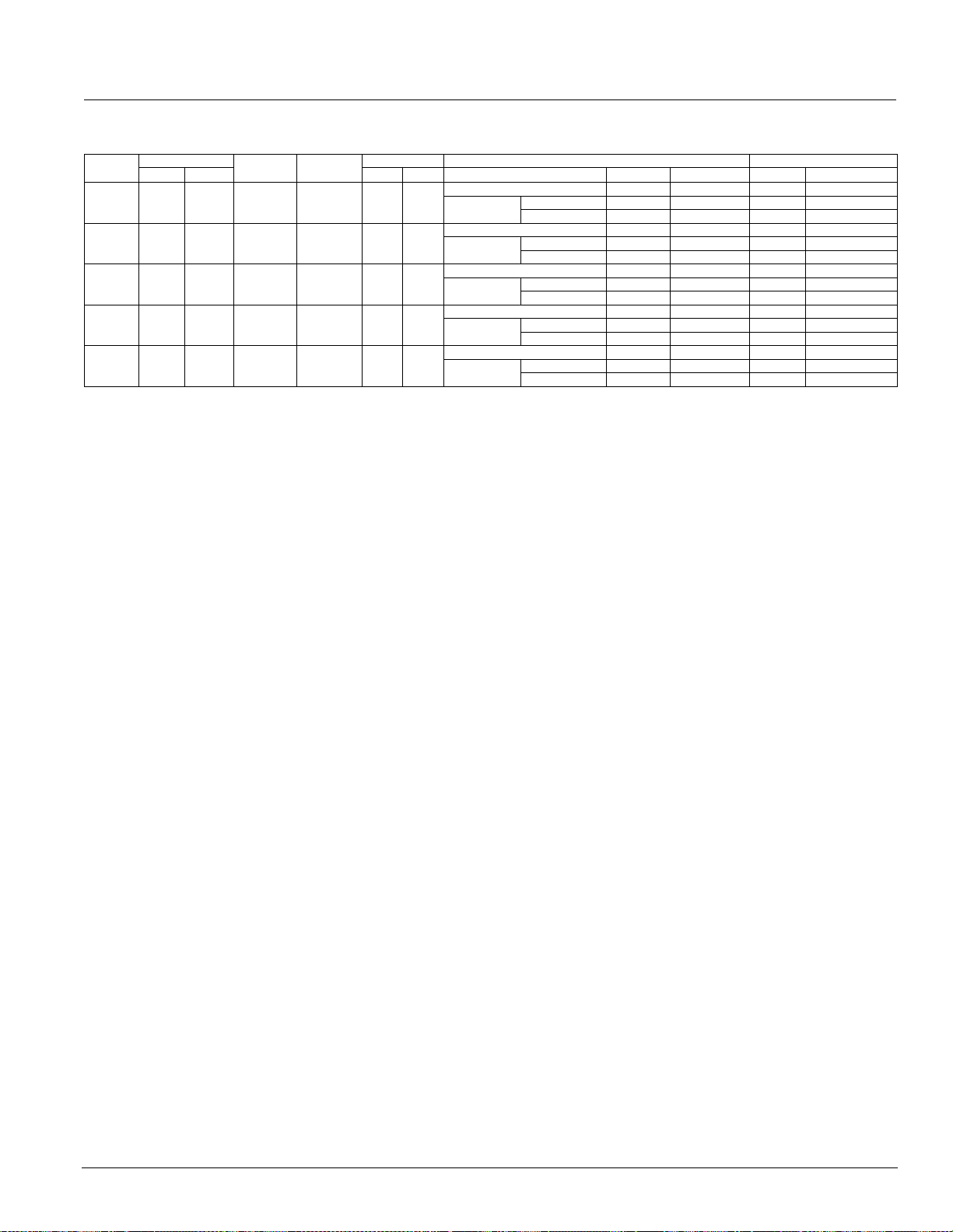
Unit Selection
Table 19: Electrical Data – Size 054 Model AZR
Voltage
208/60/1
230/60/1
208/60/3
230/60/3
460/60/3
Vol tage Range Room Fan
Min Max RLA LRA Heat Type Heater kW Heater Amps MCA Maximum Fuse
197 228 2.7 6.8 28.6 118.0
207 253 2.7 6.8 28.6 118.0
197 228 2.7 6.8 19.6 123.0
207 253 2.7 6.8 19.6 123.0
414 506 2.7 2.2 10.0 62.0
† Electric heat options are with compressor and outdoor fan
FLA = Full Load Amps RLA = Rated Load Amps LRA = Locked Rotor Amps MCA = Minimum Circuit Ampacity
FLA
Outdoor Fan
FLA
Compressor Heating Options Power Supply
None, Hot Water, Steam -- -- 45.3 70
†Electric Heat
None, Hot Water, Steam -- -- 45.3 70
†Electric Heat
None, Hot Water, Steam -- -- 34.0 50
†Electric Heat
None, Hot Water, Steam -- -- 34.0 50
†Electric Heat
None, Hot Water, Steam -- -- 17.4 25
†Electric Heat
Low (3-elem.) 12.0 57.7 117.4 125
High (6-elem.) 24.0 115.4 189.5 200
Low (3-elem.) 11.5 50.0 107.8 110
High (6-elem.) 23.0 100.0 170.3 175
Low (3-elem.) 12.0 33.3 75.6 80
High (6-elem.) 24.0 66.6 117.3 125
Low (3-elem.) 11.5 28.9 70.1 80
High (6-elem.) 23.0 57.7 106.2 110
Low (3-elem.) 11.5 14.4 35.4 40
High (6-elem.) 23.0 28.9 53.5 60
AAF-HermanNelson Model AZ Unit Ventilators 49
Page 50
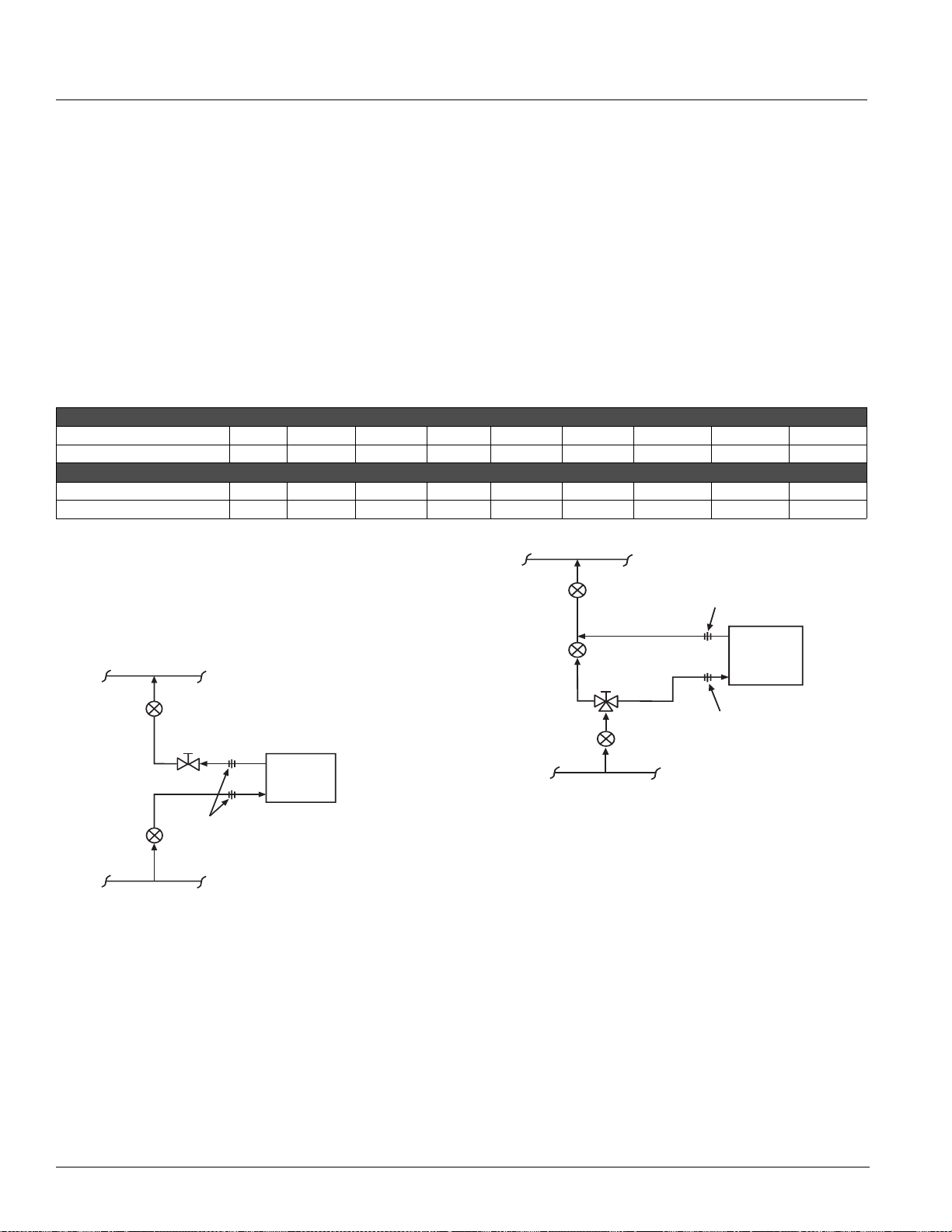
Valve Selection
Valve Selection
Face and Bypass End-Of-Cycle Valve Sizing & Piping
Note: Piping packages can be purchased from McQuay or
provided by others
MicroTech II face and bypass damper control requires an
end-of-cycle (EOC) valve for each hydronic coil. End-ofcycle (or two position) valves are either full-open or fullclosed. To select an end-of-cycle valve:
1 Determine the flow of water and the correspond ing
pressure drop through the coil.
2 Obtain the pressure difference between the supply
and return mains.
3 Select a valve (Cv) on the basis of taking 10% of the
available pressure difference (at design flow) between
the supply and return mains at the valve location. The
valve should have a pressure drop less than or equal
to that of the coil.
Table 20 gives the pressure drops at various water flow
rates for the Cv of the valve listed. EOC valves for water
applications can be either two-way or three-way.
Refer to the EOC valve label to determine the direction of
flow. The EOC valve must be installed on the unit for
which it was selected.
Table 20: Hot Water End-Of-Cycle Valve Selection By Pressu re Drop
2-Way Hot Water EOC Valve (7.0 Cv), FNPT, Normally Open
Water Flow GPM (L/s)
Water Pres. Drop Ft-H2O (kPa)
Water Flow GPM (L/s)
Water Pres. Drop Ft-H2O (kPa)
7 (0.44) 9.9 (0.62) 12.1 (0.76) 14 (0.88) 15.7 (0.99) 22.1 (1.39) 27.1 (1.71) 31.3 (1.98) 35.0 (2.20)
2.3 (6.9) 4.6 (13.8) 6.9 (20.7) 9.2 (27.6) 11.6 (34.5) 23.1 (69.0) 34.7 (103.4) 46.2 (138.0) 57.8 (172.4)
3-Way Hot Water EOC Valve (5.0 Cv), FNPT, Normally Open
5 (0.32) 7.1 (0.45) 8.7 (0.55) 10 (0.63) 11.2 (0.71) 15.8 (1.00) 19.4 (1.22) 22.3 (1.41) 25.0 (1.58)
2.3 (6.9) 4.6 (13.8) 6.9 (20.7) 9.2 (27.6) 11.6 (34.5) 23.1 (69.0) 34.7 (103.4) 46.2 (138.0) 57.8(172.4)
Hot Water EOC Valve Piping
Hot water EOC valves are furnished normally open to the
coil. When the valve is de-energized (off) there is fu ll flow
through the coil. Energizing the valve shuts off the water
flow.
Figure 52. 2-Way Hot Water EOC Valve Piping
Return
Balancing & Shutoff Valve
Shutoff Valve
Supply
2-way
EOC Valve
A
B
Unions
Unit Coil
Return
Supply
Figure 53. 3-Way Hot Water EOC Valve Piping
Return
Balancing &
(Bypass)
Supply
Shutoff Valve
Balancing Valve
3-way
EOC Valve
B
A
AB
Shutoff Valve
Union
Unit Coil
Return
Supply
Union
50 McQuay Catalog 1620
Page 51
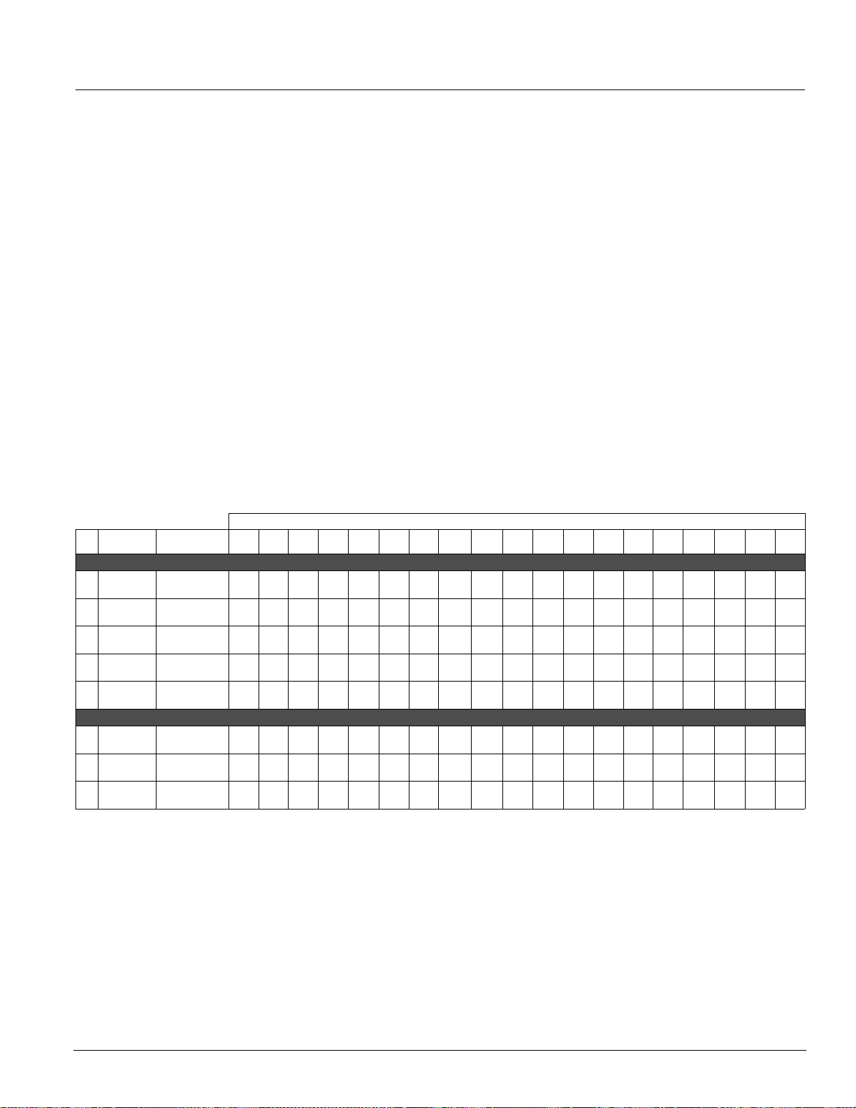
Valve Selection
Modulating Valve Sizing & Piping
Note: Piping packages can be purchased from McQuay or
provided by others
The unit ventilator control valve is expected to vary the
quantity of water that flows through the coil in a
modulating fashion. Any movement of the valve stem
should produce some change in the amount of water that
flows through the coil. Oversized control valves cannot
do this.
For example, assume that, when the control valve is fully
open, the pressure drop through the coil is twice as great
as the drop through the valve. In this case, the control
valve must travel to approximately 50% closed before it
can begin to have any influence on the water flow
through the coil. The control system, no matter how
sophisticated, cannot overcome this. Oversized control
valves can also result in hunting which will shorten the
life of the valve and actuator and possibly damage the
coil.
To correctly select the modulating valve:
Table 21: Hot Water M od ulating Valve Selection By Flow Rate
Valve Pressure Drop [ft of H2O (kPa)] at Listed Water Flow Rate [GPM (L/s)]
Cv Connection
1.3
1/2 inch
2.2
1/2 inch
4.4
1/2 inch
6.6
3/4 inch
7.5
3/4 inch
2.0
1/2 inch
4.0
1/2 inch
6.0
3/4 inch
Recommended
Flow Rates2 (.13)3(.19)4 (.25)5(.32)6 (.38)7(.44)8 (.51)9 (.57)
Hot Water 2-Way Modulating Valve, Normally Open
2 - 5 GPM
.13 -.32 L/s
5 - 8.5 GPM
.32 -.54L/s
8.5 -12.3 GPM
.54 -.78 L/s
2-5 GPM
.78 - 1.1 L/s
Over 16.8 GPM
Over 1.1 L/s
5.5
12.3
21.8
34.1
(16.6)
(36.6)
(65.5)
––
––––––
–––––––– ––
–––––––– ––––––
7.5
(22.8)
–––––––––––––––
(102)
11.9
17.4
23.4
(35.9)
(51.0)
(69.7)
30.5
(91.0)
10.2
(30.3)
Hot Water 3-Way Modulating Valve, Normally Open
2 - 8 GPM
.13 -.51 L/s
8 - 14 GPM
.51 -.88 L/s
Over 14 GPM
Over.88 L/s
2.3
5.2
9.2
14.4
20.8
28.3
(6.9)
(15.9)
(27.6)
(43.5)
(62.1)
–––––––
–––––––– ––––
(84.8)
36.9
(110)
1 Determine the flow of water and the corresponding
pressure drop through the coil.
2 Obtain the pressure difference between the supply
and return mains.
3 Select a valve (Cv) from Table 21 on the basis of
taking 50% of the available pressure difference (at
design flow) between the supply and return mains at
the valve location. The valve should have a pressure
drop greater than that of the coil. Whenever possible
there should be at least 11 feet of water (5psi) (32.9
kPa) pressure drop across the valve.
Modulating valves for water applications can be either
2-way or 3-way. Refer to the modulating valve label to
determine the direction of flow. The modulating valve
must be installed on the unit for which it was selected.
The modulating valve furnished for steam applications is
a 2-way, normally open to the coil configuration (see
“Modulating Steam Valve Selection” on page 52 for
application).
10
(.63) 11(.64)12(.76)
38.6
–––––––––––
(115.2)
12.9
16.0
(47.6)
14.4
(43.5)
19.3
(57.9)
17.4
(52.4)
(38.6)
––––––––––––
11.7
(35.2)
(.82)14(.88)15(.95)
23.0
27.0
(69.0)
(80.7)
11.0
12.9
(69.0)
(80.7)
20.8
24.4
(62.1)
(73.1)
13
–––– –––
15.0
(44.8)
28.3
(84.8)
9.7
(29.0)
16
17
(1.0)
17.2
19.5
(51.0)
(58.6)
10.5
(31.5
––– –––
11.2
12.8
(33.8)
(37.9)
18
(1.0)
(1.1)
22.0
–––
(66.2)
11.9
13.3
(35.7)
(40.0)
14.4
16.2
(43.5)
(48.3)
(44.1)
(53.8)
19
(1.2)
14.8
18.0
20
(1.3)
16.4
(49.0)
20.0
(60.0)
AAF-HermanNelson Model AZ Unit Ventilators 51
Page 52
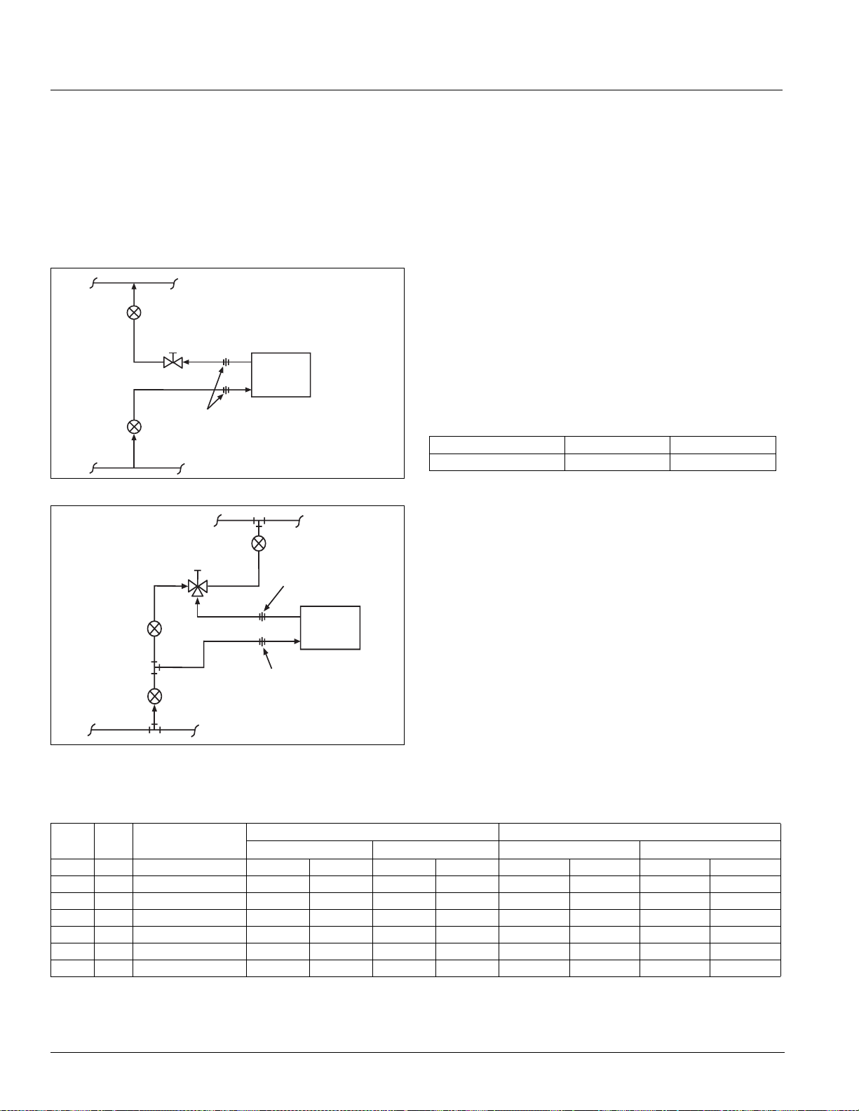
Valve Selection
Hot Water Modulating Valve Piping
Note: Piping packages can be purchased from McQuay or
provided by others
Modulating hot water valves are furnished normally open
to the coil. When the valve is de-energized (off) there is
full flow through the coil. Energizing the valve allows a
varying amount of water to bypass the coil.
Figure 54. 2-Way Hot Water Modulating Valve Piping
Return
Balancing & Shutoff Va;ve
2-way
Modulating Valve
Shutoff Valve
Supply
Unions
Figure 55. 3-Way Hot Water Modulating Valve Piping
Return
3-way
Modulating Valve
N.C.
Common
N.O.
Balancing Valve
Unit Coil
Return
Supply
Balancing &
Shutoff Valve
Union
Unit Coil
Return
Supply
Steam Valve Sizing & Piping
End-Of-Cycle Steam Valve Selection
End-of-cycle, steam valves are either full-o pe n or fullclosed. To select an end-of-cycle steam valve:
1 Obtain the supply steam inlet pressure.
2 Determine the actual heat requirement of the space to
e heated.
b
3 Select a steam valve (Cv) based on taking 10% of the
t steam pressure. For example, for a system with
inle
an inlet pressure of 2 psig, the valve should be sized
based on a 0.2 psig pressure drop. The valve must
have a capacity greater than or equal to that of the
space to be heated.
Table 22 gives the steam capacity based on 10% of 2
psig and 5 psig inlet pressures at a 7.0 Cv rating.
Table 22: EOC Steam Va lve Selection
Valve Inlet Pressure Capacity MBh Capacity Watts
2 psig (13.8 kPa) 43.9 12854
Modulating Steam Valve Selection
The steam modulating control valve is expected to vary
the quantity of steam through the coil. Any movement of
the valve stem should produce some change in the
steam flow rate. To select a modulating steam valve:
tain the supply steam inlet pressure.
1 Ob
2 Determine the actual heat requirement of the space to
b
e heated.
3 Select a valve (Cv) from Ta
ble 23, which gives the
capacity range based on a 60% pressure drop at the
Union
Shutoff Valve
low end of
high end of the range.
For example: With 2 psig (13.8 kPa) inlet pressure, the
Supply
valve with port code 4, in the full open position, would have
a 1.2 psig (8.3 kPa) pressure drop (60% of 2 psig) at 65
MBh (19,189 watts) and a 2 psig pressure drop at 82 MBh
(24,125 watts). The valve should have a capacity less than
or equal to the space to be heated.
1
, Normally OpenTable 23: Modulating 2-Way Steam Valve Capacity
Port
Code
1.
Based on 1150 Btu/lb of steam
Cv Connection
2 1.3 1/2" (13mm) FNPT 19 24 32 38 5669 7128 9305 11270
3 2.2 1/2" (13mm) FNPT 33 41 54 65 9594 12062 15746 19072
4 4.4 1/2" (13mm) FNPT 65 82 107 130 19189 24125 31492 38144
5 5.5 3/4" (19mm) FNPT 82 103 134 163 23986 30156 39366 47681
6 7.5 3/4" (19mm) FNPT 112 140 183 222 32708 41122 53680 65019
7 10 1" (25mm) FNPT 149 187 244 296 43611 54829 71574 86692
8 14 1" (25mm) FNPT 208 262 342 414 61055 76760 100203 1213 69
2 psig Inlet Pressure 5 psig Inlet Pressure 13.8 kPa Inlet Pressure 34.5 kPa Inlet Pressure
Valve Capacity (MBh) Valve Capacity (W atts)
the range and 100% pressure drop at the
52 McQuay Catalog 1620
Page 53
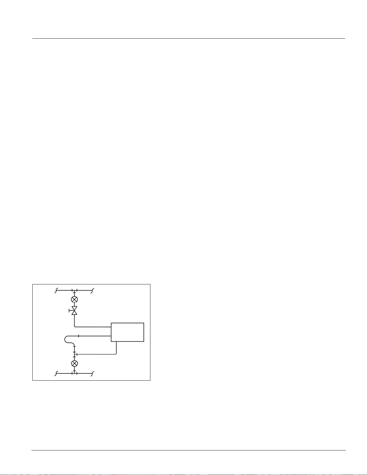
Valve Selection
Steam Valve Piping
Note: Piping packages can be purchased from McQuay or
provided by others
End-of-cycle (EOC) and modulating valves for steam
applications are 2-way, normally open, angle pattern
valves. When the coil is de-energized (off) the steam
flows through the coil. Energizing the EOC valve sh uts
off the flow of steam to the coil. Energizing the
modulating valve varies the flow of steam in a
modulating fashion. Refer to the steam valve label to
determine the direction of flow. The steam valve must be
installed on the unit for which it was selected.
All valves are shipped loose to help prevent shipping
t
damage and to provide the ins
maximum flexibility in making the field piping connection.
The valves are field piped by others. They are factory
wired for field hook-up.
Notes:
1 Refer to
the label furnishe
determine direction of flow through the valve.
2 The control va
lve must be installed on the unit in
which it was shipped. Indiscriminate mixing of valves
among units can result in valves not proper ly sized for
the desired flow rate.
e control valve should be installed so that there is
3 Th
2
" (51mm) minimum clearance to remove the actu ator
from the valve body . Provide u nions for the removal of
the unit coil and/or control valve. This is a future
service consideration.
alling contractor with
d on 2-way valves to
Figure 56. 2-Way Steam Valve Piping
Supply
Shutoff Valve
Unit Coil
Supply
Steam Trap
Equalizing Line
Shutoff Valve
Return
Return
AAF-HermanNelson Model AZ Unit Ventilators 53
Page 54
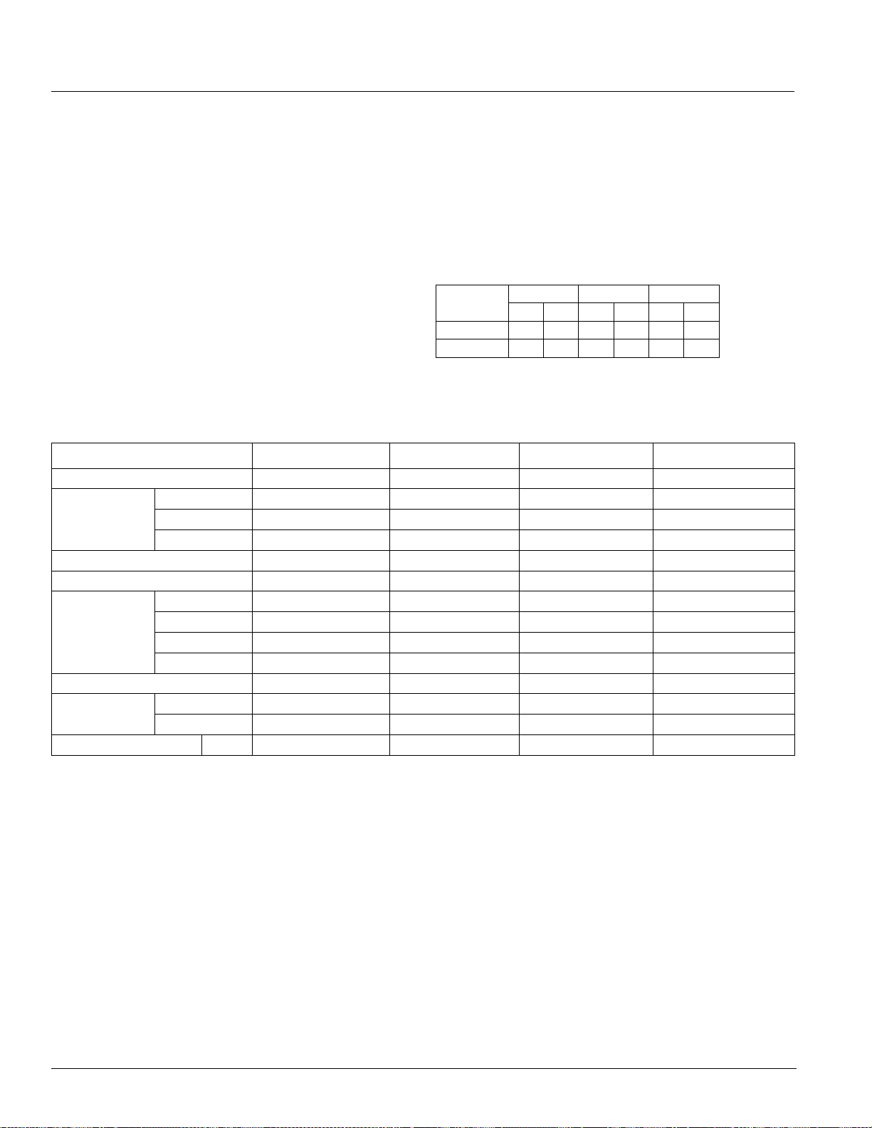
Details & Dimensions
Details & Dimensions
Coil Connections
The dimensional drawings on pages 55 and 56 show the
location of coil connections for hot water and steam.
The following notes apply to all units:
1 All coils have same-end supply and return
nections.
con
2 Steam coils have a factory-installed pressure
qualizing valve and a 24" (610mm) long pressure
e
equalizing line which terminates in a 1/2" M.P.T. fitting.
3 Steam or Hot Water connections are on the left end.
4 Electric heating coil power connections are right end
nly. Junction box has 1" (25mm) and 2" (51mm)
o
(trade size) knockouts, 10-1/2" (267mm) from right
end of the unit.
Table 25: Model AZ Basic Unit Data
Size S024 S036 S044 S054
Nominal Airflow - CFM (L/S)
No. of Fans 3 4 4 4
Room Fan Data
Room Fan Motor Horsepower
Outdoor Fan Motor Horsepower
Filter Data
Approx. Ship Weight - LBS. (Kg)
Coil Water Volume
Gallons (Liters)
Refrigerant Charge
Dia. In. (mm) 8.12 (206) 8.12 (206) 8.12 (206) 8.12 (206)
Width - In (mm) 8.25 (210) 8.25 (210) 8.25 (210) 8.25 (210)
Nom. Size - In. 10 x 48-1/2 x 1 10 x 60-1/2 x 1 10 x 36-1/2 x 1 10 x 36-1/2 x 1
Nom. Size - mm 254 x 1232 x 25 254 x 1527 x 25 254 x 927 x 25 254 x 927 x 25
Area - Ft² (M²) 3.37(.31) 4.2(.39) 5.08(.47) 5.08(.47)
1 Row Coil 0.31(1.17) 0.38(1.44) 0.44(1.67) 0.44(1.67)
2 Row Coil 0.57(2.16) 0.69(2.61) 0.82(3.10) 0.82(3.10)
Quantity 1.00 1.00 2.00 2.00
Ozs 125 140 150 150
1000(472) 1250(590) 1500 (708) 1500 (708)
1/4 1/4 1/4 1/4
1/3 1/3 3/4 3/4
885(402) 975(442) 1075(448) 1075(448)
5 Coil connecti
ons are 7/8" I.D. (female) and terminate
9" (229mm) from the end of the unit.
6 Steam coils are 1-1/8" female (sweat) connections
d terminate 9" (229mm) from the end of the unit.
an
7 All dimensions are approximate.
Table 24: Coil Water Capaci
Unit Series
1 Row Coil
2 Row Coil
024 036 044, 054
Gal Liter Gal Liter Gal Liter
0.29 1.10 0.35 1.32 0.41 1.55
0.52 1.97 0.63 2.38 0.74 2.80
ties (Gallons/Liters)
54 McQuay Catalog 1620
Page 55

Details & Dimensions
Coil Connection Locations
Figure 57. Hot Water Coil Connection Locations
28" Type
13¾"
(349mm)
Wall
8½"
(216mm)
Wall
Room Projection
17¾"
(451mm)
22" (559mm)
DX Coil
S
R
Room Projection
13¾"
(349mm)
8½"
(216mm)
Wall
11
(295mm)
15
Wall
Room Projection
DX Coil
R
5
"
8
/
7
" (403mm)
8
/
Room Projection
S
Left End View
Heating Coils
65 = 1-row Hot Water Coil
66 = 2-row Hot Water Coil
S = Supply
R= Return
DX Coil
13¾"
(349mm)
8½"
(216mm)
3
"
9
8
/
(238mm)
5
" (346mm)
13
8
/
*Shading indicates portion of unit wall sleeve recessed into wall opening
S
13¾"
(349mm)
8½"
(216mm)
3.62" (92mm)
Notes:
1. Water coil connections are 7/8" (22mm) female sweat and
DX Coil
RR
12.12"
(308mm)
S
terminate 9" (229mm) from the left end of the unit.
2. All coils have the supply and return connections in the left hand compartment.
3. All dimensions are approximate.
AAF-HermanNelson Model AZ Unit Ventilators 55
Page 56
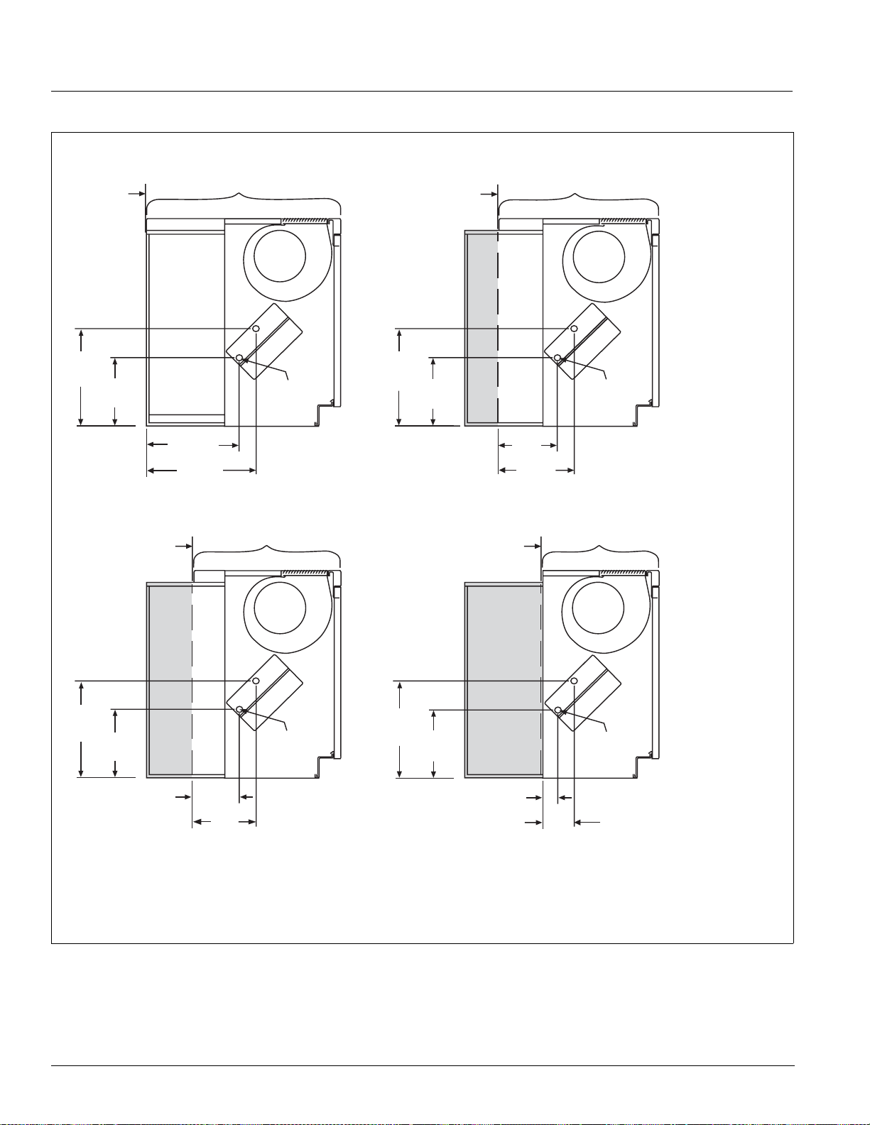
Details & Dimensions
Figure 58. Steam Coil Connection Locations
14½"
(368mm)
Wall
3
/16"
10
(259mm)
Wall
28" Type
Room Projection
Wall
Type
Room Projection
SS
14½"
To Steam
(368mm)
Trap
14¼"
(362mm)
7
16
/16"
(418mm)
Type Type
Room Projection
3
/16"
10
(259mm)
11
8
(221mm)
(273mm)
Wall
/16"
10¾"
To Steam
Trap
Left End View
Heating Coils
68 = Low Capacity Steam Coil
69 = High Capacity Steam Coil
S = Supply
Room Projection
SS
14½"
(368mm)
3
/16"
10
(259mm)
(162mm)
1
8
(205mm)
To Steam
Trap
/16"
14½"
(368mm)
3
10
/16"
(259mm)
Notes:
To Steam
Trap
1
5
(129mm)
/16"
1. Steam coil connections are 1-1/8" (29mm) female sweat and
*Shading indicates portion of unit wall sleeve recessed into wall opening
terminate 9" (229mm) from the left end of the unit.
2. All coils have the supply and drain to steam trap connections in the left hand
compartment.
3. Steam coils have a factory installed pressure equalizing line which
terminates in a 1/2" (13mm) MPT
4. All dimensions are approximate.
56 McQuay Catalog 1620
Page 57
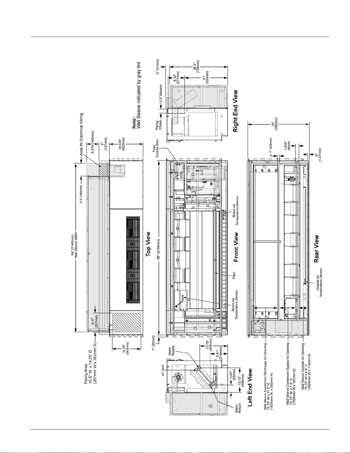
Details & Dimensions
Model AZ Self Contained Unit Dimensions, 024
Note: Valve control unit shown, however
face & bypass units have same
external dimensions.
AAF-HermanNelson Model AZ Unit Ventilators 57
Page 58

Details & Dimensions
Model AZ Self Contained Unit Dimensions, 036
Note: Valve control unit shown,
however face & bypass units
have same external dimensions.
58 McQuay Catalog 1620
Page 59

Details & Dimensions
Model AZ Self Contained Unit Dimensions, 044, 054
Note: Valve control unit shown, however
face & bypass units have same
external dimensions.
AAF-HermanNelson Model AZ Unit Ventilators 59
Page 60

Details & Dimensions
End Panels
Table 26: 1" (25mm) End Panel Dimensions
Top View
End View with
no Cutouts
End View with
2-1/2 x 7”
(64 x 178mm)
Cutout
End View with
4 x 18”
(102 x 457mm)
Cutout
16-5/8" (422mm)
Deep End Panel
16 5/8"
(422mm)
(178mm)
2
(64mm)
18"
(457mm)
4"
(102mm)
7"
1
2"
/
(25mm)
27 7/
(708mm)
1"
(25mm)
(708mm)
1"
(25mm)
(708mm)
1"
27 7/
27 7/
8"
8"
8"
19-5/8" (422mm)
Deep End Panel
5
8
/
19
(498mm)
1
2
/
2"(64mm)
(457mm)
(102mm)
"
7"
(178mm)
18"
4"
(25mm)
27 7/
(708mm)
1"
(25mm)
1"
(25mm)
1"
8"
27 7/
(708mm)
27 7/
(708mm)
21-7/8" (422mm)
Deep End Panel
7
21
8
/
"
(556mm)
7"
(178mm)
1
2
/
8"
8"
2"(64mm)
18"
(457mm)
4"
(102mm)
(25mm)
27 7/
(708mm)
1"
(25mm)
1"
(25mm)
1"
8"
27 7/
8"
(708mm)
27 7/
8"
(708mm)
28" (422mm)
Deep End Panel
28"
(711mm)
1"
(25mm)
27 7/
8"
(708mm)
End View with
4 x 22”
(102 x 559mm)
Cutout
22"
(559mm)
4"
(102mm)
1"
(25mm)
(708mm)
27 7/
8"
(559mm)
4"
(102mm)
22"
1"
(25mm)
(708mm)
27
1"
(25mm)
7
8"
/
22"
(559mm)
4"(102mm)
27 7/
8"
(708mm)
22"
(559mm)
4"(102mm)
1"
(25mm)
(708mm)
27 7/
8"
Table 27: 6" (152mm ) End Pan e l Di me nsions
28"
(711mm)
6"
(152mm)
27"
(686mm)
3" (76mm)
Top View
End View with
no Cutouts
16 5/8"
(422mm)
6"
(152mm)
27"
(686mm)
3" (76mm)
19 5/8"
(498mm)
6"
(152mm)
27"
(686mm)
3" (76mm)
21 7/8"
(556mm)
6"
(152mm)
27"
(686mm)
3" (76mm)
60 McQuay Catalog 1620
Page 61

Details & Dimensions
Valve Dimensions
Note: Valves ordered separately
Face & Bypass End Of Cycle Valves
Figure 59. 2-Way EOC Valve
3-11/16"(94mm)
3-1/4"(83mm)
1-1/4"(32mm)
Y
2-9/16"(66mm)
3/4"(19mm)
3/4"(19mm)
Modulating Valves
Figure 61. 2-Way Modulati ng Valve
4-3/32"
104mm
3-5/32"
80mm
6-13/16"
C
173mm
3-19/32"
80mm
11/32"
8mm
X
X, Y, Z Dimensions
Connection Cv X Y Z
3/4"(19mm) FNPT 7.0 11-1/16" (43mm) 1-1/16" (23mm) 3-5/8" (92mm)
*1"(25mm) FNPT 7.0 1-7/8" (47mm) 1" (25mm) 31-1/16" (94mm)
X
Z
Figure 60. 3-Way EOC Valve Modulating Valves
3-11/16"(94mm)
3-1/4"(83mm)
1-1/4"(32mm)
1-11/6"
43mm
1-11/6"
43mm
3-5/8"(92mm)
2-3/8"(61mm)
3-1/16"(81mm)
1-7/16"
37mm
2-9/16"(66mm)
3/4"(19mm)
3/4"(19mm)
Table 28: Actuator Specifications
Control
Electrical
Stroke
Ambient
2 Position
24 VAC, 50/60 Hz
Power Stroke 9 to 11 seconds
Spring return 4 to 5 seconds
32°F to 125°F (0°C to 52°C)
Table 29: F&B Valve Body Specifications
2-Way Valve 3-W ay Valve
Connections
Static Pressure
Close-Off Pressure
Temperature
3/4" FNPT, 1" FNPT 3/4" FNPT
300 psi (2100 kPa) 300 psi (2100 kPa)
13 & 15 psi (90 & 103 kPa) 13 psi (90 kPa)
32°F to 200°F (0°C to 93°C) 32°F to 200°F (0°C to 93°C)
B
A
Figure 62. 2-Way Modulati ng Valve
3-15/16"
100mm
3-5/32"
80mm
C
B
4-3/32"
104mm
A
11/32"
8mm
6-13/16"
173mm
Table 30: 2-Way and 3-Way Modulating Valve Dimensions
Valve Size
in (DN)
1/2 (DN15) 3 (76) 13/16 (21) 1-9/16 (39) 1-13/16 (46) 8 (203)
3/4 (DN20) 3-7/32 (81) 15/16 (24) 1-5/8 (41) 2-1/8 (54) 8 (203)
1 (DN25) 4-1/8 (1 19) 1-5/32 (29) 1-3/4 (44) 2-9/16 (65) 9-7/32 (234)
1-1/4 (DN32) 4-23/32 (119) 1-11/32 (34) 2 (51) 2-25/32 (70) 9-7/32 (234)
A B C
N.O./N.C./
Three-Way
2-Way
N.O.
2-Way
N.C.
Three-
Way
C
Table 31: Actuat or Specifications
Control
Electrical
Transformer
Stroke
Operating Temp
35 to 250°F (2 to 121°C); 15 psig (103 kPa)saturated steam
Floating Point Modulating
20 to 30 VAC at 50/60 Hz or 24 VDC ± 10%
12 VA (class 2 power source)
29/32 in. (23mm) max. 76 seconds
Table 32: Modulati ng Valve Body Specifications
Connections
Static
Pressure
Fluid Temperature
400 psig (2.756 PA) up to 150°F; (66°C) decreasing to 365
Water
Steam
35 to 250°F (2 to 121°C); 15 psig (103kPa) saturated steam
psig; (2,515 kPa) at 248°F (120°C)
38 psig (262 kPa) Saturated steam at 284°F
AAF-HermanNelson Model AZ Unit Ventilators 61
Page 62

Details & Dimensions
Wall Intake Louvers & Grilles
Louvers are available with a vertical blade con figur ation,
constructed of heavy-gauge (unpain ted, p ainted, or clear
anodized) aluminum.
• The louver is divided in half horizontally to prevent
enser air recirculation.
cond
• A bird screen is provided on the leaving air side of the
ake louver.
int
• Louvers can be supplied with or without flanges:
• Flanged louvers are typically used for a panel wall
finish.
• Unflanged louvers are typically used for recessing
a masonry wall.
into
• An optiona
l (factory-mounted) heavy-duty lattice
exterior grille is available with horizontal and vertical
lines that “line up” with the louver blades to present an
aesthetic appearance.
vers are available in both horizontal and vertical
• Lou
bla
de configurations:
Figure 63. Typical W a ll Lo uver and Grille
Factory Mounted
Bird Screen
Bird Screen
Fasteners
Information
Labels
Frame
Optional
Flanges
Splitter Lines
Up with Wall
Sleeve Splitter
Figure 65. Grille Detail
1
/2"
2
(63.5 mm)
W (see Table)
A (see Table)
++
28"
(711 mm)
/8"
1
+
+
+
+
+
+
+
+
+
+
14±
(356±3.2mm)
+
1 1/4"
(31.8 mm)
+
7
/8"
(22.2 mm)
Optional Flange
Table 33: W a ll Lo uv er Dimensions (W)
Unit Size
024
036
044, 054
Louver Size
(Height x W)
28” x 84”
(711 x 2134)
28” x 96”
(711 x 2438)
28” x 108”
(711 x 2743)
Discharge Air
Opening(A)
9”
(229mm)
9”
(229mm)
7”
(178mm)
Note: All dimensions are approximate and subject to change
without notice. Refer to approved submittal prints for
rough-in details and construction purposes, and for
recommended wall opening size.
Optional Factory
Mounted
Exterior Grille
Mechanical
Fasteners
Figure 66. Vertical Blade Louver, Without Flange
Inside View
Condenser
Discharge Air
Figure 64. Vertical Blade Louver, Without Flange
Outside View
Condenser
Discharge Air
Condenser
Inlet Air
Bird Screen on
Side Toward Unit
Condenser
Inlet Air
Louver with
Weep Holes
62 McQuay Catalog 1620
Page 63

Details & Dimensions
VentiMatic Shutter Assembly
Notes:
1 Horizontal blade louver shown. Vertical blade louver
also available with Ventimatic shutter.
2 Optional exterior grille matches unit
ventilator louver
in material and design. Mounted in wall louver.
Figure 67. Ventimatic Shutter Assembly With Optional Grille
3 Optional interior grille mounting hardware is
included.
4 Louver leaves seal against plate to pr
event air
infiltration.
not
Table 34: Ventimatic Shutter Assembly Dimensions & Max Air
Exterior Grille
Width A
inches mm inches mm inches mm
23-3/4 603 24 610 27 686 24-1/4 616 10-1/2 267 1 0 500 236
36-3/4 933 36 914 39 991 36-1/4 921 10-1/2 267 0 1 750 354
47-3/4 1213 48 1219 51 1295 48-1/4 1225 10-1/2 267 2 0 1000 472
59-3/4 1518 60 1524 63 1600 60-1/4 1530 10-1/2 267 1 1 1250 590
71-3/4 1822 72 1829 75 1905 72-1/4 1835 10-1/2 267 0 2 1500 708
Louver
Width B
Interior Grille
Width C
Recommended Wall Opening
Length Width
inches mm inches mm
Capacities
For Louver
Max Number of Ventimatic
rs To Mount On
Shutte
Standard Louver
24” (610mm)
Shutter
36” (914mm)
Shutter
Ventimatic
Shutter(s) Max
Air Capacity
inches mm
AAF-HermanNelson Model AZ Unit Ventilators 63
Page 64
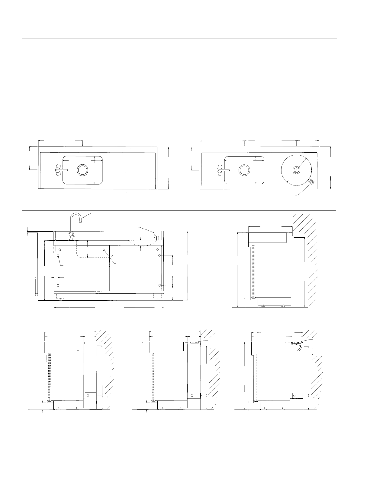
Details & Dimensions
Sink & Bubbler Cabinet
Notes:
1 Sink top is one-piece, stainless steel construction with
sound-deadening coating on the under side. Front
edge has raised lip continuously from end to end.
2 Sliding doors available in decorator colors.
Figure 68. Top View - Single Bowl & Bowl With Bubbler
17-7/8" 454mm
9-5/16"
228mm
Figure 69. Front & End Views
1/8" (3mm)
16" 392mm
11-1/8"
283mm
Faucet
Bubbler
3 Sink and bub
bler basin drains equipped with 1-1/2"
O.D. tail pieces, all chrome plated brass.
4 Sink faucet and bubbler valve are shipped loose for
field ins
5 Sink and bub
tallation by the installing contractor.
bler top is designed to project 1/16"
higher and 3/16" deeper than the adjoining cabinets,
unit ventilator or end panels.
12" 25mm
9-1/8"
232m
427mm
16-13/16"
17-7/8" 454mm
9-5/16"
228mm
427mm
16-13/16"
16" 392mm
21" 533mm
11-1/8"
283mm
16-13/16"
427mm
Bubbler
(4) 7/8" (22mm) Dia.
26"
660mm
1"
25mm
3"(76mm)
Knockouts In Back For
Anchoring To Wall
1-9/16"
40mm
21-7/8" (556mm)
16-13/16"(427mm)
21-7/8"(556mm) Deep Cabinet
Right End View
48" (1219mm)
Front View
23"
584mm
5"
127mm
Door Lock
(Optional)
2-1/2"
64mm
21-7/8" (556mm)
16-13/16"(427mm)
3"(76mm)
30-1/8"
765mm
13-1/2"
765mm
6-1/2"
165mm
21-7/8"(556mm) Deep Cabinet
With Radiation Bar Grille
Radiation
Bar Grille
23"
584mm
5"
127mm
30-1/8"
765mm
16-13/16"(427mm) Deep Cabinet
Right End View
21-7/8" (556mm)
16-13/16"(427mm)
3"(76mm)
21-7/8"(556mm) Deep Cabinet
With Draftstop Bar Grille & Damper
28-1/8"
714mm
23"
584mm
5"
127mm
Draftstop
Bar Grille
& Damper
64 McQuay Catalog 1620
Page 65
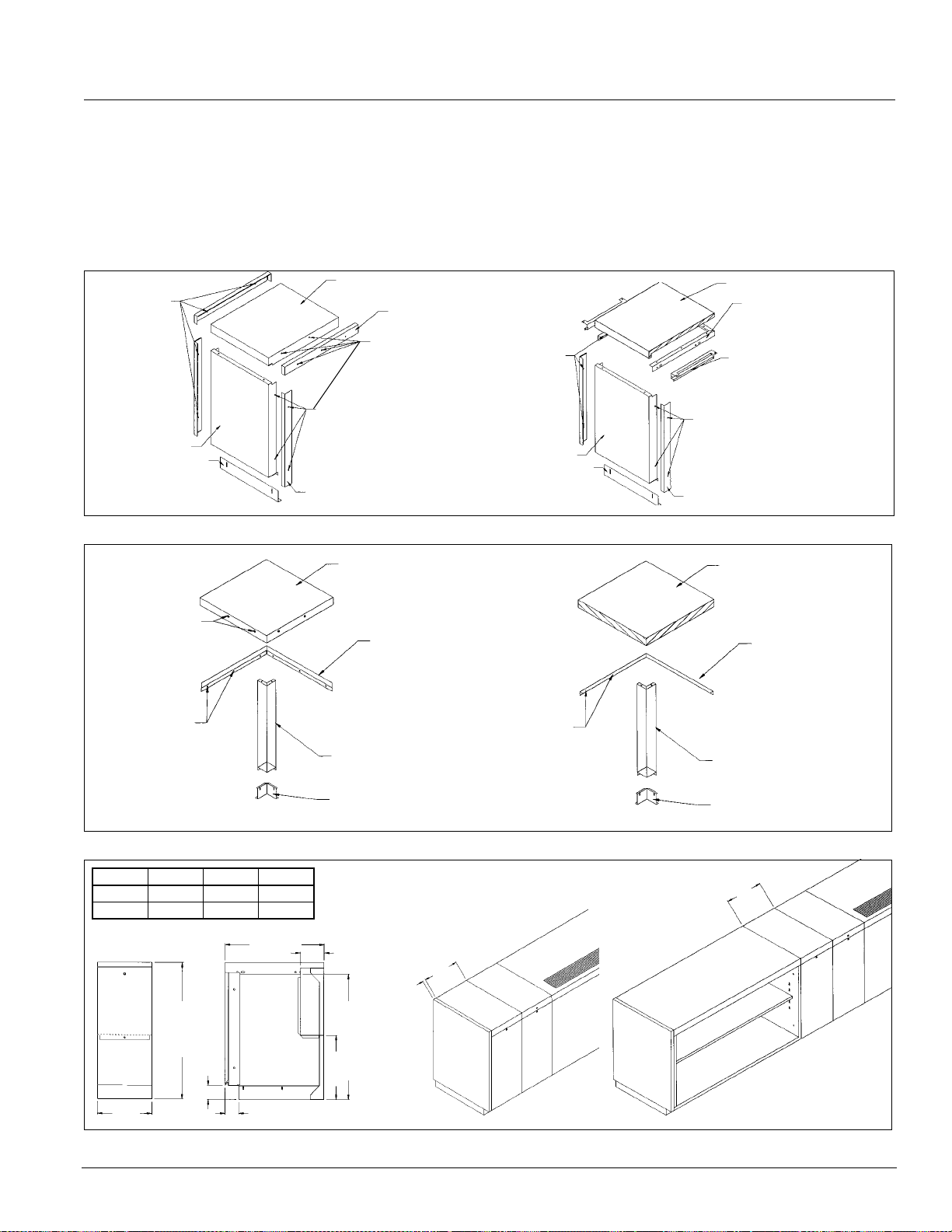
Details & Dimensions
Filler Sections & Utility Compartment
Filler sections are furnished in 18" and 24" lengths. They
are provided with enough hardware to assemble one
right hand and one left hand fi ller having a combined
after cutting is 3". The filler section may be used between
a cabinet and the wall, between a unit and the wall,
between a unit and cabinets, or between cabinets.
length of 18"/24" or less. The minimum length of one filler
Figure 70. Wall Filler Section With Painted Metal Or Laminate Top
Painted Metal Top
Attach to wall,
left or right end.
Front
Kickplate
Front End Cap
Figure 71. Corner Filler Sections
Attach to unit
ventilator, storage
cabinet right.
Top End Cap
Attach to unit
ventilator or utility
cabinet right or left
end.
Painted Metal Top
Support Strip
Attach to wall,
left or right end.
Front
Kickplate
Laminate Top
Mounting Angle for attaching
top to unit ventilator, utility
cabinet and back wall.
Side Panel Adapter
for attaching top to
storage cabinet.
Attach to unit ventilator
or storage cabinet right
or left end.
Front End Cap
Laminate Top
Support Strip
Attach to wall
Figure 72. 12" Utility Compartment
Dim. A MM Dim. B MM
16-5/8 442 3 76
21-7//8 556 5-1/4 133
A
30"
762mm
3"
76mm
12"
305mm
3" (76mm)
B
Corner Post
Kickplate
28"
660mm
14"
356mm
Attach to wall
Corner Post
Kickplate
12"
305mm
12"
305mm
1" 25mm
AAF-HermanNelson Model AZ Unit Ventilators 65
Page 66
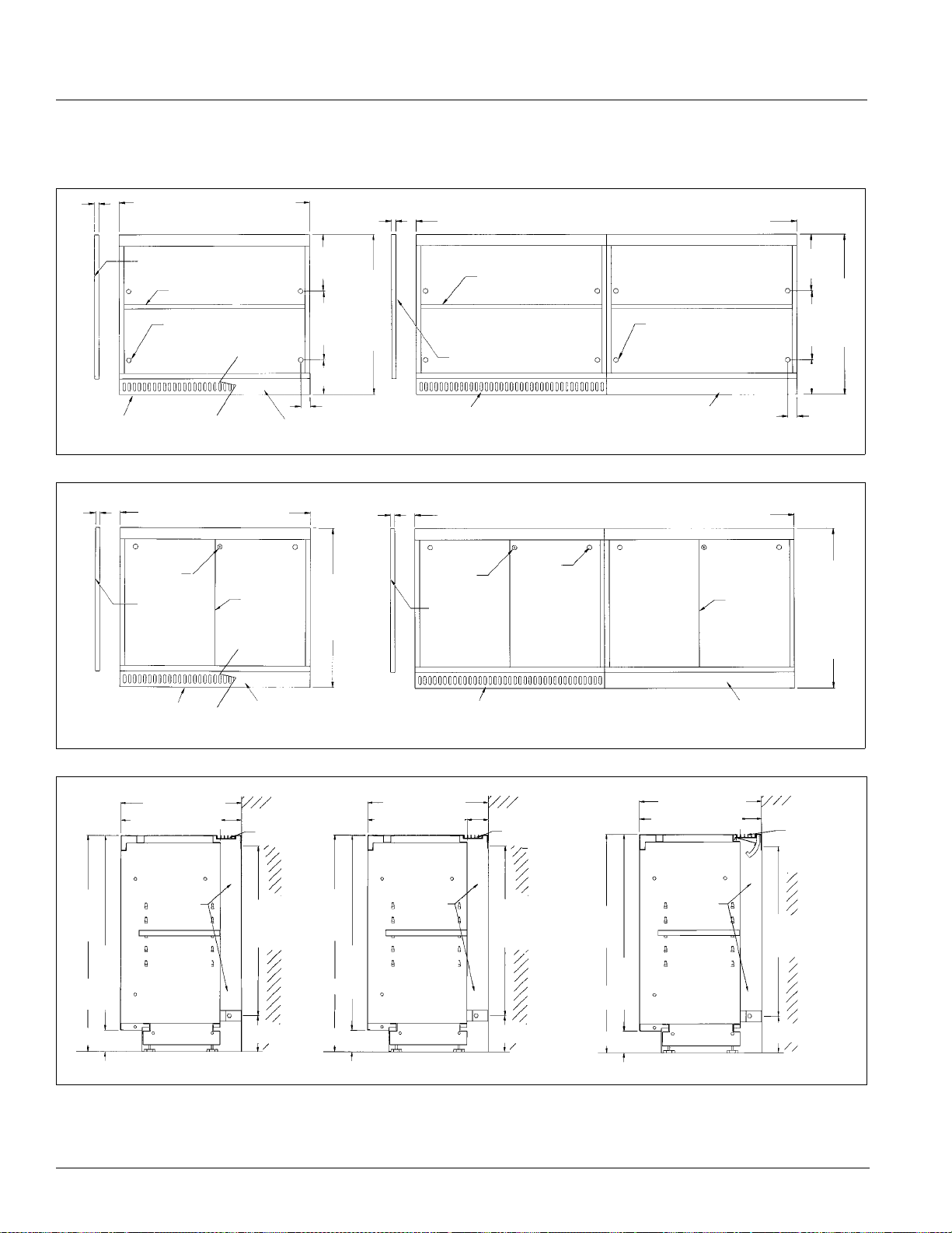
Details & Dimensions
Shelf Storage Cabinets
Figure 73. Shelf Storage Cabinets, Front View
1"
25mm
24, 36, 48 & 60" open
(610, 914, 1219 & 1524 mm)
1"
25mm
72, 84, 96, 108 & 120" open (1829, 2134, 2438, 2743 & 3048mm )
10"
254mm
762mm
13-1/2"
343mm
6-1/2"
165mm
1-9/16" (40mm)
Removable end panels
Shelf adjustable in 2"
(51mm) increments
4-7/8" (22mm) diameter
knockouts in back for
anchoring to wall
Front skirt with air inlet for
radiation style cabinet
Front skirt for standard and
draftstop style cabinet
Figure 74. Shelf Storage Cabinets, Front View
1"
25mm
Front skirt with air inlet for
radiation style cabinet
24, 36, 48 & 60" open
(610, 914, 1219 & 1524 mm)
Door lock
(optional)
Removable
end panels
Sliding
doors
Front skirt for standard and
draftstop style cabinet
30"
762mm
30"
1"
25mm
Shelf adjustable in 2"
(51mm) increments
Removable end panels
Front skirt with air inlet for
radiation style cabinet
72, 84, 96, 108 & 120" open (1829, 2134, 2438, 2743 & 3048mm )
Door lock
(optional)
Removable
end panels
Front skirt with air inlet for
radiation style cabinet
Door pull
4-7/8" (22mm) diameter
knockouts in back for
anchoring to wall
Front skirt for standard and
draftstop style cabinet
Sliding
Doors
Front skirt for standard
and draftstop style cabinet
10"
254mm
30"
762mm
13-1/2"
343mm
6-1/2"
165mm
1-9/16"
40mm
30"
762mm
t
Figure 75. Right End View - 16-5/8" (442 mm) Deep Shelf S
16-5/8" (442mm)
13-11/16" (348mm)
27"
30"
762mm
686mm
3" (76mm)
16-5/8" (442mm)
13-11/16" (348mm)
27"
Piping
area
2-15/16
(75mm)
23"
584mm
5" (127mm)
"
30"
762mm
686mm
3" (76mm)
orage Cabinets With 11-1/2" (292mm) Shelf & Metal Top
16-5/8" (442mm)
13-11/16" (348mm)
Piping
area
27"
Piping
area
2-15/16" (75mm)
Radiation bar grille
23"
584mm
5" (127mm)
30"
762mm
686mm
3" (76mm)
2-15/16" (75mm)
Draftstop
bar grille
& damper
23"
584mm
5" (127mm)
Standard Cabinet Cabinet With Radiation Bar Grille Cabinet with DraftStop Bar Grille & Damper
66 McQuay Catalog 1620
Page 67
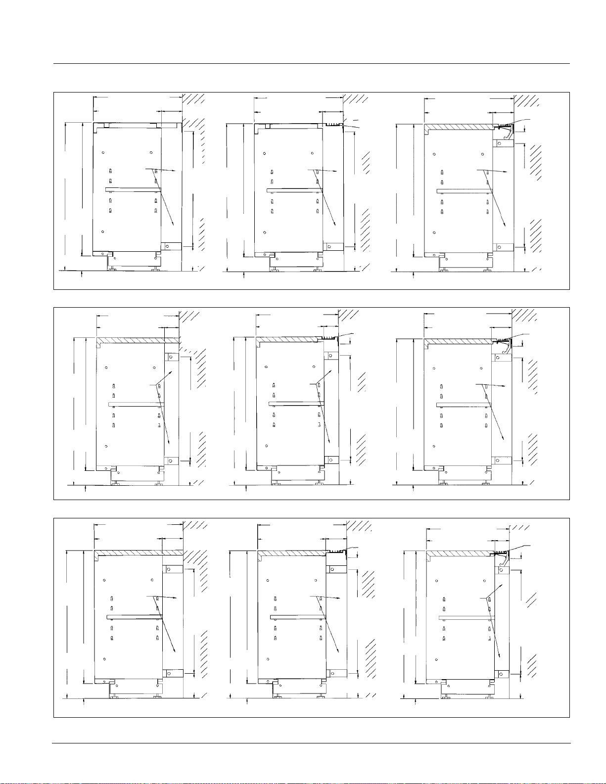
Details & Dimensions
Figure 76. Right End View - 21-7/8" (556 mm) Deep Shelf Storage Cabinets With 13-1/2" (343mm) Shelf With Metal Top
21-7/8" (556mm)
16-1/16" (408mm)
5-13/16
148 mm
"
21-7/8" (556mm)
16-1/16" (408mm)
5-13/16" (148)
Radiation
bar grille
21-7/8" (556mm)
16-1/16" (408mm)
5-13/16"(148 mm)
Draftstop
bar grille
& damper
30"
762mm
27"
686mm
3" (76mm)
Piping
area
23"
584mm
5"
127mm
30"
762mm
27"
686mm
3" (76mm)
Standard Cabinet Cabinet With Radiation Bar Gr ille Cabinet with DraftStop Bar Grille & Damper
Figure 77. Right End View - 16-5/8" (442 mm) Deep
16-5/8" (442mm)
30"
762mm
686mm
13-11/16" (348mm)
Piping
area
27"
2-15/16
(75mm)
23"
584mm
"
30"
762mm
27"
686mm
Piping
area
23"
584mm
5"
127m
30"
762mm
27"
686mm
3" (76mm)
Piping
area
23"
584mm
5" (127mm)
Shelf Storage Cabinets With 11-1/2" (292mm) Shelf With Laminate Top
27"
16-5/8" (442mm)
13-11/16" (348mm)
Piping
area
2-15/16" (75mm)
Draftstop
bar grille
& damper
23"
584mm
16-5/8" (442mm)
13-11/16" (348mm)
Piping
area
2-15/16" (75mm)
Radiation
bar grille
23"
584mm
30"
762mm
686mm
3" (76mm)
5" (127mm)
3" (76mm)
5" (127mm)
3" (76mm)
5" (127mm)
Standard Cabinet Cabinet With Radiation Bar Grille Cabinet with DraftStop Bar Grille & Damper
Figure 78. Right End View - 21-7/8" (556 mm) Deep Shelf S
21-7/8" (556mm)
5-13/16
"
148 mm
23"
584mm
5"
127mm
16-1/16" (408mm)
30"
762mm
27"
686mm
3" (76mm)
30"
762mm
686mm
3" (76mm)
16-1/16" (408mm)
Piping
area
27"
torage Cabinets With 13-1/2" (343mm) Shelf With Laminate Top
21-7/8" (556mm)
Piping
area
5-13/16" (148)
Radiation
bar grille
23"
584mm
5"
127mm
30"
762mm
27"
686mm
3" (76mm)
21-7/8" (556mm)
16-1/16" (408mm)
Piping
area
5-13/16"(148 mm)
Draftstop
bar grille
& damper
23"
584mm
5" (127mm)
Standard Cabinet Cabinet With Radiation Bar Grille Cabinet with DraftStop Bar Grille & Damper
AAF-HermanNelson Model AZ Unit Ventilators 67
Page 68

Wiring Diagrams
Wiring Diagrams
Typical MicroTech II Wiring Diagrams
Note: For troubleshooting, refer to unit-mounted schematic
Figure 79. MicroTech II Wiring Diagram
68 McQuay Catalog 1620
Page 69
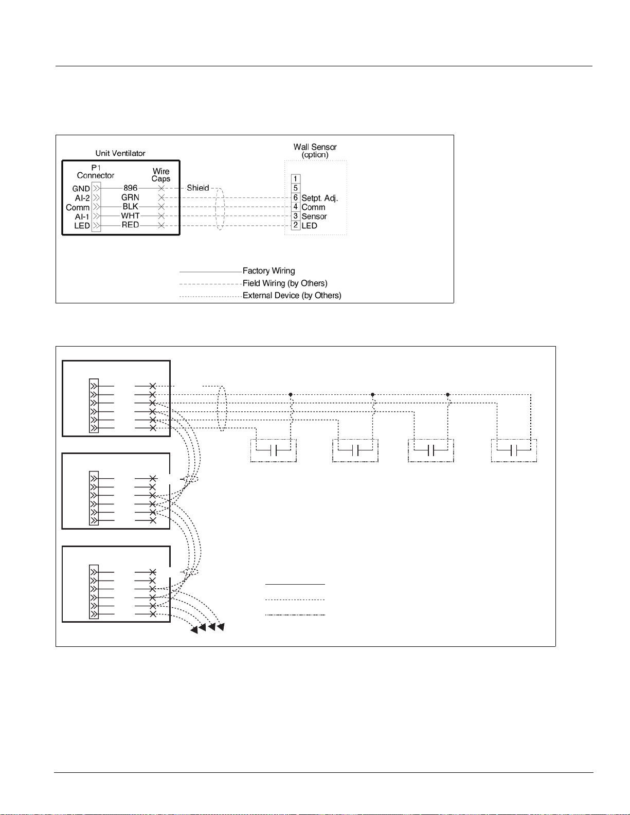
Wiring Diagrams
Typical Wall Sensors Diagram
Figure 80. Wall-Mounted Temperature Sensor Wiring for Wall Sensor
Power & Control Field Wiring
Figure 81. External Input Wiring Examples with or without Daisy Chaining of Units
Unit Ventilator #1
Connector
GND
Comm
BI-6
BI-5
BI-4
BI-3
P1
896
908A
907A
906A
905A
904A
Wire
Caps
Shield
Unit Ventilator #2
P1
Connector
GND
Comm
BI-6
BI-5
BI-4
BI-3
Unit Ventilator #3
P1
Connector
GND
Comm
BI-6
BI-5
BI-4
BI-3
896
908A
907A
906A
905A
904A
896
908A
907A
906A
905A
904A
Wire
Caps
Wire
Caps
Shield
Shield
Additional Units
External Input
Option 4 Device
(by Others)
External Input
Option 3 Device
(by Others)
Ventilation Lockout
(default) or
Exhaust Interlock
External Input
Option 2 Device
(by Others)
Remote Shutdown
Factory Wiring
Field Wiring (by Others)
External Device (by Others)
External Input
Option 1 Device
(by Others)
Unoccupied
AAF-HermanNelson Model AZ Unit Ventilators 69
Page 70
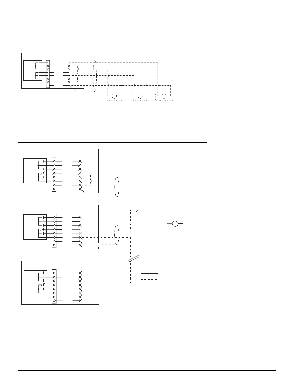
Wiring Diagrams
Figure 82. External Output Wiring - Single Unit
Unit Ventilator
UVC
xBO-2
Comm
xBO-1
BO-6
BO-6
Comm
24vac Supply
24vac Comm
P6
Connector
601A
602A
603A
604A
605A
606A
608A
610A
Wire
Caps
Shield
Factory Wiring
Field Wiring (by Others)
External Device (by Others)
External Output
Option 1 Device
(by Others)
Lights On/Off
Signal
or
Motorized Water
Valve Open/Close
External Output
Option 2 Device
(by Others)
Fault Indication
Pump Restart
Figure 83. External Output Wiring - Multiple Units Shown
Unit Ventilator #1
P6
Connector
UVC
XBO-2
Comm
XBO-1
BO-6
BO-6
Comm
24vac Supply
24vac Comm
Unit Ventilator #2
P6
Connector
UVC
XBO-2
Comm
XBO-1
BO-6
BO-6
Comm
24vac Supply
24vac Comm
Unit Ventilator #...X (last unit)
P6
Connector
UVC
XBO-2
Comm
XBO-1
BO-6
BO-6
Comm
24vac Supply
24vac Comm
601A
602A
603A
604A
605A
606A
608A
610A
601A
602A
603A
604A
605A
606A
608A
610A
601A
602A
603A
604A
605A
606A
608A
610A
Wire
Caps
Wire
Caps
Wire
Caps
Shield
Shield
Additional Units
or
Signal
External Output
Option 3 Device
(by Others)
Auxiliary Heat
Signal
or
Exhaust Fan
On/Off Signal
External Output
Option 2 Device
(by Others)
Fault Indication
or
Pump Restart
Signal
Factory Wiring
Field Wiring (by Others)
External Device (by Others)
70 McQuay Catalog 1620
Page 71

Guide Specifications
Guide Specifications
AAF-HermanNelson Unit Ventilator Model AZ Guide Specifications
General
Furnish and install where shown on plans, a complete
self-contained, air cooled, heating and cooling unit
ventilator. This unit shall meet capacities, airflow and
configuration as shown on unit schedule.
Each standard unit must be listed by Underwriters
aboratories Inc. (U.L.) as complying with all safety
L
standards.
The units shall ship fully assembled with the exception of
end panels which shall be packaged separately to
the
allow easy access for piping and electrical rough-in.
(Option: Wall sleeves shall be shipped in advance of unit
for rough-in.)
Unit Construction
All internal sheet metal parts subject to corrosion must
be made of galvanized steel. The entire frame must be
welded construction to provide strength and rigidity.
Frames assembled with sheet metal fasteners are not
acceptable.
Cabinets
Exterior cabinet panels shall be constructed of heavygauge steel and every exposed corner must be welded
and ground smooth for appearance and durability. All
surfaces shall be cleaned and phosphatized, then
painted with an oven baked powder paint. Top surface
shall be Charcoal Bronze textured powder paint to resist
scratching and hide fingerprints. Front access panels
and top access door shall be supplied with tamper
resistant fasteners.
Removable discharge grille shall be
continuous, round edged, steel bars to provide a 10degree vertical deflection.
Adjustable side deflection vanes shall be provided
eneath the discharge grille to give optimal lateral air
b
distribution. (Option: A 1/4" (6mm) mesh screen shall be
provided beneath the discharge grille to protect against
objects being dropped through the discharge grille.)
constructed of
Room Air Fans and Motor
The motor and fan assembly shall be low speed design
and shall be double inlet, forward curved centrifugal type
with maximum fan speed of 1100 rpm. Fan wheels shall
be constructed of dark, high density, injection molded
polypropylene having high impact strength, chemical
resistance and thermal stability. Assembly shall be direct
drive type and shall be statically and dynamically
balanced. Motor shall be permanent split capacitor
(PSC) plug-in type located out of the airstream and have
an internal thermal overload device (auto-reset). Fan
speeds shall be controlled by High-Med-Low-Off switch.
Fan/coil arrangement shall be draw-thru design for
uniform coil face velocity and discharge air temperature.
Fan motors and controls shall have each hot line
otected by factory installed cartridge type fuse(s) The
pr
unit manufacturer shall provide one (1) spare motor for
each size and type of motor furnished as part of a unit
ventilator, except units having double extended shaft
motors shall be provided with one (1) spare fan board
assembly for each unit size.
All components of the fan/motor assembly shall be
emovable from the front of the unit. The motor and fan
r
shaft shall have sleeve type bearings with precision
tolerances and shall not require oiling more than once
annually.
Condenser Fans and Motors
The fan board and fan housings shall be constructed of
galvanized steel. The fan motor and fan shaft shall have
permanently lubricated ball bearings. Motor shall be
permanent split capacitor (PSC) type. Fan wheels shall
be forward curved centrifugal type.
(Optional) Face and Bypass Damper
Each unit shall be provided with a factory-installed face
and bypass damper, constructed of aluminum. The long
sealing surfaces of the damper shall seal positively
against stops fitted with extruded EPDM rubber seals.
Face and bypass damper stop s not fitted with sea ls shall
not be acceptable. The damper ends shall have blended
mohair seals glued along the ends for a positive seal.
Plastic clip-on brush end seals will not be acceptable.
The unit design shall incorporate the face and bypass
damper to prevent coil surface wiping and be before the
fan in a draw through configuration. Face and bypass
damper positioned in the direct discharge of the room fan
is not acceptable. The face and bypass damper shall be
arranged so a dead air space results between the coil
and the damper in a full bypass condition to minimize
heat pick up.
Outdoor and Room Air Dampers
Each unit shall be provided with separate room air and
outdoor air dampers. The room air damper shall be
constructed of aluminum and counterbalanced against
AAF-HermanNelson Model AZ Unit Ventilators 71
Page 72

Guide Specifications
back pressure. Outdoor air damper shall be two-piece,
double wall construction with 1/2" (13mm) thick, 1.5 lbs.
(.68 kg) density fiberglass insulation sandwiched
between welded galvanized steel blades. Outdoor air
damper shall have additional foam insulation on the
exterior of the blades and end partitions. Dampers shall
be fitted with blended mohair seals along all sealing
edges. Damper bearings shall be made of nylon or other
material which does not require lubrication.
Refrigeration System
The refrigeration section shall be constructed of
galvanized steel and shall include a factory sealed,
factory piped assembly consisting of a hermetically
sealed compressor , a conden ser coil, cond enser fan and
motor, an d an evaporator coil. No condensate drain
piping system shall be required as the cooling
condensate is to be disposed of by directing it into the
condenser fan scrolls for re-evaporator on the hot
condenser coil. The equipment manufacturer is to be
fully responsible for the integrity of the refrigerant piping
and the entire refrigeration circult, including compressor.
Condenser and evaporator coils shall be fully assembled
and tested prior to shipment. The motor compressor unit
shall be vibration isolated internally and externally and
shall be connected in such a manner as to prevent
transmission of vibration to other components within the
section.
Single-phase only: Single-phas
permanent split capacitor (PSC) compressor motor with
compressor start relay.
Units with three-phase power: Shall utilize three-phase
pressors for balanced electrical compressor loads.
com
The condenser coil shall be constructed of copper tubes
chanically expanded to embossed aluminum plate
me
fins. The unit shall be so designed as to allow access to
the entering side of the condenser coil for cleaning
without opening the sealed refrigeration circuit. The
evaporator coil shall be constructed of copper tubing
having embossed aluminum plate fins mechanically
bonded thereto and shall be positioned above a plastic
drain pan.
Refrigerant shall be metered by a thermostatic
pansion valve in lieu of capillary tubing to achieve
ex
evaporator performance and to protect the compressor
from floodback of liquid refrigerant. The refrigerant
section shall be adequately insulated to prevent
“sweating.”
The unit shall be furnished and wired with compressor
rmal/current overload and high pressure cutout.
the
Gauge ports shall be provided to allow reading of
e units shall have
refrigerant pressures at the suction and discharge of the
compressor. Compressor shall be equipped with internal
pressure relief valve to protect against excessive
pressure buildup.
(Optional) Electric Coils
Heating elements shall be of the open wire type. Electric
heat shall be controlled in [three] stages. A capillary type
high limit thermostat shall be provided to disconnect the
heating elements through backup contactors if an
overheat condition is detected. A front panel interlock
switch shall be furnished to de-energize the electric
resistance heating element when center front panel is
opened.
(Optional) Hot Water Coil
Coil shall be aluminum plate fin and copper tube
construction. Coil shall be suitable for 150 psi working
pressure. Coil shall be provided with an accessible
manual air vent at the high point of the coil and a
threaded drain plug at the low point of the coil.
Contractor shall prov
shutoff valves and union connections in both the supply
and return piping connections to permit removal of the
unit from the wall sleeve for servicing.
Option: C
way) modulating control valve and shall be factory wired
by the unit ventilator manufacturer. Valve shall be field
installed and piped by the installing contractor.
— OR —
Option: Co
and bypass damper. Coil shall have a 3-way, 2-position,
end-of-cycle valve to shut off water flow when heating is
no longer required. V alve and coil return shall have union
connections. Valve shall be factory wired by the unit
ventilator manufacturer and shall be field installed and
piped by the installing contractor.
oil shall be controlled by a 3-way (optional 2-
il shall be controlled by a modulating face
ide all necessary balancing valves,
(Optional) Steam Coil
Coil shall be aluminum plate fin and copper tube
construction. Coil shall be double tube (D T) ste am
distributing, freeze resistant type. Coil shall be pitched to
insure complete condensate removal for freeze
protection and elimination of “water hammer.”
Contractor shall provide all necessary shutoff valves and
ion connections in both the supply and return piping
un
connections to permit removal of the unit from the wall
sleeve for servicing.
A pressure equalizing device (vacuum breaker) shall be
factory inst
alled to prevent the retention of condensate in
72 McQuay Catalog 1620
Page 73

Guide Specifications
the coil. The installing contractor shall connect the device
to the return line beyond the trap using the tubing
provided. Steam tra p shall be furnished and field
installed by the installing contractor.
Option: Co
control valve and shall be factory wired by the unit
ventilator manufacturer. Valve shall be field installed and
piped by the installing contractor.
— OR —
Option: Co
and bypass damper. Coil shall have a 2-way, 2-position,
end-of-cycle valve to shut off steam when heating is no
longer required. Valve and coil supply shall have union
connections. Valve shall be factory wired by the unit
ventilator manufacturer. Valve shall be field installed and
piped by the installing contractor.
il shall be controlled by a 2-way, modulating
il shall be controlled by a modulating face
(Optional) Up-feed Piping.
Option: Up-feed piping stub-up within the unit end
compartment requires the installing contractor to furnish
union connection at the floor line in the supply and return
lines with shutoff valves below the floor line. This is
required to permit unit installation and removal for
servicing.
Option: Up
external to the unit within a removable 6", (152m m ) wide
end panel. The shutoff valves and union connections
shall be located within the 6" (152mm) wide end panel.
-feed piping stub-up shall be brought up
Filter
Filter shall be one-piece design located to provide
filtration of the outdoor air/return airflow. Separate filters
for outdoor air and return air are not acceptable.
Throwaway filter shall be factory furnished initially
installed in the unit.
multi-functional material that serves as a sound barrier,
an absorber of sound and also must act as a decoupler
to the compressor enclosure. This multi-functional
material shall have a mylar coating on the face to act as
a sound reflector and to increase the strength of the
material. Damping material shall be textured foam type.
The exterior of the compressor compartment shall be
ted with a high density damping material to eliminate
coa
impact noise and vibration. The right-hand front panel
and the hinged top access door shall be coated with a
high density material to minimize noise and vibration.
Temperature Controls
The unit ventilator manufacturer shall provide factory
installed, calibrated, and tested temperature controls.
Units that are capable of providing up to 100% outside
air shall provide a microprocessor-based Direct Digital
Control (DDC) that can monitor conditions and
automatically adjust unit operations to maintain these
requirements. This DDC control shall have the following
tenant adjustments: (1) room temperat ur e se tp oin t, (2 )
minimum percent outdoor air setting, and (3) unoccupied
setpoint (offset). An LED status/fault indicator shall be
furnished for inspection and a communications port shall
be incorporated to allow manipulation by a remote PC.
The remote PC shall be able to access and change
pertinent operating and room conditions from a remote
location. The microprocessor-based control must be
capable of communicating to a local IBM-compatible PC
using the RS-232 protocol. When using this remote PC,
the unit must be capable of reacting to changes made by
the remote PC. The remote PC must also be able to
access all pertinent operating and room conditions.
Room Temperature Sensor and Tenant Override Options
Option: Fur
throwaway filters.
Option: Fur
as final filter.
Option: Fur
glass fiber media) filters as final filter.
Option: Fur
filter media.
Acoustical Features
The compressor shall be mounted on compressor
isolators for external vibration isolation. Compressor
enclosure panels shall be 16-gauge minimum. Complete
interior of compressor compartment shall be lined with a
AAF-HermanNelson Model AZ Unit Ventilators 73
nish _____________ extra set(s) of
nish one set of wire mesh permanent filters
nish one set of renewable (metal frame with
nish _____________ roll(s) of renewable
Unit-Mounted
Units shall have a temperature sensor located in a
sampling chamber to allow a constant circulation of room
air to flow across the sensing device. The sampling
chamber shall be designed in such a manner that will
ensure rapid and accurate sensing of room air.
Option: A un
supplied.
it mounted tenant override device shall be
Wall-Mounted Sensor
Units shall have a temperature sensor with status LED
funnished for mounting to the wall. [Option: In addition, a
tenant override switch shall be furnished as part of the
wall mounted sensor.]
Page 74

Guide Specifications
Wall-mounted Sensor with Tenant Override and Setpoint Adjustment
A sensor with integral tenant override and status LED
shall be furnished with the unit ventilators. This sensor
shall also contain a manually adjustable temperature
setting allowing the controller setpoint to be increased or
decreased by 3°F (2°C).
(Optional) Night Control with Unit-mounted Time Clock
Each unit shall be furnished with a unit-mounted, field
programmed time clock for day/night changeover. This
clock will provide up to 150 hours of operation during a
power outage.
Wall Sleeve
The galvanized steel, one-piece wall sleeve shall be set
in a wall opening and butted up directly against the
intake louver. Where it is not possible to butt the wall
sleeve against the wall intake louver, the contractor shall
fabricate and install horizontal air splitters between the
louver and wall sleeve to provide an airtight separation
between condenser discharge and return air. The wall
sleeve is to be permanently fastened in place and shall
be suitably sealed, caulked or grouted by the contractor
around the entire perimeter to prevent air leakage.
The wall sleeve shall be fitted with an e
box containing a main “on-off ” switch. All field wiring
connections shall be made in this wall sleeve junction
box.
(It shall be the installing contrac
make the final load side power wiring connections
between the wall sleeve junction box and the unit
terminal block (including the wiring going to the electr ic
heating elements.The wall sleeve shall be cartoned
tor’s responsibility to
lectrical junction
separately and shipped to the jobsite preceding the unit
ventilator. Junction box shall ship separately for field
installation.)
Wall Intake Louver
The louver shall be supplied by the unit manufacturer
and shall be of heavy-gauge (unpainted, p ainted, or clear
anodized) aluminum construction. The louver shall be of
the vertical blade type and shall be divided in half
horizontally across the louver to prevent condense r air
recirculation. A 1/2" (13mm) square mesh bird screen
shall be provided on the backside of the wall intake
louver. All louvers shall be 28" (711mm) high by 2-1/2"
(57mm) thick and suitable for both masonry and panel
wall construction. The frame of the louver shall have
weep holes along the bottom. Lintels shall be provided
by the contractor above the louver opening.
Optional: Heavy-d
lines shall “line up” with the louver blades to present an
aesthetic appearance. Grille shall be fabricated from mill
finish aluminum.
uty lattice grille horizontal and vertical
Drain Pan
All units shall have a drain pan constructed of corrosionresistant composite material.
Agency Listing
Unit ventilators shall be listed by Underwriters
Laboratories Inc. (U.L.) for the United States and
Canada. Motors shall conform to the latest applicable
requirements of NEMA, IEEE, ANSI, and NEC
standards. Unit to be certified and labeled compliant with
the seismic design provisions of the International
Building Code (IBC) Chapter 16 and independent test
agency requirements of Chapter 17.
74 McQuay Catalog 1620
Page 75

Guide Specifications
AAF-HermanNelson Model AZ Unit Ventilators 75
Page 76

McQuay Training and Development
Now that you have made an investment in modern, efficien t McQuay equipment, its care should be a high priority.
For training information on all McQuay HVAC products, please visit us at www.mcquay.com and click on training,
or call 540-248-9646 and ask for the Training Department.
Warranty
All McQuay equipment is sold pursuant to its standard terms and conditions of sale, including Limited Product
Warranty. Consult your local McQuay Representative for warranty details. Refer to Form 933-43285Y. To find your
local McQuay Representative, go to www.mcquay.com.
This document contains the most current product info rm a tio n as of this pr int ing . Fo r th e mo st up - to- d ate pro d uc t
information please go to www.mcquay .com.
Products manufactured in an ISO Certified Facility
© 2010 McQuay International (800) 432-1342 www.mcquay.com Catalog 1620 (4/10)
 Loading...