

Page 1
Installation & Maintenance Data IM 503-1
Group: Unit Ventilator
Part Number: 106101101
Date: June 1999
Model AZS, AZQ HermanNelson® Classroom Unit Ventilator
HermanNelson
©1999 AAF-HermanNelson IM 503-1 (Rev. 6/99)
®
Page 2

Wall Sleeve
Receiving Shipment
Before signing the freight bill, be certain that all items have
been received and that there is no visible damage. Note any
shortages and any damage on all copies of the freight bill.
Each Model AZS, AZQ unit has been carefully inspected and
operated at the factory to verify proper performance. It has
been packed in a sturdy carton, was checked by the carrier
during loading for shipment, and should arrive in perfect
condition. However, if there is damage or any shortages, the
purchaser is responsible for filing the necessary claims with
the carrier. Concealed damage which was not discovered
until after unloading should be reported to the carrier within 15
days after receipt. To help avoid concealed damage, the air
conditioners must be shipped, handled and stored right-side
up. A formal claim for any shortage or damage must be filed
with the carrier within nine (9) months after delivery.
See Table 1 for unit weights and dimensions. Forklift type
vehicles may be used to unload and move the unit. When
using a forklift, it is important that the unit remain banded to
its skid and be lifted only from the end designated on the
carton. See Figure A. Forks on forklift should be a minimum of
36" long. Move only one unit at a time. Do not drop unit.
Storage
If an air conditioner must be stored prior to installation, find a
clean, dry, protected, preferably heated area for storage until
the equipment is needed. Keep within the carton during
storage or handling.
Preliminary Installation
The location and installation of each Model AZS, AZQ unit
should be carefully arranged to ensure convenient service
access for maintenance and, if necessary, removal of the unit.
If the unit has been in storage in an unheated area, care must
be taken that the refrigerant circuit has had time to reach
proper ambient temperature before attempting operation.
The unit consists of two major sections: (1) the unit proper and
(2) the wall sleeve. The wall sleeve contains the unit main
power disconnect switch located in the wall sleeve junction
box. All field connections are made inside the wall sleeve
junction box (see page 8).
The Model AZS, AZQ unit is designed to be installed through
an outside wall. Installation will require that the wall sleeve be
removed from the unit and installed before the unit is installed.
See "Uncrating Unit" section.
On many jobs, the louver and wall sleeve are shipped ahead
of the unit itself. Installation instructions for these components are shipped with the individual components, as well as
being included in this publication.
Table 1. (See note below)
UNIT UNIT
MODEL DEPTH WT., LB. HEIGHT WIDTH
AZS-24, 30
AZQ-24, 30
AZS-36, 42
AZQ-36, 42
AZS-48, 54
AZS-48, 54
IMPORTANT:
1. Move only one unit at a time.
2. Do not drop unit.
3. Store in a clean and dry environment.
4. Lift only from designated end.
5. May be stacked maximum of 2 high.
6. To remove unit from skid, follow instructions
under "Uncrating Unit" on page 3.
NOTE: All dimensions are approximate only and are subject to change
without notice. Refer to approved submittal prints for rough-in details
and construction purposes and for recommended wall opening size.
28 103 31 885 28 84
28 103 31 975 28 96
28 115 31 1075 28 108
AB
SHIP WALL SLEEVE
Page 2 / IM 503-1
Figure A.
39"
A
B
Page 3

Wall Opening Preparation
An opening in the outside wall is required to accommodate the
wall sleeve and louver. The wall opening must be of sufficient
size to allow proper, yet snug, fit of the louver and will depend
on the type of wall. If the louver is to be installed in a masonry
wall, there should also be a lintel to support the wall above the
wall sleeve and louver. The opening should be sleeved to
prevent moisture from seeping into the wall interior. Refer to
approved submittal prints for recommended wall opening
size.
Remodeling Existing Buildings
If the Model AZS, AZQ unit is to be installed in an existing
classroom, an opening must be cut in the outside wall to
accommodate the wall sleeve and louver. This is accomplished as follows:
First, the outside of the wall is cut with a carborundum or other
suitable blade as shown in Figure B. This opening should be
slightly larger than the size of the louver supplied with the unit.
Figure B.
The inside wall is then knocked out in the area cut for the wall
sleeve as shown in Figure D. If the wall consists of concrete
block with brick (or other) veneer, and the louver opening is
smaller than the opening the wall sleeve (which is to be
recessed), be careful not to knock out more veneer than is
necessary.
Figure D.
The completed opening is shown in Figure E. After the opening is finished, a lintel must be installed above the opening in
masonry walls to support the remaining block and brick.
Figure E.
Next, the inside of the wall is cut as shown in Figure C. If any
portion of the wall sleeve is to be recessed into the wall, the
opening must be large enough to accommodate the wall
sleeve (see Table 1, page 2). It is also possible to have a wall
opening smaller than the wall sleeve; in which case, the sleeve
will be nonrecessed and all of the unit will remain in the room.
Other variations are also possible such as dual louvers, etc.
Figure C.
New Buildings
In new construction, if any portion of the wall sleeve is to be
recessed into the wall, the opening must be large enough to
accommodate the wall sleeve (see Table 1, page 2). For
smaller wall openings the wall sleeve will be nonrecessed and
all of the unit will project into the room. In all cases the bottom
of the wall opening must be at the same height as the floor line.
A lintel must be installed above the opening in masonry walls
to support the block and brick.
Uncrating Unit (Figure A)
The unit should be moved to the location at which it is to be
installed before uncrating. Check tagging on unit carton to
confirm that the unit is correct for the location. The carton is
imprinted with the AAF-HermanNelson trademark which is
the "front" or room side of the unit. The end of the carton
marked "Truck from this end" should be on the right-hand side
when facing the front of the carton.
IM 503-1 / Page 3
Page 4
Lower crated unit from dolly (if used), but do not drop.
a
a
a
a
a
Remove external carton by lifting off, and save this carton. To
remove unit from the skid, remove fasteners at each end which
fasten the unit to the skid and slide the front of the unit off of the
skid. Tip unit forward until it is possible to slide skid out from
under the unit. Gently lower the rear of the unit to the floor.
After the unit has been installed, cut out the rear of the carton
and replace it over the unit until all construction has been
completed. This will prevent the unit from being scratched or
damaged by other workers finishing the area.
Remove the protective covering from the interior of the
three front panels to prevent block return air openings. Check
for concealed shipping damage.
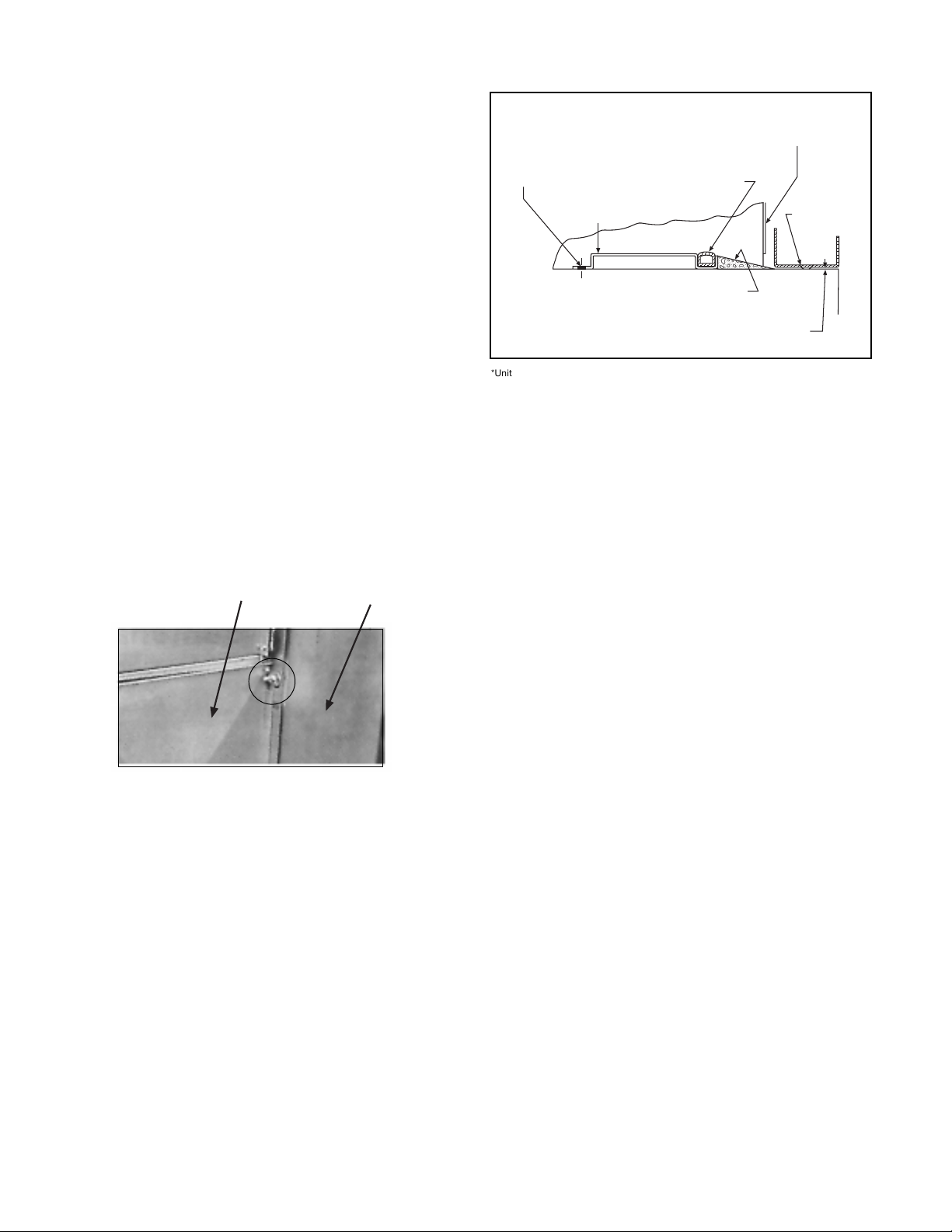
Figure 2. Cross Section Detail of Bottom of
Wall Sleeve & Intake
Fasten cross channel to floor
thru 1⁄4" holes with appropriate
fasteners (by others.)
7 fasteners - AZS/AZQ 24, 30
8 fasteners - AZS/AZQ 36, 42
9 fasteners - AZS/AZQ 44, 48, 54
Bottom of Wall Sleeve
Cross Channel
A "D" shaped seal is
provided at the bottom
rear of the Wall Sleeve
to provide a watertight
seal to the bottom of
the unit when installed.
Seal both ends and top of
Wall Sleeve to building,
watertight at rear flange.
Bottom channel
of Louver
3
⁄16"
Wall Sleeve Installation
General — The wall sleeve must be installed before the unit
can be placed. The wall sleeve measures 85", 96" or 108"
wide by 28" high and may be recessed into the wall up to
3
⁄8" in depth.* Consult the approved AAF submittal draw-
11
ings for the job to determine the proper amount of recess,
if any, and recommended wall opening size.
The wall sleeve is attached to the unit chassis (weld studs)
using 4-nuts and washers, see figure 1.
The AAF wall sleeve and louver design is based on a "wet
sleeve" concept. In brief, this means the design accommodates the penetration of some moisture into the rear section
of the wall sleeve with the provision being made for containment and disposal of this moisture to the outdoors.
It is necessary for that portion of the opening between the
wall sleeve and the louver to be completely enclosed by the
installer to prevent air and water leaks into the building.
*Unit may also be installed with full 28˝ deep cabinet projecting into the room.
Figure 1.
Recessed and Nonrecessed Applications
The installing contractor shall do the following:
1. Make sure there is a masonry lintel supporting the wall
above any masonry opening.
2. Frame and seal air- and watertight all openings not en-
closed by the wall sleeve.
3. Refer to relevant figures for details of required sealing:
Figure 2 for all applications.
Figures 3 and 4 for recessed wall sleeve applications.
Figures 5 and 6 for nonrecessed wall sleeve applications.
4. Seal watertight both ends and top of wall sleeve to building
at rear flange of wall sleeve.
5. Seal watertight bottom of wall sleeve at rear "D" seal to
building and pitch toward louver bottom channel. Also
fasten cross channel to floor through holes with fasteners
(by others). See Figure 2.
Chassis
Wall Sleeve
Seal watertight bottom of Wall Sleeve at rear "D" seal
to building and pitch toward bottom channel of louver
as shown.
*Unit may also be installed with the full 28" deep cabinet projecting into the room.
6. The louver must be installed with the drain notches
located at the bottom and the bird screen located on
the unit side. Openings between notches must be free
of mortar or other foreign material for water removal. Refer
to IM 449 for specific details regarding louver installation.
7. Apply rubber stripping or sealant material (by others)
across full length of wall sleeve splitters.
8. If the louver does not butt up against the wall sleeve:
a. Fabricate a horizontal air splitter from galvanized
steel, redwood or some other suitable weather resistant material. The width of the air splitters is determined
by the width of the wall opening. The depth of the air
splitters is determined by the distance between the
louver horizontal splitter and the wall sleeve splitters.
b. The horizontal air splitters should have a 1" diameter
drain hole approximately 6" from each end.
c. Install the horizontal air splitters by fastening to the
wall sleeve splitters.
d. Apply rubber stripping or sealant material (by
others) across full length of horizontal air splitters
to seal against louver.
9. Permanently seal any remaining air leaks so that, when
finished:
a. There is an airtight separation between the discharge
air and the return air of the condenser fan;
b. There are no air leaks around the perimeter of the wall
sleeve where it adjoins the wall.
Recessed Applications (See Figures 3 and 4)
The installing contractor shall do the following:
1. Place the wall sleeve into the wall opening and recess it
the amount shown on the approved AAF submittal drawings.
2. Level the wall sleeve horizontally and plumb the wall sleeve
vertically.
3. Fasten the wall sleeve securely in place using fasteners
through the two knockouts provided on each end.
4. Caulk or seal any space between the wall sleeve and the
wall on both the room side and the outdoor side.
IMPORTANT: Opening under Louver must be
free of foreign material for water removal.
Page 4 / IM 503-1
Page 5
CAUTION: Sleeves furnished for use with optional heated rear drain will have an electric cord installed along
the length of the wall sleeve splitter. Avoid screw penetration or drilling into this cord when
installing the horizontal air splitter. (Model AZS, AZQ Only)
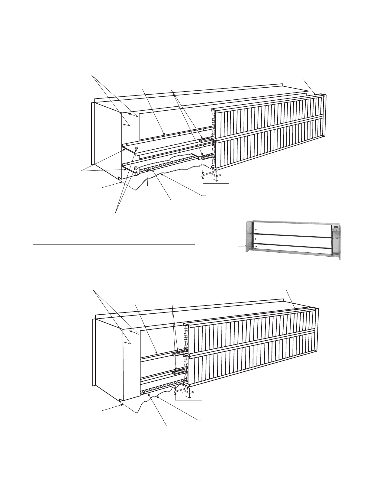
Figure 3. Rear View of Recessed Wall Sleeve With Horizontal Air Splitters
By Others. Wall Sleeve must
be sealed watertight at top and
both ends at location shown.
By Others. Seal Horizontal
Air Splitters to building at
both ends.
By Others. Seal both ends of
opening between Wall Sleeve
and Louver.
IMPORTANT NOTE:
By Others: Attach Horizontal Air Splitters to Wall Sleeve
Splitters as shown. Splitters to have 1" dia. drain hole
approx. 6" from each end.
Wall Sleeve Splitter(s)
(See Caution Above)
"D" Seal
By Others. Wall Sleeve must be sealed
watertight at bottom at location shown.
Refer to cross section detail of bottom
of Wall Sleeve and Louver.
(Figure 2.)
Seal Horizontal Air Splitter(s)
to Louver. (By Others)
3
⁄16" Under Intake must be free for water run-off. INTAKE MUST
STAND ON EMBOSSED FEET LOCATED ON BOTTOM.
By Others. Building must be sealed between Wall
Sleeve and under Louver for water run-off. Pitch
toward Louver.
Condenser discharge
Condenser inlet
Outdoor air inlet
By Others. Louver must be sealed
watertight at top and both ends.
Figure 4. Rear View of Recessed Wall Sleeve Without Horizontal Air Splitters.
By Others. Wall Sleeve must
be sealed watertight at top and
both ends at location shown.
By Others. Seal Horizontal
Air Splitters to building at
both ends.
Wall Sleeve Splitter(s)
(See Caution Above)
"D" Seal
By Others. Wall Sleeve must be sealed
watertight at bottom at location shown.
Refer to cross section detail of bottom
of Wall Sleeve and Louver.
(Figure 2.)
IMPORTANT NOTE: By Others. Seal
Louver to Wall Sleeve at top and bottom Wall Sleeve Splitters, and ends.
3
⁄16" Under Intake must be free for water run-off. INTAKE MUST
STAND ON EMBOSSED FEET LOCATED ON BOTTOM.
By Others. Building must be sealed between Wall
Sleeve and under Louver for water run-off. Pitch
toward Louver.
By Others. Louver must be sealed
watertight at top and both ends.
IM 503-1 / Page 5
Page 6

CAUTION: Sleeves furnished for use with optional heated rear drain will have an electric cord installed along
the length of the wall sleeve splitter. Avoid screw penetration or drilling into this cord when
installing the horizontal air splitter. (Model AZS, AZQ Only)
Figure 5. Rear View of Nonrecessed Wall Sleeve With Horizontal Air Splitters
By Others. Apply sealant (by others) to bottom edge of unit (not
shown) and to top flange and both end flanges of wall sleeve (as
shown.) This must provide a watertight seal to the wall of the
building.
By Others. Seal Horizontal
Air Splitters to building at
both ends.
By Others. Seal both ends of
opening between Wall Sleeve
and Louver.
IMPORTANT NOTE:
By Others: Attach Horizontal Air Splitters to Wall Sleeve
Splitters as shown. Splitters to have 1" dia. drain hole
approx. 6" from each end.
Wall Sleeve Splitter(s)
(See Caution Above)
Seal Horizontal Air Splitter(s)
to Louver.
"D" Seal
By Others. Wall Sleeve must be sealed
watertight at bottom at location shown.
Refer to cross section detail of bottom
of Wall Sleeve and Louver.
(Figure 2.)
3
⁄16" Under Intake must be free for water run-off. INTAKE MUST
STAND ON EMBOSSED FEET LOCATED ON BOTTOM.
By Others. Building must be sealed between Wall
Sleeve and under Louver for water run-off. Pitch
toward Louver.
Condenser discharge
Condenser inlet
Outdoor air inlet
By Others. Louver must be sealed
watertight at top and both ends.
Figure 6. Rear View of Nonrecessed Wall Sleeve Without Horizontal Air Splitters
By Others. Apply sealant (by others) to bottom edge of unit (not
shown) and to top flange and both end flanges of wall sleeve (as
shown.) This must provide a watertight seal to the wall of the
building.
By Others. Seal both ends of opening
between Wall Sleeve and Louver.
Wall Sleeve Splitter(s)
"D" Seal
By Others. Wall Sleeve must be sealed watertight at bottom at location
shown. Refer to cross section detail of bottom of Wall Sleeve and Louver.
(Figure 2.)
IMPORTANT NOTE: By Others. Seal
Louver to Wall Sleeve at top, Wall
Sleeve Splitters and ends.
3
⁄16" Under Intake must be free for water run-off. INTAKE MUST
STAND ON EMBOSSED FEET LOCATED ON BOTTOM.
By Others. Building must be sealed between Wall Sleeve and under
Louver for water run-off. Pitch toward Louver.
By Others. Louver must be sealed
watertight at top and both ends.
Page 6 / IM 503-1
Page 7

Figure 7.
Typical Wall Louver
Louver
Blade
Factory Mounted Bird Screen
Bird Screen
Fasteners
Frame
Optional Flanges
Splitter Lines Up With
Wall Sleeve Splitter
Detail of Notches
(Drain Holes)
Bottom
Flange
Demountable
Louver Section
Drain Notch
At Bottom
Information
Labels
Nonrecessed Applications (See Figures 5 and 6)
The installing contractor shall check the following before
proceeding:
The wall behind the unit should be smooth and plumb.
The seals on the rear of the unit will take up the small
irregularities of normal masonry construction.
Furring strips must be installed on irregular walls or walls
with mullions in order to provide a flush surface for the unit
to seal against.
Any moldings at the floor/wall line should be omitted
behind the unit.
The installing contractor shall do the following:
1. Apply sealant (by others) to bottom edge at rear of unit top
and both end flanges on rear of wall sleeve to provide
watertight seal to interior wall of building.
2. Level the wall sleeve horizontally, and plumb the wall
sleeve vertically.
3. Fasten the wall sleeve securely in place by:
a. Securing it to the floor through the two (2)
3
⁄8" diameter
holes in the turned out bottom flanges of the wall
sleeve at each end, and/or:
b. Securing it to the wall through the two (2)
3
⁄8"
diameter holes in the turned out vertical flanges of the
wall sleeve at each end.
4. a. Panel wall applications should have the wall opening sleeved
to prevent moisture from seeping into the wall interior.
b. If the panel wall is less than 2
1
⁄4" thick, the wall louver
should be installed flush to the interior wall and be
allowed to extend to the outside as required.
5. Seals on rear of unit must be compressed to provide a
watertight seal after installation is complete.
Louver Installation
The standard louver is an aluminum, vertical, divided blade
design complete with bird screen. This louver is also available
with flanges and/or with a heavy-duty exterior lattice grille.
1. Figure 7 shows a detail of a typical louver. Before installation, carefully examine the louver and note the location of
the bird screen and the notches (drain holes). The louver
must be installed with the notches at the bottom and the
bird screen toward the unit.
2. Measure the opening to be sure there is adequate clearance
for the louver around the sides. Observe the opening in
relation to the wall sleeve and unit. For proper unit operation,
the louver must be centered left to right and top to bottom
to the wall sleeve. If the louver is of such a dimension that it
extends above, below, or beyond the wall sleeve, then these
areas must be blocked off airtight (see Figure 8).
3. If the wall sleeve does not extend into the wall far enough
to meet the louver, field fabricated splitter(s) must be
provided. The splitter(s) need to extend far enough to
engage the louver in order to form a proper seal.
4. Check to see if the horizontal divider on the louver is the
Optional Factory Mounted
Exterior Grille
Mechanical Fasteners (Number Required
Varies With Size of Louver)
Figure 8.
Shaded area of louver must
be blocked off & made airand watertight, by installing contractor.
Exaggerated oversize
louver or wall opening.
Unit Wall
Sleeve
same height as the horizontal splitter of the wall sleeve.
The louver consists of a frame, which must be permanently
mounted in the wall, a demountable center louver section
to allow service access to the rear of the unit. To install the
louver in the opening, the demountable center section
must be in place. This will insure that the frame remains
square during installation.
6. Before installing the louver in the opening, place a heavy
bead of caulk along the top and two sides of the frame that
come in contact with the walls of the opening. Use a
flexible, waterproof caulk such as silicone.
7. Once the louver has been placed in the opening, further
mechanical fastening may be desired or required. Fasten
in a manner appropriate to the installation. Care must be
taken if fasteners are to be placed in the frame. If this is
necessary, remove the demountable center section by
removing the screws that hold it in place. Drill holes in the
desired locations and fasten with flat head screws. Be sure
these screws do not interfere with the reinstallation of the
demountable section. Shims must be placed between the
frame and the wall so it won't be distorted. After the frame
has been satisfactorily fastened, reinstall the demountable
center section and secure with fasteners provided.
Once the frame and louver assembly has been installed,
run a bead of caulk around the outside perimeter of the
frame to seal it watertight. Caution: Do not plug the weep
holes in the bottom of the louver.
Louvers With Flanges
1. If the louver is supplied with flanges, follow steps 1 through
6 above. Additionally, place a bead of caulk on the inside
of the top and side flanges that come in contact with the
building facade. Do not caulk the bottom flange.
2. Place the louver in the opening and push it tight against the
building. Fasten it to the exterior of the building using
appropriate fasteners for the installation.
3. Seal the top and two sides with waterproof caulk to make
it weathertight. Do not seal the bottom flange. To do so
may trap water behind the flange.
IM 503-1 / Page 7
Page 8

Electrical Connections
All field wiring should be in accordance with the National
Electric Code and applicable local codes.
Refer to the wiring diagram furnished with the unit to determine electrical connections required.
Refer to Figure 9 for stub-up locations. Refer to pages 12
through 14 for main power connections and field wired controls, if any.
Check nameplate to verify power supply is correct.
Whenever the electric stub-up is brought in through the
Figure 9. Wall Sleeve With Electric Stub-up From Bottom or Side.
floor within the confines of the wall sleeve and any portion of
the wall sleeve is recessed into the wall, the conduit must be
flush with the floor to permit installation of the wall sleeve.
Sufficient space must be left around the conduit to permit the
attachment of continuing conduit after the wall sleeve is
installed. For concrete slabs, it is recommended that this be
accomplished either by sleeving the conduit or by recessing
a junction box into the slab.
2.5/1.75" Dia. Knockout
3.0/2.0" Dia. Knockout
Wall Sleeve
Conduit (by others)
Rear edge of wall sleeve
2.5/1.75" Dia. Knockout
3.0/2.0" Dia. Knockout
Wall Sleeve
.875" Dia. Knockouts (3)
SW1-Main Power Nonfused “On-Off” Switch (AAF-HermanNelson)
Safety Precaution: Reverse this cover when unit is
removed from wall sleeve to cover opening in the
end of switch box.
Wall Sleeve Junction Box
5
/8" x 35/8" opening (for main power wiring from wall
sleeve to chassis). Field connection by others.
Control receptacle with plug-in disconnect (AAFHermanNelson). Leads are provided for wire nut
connection to all remote controls.
Stub-up from
bottom must be
confined in this area.
1
/4"
6
5"
51/2"
.875" Dia. Knockouts (3)
1
/2"
SW1-Main Power Nonfused “On-Off” Switch (AAF-HermanNelson)
Right End
Of Unit
Safety Precaution: Reverse this cover when unit is
removed from wall sleeve to cover opening in the
end of switch box.
Wall Sleeve Junction Box
Whenever the electric stub-up is brought in
through the floor within the confines of the wall
sleeve, and any portion of the wall sleeve is
recessed into the wall, the conduit must be flush
with the floor to permit installation of the wall
sleeve. Sufficient space must be left around the
conduit to permit the attachment of continuing
conduit after the wall sleeve is installed. For
concrete slabs, it is recommended that this be
accomplished either by sleeving the conduit or by
recessing a junction box into the slab.
Conduit (by others)
Rear edge of wall sleeve
Page 8 / IM 503-1
5
/8" x 35/8" opening (for main power wiring from wall
sleeve to chassis). Field connection by others.
16"
1"
9"
5"
Control receptacle with plug-in disconnect (AAFHermanNelson). Leads are provided for wire nut
connection to all remote controls.
Stub-up through side must be confined to this
area: cut in field. Opening must be carefully
prepared and gasketed for air tightness.
Right End
Of Unit
Page 9

Note: These are general instructions. Refer to the AAFHermanNelson submittal drawings for specific dimensions,
unit arrangement, stub-up locations, recommended wall
opening size, etc.
Unit Placement
Before Moving Unit Up To Wall Opening:
1. Confirm unit is correct for the location.
2. Complete the installation of the wall sleeve and air intake
louver in accordance with the instructions on pages 4
through 9.
3. For nonrecessed applications, inspect the field applied
elastic tape to make sure it will seal tightly to prevent air
leaks after unit is installed.
4. Check room air and condenser fan bearings to be sure they
are secure (Figures 10 and 12).
5. Check room air and condenser fan shaft coupling setscrews to be sure they are tightened securely to both
motor shaft and fan shaft.
6. Rotate the room air and condenser fans to be sure they
rotate freely and quietly.
7 Check fan wheel setscrews for tightness.
8. Remove any debris from inside the unit.
Setting the Unit:
Slide the unit up to the wall sleeve aligning the four threaded
studs (Figure 13) on the wall sleeve with the holes on each end
of the unit. Sliding of the unit to the wall can be made easier
with the assistance of Caster Kit P/N - 105629001. A piece of
cardboard placed under the unit will make this job easier and
prevent marring the floor. (Do not leave cardboard under unit
after installation.) The wall sleeve mounting studs should slide
through the holes in the unit. Place the washers over the
threaded studs and tighten the mounting nuts. Do not draw
the nuts up as tight as possible as they may distort the unit and
loosen the caulking and wall sleeve from their position. If an
adapter collar is used, make sure that the unit, adapter collar
and wall sleeve all line up properly.
Figure 10.
ROOM AIR FAN
SHAFT BEARING
OIL CUP
Figure 11.
Oil Here
Caution:
Failure to follow these instructions may rack the
unit which can cause the fan or unit to vibrate
noisily on startup and appear to be in need of fan
balancing. For quiet, smooth unit operation it is
important that the unit be square, level and the
base solidly supported by the floor, using shims
where necessary due to uneven construction in
order to prevent distortion of the cabinet. It is
essential to keep unit level.
Defrost Condenser Drain Piping
It is strongly recommended that the condensate from the
heating defrost cycle be disposed of into a building condensate drain. See Figure 14, page 10 for details. If a building
condensate drain is not used, and the drain line is exposed to
freezing temperatures, adequate freeze protection must be
furnished.
Oiling
Do not attempt to operate the unit fans until the room air fan
shaft bearing has been oiled. Use a high grade SAE 20 or 30
nondetergent oil. A few drops are sufficient. Do not over oil.
Refer to Figure 10 for oil point. The fan motor does not require
oiling until after one year of operation (Figure 11).
Condenser motor and fan shaft bearings are permanently
lubricated.
Figure 12.
Figure 13.
CONDENSER
FAN SHAFT
BEARING
IM 503-1 / Page 9
Page 10

Piping Stub-up Details, 6" End Panel
Piping Stub-up Within Cabinet
Unit End Compartment
A
1
11
⁄
Wall Line
Caution: Space available in left end
compartment for piping stub-up.
Stub-up including unions and shutoff
valves must disconnect below floor
line for unit installation and removal.
2
1
103⁄
4
Left End
of unit
(Less end panel)
Piping Stub-up Within 6" End Panel
Unit End Compartment
1
Wall Line
Space available at left end of unit
for piping stub-up when 6" end
panel is used.
B
Hot Water Coil Piping Arrangements (see Note 12)
4
Left End of unit
(Less end panel)
End Panel 6"
Application and Dimension
6
All dimensions in inches
Piping Within Unit End Compartment Piping Outside Unit End Compartment
F&BP With End-of-Cycle Valve
3-Way Modulating Valve Control
F&BP With End-of-Cycle Valve
3-Way Modulating Valve Control
Page 10 / IM 503-1
Page 11

Coil Piping
Heating valve actuators should be mounted in an upright
position above the centerline of the valve body and should be
piped normally open to the coil. Modulating valve actuators
for hot water applications may be positioned above the valve
body a maximum of 75° from the vertical. For steam applications only, mount the modulating valve actuator above the
valve body at 45° from the vertical. Two-position, end-ofcycle (EOC) valves used with face and bypass damper controlled units may be positioned above the valve body a
maximum of 85° from the vertical. All control valves are
shipped loose to insure that no shipping damage occurs to the
piping or the coil connection stub from the weight of the valve
and to provide the installing contractor with maximum flexibility in making the field piping connections. Refer to AAFHermanNelson factory instruction sheet shipped with the unit
for port orientation and a piping schematic. Control valves
must be installed on the units in which they are shipped.
Indiscriminate mixing of valves among units can result in
valves not properly sized for the desired flow rate. Control
valves should be installed so that there is 2" minimum clearance to remove the actuator from the valve body. As a future
service consideration, provide unions for removal of the unit
coil and/or the control valve.
Notes:
1
Three-way control valve (AAF-HermanNelson)
2
Coil air vent (AAF-HermanNelson)
3
Coil drain (AAF-HermanNelson)
4
Shutoff valve (Others)
5
Balancing shutoff valve(s) (Others)
6
Supply
7
Return
8
Unions (Others)—Must disconect below floor line
9
Two-way, two-posiiton valve (AAF-HermanNelson)
10
Union: Half attached to coil, half attached to valve
11
Modulating control valve (AAF-HermanNelson)
12
All piping, fittings and unions by others (not AAFHermanNelson) except as noted
13
Check valve and pressure equalizing line (AAFHermanNelson)
14
Float and thermostaic steam trap (Others)
15
Supply and return coil connection and stub-up unions by
others
Steam Coil Piping Arrangements (see Note 12)
Piping Within Unit End Compartment Piping Outside Unit End Compartment
F&BP With End-of-Cycle Valve
F&BP With End-of-Cycle Valve
2-Way Modulating Valve Control
IM 503-1 / Page 11
Page 12

Pre-installation Checklist
¨ Lintel installed above wall louver to support masonry
wall
¨ Bird screen on wall louver facing toward room interior
¨ Embossments of wall louver at bottom and free for
drainage.
¨ Wall sleeved to prevent moisture seepage into wall
¨ Free opening under wall louver clear for water run-out
¨ Wall louver anchored and sealed against air and water
leaks
¨ Horizontal air splitter between wall sleeve and louver
(if required)
¨ Wall sleeve anchored and sealed against air or water leaks
¨ Shipping brace on condenser fan shaft removed
¨ Condenser fan shaft coupling and bearing secure
¨ Room air in shaft coupling and bearing secure
¨ All fan wheels rotate freely and quietly
¨ Any debris removed from inside unit
¨ Unit identified and correct for location
¨ Access space provided for maintenance, service and
unit removal
¨ Shipping carton saved for use later to protect unit
¨ Check unit nameplate to verify that power supply is
correct
Post-installation Checklist
¨ Unit securely fastened to wall sleeve
¨ Electrical hook-up complete; power, control, wall
thermostat (if applicable) in accordance with unit wiring
diagrams.
¨ Air filter clean and in place
¨ All access and end panels in place and protective
covering removed
¨ Room air fan shaft bearing oiled
¨ Unit square and level and running smoothly and quietly
¨ No air infiltration
¨ Paint nicks and scratches touched up (as required)
¨ Shipping carton replaced over unit for protection
Page 12 / IM 503-1
Page 13

Field Wiring Controls, Maximum Outdoor Air Unit
Wall Sleeve Junction Box - Right End
YEL
36
37
BRN
Factory Wiring
Furnished
Only As Required
BLK
WHT
RED
GRN
ORG
BLU
PNK
GRY
904A
910
911
For Further
Information
See Appropriate Field
Wiring Detail
Humidistat
Wiring
Day/Night Changeover Control
(Stand-Alone Units Only)
Control
Receptacle
In Wall Sleeve
Junction Box
YEL
36
37
BRN
BLK
WHT
RED
GRN
ORG
BLU
PNK
GRY
Day/Night
Changeover
(4VA Inrush)
Energize To
Put Unit In
Night
Mode
Control Receptacle
Field Connection
By Others (Not AAF-HermanNelson)
To The Load Side Of SW-1.
[(2) Wires Per Pole If Unit
Has Electric Heat]
SW-1 - - Main Power “On - Off” Switch
Master/Slave
(Stand-Alone Units Only)
Attach Wires From Unit To Unit In Daisy
Chain Fashion, In Any Order. See Chart 1
For Correct Wire/Line Voltage Combination.
Shields Are To Be Grounded In Each Unit.
YEL
36
37
BRN
BLK
WHT
RED
GRN
ORG
BLU
PNK
GRY
Control Receptacle
In Wall Sleeve
Junction Box
First Unit
BLU
PNK
GRY
Ground
1
2
3
SW-1
L1
Main Power Supply
(Omit L3 For Single
L2
Phase Applications)
L3
Field Wiring
Network Wiring
(Network Units Only)
Attach Wires From Unit To Unit In Daisy
Chain Fashion. In Any Order, See Chart 2
For Correct Wire/Line Voltage Combination.
Shields Are To Be Grounded In Each Unit.
YEL
36
37
BRN
BLK
WHT
RED
GRN
ORG
BLU
PNK
GRY
Control Receptacle
In Wall Sleeve
Junction Box
First Unit
BLU
PNK
GRY
Ventilation Lockout Control
(Stand-Alone Units Only)
YEL
36
37
BRN
Control
Receptacle
In Wall Sleeve
Junction Box
BLK
WHT
RED
GRN
ORG
BLU
PNK
GRY
Exhaust Fan Interlock
YEL
36
37
BRN
Control
Receptacle
In Wall Sleeve
Junction Box
BLK
WHT
RED
GRN
ORG
BLU
PNK
GRY
Vent Lockout
(4VA Inrush)
Energize
To Close The
Outdoor Air Damper
Exhaust Fan
Interlock
(4VA Inrush)
Energize To Open
Outdoor Air
Damper
Chart 1
Belden or
Equivalent
Control Receptacle
In Wall Sleeve
Junction Box
Additional Unit
BLU
PNK
GRY
Control Receptacle In
Wall Sleeve Junction
Box Last Unit
Wire Mfg.
2-Wire 8761 9341
Mfg.’s Wire No.
0-300V 301-600V
Chart 2
Belden or
Equivalent
Control Receptacle
In Wall Sleeve
Junction Box
Additional Unit
BLU
PNK
GRY
Control Receptacle In
Wall Sleeve Junction
Box Last Unit
Wire Mfg.
2-Wire 8761 9341
To Local
Master Panel
Mfg.’s Wire No.
0-300V 301-600V
Pneumatic Day/Night ChangeoverControl
(Stand-Alone Units Only)
YEL
36
Control
Receptacle
In Wall Sleeve
Junction Box
37
BRN
Pneumatic/Electric
BLK
Switch.
WHT
Close Contacts
To Put Unit In
RED
Night Mode. (24VAC,
GRN
Class II, 1 AMP)
ORG
BLU
PNK
GRY
IM 503-1 / Page 13
Page 14

Wall Mounted Room Air Sensors
Control
Receptacle
in wall sleeve
junction box
Control
Receptacle
in wall sleeve
junction box
Sensor
Terminal
Board
Sensor
Terminal
Board
Wall Sensor
3.30
(Ref.)
4.87
3.06
(Ref.)
1.50
Wall Sensor With Tenant Override
3.30
(Ref.)
4.87
3.06
(Ref.)
1.50
Transparent
Lens For
Green LED
Transparent
Lens For
Green LED
Tenant
Override
Switch
Main Power To 0 To 301 To
Unit (Volts) 300V 600V
Shielded Wire Manufacturer
Manufacturer Wire No.
Belden
or Equiv.
Dearborn 4-Wire – 1061804
Do not install sensor wires in same conduit
with power wiring. Ground shield in wall
sleeve junction box.
Main Power To 0 To 301 To
Unit (Volts) 300V 600V
Shielded Wire Manufacturer
Manufacturer Wire No.
Belden
or Equiv.
Dearborn 4-Wire – 1061804
Do not install sensor wires in same conduit
with power wiring. Ground shield in wall
sleeve junction box.
4-Wire 8729 –
4-Wire 8729 –
Control
Receptacle
in wall sleeve
junction box
Control
Receptacle
in wall sleeve
junction box
Wall Sensor With Tenant Override & Setpoint Adjustment
3.30
Sensor
Terminal
Board
1.50
3.06
4.87
(Ref.)
(Ref.)
Setpoint Adjust
Potentiometer
Transparent
Lens For
Green LED
Tenant
Override
Switch
Do not install sensor wires in same conduit
with power wiring. Ground shield in wall
sleeve junction box.
Wall Sensor With Setpoint Adjustment
3.30
(Ref.)
Transparent
Lens For
Green LED
4.87
3.06
(Ref.)
Sensor
Terminal
Board
1.50
Setpoint Adjust
Potentiometer
Do not install sensor wires in same conduit
with power wiring. Ground shield in wall
sleeve junction box.
Main Power To 0 To 301 To
Unit (Volts) 300V 600V
Shielded Wire Manufacturer
Manufacturer Wire No.
Belden
or Equiv.
Dearborn 4-Wire – 1061804
Main Power To 0 To 301 To
Unit (Volts) 300V 600V
Shielded Wire Manufacturer
Manufacturer Wire No.
Belden
or Equiv.
Dearborn 4-Wire – 1061804
4-Wire 8729 –
4-Wire 8729 –
IM 503-1 / Page 14
Page 15

End Panel Assembly
The final step of unit installation is attaching the end panels.
End panels are required unless the unit has adjoining matching cabinets.
1. Refer to Figure 15 for 1 " thick end panel. Attach two (2)
Tinnerman nuts to the top edge of the end panel and two
(2) to the bottom end of the unit. Align the end panel with
the front and top edges of the unit. Attach end panel to the
unit using four (4)
2. Refer to Figure 15 for 6" thick end panel.
a. Position bracket (YC1934) on wall so angle is 5" from
end of unit and near bottom.
Figure 15. 1" End Panel
5
⁄32" hex socket head fasteners provided.
b. Mark and drill required hole for device to fasten bracket
to wall (not included).
c. Attach bracket to wall.
d. Attach two (2) Tinnerman nuts to the top edge of the end
panel and one (1) to the bottom front of the end frame.
e. Align the end panel with the front and top edges of the unit.
5
⁄
Attach end panel to the unit using three (3)
" hex socket
32
head fasteners provided. Bracket should prevent move-
ment of panel toward the unit when pressure is applied to
the end panel.
Figure 15. 6" End Panel
End of Unit
Bracket
YC 1934
IM 503-1 / Page 15
Page 16

Product Warranty
AAF-McQuay Incorporated, hereinafter referred to as the
"Company," warrants that it will provide, at the Company's
option, either free replacement parts or free repair of component parts in the event any product manufactured by the
Company and used in the United States and Canada proves
defective in material or workmanship within twelve (12) months
from initial start-up or eighteen (18) months from the date
shipped by the Company, whichever comes first. For additional consideration, the Company warrants that for four (4)
years following the initial warranty period it will provide, at the
Company's option, free replacement parts for the motorcompressor, or, free replacement for any integral component
of the motor-compressor which proves defective in material
or workmanship. For an additional consideration, the Company warrants that for nine (9) years following the initial
warranty period it will provide free replacement of the heat
exchanger in gas-fired or oil-fired furnaces which proves
defective in material and workmanship. (Extended warranties
for motor-compressors and heat exchangers are not applicable unless separately purchased.)
To obtain assistance under this parts warranty, extended
motor-compressor warranty, or extended heat exchanger
warranty, simply contact the selling agency. To obtain information or to gain factory help for AAF-McQuay, and
HermanNelson brandnames, contact AAF-McQuay Incorporated, Warranty Claims Department, 4900 Technology Park
Boulevard, Auburn, New York 13021-9030, telephone (315)253-2771.
This warranty constitutes the buyer's sole remedy. It is
given In lieu of all other warranties. There is no implied
warranty merchantability or fitness for a particular purpose. In no event and under no circumstances shall the
Company be liable for incidental or consequential damages, whether the theory be breach of this or any other
warranty, negligence or strict tort.
This parts warranty and the optional extended warranties
extend only to the original user. Of course, abuse, misuse, or
alteration of the product in any manner voids the Company's
warranty obligation. Neither the parts or extended warranty
obligates the Company to pay any labor or service costs for
removing or replacing parts, or any shipping charges. Refrigerants, fluids, oils, and expendable items such as filters are
not covered by this warranty.
The extended warranties apply only to integral components of the motor-compressor or heat exchanger, not to
refrigerant controls, electrical controls, or mechanical controls, or to failures caused by failure of those controls.
Attached to this warranty is a requirement for equipment
containing motor-compressors and/or furnaces to report startup information. The registration form accompanying the product must be completed and returned to the Company within
ten (10) days of original equipment start-up. If that is not done,
the date of shipment shall be presumed to be the date of startup and the warranty shall expire twelve (12) months from that
date.
No person (including any agent, salesman, dealer or distributor) has authority to expand the Company's obligation
beyond the terms of this express warranty, or to state that the
performance of the product is other than that published by the
Company.
AAF-HermanNelson
4900 Technology Park Boulevard, Auburn, NY 13021-9030 USA, (315) 253-2771
Printed on recycled paper containing at least 10% post-consumer material.
©1999 AAF-HermanNelson
Page 16 / IM 503-1 (Rev. 6/99)
 Loading...