

Page 1
Installation Manual IM 1 167
Group: Chillers
Pathfinder® Air Cooled Chillers
Part Number:
Date: July 23, 2012
Model AWS-B (Rev 0B) • Standard, High, & Premium Efficiencies
Includes models with VFD and models with Remote Evaporator
170 to 550 tons • 600 to 1930 kW • R-134a • 60Hz
IM 1167
REV
00
© 2012 McQuay International
Page 2
Introduction. . . . . . . . . . . . . . . . . . . . . . . . . . . . . . . . 3
Modbus
Installation and Startup . . . . . . . . . . . . . . . . . . . . . . 4
Clearance Requirements . . . . . . . . . . . . . . . . . 5
Chilled Water Piping. . . . . . . . . . . . . . . . . . . . 10
Physical Data (non-VFD) . . . . . . . . . . . . . . . . . . . . 15
Physical Data (VFD) . . . . . . . . . . . . . . . . . . . . . . . . 30
Lifting & Mounting Weights (I-P Units). . . . . . . . . 39
Lifting & Mounting Weights (SI Units) . . . . . . . . . 41
Lifting & Mounting Locations - Index of Drawings 43
Dimensions (non-VFD). . . . . . . . . . . . . . . . . . . . . . 44
Dimensions (VFD). . . . . . . . . . . . . . . . . . . . . . . . . . 50
Isolator Locations and Kit Numbers. . . . . . . . . . . 55
Electrical Data. . . . . . . . . . . . . . . . . . . . . . . . . . . . . 64
Wiring Diagram. . . . . . . . . . . . . . . . . . . . . . . . . . . . 65
Multipoint Electrical Data (non-VFD) . . . . . . . . . . 67
Multipoint Field Wiring Data (non-VFD) . . . . . . . . 78
Terminal Amps (non-VFD) (single/multi-point) . . 88
Single-point Electrical Data (non-VFD) . . . . . . . . 92
Single-point Field Wiring Data (non-VFD). . . . . . 97
Multipoint Electrical Data (VFD). . . . . . . . . . . . . 101
Multipoint Field Wiring Data (VFD) . . . . . . . . . . 104
Terminal Amps (VFD) (single- and multi-point) 105
Single-point Electrical Data (VFD) . . . . . . . . . . . 106
Single-point Field Wiring Data (VFD). . . . . . . . . 107
Pressure Drop Data. . . . . . . . . . . . . . . . . . . . . . . 108
Remote Evaporators. . . . . . . . . . . . . . . . . . . . . . 115
Remote Evaporator Refrigerant Piping. . . . 116
Remote Evaporator Dimensions . . . . . . . . . . . . 123
Remote Evaporator Unit Dimensions . . . . . . . . 126
Remote Evaporator Lifting & Mounting Weights 152
Remote Evaporator Isolators. . . . . . . . . . . . . . . 154
Remote Evaporator Lifting & Mounting Locations 158
Remote Evaporator Physical Data. . . . . . . . . . . 166
Troubleshooting Chart . . . . . . . . . . . . . . . . . . . . 181
Hazard Identification
DANGER
Dangers indicate a hazardous situation which will result in death or serious injury if not avoided.
WARNING
Warnings indicate potentially hazardous situations, which can result in property damage, severe personal injury, or death if not
avoided.
CAUTION
Cautions indicate potentially hazardous situations, which can result in personal injury or equipment damage if not avoided.
Document: IM 1167
Issue Date: July 23, 2012
Revision Date: -Replaces: NEW
©2012 McQuay International. Illustrations and data cover the McQuay International product at the time of publicat ion and we reserve the right to make change s in design
and construction at anytime without notice. ™® The following are trademarks or register ed tradema rks of their r espective comp ani es: BACnet from ASHRAE; LONMARK ,
LonTalk, LONWORKS, and the LONMARK logo are managed, granted and used by LONMARK International under a license granted by Echelon Corporation; ElectroFin
from AST ElectroFin Inc.; Modbus from Schneider Electric; FanTrol, MicroTech III, Open Choices, and SpeedTrol from McQuay International
2 IM 1122-2
Page 3
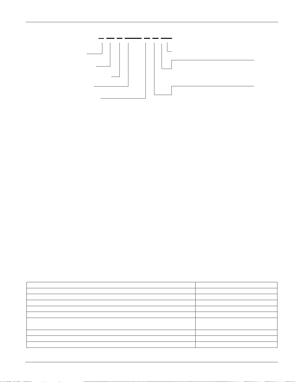
Introduction
S = Standard Efficiency
H = High Efficiency
A
W S XXX B D SE
Air-Cooled
World Product
Screw Compressor
Nominal Tons
D = Dual Compressor
Design Vintage
T = Triple Compressor
P = Premium Efficiency
E = Standard Packaged
M = Remote Evaporator
Figure 1: Model Nomenclature
General Description
Daikin McQuay Pathfinder™ air-cooled chillers are complete,
self-contained chillers that include the latest in engineered
components arranged to provide a compact and efficient unit.
Each unit is completely assembled, factory wired, evacuated,
charged, tested and comes complete and ready for installation.
Each of two circuits consists of an air-cooled condenser
section with an integral subcooler section, a semi-hermetic,
single-screw compressor with starter, a multi-circuit, shelland-tube, direct expansion evaporator, an economizer and
complete refrigerant piping. Each compressor has an
independent refrigeration circuit. Liquid line components
included are a manual liquid line shutoff valve, charging port,
filter-drier, sight-glass/moisture indicator, and electronic
expansion valve. A combination discharge check and shutoff
valve is included and a compressor suction shutoff valve is
optional. Other features include compressor heaters,
evaporator heaters for freeze protection, automatic, one-time
pumpdown of each refrigerant circuit upon circuit shutdown,
and an advanced fully integrated microprocessor control
system.
Pathfinder units are available as standard efficiency (BDS) or
high efficiency (BDH) or premium efficiency (BDP). A high
ambient option is required for operation in ambient
temperatures above 100F (37.8C) and up to 125F (51.7C)
and when the VFD low ambient option is selected.
Introduction
Information on the operation of the unit MicroTech
controller is in the OM 1123 manual, available on
www.daikinmcquay.com.
Remote Evaporator Models
For enhanced application flexibility, AWS non-VFDand VFD
models are also available as remote evaporator models.
Information on remote evaporator units can be found
beginning on page 117.
Inspection
When the equipment is received, carefully check all items
against the bill of lading to verify for a complete shipment.
Check all units for damage upon arrival. All shipping damage
must be reported to the carrier and a claim must be filed with
the carrier. Check the unit’s serial plate before unloading the
unit to be sure that it agrees with the power supply available.
Physical damage to a unit after shipment is not McQuay
International’s responsibility.
Note: Unit shipping and operating weights are shown in the
Physical Data Tables beginning on page 15.
III
Table 1: Operating Limits
Maximum standby ambient temperature 130°F (55°C)
Maximum operating ambient temperature 100°F (37.8°C)
with optional high ambient package (see detailed information in Cat 600) 125°F (52°C)
Minimum operating ambient temperature (standard control) 35°F (2°C)
Minimum operating ambient temperature (with optional low-ambient control) 0°F (-18°C)
Leaving chilled water temperature 40°F to 60°F (4.4°C to 15.6°C)
Leaving chilled fluid temperatures (with anti-freeze) - Unloading is not permitted with fluid leaving
temperatures below 30°F (-1°C). 20°F to 60°F (-7°C to 16°C)
Operating chilled water delta-T range 6 to 18°F (-14 to -8°C)
Maximum evaporator operating inlet fluid temperature 76°F (24°C)
Maximum evaporator non-operating inlet fluid temperature 100°F (38°C)
IM 1167 3
Page 4
Installation and Startup
Installation and Startup
Installation and maintenance are to be performed only by
qualified personnel who are familiar with local codes and
regulations, and experienced with this type of equipment.
WARNING
Sharp edges and coil surfaces are a potential injury hazard.
Avoid contact with them.
Start-up by McQuay Factory Service is included on all
Pathfinder units sold for installation within the U.S. and
Canada and must be performed by them to initiate the standard
Limited Product Warranty. Start-up by any party other than
McQuay Factory Service or a McQuay Authorized Service
Representative will void the Limited Product Warranty. Twoweek prior notification of start-up is required. The contractor
should obtain a copy of the Start-up Scheduled Request Form
from the sales representative or from the nearest McQuay
Factory Service office.
WARNING
Escaping refrigerant can displace air and cause suffocation.
Immediately evacuate and ventilate the equipment area. If the
unit is damaged, follow Environmental Protection Agency
(EPA) requirements. Do not expose sparks, arcing equipment,
open flame or other ignition source to the refrigerant.
For pad-mounted units, it is recommended that the unit be
raised a few inches with suitable supports such as neoprene
waffle vibration pads, located at least under the mounting
locations. This will allow water to drain from under the unit
and facilitate cleaning under it.
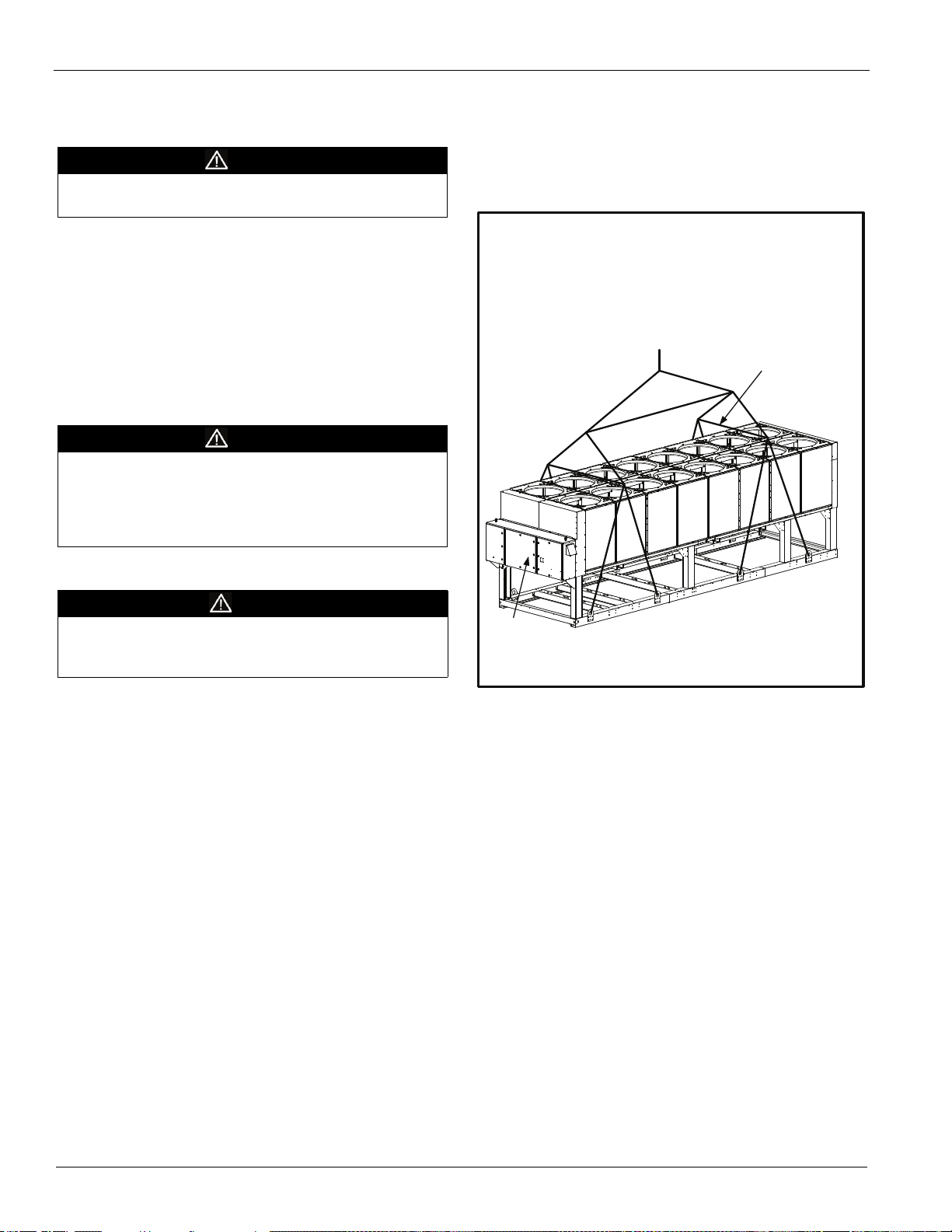
Figure 2: Required Lifting Method
Handling
DANGER
Improper lifting or moving of a unit can result in property
damage, severe personal injury or death. Follow rigging and
moving instructions carefully.
Avoid rough handling shock due to impact or dropping the
unit. Do not push or pull the unit. Never allow any part of the
unit to fall during unloading or moving, as this can result in
serious damage.
To lift the unit, lifting tabs with 3" (76 mm) diameter holes are
provided on the base of the unit. All lifting holes must be used
when lifting the unit. Spreader bars and cables should be
arranged to prevent damage to the condenser coils or unit
cabinet (see Figure 2).
Location
Locate the unit outdoors and carefully to provide proper
airflow to the condenser. (SeeFigure 4, page 5 for required
clearances.)Using less clearance than shown in Figure 4can
cause discharge air recirculation to the condenser and could
have a significant detrimental effect on unit performance.
Due to the shape of the condenser coils on the Pathfinder
chillers, it is recommended that the unit be oriented so that
prevailing winds blow parallel to the unit length, thus
minimizing the wind effect on condensing pressure and
performance. If low ambient temperature operation is
expected, optional louvers should be installed if the unit has no
protection against prevailing winds.
4 IM 1167
NOTES:
1. Unit with 8 lifting points illustrated above; the number of
condenser sections, fans, and lifting points can vary from
this diagram.see lifting/mounting drawings beginning on
page page 44 to identfy the number of lifting points for a
specific unit.
2. All rigging points must be used. See weights at lifting
points beginning on page 39 for each specific size unit.
3. Crosswise and lengthwise spreader bars must be used to
avoid damage to unit.
Service Access
Compressors, filter-driers, and manual liquid line shutoff
valves are accessible on each side or end of the unit. The
evaporator heater is located on the barrel.
The control panels are located on the end of the chiller. The
left-hand control box contains the unit and circuit
microprocessors as well as transformers, fuses and terminal.
The right-hand panel contains a circuit breaker. A minimum of
four feet of clearance is required in front of the panels. The
side clearance required for airflow provides sufficient service
clearance.
Page 5
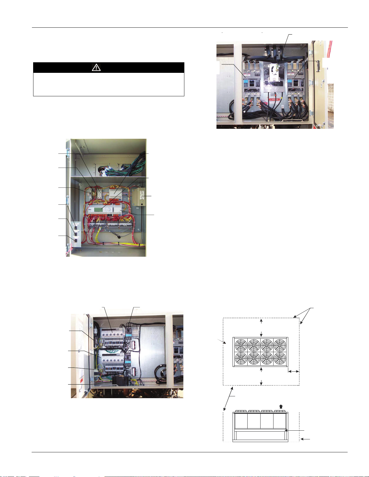
On all Pathfinder units, the condenser fans and motors can be
Fan Contactors, 1 per Fan
Circuit #1
Cir# 1, Fan Circuit Breake
r
Fan Contactors
1
p
er Fan, Circuit #2
Phase/Voltage
Monitor
120/24V
Transforme
r
Line/120V
Transformer
NOTES:
1. The Emergency Switch Relay de-energizes circuit #1 and #2 control power when activated,
causing an immediate compressor and fan shut
down. When ordered, the optional red emergency
button switch is located on the bottom front of the control panel door.
2. The control power transformer is located in the power panel adjacent to the control panel.
3. Additional extension (aka extension) modules are located elsewhere on the chiller.
Alarm & Limit
Extension
Module
MicroTech III
Main
Controller
Optional
115V
Outlet
Cir #1 & #2
Fan Control
Extension
Module
Controller
Fuse
Emergency
Switch
Relay
Control
Circuit
Breaker
Unit On/Off
Switch
Circuit #1
Pumpdown
Switch
Circuit #2
Pumpdown
Switch
g, ,g
Compressor #1
Circuit Breaker
Compressor #2
Circuit Breake
r
5ft (1.5 m)
if open fence or 50% open wall
if solid wall (see note 3 for pit )
5ft (1 .5m)
if open fence or 50% open wall
if solid wall (see note 3 for pit)
No obstructions.
Recommended area
required for unit
operation, air flow
and maintenance
access.
3ft (1m) for service
Se e Note 5
Wall or
Fence
Air Flo
w
No obstructions allowedabove unit at any heightSee notes 2 &
4
concerning wall
height at unit sides.
6ft (1 .8m)
6ft (1.8 m)
4ft (1.2 m)
For electric
panel access
removed from the top of the unit. The complete fan/motor
assembly can be removed for service. The fan blade must be
removed for access to wiring terminals at the top of the motor.
DANGER
Disconnect, lockout and tag all power to the unit before
servicing condenser fan motors or compressors. Failure to do
so can cause bodily injury or death.
Do not block access to the sides or ends of the unit with piping
or conduit. These areas must be open for service access. Do
not block access to the control panels with field-mounted
disconnect switches.
Installation and Startup
Figure 3: Control and Power Panel Component Location
Clearance Requirements
Notes:
1
Minimum side clearance between two units is 12 feet
(3.7 meters).
2 Unit must not be installed in a pit or enclosure that is
deeper or taller than the height of the unit unless extra
clearance is provided per note 4.
3 Minimum clearance on each side is 8 feet (2.4 meters)
when installed in a pit no deeper than the unit height.
4 Minimum side clearance to a side wall or building taller
than the unit height is 6 feet (1.8 meters), provided no
solid wall above 6 feet (1.8 meters) is closer than 12 feet
(3.7 meters) to the opposite side of the unit.
5 Do not mount electrical conduits where they can block
service access to compressor controls, refrigerant driers
or valves.
6 There must be no obstruction of the fan discharge.
7 Field installed switches must not interfere with service
access or airflow.
Figure 4: Clearance Requirements
IM 1167 5
Page 6
Installation and Startup
AWS PACKAGE CHILLER
331994701 REV. 0D
CHARGING
VALV E
LIQUID
TUBING
BALL
VALVE
CHARGING
VALV E
SOLENOID
VALVE
FILTER
DRYER
SOLENOID
VALV E
(OPTIONAL)
SIGHT
GLASS
EXPANSION
VALVE
WATER I N
WATER O UT
DX EVAPORATOR
SUCTION
TUBING
OIL PRESS.
TRANSDUCER
WITH SCHRADER
VALV E
DISCHARGE
TUBING
AIR
FLOW
AIR
FLOW
CONDENSER
ASSEMBLY
F3/F4
COMPRESSOR
RELIEF
VALV E
SUCTION
TEMP. SENSOR
SUCTION
TRANSDUCER
DISCHARGE
TEMP. SENSOR
(WOE)
TEMP. SENSOR
(WIE)
TEMP. SENSOR
OUTSIDE AIR
TEMPERATURE
(WAA)
SCHRADER
VALVE
SCHRADER
VALVE
SHUT-OFF
VALV E
BUTTERFLY
VALVE
(OPTIONAL)
RELIEF
VALV E
DISCHARGE
TRANSDUCER
SCHRADER
VALV E
STRAINER
BALL
VALVE
LIQUID
INJECTION
TUBING
SCHRADER
VALVE
(HEADER)
SCHRADER
VALV E
CHARGING
VALV E
Note: Provide 20-mesh strainer
at evaporator inlet
AWS PACKAGE CHILLER
WITH ECONOMIZER
331994701 REV. 0D
CHARGING
VALV E
LIQUID
TUBING
BALL
VALV E
ECONOMIZER
ECONOMIZER FLASH GAS TO COMPRESSOR INTERSTAGE
LIQUID
INJECTION
TUBING
FILTER
DRYER
SOLENOID
VALV E
(OPTIONAL)
SIGHT
GLASS
EXPANSION
VALV E
WATER I N
WATER OU T
DX EVAPORATOR
SUCTION
TUBING
OIL PRESS.
TRANSDUCER
WITH SCHRADER
VALV E
DISCHARGE
TUBING
AIR
FLOW
AIR
FLOW
CONDENSER
ASSEMBLY
F3/F4
COMPRESSOR
RELIEF
VALV E
SUCTION
TEMP. SENSOR
SUCTION
TRANSDUCER
DISCHARGE
TEMP.SENSOR
(WOE)
TEMP. SENSOR
(WIE)
TEMP. SENSOR
OUTSIDE AIR
TEMPERATURE
(WAA)
SCHRADER
VALV E
SCHRADER
VALV E
SCHRADER
VALV E
CHARGING
VALV E
SOLENOID
VALV E
TGE
EXPANSION
VALV E
SHUT-OFF
VALV E
CHECK
VALV E
CHECK
VALV E
BUTTERFLY
VALV E
(OPTIONAL)
RELIEF
VALV E
DISCHARGE
TRANSDUCER
BALL
VALV E
SCHRADER
VALV E
SOLENOID
VALV E
SCHRADER
VALV E
STRAINER
SCHRADER
VALV E
(HEADER)
VALV E
CHARGING
VALV E
Note: Provide20-mesh strainer
at evaporator inlet
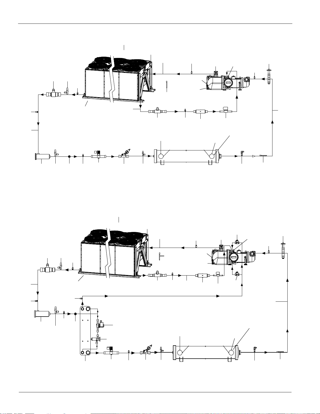
Figure 5: Refrigerant Diagram - All Standard Efficiency Models (one circuit shown of two or three possible circuits)
Figure 6: Refrigerant Diagram-All High and PremiumEfficiency Models (one circuit shown of two - three possible circuits)
6 IM 1167
Page 7
Installation and Startup
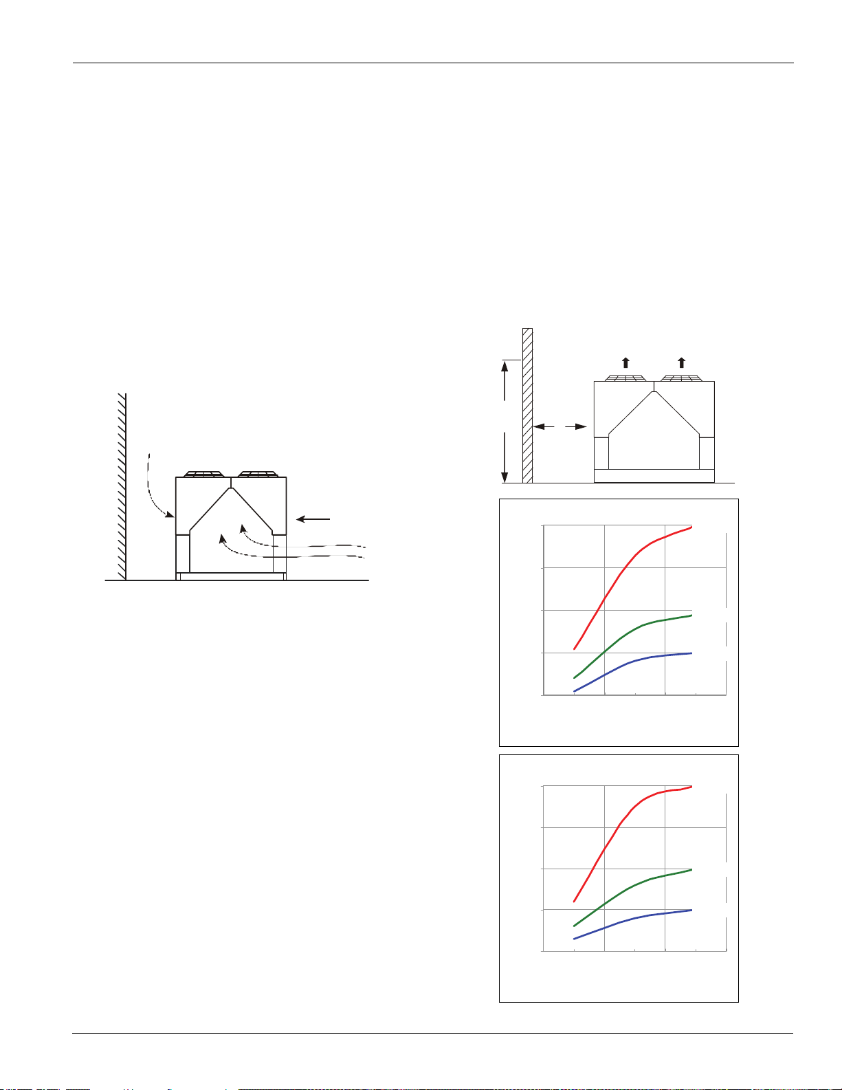
Building
Full Load Capacity Adjustment Factor
D=4 ft (1 .2m)
D=5 ft (1 .5m)
D=6 ft (1 .8m)
0.00
0.25
0.50
0.75
1.00
8
(2.4)
16
(4.8)
24
(7.2)
H - Height of W all or Building in ft. (m )
)
Full Load Power Adjustment Factor
D=4 ft (1 .2m)
D=5 ft (1 .5m)
D=6 ft (1 .8m)
0.00
0.50
1.00
1.50
2.00
8
(2.4)
16
(4.8)
24
(7.2)
H - Height of W all or Building in ft . (m)
Power Increase ( %)
H
D
Restricted Air Flow
The clearances required for design operation of Pathfinder aircooled chillers are described in the previous section.
Occasionally, these clearances cannot be maintained due to site
restrictions such as units being too close together or a fence or
wall restricting airflow, or both. Pathfinder chillers have
several features that may help mitigate the penalties
attributable to restricted airflow.
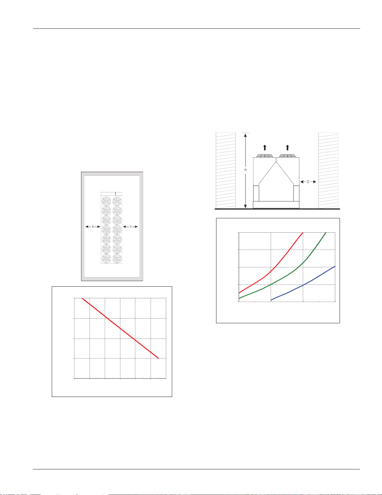
"The condenser section is "W" shaped, as shown below. This
allows inlet air for these coils to come in from both sides and
the bottom. All the coils in one "V" section serve one
compressor. Each compressor has its own independent
refrigerant circuit.
"The MicroTech III control is proactive in response to "offdesign conditions". In the case of single or compounded
influences restricting airflow to the unit, the microprocessor
will act to keep the unit running (at reduced capacity), rather
than allowing a shut-off on high discharge pressure.
Case 1: Building or Wall on One Side of One Unit
The existence of a screening wall or the wall of a building in
close proximity to an air-cooled chiller is common in both
rooftop and ground level applications. Hot air recirculation on
the coils adjoining the wall will increase compressor discharge
pressure, decreasing capacity and increasing power
consumption.
When close to a wall, it is desirable to place chillers on the
north or east side of them. It is also desirable to have
prevailing winds blowing parallel to the unit's long axis. The
worst case is to have wind blowing hot discharge air into the
wall.
Figure 7: Unit Adjacent to Wall - Adjustment Factors
Capacity Reduction (%
IM 1167 7
Page 8
Installation and Startup
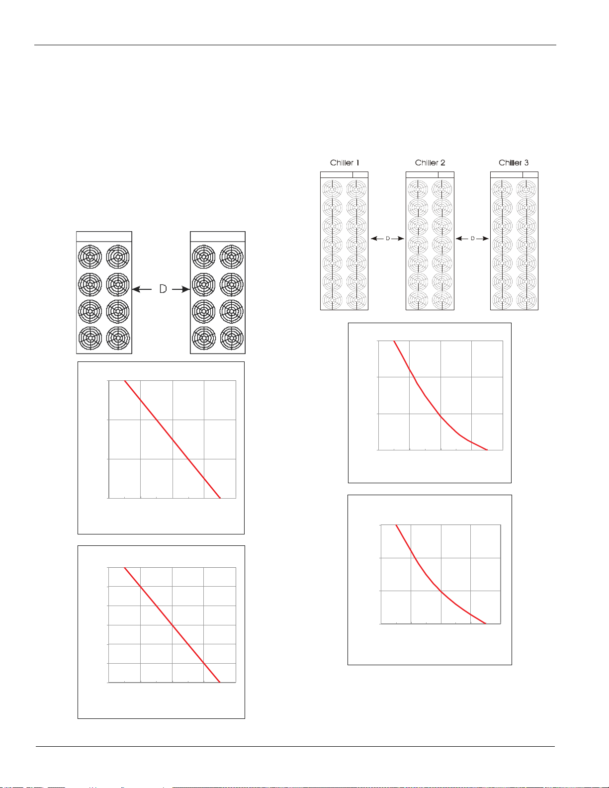
Full Load Capacity Adjustment Factor
0.00
0.50
1.00
1.50
6
(1.8)
8
(2.4)
10
(3.0)
12
(3.6)
Distance Between Units in ft. (m)
)
Full Load Power Adjustment Factor
0.00
0.50
1.00
1.50
2.00
2.50
3.00
6
(1.8)
8
(2.4)
10
(3.0)
12
(3.6)
Distance Between Units in ft. (m)
Power Increase (%)
Full Load Capacity Adjustment Factor
0.00
1.00
2.00
3.00
8
(2.4)
12
(3.6)
16
(4.8)
20
(6.1)
Distance Between Units in ft. (m)
)
Full Load Power Adjustment Factor
0.00
2.00
4.00
6.00
8
(2.4)12(3.6)16(4.8)20(6.1)
Distance Between Units in ft. (m)
Power Increase (%)
Case 2: Two Units Side By Side
Two or more units sited side by side are common. If spaced
closer than 12 feet (3.7 meters) it is necessary to adjust the
performance of each unit; circuits adjoining each other are
affected. If one of the two units also has a wall adjoining it, see
Case 1. Add the two adjustment factors together and apply to
the unit located between the wall and the other unit.
Mounting units end to end will not necessitate adjusting
performance.
Do not use pit or solid wall surrounds where the ambient air
temperature exceeds 105F (40C).
Figure 8: Two Units Side by Side - Adjustment Factors
Case 3: Three or More Units Side By Side
When three or more units are side by side, the outside chillers
(1 and 3 in this case) are influenced by the middle unit only on
their inside circuits. Their adjustment factors will be the same
as Case 2. All inside units (only number 2 in this case) are
influenced on both sides and must be adjusted by the factors
shown below.
Figure 9: Three or More Units - Adjustment Factor
Capacity Reduction (%
Capacity Reduction (%
8 IM 1167
Page 9
Installation and Startup
Wall Free Area vs Distance
0.00
2.00
4.00
6.00
8.00
0 1020304050
% Open Wall Area
D - Distance from Wall to Unit in Ft. (m)
Full Load Power Adjustment Factor
D= 6 ft ( 1.8 m)
D=8 ft (2.4m )
(3.1 m )
0.00
2.00
4.00
6.00
8.00
8
(2.4)
10
(3.1)
12
(3.7)
14
(4.3)
H - H e ig ht o f W all or B uild in g in ft. ( m)
Power Increas e (%)
Case 4: Open Screening Walls
Decorative screening walls are often used to help conceal a
unit either on grade or on a rooftop. Design these walls such
that the combination of their open area and distance from the
unit do not require performance adjustment. It is assumed that
the wall height is equal to or less than the unit height when
mounted on its base support. This is usually satisfactory for
concealment. If the wall height is greater than the unit height,
see Case 5, Pit Installation.
The distance from the sides of the unit to the side walls must
be sufficient for service, such as opening control panel doors.
If each side wall is a different distance from the unit, the
distances can be averaged providing either wall is not less than
8 feet (2.4 meters) from the unit. For example, do not average
4 feet and 20 feet to equal 12 feet (1 meter and 5 meters to
equal 3 meters).
Figure 10: Open Screening Walls - Adjustment Factors
Case 5, Pit/Solid Wall Installation
Use care with pit installations as they can cause operating
problems. Recirculation and restriction can both occur. Use
this information for a solid wall around unit A.
If steel grating is used used to cover a pit, the grating material
and installation design must be strong enough to prevent
accidents, yet provide abundant open area to prevent air
recirculation. Have any pit installation reviewed by the Daikin
McQuay sales representative prior to installation to make sure
there is sufficient air-flow clearance. .
Figure 11: Pit Installation - Adjustment Factors
D=1 0 ft
IM 1167 9
Page 10
Installation and Startup
Chilled Water Piping
IMPORTANT: Piping design must be provided by a
qualified Architect or Systems HVAC Design Engineer
familiar with piping design, as well as local codes and
regulations. The manufacturer recommendations provided
here are to be used as a general guide, but do not replace
system design by a qualified professional.
Design the piping with a minimum number of bends and
changes in elevation to keep system cost down and
performance up. It should contain:
1 Vibration eliminators to reduce vibration and noise
transmission to the building.
2 Shutoff valves to isolate the unit from the piping system
during unit servicing.
3 Manual or automatic air-vent valves at the high points of
the system and drains at the low parts in the system. The
evaporator should not be the highest point in the piping
system.
4 Some means of maintaining adequate system water
pressure (i.e., expansion tank or regulating valve).
5 Water temperature and pressure indicators located at the
evaporator inlet and outlet to aid in unit servicing. Any
connections should be made prior to filling the system
with water.
6 A strainer to remove foreign matter from the water
before it enters the pump. Place the strainer far enough
upstream to prevent cavitation at the pump inlet (consult
pump manufacturer for recommendations). The use of a
strainer will prolong pump life and help maintain high
system performance levels. Note: A 20-mesh strainer
must also be placed in the supply water line just prior to
the inlet of the evaporator. This will aid in preventing
foreign material from entering the evaporator and
causing damage or decreasing its performance. Care
must also be exercised if welding pipe or flanges to the
evaporator connections to prevent any weld slag from
entering the evaporator.
7 Any water piping to the unit must be protected to prevent
freeze-up if below freezing temperatures are expected.
8 If the unit is used as a replacement chiller on a
previously existing piping system, flush the system
thoroughly prior to unit installation. Perform regular
chilled water analysis and chemical water treatment
immediately at equipment start-up.
9 In the event glycol is added to the water system as a late
addition for freeze protection, recognize that the
refrigerant suction pressure will be lower, cooling
performance less, and water side pressure drop greater. If
the percentage of glycol is large, or if propylene is
employed in lieu of ethylene glycol, the added pressure
drop and loss of performance could be substantial.
10 Do not use PVC or CPVC piping due to incompatibility
with POE oil in the event of a refrigerant to water leak.
11 For ice making or low temperature glycol operation, a
different freezestat pressure value is usually required.
The freezestat setting can be manually changed through
the MicroTech III controller.
Make a preliminary leak check prior to insulating the water
piping and filling the system.
Include a vapor barrier with the piping insulation to prevent
moisture condensation and possible damage to the building
structure. It is important to have the vapor barrier on the
outside of the insulation to prevent condensation within the
insulation on the cold surface of the pipe.
Chilled Water Pump
It is important that the chilled water pumps be wired to, and
controlled by, the chiller's microprocessor. The chiller
controller has the capability to selectively start pump A or B or
automatically alternate pump selection and also has standby
operation capability. The controller will energize the pump
whenever at least one circuit on the chiller is enabled to run,
whether there is a call for cooling or not. This helps ensure
proper unit start-up sequence. The pump will also be turned on
when the water temperature reaches 1°F below the Freeze
Setpoint to help prevent evaporator freeze-up. Wiring
connection points are shown in Figure 41, page 65.
CAUTION
Adding glycol or draining the system is the recommended
method of freeze protection. If the chiller does not have the
ability to control the pumps and the water system is not drained
in temperatures below freezing, catastrophic evaporator failure
may occur.
Failure to allow pump control by the chiller may cause the
following problems:
1 If any device other than the chiller attempts to start the
chiller without first starting the pump, the chiller will
lock out on the No Flow alarm and require manual reset.
2 If the chiller evaporator water temperature drops below
the “Freeze setpoint” the chiller will attempt to start the
water pumps to avoid evaporator freeze. If the chiller
does not have the ability to start the pumps, the chiller
will alarm due to lack of water flow.
3 If the chiller does not have the ability to control the
pumps and the water system is not to be drained in
temperatures below freezing, the chiller may be subject
to catastrophic evaporator failure due to freezing. The
freeze rating of the evaporator is based on the immersion
heater and pump operation. The immersion heater itself
may not be able to properly protect the evaporator from
freezing without circulation of water.
10 IM 1167
Page 11
Installation and Startup
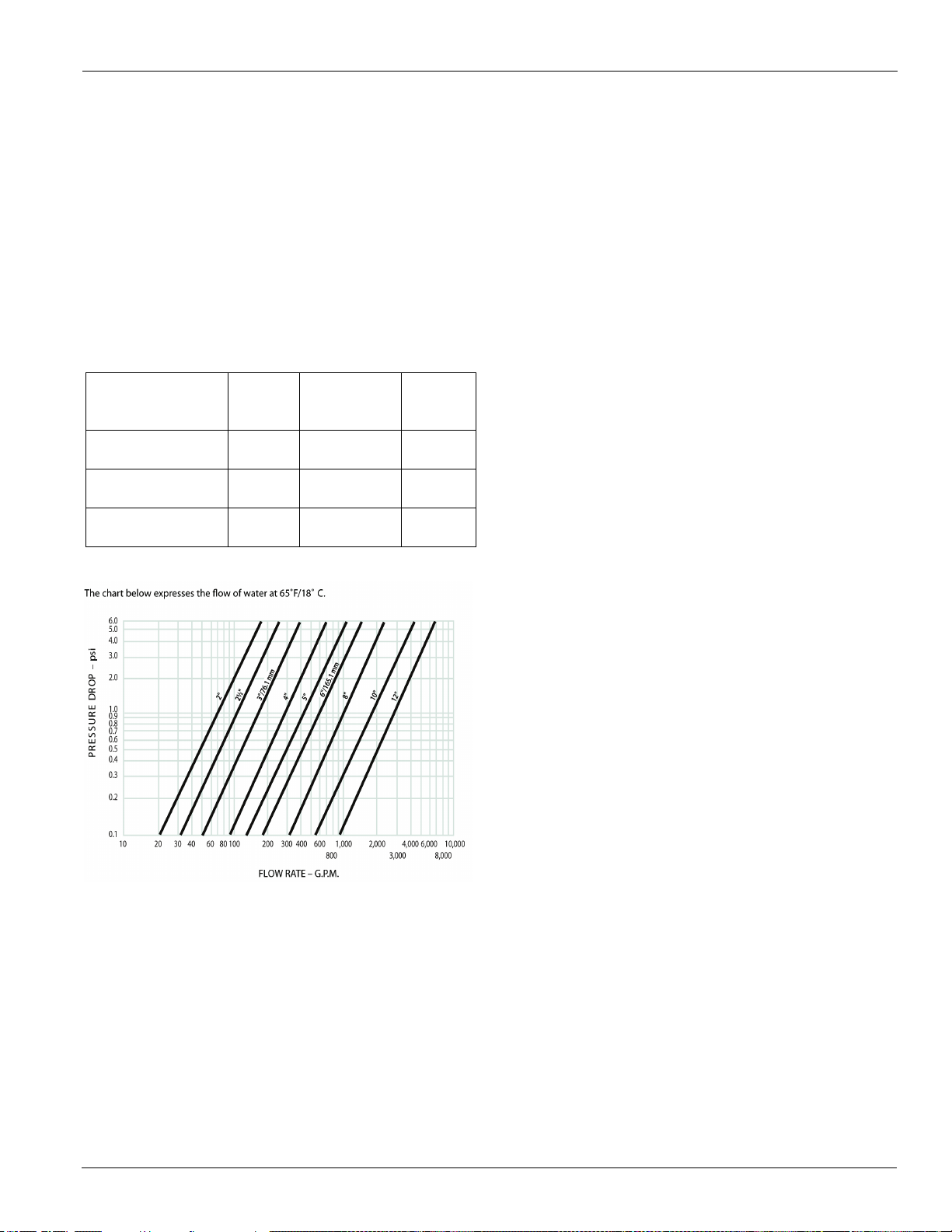
Optional Inlet Strainer
An inlet water strainer kit is available as a shipped-loose
option, sized per Tab le 2 and with the pressure drop shown in
Figure 12. The kit is field installed and consists of:
• Y-type 40% open area strainer with 304 stainless steel
perforated basket, Victaulic pipe connections and
strainer cap
• Extension pipe with two Schrader fittings that can be
used for a pressure gauge and thermal dispersion flow
switch. The pipe provides sufficient clearance from the
evaporator for strainer basket removal.
• ½-inch blowdown valve
• Two Victaulic clamps
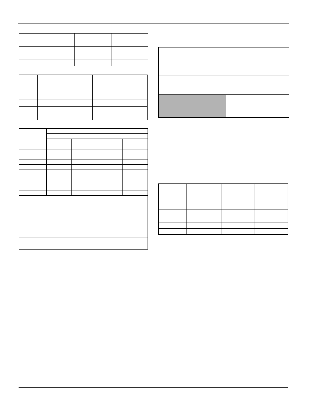
Table 2: Strainer Sizing Data
AWS Model
175ADS-250ADS
210ADH-250ADH
280ADS-350ADS
280ADH-405ADH
375ADS-530ADS
445ADH-530ADH
Figure 12: Strainer Pressure Drop
Strainer
Size (in.)
630.572
8 36.0 125
10 43.0 205
Strainer Plus
Pipe Length
(in.)
Strainer
Weight
(lbs)
McQuay thermal dispersion flow switch and a water pressure
gauge. The ball valve can be installed in the strainer basket
cover as a blow-down valve.
System Water Volume
All chilled water systems need adequate time to recognize a
load change, respond to that load change and stabilize, without
undesirable short cycling of the compressors or loss of control.
In air conditioning systems, the potential for short cycling
usually exists when the building load falls below the minimum
chiller plant capacity or on close-coupled systems with very
small water volumes.
Some of the things the designer should consider when looking
at water volume are the minimum cooling load, the minimum
chiller plant capacity during the low load period and the
desired cycle time for the compressors.
Assuming that there are no sudden load changes and that the
chiller plant has reasonable turndown, a rule of thumb of
"gallons of water volume equal to two to three times the
chilled water gpm flow rate" is often used.
A properly designed storage tank should be added if the
system components do not provide sufficient water volume.
Variable Speed Pumping
Variable water flow involves reducing the water flow through
the evaporator as the load decreases. Daikin McQuay chillers
are designed for this duty, provided that the rate of change in
water flow is slow, and the minimum and maximum flow rates
for the evaporator are not exceeded.
Installing Optional Inlet Strainer
The extension pipe is located adjacent to the evaporator with
the strainer then mounted to it. The strainer must be mounted
per manufacturer's instruction with the arrows in the direction
of flow; inlet and outlet are noted along with the arrows.
Use one Victaulic clamp to mount the extension pipe to the
evaporator and the second to mount the strainer to the pipe.
The clamps to mount the field piping to the strainer are field
supplied. The piping and strainer must be supported to prevent
any stress on the evaporator nozzle.
The extension pipe has two Schrader fittings that can be used
as desired, frequently for mounting the optional Daikin
The recommended maximum change in water flow is 10
percent of the change per minute. For example, if the
maximum (design) flow is 200 gpm and the flow is reduced to
a minimum of 140 gpm, the change in flow is 60 gpm, so the
maximum change per minute would be 10% of 60, or 6 gpm
per minute. It would take ten minutes to change the flow
through the entire range.
The water flow through the evaporator must remain between
the minimum and maximum values listed on page 108. If flow
drops below the minimum allowable, large reductions in heat
transfer can occur. If the flow exceeds the maximum rate,
excessive pressure drop and tube erosion can occur.
Evaporator Freeze Protection
Pathfinder chillers are equipped with thermostatically
controlled evaporator heaters that help protect against freezeup down to -20°F (-28°C). The immersion heater itself may
not be able to properly protect the evaporator from freezing
without circulation of water, and it is important that the chilled
water pumps are wired to, and controlled by, the chiller’s
controller. Additionally, use at least one of the following
procedures during periods of sub-freezing temperatures:
1 Add a concentration of a glycol anti-freeze with a freeze
point 10°F below the lowest expected temperature. This
IM 1167 11
Page 12
Installation and Startup
on s wit ch
1" (25mm) NPT flow
switch connection
Tee
dia. min. before switch
1 1/4" (32mm) pipe
dia. min. after switch
on switch
1" (25mm) NPT flow
switch connection
1 1/4" (32mm) pipe
dia. min. before switch
1 1/4" (32mm) pipe
dia. min. after switch
Tee
will result in decreased capacity and increased pressure
drop. Note: Do not use automotive grade antifreezes as
they contain inhibitors harmful to chilled water systems.
Use only glycols specifically designated for use in
building cooling systems.
2 Drain the water from outdoor equipment and piping and
blow the chiller tubes dry from the chiller. Do not
energize the chiller heater when water is drained from
the vessel.
Note: The heaters come from the factory connected to the
control power circuit. The control power can be rewired
in the field to a separate 115V supply (do not wire directly
to the heater). See the field wiring diagram on page 65. If
this is done, it should power the entire control circuit.
Mark the disconnect switch clearly to avoid accidental
deactivation of the heater during freezing temperatures.
Exposed chilled water piping also requires protection. If
the evaporator is drained for winter freeze protection, the
heaters must be de-energized to prevent heater
burnout..
Table 3: Freeze Protection
% Volume Glycol Concentration Required
Temp.
F (C)
20 (6.7) 16 18 11 12
10 (-12.2) 25 29 17 20
0 (-17.8) 33 36 22 24
-10 (-23.3) 39 42 26 28
-20 (-28.9) 44 46 30 30
-30 (-34.4) 48 50 30 33
-40 (-40.0) 52 54 30 35
-50 (-45.6) 56 57 30 35
-60 (-51.1) 60 60 30 35
Note: “Freeze protection” maintains the solution in a pumpable, usable
Note: These figures are examples only and cannot be appropriate to every
Note: Glycol of less than 25% concentration is not recommended because
Table 4: Paddle Type Flow Switch Flow Rates
Note:
Note:
Note:
Note:
Note:
For Freeze Protection For Burst Protection
Ethylene
Glycol
liquid state. “Burst protection” prevents pipes from rupturing, but
solution may be in a gel state and not pumpable. In most
applications, “burst” protection is sufficient; concentrations over 30%
Ethylene Glycol or 35% Propylene Glycol will result in efficiency and
capacity losses with negligible protection increases
situation. Generally, for an extended margin of protection, select a
temperature at least 15°F lower than the expected lowest ambient
temperature. Inhibitor levels should be adjusted for solutions less
than 25% glycol.
of the potential for bacterial growth and loss of efficiency.
Pipe Size
(NOTE) - (2) (2) (3) (4) (4) (4) (5)
1
A segmented 3-inch paddle (1, 2, and 3 inches) is furnished mounted, plus a 6-inch paddle loose.
2
Flow rates for a 2-inch paddle trimmed to fit the pipe.
3
Flow rates for a 3-inch paddle trimmed to fit the pipe.
4
Flow rates for a 3-inch paddle.
5
Flow rates for a 6-inch paddle.
Propylene
Glycol
inch 1 1/4 1 1/2 2 2 1/2 3 4 5 6 8
mm 32 38 51 63 76 102 127 153 204
Ethylene
Glycol
Propylene
Glycol
Flow Switch
A flow switch must be included in the chilled water system to
prove that there is adequate water flow before the unit can
start. It also serves to shut down the unit in the event that water
flow is interrupted in order to guard against evaporator freezeup.
A factory-mounted, solid state, thermal dispersion flow switch
is available as an option. A field-installed version is also
available as a kit (Accessory part number 332688401).
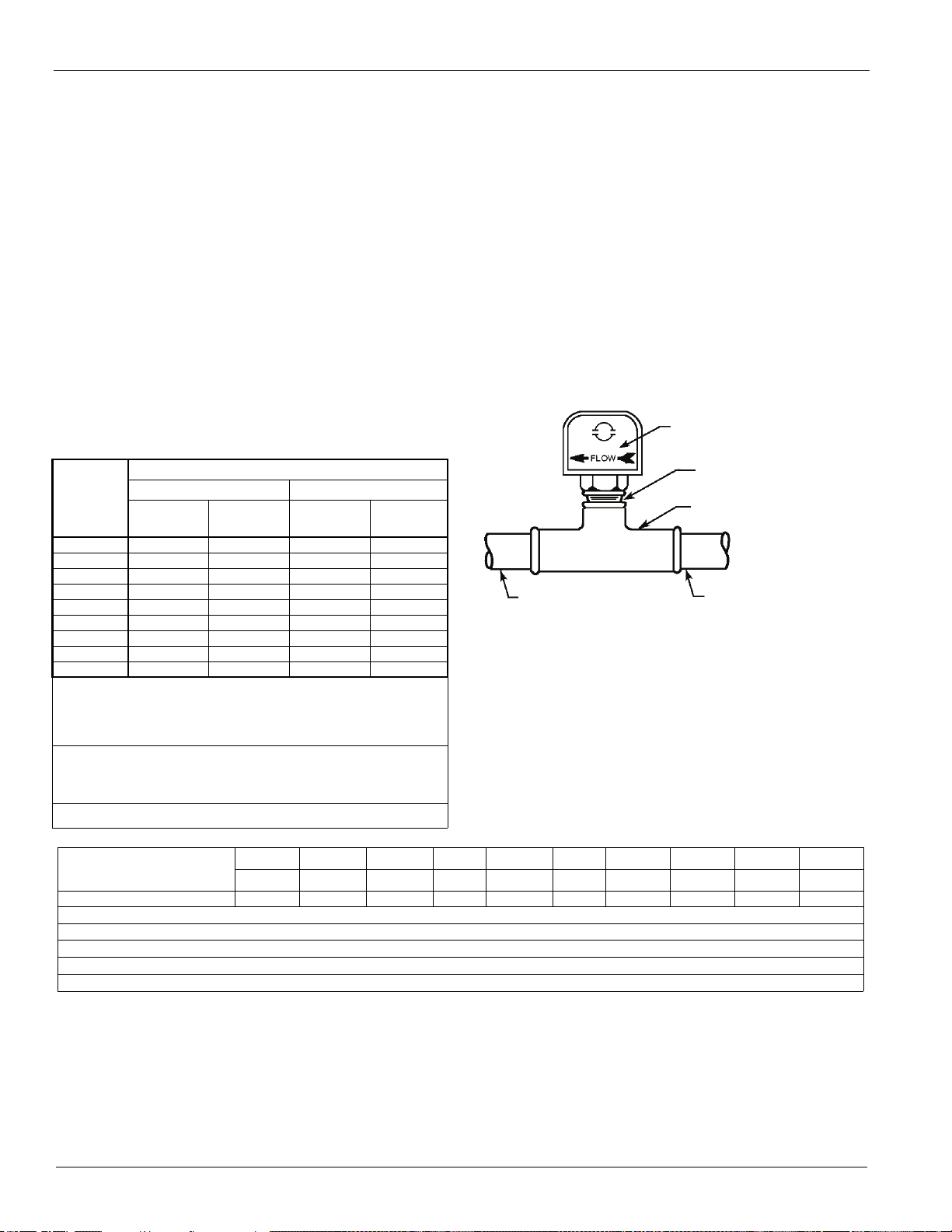
A paddle-type flow switch for field mounting and wiring is
also available as a kit (Accessory part number 017503300). It
is adaptable to pipe sizes from 1" (25mm) to 8" (203mm).
Certain minimum flow rates are required to close the switch
and are listed in Table 4. Installation should be as shown in
Figure 13.
Fl ow di r e ction marke d
Flow direction marked
1 1/4" (32mm) pipe
Electrical connections in the unit control center should be
made at terminals 60 and 67 from switch terminals Y and R.
The normally open contacts of the flow switch should be wired
between these two terminals. Flow switch contact quality must
be suitable for 24 VAC, low current (16ma). Flow switch wire
must be in separate conduit from any high voltage conductors
(115 VAC and higher) and have an insulation rating of 600
volts.
12 IM 1167
Page 13
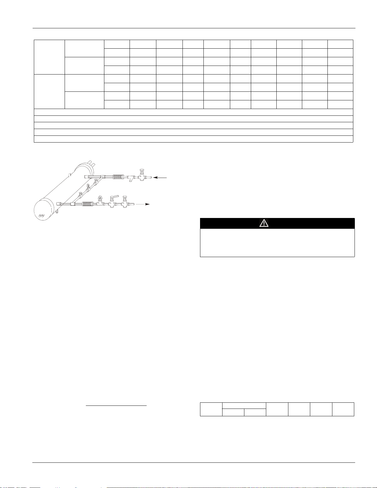
Table 4: Paddle Type Flow Switch Flow Rates
Drain
Gate
Water
Strainer
Eliminator
Pressure
Gauge
In
Out
Protect All Field Piping
Against Freezing
Flow
Eliminator
Flow
Switch
Balancing
Gate
Flow
Liquid
Suction
TDelta
factorflowtons
GPM
24
Min.
Flow
Adjst.
No Flow
Flow
Max.
Adjst.
No Flow
Note: 1A segmented 3-inch paddle (1, 2, and 3 inches) is furnished mounted, plus a 6-inch paddle loose.
2
Flow rates for a 2-inch paddle trimmed to fit the pipe.
Note:
3
Flow rates for a 3-inch paddle trimmed to fit the pipe.
Note:
4
Flow rates for a 3-inch paddle.
Note:
5
Flow rates for a 6-inch paddle.
Note:
gpm
Lpm
gpm
Lpm
gpm
Lpm
gpm
Lpm
5.8 7.5 13.7 18.0 27.5 65.0 125.0 190.0 205.0
1.3 1.7 3.1 4.1 6.2 14.8 28.4 43.2 46.6
3.7 5.0 9.5 12.5 19.0 50.0 101.0 158.0 170.0
0.8 1.1 2.2 2.8 4.3 11.4 22.9 35.9 38.6
13.3 19.2 29.0 34.5 53.0 128.0 245.0 375.0 415.0
3.0 4.4 6.6 7.8 12.0 29.1 55.6 85.2 94.3
12.5 18.0 27.0 32.0 50.0 122.0 235.0 360.0 400.0
2.8 4.1 6.1 7.3 11.4 27.7 53.4 81.8 90.8
Installation and Startup
Figure 13: Typical Field Water Piping
4 Power - To determine glycol system kW, multiply the
water system kW by the factor designated "Power".
Test coolant with a clean, accurate glycol solution hydrometer
Vent
Valved
Vibration
Valve
(similar to that found in service stations) to determine the
freezing point. Obtain percent glycol from the freezing point
table below. On glycol applications, the supplier normally
recommends that a minimum of 25% solution by weight be
used for protection against corrosion or that additional
Vibration
Valve
Valve
inhibitors should be employed.
CAUTION
Note:
Connections for vent and drain fittings are located on the top
and bottom of the evaporator.
Note: Piping must be supported to avoid putting strain on the
evaporator nozzles.
Do not use automotive grade antifreeze. Industrial grade glycols must
be used. Automotive antifreeze contains inhibitors that will cause
plating on the copper tubes within the chiller evaporator. The type and
handling of glycol used must be consistent with local codes.
Refrigerant Charge
All packaged units are designed for use with R-134a and are
shipped with a full operating charge. The operating charge for
each unit is shown in the Physical Data Tables beginning on
page 15.
Glycol Solutions
When using glycol anti-freeze solutions, the chiller's capacity,
glycol solution flow rate, and pressure drop through the
evaporator can be calculated using the following:
Note: The procedure below does not specify the type of
glycol. Use the derate factors found in Table 5 or Table 6
forcorrections when using glycol.
1 Capacity - Cooling capacity is reduced from that with
plain water. To find the reduced value, multiply the
chiller’s water system tonnage by the capacity correction
factor to find the chiller’s capacity when using glycol.
2 Flow - To determine flow (or Delta-T) knowing Delta-T
(or flow) and capacity:
3 Pressure drop - To determine pressure drop through the
evaporator when using glycol, enter the water pressure
drop curve at the water flow rate. Multiply the water
pressure drop found there by the "PD" factor to obtain
corrected glycol pressure drop.
IM 1167 13
Performance Adjustment Factors
AWS chiller units are designed to operate with leaving chilled
fluid temperatures of 20.0°F to 60.0°F (-6.7°C to 15.6°C).
Consult the local Daikin McQuay sales office for performance
outside these temperatures. Leaving chilled fluid temperatures
below 40°F (4.4°C) result in evaporating temperatures at or
below the freezing point of water and a glycol solution is
required. MicroTech III control inhibits compressor unloading
at leaving fluid temperatures below 30°F (-1°C).
Low fluid temperatures or high equipment room humidity may
require optional double evaporator insulation. The system
designer should determine its necessity. The use of glycol will
reduce the performance of the unit depending on its concentration. Take this into consideration during initial system design.
On glycol applications, the supplier typically recommends that
a minimum of 25% solution by weight be used for protection
against corrosion, or additional inhibitors will be required.
Table 5: Ethylene Glycol Correction Factors
% E.G
Freeze Point
o
F
o
Capacity Power Flow PD
C
Page 14
Installation and Startup
Table 5: Ethylene Glycol Correction Factors
10 26 -3.3 0.996 0.998 1.036 1.097
20 18 -7.8 0.988 0.994 1.061 1.219
30 7 -13.9 0.979 0.991 1.092 1.352
40 -7 -21.7 0.969 0.986 1.132 1.532
50 -28 -33.3 0.958 0.981 1.182 1.748
Table 6: Propylene Glycol Correction Factors
Freeze Point
% P.G
10 26 -3.3 0.991 0.996 1.016 1.092
20 19 -7.2 0.981 0.991 1.032 1.195
30 9 -12.8 0.966 0.985 1.056 1.345
40 -5 -20.6 0.947 0.977 1.092 1.544
50 -27 -32.8 0.932 0.969 1.14 1.906
o
F
o
Capacity Power Flow PD
C
Table 7: Ambient Freeze Protection
Percent Volume Glycol Concentration Required
For Freeze Protection For Burst Protection
Temperature
F (C)
20 (6.7) 16 18 11 12
10 (-12.2) 25 29 17 20
0 (-17.8) 33 36 22 24
-10 (-23.3) 39 42 26 28
-20 (-28.9) 44 46 30 30
-30 (-34.4) 48 50 30 33
-40 (-40.0) 52 54 30 35
-50 (-45.6) 56 57 30 35
-60 (-51.1) 60 60 30 35
Note: “Freeze protection” maintains the solution ina pumpable, usable
liquid state. “Burst protection” prevents pipes from rupturing, but the
solution may be in a gel state and not pumpable. In most
applications, “burst” protection is sufficient; concentrations over
30% Ethylene Glycol or 35% Propylene Glycol will result in
efficiency and capacity losses with negligible protection increases.
Note: These figures are examples only and may not be appropriate to
every situation. Generally, for an extended margin of protection,
select a temperature at least 15°F (-12°C) lower than the expected
lowest ambient temperature. Adjust inhibitor levels for solutions
less than 25% glycol
Note: Glycol of less than 25% concentration is not recommended because
of the potential for bacterial growth and subsequent loss of heat
transfer efficiency. Additional inhibitors may be required.
Ethylene
Glycol
Propylene
Glycol
Ethylene
Glycol
Propylene
Glycol
Electrical Connections
All wiring must be done in accordance with applicable local
and national codes. Pathfinder units can be ordered with either
standard multi-point power or optional single point power
connections and with various disconnect and circuit breaker
options. Wiring within the unit is sized in accordance with the
U.S.A. National Electrical Code. Field-supplied disconnect
switches are required if not factory-supplied with the unit.
Table 8: Electric Power Connection Option
Multi-Point
Power Connection
Disconnect switch per circuit, no
compressor isolation circuit breakers
High short circuit current rated panel
with disconnect switch and no
Note: Disconnect switches are molded case construction with lockable
Note: The individual compressor isolation circuit breakers for each circuit
Note: The high short circuit rated panel means that a short circuit current
Note: The factory-mounted control power transformer is protected by fuses.
Standard:
Optional:
isolation circuit breakers
through-the-door handles. They can be used to remove the unit/
circuit from the power system.
isolate the compressor and do not have through-the-door handles.
They are operable only after the panel doors are opened.
up to the ratings shown in Table 9, Interrupt Ratings (kAmps)will be
contained in the panel. There is a short period of time when the
circuit breaker will short circuit before opening a circuit that can
damage downstream components. In other words, the enclosure is
stronger than a standard enclosure. It has a high interrupt rated
disconnect switch.
Condenser fans are protected and isolated by circuit breakers.
One disconnect switch replacing
panel with disconnect switch and
Single-Point
Power Connection
one power block, compressor
the power block, compressor
High short circuit current rated
compressor isolation circuit
Optional:
isolation circuit breakers
Optional:
isolation circuit breakers
Optional:
breakers
Table 9: Interrupt Ratings (kAmps)
STANDARD
VOLTAGE
208-230 10kA 100kA 208-230
380 10kA 65kA 380
460 10kA 65kA 460
575 5kA 25kA 575
SHORT
CIRCUIT
PANEL
RATING
HIGH SHORT
CIRCUIT
RATED
PANEL
VOLTAGE
Disconnecting means are addressed by Article 440 of the
U.S.A. National Electrical Code (NEC), which requires
“disconnecting means capable of disconnecting air
conditioning and refrigerating equipment including motorcompressors, and controllers from the circuit feeder.” Select
and locate the disconnect switch per the NEC guidelines.
Maximum recommended fuse sizes are given in the electrical
data tables of this catalog for help in sizing the disconnect.
Terminals are provided in a unit control panel for optional field
hookup of the control circuit to a separate fused 115-volt
power supply in lieu of the standard factory installed control
transformer.
RapidRestore Option
This option does not require field installation. Exception: Field
supplied inputs are required in the case of a backup unit being
started after the power interruption rather than restarting the
primary unit.. A field supplied control (normally a BAS) must
turn off the Backup Chiller connection on the primary chiller
and turn on the connection on the backup chiller at the time of
switching. See the unit Field Wiring Diagram for the Backup
Unit connection point (terminals #61 and #62).
14 IM 1167
Page 15
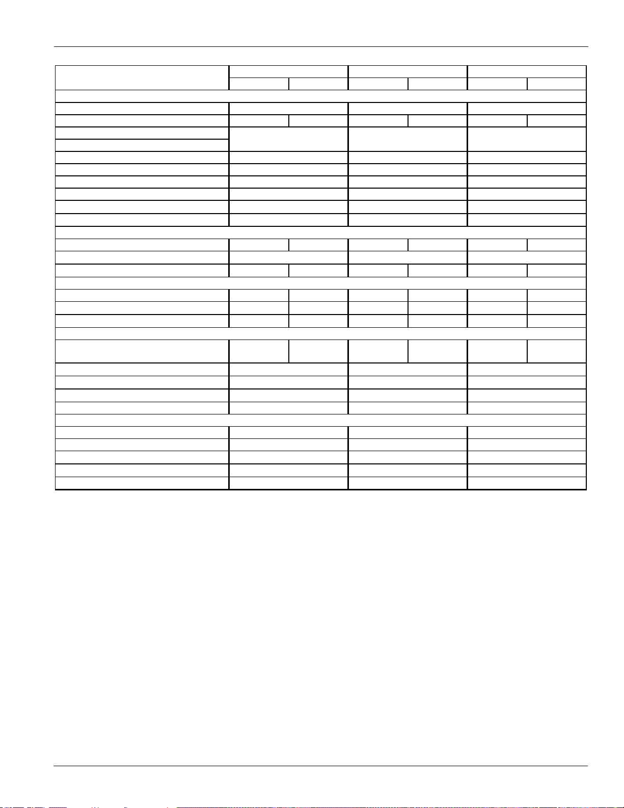
Physical Data (non-VFD)
CIRCUIT 1 CIRCUIT 2 CIRCUIT 1 CIRCUIT 2 CIRCUIT 1 CIRCUIT 2
BASIC DATA
Unit Cap. @ AHRI tons (kW)
Unit O per ating Charge lbs (kg) 145 (66) 145 (66) 165 (75) 165 (75) 165 (75) 165 (75)
Unit Dimensions
L x W x H, in. (mm)
Unit Oper ating W eig ht, lbs. ( k g)
Unit S hipping W eight , lbs (kg)
Weight - Add for Copper Fins, lbs (kg)
g
Weight - Add for PFCC opt ion, lbs (kg)
COMPRESSORS, SCREW, SEMI-HERMETIC
Nominal Capacity, tons (kW) 95 (334) 95 (334) 95 (334) 115 (404) 115 (404) 115 (404)
Minimum Capacity (% of F ull Load )
Oil char ge per c ir cuit , gallons (liters) 4.5 (17) 4.5 (17) 4.5 (17) 5.5 (21) 5.5 (21) 5.5 (21)
CONDENSERS, HIGH EF FICIENCY F IN AND TUBE TYPE
Pumpdown Capacity, lbs (kg) 208 (94) 208 (94) 250 (113) 250 (113) 250 (113) 250 (113)
Coil Inlet Face Area, sq. ft. ( sq. m.) 123.1 (11.4) 123.1 (11.4) 147.7 (13. 7) 147.7 (13.7) 147.7 (13. 7) 147.7 (13.7)
Rows Deep/Fins Per Inch 3 / 16 3 / 16 3 / 16 3 / 16 3 / 16 3 / 16
CONDENSER FANS, DIRECT DRIVE PROPELLER TYPE
Fan Motor, hp (kW)
Fan & Motor RPM
Fan T ip S peed, f pm (m/s)
A irflow, cfm (l/s)
EVAPORATOR, DIRECT EXPANSION SHELL AND TUBE
Shell Dia.-Tube Length, in.(mm)
Water Volume, gallons (liters)
Victaulic inlet/outlet conn. in. (mm)
M ax. W ater Pressure, psi (kPa)
Max. Refrigerant Press., psi (kPa)
180.1 (633) 201.3 (708) 216.3 (760)
Data
AWS190BDS AWS210BDS AWS225BDS
245 x 88 x 100 245 x 88 x 100
(6220 x 2225 x 2548 ) (6220 x 2225 x 2548 ) (6220 x 2225 x 25 48)
13072 (5930) 13788 (6255)
245 x 88 x 100
12529 (5684) 13245 (6008)
1786 (810)
56
160 (73)
15 15
676 (307) 788 (357)
110850 (52315)
5
1.4 (1.05)
6984 (35)
850 850 850
666
1.4 (1.05)
477 (216) 477 (216) 477 (216)
1786 (810) 1786 (810)
66 (251)
15
6984 (35)
14335 (6503)
13792 (6256)
16 x 108 (40 6 x 2750) 16 x 108 (40 6 x 2750)
6984 (35)
66 (251)
1.4 (1.05)
788 (357)
160 (73)
6 (168) 6 (168) 6 (168)
325 (2241) 325 (2241) 325 (2241)
152 (1048) 152 (1048)
133020 (62778) 133020 (62778)
152 (1048)
16 x 406 (40 6 x 2750)
68 (258)
160 (73)
Note: A 20 mesh strainer must be placed in the supply water line just prior to the inlet of the evaporator.
Care must be exercised when welding pipe or flanges to the evaporator to prevent any slag from entering the vessel.
This information applies only to Rev 0B models of AWS-B. For Rev 00 models, consult CAT 600-6; Rev 0A, CAT 600-7.
Table 10: Physical Data (60 Hz, Standard Efficiency, non-VFD models)
Weight - Add for Louvered Panels, lbs (kg)
Weight-Add for S oun d E nc l osures, lbs (k
Physical Data (non-VFD)
Number of Fans per Circuit
Fan Diameter: 31.5 in. ( 800 mm)
IM 1167 15
Page 16
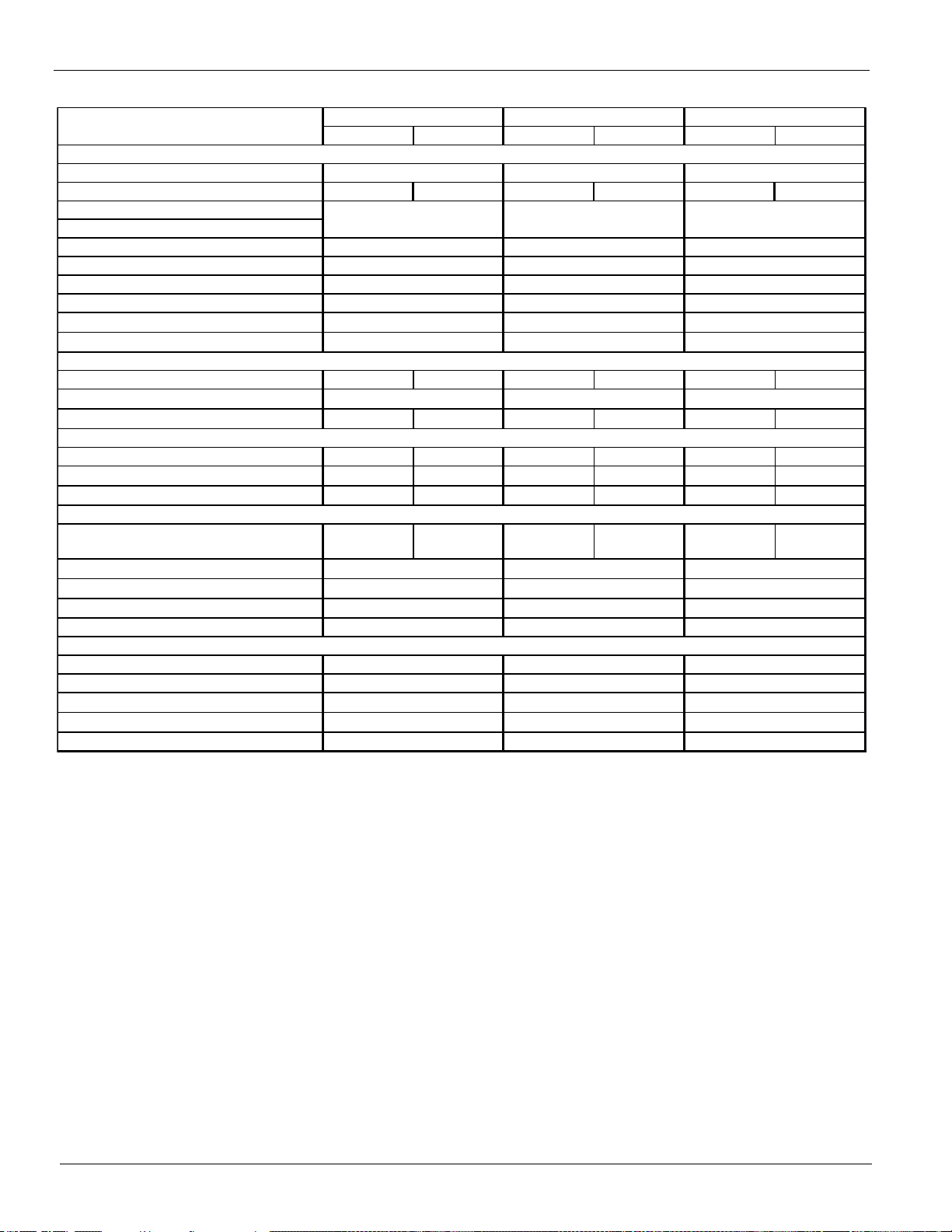
Physical Data (non-VFD)
CIRC U IT 1 CIRCUIT 2 C IRC U IT 1 CIRCUIT 2 CIRCUIT 1 CIR C U IT 2
BASIC DATA
Unit Cap. @ AHRI tons (kW)
Unit O per ating Charge lbs (kg) 185 (84) 185 (84) 185 (84) 185 (84) 210 (95) 210 (95)
Unit Dimensions
L x W x H, in. (mm)
Unit O per ating W eight, lbs. (k g)
Unit Shipping Weight , lbs (kg)
Weight - Add for Copper Fins, lbs (kg)
Weight - Add for Louvered Panels, lbs (kg)
g
Weight - Add for P F CC option, lbs (kg)
COMPRESSORS, SC REW, SEMI -HE RMETI C
Nominal Capacity, tons (kW ) 115 (404) 135 (475) 135 (475) 135 (475) 135 (475) 155 (545)
Minimum Capacity (% of F ull Load)
Oil char ge per c ir c uit , gallons (liter s) 5.5 (21) 5.5 ( 21) 5.5 (21) 5.5 (21) 5.5 (21) 6 (23)
CONDENSERS, HIGH EF FICIENCY FIN AND TUBE TYPE
Pumpdown Capacity, lbs (kg) 291 (132) 291 (132) 291 (132) 291 (132) 333 (151) 333 (151)
Coil Inlet Face Area, sq. f t. ( sq. m.) 172.3 (16. 0) 172.3 (16.0) 172.3 (16. 0) 172.3 ( 16.0) 196.9 ( 18. 3) 196.9 (18. 3)
Rows Deep/Fins Per I nc h 3 / 16 3 / 16 3 / 16 3 / 16 3 / 16 3 / 16
CONDENSER FANS, DIRECT DRIVE PROPELLER TYPE
Fan Motor, hp ( kW)
Fan & Motor RP M
Fan T ip S peed, f pm (m/s)
Airflow, cfm (l/s )
EVAPORATOR, DIRECT EXPANSION SHELL AND TUBE
Shell Dia.- Tube Lengt h, in. ( mm)
Water Volume, gallons (liters)
Vict aulic inlet/ outlet c onn. in. ( mm)
M ax. W ater Pressure, psi (kPa)
Max. Refrigerant P ress., psi (kPa)
AWS290BDS
235.8 (829)
AWS260BDS
280 x 88 x 100
(7121 x 2225 x 2548)
15188 (6890)
Data
2084 (945)
AWS250BDS
14645 (6643)
2084 (945)
6984 (35)
152 (1048)
850
6984 (35)
900 (408)
477 (216)
177360 (83704)
15
325 (2241)
1.4 ( 1.05)
850
1.4 ( 1.05)
77 88
6984 (35)
16624 (7541)
2372 (1076)
1012 (459)
15
77
160 (73) 160 (73)
850
64 (243)
6 (168)
20 x 108 / (508 x 2750)
282.9 (995)
316 x 88 x 100
(8022 x 2225 x 2548)
17491 (7934)
477 (216)
15
325 (2241)
155190 (73241)
325 (2241)
107 (403)
8 (219)
152 (1048)
16 x 108 / (406 x 2750)
64 (243)
6 (168)
152 (1048)
250.5 (881)
280 x 88 x 100
(7121 x 2225 x 2548)
15188 (6890)
155190 (73241)
16 x 108 / (406 x 2750)
1.4 ( 1.05)
14645 (6643)
900 (408)
477 (216)
160 (73)
Note: A 20 mesh strainer must be placed in the supply water line just prior to the inlet of the evaporator.
Care must be exercised when welding pipe or flanges to the evaporator to prevent any slag from entering the vessel.
This information applies only to Rev 0B models of AWS-B. For Rev 00 models, consult CAT 600-6; Rev 0A, CAT 600-7.
Table 11: Physical Data (60 Hz, Standard Efficiency, non-VFD models)
Weight - Add for S ound Enc losures, lbs (k
Number of Fans per Circ uit
Fan Diameter : 31. 5 in. (800 mm)
16 IM 1167
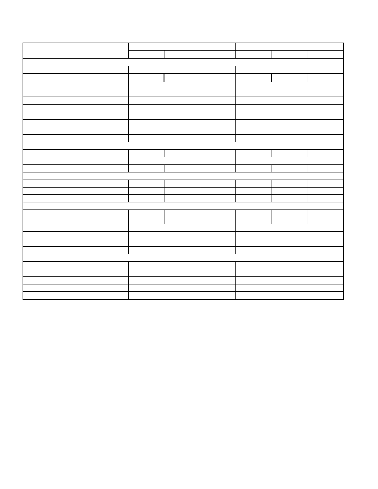
Page 17
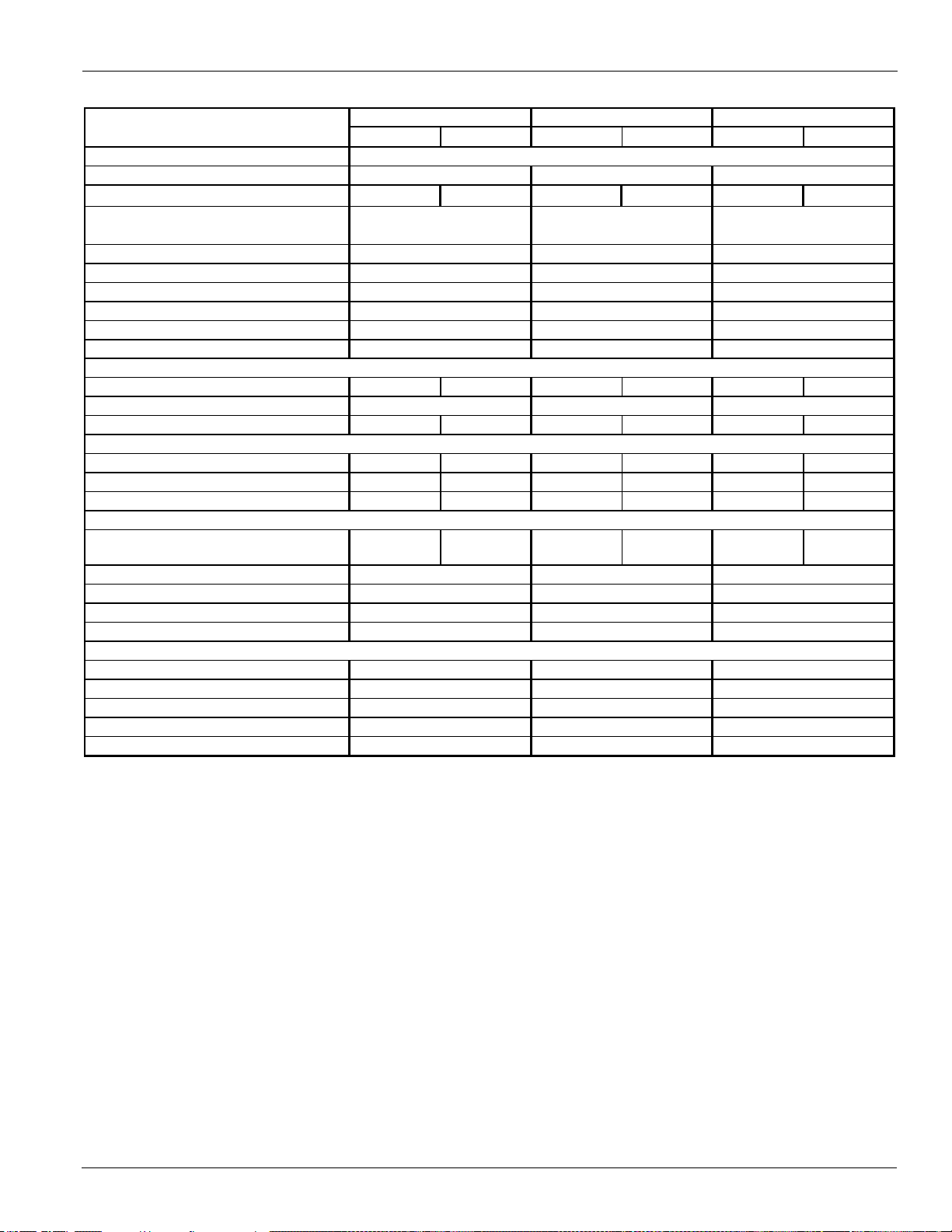
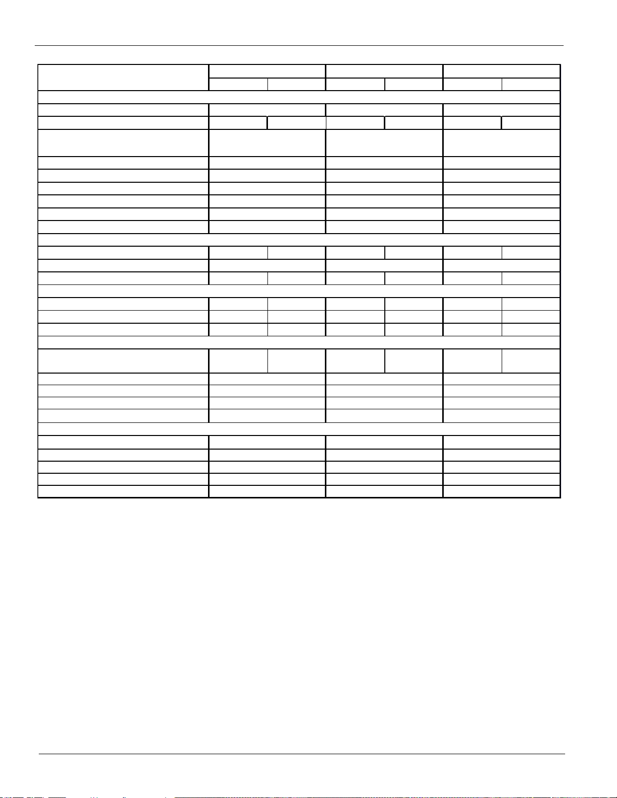
Table 12: Physical Data (60 Hz, Standard Efficiency, non-VFD models)
CIRCUIT 1 CIRCUIT 2 CIRCUIT 1 CIRCUIT 2 CIRCUIT 1 CIRCUIT 2
BASIC DATA
Unit Cap. @ AHRI tons (kW)
Unit O per at ing Char ge lbs (kg) 215 (98) 215 (98) 265 (120) 265 (120) 265 (120) 265 (120)
Unit Dimensions
L x W x H, in. (mm)
Unit O perating W eight, lbs. (kg)
Unit S hipping Weight , lbs (kg)
Weight -Add for Copper F ins, lbs (kg)
g
Weight - Add for PFCC option, lbs (kg)
COMPRESSORS, SCREW, SEMI-HERMETIC
Nominal Capacity, tons (kW ) 155 ( 545) 155 (545) 155 (545) 185 (650) 185 (650) 185 (650)
Minimum Capacity (% of F ull Load)
Oil char ge per circ uit , gallons (liters) 6 ( 23) 6 (23) 6 (23) 6 (23) 6 (23) 6 (23)
CONDENSERS, HIGH EFFICIENCY FIN AND TUBE TYPE
Pumpdown Capacity, lbs (kg) 333 (151) 333 (151) 416 (189) 416 (189) 416 (189) 416 (189)
Coil Inlet F ac e Area, sq. ft . ( sq. m.) 196.9 (18. 3) 196.9 (18.3) 246.1 (22. 8) 246.1 (22. 8) 246.1 (22. 8) 246.1 (22. 8)
Rows Deep/Fins Per Inch 3 / 16 3 / 16 3 / 16 3 / 16 3 / 16 3 / 16
CONDENSER FANS, DIRECT DRIVE PROPELLER TYPE
Fan Motor, hp (k W)
Fan & Motor RPM
Fan Tip Speed, f pm (m/s)
A irflow, cfm (l/s)
EVAPORATOR, DIRECT EXPANSION SHELL AND TUBE
Shell Dia.-Tube Length, in. ( mm)
Wat er Volume, gallons (liters)
V ic t aulic inlet / out let c onn. in. (mm)
M ax. W ater Pressure, psi (kPa)
Max. Refrigerant Press., psi (kPa)
18161 (8238) 19803 (8983)
(8026 x 2225 x 2548) (9823 x 2225 x 2548)
316 x 88 x 100 387 x 88 x 100
(9823 x 2225 x 2548)
387 x 88 x 100
300.4 (1056) 340.6 (1197) 361.4 (1271)
Data
AWS310BDS AWS350BDS AWS375BDS
17294 (7845) 18936 (8590) 18936 (8590)
2372 (1076) 2968 (1346) 2968 (1346)
1012 (459) 1236 (561) 1236 (561)
477 (216) 477 (216) 477 (216)
15 15 15
160 (73)
8810
20 x 108 / ( 508 x 2750)
1.4 ( 1. 05 ) 1. 4 (1 . 05)
10
20 x 108 / (508 x 2750)
8 (219) 8 (219) 8 (219)
152 (1048) 152 (1048)
325 (2241) 325 (2241) 325 (2241)
20 x 108 / ( 508 x 2750)
107 (403)
10 10
19803 (8983)
160 (73) 160 (73)
102 (386) 102 (386)
6984 (35) 6984 (35) 6984 (35)
177360 (83704) 221700 (104630) 221700 (104630)
152 (1048)
1.4 (1.05)
850 850 850
Note: A 20 mesh strainer must be placed in the supply water line just prior to the inlet of the evaporator.
Care must be exercised when welding pipe or flanges to the evaporator to prevent any slag from entering the vessel.
This information applies only to Rev 0B models of AWS-B. For Rev 00 models, consult CAT 600-6; Rev 0A, CAT 600-7.
Weight - Add for Louvered Panels, lbs (kg)
Weight - Add for Sound Enc losures, lbs (k
Physical Data (non-VFD)
Number of F ans per Cir cu it
Fan Diameter: 31.5 in. ( 800 mm)
IM 1167 17
Page 18
Physical Data (non-VFD)
CIRC U IT 1 CIRCU IT 2 C IR C U IT 3 CIRCUIT 1 CIRCU IT 2 CIRCUIT 3
BASIC DATA
Unit Cap. @ AHRI tons (kW )
Unit O per at ing Char ge lbs (kg) 185 (84) 185 (84) 220 (100) 185 (84) 185 (84) 220 (100)
Unit Dimensions
L x W x H, in. (mm)
Unit O per at ing Weight, lbs. (kg)
Unit Shipping Weight, lbs (kg)
Weight - Add for Copper F ins, lbs (kg)
Weight - Add for Louvered P anels, lbs (kg)
g
Weight - Add for PF CC option, lbs (kg)
COMPRESSOR S, SC RE W, SE MI -H ER METI C
Nominal Capacity , t ons (kW ) 135 (475) 135 (475) 135 (475) 135 (475) 135 (475) 155 (545)
Minimum Capacity (% of F ull Load)
Oil char ge per c ir cuit , gallons (liters) 5.5 (21) 5.5 (21) 5.5 (21) 5.5 (21) 5.5 (21) 6 ( 23)
CONDENSERS, HIGH EFFICIENCY FIN AND TUBE TYPE
Pumpdown Capacity, lbs (kg) 291 (132) 291 (132) 333 (151) 291 (132) 291 (132) 333 (151)
Coil Inlet Face Area, sq. ft. (sq. m.) 172.3 (16. 0) 172.3 ( 16. 0) 196.9 (18.3) 172.3 ( 16. 0) 172.3 (16.0) 196.9 ( 18. 3)
Rows Deep/Fins Per Inc h 3 / 16 3 / 16 3 / 16 3 / 16 3 / 16 3 / 16
CONDENSER FANS, DIRECT DRIVE PROPELLER TYPE
Fan Motor, hp ( k W)
Fan & Motor RP M
Fan T ip S peed, fpm (m/s)
Airflow, cfm (l/s)
EVAPORATOR, DIRECT EXPANSION SHELL AND TUBE
Shell Dia.-Tube Lengt h, in. ( mm)
Water Volume, gallons (liters)
Vict aulic inlet / outlet conn. in. ( mm)
M ax. W at er Pressure, psi (kPa)
Max. Refrigerant Press., psi (kPa)
AWS425BTS
Data
418.7 (1472)
438 x 88 x 100
AWS400BTS
398.3 (1400)
(11123 x 2225 x 2548)
24931 (11309)
23532 (10674)
3256 (1477)
6984 (35)
120 (55) 120 (55)
778
1.4 ( 1. 05)
8
850
1.4 (1.05)
850
266040 (125556) 243870 (115094)
26 x 130 / (660 x 3300)
225 (850)
26 x 130 / (660 x 3300)
225 (850)
10 (273)
152 (1048)
10 (273)
152 (1048)
325 (2241)325 (2241)
24260 (11005)
22861 (10370)
3256 (1477)
77
1348 (611)
776 (352)
8
6984 (35)
438 x 88 x 100
8
(11123 x 2225 x 2548)
1348 (611)
776 (352)
Note: A 20 mesh strainer must be placed in the supply water line just prior to the inlet of the evaporator.
Care must be exercised when welding pipe or flanges to the evaporator to prevent any slag from entering the vessel.
This information applies only to Rev 0B models of AWS-B. For Rev 00 models, consult CAT 600-6; Rev 0A, CAT 600-7.
Table 13: Physical Data (60 Hz, Standard Efficiency, non-VFD models)
Weight - Add for Sound E nclosures, lbs (k
Number of Fans per Circuit
Fan Diameter: 31. 5 in. (800 mm)
18 IM 1167
Page 19
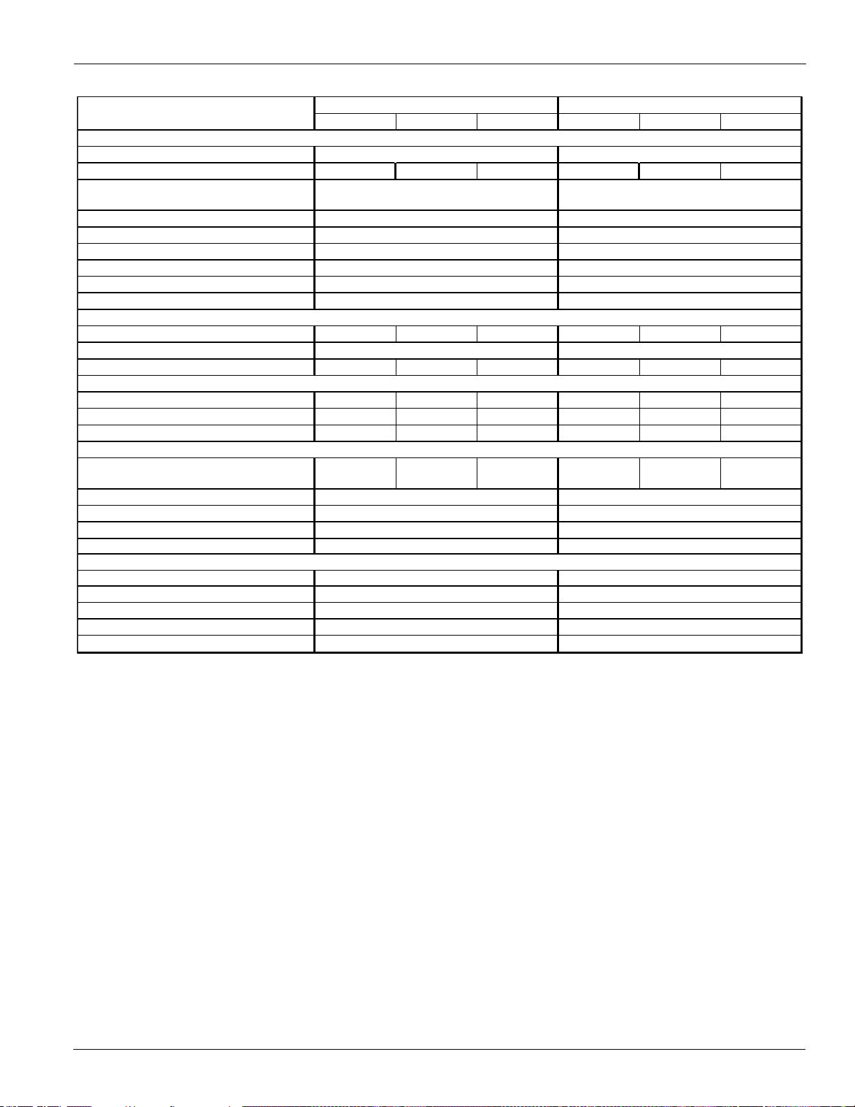
Table 14: Physical Data (60 Hz, Standard Efficiency, non-VFD models)
CIRCU IT 1 CIRCUIT 2 CIRC U IT 3 C IRC U IT 1 CIRCUIT 2 CIRC U IT 3
BASIC DATA
Unit Cap. @ AHRI t ons (kW)
Unit Operating Charge lbs (kg) 210 (95) 210 (95) 220 (100) 210 (95) 210 (95) 220 (100)
Unit Operating Weight, lbs. ( k g)
Unit S hipping W eight, lbs (kg)
Weight-Add for Copper Fins, lbs (kg)
g
Weight-Add for PFCC opt ion, lbs (kg)
COMPRESSOR S, SCR EW, SEMI-HER METI C
Nominal Capacity, tons (k W ) 135 (475) 155 (545) 155 (545) 155 (545) 155 (545) 155 (545)
Minimum Capacity (% of F ull Load)
Oil c har ge per c ir c uit , gallons (lit er s) 5.5 (21) 6 (23) 6 (23) 6 (23) 6 (23) 6 (23)
CONDENSERS, HIGH EFF ICIENCY FIN AND TUBE TYPE
Pumpdown Capacity, lbs (kg) 333 (151) 333 (151) 333 (151) 333 (151) 333 (151) 333 (151)
Coil Inlet F ac e Area, sq. f t. ( sq. m.) 196.9 (18.3) 196.9 ( 18.3) 196.9 ( 18.3) 196.9 ( 18.3) 196.9 ( 18.3) 196.9 ( 18.3)
Rows Deep/Fins Per Inch 3 / 16 3 / 16 3 / 16 3 / 16 3 / 16 3 / 16
CONDENSER FAN S, DIRECT DRIVE PROPELLER TYPE
Fan Motor, hp ( k W)
Fan & Motor RPM
Fan Tip Speed, f pm (m/s)
EVAPORATOR, DIRECT EXPANSION SHELL AND TUBE
Water Volume, gallons (liters)
Victaulic inlet /outlet c onn. in. ( mm)
Max. Water Pressure, psi (kPa)
Max. Refrigerant Press., psi (kPa)
25019 (11349)
3553 (1612)
25744 (11678)
3553 (1612)
Data
8888
88
776 (352)
225 (850)
26 x 130 / ( 660 x 3300)
220 (831)
6984 (35)
266040 (125556)
6984 (35)
266040 (125556)
26 x 130 / ( 660 x 3300)
325 (2241) 325 (2241)
10 (273)
152 (1048)
10 (273)
152 (1048)
8
1460 (662)
776 (352)
1460 (662)
8
1.4 ( 1.05)
850
1.4 ( 1.05)
850
459.2 ( 1615)
473 x 88 x 100
26418 (11984)
(12024 x 2225 x 2548)
27143 (12312)
(12024 x 2225 x 2548)
441.4 ( 1552)
473 x 88 x 100
AWS450BTS AWS470BTS
120 (55) 120 (55)
Note: A 20 mesh strainer must be placed in the supply water line just prior to the inlet of the evaporator.
Care must be exercised when welding pipe or flanges to the evaporator to prevent any slag from entering the vessel.
This information applies only to Rev 0B models of AWS-B. For Rev 00 models, consult CAT 600-6; Rev 0A, CAT 600-7.
Unit Dimensions
L x W x H, in. (mm)
Weight -Add f or Louvered Panels, lbs (kg)
Weight-Add for Sound Enclosures, lbs (k
Physical Data (non-VFD)
Number of F ans per Circ uit
Fan Diameter : 31. 5 in. (800 mm)
Airflow, cfm (l/s)
Shell Dia. - Tube Length, in.(mm)
IM 1167 19
Page 20
Physical Data (non-VFD)
CIRCU IT 1 C IRC U IT 2 C IRC U IT 3 CIRCUIT 1 CIRCU IT 2 CIRCUIT 3
BASIC DATA
Unit Cap. @ AHRI t ons (kW)
Unit Operating Charge lbs (kg) 210 (95) 210 (95) 280 (127) 265 (120) 265 (120) 220 (100)
Unit Operating W eight, lbs. (kg)
Unit S hipping Weight , lbs (kg)
Weight-Add for Copper Fins, lbs (kg)
Weight-Add for Louvered Panels, lbs (kg)
g
Weight-Add for PFCC opt ion, lbs (kg)
COMPRESSORS, SC REW, SE MI -HER MET I C
Nominal Capacity, tons (kW) 155 (545) 155 (545) 185 (650) 185 (650) 185 (650) 155 (545)
Minimum Capacity (% of F ull Load)
Oil c harge per c ircuit , gallons (liters) 6 (23) 6 (23) 6 (23) 6 (23) 6 (23) 6 (23)
CONDENSERS, HIGH EFF ICIENCY F IN AND TUBE TYPE
Pumpdown Capacity, lbs (kg) 333 (151) 333 (151) 416 (189) 416 (189) 416 (189) 333 (151)
Coil Inlet F ac e Area, sq. ft . (sq. m.) 196.9 (18.3) 196.9 ( 18.3) 246.1 ( 22.8) 246.1 ( 22.8) 246.1 (22.8) 196.9 (18. 3)
Rows Deep/Fins Per Inch 3 / 16 3 / 16 3 / 16 3 / 16 3 / 16 3 / 16
CONDENSER FANS, DIRECT DRIVE PROPELLER TYPE
Fan Motor, hp ( k W)
Fan & Motor RPM
Fan Tip Speed, fpm (m/s)
EVAPORATOR, DIRECT EXPANSION SHELL AND TUBE
Water Volume, gallons (liters)
Victaulic inlet/out let conn. in. ( mm)
M ax. Water Pressure, psi (kPa)
Max. Refrigerant Press., psi (kPa)
Data
509 x 88 x 100
517.7 ( 1820)
544 x 88 x 100
AWS500BTS AWS525BTS
4168 (1891)
1572 (713)
776 (352)
1684 (764)
776 (352)
(12921 x 2225 x 2548)
27902 (12657)
(13823 x 2225 x 2548)
28901 (13110)
6984 (35)
288210 (136019) 310380 (146482)
1.4 ( 1.05)
850
1.4 (1.05)
850
6984 (35)
10 (273)
152 (1048)
10 (273)
152 (1048)
26 x 130 / ( 660 x 3300)
220 (831)
26 x 130 / ( 660 x 3300)
220 (831)
325 (2241) 325 (2241)
88 8 10 10
88
120 (55)
27502 (12475)
120 (55)
26503 (12022)
3870 (1755)
488.3 ( 1717)
10
Note: A 20 mesh strainer must be placed in the supply water line just prior to the inlet of the evaporator.
Care must be exercised when welding pipe or flanges to the evaporator to prevent any slag from entering the vessel.
This information applies only to Rev 0B models of AWS-B. For Rev 00 models, consult CAT 600-6; Rev 0A, CAT 600-7.
Table 15: Physical Data (60 Hz, Standard Efficiency, non-VFD models)
Unit Dimensions
L x W x H, in. (mm)
Weight-Add for Sound E nc losures, lbs (k
Number of F ans per Circ uit
Fan Diameter : 31.5 in. (800 mm)
Airflow, cfm (l/s )
Shell Dia. - Tube Lengt h, in.(mm)
20 IM 1167
Page 21
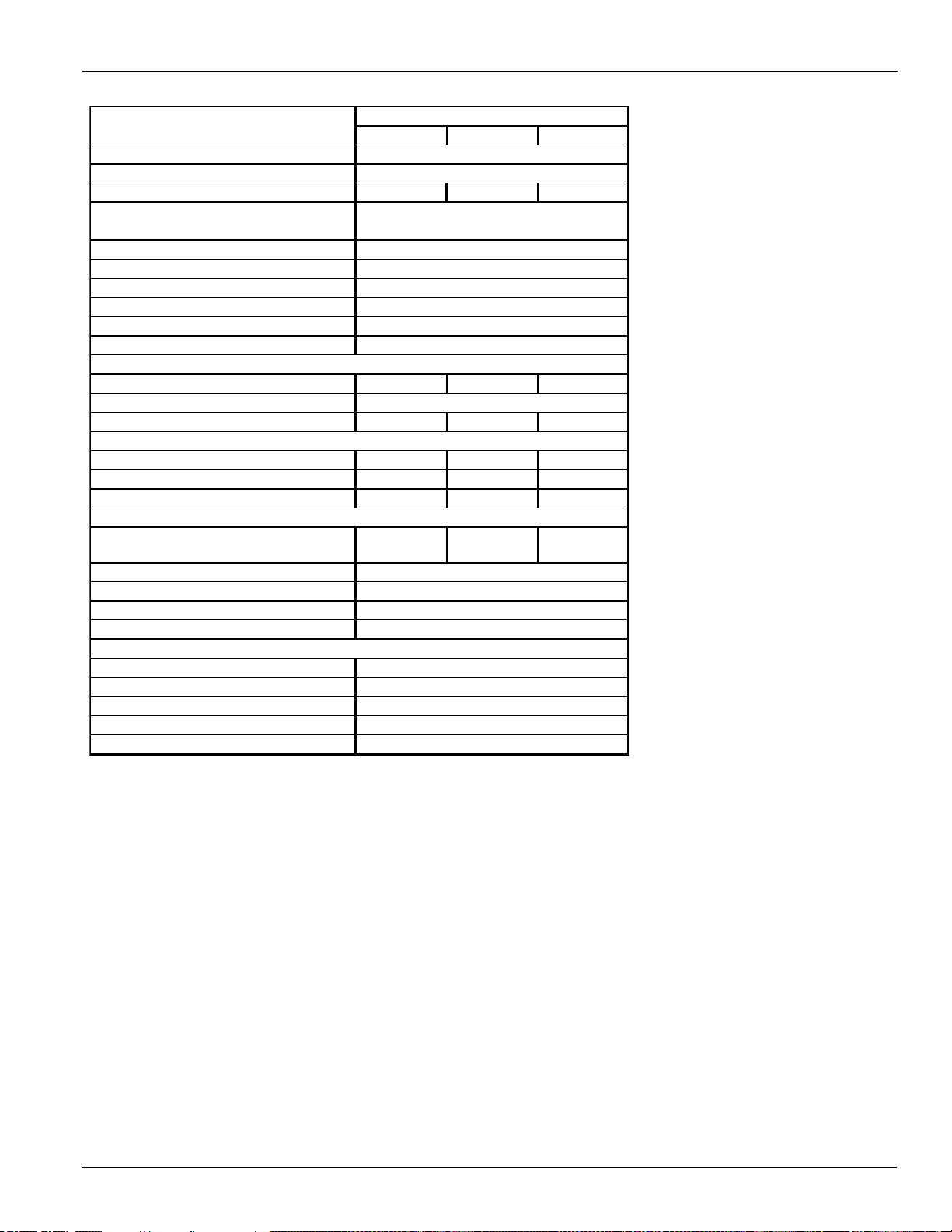
Table 16: Physical Data (60 Hz, Standard Efficiency, non-VFD models)
CIRCUIT 1 CIRCUIT 2 CIRCUIT 3
BASIC DATA
Unit Cap. @ AHRI tons (kW)
Unit O perat ing Charge lbs (kg) 270 (122) 270 (122) 280 (127)
Unit Dimensions
L x W x H, in. (mm)
Unit Oper at ing Weight , lbs. (k g)
Unit S hipping Weight , lbs (kg)
Weigh t -Add for Copper Fins, lbs (kg)
g
Weigh t - Add for PFCC opt ion, lbs (kg)
COMPRESSORS, SCREW, SEMI-HERMETIC
Nominal Capacity, to ns (kW) 185 (650) 185 (650) 185 (650)
Minimum Capacity (% of Full Load)
Oil c har ge pe r cir c uit , gallons (lit er s) 6 (2 3) 6 (23) 6 (23)
CONDENSERS, HIGH EFF ICIENCY F IN AND TUBE TYPE
Pumpdown Capacit y, lbs (kg) 416 (189) 416 (189) 416 (189)
Coil Inlet Fac e Area, sq. ft. (sq. m.) 246.1 (22. 8) 246. 1 (22.8) 246.1 ( 22. 8)
Rows Deep/F ins Per I nc h 3 / 16 3 / 16 3 / 16
CONDENSER FANS, DIRECT DRIVE PROPELLER TYPE
Fan Motor, hp ( kW)
Fan & Motor RPM
Fan Tip Speed, fpm (m/s)
A irflow, cfm (l/s)
EVAPORATOR, DIRECT EXPANSION SHELL AND TUBE
Shell Dia.-Tube Length, in. ( mm)
W ater Volume, gallo ns (lit e r s)
Victaulic inlet/outlet conn. in. (mm)
M ax. W ater Pressure, psi (kPa)
Max. Refrigerant Press., psi (kPa)
Data
AWS550BTS
(14722 x 2225 x 2548)
29643 (13446)
547.3 (1924)
580 x 88 x 100
1796 (815)
776 (352)
28244 (12812)
4466 (2026)
10 10 10
8
6984 (35)
332550 (156945)
1.4 (1. 05)
850
10 (273)
152 (1048)
26 x 130 / (660 x 3300)
220 (831)
325 (2241)
120 (55)
Note: A 20 mesh strainer must be placed in the supply water line just prior to the inlet of the evaporator.
Care must be exercised when welding pipe or flanges to the evaporator to prevent any slag from entering the vessel.
This information applies only to Rev 0B models of AWS-B. For Rev 00 models, consult CAT 600-6; Rev 0A, CAT 600-7.
Weigh t - Add for Louvered Panels, lbs (kg)
Weight -Add for Sound Enclosures, lbs (k
Physical Data (non-VFD)
Number of Fans per Circuit
Fan Diameter: 31. 5 in. (800 mm)
IM 1167 21
Page 22
Physical Data (non-VFD)
CIR C UIT 1 CIRC UIT 2 CIR C U IT 1 CIRC UIT 2 CIRC UIT 1 CIRCU IT 2
Unit Cap. @ AHRI tons (kW)
U nit Operating Charge lbs (kg)
160 (73) 160 (73) 180 (82) 180 (82) 180 (82) 180 (82)
Unit Dimensions
L x W x H, in. (mm)
Unit O perating Weight, lbs. (kg)
U nit Shipping Weight, lbs (kg)
W eight-Add for Copper F ins, lbs (kg)
g
W eight-Add for PF CC opt ion, lbs (kg)
N ominal Capacity, tons (kW)
105 (369) 105 (369) 105 (369) 125 (439) 125 (439) 125 (439)
Minimum Capacity (% of Full Load)
Oil charge per circuit , gallons (liters)
4.5 (17) 4.5 (17) 4.5 (17) 5.5 (21) 5.5 (21) 5.5 (21)
Pumpdown Capacity, lbs (kg)
250 (113) 250 (113) 291 (132) 291 (132) 291 (132) 291 (132)
Coil Inlet Fa ce Area, sq. ft. (sq. m.)
147.7 (13.7) 147.7 (13.7) 172.3 (16.0) 172.3 (16.0) 172.3 (16.0) 172.3 (16.0)
Row s Deep/Fins Per Inch
3 / 16 3 / 16 3 / 16 3 / 16 3 / 16 3 / 16
N umber of Fans per Circuit
Fan Diameter: 31.5 in. (800 m m)
Fan Motor, hp (kW)
Fan & Motor RPM
Fan Tip Spee d, fpm (m /s)
Airflow, cfm (l/s)
Shell Dia.-Tube Length, in.(m m)
Water Volume, gallons (liters)
Victaulic inl e t/o utl e t conn . i n . (mm)
Max. W ater Pressure , psi (kPa)
Max. Refrigerant P ress., psi (kP a)
BASIC DATA
COMPRESSORS, SCRE W , SE MI-HERMETIC
CONDENSERS, HIGH EFFICIENCY FIN AND TUBE TYPE
Data
AWS210BDH AWS230BDH AWS250BDH
15282 (6932)
205.7 (723) 225.2 (792) 240.6 (846)
245 x 88 x 100 280 x 88 x 100 280 x 88 x 100
15
788 (357) 900 (408)
(6220 x 2225 x 2548) (7121 x 2225 x 2548)
14622 (6633)
(7121 x 2225 x 2548)
13653 (6193) 15165 (6879) 15825 (7179)
777
1876 (851) 2084 (945) 2084 (945)
477 (216) 477 (216)
15 15
CONDENSER FANS, DIRECT DRIVE PROPELLER TYPE
1.4 (1.05) 1.4 (1.05) 1.4 (1.05)
850 850 850
667
6984 (35) 6984 (35) 6984 (35)
133020 (62778) 155190 (73241) 155190 (73241)
16 x 108 / (406 x 2750) 16 x 108 / (406 x 2750) 16 x 108 / (406 x 2750)
66 (251) 64 (243) 64 (243)
6 (168) 6 (168) 6 (168)
152 (1048) 152 (1048) 152 (1048)
325 (2241) 325 (2241) 325 (2241)
EVAPORATOR, DIRECT EXPANSION SHELL AND TUBE
477 (216)
13110 (5947)
160 (73) 160 (73) 160 (73)
900 (408)
Note: A 20 mesh strainer must be placed in the supply water line just prior to the inlet of the evaporator.
Care must be exercised when welding pipe or flanges to the evaporator to prevent any slag from entering the vessel.
This information applies only to Rev 0B models of AWS-B. For Rev 00 models, consult CAT 600-6; Rev 0A, CAT 600-7.
Table 17: Physical Data (60 Hz, High Efficiency, non-VFD models)
W eight-Add for Louv ered P anels, lbs (kg)
W eight-Add for Sound E nc losures, lbs (k
22 IM 1167
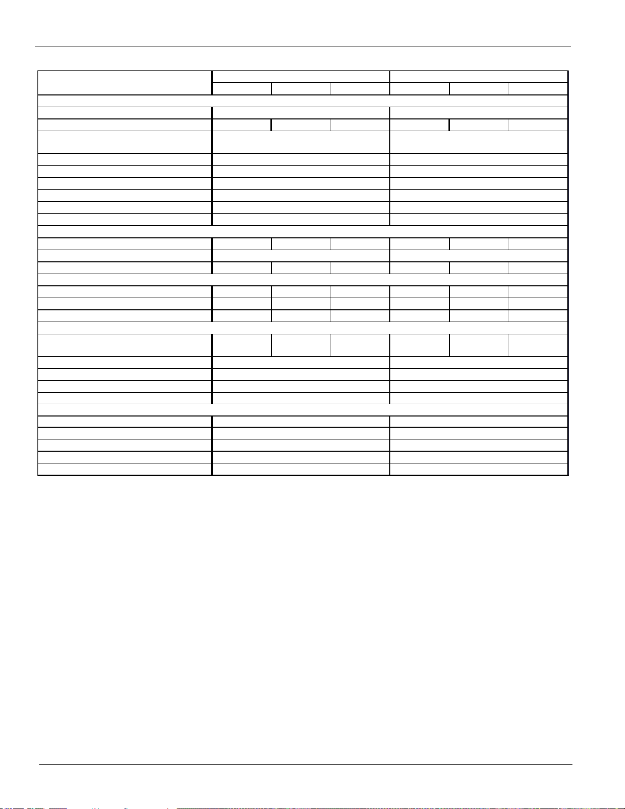
Page 23
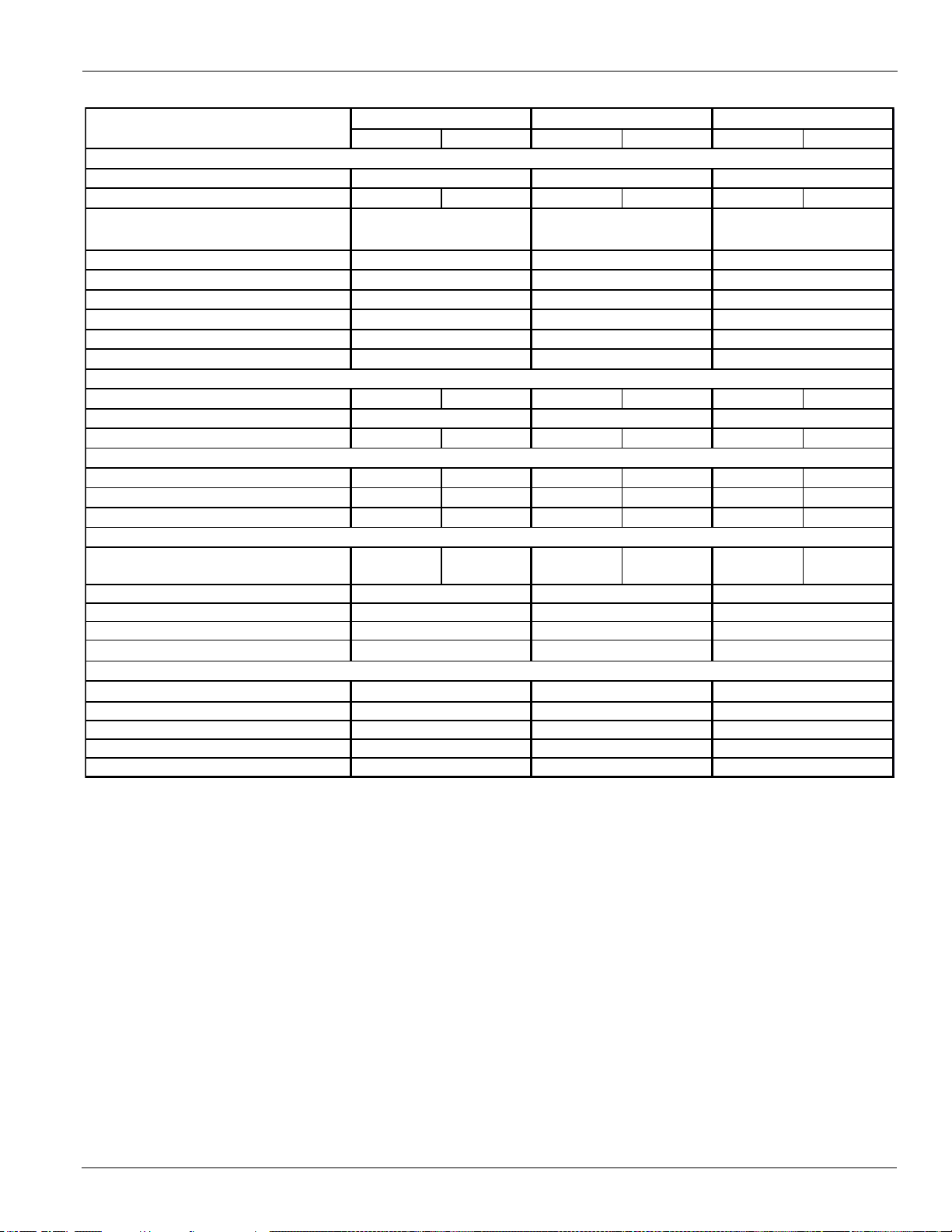
Table 18: Physical Data (60 Hz, High Efficiency, non-VFD models)
CIR C UIT 1 CIRC UIT 2 CIRCU IT 1 CIRCU IT 2 CIRCU IT 1 CIR C U IT 2
Unit Cap. @ AHRI tons (kW)
U nit Operating Charge lbs (kg)
230 (104) 250 (113) 250 (113) 250 (113) 260 (118) 285 (129)
Unit Dimensions
L x W x H, in. (mm)
U nit Operating Weight, lbs. (kg)
Unit Shipping W eight, lbs (kg)
W eight-Add for Copper F ins, lbs (kg)
W eight-Add for Louv ered P anels, lbs (kg)
g
W eight-Add for PF CC opt ion, lbs (kg)
N ominal Capacity, tons (kW)
125 (439) 150 (528) 150 (528) 150 (528) 150 (528) 175 (615)
Minimum Capacity (% of Full Load)
Oil charge per circuit , gallons (liters)
5.5 (21) 5.5 (21) 5.5 (21) 5.5 (21) 5.5 (21) 6 (23)
Pumpdown Capacity, lbs (kg)
333 (151) 333 (151) 333 (151) 333 (151) 416 (189) 416 (189)
Coil Inlet Fa ce Area, sq. ft. (sq. m.)
196.9 (18.3) 196.9 (18.3) 196.9 (18.3) 196.9 (18.3) 246.1 (22.8) 246.1 (22.8)
Row s Deep/Fins Per Inch
3 / 16 3 / 16 3 / 16 3 / 16 3 / 16 3 / 16
N umber of Fans per Circuit
Fan Diameter: 31.5 in. (800 m m)
Fan Motor, hp (kW)
Fan & Motor RPM
Fan Tip Speed, fpm (m/s)
Airflow, cfm (l/s)
Shell D i a.-Tube Length, in.(mm)
Water Volume, gallons (liters)
Victaulic inlet/outlet conn. in. (m m)
Max. Water Pressu re, psi (kPa)
Max. Refrigerant P ress., psi (kP a)
BASIC DATA
COMPRESSORS, SCRE W , SE MI-HERMETIC
CONDENSERS, HIGH EFFICIENCY FIN AND TUBE TYPE
CONDENSER FANS, DIRECT DRIVE PROPELLER TYPE
EVAPORATOR, DIRECT EXPANSION SHELL AND TUBE
Data
AWS280BDH AWS300BDH AWS330BDH
(9823 x 2225 x 2548)
17461 (7921) 17461 (7921) 19764 (8965)
271.9 (956) 288.7 (1015) 327.3 (1151)
316 x 88 x 100 316 x 88 x 100 387 x 88 x 100
1236 (561)
477 (216) 477 (216) 477 (216)
16594 (7527) 16594 (7527) 18897 (8572)
2372 (1076) 2372 (1076) 2968 (1346)
15 15 15
88881010
1.4 (1.05) 1.4 (1.05) 1.4 (1.05)
850 850 850
6984 (35) 6984 (35) 6984 (35)
177360 (83704) 177360 (83704) 221700 (104630)
20 x 108 / (508 x 2750) 20 x 108 / (508 x 2750) 20 x 108 / (508 x 2750)
107 (403) 107 (403) 102 (386)
8 (219) 8 (219) 8 (219)
152 (1048) 152 (1048) 152 (1048)
325 (2241) 325 (2241) 325 (2241)
160 (73) 160 (73) 160 (73)
1012 (459) 1012 (459)
(8022 x 2225 x 2548) (8022 x 2225 x 2548)
Note: A 20 mesh strainer must be placed in the supply water line just prior to the inlet of the evaporator.
Care must be exercised when welding pipe or flanges to the evaporator to prevent any slag from entering the vessel.
This information applies only to Rev 0B models of AWS-B. For Rev 00 models, consult CAT 600-6; Rev 0A, CAT 600-7.
W eight-Add for Sound Enc losures, lbs (k
Physical Data (non-VFD)
IM 1167 23
Page 24
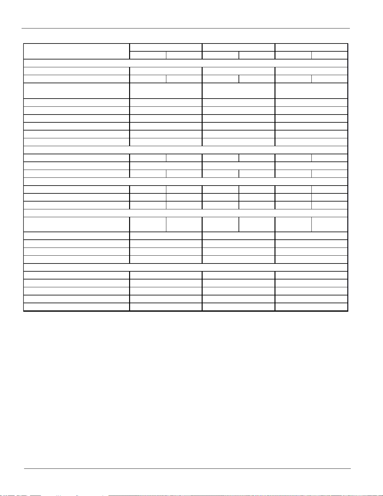
Physical Data (non-VFD)
CIR C U IT 1 CIRC U IT 2 CIRC U IT 1 CIRC U IT 2 CIRC U IT 1 CIRC U IT 2
Unit Cap. @ AHRI tons (kW)
Unit O perating Charge lbs (kg)
285 (129) 285 (129) 285 (129) 331 (150) 331 (150) 331 (150)
Unit Dimensions
L x W x H, in. (mm)
Unit Operating Weight, lbs. (kg)
Unit Shipping Weight, lbs (kg)
W eight-Add for Copper F ins, lbs (kg)
g
W eight-Add for PF CC opt ion, lbs (kg)
N ominal Capacity, tons (kW)
175 (615) 175 (615) 175 (615) 205 (721) 205 (721) 205 (721)
Minimum Capacity (% of Full Load)
Oil charge per circuit , gallons (liters)
6 (23) 6 (23) 6 (23) 6 (23) 6 (23) 6 (23)
Pumpdown Capacity, lbs (kg)
416 (189) 416 (189) 416 (189) 500 (227) 500 (227) 500 (227)
C o i l I n let Face Area, sq. ft. (sq. m.)
246.1 (22.8) 246.1 (22.8) 246.1 (22.8) 295.3 (27.4) 295.3 (27.4) 295.3 (27.4)
Row s Deep/Fins Per Inch
3 / 16 3 / 16 3 / 16 3 / 16 3 / 16 3 / 16
Number of Fans per Circuit
Fan Diameter: 31.5 in. (800 mm)
Fan Motor, hp (kW)
Fan & Motor RPM
Fan Tip Spee d, fpm (m/s)
Airflow, cfm (l/s)
Shell Dia.-Tube Length, in.(mm)
Water Volum e, gallons (liters)
Victaulic inle t/o u tl e t conn. i n . (mm)
Max. W ate r Pressure, p si (k Pa)
Max. Refrigerant Press., psi (kPa)
100 (377) 100 (377)
20 x 108 / (508 x 2750)
Data
AWS350BDH AWS390BDH AWS410BDH
348.1 (1224) 378.7 (1332) 409.8 (1441)
387 x 88 x 100 438 x 88 x 100 473 x 88 x 101
(9823 x 2225 x 2548) (11123 x 2225 x 2548) (12024 x 2225 x 2548)
20444 (9274) 21864 (9918) 22657 (10278)
19577 (8880) 20997 (9525) 21790 (9884)
2968 (1346) 3256 (1477) 3553 (1612)
1236 (561) 1348 (611) 1460 (662)
477 (216) 477 (216) 477 (216)
15 15 15
10 10 10 12 12 12
CONDENSERS, HIGH EFFICIENCY FIN AND TUBE TYPE
1.4 (1.05) 1.4 (1.05) 1.4 (1.05)
850 850 850
6984 (35) 6984 (35) 6984 (35)
221700 (104630) 243870 (115094) 266040 (125556)
102 (386)
8 (219) 8 (219) 8 (219)
152 (1048) 152 (1048) 152 (1048)
325 (2241) 325 (2241) 325 (2241)
20 x 108 / (508 x 2750) 20 x 108 / (508 x 2750)
BASIC DATA
COMPRESSORS, SCRE W , SEMI-HE RMETIC
CONDENSER FANS, DIRECT DRIVE PROPELLER TYPE
EVAPORATOR, DIRECT EXPANSION SHELL AND TUBE
160 (73) 160 (73) 160 (73)
Note: A 20 mesh strainer must be placed in the supply water line just prior to the inlet of the evaporator.
Care must be exercised when welding pipe or flanges to the evaporator to prevent any slag from entering the vessel.
This information applies only to Rev 0B models of AWS-B. For Rev 00 models, consult CAT 600-6; Rev 0A, CAT 600-7.
Table 19: Physical Data (60 Hz, High Efficiency, non-VFD models)
W eight-Add for Louvered P anels, lbs (kg)
W eight-Add for Sound E nc losures, lbs (k
24 IM 1167
Page 25
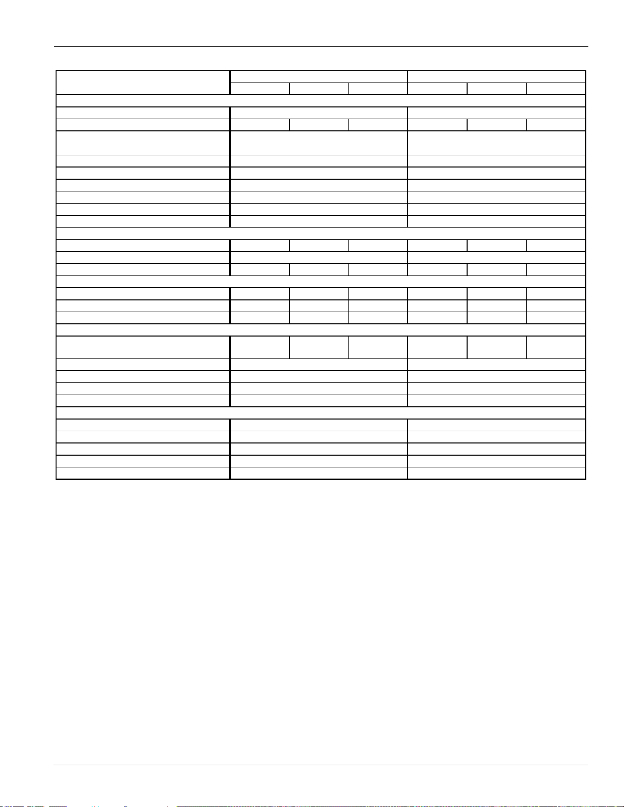
Table 20: Physical Data (60 Hz, High Efficiency, non-VFD models)
CIRCU IT 1 CIRCUIT 2 C IRC U IT 3 CIRCUIT 1 CIR C U IT 2 CIRCUIT 3
Unit Cap. @ AHRI tons (kW)
Unit Operating Charge lbs (kg)
250 (113) 250 (113) 250 (113) 250 (113) 250 (113) 295 (134)
Unit Dimensions
L x W x H, in. (mm)
Unit Operating Weight, lbs. (kg)
Unit Shipping Weight, lbs (kg)
Weight -Add f or Copper Fins, lbs (kg)
Weight -Add f or Louvered Panels, lbs (kg)
g
Weight -Add f or P FCC opt ion, lbs (kg)
Nominal C apacity, tons (kW)
150 (528) 150 (528) 150 (528) 150 (528) 150 (528) 175 (615)
Minimum Capacity (% of Full Load)
Oil charge per circuit , gallons (liters)
5.5 (21) 5.5 (21) 5.5 (21) 5.5 (21) 5.5 (21) 6 (23)
Pumpdow n Capacity, lbs (kg)
333 (151) 333 (151) 333 (151) 333 (151) 333 (151) 416 (189)
Coil Inlet Face Area, sq. ft. (sq. m.)
196.9 (18.3) 196.9 (18.3) 196.9 (18.3) 196.9 (18.3) 196.9 (18.3) 246.1 (22.8)
Row s Deep/Fins Per Inch
3 / 16 3 / 16 3 / 16 3 / 16 3 / 16 3 / 16
Number of Fans per Circuit
Fan Diameter: 31.5 in. (800 m m)
Fan Motor, hp (kW)
Fan & Motor RPM
Fan Tip Speed, fpm (m/s)
Airflow, cfm (l/s)
Shell Dia.-Tube Length, in.(mm)
Water Volume, gallons (liters)
Victaulic inlet/outlet conn. in. (mm)
Max. Water Pressure, psi (kPa)
Max. Refrigerant Press., psi (kPa)
88810
6984 (35)
AWS450BTH
BASIC DATA
COMPRESSORS, SCREW, SEMI-HERMETIC
Data
AWS475BTH
446.3 ( 1569)
473 x 88 x 100
470.3 ( 1654)
509 x 88 x 100
24658 (11185)
3553 (1612)
26143 (11859)
3870 (1755)
776 (352)
(12024 x 2225 x 2548)
26057 (11820)
(12921 x 2225 x 2548)
27542 (12493)
8
1.4 (1.05)
8
1.4 (1.05)
1572 (713)
776 (352)
CONDENSERS, HIGH EFFICIENCY FIN AND TUBE TYPE
CONDENSER FANS, DIRECT DRIVE PROPELLER TYPE
88
10 (273)
152 (1048)
10 (273)
152 (1048)
288210 (136019)
26 x 130 / (660 x 3300)
225 (850)
26 x 130 / (660 x 3300)
220 (831)
850 850
6984 (35)
266040 (125556)
EVAPORATOR, DIRECT EXPANSION SHELL AND TUBE
325 (2241)325 (2241)
120 (55)
1460 (662)
120 (55)
Note: A 20 mesh strainer must be placed in the supply water line just prior to the inlet of the evaporator.
Care must be exercised when welding pipe or flanges to the evaporator to prevent any slag from entering the vessel.
This information applies only to Rev 0B models of AWS-B. For Rev 00 models, consult CAT 600-6; Rev 0A, CAT 600-7 .
Weight -Add f or S ound E nc losures, lbs (k
Physical Data (non-VFD)
IM 1167 25
Page 26
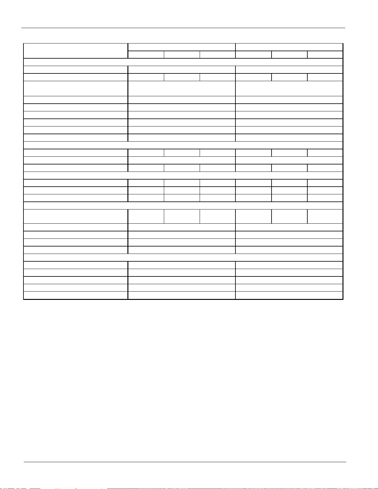
Physical Data (non-VFD)
CIRCUIT 1 CIRCUIT 2 CIRCUIT 3 CIRCUIT 1 CIRCUIT 2 CIRCUIT 3
BASIC DATA
U n it Cap. @ AH RI tons (kW)
U nit Operating Charge lbs (kg)
295 (134) 295 (134) 250 (113) 295 (134) 295 (134) 295 (134)
Unit Dimensions
L x W x H, in. (mm)
Unit Operating Weight, lbs. (kg)
Unit Shipping Weight, lbs (kg)
Weight - Add for Copper Fins, lbs (kg)
g
Weight - Add for PFCC opt ion, lbs (kg)
COMPRESSORS, SCREW, SEMI-HERMETI C
Nominal Capacity, tons (kW) 175 (615) 175 (615) 150 (528) 175 (615) 175 (615) 175 (615)
Minimum Capacity (% of Full Load)
Oil charge per circuit , gallons (liters) 6 (23) 6 (23) 5.5 (21) 6 (23) 6 (23) 6 (23)
CONDENSERS, HIGH EFFICIENCY FIN AND TUBE TYPE
Pumpdown Capacity, lbs (kg) 416 (189) 416 (189) 333 (151) 416 (189) 416 (189) 416 (189)
Coi l Inlet Face Area, sq. ft. (sq. m.) 246.1 (22.8) 246.1 (22.8) 196.9 (18.3) 246.1 (22.8) 246.1 (22.8) 246.1 (22.8)
R o ws Deep/Fins Per Inch 3 / 16 3 / 16 3 / 16 3 / 16 3 / 16 3 / 16
CONDENSER FANS, DIRECT DRIVE PROPELLER TYPE
Number of Fans per Circuit
Fan Diam e te r: 31.5 i n . (800 mm)
Fan Motor, hp (kW)
Fan & Motor RPM
Fan Tip Speed, fpm (m/s)
Airflow, cfm (l/s)
EVAPORATOR, DIRECT EXPANSION SHELL AND TUBE
Shell Dia.-Tube Length, in.(m m)
Water Volume, gallons (liters)
Victaulic inlet/outlet conn. in. (m m)
Max. Water Pressure, psi (kPa)
Max. Refrigerant Press., psi (kPa)
(14722 x 2225 x 2548)
8
30608 (13884)
29209 (13249)
4466 (2026)
1796 (815)
776 (352)
528.3 (18 57)
580 x 88 x 100
Data
AWS500BTH AWS530BTH
(13823 x 2225 x 2548)
29181 (13237)
499.4 (1756 )
544 x 88 x 100
27782 (12602)
4168 (1891)
10 10
1684 (764)
776 (352)
8
1.4 (1.05) 1.4 (1.05)
10 10 8
152 (1048)
26 x 130 / (660 x 3300)
220 (831)
26 x 130 / (660 x 3300)
220 (831)
6984 (35) 6984 (35)
310380 (146482)
152 (1048)
10 (273) 10 (273)
10
850 850
332550 (156945)
325 (2241)325 (2241)
120 (55) 120 (55)
Note: A 20 mesh strainer must be placed in the supply water line just prior to the inlet of the evaporator.
Care must be exercised when welding pipe or flanges to the evaporator to prevent any slag from entering the vessel.
This information applies only to Rev 0B models of AWS-B. For Rev 00 models, consult CAT 600-6; Rev 0A, CAT 600-7.
Table 21: Physical Data (60 Hz, High Efficiency, non-VFD models)
Weight - Add for Louvered Panels, lbs (kg)
Weight - Add for Sound E nc losures, lbs (k
26 IM 1167
Page 27
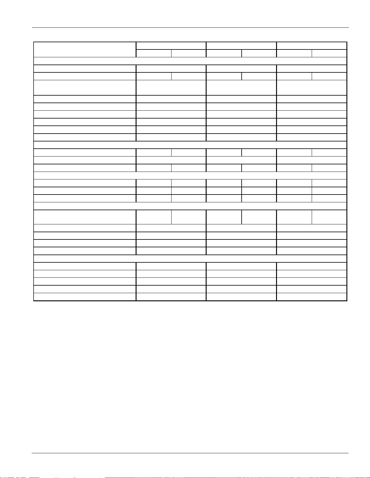
Table 22: Physical Data (60 Hz, Premium Efficiency, non-VFD models)
CIR C U IT 1 CIRC U IT 2 CIRCU IT 1 CIRC U IT 2 CIRC U IT 1 CIRCU IT 2
Unit Cap. @ AHRI tons (kW)
Unit O perating Charge lbs (kg)
200 (91) 200 (91) 225 (102) 225 (102) (235) (107) (235) (107)
Unit Dimensions
L x W x H, in. (mm)
Unit O perating Weight, lbs. (kg)
Unit Shipping W eight, lbs (kg)
W eight-Add for Copper F ins, lbs (kg)
g
W eight-Add for PF CC option, lbs (kg)
N ominal Capacity, tons (kW)
105 (369) 105 (369) 105 (369) 125 (439) 125 (439) 125 (439)
Minimum Capacity (% of Full Load)
Oil charge per circuit , gallons (liters)
4.5 (17) 4.5 (17) 4.5 (17) 5.5 (21) 5.5 (21) 5.5 (21)
Pumpdown Capacity, lbs (kg)
333 (151) 333 (151) 375 (170) 375 (170) 375 (170) 375 (170)
Coil Inlet Fa ce Area, sq. ft. (sq. m.)
196.9 (18.3) 196.9 (18.3) 221.5 (20.6) 221.5 (20.6) 221.5 (20.6) 221.5 (20.6)
Row s Deep/Fins Per Inch
3 / 16 3 / 16 3 / 16 3 / 16 3 / 16 3 / 16
Number of Fans per Ci rcuit
Fan Diameter: 31.5 in. (800 m m)
Fan Motor, hp (kW)
Fan & Motor RPM
Fan Tip Spee d, fpm (m/s)
Airflow, cfm (l/s)
Shell Dia.-Tube Length, in.(m m)
Water Volume, gallons (liters)
Victaulic inl et/o u tl e t conn . i n . (mm)
Max. W ate r Pressure, psi (kPa)
Max. Refrigerant Press., psi (kPa)
BASIC DATA
COMPRESSORS, SCRE W , SEMI-HE RMETIC
CONDENSERS, HIGH EFFICIENCY FIN AND TUBE TYPE
152 (1048) 152 (1048) 152 (1048)
325 (2241) 325 (2241) 325 (2241)
158 (599) 158 (599) 276 (1043)
8 (2199 8 (219) 10 (273)
177360 (83704) 199530 (94167) 199530 (94167)
20 x 154 / (508 x 3900) 20 x 154 / (508 x 3900) 26 x 154 / (660 x 3900)
EVAPORATOR, DIRECT EXPANSION SHELL AND TUBE
850 850 850
6984 (35) 6984 (35) 6984 (35)
99
CONDENSER FANS, DIRECT DRIVE PROPELLER TYPE
1.4 (1.05) 1.4 (1.05) 1.4 (1.05)
8899
477 (216) 477 (216) 477 (216)
15 15 15
2372 (1076) 2679 (1215) 2679 (1215)
1012 (459) 1124 (510) 1124 (510)
17210 (7807) 18631 (8451) 20722 (9400)
15958 (7239) 17379 (7883) 19069 (8650)
316 x 88 x 100 351 x 88 x 100 351 x 88 x 100
(8022 x 2225 x 2548) (8923 x 2225 x 2548) (8923 x 2225 x 2548)
Data
AWS240BDP AWS265BDP AWS290BDP
256.4 (901) 277.5 (976)232.8 (818)
160 (73) 160 (73) 160 (73)
Note: A 20 mesh strainer must be placed in the supply water line just prior to the inlet of the evaporator.
Care must be exercised when welding pipe or flanges to the evaporator to prevent any slag from entering the vessel.
This information applies only to Rev 0B models of AWS-B. For Rev 00 models, consult CAT 600-6; Rev 0A, CAT 600-7.
W eight-Add for Louv er ed Panels, lbs (kg)
W eight-Add for Sound E nc losures, lbs (k
Physical Data (non-VFD)
IM 1167 27
Page 28
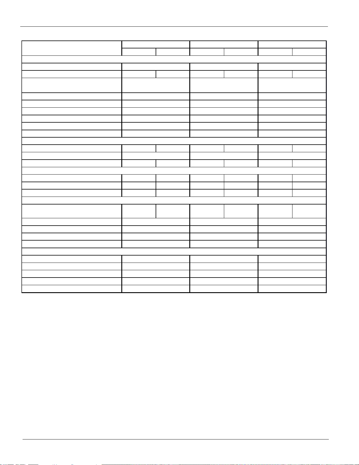
Physical Data (non-VFD)
CIR C U IT 1 CIRC U IT 2 CIRCU IT 1 CIRC U IT 2 CIRC U IT 1 CIRC UIT 2
Unit Cap. @ AHRI tons (kW)
U nit Operating Charge lbs (kg)
250 (113) 250 (113) 260 (118) 260 (118) 260 (118) 300 (136)
Unit Dimensions
L x W x H , in. (mm)
U nit Operating Weight, lbs. (kg)
Unit Shipping Weight, lbs (kg)
W eight-Add for Copper F ins, lbs (kg)
W eight-Add for Louv er ed Panels, lbs (kg)
g
W eight-Add for PF CC option, lbs (kg)
N ominal Capacity, tons (kW)
125 (439) 150 (528) 150 (528) 150 (528) 150 (528) 175 (615)
Minimum Capacity (% of Full Load)
Oil charge per circuit , gallons (liters)
5.5 (21) 5.5 (21) 5.5 (21) 5.5 (21) 5.5 (21) 6 (23)
Pumpdown Capacity, lbs (kg)
416 (189) 416 (189) 416 (189) 416 (189) 416 (189) 500 (227)
Coil Inlet Fa ce Area, sq. ft. (sq. m.)
246.1 (22.8) 246.1 (22.8) 246.1 (22.8) 246.1 (22.8) 246.1 (22.8) 295.3 (27.4)
Row s Deep/Fins Per Inch
3 / 16 3 / 16 3 / 16 3 / 16 3 / 16 3 / 16
N umber of Fans per Circuit
Fan Diameter: 31.5 in. (800 m m)
Fan Motor, hp (kW)
Fan & Motor RPM
Fan Tip Speed, fpm (m/s)
Airflow, cfm (l/s)
Shell D i a.-Tube Length, in.(mm)
Water Volume, gallons (liters)
Victaulic inlet/outlet conn. in. (mm)
Max. Wate r Pressure , psi (kPa)
Max. Refrigerant Press., psi (kPa)
152 (1048) 152 (1048) 152 (1048)
325 (2241) 325 (2241) 325 (2241)
276 (1043) 259 (979) 259 (979)
10 (273) 10 (273) 10 (273)
221700 (104630) 221700 (104630) 243870 (115093)
26 x 154 / (660 x 3900) 26 x 154 / (660 x 3900) 26 x 154 / (660 x 3900)
EVAPORATOR, DIRECT EXPANSION SHELL AND TUBE
850 850 850
6984 (35) 6984 (35) 6984 (35)
10 12
1.4 (1.05) 1.4 (1.05) 1.4 (1.05)
10 10 10 10
15 15 15
COMPRESSORS, SCRE W , SE MI-HERMETIC
160 (73)160 (73)
1236 (561) 1236 (561) 1348 (611)
477 (216) 477 (216) 477 (216)
21559 (9779) 23659 (10732)
19906 (9030) 19906 (9030) 22006 (9982)
2968 (1346) 2968 (1346) 3256 (1477)
CONDENSER FANS, DIRECT DRIVE PROPELLER TYPE
AWS310BDP AWS330BDP AWS365BDP
303.9 (1068) 324.9 (1142) 355 (1248)
BASIC DATA
387 x 88 x 100
21559 (9779)
Dat a
CONDENSERS, HIGH EFFICIENCY FIN AND TUBE TYPE
387 x 88 x 100 438 x 88 x 100
9823 x 2225 x 2545 9823 x 2225 x 2545 11123 x 2225 x 2548
160 (73)
Note: A 20 mesh strainer must be placed in the supply water line just prior to the inlet of the evaporator.
Care must be exercised when welding pipe or flanges to the evaporator to prevent any slag from entering the vessel.
This information applies only to Rev 0B models of AWS-B. For Rev 00 models, consult CAT 600-6; Rev 0A, CAT 600-7.
Table 23: Physical Data (60 Hz, Premium Efficiency, non-VFD models)
W eight-Add for Sound E nclosures, lbs (k
28 IM 1167
Page 29
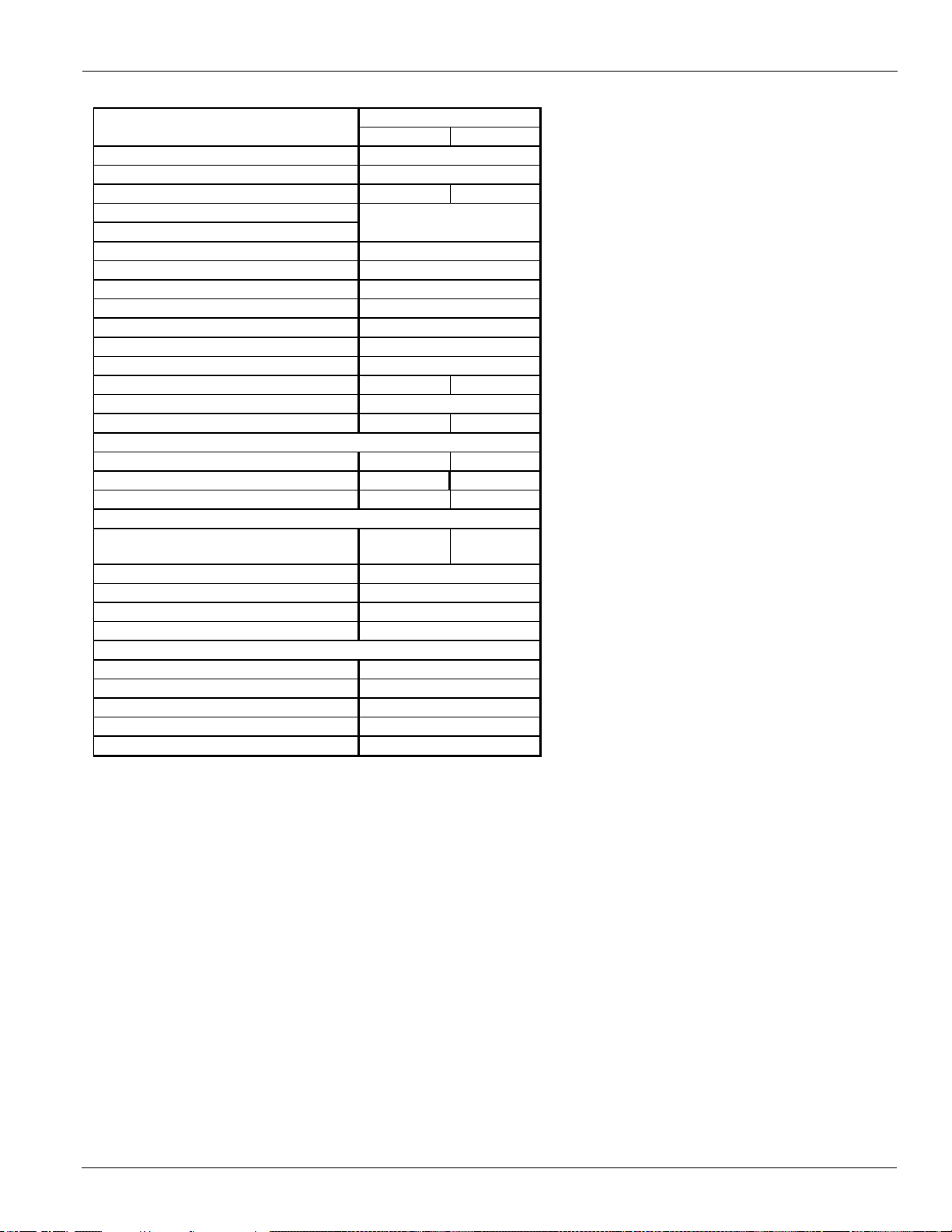
Table 24: Physical Data (60 Hz, Premium Efficiency, non-VFD models)
CIRCUIT 1 CIRCUIT 2
BASIC DATA
U ni t Cap. @ AHRI tons (kW)
U nit Operating C harge lbs (kg)
310 (141) 310 (141)
U ni t Dimensions
L x W x H, in. (mm)
U ni t Operating Weight, lbs. (kg)
U ni t S hi ppi ng Weight, lbs (kg)
Weight -Add for Copper F ins, lbs (kg)
g
Weight - Add for PF CC opt ion, lbs (kg)
COMPRESSO RS, SCREW, SEMI-HERMETIC
N ominal Capacity, tons (kW)
175 (615) 175 (615)
Minimum Capacity (% of Full Load)
Oil charge per circuit , gallons (liters)
6 (23) 6 (23)
CONDENS ERS , HIGH EFFICIENCY FIN AND TU BE TYPE
Pumpdown Capacity, lbs (kg)
500 (227) 500 (227)
Coil Inle t Face Area, sq. ft. (sq. m.)
295.3 (27.4) 295.3 (27.4)
R ows Deep/Fins Per Inch
3 / 16 3 / 16
CONDENSER FANS, DIRECT DRIV E PROPELLER TYPE
N umber of Fans per Circuit
Fan Diameter: 31.5 in. (800 mm)
Fan Motor, hp (kW)
Fan & Motor RPM
Fan Tip Speed, fpm (m/s)
Airflow, cfm (l/s)
EVAPORATOR, DIRECT EXPANSION SHELL AND TUBE
Shell Dia.-Tube Length, in.(mm)
Water Volume, gallons (liters)
Victaulic inlet/outlet conn. in. (mm)
Max. Water Pressure, p si (kPa)
Max. Refrigerant Press., psi (kPa)
325 (2241)
259 (979)
10 (273)
152 (1048)
6984 (35)
266040 (125556)
26 x 154 / (660 x 3900)
1.4 (1. 05)
850
477 (216)
15
12 12
23440 (10633)
3553 (1612)
1460 (662)
473 x 88 x 100
(12024 x 2225 x 2548)
25093 (11382)
Data
AWS400BDP
385.4 (1355)
160 (73)
Note: A 20 mesh strainer must be placed in the supply water line just prior to the inlet of the evaporator.
Care must be exercised when welding pipe or flanges to the evaporator to prevent any slag from entering the vessel.
This information applies only to Rev 0B models of AWS-B. For Rev 00 models, consult CAT 600-6; Rev 0A, CAT 600-7.
Weight -Add for Louv er ed Panels, lbs (kg)
Weig ht - Add for S o und E nc losures, lbs (k
Physical Data (non-VFD)
IM 1167 29
Page 30
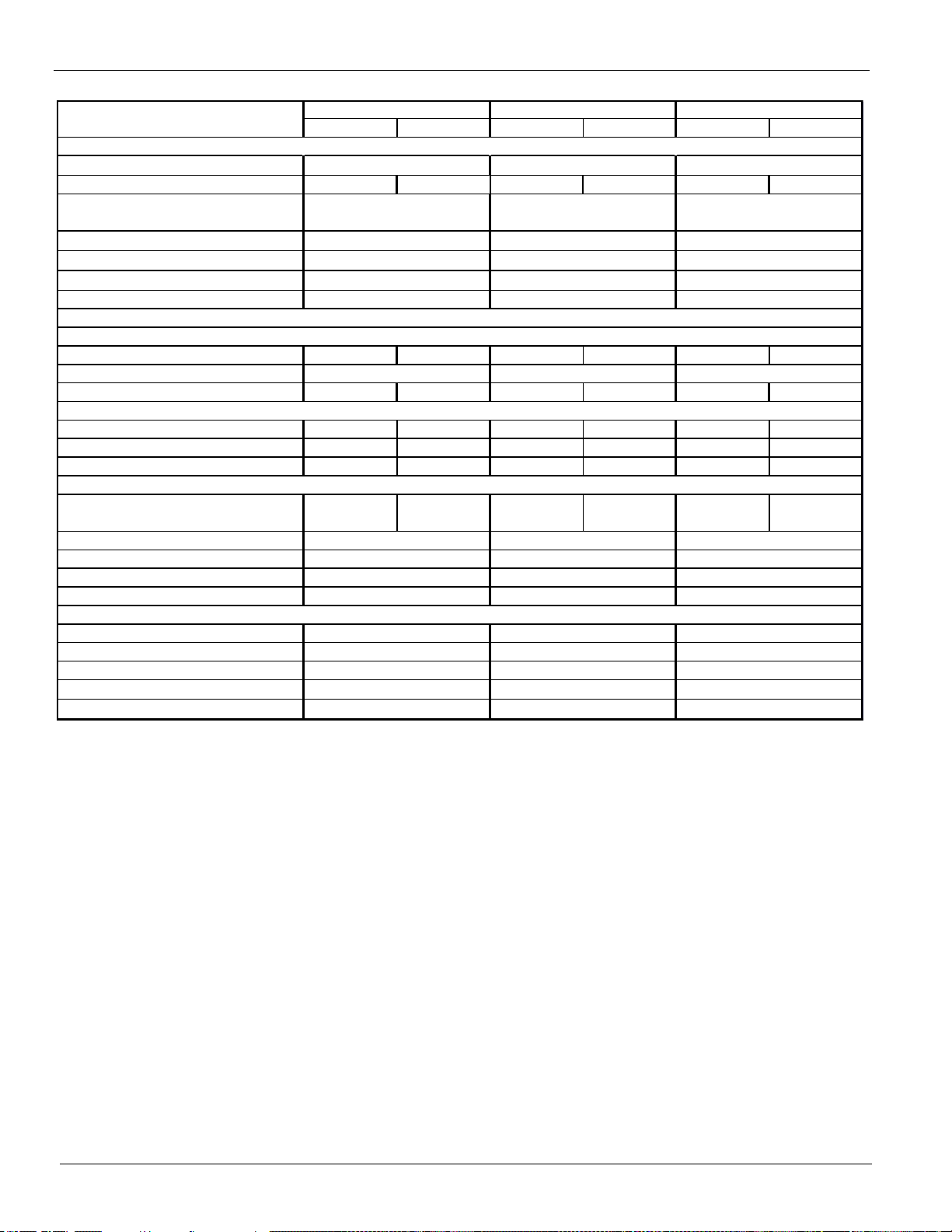
Physical Data (VFD)
CIRCUIT 1 CIRCUIT 2 CIRCUIT 1 CIRCUIT 2 CIRCUIT 1 CIRCUIT 2
Unit Cap. @ A HRI tons (kW)
U nit Operating Charge lbs (kg)
145 (66) 145 (66) 165 (75) 165 (75) 165 (75) 165 (75)
Unit Dimensions
L x W x H, in. (mm)
U nit Operating Weight, lbs. (kg)
Unit Shipping Weight, lbs (kg)
Weight-Add for Copper Fins
Weight-Add for Louvered Panel s
Nominal Capacity, tons (kW )
95 (334) 95 (334) 95 (334) 115 (404) 115 (404) 115 (404)
Minimum Capacity (% of Full Load)
Oil charge per circuit , gallons (liters)
4.5 (17) 4.5 (17) 4.5 (17) 5.5 (21) 5.5 (21) 5.5 (21)
Pumpdown C a p a city, lb s (kg)
208 (94) 208 (94)
250 (113) 250 (113) 250 (113) 250 (113)
Coil Inlet F a ce Area, sq. ft. (sq. m.)
123.1 (11.4) 123.1 (11.4)
147.7 (13.7) 147.7 (13.7) 147.7 (13.7) 147.7 (13.7)
Row s Deep/Fins Per Inch
3 / 16 3 / 16
3 / 16 3 / 16 3 / 16 3 / 16
N umber of Fans per Circuit
Fan Diameter: 31.5 in. (800 mm)
F a n Motor, hp (kW)
Fan & Motor RPM
Fan Tip Speed, fpm (m/s)
Airflo w, cfm (l/s)
Shell D ia.-Tube Length, in.(mm)
Water Volume, gallons (liters)
Victaulic in l e t/o u tl e t conn . i n . (mm)
Max. W ater Pressure, psi (k Pa)
Max. Refrigerant P ress., psi (kP a)
268 x 88 x 100 268 x 88 x 100 268 x 88 x 100
(6803 x 2225 x 2548) (6803 x 2225 x 2548) (6803 x 2225 x 2548)
14130 (6409) 15435 (7001) 15359 (6967)
14673 (6656) 15978 (7248) 15902 (7213)
6666
CONDENSERS, HIGH EFFICIENCY FIN AND TUBE TYPE
20 20 20
325 (2241) 325 (2241) 325 (2241)
68 (258) 68 (258) 66 (251)
6 (168) 6 (168) 6 (168)
152 (1048) 152 (1048) 152 (1048)
CONDENSER FANS, DIRECT DRIVE PROPELLER TYPE
55
Dat a
BASIC DATA
162.6 (572) 181.3 (637) 195.1 (686)
A
1776 (806) 1776 (806) 1776 (806)
COMPRESSOR S, SCREW, SE MI-HERMETIC
676 (307) 788 (357) 788 (357)
1.4 (1.05) 1. 4 (1. 05) 1. 4 (1. 05)
850 850 850
16 x 108 (406 x 2750) 16 x 108 ( 406 x 2750) 16 x 108 (406 x 2750)
6984 (35) 6984 (35) 6984 (35)
EVAPORATOR, DIRECT EXPANSION SHELL AND TUBE
110850 (52315) 133020 (62778) 133020 (62778)
Note: A 20 mesh strainer must be placed in the supply water line just prior to the inlet of the evaporator.
Care must be exercised when welding pipe or flanges to the evaporator to prevent any slag from entering the vessel.
This information applies only to Rev 0B models of AWS-B. For Rev 00 models, co nsult CAT 600-6; Rev 0A, CAT 600-7.
Physical Data (VFD)
Table 25: Physical Data (60 Hz, Standard Efficiency, VFD models)
AWS170BDS VFD
WS190B DS VFD A WS 200BDS V FD
30 IM 1167
Page 31

Table 26: Physical Data (60 Hz, High Efficiency, VFD models)
Unit Cap. @ AHRI tons (kW)
U nit Operating Charge lbs (kg) 160 (73) 160 (73) 180 (82) 180 (82) 180 (82) 180 (82)
U nit D imensions
L x W x H, i n . (mm)
U nit Operating Weight, lbs. (kg)
U nit Shipping Weight, lbs (kg)
W eight-Add for Copper Fins
W eight-Add for Louvered P anels
N ominal C apacity, tons (kW ) 105 (369) 105 (369) 105 (369) 125 (439) 125 (439) 125 (439)
Minimum Capacity (% of Full Load)
Oil charge per circuit , gallons (liters) 4.5 (17) 4.5 (17) 4.5 (17) 5.5 (21) 5.5 (21) 5.5 (21)
P umpdown C apacity, lbs (kg) 250 (113) 250 (113) 291 (132) 291 (132) 291 (132) 291 (132)
C oil Inlet Face Area, sq. ft. (sq. m.) 147.7 (13.7) 147.7 (13.7) 172.3 (16.0) 172.3 (16.0) 172.3 (16.0) 172.3 (16.0)
R ows D eep/Fins P er Inch 3 / 16 3 / 16 3 / 16 3 / 16 3 / 16 3 / 16
N umber of Fans per Circuit
Fan Diameter: 31.5 in. (800 mm)
Fan Motor, hp (kW )
Fan & Motor RP M
Fan T ip S peed, fpm (m /s)
Ai rflo w, cfm (l/s)
Shell D ia.-Tube Length, in.(mm)
W ater Volume, gallons (liters)
Victaulic inlet/outlet conn. in. (mm)
Max. W a te r Pressure, p si (k Pa)
Max. Re frigera n t Press., psi (k Pa)
6 (168)
325 (2241) 325 (2241) 325 (2241)
152 (1048) 152 (1048) 152 (1048)
66 (251) 64 (243) 64 (243)
16 x 108 / (406 x 2750) 16 x 108 / (406 x 2750)
1.4 (1.05)
6984 (35) 6984 (35) 6984 (35)
COMPRESSO R S, SCREW , SEMI-HE R METIC
CONDENSERS, HIGH EFFI CIENCY FIN AND TUBE TYPE
788 (357) 900 (408) 900 (408)
2084 (945)
14603 (6624) 15935 (7228) 16478 (7474)
1876 (851) 2084 (945)
268 x 88 x 100 303 x 88 x 100
15146 (6870) 16478 (7474) 17021 (7721)
303 x 88 x 100
BASI C DATA
205.2 (721) 224.8 (790) 240.0 (844)
Data
A
20 20 20
CONDENSER FANS, DI RECT DRI VE PROPELLER TYPE
667777
850 850 850
1.4 (1.05) 1.4 (1.05)
EVAPORATOR, DIRECT EXPANSION SHELL AND TUBE
16 x 108 / (406 x 2750)
6 (168) 6 (168)
Note: A 20 mesh strainer must be placed in the supply water line just prior to the inlet of the evaporator.
Care must be exercised when welding pipe or flanges to the evaporator to prevent any slag from entering the vessel.
This information applies only to Rev 0B models of AWS-B. For Rev 00 models, co nsult CAT 600-6; Rev 0A, CAT 600-7.
Physical Data (VFD)
AWS210BDH VFD
WS230BDH VFD AWS250BDH VFD
CIRCUIT 1 CIRCUIT 2 CIRCUIT 1 CIRCUIT 2 CIRCUIT 1 CIRCUIT 2
6803 x 2225 x 2548 7703 x 2225 x 2548 7703 x 2225 x 2548
IM 1167 31
133020 (62778) 155190 (73241) 155190 (73241)
Page 32

Physical Data (VFD)
Unit Cap. @ AHRI tons (kW)
Unit Operating Charge lbs (kg) 200 (91) 200 (91) 210 (95) 210 (95) 260 (118) 260 (118)
Unit Dimensions
L x W x H, i n. ( mm)
Unit Operating Weight, lbs. (kg)
Unit Shipping Weight, lbs (kg)
Weight-Add for Copper Fins
Weight-Add for Louvered Panels
Nominal Capacity, tons (kW) 125 (439) 150 (528) 150 (528) 150 (528) 150 (528) 175 (615)
Minimum Capacity (% of Full Load)
Oil charge per circuit , gallons (liters) 5.5 (21) 5.5 (21) 5.5 (21) 5.5 (21) 5.5 (21) 6 (23)
Pumpdown C apacity, lbs (kg) 333 (151) 333 (151) 333 (151) 333 (151) 416 (189) 416 (189)
Coil Inlet Face Area, sq. ft. (sq. m.) 196.9 (18.3) 196.9 (18.3) 196.9 (18.3) 196.9 (18.3) 246.1 (22.8) 246.1 (22.8)
Rows Deep/Fins Per Inch 3 / 16 3 / 16 3 / 16 3 / 16 3 / 16 3 / 16
Number of Fans per Ci rcuit
Fan Diameter: 31.5 in. (800 mm)
Fan Motor, hp (kW)
Fan & Motor RPM
Fan Tip Speed, fpm (m/s)
Airflo w, cfm (l/s)
Shell Dia.-Tube Length, in.(mm)
Water Volume, gallons (liters)
Victaulic inlet/outlet conn. in. (mm)
Max. Water Pressu re, psi (kPa)
Max. Refrigerant Press., psi (kPa)
152 (1048)
325 (2241)
8 (219)
152 (1048)
325 (2241)
107 (403)
1.4 (1.05)
6984 (35) 6984 (35) 6984 (35)
COMPRESSORS, SCREW, SEMI-HERMETIC
8 8 10 10
20 20
CONDENSERS, V FDICIENCY FIN AND TUBE TYPE
1012 (459)
2372 (1076)
18606 (8440) 20903 (9482)
17739 (8046) 20036 (9088)
1012 (459) 1236 (561)
2372 (1076) 2968 (1346)
17739 (8046)
18606 (8440)
287.7 (1012) 326.3 (1147)
339 x 88 x 100 410 x 88 x 100
A
339 x 88 x 100
BASIC DATA
270.6 (951)
Data
20
CONDENSER FANS, DIRECT DRIV E PROPELLER TYPE
88
1.4 (1.05) 1.4 (1.05)
850 850 850
8 (219) 8 (219)
325 (2241)
152 (1048)
EVAPORATOR, DIRECT EXPANSION SHELL AND TUBE
20 x 108 / (508 x 2750) 20 x 108 / (508 x 2750) 20 x 108 / (508 x 2750)
107 (403) 102 (386)
Note: A 20 mesh strainer must be placed in the supply water line just prior to the inlet of the evaporator.
Care must be exercised when welding pipe or flanges to the evaporator to prevent any slag from entering the vessel.
This information applies only to Rev 0B models of AWS-B. For Rev 00 models, co nsult CAT 600-6; Rev 0A, CAT 600-7.
Table 27: Physical Data (60 Hz, High Efficiency, VFD models)
A WS 280BDH V FD
WS300BD H VFD AWS330 BDH VFD
CIRCUIT 1 CIRCUIT 2 CIRCUIT 1 CIRCUIT 2 CIRCUIT 1 CIRCUIT 2
8602 x 2225 x 2548 8602 x 2225 x 2548 10402 x 2225 x 2545
32 IM 1167
177360 (83704)
177360 (83704) 221700 (104630)
Page 33

Table 28: Physical Data (60 Hz, High Efficiency, VFD models)
2
2
Unit Cap. @ AHRI tons (kW)
U nit Operating Charge lbs (kg) 265 (120) 265 (120) 270 (122) 320 (145) 320 (145) 320 (145)
Unit Dimensions
L x W x H, in . (mm)
U nit Operating Weight, lbs. (kg)
U nit Shipping W eight, lbs (kg)
Weight-Add for Copper Fins
Weight-Add for Louvered Panels
N ominal Capacity, tons (kW) 175 (615) 175 (615) 175 (615) 20 5 (721) 20 5 (721) 205 (721)
Minimum Capacity (% of Full Load)
Oil charge per circuit , gallons (liters) 6 (23) 6 (23) 6 (23) 6 (23) 6 (23) 6 (23)
P u mpdown Capacity, lbs (kg) 416 (189) 416 (189) 416 (189) 500 (227) 500 (227) 500 (227)
C oil Inlet Face Area, sq. ft. (sq. m .) 246.1 (22.8) 246.1 (22.8) 246.1 (22.8) 295.3 (27.4) 295.3 (27.4) 295.3 (27.4)
R ows Deep/Fins P er Inch 3 / 16 3 / 16 3 / 16 3 / 16 3 / 16 3 / 16
N umber of Fans per Circuit
Fan Diam e ter: 31.5 in. (800 m m)
Fan Motor, hp (kW )
Fan & Motor RPM
Fan Tip Speed, fpm (m /s)
Airfl o w, cfm (l/s)
Shell D ia.-Tube Length, in.(m m)
Water Volum e, gallons (liters)
Victaulic inlet/outlet conn. in. (m m)
Max. W a te r Pressure, psi (kPa)
Max. Refrigerant P ress., psi (kP a) 325 (2241) 325 (2241) 325 (2241)
152 (1048) 152 (1048) 152 (1048)
8 (219) 8 (219) 8 (219)
6984 (35)
20 x 108 / (508 x 2750) 20 x 108 / (508 x 2750) 20 x 108 / (508 x 2750)
EVAPORATOR, DIRECT EXPANSION SHELL AND TUBE
221700 (104630) 243870 (115094) 266040 (125556)
6984 (35) 6984 (35)
1.4 (1.05) 1.4 (1.05)
850 850
1.4 (1.05)
850
COMPRESSORS, SCREW , SEMI-HE R METIC
20 20 20
1236 (561) 1348 (611) 1460 (662)
2968 (1346) 3256 (1477) 3553 (1612)
20729 (9403) 2203 3 (9994) 22838 (10359)
21596 (9796) 22900 (10387) 23705 (10753)
BASI C DATA
Data
10402 x 2225 x 2545 11701 x 2225 x 2548 12604 x 2225 x 2545
A
347.1 (1220) 377.8 (1328) 408.7 (1437)
410 x 88 x 100 461 x 88 x 100 496 x 88 x 100
10 12 1212
102 (386)
CONDENSERS, H IGH EFFICIENCY F IN AND TU BE TYPE
100 (377) 100 (377)
CONDENSER FANS, DIRECT DRIVE PROPELLER TYPE
10 10
Note: A 20 mesh strainer must be placed in the supply water line just prior to the inlet of the evaporator.
Care must be exercised when welding pipe or flanges to the evaporator to prevent any slag from entering the vessel.
This information applies only to Rev 0B models of AWS-B. For Rev 00 models, consult CAT 600-6; Rev 0A, CAT 600-7.
Physical Data (VFD)
AWS350BDH VFD
WS390BDH VFD AWS410BDH VFD
CIRCUIT 1 CIRCUIT 2 CIRCUIT 1 CIRCUIT
CIRCUIT 1 CIRCUIT
IM 1167 33
Page 34
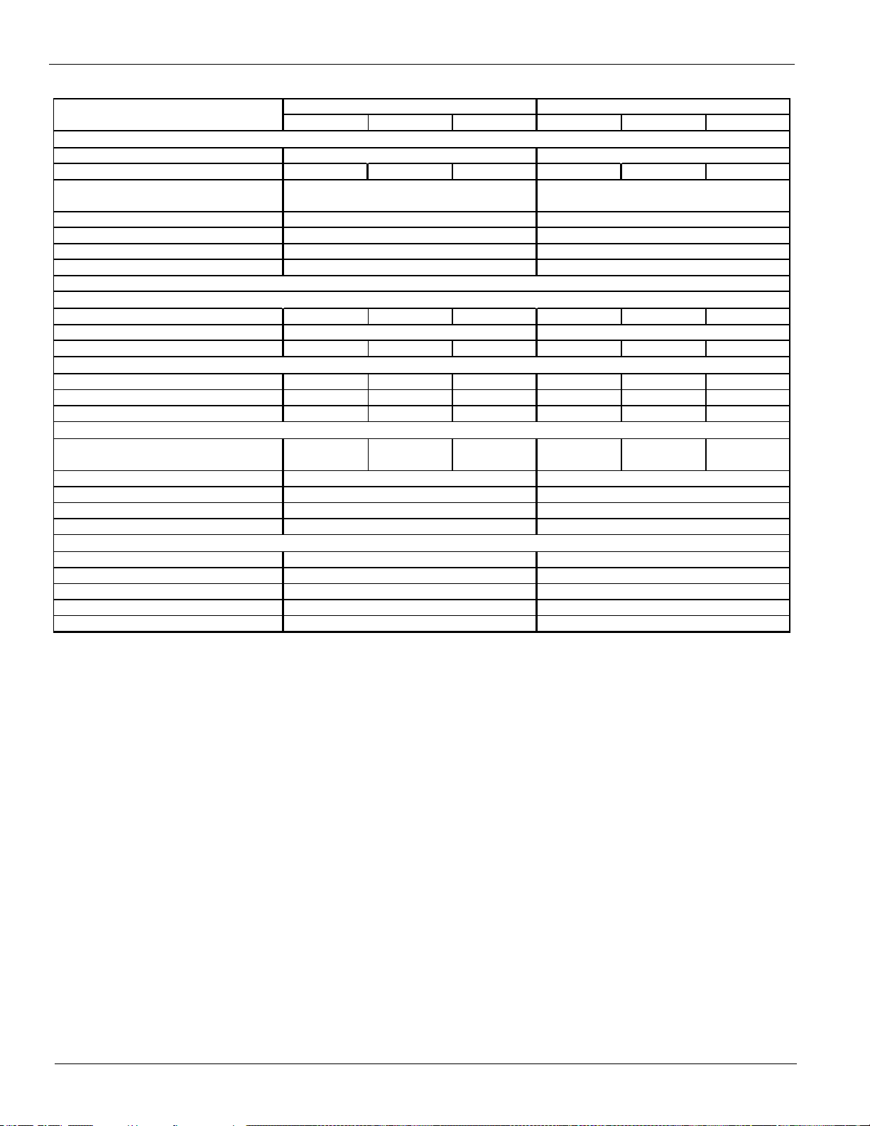
Physical Data (VFD)
Unit Cap. @ AHRI tons ( kW)
Uni t O perating Charge lbs (kg) 210 (95) 210 (95) 220 (100) 210 (95) 210 (95) 280 (187)
Unit Dimensions
L x W x H, in. (mm)
Uni t O perating Wei ght, lbs. (kg)
Uni t Shi pping Weight, lbs (kg)
Weight-Add for Copper Fins
Weight-Add for Louvered Panel s
Nominal Capacity, tons (kW) 150 (528) 150 (528) 150 (528) 150 (528) 150 (528) 175 (615)
M i nimum Capacity (% of Full Load)
Oil charge per circuit , gallons (liters) 5.5 (21) 5.5 (21) 5.5 (21) 5.5 (21) 5.5 (21) 6 (23)
Pumpdown Capacity, lbs (kg) 333 (151) 333 (151) 333 (151) 333 (151) 333 (151) 416 (189)
Coi l Inlet F ace Area, sq. ft. (sq. m.) 196.9 (18.3) 196.9 (18.3) 196.9 (18.3) 196.9 (18.3) 196.9 (18.3) 246.1 (22.8)
Rows Deep/Fins Per Inch 3 / 16 3 / 16 3 / 16 3 / 16 3 / 16 3 / 16
Number of Fans per Ci rcuit
Fan Diameter: 31.5 in. (800 mm)
Fan Motor, hp (kW)
Fan & Motor RPM
Fan Tip Speed, fpm (m /s)
Airflow, cfm (l /s)
Shell Dia.-Tube Length, in.(mm)
Water Volume, gallons (liters)
Vict au lic i nl et/out le t conn. in. ( mm)
Max. W ate r Pressu re, psi (kPa)
M ax. R efrigerant Press., psi (kPa) 325 (2241) 325 (2241)
152 (1048)
10 (273) 10 (273)
152 (1048)
6984 (35)
26 x 130 / (660 x 3300)
EVAPORATOR, DIRECT EXPANSION SHELL AND TUBE
1.4 (1.05)
850
6984 (35)
266040 (125556) 288210 (136019)
1.4 (1.05)
850
3553 (1612)
COMPRESSORS, SCREW, SE MI-HE RMETIC
1313
27152 (12316)
3870 (1755)
1460 (662) 1572 (713)
28300 (12837)
25753 (11682) 26901 (12202)
12605 x 2225 x 2548
BASIC DATA
13504 x 2225 x 2545
Data
467.7 (1644)
A
532 x 88 x 100
445.2 (1565)
496 x 88 x 100
8881088
225 (850)
CONDENSERS, V FDICIENCY FIN AND TUBE TYPE
CONDENSER FANS, DIRECT DRIVE PROPELLER TYPE
220 (831)
26 x 130 / (660 x 3300)
Note: A 20 mesh strainer must be placed in the supply water line just prior to the inlet of the evaporator.
Care must be exercised when welding pipe or flanges to the evaporator to prevent any slag from entering the vessel.
This information applies only to Rev 0B models of AWS-B. For Rev 00 models, co nsult CAT 600-6; Rev 0A, CAT 600-7.
Table 29: Physical Data (60 Hz, High Efficiency, VFD models)
WS450B T H V FD A WS475BT H VF D
CIR C U IT 1 CIRC U IT 2 CIRCU IT 3 CIRC U IT 1 CIRC U IT 2 CIRC U IT 3
34 IM 1167
Page 35

Table 30: Physical Data (60 Hz, High Efficiency, VFD models)
CIRCUIT 1 CIRCUIT 2 CIRCUIT 3 CIRCUIT 1 CIRCUIT 2 CIRCUIT 3
BASIC DATA
Uni t Cap. @ AHRI tons (kW)
Uni t O perating C harge lbs (kg)
265 (120) 265 (120) 220 (100) 265 (120) 265 (120) 280 (187)
Uni t Dimensions
L x W x H, i n. ( mm)
Uni t O perating Weight, lbs. (kg)
Uni t Ship ping Weight, lbs (kg)
Weight-Add for Copper Fins
Weight-Add for Louvered Panels
COMPRESSORS, SCREW, SE MI-HE RMETIC
Nominal Capacity, tons (kW) 175 (615) 175 (615) 150 (528) 175 (615) 175 (615) 175 (615)
Minimum Capacity (% of Full Load)
Oil charge per circuit , gallons (liters) 6 (23) 6 (23) 5.5 (21) 6 (23) 6 (23) 6 (23)
CONDENSERS, HIGH EFFICIENCY F IN AND TU BE TYP E
Pumpdown Capacity, lbs (kg) 416 (189) 416 (189) 333 (151) 416 (189) 416 (189) 416 (189)
Coi l Inlet Face Area, sq. ft. (sq. m.) 246.1 (22.8) 246.1 (22.8) 196.9 (18.3) 246.1 (22.8) 246.1 (22.8) 246.1 (22.8)
Rows Deep/Fins Per Inch 3 / 16 3 / 16 3 / 16 3 / 16 3 / 16 3 / 16
CONDENSER FANS, DIRECT DRIVE PROPELLER TYPE
Number of Fans per Circuit
Fan Diameter: 31.5 in. (800 mm)
Fan Motor, hp (kW)
Fan & Motor RPM
Fan Tip Speed, fpm (m/s)
Airflow, cfm (l/s)
EVAPORATOR, DIRECT EXPANSION SHELL AND TUBE
Shell Dia.-Tube Length, in.(mm)
Water Volume, gallons (liters)
Victaulic inlet/outlet conn. in. (mm)
Max. Water Pressure , psi (kP a)
Max. Refrigerant P ress., psi (kPa)
325 (2241) 325 (2241)
152 (1048) 152 (1048)
220 (831) 220 (831)
310380 (146482) 332550 (156945)
1.4 (1.05) 1.4 (1.05)
1684 (764) 1796 (815)
13 13
4168 (1891) 4466 (2026)
28718 (13026) 30047 (13629)
567 x 88 x 100 603 x 88 x 100
30117 (13661) 31446 (14264)
14405 x 2225 x 2548 15304 x 2225 x 2545
497.8 (1750) 524.8 (1845)
Dat a
A WS500BT H V FD A WS530BTH V FD
10 10 8 10 10 10
6984 (35) 6984 (35)
850 850
10 (273) 10 (273)
26 x 130 / (660 x 3300) 26 x 130 / (660 x 3300)
Note: A 20 mesh strainer must be placed in the supply water line just prior to the inlet of the evaporator.
Care must be exercised when welding pipe or flanges to the evaporator to prevent any slag from entering the vessel.
This information applies only to Rev 0B models of AWS-B. For Rev 00 models, co nsult CAT 600-6; Rev 0A, CAT 600-7.
Physical Data (VFD)
IM 1167 35
Page 36

Physical Data (VFD)
Unit Cap. @ AHRI tons (kW)
Unit Operating C ha rge lbs (kg) 200 (91) 200 (91) 225 (102) 225 (102) (235) (107) (235) (107)
Unit Di mensions
L x W x H , in. (mm)
Unit Operating Weight, lbs. (kg)
Unit Shipping Weight, lbs (kg)
Weight-Add for Copper Fi ns
Weight-Add for Louvered Pa nel s
Nominal Capacity, tons (kW) 105 (369) 105 (369) 105 (369) 125 (439) 125 (439) 125 (439)
Minimum Capacity (% of Ful l Load)
Oil charge per circuit , gallons (liters) 4.5 (17) 4.5 (17) 4.5 (17) 5.5 (21) 5.5 (21) 5.5 (21)
Pumpdown Capacity, lbs (kg) 333 (151) 333 (151) 375 (170) 375 (170) 375 (170) 375 (170)
Coil Inlet Face Area, sq. ft. (sq. m.) 196.9 (18.3) 196.9 (18.3) 221.5 (20.6) 221.5 (20.6) 221.5 (20.6) 221.5 (20.6)
Rows Deep/Fins Per Inch 3 / 16 3 / 16 3 / 16 3 / 16 3 / 16 3 / 16
Number of Fans per Circuit
Fan Diameter: 31.5 in. (800 m m)
Fan Motor, hp (kW)
Fan & Motor RPM
Fan Tip Speed, fpm (m/s)
Airflow, cfm (l /s)
Shell Dia.-Tube Le ngth, in.(mm)
Water Volume, gallons (liters)
Victaulic inlet/outlet conn. in. (mm)
Max. Water Pressure, psi (kPa)
Max. R e frigerant Press., psi (kPa)
325 (2241) 325 (2241)
152 (1048)
158 (599) 158 (599)
8 (2199 8 (219) 10 (273)
EVAPORATOR, DIRECT EXPANSION SHELL AND TUBE
20 x 154 / (508 x 3900) 20 x 154 / (508 x 3900) 26 x 154 / (660 x 3900)
CONDENSER FANS, DIRECT DRIVE PROPELLER TYPE
9
20 20 20
CONDENSERS, HIGH EFFICIENCY FIN AND TUBE TYPE
1124 (510) 1124 (510)
17183 (7794) 18389 (8341)
2372 (1076) 2679 (1215) 2679 (1215)
8602 x 2225 x 2548 9504 x 2225 x 2545 9504 x 2225 x 2545
232.7 (818) 256.3 (901) 277.6 (976)
A
18435 (8362) 19641 (8909) 21512 (9758)
374 x 88 x 100
19859 (9008)
8899
COMPRESSORS, SCREW, SE MI-HERMETIC
1012 (459)
Dat a
BASIC DATA
339 x 88 x 100 374 x 88 x 100
9
1.4 (1.05) 1.4 (1.05) 1.4 (1.05)
6984 (35) 6984 (35) 6984 (35)
850 850 850
152 (1048) 152 (1048)
325 (2241)
177360 (83704) 199530 (94167) 199530 (94167)
276 (1043)
Note: A 20 mesh strainer must be placed in the supply water line just prior to the inlet of the evaporator.
Care must be exercised when welding pipe or flanges to the evaporator to prevent any slag from entering the vessel.
This information applies only to Rev 0B models of AWS-B. For Rev 00 models, consult CAT 600-6; Rev 0A, CAT 600- 7.
Table 31: Physical Data (60 Hz, Premium Efficiency, VFD models)
AWS240BDP VFD
CIRCUIT 1 CIRCUIT 2 CIRCUIT 1 CIRCUIT 2 CIRCUIT 1 CIRCUIT 2
WS265B DP V FD AWS290B DP VFD
36 IM 1167
Page 37

Table 32: Physical Data (60 Hz, Premium Efficiency, VFD models)
U n it Cap. @ AHRI tons (kW)
Unit Operating Charge lbs (kg) 250 (113) 250 (113) 260 (118) 260 (118) 260 (118) 300 (136)
Unit Dimensions
L x W x H , in. (mm)
Unit Operating Weight, lbs. (kg)
Unit Shipping Weight, lbs (kg)
Weight-Add for Copper Fins
Weight-Add for Louvered Panels
Nominal Capacity, tons (kW) 125 (439) 150 (528) 150 (528) 150 (528) 150 (528) 175 (615)
Minimum Capacity (% of Full Load)
Oil charge per circuit , gallons (liters) 5.5 (21) 5.5 (21) 5.5 (21) 5.5 (21) 5.5 (21) 6 (23)
Pumpdown Capacity, lbs (kg) 416 (189) 416 (189) 416 (189) 416 (189) 416 (189) 500 (227)
Coil Inlet Face Area, sq. ft. (sq. m.) 246.1 (22.8) 246.1 (22.8) 246.1 (22.8) 246.1 (22.8) 246.1 (22.8) 295.3 (27.4)
R o ws Dee p/Fins Per I n ch 3 / 16 3 / 16 3 / 16 3 / 16 3 / 16 3 / 16
Number of Fans per Circuit
Fan Diameter: 31.5 in. (800 mm)
Fa n Motor, hp (kW)
Fan & Motor RPM
Fan Tip Spe ed, fpm (m/s)
Ai r flow, cfm (l/ s )
Shell Dia.-Tu be Len gth, in.(mm)
Water Volume, gallons (liters)
Victaulic inlet/outlet conn. in. (mm)
Max. W ater Pressure, psi (kPa)
Max. Refrigerant Press., psi (kPa)
276 (1043)
325 (2241)
152 (1048)
26 x 154 / (660 x 3900) 26 x 154 / (660 x 3900)
10 (273) 10 (273)10 (273)
221700 (104630) 243870 (115093)
EVAPORATOR, DIRECT EXPANSION SHELL AND T UBE
259 (979) 259 (979)
26 x 154 / (660 x 3900)
CONDENSER FANS, DIRECT DRIVE PROPELLER TYPE
6984 (35) 6984 (35)
10 10
1.4 (1.05)
10 12
20
CONDENSERS, VFDICIENCY FIN AND TUBE TYPE
1236 (561) 1236 (561) 1348 (611)
20 20
11701 x 2225 x 2548
20832 (9449) 22788 (10337)
2968 (1346) 3256 (1477)
10402 x 2225 x 2545 10402 x 2225 x 2545
303.8 (1068) 324.7 (1142) 354.8 (1247)
461 x 88 x 100
Dat a
22485 (10199)
410 x 88 x 100 410 x 88 x 100
2968 (1346)
20832 (9449)
COMPRESSOR S, SCREW, SE MI-HE RMETIC
22485 (10199)
BASIC DATA
A
24441 (11086)
10 10
850 850
1.4 (1.05)1.4 (1.05)
221700 (104630)
6984 (35)
850
152 (1048) 152 (1048)
325 (2241) 325 (2241)
Note: A 20 mesh strainer must be placed in the supply water line just prior to the inlet of the evaporator.
Care must be exercised when welding pipe or flanges to the evaporator to prevent any slag from entering the vessel.
This information applies only to Rev 0B models of AWS-B. For Rev 00 models, consult CAT 600-6; Rev 0A, CAT 600-7.
Physical Data (VFD)
AWS310BDP VFD
WS330B DP VFD A WS 365BDP V FD
CIRCUIT 1 CIRCUIT 2 CIRCUIT 1 CIRCUIT 2 CIRCUIT 1 CIRCUIT 2
IM 1167 37
Page 38

Physical Data (VFD)
CIRCUIT 1 CIRCUIT 2
BASIC DATA
U n it Cap. @ AHRI tons (kW)
Unit Operating Charge lbs (kg)
310 (141) 310 (141)
Unit Dimensions
L x W x H, in. (mm)
Unit Operating Weight, lbs. (kg)
Unit Shipping Weight, lbs (kg)
Weight-Add for Copper Fins
Weight-Add for Louvered Panel s
COMPRESSORS, SCREW, SEMI-HERMETIC
Nominal Capacity, tons (kW)
175 (615) 175 (615)
Minimum Capacity (% of Full Load)
Oil charge per circuit , gallons (liters)
6 (23) 6 (23)
CONDENSERS, HIGH EFFICIENCY FIN AND TUBE TYPE
Pumpdown Capacity, lbs (kg)
500 (227) 500 (227)
C o il Inl e t Face Area, sq. ft. (sq. m.)
295.3 (27.4) 295.3 (27.4)
Rows Deep/Fins Per Inch
3 / 16 3 / 16
CONDENSER FANS, DIRECT DRIVE PROPELLER TYPE
Number of Fans per Circuit
Fan Diameter: 31.5 in. (800 mm)
Fan Motor, hp (kW)
Fan & Motor RPM
Fan Tip Speed, fpm (m/s)
Airflow, cfm (l/s)
EVAPORATOR, DIRECT EXPANSION SHELL AND TUBE
Shell Dia.-T ube Length, i n.(mm)
Water Volume, gallons (liters)
Victaulic inlet/outlet conn. in. (mm)
Ma x. Water Pressure, psi (kPa)
Max. Refrigerant Press., psi (kPa)
325 (2241)
10 (273)
152 (1048)
26 x 154 / ( 660 x 3900)
12 12
1460 (662)
20
3553 (1612)
12604 x 2225 x 2545
AWS400BDP VFD
Data
385.4 ( 1355)
496 x 88 x 100
24228 (10990)
25881 (11740)
850
1.4 ( 1. 05)
266040 (125556)
6984 (35)
259 (979)
Note: A 20 mesh strainer must be placed in the supply water line just prior to the inlet of the evaporator.
Care must be exercised when welding pipe or flanges to the evaporator to prevent any slag from entering the vessel.
This information applies only to Rev 0B models of AWS-B. For Rev 00 models, co nsult CAT 600-6; Rev 0A, CAT 600-7.
Table 33: Physical Data (60 Hz, Premium Efficiency, VFD models)
38 IM 1167
Page 39

Lifting & Mounting Weights (I-P Units)
L1 L2 L3 L4 L5 L6 L7 L8 M1 M2 M3 M4 M5 M6 M7 M8 M9 M10 M11 M12
--
--
--
--
--
--
--
--
--
--
--
--
--
--
--
--
--
--
-
-
-
-
-
-
-
-
-
-
-
-
-
-
-
-
3769
MOUNTING LOADS FOR EACH POINT (L BS)
-
-
-
-
-
---
3735 2918 15952892 2264 2243 16093364 3333 2988 2961 4096 4059
2208 1793 1745
AWS500BTH
28 3886 3850 3716 3683
3653 3457 3364 2685 2612 22703469 3166 3081 2760 2686 3754
AWS475BTH
26 3758 3656 3566
2490 2468 1997 1979 1431 14182440 2417 3762 3727 3408 3377
925
AWS450BTH
24 3653 3620 3405 3374 2888 2862
3150 2141 2131 1556 1549 9292596 1961 1952 3564 3548 3165
--
AWS410BDH
24 3314 3299 3037 3023 2608
3263 3249 2394 2384 1701 16942414 2403 1897 1888 3598 3581
1317 - -
AWS390BDH
22 3275 3260 2937 2924
3462 3080 3080 2363 2363 13173014 1950 1950 1230 1230 3462
AWS350BDH
20 3594 3594 3014
2337 2253 1369 1320 - -1272 1226 3355 3235 3001 2893
-
AWS330BDH
20 3473 3349 2934 2828 1942 1873
2711 1786 1786 1028 1028 -1701 1075 1075 3206 3206 2711
--
AWS300BDH
16 3065 3065 2455 2455 1701
2711 2711 1786 1786 1028 10281701 1701 1075 1075 3206 3206
808 - -
AWS280BDH
16 3065 3065 2455 2455
3160 2554 2542 1391 1385 8113485 - - - - 3175
AWS250BDH
14 4158 4139 3501
1380 1301 821 774 - -- - 3103 2924 2503 2359
-
AWS230BDH
14 4052 3818 3476 3276 - -
2373 1722 1714 - - -- - - 2737 2724 2383
AWS210BDH
12 3892 3875 2678 2665 -
15723202 3116 4317 4200 15304005 3896 3194 3108 2426 2360
1433
AWS530BTH
30 4071 3961 3921 3815 3610 3512
3845 3069 3041 2300 2279 14463 413 2985 2958 4193 4155 3881
1517 1503
AWS550BTS
30 3963 3927 3794 3760 3444
3782 3748 2889 2863 2203 21833305 3275 2859 2833 4125 4088
2118 1529 1516
AWS525BTS
28 3925 3890 3724 3690
3994 3651 3618 2666 2642 21373695 3097 3069 2455 2432 4030
2079 2060 1488 1474
AWS500BTS
26 4032 3995 3728
3921 3885 3552 3520 2594 2570
1182
24 3816 3782 3556 3524 3014 2987 2544 2521
3635 2473 2496 1867 1884 11712 828 2131 2151 4036 4073 3602
--
AWS450BTS
24 3945 3982 3574 3607 2802
3500 3468 2880 2854 2403 238226 18 2594 1994 1976 3738 3705
2318 - -
AWS425BTS
22 3795 3760 3413 3382
3668 3380 3427 2762 2800 22863334 2506 2541 1893 1919 3618
1166 1166 - -
AWS400BTS
22 3664 3715 3288
3434 3434 3030 3030 2272 2272
-
20 3567 3567 2960 2960 1847 1847 1094 1094
3030 2272 2272 1166 1166 -1847 1094 1094 3434 3434 3030
--
AWS350BDS
20 3567 3567 2960 2960 1847
2950 2936 1769 1761 803 7991679 1672 862 858 3580 3563
807 - -
AWS310BDS
16 3461 3446 2664 2652
3333 2862 2760 1749 1686 837
-
3330 3211 2583 2490 1659 1599 892 860 3457
3175 2519 2508 1264 1258 6383118 - - - - 3190
AWS260BDS
14 4207 4188 3132
1264 1258 638 635 - -- - 3190 3175 2519 250814 4207 -4188 3132 3118 -
- - 1498 - -3121 3106 2558 2547 15054364 4345 2547 2536 - -
2498 2387 1548 1479 - -- - - - 3005 287112 4214 4026 2560 2445
1422 1415 - - - -- - 2805 2792 2324 2313
LIFTING W EIGHT F OR EACH P OINT (LB S)
AWS190BDS
10 3921 3903 2358 2347 - -
AWS470BTS
AWS250BDS
# OF FANS
AWS225BDS
12
16
AWS210BDS
U NIT SIZE
AWS290BDS
AWS375BDS
--
635 -
Lifting & Mounting Weights (I-P Units)
Note: Lifting and Mounting Locations begin on page 43. See Physical Data tables, beginning on page 43 for Shipping and
Operating weights, and weight adjustments for accessories and options. All drawings and weights in this manual are
applicable to AWS B-vintage (Rev 0B) models only. For drawings and information related to (Rev 00) models, consult CAT
600-6. To determine if your unit is Rev 00 or Rev 0A, check Item 62 of the Item Summary Report for your unit. If you have
additional questions, contact your Daikin McQuay representative.
Table 34: Lifting & Mounting Weights (IP units)
IM 1167 39
Page 40

Lifting & Mounting Weights (I-P Units)
L1 L2 L3 L4 L5 L6 L7 L8 M1 M2 M3 M4 M5 M6 M7 M8 M9 M10 M11 M12
AWS 170BDS VFD 10
2814 2821 2265 2272 1471 1475 - - 2217 2223 1898 1904 1512 1516 1194 1197 - - - -
AWS 190BDS VFD 12
3139 3040 2530 2450 1647 1595 - - 2464 2387 2112 2045 1684 1631 1332 1290 - - - -
AWS 200BDS VFD 12
3146 3146 2501 2501 1567 1567 - - 2474 2474 2099 2099 1644 1644 1270 1270 - - - -
AWS 210BDH VFD 12
2732 2738 2323 2328 1731 1735 - - 2135 2140 1904 1908 1624 1628 1394 1397 - - - -
AWS 230BDH VFD 14
2698 2566 2560 2434 2358 2243 - - 2410 2292 2015 1916 1536 1461 1142 1086 - - - -
AWS 250BDH VFD 14
2758 2758 2593 2593 2354 2354 - - 2452 2452 2045 2045 1551 1551 1145 1145 - - - -
AWS 280BDH VFD 16
3103 3110 2531 2537 1702 1706 - - 2468 2473 2153 2158 1771 1775 1457 1461 - - - -
AWS 300BDH VFD 16
3103 3110 2531 2537 1702 1706 - - 2468 2473 2153 2158 1771 1775 1457 1461 - - - -
AWS 330BDH VFD 20
3490 3391 2987 2902 1937 1882 1271 1235 2530 2458 2323 2257 2073 2014 1867 1814 1330 1292 - -
AWS 350BDH VFD 20
3610 3627 3073 3087 1950 1959 1238 1243 2619 2631 2391 2402 2114 2124 1886 1895 1293 1299 - -
AWS 390BDH VFD 22
3589 3598 3084 3093 2469 2475 1860 1865 2418 2424 2380 2387 2331 2337 2204 2210 2102 2108 - -
AWS 410BDH VFD 24
3619 3631 3197 3207 2682 2690 1903 1909 2509 2517 2385 2393 2225 2232 1813 1818 1577 1582 1325 1329
AWS 450BTH VFD 24
4013 4022 3599 3607 2920 2927 2331 2336 2645 2651 2556 2562 2441 2447 2142 2147 1980 1985 1796 1800
AWS 475BTH VFD 26
4148 4079 3767 3704 3142 3090 2507 2465 2658 2613 2593 2550 2510 2467 2292 2254 2176 2139 2042 2007
AWS 500BTH VFD 28
4180 4197 3882 3898 3394 3408 2874 2885 2869 2880 2791 2802 2690 2701 2428 2438 2226 2235 2025 2033
AWS 530BTH VFD 30
4380 4323 4096 4042 3629 3581 3018 2979 3084 3043 2995 2956 2880 2843 2582 2548 2300 2270 1986 1960
AWS 240BDP VFD 16
2734 2740 2325 2330 1733 1737 1286 1289 2215 2220 2001 2006 1742 1746 1529 1532 1217 1220 - -
AWS 265BDP VFD 18
2878 2800 2514 2446 1987 1934 1452 1413 2327 2264 2141 2083 1915 1864 1730 1683 1352 1316 - -
AWS 290BDP VFD 18
3036 3036 2675 2675 2151 2151 1618 1618 2488 2488 2305 2305 2083 2083 1901 1901 1529 1529 - -
AWS 310BDP VFD 20
3302 3302 2918 2918 2115 2115 1606 1606 2449 2449 2328 2328 2182 2182 2061 2061 1747 1747 - -
AWS 330BDP VFD 20
3302 3302 2918 2918 2115 2115 1606 1606 2449 2449 2328 2328 2182 2182 2061 2061 1747 1747 - -
AWS 365BDP VFD 22
3496 3422 3125 3058 2672 2615 2224 2177 2441 2389 2449 2397 2460 2408 2489 2436 2512 2459 - -
AWS 400BDP VFD 24
3712 3723 3335 3344 2874 2881 2177 2183 2653 2660 2538 2545 2388 2395 2005 2011 1787 1792 1552 1557
--
--
--
--
--
--
--
MOUNTING LOADS FOR EACH POI NT (LBS)
1282 - -1849 1287
1148 11433426 3410 2382 2371 1786 17782830 2818 2265 2255 3833 3815
2117 - -
AWS 400B D P
24 3446 3431 3205 3190
3566 3418 3311 2733 2647 21862889 2662 2578 2345 2271 3682
1839 1839
AWS 365B D P
22 3190 3089 2982
3321 3321 3057 3057 2562 2562
--
AWS 330B D P
20 3299 2137 2137 1628 1628
3057 3057 2562 2562 1839 18392137 2137 1628 1628 3321 3321
1622 - -
AWS 310B D P
20 3299 3299 2889 2889
23633361 3014 16223014 2363
1428
5183
3009 2784 2684
33611654 165421833041
AWS 290B D P
18 3041
2151
AWS 265B D P
276718 2870
3299 2889 2889
AWS 240B D P
16 2699
2486 2397
2686 2258 1736 1294 1288
UNIT SIZE # OF FANS
LIF TING WEIGHT FO R E A C H PO INT (LBS )
2926 2912 2554 2542
3121 -
1857
14302074
1728
2011 1939 1481
2657 2657
2268
1379 -
Table 35: Lifting & Mounting Weights (IP units) continued
40 IM 1167
Page 41

Lifting & Mounting Weights (SI Units)
L1 L2 L3 L4 L5 L6 L7 L8 M1 M2 M3 M4 M5 M6 M7 M8 M9 M10
U nit S ize
Hz
# OF
FANS
LIFTING WEIGHT FOR EACH POINT (KG) MOUNTING LOADS FOR EACH POINT (KG)
AWS190BDS
60 10 1779 1770 1070 1065 - - - -1054 1049 645 642
AWS210BDS
60 12 1912
--- - 1272 1266
---13631826 1161 1109 - 671 - - -1302 1133 1083 702 -
AWS225BDS
60
14 1908
12 1980
1900 1421 1414 - 573---1447 -
AWS250BDS
60 571 289 288 -1440 1143 1138
1900 1421 1414 -
AWS260BDS
60 14 1908 288 -1440 1143 1138 573
1171 1129 752 725
571 289---1447
405 390 1568 1512
-
AWS290BDS
60 16 1511 1456 380 366 - -1298 1252 793 765
1563 1209 1203 762
AWS310BDS
60 16 1570 362 -1616 1338 1332 802
1343 1343 838 838
799 364758 391 389 1624
496 496 1558 1558
-
AWS350BDS
60 20 1618 1618 529 529 - -1374 1374 1030 1030
1618 1343 1343 838
AWS375BDS
60 20 1618 529 -1558 1374 1374 1030
1491 1512 1137 1153
1030 529838 496 496 1558
859 870 1641 1664
-
AWS4 00B TS
60 22 1662 1685 1037 1051 - -1533 1554 1253 1270
1706 1548 1534 1188
AWS4 25B TS
60 22 1721 1080 -1681 1588 1573 1306
1621 1636 1271 1283
1295 10901177 904 896 1696
967 976 1831 1847
-
AWS4 50B TS
60 24 1789 1806 847 855 531 5361634 1649 1122 1132
1715 1613 1598 1367
AWS4 70B TS
60 24 1731 934 6751762 1611 1597 1177
1691 1676 1405 1392
1166 9431355 1154 1144 1779
1114 1103 1828 1812
669
AWS5 00B TS
60 26 1829 1812 969 961 694 6881656 1641 1209 1198
1764 1689 1674 1499
AWS5 25B TS
60 28 1780 990 6881854 1715 1700 1310
1721 1706 1562 1548
1299 9991486 1297 1285 1871
1354 1342 1902 1885
682
AWS5 50B TS
60 30 1798 1781 1043 1034 656 6501760 1744 1392 1379
1758 1215 1209 -
AWS210BDH
60 12 1766 --1236 1081 1076 781 778 ----1241 -
AWS230BDH
60 14 1838 - - - 14071732 1577 1486 - 590 372 351 -1326 1135 1070 626 -
AWS250BDH
60 14 1886 1877 1588 1581 - - - -1158 1153 631 628
AWS280BDH
60 16 1390
368 367- - 1440 1433
772 488 488 14541390 1114 1114 772 810 466 466 -1454 1230 1230 810 -
AWS300BDH
60 16 1390 1390 1114 1114 772 772 - -1230 1230 810 810
AWS330BDH
60 20 1575
466 466488 488 1454 1454
849 577 556 15221519 1331 1283 881 599 -1467 1361 1312 1060 -
AWS350BDH
60 20 1630 1630 1367 1367
1022 621
--1397 1397 1072 1072
AWS390BDH
60 22 1485
597 5971571 1571
1090 860 856 16321479 1332 1326 1095 1081 772 768 -1624 1480 1474 1086 -
AWS410BDH
60 24 1503 1496 1378 1371 1183 1178 - -1436 1429 971 967
AWS4 50B TH
60 24 1657
706 703889 885 1617 1609
1298 11071642 1544 1530 1310
1574 1436 1398
1119 906 8981691 1546 1532 1129
AWS4 75B TH
60 26 1705 1658 1618 1218 1703 1657
6436491096 1706
1568 1526 1218
AWS5 00B TH
60 28 1763 18581746 1686 1671 1526 1841 1710 16941355 1343
7921185 1030 1002 813
723
1727 1448 1384 1100 1070 713
1324 1312 1027
180814131637 1593 1452
730
1946 1859
10171512
694
1971 1155 1150 -
1797
1160 1155 683---1416 -680---1409
1847 1779
558 558885 885
1730
AWS5 30B TH
60 30
1252
Table 36: Lifting & Mounting Weights (SI units)
Lifting & Mounting Weights (SI Units)
IM 1167 41
Page 42

Lifting & Mounting Weights (SI Units)
L1 L2 L3 L4 L5 L6 L7 L8 M1 M2 M3 M4 M5 M6 M7 M8 M9 M10 M11 M12
AWS170BD S VFD
60 10
1276 1280 1027 1031 667 669
--
1006 1008 861 864 686 688 542 543
----
AWS190BD S VFD
60 12
1424 1379 1148 1111 747 723
--
1118 1083 958 928 764 740 604 585
----
AWS200BD S VFD
60 12
1427 1427 1134 1134 711 711 --1122 1122 952 952 746 746 576 576 ----
AWS210BDH V FD
60 12 1239 1242 1054 1056 785 787 - - 968 971 864 865 737 738 632 634 - - - -
AWS230BDH V FD
60 14 1224 1164 1161 1104 1070 1017 - - 1093 1040 914 869 697 663 518 493 - - - -
AWS250BDH V FD
60 14 1251 1251 1176 1176 1068 1068 - - 1112 1112 928 928 704 704 519 519 - - - -
AWS280BDH V FD
60 16 1408 1411 1148 1151 772 774 - - 1119 1122 977 979 803 805 661 663 - - - -
AWS300BDH V FD
60 16 1408 1411 1148 1151 772 774 - - 1119 1122 977 979 803 805 661 663 - - - -
AWS330BDH V FD
60 20 1583 1538 1355 1316 879 854 577 560 1148 1115 1054 1024 940 914 847 823 603 586 - -
AWS350BDH V FD
60 20 1637 1645 1394 1400 885 889 562 564 1188 1193 1085 1090 959 963 855 860 587 589 - -
AWS390BDH V FD
60 22 1628 1632 1399 1403 1120 1123 844 846 1097 1100 1080 1083 1057 1060 1000 1002 953 956 - -
AWS410BDH V FD
60 24 1642 1647 1450 1455 1216 1220 863 866 1138 1142 1082 1085 1009 1012 822 825 715 718 601 603
AWS450B TH VFD
60 24 1820 1824 1632 1636 1325 1328 1057 1060 1200 1203 1160 1162 1107 1110 971 974 898 900 814 816
AWS475B TH VFD
60 26 1882 1850 1709 1680 1425 1401 1137 1118 1205 1185 1176 1156 1138 1119 1040 1022 987 970 926 911
AWS500B TH VFD
60 28 1896 1904 1761 1768 1540 1546 1303 1309 1301 1307 1266 1271 1220 1225 1101 1106 1010 1014 918 922
AWS530B TH VFD
60 30 1987 1961 1858 1833 1646 1624 1369 1351 1399 1380 1359 1341 1307 1289 1171 1156 1043 1029 901 889
AWS240BDP VFD
60 16 1240 1243 1055 1057 786 788 583 585 1005 1007 908 910 790 792 694 695 552 553 - -
AWS265BDP VFD
60 18 1305 1270 1140 1110 901 877 659 641 1056 1027 971 945 869 846 785 763 613 597 - -
AWS290BDP VFD
60 18 1377 1377 1213 1213 976 976 734 734 1129 1129 1046 1046 945 945 862 862 694 694 - -
AWS310BDP VFD
60 20 1498 1498 1324 1324 959 959 728 728 1111 1111 1056 1056 990 990 935 935 792 792 - -
AWS330BDP VFD
60 20 1498 1498 1324 1324 959 959 728 728 1111 1111 1056 1056 990 990 935 935 792 792 - -
AWS365BDP VFD
60 22 1586 1552 1417 1387 1212 1186 1009 987 1107 1084 1111 1087 1116 1092 1129 1105 1140 1115 - -
AWS400BDP VFD
60 24 1684 1689 1513 1517 1303 1307 987 990 1203 1207 1151 1154 1083 1086 910 912 810 813 704 706
1128 1087 912 880 672 648 1416 1365
AWS 265B D P
60 18 1302 1255 649 626 - -1263 1217 976 941
1379 1205 1205 2351
AWS 290B D P
60 18 1379 736 -1525 1367 1367 1072
1310 1310 969 969
1072 736990 750 750 1525
738 738 1506 1506
-
AWS 310B D P
60 20 1496 1496 834 834 - -1387 1387 1162 1162
1496 1310 1310 969
AWS 330B D P
60 20 1496 834 -1506 1387 1387 1162
1353 1310 1207 1169
1162 834969 738 738 1506
1064 1030 1670 1617
-
AWS 365B D P
60 22 1447 1401 992 960 - -1550 1502 1240 1201
1556 1454 1447 1284
AWS 400B D P
60 24 1563 1547 10801278 1027 1023 1739 -1075 810 806 -1730 1554
-1321 1158
AWS 240B D P
60 16 1224 587 584 1153 84313271219 1029 7841024 787
Unit S ize Hz
# OF
FANS
LIF T ING WEIGHT FOR EACH PO INT (KG)
-
--
--
-839 584 581
--
MOUNTING LOADS FOR EACH POINT ( KG)
--
--
--
-
Table 37: Lifting & Mounting Weights - (SI units) continued
42 IM 1167
Page 43
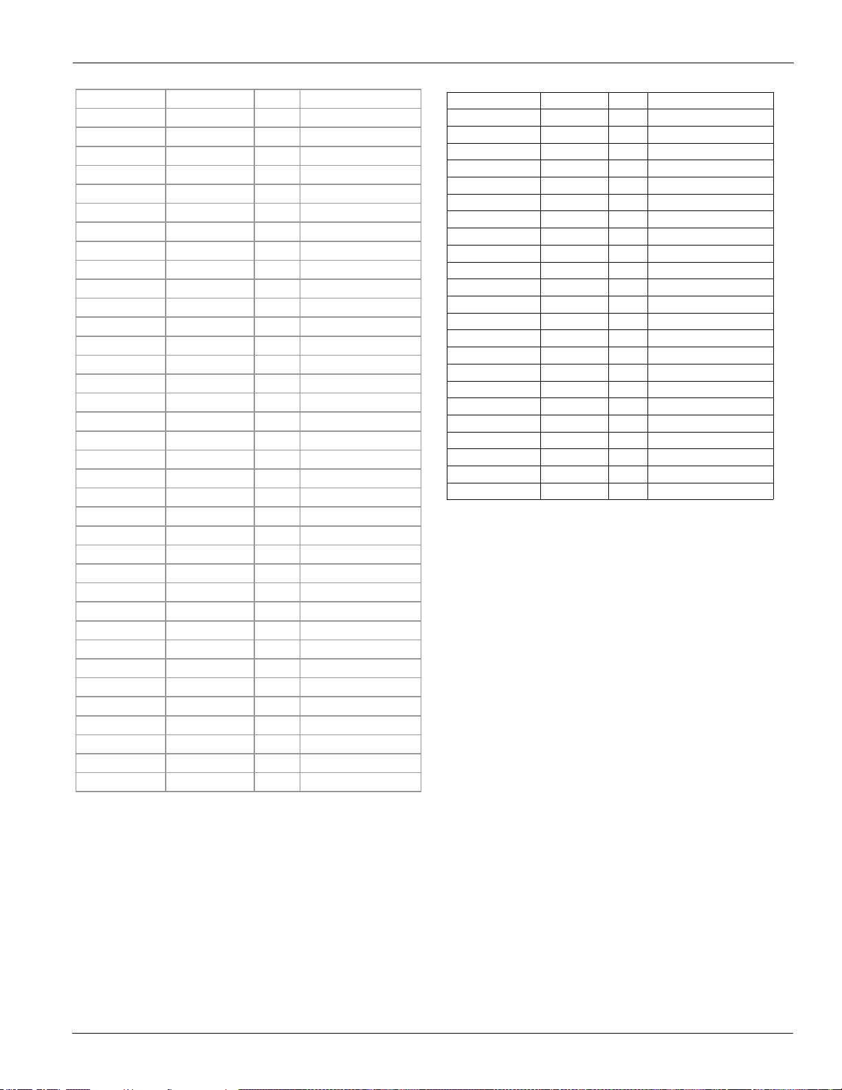
Index of Lifting & Mounting Drawings
Table 38: Dimension Drawing In de x (no n-V FD mode ls )
Model Efficiency Fans Figure & Page
AWS190BDS Standard 10 page 44
AWS210BDS Standard 12 page 44
AWS210BDH High 12 page 44
AWS225BDS Standard 12 page 44
AWS230BDH High 14 page 45
AWS240BDP Premium 16 page 45
AWS250BDS Standard 14 page 45
AWS250BDH High 14 page 45
AWS260BDS Standard 14 page 45
AWS265BDP Premium 18 page 46
AWS280BDH High 16 page 45
AWS290BDS Standard 16 page 45
AWS290BDP Premium 18 page 46
AWS300BDH High 16 page 45
AWS310BDS Standard 16 page 45
AWS310BDP Premium 20 page 46
AWS330BDH High 20 page 46
AWS330BDP Premium 20 page 46
AWS350BDS Standard 20 page 46
AWS350BDH High 20 page 46
AWS365BDP Premium 22 page 47
AWS375BDS Standard 20 page 46
AWS390BDH High 22 page 47
AWS400BTS Standard 22 page 47
AWS400BDP Premium 24 page 48
AWS410BDH High 24 page 48
AWS425BTS Standard 22 Figure 21, page 47
AWS450BTS Standard 24 Figure 23, page 48
AWS450BTH High 24 Figure 23, page 48
AWS470BTS Standard 24 Figure 23, page 48
AWS475BTH High 26 Figure 24, page 49
AWS500BTS Standard 26 Figure 24, page 49
AWS500BTH High 28 Figure 25, page 49
AWS525BTS Standard 28 Figure 25, page 49
AWS530BTH High 30 Figure 26, page 49
AWS550BTS Standard 30 Figure 26, page 49
Index of Lifting & Mounting Drawings
Table 39: Dimen si on Drawing Index (VFD models)
Model Efficiency Fans Figure & Page
AWS170BDS Standard 10 Figure 27, page 50
AWS190BDS Standard 12 Figure 28, page 50
AWS200BDS Standard 12 Figure 28, page 50
AWS210BDH High 12 Figure 28, page 50
AWS230BDH High 14 Figure 29, page 51
AWS240BDP Premium 16 Figure 30, page 51
AWS250BDH High 14 Figure 29, page 51
AWS265BDP Premium 18 Figure 31, page 52
AWS280BDH High 16 Figure 30, page 51
AWS290BDP Premium 18 Figure 31, page 52
AWS300BDH High 16 Figure 30, page 51
AWS310BDP Premium 20 Figure 32, page 52
AWS330BDH High 20 Figure 32, page 52
AWS330BDP Premium 20 Figure 32, page 52
AWS350BDH High 20 Figure 32, page 52
AWS365BDP Premium 22 Figure 33, page 52
AWS390BDH High 22 Figure 33, page 52
AWS400BDP Premium 24 Figure 34, page 53
AWS410BDH High 24 Figure 34, page 53
AWS450BTH High 24 Figure 35, page 53
AWS475BTH High 26 Figure 36, page 53
AWS500BTH High 28 Figure 37, page 54
AWS530BTH High 30 Figure 38, page 54
IM 1167 43
Page 44
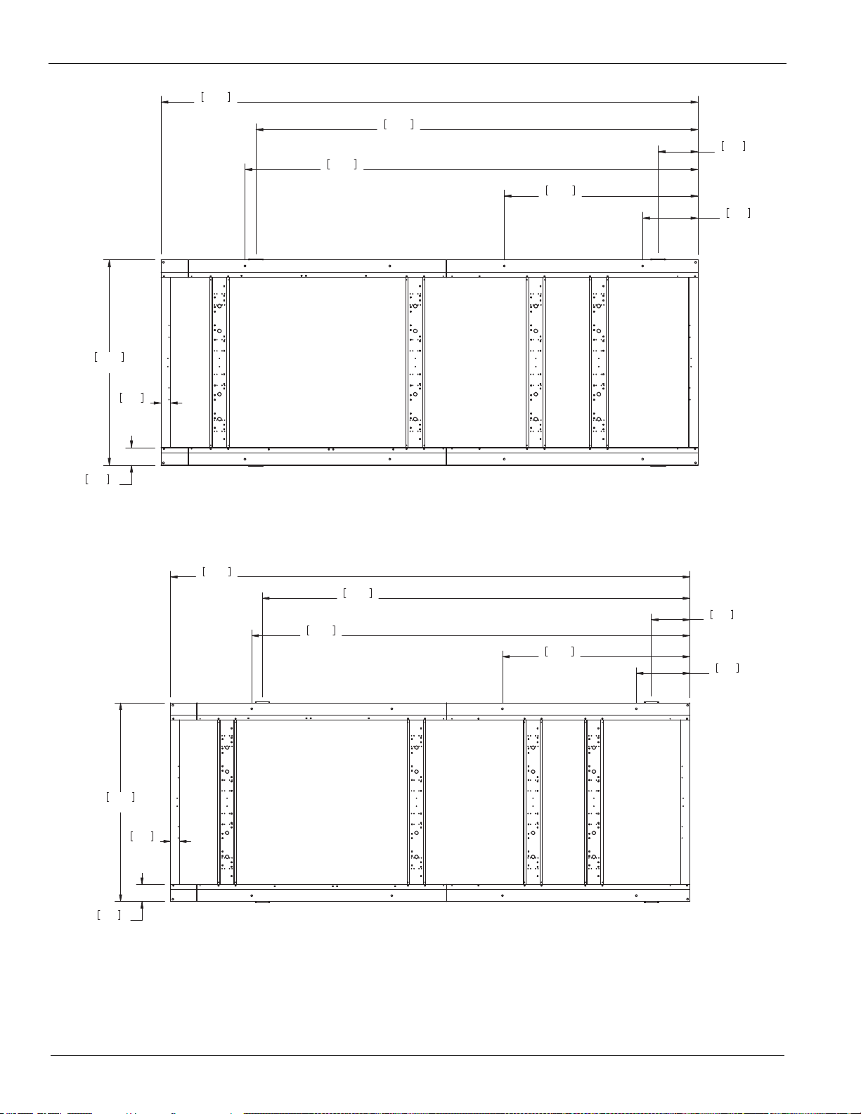
Lifting & Mounting Dimensions (non-VFD)
229.1
5820
23.6
600
82.7
2100
87.6
2225
193.3
4910
7.5
190
3.9
100
17.0
431
188.6
4791
CONTROL BOX
L1
M1M3
L3
M5
L2
M2M4
L4
M6
AWS 10 FAN DIM. DWG
331426601C020A
229.1
5820
23.6
600
82.7
2100
87.6
2225
193.3
4910
7.5
190
3.9
100
17.0
431
188.6
4791
CONTROL BOX
L1
M1M3
L3
M5
L2
M2M4
L4
M6
AWS 12 FAN DIM. DWG
*3314266020A1*
Lifting & Mounting Dimensions (non-VFD)
Figure 14: AWS190BDS (non-VFD)
Figure 15: AWS210BDS/H, AWS225BDS (non-VFD)
44 IM 1167
Page 45

Lifting & Mounting Dimensions (non-VFD)
264.6
6720
23.6
600
82.7
2100
248.4
6310
87.6
2225
2.6
66
193.3
4910
7.5
190
3.9
100
17.0
431
188.6
4791
CONTROL BOX
L1
M1M3
L3
M5M7
L2
M2M4
L4
M6M8
AWS 14 FAN DIM. DWG
331426603C020A
300.0
7620
23.6
600
82.7
2100
283.9
7210
87.6
2225
2.6
66
193.3
4910
7.5
190
3.9
100
17.0
431
93.7
2381
188.6
4791
267.4
6791
CONTROL BOX
L1
M1M3
L3L5
M5M7
L7
L2
M2M4
L4L6
M6M8
L8
AWS 16 FAN DIM. DWG
331426604C020A
Figure 16: AWS230BDH, AWS250BDS/H, AWS260BDS (non-VFD)
Figure 17: AWS240BDP, AWS280BDH, AWS290BDS, AWS300BDH, AWS310BDS (non-VFD)
IM 1167 45
Page 46

Lifting & Mounting Dimensions (non-VFD)
335.5
8520
23.6
600
82.7
2100
319.3
8110
87.6
2225
2.6
66
193.3
4910
7.5
190
3.9
100
17.0
431
93.7
2381
188.6
4791
294.6
7484
CONTROL BOX
L1
M1M3
L3L5
M5M7
L7
L2
M2M4
L4L6
M6
M8
L8
AWS 18 FAN DIM. DWG
331426605C020A
370.9
9421
23.6
600
82.7
2100
354.7
9010
87.6
2225
2.6
66
193.3
4910
7.5
190
3.9
100
17.0
431
93.7
2381
234.7
5961
330.1
8384
CONTROL BOX
L1
M1M3
L3L5
M5M7
L7
L2
M2M4
L4L6
M6M8
L8
AWS 20 FAN DIM. DWG
331426606C020A
Figure 18: AWS265BDP, AWS290BDP (non-VFD)
Figure 19: AWS310BDP, AWS330BDH/P, AWS350BDS/H, AWS375BDS (non-VFD)
46 IM 1167
Page 47

Figure 20: AWS365BDP, AWS390BDH (non-VFD)
422.0
10720
23.6
600
82.7
2100
236.2
6000
358.7
9110
87.6
2225
2.6
66
7.5
190
3.9
100
17.0
431
93.7
2381
212.6
5401
330.1
8384
CONTROL BOX
L1
M1M3
L3L5
M5M7
L7
L2
M2M4
L4L6
M6M8
L8
AWS 22 FAN DIM. DWG
331426607C020A
422.0
10718
23.6
600
82.7
2100
236.2
6000
354.3
8998
87.6
2225
2.6
66
7.5
190
3.9
100
17.0
431
93.7
2381
253.4
6438
378.6
9615
CONTROL BOX
L1L3
L4 L2L6
L5L7
L8
M1M3
M4 M2M6
M5M7
M8
AWS 3C-22 FAN DIM. DWG
331426609D020A
Lifting & Mounting Dimensions (non-VFD)
Figure 21: AWS400BTS, AWS425BTS (non-VFD)
IM 1167 47
Page 48
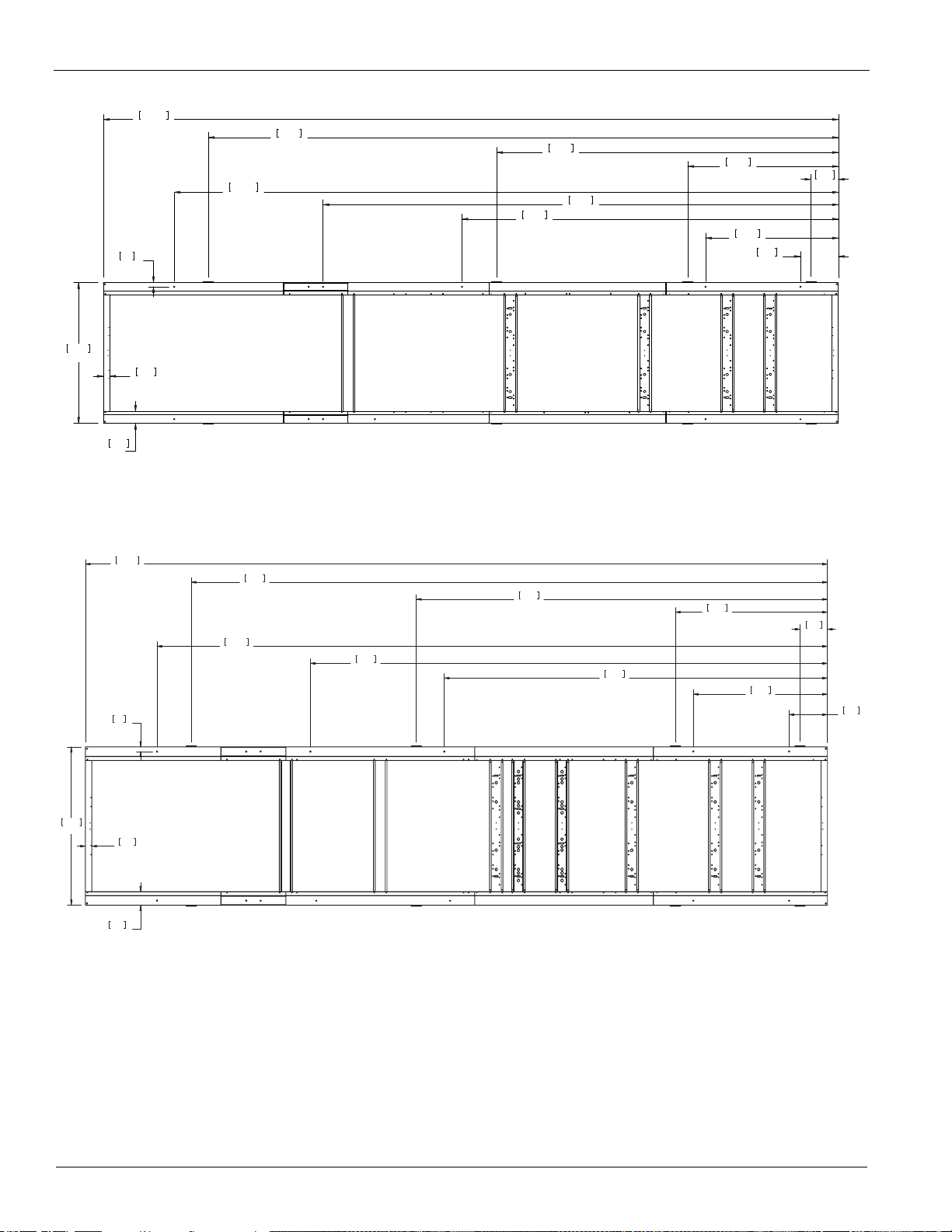
Lifting & Mounting Dimensions (non-VFD)
457.5
11620
23.6
600
82.7
2100
234.2
5949
320.8
8147
413.4
10499
87.6
2225
2.6
66
7.5
190
3.9
100
17.0
431
93.7
2381
212.6
5401
392.2
9962
CONTROL BOX
L1
M1M3
L3L5
M5M7
L7
M9
L2
M2M4
L4L6
M6
M8
L8
M10
AWS 24 FAN DIM. DWG
331426608C020A
457.5
11620
23.6
600
82.7
2100
236.2
6000
413.4
10499
87.6
2225
2.6
66
7.5
190
3.9
100
318.8
8096
17.0
431
93.7
2381
253.4
6438
392.2
9962
CONTROL BOX
L1L3
L4 L2L6
L5L7
L8
M1M3
M4 M2M6
M5M7
M8
M10
M9
AWS 3C-24 FAN DIM. DWG
331426610D020A
Figure 22: AWS400BDP, AWS410BDH (non-VFD)
Figure 23: AWS450BTS/H, AW S470BTS (non-VFD)
48 IM 1167
Page 49

Figure 24: AWS475BTH, AWS500BTS (non-VFD)
492.9
12520
23.6
600
82.7
2100
236.2
6000
87.6
2225
7.5
190
3.9
100
318.8
8096
413.4
10501
17.0
431
93.7
2381
253.4
6438
415.9
10564
CONTROL BOX
L1L3
L4 L2L6
L5
L7
L8
M1M3
M4 M2M6
M5M7
M8
M10
M9
AWS 3C-26 FAN DIM. DWG
331426611D020A
528.4
13420
23.6
600
82.7
2100
236.2
6000
472.4
12000
87.6
2225
2.6
66
7.5
190
3.9
100
354.3
9000
17.0
431
93.7
2381
253.4
6436
423.6
10761
CONTROL BOX
L1L3
L4 L2L6
L5L7
L8
M1M3
M4 M2M6
M5M7
M8
M10
M9
AWS 3C-28 FAN DIM. DWG
331426612D020B
563.8
14320
23.6
600
82.7
2100
236.2
6000
543.3
13800
87.6
2225
2.6
66
7.5
190
3.9
100
381.7
9694
17.0
431
93.7
2381
253.4
6436
462.5
11746
CONTROL BOX
L1L3
L4 L2L6
L5
L7
L8
M1M3
M4 M2M6
M5
M7
M8
M10
M9
AWS 3C-30 FAN DIM. DWG
331426613D020B
Figure 25: AWS500BTH, AWS525BTS (non-VFD)
Lifting & Mounting Dimensions (non-VFD)
Figure 26: AWS530BTH, AWS550BTS (non-VFD)
IM 1167 49
Page 50

Lifting & Mounting Dimensions (VFD)
L2 M2M4L4M6L6M8
333687301
AWS-B-0B WITH VFD 10 FAN DIM. DWG
333687300C
2 2
0
0
6.0
152
24.0
610
68.0
1727
96.0
2438
143.2
3638
200.3
5089
205.0
5208
240.9
6118
87.6
2225
7.5
190
3.9
100
2.6
66
Ø .750 TYP.
19
CONTROL BOX
L1 M1M3L3M5L5M7
BOTTOM VIEW
333687302
AWS-B-0B WITH VFD 12 FAN DIM. DWG
3336873 00C
2 2
0
0
6.0
152
24.0
610
68.0
1727
96.0
2438
143.2
3638
200.3
5089
205.0
5208
240.9
6118
87.6
2225
7.5
190
3.9
100
2.6
66
Ø .750 T YP.
19
CONTROL BOX
L1 M1M3L3M5L5M7
BOTTOM VIEW
M2L2M4L4M6L6M8
Lifting & Mounting Dimensions (VFD)
Figure 27: AWS170BDS (VFD)
Figure 28: AWS190BDS, AWS200BDS, AWS210BDH (VFD)
50 IM 1167
Page 51

Lifting & Mounting Dimensions (VFD)
AWS-B-0B WITH VFD 14 FAN DIM. DWG
333687300C
2 2
0
0
6.0
152
24.0
610
68.0
1727
96.0
2438
143.2
3638
200.3
5089
205.0
5208
260.2
6608
276.3
7018
87.6
2225
7.5
190
3.9
100
2.6
66
Ø .750 TYP.
19
CONTROL BOX
L1 M1M3L3M5L5M7
BOTTOM VIEW
M2L2M4L4M6L6M8
M9
M10
333687304
AWS-B-0B WITH VFD 16 FAN DIM. DWG
00
D
2 2
3336873
0
0
6.0
152
24.0
610
68.0
1727
96.0
2438
143.2
3638
200.3
5089
205.0
5208
295.6
7508
311.7
7918
87.6
2225
7.5
190
3.9
100
2.6
66
Ø .750 TYP.
19
CONTROL BOX
L1 M1M3L3M5L5M7
BOTTOM VIEW
M2L2M4L4M6L6M8
M9
M10
Figure 29: AWS230BDH, AWS250BDH (VFD)
Figure 30: AWS240BDP, AWS280BDH, AWS300BDH (VFD)
IM 1167 51
Page 52

Lifting & Mounting Dimensions (VFD)
AWS-B-0B WITH VFD 18 FAN DIM. DWG
00
2 2
3336873
0
0
6.0
152
24.0
610
68.0
1727
96.0
2438
143.2
3638
200.3
5089
205.0
5208
331.0
8408
347.2
8818
87.6
2225
7.5
190
3.9
100
2.6
66
Ø .750 TYP.
19
CONTROL BOX
L1 M1
M3L3M5L5M7
BOTTOM VIEW
M2
L2M4L4M6
L6M8
M9
M10
333687306
AWS-B-0B WITH VFD 20 FAN DIM. DWG
00
D
2 2
3336873
0
0
6.0
152
24.0
610
68.0
1727
96.0
2438
143.2
3638
205.0
5208
246.4
6259
366.4
9306
382.5
9716
87.6
2225
7.5
190
3.9
100
2.6
66
Ø .750 TYP.
19
CONTROL BOX
L1 M1
M3L3M5L5 M7
BOTTOM VIEW
M2
L2M4L4M6
L6 M8
M9
M10
87.6
2225
2.6
66
7.5
190
3.9
100
460.2
11688
120.8
3068
61.7
1568
396.8
10078
34.3
872
250.8
6369
131.9
3349
368.2
9353
274.3
6968
16.1
410
CONTROL BOX
L1
M9 M3
L3
M5
L5
M7 M1
L2
M10
M4
L4
M6
L6
M8
L8
L7
M2
332824701
AWS-B W/ VFD 22 FAN DIM. DWG
Figure 31: AWS265BDP, AWS290BDP (VFD)
Figure 32: AWS310BDP, AWS330BDH/P, AWS350BDH (VFD)
Figure 33: AWS365BDP, 390BDH (VFD)
52 IM 1167
Page 53

Figure 34: AWS400BDP, AWS410BDH (VFD)
87.6
2225
2.6
66
7.5
190
3.9
100
495.6
12589
120.8
3068
61.7
1568
451.6
11470
34.3
872
250.8
6369
131.9
3349
430.3
10930
272.3
6918
358.9
9116
16.1
410
CONTROL BOX
L1
M1M3
L3
M5
L5
M7M9
M11
M12
L2
M2M4
L4L6
M6
L8
M8
M10
L7
332824801
AWS-B W/VFD 24 2C FAN DIM. DWG
87.6
2225
2.6
66
7.5
190
3.9
100
495.6
12589
120.8
3068
61.7
1568
451.6
11470
34.3
872
291.5
7404
131.9
3349
430.3
10930
274.3
6968
356.9
9065
16.1
410
CONTROL BOX
L1
M1M3
L3
M5
L5
M7M9
M11
L2
M2M4
L4
M6
L6
M8
L8
L7
M10M12
332824901
AWS-B W VFD 24 3C FAN DIM. DWG
87.6
2225
7.5
190
3.9
100
531.0
13488
120.8
3068
61.7
1568
34.3
872
291.5
7404
131.9
3349
453.9
11528
274.3
6968
356.9
9065
451.5
11469
16.1
410
CONTROL BOX
L1
M1M3
L3
M5
L5
M7M9
M11
M12
L2
M2M4
L4
M6
L6
M8
L8
L7
M10
332825001
AWS-B WITH VFD 26 FAN DIM. DWG
Figure 35: AWS450BTH (VFD)
Lifting & Mounting Dimensions (VFD)
Figure 36: AWS475BTH (VFD)
IM 1167 53
Page 54

Lifting & Mounting Dimensions (VFD)
87.6
2225
2.6
66
7.5
190
3.9
100
566.5
14388
120.8
3068
61.7
1568
510.6
12968
34.3
872
291.5
7404
131.9
3349
461.8
11729
274.3
6968
392.4
9968
16.1
410
CONTROL BOX
L1
M1M3
L3
M5
L5
M7M9
M12
L2
M2M4
L4
M6
L6
M8
L8
L7
M10
M11
332825101
AWS-B W/ VFD 28 FAN DIM. DWG
87.6
2225
2.6
66
7.5
190
3.9
100
601.9
15288
120.8
3068
61.7
1568
581.4
14768
34.3
872
291.5
7404
131.9
3349
500.6
12714
274.3
6968
419.8
10662
16.1
410
CONTROL BOX
L1
M1M3
L3
M5
L5
M7M9
M12
L2
M2M4
L4
M6
L6
M8
L8
L7
M10
M11
332825201
AWS-B W/ VFD 30 FAN DIM. DWG
Figure 37: AWS500BTH (VFD)
Figure 38: AWS530BTH (VFD)
54 IM 1167
Page 55

Isolator Locations and Kit Numbers
MOUNT MATERIAL TO BE DURULENE RUBBER.1.
MOLDED STEEL AND ELASTOMER MOUNT FOR2.
OUTDOOR SERVICE CONDITIONS.
DRAWING NUMBER 3314814
1.13 ± .25
APPROX.
1.63
.38
DURULENE
MATERIAL
RAISED GRIP RIBS
3.00
3.75
5.00
6.25
3.87
.56 TYP.
4.63R.28
TYP.R.250
TYP .
R.750 TYP .
RECESSED
GRIP RIBS
ø
.500-13NC-2B
R4
R4
VM&C
VM&C
Isolator Locations and Kit Numbers
Transfer the unit as indicated in the Installation and
Maintenance Manual, IM 1167, available on
www.DaikinMcQuay.com. In all cases, set the unit in place
and level with a spirit level. When spring-type isolators are
required, install springs running under the main unit supports.
The unit should be set initially on shims or blocks at the listed
spring free height. When all piping, wiring, flushing, charging,
etc., is completed, the springs are adjusted upward to loosen
the blocks or shims that are then removed.
A rubber anti-skid pad should be used under isolators if holddown bolts are not used.
Installation of spring isolators requires flexible piping
connections and at least three feet of flexible electrical conduit
to avoid straining the piping and transmitting vibration and
noise.
Mounting locations for each model can be found in the Lifting
& Mounting Dimensions beginning on page 44
Figure 39: Spring Isolators - CP-4
Figure 40: Neoprene-in-Shear Isolators - RP-4
IM 1167 55
Page 56

Isolator Locations and Kit Numbers
UN IT S IZ E
# OF
FANS
Kit P/NM1M2M3M4M5M6M7M8M9M10
332620800 332620800 332620800 332620800 332620500 332620500
Dark Green Dark Green Dark Green Dark Green Black Black
332620800 332620800 332620800 332620800 332620500 332620500
Dark Green Dark Green Dark Green Dark Green Black Black
332620800 332620800 332620800 332620800 332620500 332620500
Dark Green Dark Green Dark Green Dark Green Black Black
332620900 332620900 332620800 332620800 332620500 332620500 332620400 332620400
Gray Gray Dark Green Dark Green Black Black Red Red
332620900 332620900 332620800 332620800 332620500 332620500 332620400 332620400
Gray Gray Dark Green Dark Green Black Black Red Red
332620900 332620900 332620800 332620800 332620600 332620600 332620400 332620400
Gray Gray Dark Green Dark Green Dark Purple Dark Purple Red Red
332620900 332620900 332620800 332620800 332620600 332620600 332620400 332620400
Gray Gray Dark Green Dark Green Dark Purple Dark Purple Red Red
332620900 332620900 332620900 332620900 332620800 332620800 332620500 332620500
Gray Gray Gray Gray Dark Green Dark Green Black Black
332620900 332620900 332620900 332620900 332620800 332620800 332620500 332620500
Gray Gray Gray Gray Dark Green Dark Green Black Black
332620900 332620900 332620900 332620900 332620800 332620800 332620800 332620800
Gray Gray Gray Gray Dark Green Dark Green Dark Green Dark Green
332620900 332620900 332620900 332620900 332620800 332620800 332620800 332620800
Gray Gray Gray Gray Dark Green Dark Green Dark Green Dark Green
332620900 332620900 332620900 332620900 332620800 332620800 332620800 332620800 332620500 332620500
Gray Gray Gray Gray Dark Green Dark Green Dark Green Dark Green Black Black
332620900 332620900 332620900 332620900 332620800 332620800 332620800 332620800 332620500 332620500
Gray Gray Gray Gray Dark Green Dark Green Dark Green Dark Green Black Black
332620900 332620900 332620900 332620900 332620800 332620800 332620800 332620800 332620500 332620500
Gray Gray Gray Gray Dark Green Dark Green Dark Green Dark Green Black Black
332621000 332621000 332621000 332621000 332620900 332620900 332620800 332620800 332620500 332620500
White White White White Gray Gray Dark Green Dark Green Black Black
332621000 332621000 332621000 332621000 332620900 332620900 332620800 332620800 332620500 332620500
White White White White Gray Gray Dark Green Dark Green Black Black
332620800 332620800 332620800 332620800 332620500 332620500
Dark Green Dark Green Dark Green Dark Green Black Black
332620900 332620900 332620800 332620800 332620500 332620500 332620400 332620400
Gray Gray Dark Green Dark Green Black Black Red Red
332620900 332620900 332620800 332620800 332620500 332620500 332620400 332620400
Gray Gray Dark Green Dark Green Black Black Red Red
332620900 332620900 332620800 332620800 332620600 332620600 332620400 332620400
Gray Gray Dark Green Dark Green Dark Purple Dark Purple Red Red
332620900 332620900 332620800 332620800 332620600 332620600 332620400 332620400
Gray Gray Dark Green Dark Green Dark Purple Dark Purple Red Red
332620900 332620900 332620900 332620900 332620800 332620800 332620500 332620500
Gray Gray Gray Gray Dark Green Dark Green Black Black
332620900 332620900 332620900 332620900 332620800 332620800 332620500 332620500
Gray Gray Gray Gray Dark Green Dark Green Black Black
332620900 332620900 332620900 332620900 332620800 332620800 332620600 332620600
Gray Gray Gray Gray Dark Green Dark Green Dark Purple Dark Purple
332620900 332620900 332620900 332620900 332620800 332620800 332620600 332620600 332620400 332620400
Gray Gray Gray Gray Dark Green Dark Green Dark Purple Dark Purple Red Red
332620900 332620900 332620900 332620900 332620800 332620800 332620800 332620800 332620500 332620500
Gray Gray Gray Gray Dark Green Dark Green Dark Green Dark Green Black Black
332620900 332620900 332620900 332620900 332620800 332620800 332620800 332620800 332620500 332620500
Gray Gray Gray Gray Dark Green Dark Green Dark Green Dark Green Black Black
332621000 332621000 332621000 332621000 332620900 332620900 332620800 332620800 332620500 332620500
White White White White Gray Gray Dark Green Dark Green Black Black
332621000 332621000 332621000 332621000 332620900 332620900 332620800 332620800 332620500 332620500
White White White White Gray Gray Dark Green Dark Green Black Black
332620800 332620800 332620800 332620800 332620600 332620600 332620500 332620500
Dark Green Dark Green Dark Green Dark Green Dark Purple Dark Purple Black Black
332620900 332620900 332620900 332620900 332620800 332620800 332620500 332620500
Gray Gray Gray Gray Dark Green Dark Green Black Black
332620900 332620900 332620900 332620900 332620800 332620800 332620500 332620500
Gray Gray Gray Gray Dark Green Dark Green Black Black
332620900 332620900 332620900 332620900 332620800 332620800 332620800 332620800
Gray Gray Gray Gray Dark Green Dark Green Dark Green Dark Green
332620900 332620900 332620900 332620900 332620800 332620800 332620800 332620800
Gray Gray Gray Gray Dark Green Dark Green Dark Green Dark Green
332620900 332620900 332620900 332620900 332620800 332620800 332620800 332620800
Gray Gray Gray Gray Dark Green Dark Green Dark Green Dark Green
332620900 332620900 332620900 332620900 332620800 332620800 332620600 332620600 332620500 332620500
Gray Gray Gray Gray Dark Green Dark Green Dark Purple Dark Purple Black Black
332320847
332320846
332320846
332320847
332320850
332320835
332320835
332320828
332320847
332320850
332320828
332320828
332320828
332320829
332320829
332320846
AWS210BDS 12
N/A
10
N/A
N/A N/A
N/A
N/A
N/A
N/A
N/A
N/A
N/A
AWS225BDS 12
AWS250BDS 14
N/A
AWS190BDS
N/A N/A
N/A N/A
N/A N/A
20
N/A
N/A
AWS260BDS 14
AWS290BDS 16
N/A N/A
24
16
22
AWS450BTS 24
AWS400BTS
AWS375BDS 20
AWS310BDS
AWS350BDS
332320850
N/A
AWS500BTS 26
22AWS425BTS
N/A
N/A N/A
AWS470BTS
332320848
332320848
N/A
N/A
N/A
N/A
AWS525BTS 28
AWS550BTS 30
AWS210BDH 12
N/AN/A N/A
N/A
AWS250BDH 14
332320829
332320829
AWS280BDH 16
N/A
N/A N/A
N/A
AWS230BDH 14
332320846
AWS300BDH 16
N/A
N/A
AWS330BDH 20
AWS350BDH 20
N/A
332320847
AWS390BDH 22
N/A
332320834
332320850
332320850
AWS410BDH
332320849
24
AWS450BTH 24
332320835
332320835
26
AWS530BTH 30
AWS500BTH
N/A N/A
N/A
N/A
28
AWS475BTH
AWS240BDP 16 332320830
332320847
N/A
AWS310BDP
332320848
332320833
N/A N/A
N/A
20
332320848
332320848
AWS265BDP 18
AWS290BDP 20 332320847
N/A
AWS400BDP 24
AWS365BDP 22
N/A
N/A
AWS330BDP 22
N/A
N/A N/A
N/A N/A
Table 40: Spring Isolators (for 60Hz non-VFD Units with Aluminum Fin Condensers)
56 IM 1167
Page 57

Isolator Locations and Kit Numbers
UNIT SIZ E
# OF
FANS
Kit P/NM1M2M3M4M5M6M7M8M9M10
332620800 332620800 332620800 332620800 332620600 332620600
Dark Green Dark Green Dark Green Dark Green Dark Purple Dark Purple
332620900 332620900 332620800 332620800 332620600 332620600
Gray Gray Dark Green Dark Green Dark Purple Dark Purple
332620900 332620900 332620800 332620800 332620600 332620600
Gray Gray Dark Green Dark Green Dark Purple Dark Purple
332620900 332620900 332620800 332620800 332620600 332620600 332620400 332620400
Gray Gray Dark Green Dark Green Dark Purple Dark Purple Red Red
332620900 332620900 332620800 332620800 332620600 332620600 332620400 332620400
Gray Gray Dark Green Dark Green Dark Purple Dark Purple Red Red
332620900 332620900 332620900 332620900 332620800 332620800 332620500 332620500
Gray Gray Gray Gray Dark Green Dark Green Black Black
332620900 332620900 332620900 332620900 332620800 332620800 332620500 332620500
Gray Gray Gray Gray Dark Green Dark Green Black Black
332620900 332620900 332620900 332620900 332620800 332620800 332620600 332620600
Gray Gray Gray Gray Dark Green Dark Green Dark Purple Dark Purple
332620900 332620900 332620900 332620900 332620800 332620800 332620600 332620600
Gray Gray Gray Gray Dark Green Dark Green Dark Purple Dark Purple
332621000 332621000 332620900 332620900 332620900 332620900 332620800 332620800
White White Gray Gray Gray Gray Dark Green Dark Green
332621000 332621000 332620900 332620900 332620900 332620900 332620800 332620800
White White Gray Gray Gray Gray Dark Green Dark Green
332621000 332621000 332621000 332621000 332620800 332620800 332620800 332620800 332620500 332620500
White White White White Dark Green Dark Green Dark Green Dark Green Black Black
332621000 332621000 332621000 332621000 332620800 332620800 332620800 332620800 332620600 332620600
White White White White Dark Green Dark Green Dark Green Dark Green Dark Purple Dark Purple
332621000 332621000 332621000 332621000 332620900 332620900 332620800 332620800 332620800 332620800
White White White White Gray Gray Dark Green Dark Green Dark Green Dark Green
332621000 332621000 332621000 332621000 332620900 332620900 332620800 332620800 332620800 332620800
White White White White Gray Gray Dark Green Dark Green Dark Green Dark Green
332621000 332621000 332621000 332621000 332620900 332620900 332620800 332620800 332620800 332620800
White White White White Gray Gray Dark Green Dark Green Dark Green Dark Green
332620800 332620800 332620800 332620800 332620800 332620800
Dark Green Dark Green Dark Green Dark Green Dark Green Dark Green
332620900 332620900 332620800 332620800 332620600 332620600 332620400 332620400
Gray Gray Dark Green Dark Green Dark Purple Dark Purple Red Red
332620900 332620900 332620800 332620800 332620600 332620600 332620400 332620400
Gray Gray Dark Green Dark Green Dark Purple Dark Purple Red Red
332620900 332620900 332620900 332620900 332620800 332620800 332620500 332620500
Gray Gray Gray Gray Dark Green Dark Green Black Black
332620900 332620900 332620900 332620900 332620800 332620800 332620500 332620500
Gray Gray Gray Gray Dark Green Dark Green Black Black
332620900 332620900 332620900 332620900 332620800 332620800 332620600 332620600
Gray Gray Gray Gray Dark Green Dark Green Dark Purple Dark Purple
332620900 332620900 332620900 332620900 332620800 332620800 332620600 332620600
Gray Gray Gray Gray Dark Green Dark Green Dark Purple Dark Purple
332621000 332621000 332620900 332620900 332620900 332620900 332620800 332620800
White White Gray Gray Gray Gray Dark Green Dark Green
332621000 332621000 332621000 332621000 332620800 332620800 332620800 332620800 332620500 332620500
White White White White Dark Green Dark Green Dark Green Dark Green Black Black
332621000 332621000 332621000 332621000 332620800 332620800 332620800 332620800 332620600 332620600
White White White White Dark Green Dark Green Dark Green Dark Green Dark Purple Dark Purple
332621000 332621000 332621000 332621000 332620900 332620900 332620800 332620800 332620800 332620800
White White White White Gray Gray Dark Green Dark Green Dark Green Dark Green
332621000 332621000 332621000 332621000 332620900 332620900 332620800 332620800 332620800 332620800
White White White White Gray Gray Dark Green Dark Green Dark Green Dark Green
332621000 332621000 332621000 332621000 332620900 332620900 332620800 332620800 332620800 332620800
White White White White Gray Gray Dark Green Dark Green Dark Green Dark Green
332620900 332620900 332620900 332620900 332620800 332620800 332620500 332620500
Gray Gray Gray Gray Dark Green Dark Green Black Black
332620900 332620900 332620900 332620900 332620800 332620800 332620600 332620600
Gray Gray Gray Gray Dark Green Dark Green Dark Purple Dark Purple
332620900 332620900 332620900 332620900 332620800 332620800 332620800 332620800
Gray Gray Gray Gray Dark Green Dark Green Dark Green Dark Green
332620900 332620900 332620900 332620900 332620800 332620800 332620800 332620800
Gray Gray Gray Gray Dark Green Dark Green Dark Green Dark Green
332620900 332620900 332620900 332620900 332620800 332620800 332620800 332620800
Gray Gray Gray Gray Dark Green Dark Green Dark Green Dark Green
332621000 332621000 332620900 332620900 332620900 332620900 332620800 332620800
White White Gray Gray Gray Gray Dark Green Dark Green
332621000 332621000 332621000 332621000 332620800 332620800 332620800 332620800 332620500 332620500
White White White White Dark Green Dark Green Dark Green Dark Green Black Black
N/A N/A
N/A N/A
332320831
332320831
332320846
332320846
332320847
332320847
332320853
332320837
332320832
332320848
332320848
AWS400BDP 24 332320836
N/A N/A
AWS330BDP
AWS365BDP 22 332320832
22 332320848
N/A N/A
AWS310BDP 20
AWS290BDP 20
N/A N/A
N/A N/A
N/A N/A
AWS240BDP
AWS265BDP 18 332320849
16 332320847
N/A N/A
AWS475BTH 26 332320853
N/A
AWS530BTH 30
AWS500BTH 28 332320853
332320853
N/A
AWS450BTH 24 332320837
AWS410BDH 24 332320836
AWS390BDH 22 332320832
N/A N/A
N/A N/A
AWS330BDH
AWS350BDH 20 332320849
20 332320849
16
AWS280BDH 16
N/A N/A
N/A N/A
N/A N/A
AWS230BDH
AWS250BDH 14 332320846
14 332320846
N/A N/A
AWS550BTS 30 332320853
AWS210BDH 12 332320852
26 332320853
N/A N/A N/AN/A
AWS450BTS 24 332320836
AWS470BTS 24
AWS400BTS
AWS425BTS 22 332320832
22
N/A
N/A N/A
N/A N/A
N/A N/A
N/A
AWS290BDS
AWS310BDS 16 332320847
16 332320847
N/A N/A
N/A
N/A N/A
N/A
N/A N/A
AWS375BDS 20
N/A
N/A
N/A
332320849
AWS350BDS 20 332320849
N/A
AWS500BTS
AWS525BTS 28
AWS300BDH
N/A N/A
12
AWS250BDS
AWS260BDS 14
AWS210BDS
AWS225BDS 12
14
AWS190BDS 10 332320851
N/A N/A
Table 41: Spring Isolators (for 60Hz non-VFD Units with Copper Fin Condensers)
IM 1167 57
Page 58

Isolator Locations and Kit Numbers
UN IT S IZ E
# OF
FANS
Kit P/NM1M2M3M4M5M6M7M8M9M10
331481404 331481404 331481403 331481403 331481402 331481402
Gray Gray Green Green Red Red
331481404 331481404 331481403 331481403 331481402 331481402
Gray Gray Green Green Red Red
331481404 331481404 331481403 331481403 331481402 331481402
Gray Gray Green Green Red Red
331481404 331481404 331481403 331481403 331481402 331481402 331481401 331481401
Gray Gray Green Green Red Red Brown Brown
331481404 331481404 331481403 331481403 331481402 331481402 331481401 331481401
Gray Gray Green Green Red Red Brown Brown
331481404 331481404 331481403 331481403 331481402 331481402 331481401 331481401
Gray Gray Green Green Red Red Brown Brown
331481404 331481404 331481403 331481403 331481402 331481402 331481401 331481401
Gray Gray Green Green Red Red Brown Brown
331481404 331481404 331481404 331481404 331481403 331481403 331481402 331481402
Gray Gray Gray Gray Green Green Red Red
331481404 331481404 331481404 331481404 331481403 331481403 331481402 331481402
Gray Gray Gray Gray Green Green Red Red
331481404 331481404 331481404 331481404 331481403 331481403 331481403 331481403
Gray Gray Gray Gray Green Green Green Green
331481404 331481404 331481404 331481404 331481403 331481403 331481403 331481403
Gray Gray Gray Gray Green Green Green Green
331481405 331481405 331481404 331481404 331481404 331481404 331481402 331481402 331481401 331481401
Purple Purple Gray Gray Gray Gray Red Red Brown Brown
331481405 331481405 331481404 331481404 331481404 331481404 331481402 331481402 331481401 331481401
Purple Purple Gray Gray Gray Gray Red Red Brown Brown
331481405 331481405 331481404 331481404 331481404 331481404 331481403 331481403 331481402 331481402
Purple Purple Gray Gray Gray Gray Green Green Red Red
331481405 331481405 331481404 331481404 331481404 331481404 331481403 331481403 331481402 331481402
Purple Purple Gray Gray Gray Gray Green Green Red Red
331481405 331481405 331481405 331481405 331481404 331481404 331481403 331481403 331481402 331481402
Purple Purple Purple Purple Gray Gray Green Green Red Red
331481404 331481404 331481403 331481403 331481402 331481402
Gray Gray Green Green Red Red
331481404 331481404 331481403 331481403 331481402 331481402 331481401 331481401
Gray Gray Green Green Red Red Brown Brown
331481404 331481404 331481403 331481403 331481402 331481402 331481401 331481401
Gray Gray Green Green Red Red Brown Brown
331481404 331481404 331481403 331481403 331481402 331481402 331481401 331481401
Gray Gray Green Green Red Red Brown Brown
331481404 331481404 331481403 331481403 331481402 331481402 331481401 331481401
Gray Gray Green Green Red Red Brown Brown
331481404 331481404 331481404 331481404 331481403 331481403 331481402 331481402
Gray Gray Gray Gray Green Green Red Red
331481404 331481404 331481404 331481404 331481403 331481403 331481402 331481402
Gray Gray Gray Gray Green Green Red Red
331481404 331481404 331481404 331481404 331481403 331481403 331481403 331481403
Gray Gray Gray Gray Green Green Green Green
331481405 331481405 331481404 331481404 331481404 331481404 331481402 331481402 331481401 331481401
Purple Purple Gray Gray Gray Gray Red Red Brown Brown
331481405 331481405 331481404 331481404 331481404 331481404 331481402 331481402 331481401 331481401
Purple Purple Gray Gray Gray Gray Red Red Brown Brown
331481405 331481405 331481404 331481404 331481404 331481404 331481403 331481403 331481402 331481402
Purple Purple Gray Gray Gray Gray Green Green Red Red
331481405 331481405 331481404 331481404 331481404 331481404 331481403 331481403 331481402 331481402
Purple Purple Gray Gray Gray Gray Green Green Red Red
331481405 331481405 331481405 331481405 331481404 331481404 331481403 331481403 331481402 331481402
Purple Purple Purple Purple Gray Gray Green Green Red Red
331481404 331481404 331481403 331481403 331481402 331481402 331481401 331481401
Gray Gray Green Green Red Red Brown Brown
331481404 331481404 331481404 331481404 331481403 331481403 331481402 331481402
Gray Gray Gray Gray Green Green Red Red
331481404 331481404 331481404 331481404 331481403 331481403 331481402 331481402
Gray Gray Gray Gray Green Green Red Red
331481404 331481404 331481404 331481404 331481403 331481403 331481402 331481402
Gray Gray Gray Gray Green Green Red Red
331481404 331481404 331481404 331481404 331481403 331481403 331481402 331481402
Gray Gray Gray Gray Green Green Red Red
331481404 331481404 331481404 331481404 331481403 331481403 331481403 331481403
Gray Gray Gray Gray Green Green Green Green
331481405 331481405 331481404 331481404 331481404 331481404 331481402 331481402 331481401 331481401
Purple Purple Gray Gray Gray Gray Red Red Brown Brown
N/A
16 332325829
N/A
332325830
N/A
22
N/A
N/A
332325843
N/A
24 332325834
22 332325830
N/A N/A
20
N/A
N/A
N/A
N/A
N/A N/A
N/A
N/A
N/A
N/A
N/A
N/A
N/A
N/A
N/A
N/A
N/A
AWS290BDP
AWS400BDP
AWS310BDP
AWS330BDP
AWS500BTS
AWS550BTS
AWS450BTH
AWS500BTH
AWS240BDP
AWS265BDP
AWS365BDP
AWS210BDS
N/A
12
AWS190BDS
24 332325834
22 332325843
N/A
AWS330BDH
AWS530BTH
AWS410BDH
AWS390BDH
AWS350BDH
20 332325830
18 332325830
332325845
332325834
30
28 332325844
AWS475BTH 26 332325844
24
12
332325829AWS230BDH
AWS210BDH
AWS250BDH
N/A
16 332325829
AWS280BDH 16
AWS300BDH
14
N/A N/A
332325828
332325830
332325829
N/A
N/A
N/A
N/A
N/A
N/A
N/A
AWS260BDS
12
AWS250BDS 14
332325828
14 332325829
332325829
AWS290BDS 16 332325829
N/A
N/A
A WS 3 10 B D S 16
AWS350BDS 20 332325830
AWS375BDS 332325830
N/A
N/A
N/AN/A
332325829
22 332325843
20
N/A N/A
AWS425BTS 22
N/A N/A
AWS400BTS
AWS450BTS 24 332325834
30 332325845
AWS525BTS
AWS470BTS
28 332325844
20
33232582914
33232583424
332325843
20 332325830
26 332325844
332325828
10 332325828
N/A N/A
AWS225BDS
N/A
N/A N/A
N/A N/A
N/A
N/A
N/A
N/A
Table 42: RIS Isolators (for 60Hz non-VFD Units with Aluminum Fin Condensers)
58 IM 1167
Page 59

Table 43: RIS Isolators (for 60Hz non-VFD Units with Copper Fin Condensers)
UNIT SIZ E
# OF
FANS
Kit P/NM1M2M3M4M5M6M7M8M9M10
331481404 331481404 331481403 331481403 331481402 331481402
Gray Gray Green G reen Red Red
331481404 331481404 331481403 331481403 331481402 331481402
Gray Gray Green G reen Red Red
331481404 331481404 331481403 331481403 331481402 331481402
Gray Gray Green G reen Red Red
331481404 331481404 331481403 331481403 331481402 331481402 331481401 331481401
Gray Gray Green G reen Red Red Brown Brown
331481404 331481404 331481403 331481403 331481402 331481402 331481401 331481401
Gray Gray Green G reen Red Red Brown Brown
331481404 331481404 331481404 331481404 331481402 331481402 331481401 331481401
Gray Gray Gray Gray Red Red Brown Brown
331481404 331481404 331481404 331481404 331481402 331481402 331481401 331481401
Gray Gray Gray Gray Red Red Brown Brown
331481405 331481405 331481404 331481404 331481404 331481404 331481403 331481403
Purple Purple Gray Gray Gray Gray Green Green
331481405 331481405 331481404 331481404 331481404 331481404 331481403 331481403
Purple Purple Gray Gray Gray Gray Green Green
331481405 331481405 331481404 331481404 331481404 331481404 331481403 331481403
Purple Purple Gray Gray Gray Gray Green Green
331481405 331481405 331481404 331481404 331481404 331481404 331481403 331481403
Purple Purple Gray Gray Gray Gray Green Green
331481405 331481405 331481404 331481404 331481403 331481403 331481402 331481402 331481402 331481402
Purple Purple Gray Gray Green Green Red Red Red Red
331481405 331481405 331481404 331481404 331481403 331481403 331481403 331481403 331481402 331481402
Purple Purple Gray Gray Green Green Green Green Red Red
331481405 331481405 331481405 331481405 331481404 331481404 331481403 331481403 331481402 331481402
Purple Purple Purple Purple Gray Gray Green Green Red Red
331481405 331481405 331481405 331481405 331481404 331481404 331481403 331481403 331481402 331481402
Purple Purple Purple Purple Gray Gray Green Green Red Red
331481405 331481405 331481405 331481405 331481404 331481404 331481403 331481403 331481402 331481402
Purple Purple Purple Purple Gray Gray Green Green Red Red
331481404 331481404 331481403 331481403 331481402 331481402
Gray Gray Green G reen Red Red
331481404 331481404 331481403 331481403 331481402 331481402 331481401 331481401
Gray Gray Green G reen Red Red Brown Brown
331481404 331481404 331481403 331481403 331481402 331481402 331481401 331481401
Gray Gray Green G reen Red Red Brown Brown
331481404 331481404 331481404 331481404 331481402 331481402 331481401 331481401
Gray Gray Gray Gray Red Red Brown Brown
331481404 331481404 331481404 331481404 331481402 331481402 331481401 331481401
Gray Gray Gray Gray Red Red Brown Brown
331481405 331481405 331481404 331481404 331481404 331481404 331481403 331481403
Purple Purple Gray Gray Gray Gray Green Green
331481405 331481405 331481404 331481404 331481404 331481404 331481403 331481403
Purple Purple Gray Gray Gray Gray Green Green
331481405 331481405 331481404 331481404 331481404 331481404 331481403 331481403
Purple Purple Gray Gray Gray Gray Green Green
331481405 331481405 331481404 331481404 331481403 331481403 331481402 331481402 331481402 331481402
Purple Purple Gray Gray Green Green Red Red Red Red
331481405 331481405 331481404 331481404 331481403 331481403 331481403 331481403 331481402 331481402
Purple Purple Gray Gray Green Green Green Green Red Red
331481405 331481405 331481405 331481405 331481404 331481404 331481403 331481403 331481402 331481402
Purple Purple Purple Purple Gray Gray Green Green Red Red
331481405 331481405 331481405 331481405 331481404 331481404 331481403 331481403 331481402 331481402
Purple Purple Purple Purple Gray Gray Green Green Red Red
331481405 331481405 331481405 331481405 331481404 331481404 331481403 331481403 331481402 331481402
Purple Purple Purple Purple Gray Gray Green Green Red Red
331481404 331481404 331481404 331481404 331481404 331481404 331481402 331481402
Gray Gray Gray Gray Gray Gray Red Red
331481404 331481404 331481404 331481404 331481404 331481404 331481402 331481402
Gray Gray Gray Gray Gray Gray Red Red
331481404 331481404 331481404 331481404 331481404 331481404 331481402 331481402
Gray Gray Gray Gray Gray Gray Red Red
331481405 331481405 331481404 331481404 331481404 331481404 331481403 331481403
Purple Purple Gray Gray Gray Gray Green Green
331481405 331481405 331481404 331481404 331481404 331481404 331481403 331481403
Purple Purple Gray Gray Gray Gray Green Green
331481405 331481405 331481404 331481404 331481404 331481404 331481403 331481403
Purple Purple Gray Gray Gray Gray Green Green
331481405 331481405 331481404 331481404 331481403 331481403 331481402 331481402 331481402 331481402
Purple Purple Gray Gray Green Green Red Red Red Red
N/A N/A
10
N/A
332325833
N/A N/A
AWS400BDP 24 332325835
N/A
N/A N/A
N/A N/A
N/A
AWS330BDP
AWS365BDP 22 332325833
22
AWS310BDP 20 332325833
AWS290BDP 20 332325831
N/A N/A
AWS240BDP
AWS265BDP 18 332325831
16 332325831
N/A N/A
AWS530BTH 30 332325845
AWS500BTH 28 332325845
22 332325833
AWS475BTH 26 332325845
N/A
N/A N/A
N/A
AWS450BTH 24 332325846
AWS410BDH 24 332325835
AWS390BDH
N/A N/A
N/A N/A
AWS330BDH
AWS350BDH 20 332325833
20 332325833
N/A N/A
AWS300BDH 16 332325832
AWS280BDH 16 332325832
N/A N/A
332325828
N/A
N/A N/A
AWS230BDH
AWS250BDH 14 332325829
14 332325829
26 332325845
N/A N/A N/A
AWS550BTS 30 332325845
AWS210BDH 12
332325846
AWS450BTS 24 332325835
AWS500BTS
AWS525BTS
AWS470BTS 24
28 332325845
AWS400BTS
AWS425BTS 22 332325833
22 332325833
N/A N/A
N/A N/A
N/A N/A
N/A N/A
AWS375BDS 20 332325833
AWS350BDS 20 332325833
AWS290BDS
AWS310BDS 16 332325832
16 332325832
N/A N/A
N/A N/A
N/A N/A
N/A N/A
AWS260BDS 14 332325829
332325828
AWS250BDS 14 332325829
N/A N/A
AWS210BDS
AWS225BDS 12 332325828
12
N/A N/AN/A
N/AN/A N/AN/A
332325828AWS190BDS
IM 1167 59
Isolator Locations and Kit Numbers
Page 60

Isolator Locations and Kit Numbers
UNI TSIZE
#OF
FAN S
KitP/NM1M2M3M4M5M6M7M8M9M10
M1 1 M1 2
332620800 332620800 332620800 332620800 332620800 332620800 332620800 332620800
Dark Green Dark Green Dark Green Dark Green Dark Green Dark Green Dark Green Dark Green
332620800 332620800 332620800 332620800 332620800 332620800 332620800 332620800
Dark Green Dark Green Dark Green Dark Green Dark Green Dark Green Dark Green Dark Green
332620800 332620800 332620800 332620800 332620800 332620800 332620800 332620800
Dark Green Dark Green Dark Green Dark Green Dark Green Dark Green Dark Green Dark Green
332620800 332620800 332620800 332620800 332620800 332620800 332620800 332620800
Dark Green Dark Green Dark Green Dark Green Dark Green Dark Green Dark Green Dark Green
332620800 332620800 332620800 332620800 332620800 332620800 332620500 332620500 332620500 332620500
Dark Green Dark Green Dark Green Dark Green Dark Green Dark Green Black Black Black Black
332620800 332620800 332620800 332620800 332620800 332620800 332620500 332620500 332620500 332620500
Dark Green Dark Green Dark Green Dark Green Dark Green Dark Green Black Black Black Black
332620800 332620800 332620800 332620800 332620800 332620800 332620800 332620800 332620500 332620500
Dark Green Dark Green Dark Green Dark Green Dark Green Dark Green Dark Green Dark Green Black Black
332620800 332620800 332620800 332620800 332620800 332620800 332620800 332620800 332620500 332620500
Dark Green Dark Green Dark Green Dark Green Dark Green Dark Green Dark Green Dark Green Black Black
332620800 332620800 332620800 332620800 332620800 332620800 332620800 332620800 332620800 332620800
Dark Green Dark Green Dark Green Dark Green Dark Green Dark Green Dark Green Dark Green Dark Green Dark Green
332620800 332620800 332620800 332620800 332620800 332620800 332620800 332620800 332620800 332620800
Dark Green Dark Green Dark Green Dark Green Dark Green Dark Green Dark Green Dark Green Dark Green Dark Green
332620800 332620800 332620800 332620800 332620800 332620800 332620800 332620800 332620800 332620800
Dark Green Dark Green Dark Green Dark Green Dark Green Dark Green Dark Green Dark Green Dark Green Dark Green
332620800 332620800 332620800 332620800 332620800 332620800 332620800 332620800 332620800 332620800 332620600 332620600
Dark Green Dark Green Dark Green Dark Green Dark Green Dark Green Dark Green Dark Green Dark Green Dark Green Dark Purple Dark Purple
332620800 332620800 332620800 332620800 332620800 332620800 332620800 332620800 332620800 332620800 332620600 332620600
Dark Green Dark Green Dark Green Dark Green Dark Green Dark Green Dark Green Dark Green Dark Green Dark Green Dark Purple Dark Purple
332620800 332620800 332620800 332620800 332620800 332620800 332620800 332620800 332620800 332620800 332620800 332620800
Dark Green Dark Green Dark Green Dark Green Dark Green Dark Green Dark Green Dark Green Dark Green Dark Green Dark Green Dark Green
332620800 332620800 332620800 332620800 332620800 332620800 332620800 332620800 332620800 332620800 332620800 332620800
Dark Green Dark Green Dark Green Dark Green Dark Green Dark Green Dark Green Dark Green Dark Green Dark Green Dark Green Dark Green
332620900 332620900 332620900 332620900 332620900 332620900 332620800 332620800 332620800 332620800 332620800 332620800
Gray Gray Gray Gray Gray Gray Dark Green Dark Green Dark Green Dark Green Dark Green Dark Green
332620800 332620800 332620800 332620800 332620800 332620800 332620800 332620800 332620500 332620500
Dark Green Dark Green Dark Green Dark Green Dark Green Dark Green Dark Green Dark Green Black Black
332620800 332620800 332620800 332620800 332620800 332620800 332620800 332620800 332620800 332620800
Dark Green Dark Green Dark Green Dark Green Dark Green Dark Green Dark Green Dark Green Dark Green Dark Green
332620800 332620800 332620800 332620800 332620800 332620800 332620800 332620800 332620800 332620800
Dark Green Dark Green Dark Green Dark Green Dark Green Dark Green Dark Green Dark Green Dark Green Dark Green
332620800 332620800 332620800 332620800 332620800 332620800 332620800 332620800 332620800 332620800
Dark Green Dark Green Dark Green Dark Green Dark Green Dark Green Dark Green Dark Green Dark Green Dark Green
332620800 332620800 332620800 332620800 332620800 332620800 332620800 332620800 332620800 332620800
Dark Green Dark Green Dark Green Dark Green Dark Green Dark Green Dark Green Dark Green Dark Green Dark Green
332620800 332620800 332620800 332620800 332620800 332620800 332620800 332620800 332620800 332620800
Dark Green Dark Green Dark Green Dark Green Dark Green Dark Green Dark Green Dark Green Dark Green Dark Green
332620800 332620800 332620800 332620800 332620800 332620800 332620800 332620800 332620800 332620800 332620600 332620600
Dark Green Dark Green Dark Green Dark Green Dark Green Dark Green Dark Green Dark Green Dark Green Dark Green Dark Purple Dark Purple
N/A N/A
N/A N/A
N/A N/A N/A N/A
N/A N/A
N/A N/A
N/A N/A N/A N/A
N/A
N/A N/A
N/A N/A
N/A N/A
N/A N/A
N/A
N/A N/A
N/A N/A
N/A N/A
N/A N/A
N/A N/A
332320824
N/A N/A
332320825
N/A N/A
332320824
N/A N/A
332320824
332320824
332320824
332320825
332320826
332320826
332320827
332320823
332320824
AWS190BDS *VFD*
12 332320821
AWS200BDS *VFD*
12 332320821
AWS21 0BDH *VFD*
12 332320821
AWS265BDP *VFD*
18
AWS290BDP *VFD*
24
332320824
332320825
20
16
AWS475BTH *VFD*
26
AWS500BTH *VFD*
28
18
30
AWS530BTH *VFD*
AWS400BDP *VFD*
24
AWS450BTH *VFD*
24
AWS240BDP *VFD*
AWS350BDH *VFD*
20
AWS390BDH *VFD*
22
AWS330BDP *VFD*
AWS41 0BDH *VFD*
AWS300BDH *VFD*
16 332320823
AWS330BDH *VFD*
20 332320824
AWS31 0BDP *VFD*
20
AWS280BDH *VFD*
16 332320823
AWS250BDH *VFD*
14 332320822
AWS365BDP *VFD*
22
AWS170BDS *VFD*
10 332320821
AWS230BDH *VFD*
14 332320822
Table 44: Spring Isolators (for 60Hz Units with optional VFD and Aluminum Fin Condensers)
60 IM 1167
Page 61

Isolator Locations and Kit Numbers
UNI TSIZE
#OF
FAN S
KitP/N M 1M2M3M4M5M6M7M8M9M10
M11 M 12
332620800 332620800 332620800 332620800 332620800 332620800 332620800 332620800
Dark Green Dark Green Dark Green Dark Green Dark Green Dark Green Dark Green Dark Green
332620800 332620800 332620800 332620800 332620800 332620800 332620800 332620800
Dark Green Dark Green Dark Green Dark Green Dark Green Dark Green Dark Green Dark Green
332620800 332620800 332620800 332620800 332620800 332620800 332620800 332620800
Dark Green Dark Green Dark Green Dark Green Dark Green Dark Green Dark Green Dark Green
332620800 332620800 332620800 332620800 332620800 332620800 332620800 332620800
Dark Green Dark Green Dark Green Dark Green Dark Green Dark Green Dark Green Dark Green
332620800 332620800 332620800 332620800 332620800 332620800 332620500 332620500 332620500 332620500
Dark Green Dark Green Dark Green Dark Green Dark Green Dark Green Black Black Black Black
332620800 332620800 332620800 332620800 332620800 332620800 332620500 332620500 332620500 332620500
Dark Green Dark Green Dark Green Dark Green Dark Green Dark Green Black Black Black Black
332620800 332620800 332620800 332620800 332620800 332620800 332620800 332620800 332620800 332620800
Dark Green Dark Green Dark Green Dark Green Dark Green Dark Green Dark Green Dark Green Dark Green Dark Green
332620800 332620800 332620800 332620800 332620800 332620800 332620800 332620800 332620800 332620800
Dark Green Dark Green Dark Green Dark Green Dark Green Dark Green Dark Green Dark Green Dark Green Dark Green
332620800 332620800 332620800 332620800 332620800 332620800 332620800 332620800 332620800 332620800
Dark Green Dark Green Dark Green Dark Green Dark Green Dark Green Dark Green Dark Green Dark Green Dark Green
332620800 332620800 332620800 332620800 332620800 332620800 332620800 332620800 332620800 332620800
Dark Green Dark Green Dark Green Dark Green Dark Green Dark Green Dark Green Dark Green Dark Green Dark Green
332620800 332620800 332620800 332620800 332620800 332620800 332620800 332620800 332620800 332620800
Dark Green Dark Green Dark Green Dark Green Dark Green Dark Green Dark Green Dark Green Dark Green Dark Green
332620800 332620800 332620800 332620800 332620800 332620800 332620800 332620800 332620800 332620800 332620600 332620600
Dark Green Dark Green Dark Green Dark Green Dark Green Dark Green Dark Green Dark Green Dark Green Dark Green Dark Purple Dark Purple
332620800 332620800 332620800 332620800 332620800 332620800 332620800 332620800 332620800 332620800 332620600 332620600
Dark Green Dark Green Dark Green Dark Green Dark Green Dark Green Dark Green Dark Green Dark Green Dark Green Dark Purple Dark Purple
332620800 332620800 332620800 332620800 332620800 332620800 332620800 332620800 332620800 332620800 332620800 332620800
Dark Green Dark Green Dark Green Dark Green Dark Green Dark Green Dark Green Dark Green Dark Green Dark Green Dark Green Dark Green
332620900 332620900 332620900 332620900 332620900 332620900 332620800 332620800 332620800 332620800 332620800 332620800
Gray Gray Gray Gray Gray Gray Dark Green Dark Green Dark Green Dark Green Dark Green Dark Green
332620900 332620900 332620900 332620900 332620900 332620900 332620800 332620800 332620800 332620800 332620800 332620800
Gray Gray Gray Gray Gray Gray Dark Green Dark Green Dark Green Dark Green Dark Green Dark Green
332620800 332620800 332620800 332620800 332620800 332620800 332620800 332620800 332620800 332620800
Dark Green Dark Green Dark Green Dark Green Dark Green Dark Green Dark Green Dark Green Dark Green Dark Green
332620800 332620800 332620800 332620800 332620800 332620800 332620800 332620800 332620800 332620800
Dark Green Dark Green Dark Green Dark Green Dark Green Dark Green Dark Green Dark Green Dark Green Dark Green
332620800 332620800 332620800 332620800 332620800 332620800 332620800 332620800 332620800 332620800
Dark Green Dark Green Dark Green Dark Green Dark Green Dark Green Dark Green Dark Green Dark Green Dark Green
332620800 332620800 332620800 332620800 332620800 332620800 332620800 332620800 332620800 332620800
Dark Green Dark Green Dark Green Dark Green Dark Green Dark Green Dark Green Dark Green Dark Green Dark Green
332620800 332620800 332620800 332620800 332620800 332620800 332620800 332620800 332620800 332620800
Dark Green Dark Green Dark Green Dark Green Dark Green Dark Green Dark Green Dark Green Dark Green Dark Green
332620800 332620800 332620800 332620800 332620800 332620800 332620800 332620800 332620800 332620800
Dark Green Dark Green Dark Green Dark Green Dark Green Dark Green Dark Green Dark Green Dark Green Dark Green
332620800 332620800 332620800 332620800 332620800 332620800 332620800 332620800 332620800 332620800 332620600 332620600
Dark Green Dark Green Dark Green Dark Green Dark Green Dark Green Dark Green Dark Green Dark Green Dark Green Dark Purple Dark Purple
N/A N/A
N/A
N/A N/A
N/A N/A
N/A N/A
N/A
N/A N/A
N/A N/A
N/A N/A
N/A
N/A N/A
N/A N/A
N/A N/A
N/A N/A
N/A N/A
N/A N/A
N/A N/A
N/A N/A
N/A
N/A
N/A N/A
N/A N/A
N/A
N/A N/A
24 332320825
332320824
332320824
332320824
332320827
AWS450BTH * VFD*
24 332320825
18 332320824
26 332320826
332320827
18
AWS500BTH * VFD*
AWS170BDS *VFD*
332320821
AWS190BDS *VFD*
332320821
AWS200BDS *VFD*
332320821
AWS390BDH *VFD*
AWS41 0BDH *VFD*
AWS350BDH *VFD*
AWS300BDH *VFD*
AWS330BDH *VFD*
AWS21 0BDH *VFD*
10
12
AWS330BDP *VFD*
20 332320824
12
AWS240BDP *VFD*
16
AWS530BTH * VFD*
30
28
AWS475BTH * VFD*
AWS31 0BDP *VFD*
20
AWS290BDP *VFD*
AWS265BDP *VFD*
AWS365BDP *VFD*
22 332320824
332320822
20 332320824
22
332320824
AWS400BDP *VFD*
24 332320825
14
12 332320821
14
16 332320824
20 332320824
AWS280BDH *VFD*
332320822
16 332320824
AWS230BDH *VFD*
AWS250BDH *VFD*
Table 45: Spring Isolators (for 60Hz Units with optional VFD and Copper Fin Condensers)
IM 1167 61
Page 62

Isolator Locations and Kit Numbers
UNITSIZE
#OF
FAN S
Kit P/NM1M2M3M4M5M6M7M8M9M10
M1 1 M1 2
331 481402 331 481 402 331481402 331 481 402 331 481 402 331 481402 331 481 402 331 481 402
Red Red Red Red Red Red Red Red
331 481402 331 481 402 331481402 331 481 402 331 481 402 331 481402 331 481 402 331 481 402
Red Red Red Red Red Red Red Red
331 481402 331 481 402 331481402 331 481 402 331 481 402 331 481402 331 481 402 331 481 402
Red Red Red Red Red Red Red Red
331 481402 331 481 402 331481402 331 481 402 331 481 402 331 481402 331 481 402 331 481 402
Red Red Red Red Red Red Red Red
331 481402 331 481 402 331481402 331 481 402 331 481 402 331 481402 331 481 402 331 481 402 331481402 331 481 402
Red Red Red Red Red Red Red Red Red Red
331 481402 331 481 402 331481402 331
481 402 331481402 331 481 402 331 481 402 331 481402 331 481 402 331 481 402
Red Red Red Red Red Red Red Red Red Red
331 481402 331 481 402 331481402 331 481 402 331 481 402 331 481402 331 481 402 331 481 402 331481402 331 481 402
Red Red Red Red Red Red Red Red Red Red
331 481402 331 481 402 331481402 331 481 402 331 481 402 331 481402 331 481 402 331 481 402 331481402 331 481 402
Red Red Red Red Red Red Red Red Red Red
331 481403 331 481 403 331481403 331 481 403 331 481 403 331 481403 331 481 403 331 481 403 331481403 331 481 403
Green Green Green G reen Green Green G reen Green G reen Green
331 481403 331 481 403 331481403 331 481 403 331 481 403 331 481403 331 481 403 331 481 403 331481403 331 481
403
Green Green Green G reen Green Green G reen Green G reen Green
331 481403 331 481 403 331481403 331 481 403 331 481 403 331 481403 331 481 403 331 481 403 331481403 331 481 403
Green Green Green G reen Green Green G reen Green G reen Green
331 481403 331 481 403 331481403 331 481 403 331 481 403 331 481403 331 481 403 331 481 403 331481403 331 481 403 331 481 403 331 481403
Green Green Green G reen Green Green G reen Green G reen Green Green Green
331 481403 331 481 403 331481403 331 481 403 331 481 403 331 481403 331 481 403 331 481 403 331481403 331 481 403 331 481 403 331 481403
Green Green Green G reen Green Green G reen Green G reen Green Green Green
331 481403 331 481 403 331481403 331 481 403 331 481 403 331 481403 331 481 403 331 481 403 331481403 331 481 403 331 481 403 331 481403
Green Green Green G reen Green Green G reen Green G reen Green Green Green
331 481403 331 481 403 331481403 331 481 403 331 481 403 331 481403 331 481 403 331 481 403 331481403 331 481 403 331 481 403 331 481403
Green Green Green G reen Green Green G reen Green G reen Green Green Green
331 481404 331 481 404 331481404 331 481 404 331 481 403 331 481403 331 481 403 331 481 403 331481403 331 481 403 331 481 403 331 481403
Gray Gray Gray Gray Green Green Green Green G reen Green G reen Green
331 481402 331 481 402 331481402 331 481 402 331 481 402 331 481402 331 481 402 331 481 402 331481402 331 481 402
Red Red Red Red Red Red Red Red Red Red
331 481403 331 481 403 331481403 331 481 403 331 481 403 331 481403 331 481 403 331 481 403 331481403 331 481 403
Green Green Green G reen Green Green G reen Green G reen Green
331 481403 331 481
403 331 481403 331 481 403 331481403 331 481 403 331 481 403 331 481403 331 481 403 331 481 403
Green Green Green G reen Green Green G reen Green G reen Green
331 481403 331 481 403 331481403 331 481 403 331 481 403 331 481403 331 481 403 331 481 403 331481403 331 481 403
Green Green Green G reen Green Green G reen Green G reen Green
331 481403 331 481 403 331481403 331 481 403 331 481 403 331 481403 331 481 403 331 481 403 331481403 331 481 403
Green Green Green G reen Green Green G reen Green G reen Green
331 481403 331 481 403 331481403 331 481 403 331 481 403 331 481403 331 481 403 331 481 403 331481403 331 481 403
Green Green Green G reen Green Green G reen Green G reen Green
331 481403 331 481 403 331481403 331 481 403 331 481 403 331 481403 331 481 403 331 481 403 331
481 403 331481403 331 481 403 331 481 403
Green Green Green G reen Green Green G reen Green G reen Green Green Green
N/A N/A
N/A N/A
N/A N/A
N/A N/A
N/A N/A
N/A N/A
N/A N/A
N/A N/A
N/A N/A
N/A N/A
N/A N/A
N/A N/A
N/A N/A
N/A N/A
N/A N/A
N/A N/A
N/A N/A
N/A N/A
N/A N/A
N/A N/A
N/A N/A
332325822
332325823
332325821
33232582112
AWS400BDP *VFD*
24 332325824
332325821
AWS 190BDS *VFD*
12
AWS200BDS *VFD*
AWS330BDP *VFD*
20 332325823
AWS365BDP *VFD*
22 332325823
AWS 3 10BDP *VFD*
20 332325823
332325823
AWS290BDP *VFD*
18 332325823
AWS265BDP *VFD*
18
AWS 170BDS *VFD*
10
AWS 2 10BDH *VFD*
12 332325821
332325822
20 332325823
AWS230BDH *VFD*
14 332325822
AWS250BDH *VFD*
14 332325822
AWS280BDH *VFD*
16
AWS350BDH *VFD*
20
AWS330BDH *VFD*
AWS300BDH *VFD*
16
AWS390BDH *VFD*
22 332325823
AWS 4 10BDH *VFD*
24 332325824
AWS450BTH *VFD*
24 332325824
AWS475BTH *VFD*
26 332325824
AWS500BTH *VFD*
28 332325824
AWS530BTH *VFD*
30 332325825
AWS240BDP *VFD*
16 332325822
Table 46: RIS Isolators (for 60Hz Units with optional VFD and Aluminum Fin Condensers)
62 IM 1167
Page 63

Isolator Locations and Kit Numbers
UNITSIZE
#OF
FAN S
Kit P/NM1M2M3M4M5M6M7M8M9M10
M1 1 M1 2
331 481403 331 481 403 331481 403 331 481403 331 481 403 331481 403 331 481403 331481403
Green Green Green Green G reen G reen G reen G reen
331 481403 331 481 403 331481 403 331 481403 331 481 403 331481 403 331 481403 331481403
Green Green Green Green G reen G reen G reen G reen
331 481403 331 481 403 331481 403 331 481403 331 481 403 331481 403 331 481403 331481403
Green Green Green Green G reen G reen G reen G reen
331 481403 331 481 403 331481 403 331 481403 331 481 403 331481 403 331 481403 331481403
Green Green Green Green G reen G reen G reen G reen
331 481403 331 481 403 331481 403 331 481403 331 481 403 331481 403 331 481403 331481403 331 481403 331 481 403
Green Green Green Green G reen G reen G reen G reen G reen G reen
331 481403 331 481 403 331481 403 331
481 403 331481 403 331 481403 331 481 403 331481 403 331 481403 331 481 403
Green Green Green Green G reen G reen G reen G reen G reen G reen
331 481403 331 481 403 331481 403 331 481403 331 481 403 331481 403 331 481403 331481403 331 481403 331 481 403
Green Green Green Green G reen G reen G reen G reen G reen G reen
331 481403 331 481 403 331481 403 331 481403 331 481 403 331481 403 331 481403 331481403 331 481403 331 481 403
Green Green Green Green G reen G reen G reen G reen G reen G reen
331 481403 331 481 403 331481 403 331 481403 331 481 403 331481 403 331 481403 331481403 331 481403 331 481 403
Green Green Green Green G reen G reen G reen G reen G reen G reen
331 481403 331 481 403 331481 403 331 481403 331 481 403 331481 403 331 481403 331481403 331 481403 331 481
403
Green Green Green Green G reen G reen G reen G reen G reen G reen
331 481403 331 481 403 331481 403 331 481403 331 481 403 331481 403 331 481403 331481403 331 481403 331 481 403
Green Green Green Green G reen G reen G reen G reen G reen G reen
331 481403 331 481 403 331481 403 331 481403 331 481 403 331481 403 331 481403 331481403 331 481403 331 481 403 331 481403 331 481 403
Green Green Green Green G reen G reen G reen G reen G reen G reen G reen G reen
331 481403 331 481 403 331481 403 331 481403 331 481 403 331481 403 331 481403 331481403 331 481403 331 481 403 331 481403 331 481 403
Green Green Green Green G reen G reen G reen G reen G reen G reen G reen G reen
331 481403 331 481 403 331481 403 331 481403 331 481 403 331481 403 331 481403 331481403 331 481403 331 481 403 331 481403 331 481 403
Green Green Green Green G reen G reen G reen G reen G reen G reen G reen G reen
331 481404 331 481 404 331481 404 331 481404 331 481 404 331481 404 331 481403 331481403 331 481403 331 481 403 331 481403 331 481 403
Gray Gray Gray Gray Gray Gray Green Green Green Green G reen G reen
331 481404 331 481 404 331481 404 331 481404 331 481 404 331481 404 331 481403 331481403 331 481403 331 481 403 331 481403 331 481 403
Gray Gray Gray Gray Gray Gray Green Green Green Green G reen G reen
331 481403 331 481 403 331481 403 331 481403 331 481 403 331481 403 331 481403 331481403 331 481403 331 481 403
Green Green Green Green G reen G reen G reen G reen G reen G reen
331 481403 331 481 403 331481 403 331 481403 331 481 403 331481 403 331 481403 331481403 331 481403 331 481 403
Green Green Green Green G reen G reen G reen G reen G reen G reen
331 481403 331 481
403 331 481403 331481403 331 481403 331481403 331 481403 331481403 331 481 403 331 481 403
Green Green Green Green G reen G reen G reen G reen G reen G reen
331 481403 331 481 403 331481 403 331 481403 331 481 403 331481 403 331 481403 331481403 331 481403 331 481 403
Green Green Green Green G reen G reen G reen G reen G reen G reen
331 481403 331 481 403 331481 403 331 481403 331 481 403 331481 403 331 481403 331481403 331 481403 331 481 403
Green Green Green Green G reen G reen G reen G reen G reen G reen
331 481403 331 481 403 331481 403 331 481403 331 481 403 331481 403 331 481403 331481403 331 481403 331 481 403
Green Green Green Green G reen G reen G reen G reen G reen G reen
331 481403 331 481 403 331481 403 331 481403 331 481 403 331481 403 331 481403 331481403 331
481 403 331481 403 331 481403 331 481 403
Green Green Green Green G reen G reen G reen G reen G reen G reen G reen G reen
N/A N/A
N/A N/A
N/A N/A
N/A N/A
N/A N/A
N/A N/A
N/A N/A
N/A N/A
N/A N/A
N/A N/A
N/A N/A
N/A N/A
N/A N/A
N/A N/A
N/A N/A
N/A N/A
N/A N/A
N/A N/AN/A N/A
N/A N/A
N/A N/A
12 332325826
332325823
332325823
332325823
AW S 4 0 0BD P * V FD*
24 332325824
AW S 3 3 0BD P * V FD*
20 332325823
AW S 3 6 5BD P * V FD*
22
AW S 2 4 0BD P * V FD*
16 332325823
AWS310BDP *VFD*
20
AW S 2 6 5BD P * V FD*
18 332325823
AW S 2 9 0BD P * V FD*
18
AW S 5 0 0BT H * V FD *
28 332325827
332325827
AW S 5 3 0BT H * V FD *
30
AW S 4 5 0BT H * V FD *
24 332325824
AW S 4 7 5BT H * V FD *
26 332325824
AWS390BDH *VFD*
22 332325823
AWS410BDH *VFD*
24 332325824
AWS330BDH *VFD*
20 332325823
AWS350BDH *VFD*
20 332325823
AWS280BDH *VFD*
16 332325823
AWS300BDH *VFD*
16 332325823
AWS230BDH *VFD*
14 332325823
AWS250BDH *VFD*
14 332325823
AWS210BDH *VFD*
12 332325826
AWS170BDS *VFD*
10 332325826
AWS190BDS *VFD*
AW S 2 0 0BD S * VF D*
12 332325826
Table 47: RIS Isolators (for 60Hz Units with optional VFD and Copper Fin Condensers)
IM 1167 63
Page 64

Electrical Data
Electrical Data
Field Wiring
Wiring must comply with all applicable codes and ordinances.
Warranty does not cover damage to the equipment caused by
wiring not complying with specifications. Pathfinder chillers
can be ordered with main power wiring for either multi-point
power connection (standard) or single-point connection
(optional). If the optional single-point power connection is
ordered, a single power connection is made to a power block
(or optional disconnect switch) in the unit power panel. A
separate disconnect is required if the optional factory-mounted
disconnect is not ordered. Factory-mounted isolation circuit
breakers for each circuit are included as standard on all singlepoint connection options.
If the standard multiple-point power wiring is ordered, two
power connections are required on Pathfinder chiller models
AWS###BDS or three power connections on AWS###BTS.
They are made to factory-mounted disconnect switches in the
power panel. See the dimension drawings beginning on
page 67 for entry locations.
An open indicates a short, ground, or overload. Before
replacing a fuse or restarting a compressor or fan motor, the
trouble must be found and corrected.Copper wire is required
for all power lead terminations at the unit, and copper must be
used for all other wiring to the unit.
It can be desirable to have the unit evaporator heaters on a
separate disconnect switch from the main unit power supply so
that the unit power can be shut down without defeating the
freeze protection provided by the evaporator heaters. See the
field wiring diagram on page 65 for connection details. The
120-volt control transformer is factory mounted and wired. .
CAUTION
If a separate disconnect is used for the 120V supply to the unit, it must
power the entire control circuit. It must be clearly marked so that it is
not accidentally shut off during freezing temperatures, thereby deenergizing the evaporator heaters. Freeze damage to the evaporator
could result. If the evaporator is drained for winter freeze protection,
the heaters must be
Pathfinder unit compressors are single-direction rotation compressors
and can be damaged if rotated in the wrong direction. For this reason,
proper phasing of electrical power is important. Electrical phasing
must be A, B, C for electrical phases 1, 2 and 3 (A=L1, B=L2, C=L3)
for single or multiple point wiring arrangements. The solid-state
starters contain phase reversal protection.
DO NOT ALTER THE WIRING TO THE STARTERS.
Electrical Data Notes
1 Explanation of field wiring designation:
Designation Total Wires Total Conduits
350 MCM 3 1
2-250 MCM 6 1
(2) 250 MCM 6 2
(2) 2-300 MCM 12 2
Note: NOTE: Wire size shown is for illu strative purp oses only.
2 Allowable voltage limits:
Unit nameplate 460V/60Hz/3Ph: 414V to 506V
Unit nameplate 575V/60Hz/3Ph: 517V to 633V
de-energized to prevent heater burnout.
CAUTION
3 Unit wire size ampacity (MCA) is equal to 125% of the
largest compressor-motor RLA plus 100% of RLA of all
other loads in the circuit including control transformer.
Wire size ampacity for separate 115V control circuit
power is 15 amps.
4 Units marked with (*) - These units require the use of a
100% rated disconnect; therefore, wire will be sized per
75ºC NEC ratings, however 90ºC wire must be used.
5 Compressor RLA values are for wire sizing purposes
only , but d o reflect no rmal operating current draw at unit
rated capacity.
6 Single-point power supply requires a single disconnect to
supply electrical power to the unit. Power must be fused.
7 Multiple point power supply requires a independent
power supply for each circuit.
8 All field wiring to unit power block or optional nonfused
disconnect switch must be copper.
9 Field wire size values given in tables apply to 75°C rated
wire per NEC.
10 External disconnect switch(s) or HACR breakers must be
field supplied. On single-point power units, a non-fused
disconnect switch in the panel is an available option.
11 All wiring must be done in accordance with applicable
local and national codes.
12 Recommended time delay fuse size is equal to 170% of
the largest compressor motor RLA plus 100% of
remaining compressor RLAs and the sum of condenser
fan FLAs.
13 Maximum time delay fuse size or HACR breakers is
equal to 225% of the largest co mpressor- motor RLA plus
100% of remaining compressor RLAs and the sum of
condenser fan FLAs.
14 Power Limitations:
Volt age within 10 percent of nameplate rating.
Volt age unbal a nce not to exceed 2% with a resultant current unbalance of 6 to 10 times the voltage unbalance per
NEMA MG-1, 1998 Standard.
15 Circuit Breakers (Non-Compressor VFD Units)
The circuit breaker used in the High Short Circuit panel
option may have a higher trip rating than the unit Maximum Overload Protection (MOP) value shown on the unit
nameplate. The circuit breaker is installed as a service disconnect switch and does not function as branch circuit protection, mainly that the protection device must be installed
at the point of origin of the power wiring. The breaker (disconnect switch) is oversized to avoid nuisance trips at high
ambient temperature conditions.
16 BAS Interface
The following installation manuals for optional BAS interface modules are shipped with the chiller. They can also be
found and downloaded on www.DaikinMcQuay .com under
Product Information > Air cooled Chillers> Screw Type >
Control Integration:
IM 966, BACnet® IP Communication Module
IM 967, BACnet® IP Communication Module MS/TP
IM 968, Modbus® Communication Module
IM 969, LONWORKS Communication Module
64 IM 1167
Page 65

Wiring Diagram
Figure 41: Field Wiring Diagram
Wiring Diagram
IM 1167 65
Page 66

Wiring Diagram
Figure 42: Field Wiring Diagram (continued)
66 IM 1167
Page 67

Multipoint Electrical Data (non-VFD)
MCA Recommended Fuse Size Maxim um Fuse Size # of Leads Wire Size # of Hubs Hub Si ze
208V
441 600 700 6 4/0 AWG 2 2.0
230V
399 600 600 6 3/0 AWG 2 2.0
380V
242 350 400 3 250 MCM 1 2.0
460V
200 300 300 3 3/0 AWG 1 2.0
575V 160 225 250 3 2/0 AWG 1 1.5
208V
449 600 700 6 4/0 AWG 2 2.0
230V
406 600 600 6 4/0 AWG 2 2.0
380V
246 350 400 3 250 MCM 1 2.0
460V
203 300 300 3 4/0 AWG 1 2.0
575V 163 250 250 3 2/0 AWG 1 1.5
208V
540 800 800 6 300 MCM 2 2.5
230V
488 700 800 6 250 MCM 2 2.0
380V 296 450 500 3 350 MCM 1 2.5
460V
244 350 400 3 250 MCM 1 2.0
575V 195 300 300 3 3/0 AWG 1 2.0
208V
548 800 800 6 300 MCM 2 2.5
230V
495 700 800 6 250 MCM 2 2.0
380V 300 450 500 3 350 MCM 1 2.5
460V
248 350 400 3 250 MCM 1 2.0
575V 198 300 300 3 3/0 AWG 1 2.0
MCA Recommended Fuse Size Maxim um Fuse Size # of Leads Wire Size # of Hubs Hub Si ze
208V
441 600 700 6 4/0 AWG 2 2.0
230V
399 600 600 6 3/0 AWG 2 2.0
380V 242 350 400 3 250 MCM 1 2.0
460V
200 300 300 3 3/0 AWG 1 2.0
575V 160 225 250 3 2/0 AWG 1 1.5
208V
540 800 800 6 300 MCM 2 2.5
230V
488 700 800 6 250 MCM 2 2.0
380V 296 450 500 3 350 MCM 1 2.5
460V
244 350 400 3 250 MCM 1 2.0
575V 195 300 300 3 3/0 AWG 1 2.0
208V
540 800 800 6 300 MCM 2 2.5
230V
488 700 800 6 250 MCM 2 2.0
380V 296 450 500 3 350 MCM 1 2.5
460V
244 350 400 3 250 MCM 1 2.0
575V 195 300 300 3 3/0 AWG 1 2.0
208V
644 1000 1000 6 400 MCM 2 2.5
230V
583 800 1000 6 350 MCM 2 2.5
380V 353 500 600 3 500 MCM 1 3.0
460V
291 450 500 3 350 MCM 1 2.5
575V 233 350 400 3 250 MCM 1 2.0
60 6
250BDS 60 7
225BDS
(Wire 75°C for SP Pow er Block / Disconnect Sw . - 90°C for SP HSCCR)
60 6
HZ Voltage # of Fans
210BDS 60 6
60 5190BDS
Voltage
Circuit 1
(Wire 75°C for SP Pow er Block / Disconnect Sw . - 90°C for SP HSCCR)
5
# of Fans
250BDS 60 7
Model
225BDS
190BDS 60
210BDS 60 6
Model
HZ
Circuit 2
Table 48: Multipoint Electrical Data (60Hz, standard efficiency, non-VFD models)
IM 1167 67
Multipoint Electrical Data (non-VFD)
Page 68

Multipoint Electrical Data (non-VFD)
MCA Recomm ended Fuse Size Maximum Fuse Size # of Leads Wire Size # of Hubs H ub Size
208V
644 1000 1000 6 400 MC M 2 2.5
230V
583 800 1000 6 350 MCM 2 2.5
380V
353 500 600 3 500 MCM 1 3.0
460V
291 450 500 3 350 MCM 1 2.5
575V 233 350 400 3 250 MCM 1 2.0
208V
-- -- -- -- -- -- --
230V
-- -- -- -- -- -- --
380V
357 500 600 3 500 MCM 1 3.0
460V
295 450 500 3 350 MCM 1 2.5
575V 236 350 400 3 250 MCM 1 2.0
208V
-- -- -- -- -- -- --
230V
-- -- -- -- -- -- -380V 433 600 700 6 4/0 AWG 2 2.0
460V
357 500 600 3 500 MCM 1 3.0
575V 286 400 450 3 350 MCM 1 2.5
208V
-- -- -- -- -- -- --
230V
-- -- -- -- -- -- -380V 441 600 700 6 4/0 AWG 2 2.0
460V
364 500 600 3 500 MCM 1 3.0
575V 291 450 500 3 350 MCM 1 2.5
MCA Recomm ended Fuse Size Maximum Fuse Size # of Leads Wire Size # of Hubs H ub Size
208V
644 1000 1000 6 400 MC M 2 2.5
230V
583 800 1000 6 350 MCM 2 2.5
380V 353 500 600 3 500 MCM 1 3.0
460V
291 450 500 3 350 MCM 1 2.5
575V 233 350 400 3 250 MCM 1 2.0
208V
-- -- -- -- -- -- --
230V
-- -- -- -- -- -- -380V 433 600 700 6 4/0 AWG 2 2.0
460V
357 500 600 3 500 MCM 1 3.0
575V 286 400 450 3 350 MCM 1 2.5
208V
-- -- -- -- -- -- --
230V
-- -- -- -- -- -- -380V 433 600 700 6 4/0 AWG 2 2.0
460V
357 500 600 3 500 MCM 1 3.0
575V 286 400 450 3 350 MCM 1 2.5
208V
-- -- -- -- -- -- --
230V
-- -- -- -- -- -- -380V 489 700 800 6 250 MCM 2 2.0
460V
404 600 700 6 4/0 AWG 2 2.0
575V 323 500 500 3 400 MCM 1 2.5
Circuit 2
60 10
310BD S 60 8
60 8
350BD S
260BD S 60
290BD S 60
Circuit 1
(Wire 75°C for SP Pow er Block / Di sconnect Sw. - 90°C for SP HSCCR)
260BD S 60 7
60
(Wire 75°C for SP Pow er Block / Di sconnect Sw. - 90°C for SP HSCCR)
10
HZModel
M odel HZ
310BD S
290BD S 60
Voltage # of Fans
8
Voltage # of Fans
7
8
350BD S
Table 49: Multipoi nt Ele ct ri ca l Data (60 H z, standard efficiency, non-VFD models), continued
68 IM 1167
Page 69

Table 50: Multipoint Ele ctrical Data (60Hz, standard efficiency, non-VFD models), continued
MCA Recommended Fuse Size Maximum Fuse Size # of Leads Wire Size # of Hubs Hub Size
208V
-- -- -- -- -- -- -230V
-- -- -- -- -- -- -380V
441 600 700 6 4/0 AWG 2 2.0
460V
364 500 600 3 500 MCM 1 3.0
575V 291 450 500 3 350 MCM 1 2.5
208V
-- -- -- -- -- -- --
230V
-- -- -- -- -- -- --
380V
353 500 600 3 500 MCM 1 3.0
460V
291 450 500 3 350 MCM 1 2.5
575V 233 350 400 3 250 MCM 1 2.0
208V
-- -- -- -- -- -- --
230V
-- -- -- -- -- -- -380V 353 500 600 3 500 MCM 1 3
460V
291 450 500 3 350 MC M 1 3
575V 233 350 400 3 250 MCM 1 2
MCA Recommended Fuse Size Maximum Fuse Size # of Leads Wire Size # of Hubs Hub Size
208V
-- -- -- -- -- -- -230V -- -- -- -- -- -- -380V
489 700 800 6 250 MCM 2 2.0
460V
404 600 700 6 4/0 AWG 2 2.0
575V 323 500 500 3 400 MCM 1 2.5
208V
-- -- -- -- -- -- --
230V
-- -- -- -- -- -- -380V 353 500 600 3 500 MCM 1 3.0
460V
291 450 500 3 350 MCM 1 2.5
575V 233 350 400 3 250 MCM 1 2.0
208V
-- -- -- -- -- -- --
230V
-- -- -- -- -- -- -380V 353 500 600 3 500 MCM 1 3.0
460V
291 450 500 3 350 MCM 1 2.5
575V 233 350 400 3 250 MCM 1 2.0
MCA Recommended Fuse Size Maximum Fuse Size # of Leads Wire Size # of Hubs Hub Size
208V
-- -- -- -- -- -- -230V -- -- -- -- -- -- -380V
357 500 600 3 500 MCM 1 3.0
460V
295 450 500 3 350 MCM 1 2.5
575V 236 350 400 3 250 MCM 1 2.0
208V
-- -- -- -- -- -- -230V -- -- -- -- -- -- -380V
433 600 700 6 4/0 AWG 2 2.0
460V
357 500 600 3 500 MCM 1 3.0
575V 286 400 450 3 350 MCM 1 2.5
60 7
Voltage10# of FansModel HZ
10
Circuit 2
7
60
375BDS 60
425BTS
7
7
(Wire 75°C for SP Power Block / Disconnect Sw . - 90°C for SP HSCCR)
Circuit 1
# of Fans
(Wire 75°C for SP Power Block / Disconnect Sw . - 90°C for SP HSCCR)
Voltage
400BTS 60
375BDS 60
Model HZ
400BTS 60
400BTS 60 8
425BTS 60 8
(Wire 75°C for SP Power Block / Disconnect Sw . - 90°C for SP HSCCR)
Circuit 3
Model HZ Voltage # of Fans
425BTS
IM 1167 69
Multipoint Electrical Data (non-VFD)
Page 70

Multipoint Electrical Data (non-VFD)
MCA Recommended Fuse Size Maximum Fuse Size # of Leads Wire Size # of Hubs Hub Size
208V
-- -- -- -- -- -- --
230V
-- -- -- -- -- -- --
380V
433 600 700 6 4/0 AWG 2 2.0
460V
357 500 600 3 500 MCM 1 3.0
575V 286 400 450 3 350 MCM 1 2.5
208V
-- -- -- -- -- -- --
230V
-- -- -- -- -- -- --
380V
433 600 700 6 4/0 AWG 2 2.0
460V
357 500 600 3 500 MCM 1 3.0
575V 286 400 450 3 350 MCM 1 2.5
208V
-- -- -- -- -- -- --
230V
-- -- -- -- -- -- -380V 433 600 700 6 4/0 AWG 2 2.0
460V
357 500 600 3 500 MCM 1 3.0
575V 286 400 450 3 350 MCM 1 2.5
MCA Recommended Fuse Size Maximum Fuse Size # of Leads Wire Size # of Hubs Hub Size
208V
-- -- -- -- -- -- -230V -- -- -- -- -- -- -380V
433 600 700 6 4/0 AWG 2 2.0
460V
357 500 600 3 500 MCM 1 3.0
575V 286 400 450 3 350 MCM 1 2.5
208V
-- -- -- -- -- -- --
230V
-- -- -- -- -- -- -380V 433 600 700 6 4/0 AWG 2 2.0
460V
357 500 600 3 500 MCM 1 3.0
575V 286 400 450 3 350 MCM 1 2.5
208V
-- -- -- -- -- -- --
230V
-- -- -- -- -- -- -380V 433 600 700 6 4/0 AWG 2 2.0
460V
357 500 600 3 500 MCM 1 3.0
575V 286 400 450 3 350 MCM 1 2.5
MCA Recommended Fuse Size Maximum Fuse Size # of Leads Wire Size # of Hubs Hub Size
208V
-- -- -- -- -- -- -230V -- -- -- -- -- -- -380V
357 500 600 3 500 MCM 1 3.0
460V
295 450 500 3 350 MCM 1 2.5
575V 236 350 400 3 250 MCM 1 2.0
208V
-- -- -- -- -- -- -230V -- -- -- -- -- -- -380V
433 600 700 6 4/0 AWG 2 2.0
460V
357 500 600 3 500 MCM 1 3.0
575V 286 400 450 3 350 MCM 1 2.5
208V
-- -- -- -- -- -- --
230V
-- -- -- -- -- -- --
380V
489 700 800 6 250 MCM 2 2.0
460V
404 600 700 6 4/0 AWG 2 2.0
575V 323 500 500 3 400 MCM 1 2.5
470BT S
8500BTS 60
Circuit 1
(Wire 75°C for SP Power Block / Disconnect Sw . - 90°C for SP HSCCR)
Model HZ Voltage
Voltage # of Fans
500BT S
Circuit 3
Model HZ
10
# of Fans
60 8450BTS
60 8
450BT S
450BT S 60 8
860
470BT S
Voltage
8
8
500BT S 60
Circuit 2
(Wire 75°C for SP Power Block / Disconnect Sw . - 90°C for SP HSCCR)
Model HZ
60
(Wire 75°C for SP Power Block / Disconnect Sw . - 90°C for SP HSCCR)
470BT S 60
60
# of Fans
8
Table 51: Multipoi nt Ele ct ri ca l Data (60 H z, standard efficiency, non-VFD models), continued
70 IM 1167
Page 71

Table 52: Multipoint Ele ctrical Data (60Hz, standard efficiency, non-VFD models), continued
MCA Recommended Fuse Size Maximum Fuse Size # of Leads Wire Size # of Hubs Hub Size
208V
-- -- -- -- -- -- --
230V
-- -- -- -- -- -- --
380V
489 700 800 6 250 MCM 2 2
460V
404 600 700 6 4/0 AWG 2 2
575V 323 500 500 3 400 MCM 1 3
208V
-- -- -- -- -- -- --
230V
-- -- -- -- -- -- --
380V
489 700 800 6 250 MCM 2 2
460V
404 600 700 6 4/0 AWG 2 2
575V 323 500 500 3 400 MCM 1 3
MCA Recommended Fuse Size Maximum Fuse Size # of Leads Wire Size # of Hubs Hub Size
208V
-- -- -- -- -- -- -230V -- -- -- -- -- -- -380V
489 700 800 6 250 MCM 2 2.0
460V
404 600 700 6 4/0 AWG 2 2.0
575V 323 500 500 3 400 MCM 1 2.5
208V
-- -- -- -- -- -- -230V -- -- -- -- -- -- -380V
489 700 800 6 250 MCM 2 2.0
460V
404 600 700 6 4/0 AWG 2 2.0
575V 323 500 500 3 400 MCM 1 2.5
MCA Recommended Fuse Size Maximum Fuse Size # of Leads Wire Size # of Hubs Hub Size
208V
-- -- -- -- -- -- -230V -- -- -- -- -- -- -380V
433 600 700 6 4/0 AWG 2 2.0
460V
357 500 600 3 500 MCM 1 3.0
575V 286 400 450 3 350 MCM 1 2.5
208V
-- -- -- -- -- -- -230V -- -- -- -- -- -- -380V
489 700 800 6 250 MCM 2 2.0
460V
404 600 700 6 4/0 AWG 2 2.0
575V 323 500 500 3 400 MCM 1 2.5
Circuit 1
(Wire 75°C for SP Power Block / Disconnect Sw. - 90°C for SP HSCCR)
HZ Voltage # of Fans
10
Model
60 10
525BTS 60
Circuit 2
550BTS 60 10
525BTS 60 8
10550BT S 60
(Wire 75°C for SP Power Block / Disconnect Sw. - 90°C for SP HSCCR)
Model HZ Voltage
Circuit 3
# of Fans
(Wire 75°C for SP Power Block / Disconnect Sw. - 90°C for SP HSCCR)
HZ Voltage
550BTS 60
Model
10
525BTS
# of Fans
IM 1167 71
Multipoint Electrical Data (non-VFD)
Page 72

Multipoint Electrical Data (non-VFD)
MCA Recommended Fuse Size Maximum Fuse Size # of Leads Wire Size # of Hubs Hub Size
208V
463 700 700 6 250 MCM 2 2.0
230V
418 600 700 6 4/0 AWG 2 2.0
380V
253 350 400 3 250 MCM 1 2.0
460V
209 300 350 3 4/0 AWG 1 2.0
575V 168 250 250 3 2/0 AWG 1 1.5
208V
470 700 800 6 250 MCM 2 2.0
230V
425 600 700 6 4/0 AWG 2 2.0
380V 258 350 400 3 300 MCM 1 2.5
460V
213 300 350 3 4/0 AWG 1 2.0
575V 170 250 250 3 2/0 AWG 1 1.5
208V
566 800 800 6 300 MCM 2 2.5
230V
513 700 800 6 300 MCM 2 2.5
380V 310 450 500 3 400 MCM 1 2.5
460V
256 350 400 3 300 MCM 1 2.5
575V 205 300 350 3 4/0 AWG 1 2.0
208V
574 800 800 6 350 MCM 2 2.5
230V
519 700 800 6 300 MCM 2 2.5
380V 314 450 500 3 400 MCM 1 2.5
460V
260 400 400 3 300 MCM 1 2.5
575V 208 300 350 3 4/0 AWG 1 2.0
MCA Recommended Fuse Size Maximum Fuse Size # of Leads Wire Size # of Hubs Hub Size
208V
463 700 700 6 250 MCM 2 2.0
230V
418 600 700 6 4/0 AWG 2 2.0
380V 253 350 400 3 250 MCM 1 2.0
460V
209 300 350 3 4/0 AWG 1 2.0
575V 168 250 250 3 2/0 AWG 1 1.5
208V
566 800 800 6 300 MCM 2 2.5
230V
513 700 800 6 300 MCM 2 2.5
380V 310 450 500 3 400 MCM 1 2.5
460V
256 350 400 3 300 MCM 1 2.5
575V 205 300 350 3 4/0 AWG 1 2.0
208V 566 800 800 6 300 MCM 2 2.5
230V
513 700 800 6 300 MCM 2 2.5
380V 310 450 500 3 400 MCM 1 2.5
460V
256 350 400 3 300 MCM 1 2.5
575V 205 300 350 3 4/0 AWG 1 2.0
208V 669 1000 1000 6 400 MCM 2 2.5
230V
604 800 1000 6 350 MCM 2 2.5
380V 365 500 600 3 500 MCM 1 3.0
460V
302 450 500 3 350 MCM 1 2.5
575V 242 350 400 3 250 MCM 1 2.0
(Wire 75°C for SP Power Block / Disconnect Sw. - 90°C for SP HSCCR)
280BDH 60 8
230BDH 60 7
250BDH 60 7
(Wire 75°C for SP Power Block / Disconnect Sw. - 90°C for SP HSCCR)
Circuit 2
210BDH 60 6
M odel HZ Voltage # of Fans
230BDH 60 7
280BDH 60 8
250BDH 60 7
210BDH 60 6
Circuit 1
M odel HZ Voltage # of Fans
Table 53: Multipoint Electrical Data (60Hz, high efficiency, non-VFD models)
72 IM 1167
Page 73

MCA Recommended Fuse Size Maximum Fuse Size # of Leads Wire Size # of Hubs Hub Size
208V
669 1000 1000 6 400 MCM 2 2.5
230V
604 800 1000 6 350 MCM 2 2.5
380V
365 500 600 3 500 MCM 1 3.0
460V
302 450 500 3 350 MCM 1 2.5
575V 242 350 400 3 250 MCM 1 2.0
208V
-- -- -- -- -- -- --
230V
-- -- -- -- -- -- -380V 374 500 600 3 500 MCM 1 3.0
460V
309 450 500 3 350 MCM 1 2.5
575V 247 350 400 3 250 MCM 1 2.0
208V
-- -- -- -- -- -- --
230V
-- -- -- -- -- -- -380V 474 700 800 6 250 MCM 2 2.0
460V
392 600 600 6 3/0 AWG 2 2.0
575V 313 450 500 3 400 MCM 1 2.5
208V
-- -- -- -- -- -- --
230V
-- -- -- -- -- -- -380V 474 700 800 6 250 MCM 2 2.0
460V
392 600 600 6 3/0 AWG 2 2.0
575V 313 450 500 3 400 MCM 1 2.5
MCA Recommended Fuse Size Maximum Fuse Size # of Leads Wire Size # of Hubs Hub Size
208V
669 1000 1000 6 400 MCM 2 2.5
230V
604 800 1000 6 350 MCM 2 2.5
380V 365 500 600 3 500 MCM 1 3.0
460V
302 450 500 3 350 MCM 1 2.5
575V 242 350 400 3 250 MCM 1 2.0
208V
-- -- -- -- -- -- --
230V
-- -- -- -- -- -- -380V 474 700 800 6 250 MCM 2 2.0
460V
392 600 600 6 3/0 AWG 2 2.0
575V 313 450 500 3 400 MCM 1 2.5
208V -- -- -- -- -- -- -230V
-- -- -- -- -- -- -380V 474 700 800 6 250 MCM 2 2.0
460V
392 600 600 6 3/0 AWG 2 2.0
575V 313 450 500 3 400 MCM 1 2.5
208V -- -- -- -- -- -- -230V
-- -- -- -- -- -- -380V 528 800 800 6 300 MCM 2 2.5
460V
436 600 700 6 4/0 AWG 2 2.0
575V 349 500 600 3 500 MCM 1 3.0
10
60
60
350BD H 60
330BD H 60
8
12
10
60 10
HZ Voltage
Circuit 2
(Wire 75°C for SP Pow er Block / Disconnect Sw . - 90°C for SP HSCCR)
# of Fans
M odel
M odel
300BD H
330BD H
350BD H
300BD H
390BD H
390BD H
10
(Wire 75°C for SP Pow er Block / Disconnect Sw . - 90°C for SP HSCCR)
60 10
60 8
60
Circuit 1
HZ Voltage # of Fans
Multipoint Electrical Data (non-VFD)
Table 54: Multipoint Electrical Data (60Hz, high efficiency, non-VFD models), continued
IM 1167 73
Page 74

Multipoint Electrical Data (non-VFD)
M CA Recommended Fuse Size Maximum Fuse Size # of Leads Wire Size # of Hubs Hub Size
208V
-- -- -- -- -- -- -230V
-- -- -- -- -- -- -380V
528 800 800 6 300 MCM 2 2.5
460V
436 600 700 6 4/0 AWG 2 2.0
575V 349 500 600 3 500 MCM 1 3.0
M CA Recommended Fuse Size Maximum Fuse Size # of Leads Wire Size # of Hubs Hub Size
208V
-- -- -- -- -- -- -230V -- -- -- -- -- -- -380V
528 800 800 6 300 MCM 2 2.5
460V
436 600 700 6 4/0 AWG 2 2.0
575V 349 500 600 3 500 MCM 1 3.0
M CA Recommended Fuse Size Maximum Fuse Size # of Leads Wire Size # of Hubs Hub Size
208V
-- -- -- -- -- -- -230V -- -- -- -- -- -- -380V
365 500 600 3 500 MCM 1 3.0
460V
302 450 500 3 350 MCM 1 2.5
575V 242 350 400 3 250 MCM 1 2.0
M CA Recommended Fuse Size Maximum Fuse Size # of Leads Wire Size # of Hubs Hub Size
208V
-- -- -- -- -- -- -230V -- -- -- -- -- -- -380V
365 500 600 3 500 MCM 1 3.0
460V
302 450 500 3 350 MCM 1 2.5
575V 242 350 400 3 250 MCM 1 2.0
M CA Recommended Fuse Size Maximum Fuse Size # of Leads Wire Size # of Hubs Hub Size
208V
-- -- -- -- -- -- -230V -- -- -- -- -- -- -380V
365 500 600 3 500 MCM 1 3.0
460V 302 450 500 3 350 MCM 1 2.5
575V 242 350 400 3 250 MCM 1 2.0
60
60 8
450BTH
450BTH 60
HZ
450BTH
(Wire 75°C for SP Pow er Block / Disconnect Sw . - 90°C for SP HSCCR)
410BD H 60
Circuit 2
12
Circuit 1
(Wire 75°C for SP Pow er Block / Disconnect Sw . - 90°C for SP HSCCR)
M odel HZ Voltage # of Fans
M odel
M odel
Circuit 3
M odel HZ Voltage # of Fans
# of Fans
8
Circuit 2
(Wire 75°C for SP Pow er Block / Disconnect Sw . - 90°C for SP HSCCR)
8
Voltage
410BD H 60
HZModel
Circuit 1
(Wire 75°C for SP Pow er Block / Disconnect Sw . - 90°C for SP HSCCR)
Voltage # of Fans
12
HZ Voltage # of Fans
(Wire 75°C for SP Pow er Block / Disconnect Sw . - 90°C for SP HSCCR)
Table 55: Multipoint Electrical Data (60Hz, high efficiency, non-VFD models), continued
74 IM 1167
Page 75

Table 56: Multipoint Electrical Data (60Hz, high efficiency, non-VFD models), continued
MC A Recommended Fuse Size Maximum Fuse Size # of Leads Wire Size # of Hu bs Hub Size
208V
-- -- -- -- -- -- --
230V
-- -- -- -- -- -- --
380V
365 500 600 3 500 MCM 1 3.0
460V
302 450 500 3 350 MCM 1 2.5
575V 242 350 400 3 250 MCM 1 2.0
208V
-- -- -- -- -- -- --
230V
-- -- -- -- -- -- -380V 474 700 800 6 250 MCM 2 2.0
460V
392 600 600 6 3/0 AWG 2 2.0
575V 313 450 500 3 400 MCM 1 2.5
208V
-- -- -- -- -- -- --
230V
-- -- -- -- -- -- -380V 474 700 800 6 250 MCM 2 2.0
460V
392 600 600 6 3/0 AWG 2 2.0
575V 313 450 500 3 400 MCM 1 2.5
MC A Recommended Fuse Size Maximum Fuse Size # of Leads Wire Size # of Hu bs Hub Size
208V
-- -- -- -- -- -- -230V -- -- -- -- -- -- -380V
365 500 600 3 500 MCM 1 3.0
460V
302 450 500 3 350 MCM 1 2.5
575V 242 350 400 3 250 MCM 1 2.0
208V
-- -- -- -- -- -- --
230V
-- -- -- -- -- -- -380V 474 700 800 6 250 MCM 2 2.0
460V
392 600 600 6 3/0 AWG 2 2.0
575V 313 450 500 3 400 MCM 1 2.5
208V
-- -- -- -- -- -- --
230V
-- -- -- -- -- -- -380V 474 700 800 6 250 MCM 2 2.0
460V
392 600 600 6 3/0 AWG 2 2.0
575V 313 450 500 3 400 MCM 1 2.5
MC A Recommended Fuse Size Maximum Fuse Size # of Leads Wire Size # of Hu bs Hub Size
208V
-- -- -- -- -- -- -230V -- -- -- -- -- -- -380V 474 700 800 6 250 MCM 2 2.0
460V
392 600 600 6 3/0 AWG 2 2.0
575V 313 450 500 3 400 MCM 1 2.5
208V
-- -- -- -- -- -- -230V -- -- -- -- -- -- -380V
365 500 600 3 500 MCM 1 3.0
460V
302 450 500 3 350 MCM 1 2.5
575V 242 350 400 3 250 MCM 1 2.0
208V
-- -- -- -- -- -- -230V -- -- -- -- -- -- -380V
474 700 800 6 250 MCM 2 2.0
460V 392 600 600 6 3/0 AWG 2 2.0
575V 313 450 500 3 400 MCM 1 2.5
530BTH 60 10
HZ
8
60
60
Circuit 2
10
10
Circuit 3
(Wire 75°C f or SP Pow er Block / Disconnect Sw . - 90°C f or SP HSCCR)
500BTH 60
475BTH
475BTH
500BTH
530BTH
Model
60 10
Model
Voltage
500BTH 60
8
475BTH 60 8
(Wire 75°C f or SP Pow er Block / Disconnect Sw . - 90°C f or SP HSCCR)
# of FansVoltage
530BTH
10
(Wire 75°C f or SP Pow er Block / Disconnect Sw . - 90°C f or SP HSCCR)
Model
Circuit 1
# of Fans
HZ Voltage # of Fans
10
HZ
60
60
IM 1167 75
Multipoint Electrical Data (non-VFD)
Page 76

Multipoint Electrical Data (non-VFD)
M CA Recommended Fuse Size Maximum Fuse Size # of Leads Wire Size # of Hubs Hub Size
208V
478 700 800 6 250 MCM 2 2.0
230V 432 600 700 6 4/0 AWG 2 2.0
380V
262 350 400 3 300 MCM 1 2.5
460V
216 300 350 3 4/0 AWG 1 2.0
575V 173 250 250 3 2/0 AWG 1 1.5
208V
485 700 800 6 250 MCM 2 2.0
230V 439 600 700 6 4/0 AWG 2 2.0
380V
266 400 400 3 300 MCM 1 2.5
460V
219 300 350 3 4/0 AWG 1 2.0
575V 176 250 250 3 3/0 AWG 1 2.0
208V
581 800 800 6 350 MCM 2 2.5
230V 526 800 800 6 300 MCM 2 2.5
380V
318 450 500 3 400 MCM 1 2.5
460V
263 400 450 3 300 MCM 1 2.5
575V 211 300 350 3 4/0 AWG 1 2.0
208V
589 800 1000 6 350 MCM 2 2.5
230V 533 800 800 6 300 MCM 2 2.5
380V
322 450 500 3 400 MCM 1 2.5
460V
267 400 450 3 300 MCM 1 2.5
575V 213 300 350 3 4/0 AWG 1 2.0
M CA Recommended Fuse Size Maximum Fuse Size # of Leads Wire Size # of Hubs Hub Size
208V
478 700 800 6 250 MCM 2 2.0
230V 432 600 700 6 4/0 AWG 2 2.0
380V
262 350 400 3 300 MCM 1 2.5
460V
216 300 350 3 4/0 AWG 1 2.0
575V 173 250 250 3 2/0 AWG 1 1.5
208V
581 800 800 6 350 MCM 2 2.5
230V 526 800 800 6 300 MCM 2 2.5
380V
318 450 500 3 400 MCM 1 2.5
460V
263 400 450 3 300 MCM 1 2.5
575V 211 300 350 3 4/0 AWG 1 2.0
208V
581 800 800 6 350 MCM 2 2.5
230V 526 800 800 6 300 MCM 2 2.5
380V
318 450 500 3 400 MCM 1 2.5
460V
263 400 450 3 300 MCM 1 2.5
575V 211 300 350 3 4/0 AWG 1 2.0
208V
684 1000 1000 6 500 MCM 2 3.0
230V
618 1000 1000 6 350 MCM 2 2.5
380V
374 500 600 3 500 MCM 1 3.0
460V
309 450 500 3 350 MCM 1 2.5
575V 247 350 400 3 250 MCM 1 2.0
# of Fans
310BDP 60 10
265BDP
290BDP 60 9
60 9
Circuit 2
Model8HZ Voltage
60
(Wire 75°C for SP Pow er Block / Disconnect Sw . - 90°C f or SP HSCCR)
290BDP 60 9
310BDP 60 10
240BDP
Circuit 1
240BDP 60 8
(Wire 75°C for SP Pow er Block / Disconnect Sw . - 90°C f or SP HSCCR)
60 9
M odel HZ Voltage # of Fans
265BDP
Table 57: Multipoint Ele ct ri cal Data (6 0Hz, premium efficiency, non-VFD models)
76 IM 1167
Page 77

Multipoint Electrical Data (non-VFD)
MCA Recommended Fuse Size Maximum Fu se Si ze # of Leads Wire Size # of Hubs Hub Size
208V
684 1000 1000 6 500 MC M 2 3.0
230V
618 1000 1000 6 350 MC M 2 2.5
380V 374 500 600 3 500 MCM 1 3.0
460V
309 450 500 3 350 MCM 1 2.5
575V 247 350 400 3 250 MCM 1 2.0
208V
-- -- -- -- -- -- --
230V
-- -- -- -- -- -- -380V 374 500 600 3 500 MCM 1 3.0
460V
309 450 500 3 350 MCM 1 2.5
575V 247 350 400 3 250 MCM 1 2.0
208V
-- -- -- -- -- -- --
230V
-- -- -- -- -- -- -380V 482 700 800 6 250 MCM 2 2.0
460V
398 600 600 6 3/0 AWG 2 2.0
575V 319 450 500 3 400 MCM 1 2.5
MCA Recommended Fuse Size Maximum Fu se Si ze # of Leads Wire Size # of Hubs Hub Size
208V
684 1000 1000 6 500 MC M 2 3.0
230V
618 1000 1000 6 350 MC M 2 2.5
380V 374 500 600 3 500 MCM 1 3.0
460V
309 450 500 3 350 MCM 1 2.5
575V 247 350 400 3 250 MCM 1 2.0
208V
-- -- -- -- -- -- --
230V
-- -- -- -- -- -- -380V 482 700 800 6 250 MCM 2 2.0
460V
398 600 600 6 3/0 AWG 2 2.0
575V 319 450 500 3 400 MCM 1 2.5
208V
-- -- -- -- -- -- --
230V
-- -- -- -- -- -- -380V 482 700 800 6 250 MCM 2 2.0
460V
398 600 600 6 3/0 AWG 2 2.0
575V 319 450 500 3 400 MCM 1 2.5
400BDP 12
1260
10
12
365BDP 60
365BDP
330BDP 10
60
60
60
# of Fans
(Wire 75°C for SP Pow er Block / Disconnect Sw . - 90°C f or SP HSCCR)
10
# of Fans
Circuit 1
HZ Voltage
HZ Voltage
60
Circuit 2
330BDP
Model
400BDP
(Wire 75°C for SP Pow er Block / Disconnect Sw . - 90°C f or SP HSCCR)
Model
Table 58: Multipoint Electrical Data (60Hz, premium efficiency, non-VFD models), continued
IM 1167 77
Page 78

Multipoint Field Wiring Data (non-VFD)
Size Std Lug Size Size Std Lug Size
208V
600A
(2/PH) 3/0 - 500 kcmil
600A
(2/PH) 3/0 - 500 kcmil
230V
400A
(2/PH) 3/0 - 500 kcmil
600A
(2/PH) 3/0 - 500 kcmil
380V
250A
(1/PH) #6 - 350 kcmil
400A
(2/PH) 3/0 - 500 kcmil
460V
250A
(1/PH) #6 - 350 kcmil
400A
(2/PH) 3/0 - 500 kcmil
575V
250A
(1/PH) #6 - 350 kcmil
250A
(1/PH) #6 - 350 kcmil
208V
600A
(2/PH) 3/0 - 500 kcmil
600A
(2/PH) 3/0 - 500 kcmil
230V
600A
(2/PH) 3/0 - 500 kcmil
600A
(2/PH) 3/0 - 500 kcmil
380V
400A
(2/PH) 3/0 - 500 kcmil
400A
(2/PH) 3/0 - 500 kcmil
460V
250A
(1/PH) #6 - 350 kcmil
400A
(2/PH) 3/0 - 500 kcmil
575V
250A
(1/PH) #6 - 350 kcmil
400A
(2/PH) 3/0 - 500 kcmil
208V
600A
(2/PH) 3/0 - 500 kcmil
800A
(4/PH) 250 - 500 kcmil
230V
600A
(2/PH) 3/0 - 500 kcmil
600A
(2/PH) 3/0 - 500 kcmil
380V
400A
(2/PH) 3/0 - 500 kcmil
400A
(2/PH) 3/0 - 500 kcmil
460V
250A
(1/PH) #6 - 350 kcmil
400A
(2/PH) 3/0 - 500 kcmil
575V
250A
(1/PH) #6 - 350 kcmil
400A
(2/PH) 3/0 - 500 kcmil
208V
800A
(4/PH) 250 - 500 kcmil
800A
(4/PH) 250 - 500 kcmil
230V
600A
(2/PH) 3/0 - 500 kcmil
800A
(4/PH) 250 - 500 kcmil
380V
400A
(2/PH) 3/0 - 500 kcmil
400A
(2/PH) 3/0 - 500 kcmil
460V
400A
(2/PH) 3/0 - 500 kcmil
400A
(2/PH) 3/0 - 500 kcmil
575V
250A
(1/PH) #6 - 350 kcmil
400A
(2/PH) 3/0 - 500 kcmil
Size Std Lug Size Size Std Lug Size
208V
600A
(2/PH) 3/0 - 500 kcmil
600A
(2/PH) 3/0 - 500 kcmil
230V
400A
(2/PH) 3/0 - 500 kcmil
600A
(2/PH) 3/0 - 500 kcmil
380V
250A
(1/PH) #6 - 350 kcmil
400A
(2/PH) 3/0 - 500 kcmil
460V
250A
(1/PH) #6 - 350 kcmil
400A
(2/PH) 3/0 - 500 kcmil
575V
250A
(1/PH) #6 - 350 kcmil
250A
(1/PH) #6 - 350 kcmil
208V
600A
(2/PH) 3/0 - 500 kcmil
600A
(2/PH) 3/0 - 500 kcmil
230V
600A
(2/PH) 3/0 - 500 kcmil
600A
(2/PH) 3/0 - 500 kcmil
380V
400A
(2/PH) 3/0 - 500 kcmil
400A
(2/PH) 3/0 - 500 kcmil
460V
250A
(1/PH) #6 - 350 kcmil
400A
(2/PH) 3/0 - 500 kcmil
575V
250A
(1/PH) #6 - 350 kcmil
400A
(2/PH) 3/0 - 500 kcmil
208V
800A
(4/PH) 250 - 500 kcmil
800A
(4/PH) 250 - 500 kcmil
230V
600A
(2/PH) 3/0 - 500 kcmil
800A
(4/PH) 250 - 500 kcmil
380V
400A
(2/PH) 3/0 - 500 kcmil
400A
(2/PH) 3/0 - 500 kcmil
460V
400A
(2/PH) 3/0 - 500 kcmil
400A
(2/PH) 3/0 - 500 kcmil
575V
250A
(1/PH) #6 - 350 kcmil
400A
(2/PH) 3/0 - 500 kcmil
250BDS
HZ
210BDS 60
6
225BDS 60
6
6
250BDS 60
7
260BDS
7
Circuit 1
Model
60
7
225BDS 60
Vo ltage
# of
Fans
per
High Shor t Circ u it Curre n t Rating
Circuit Breaker (note 1)
260BDS 60
7
Circuit 2
190BDS 60
5
Model HZ
60
High Shor t Circ u it Curre n t Rating
Circuit Breaker (note 1)
Disconnect Switch
190BDS
Vo ltage
# of
Fans
per
Circuit
60
5
210BDS 60
6
Disconnect Switch
Multipoint Field Wiring Data (non-VFD)
Table 59: Multipoint Fie ld W iring Data (60Hz, Standard effi ciency, non-VFD models)
78 IM 1167
Circuit
Page 79

Multipoint Field Wiring Data (non-VFD)
Size Std Lug Size Size Std Lug Size
208V
--
--
--
--
230V
--
--
--
--
380V
400A
(2/PH) 3/0 - 500 kcmil
400A
(2/PH) 3/0 - 500 kcmil
460V
400A
(2/PH) 3/0 - 500 kcmil
400A
(2/PH) 3/0 - 500 kcmil
575V
250A
(1/PH) #6 - 350 kcmil
400A
(2/PH) 3/0 - 500 kcmil
208V
--
--
--
--
230V
--
--
--
--
380V
600A
(2/PH) 3/0 - 500 kcmil
600A
(2/PH) 3/0 - 500 kcmil
460V
400A
(2/PH) 3/0 - 500 kcmil
400A
(2/PH) 3/0 - 500 kcmil
575V
400A
(2/PH) 3/0 - 500 kcmil
400A
(2/PH) 3/0 - 500 kcmil
208V
--
--
--
--
230V
--
--
--
--
380V
600A
(2/PH) 3/0 - 500 kcmil
600A
(2/PH) 3/0 - 500 kcmil
460V
400A
(2/PH) 3/0 - 500 kcmil
600A
(2/PH) 3/0 - 500 kcmil
575V
400A
(2/PH) 3/0 - 500 kcmil
400A
(2/PH) 3/0 - 500 kcmil
208V
--
--
--
--
230V
--
--
--
--
380V
600A
(2/PH) 3/0 - 500 kcmil
600A
(2/PH) 3/0 - 500 kcmil
460V
400A
(2/PH) 3/0 - 500 kcmil
600A
(2/PH) 3/0 - 500 kcmil
575V
400A
(2/PH) 3/0 - 500 kcmil
400A
(2/PH) 3/0 - 500 kcmil
Size Std Lug Size Size Std Lug Size
208V
--
--
--
--
230V
--
--
--
--
380V
600A
(2/PH) 3/0 - 500 kcmil
600A
(2/PH) 3/0 - 500 kcmil
460V
400A
(2/PH) 3/0 - 500 kcmil
400A
(2/PH) 3/0 - 500 kcmil
575V
400A
(2/PH) 3/0 - 500 kcmil
400A
(2/PH) 3/0 - 500 kcmil
208V
--
--
--
--
230V
--
--
--
--
380V
600A
(2/PH) 3/0 - 500 kcmil
600A
(2/PH) 3/0 - 500 kcmil
460V
400A
(2/PH) 3/0 - 500 kcmil
400A
(2/PH) 3/0 - 500 kcmil
575V
400A
(2/PH) 3/0 - 500 kcmil
400A
(2/PH) 3/0 - 500 kcmil
208V
--
--
--
--
230V
--
--
--
--
380V
600A
(2/PH) 3/0 - 500 kcmil
600A
(2/PH) 3/0 - 500 kcmil
460V
400A
(2/PH) 3/0 - 500 kcmil
600A
(2/PH) 3/0 - 500 kcmil
575V
400A
(2/PH) 3/0 - 500 kcmil
400A
(2/PH) 3/0 - 500 kcmil
208V
--
--
--
--
230V
--
--
--
--
380V
600A
(2/PH) 3/0 - 500 kcmil
600A
(2/PH) 3/0 - 500 kcmil
460V
400A
(2/PH) 3/0 - 500 kcmil
600A
(2/PH) 3/0 - 500 kcmil
575V
400A
(2/PH) 3/0 - 500 kcmil
400A
(2/PH) 3/0 - 500 kcmil
350BDS
10
Model HZ
375BDS
8
60
310BDS 60
Voltage
# of
Fans
per
60
10
Disconnect Switch
60
8
Circuit Breaker (note 1)
Circuit 1
290BDS 60
8
Model HZ Voltage
# of
Fans
per
8
350BDS 60
10
375BDS
Circuit 2
290BDS
60
310BDS 60
Circuit Breaker (note 1)
Disconnect Switch
Table 60: Multipoint Fie ld W iring Data (60Hz, Standard effi ciency, non-VFD models), continue d
High Short Circuit Current Rating
Circuit
IM 1167 79
Circuit
High Short Circuit Current Rating
Page 80

Multipoint Field Wiring Data (non-VFD)
Size Std Lug Size Size Std Lug Size
208V
--
--
--
--
230V
--
--
380V
400A
(2/PH) 3/0 - 500 kcmil
400A
(2/PH) 3/0 - 500 kcmil
460V
400A
(2/PH) 3/0 - 500 kcmil
400A
(2/PH) 3/0 - 500 kcmil
575V
250A
(1/PH) #6 - 350 kcmil
400A
(2/PH) 3/0 - 500 kcmil
208V
--
--
--
--
230V
--
--
--
--
380V
400A
(2/PH) 3/0 - 500 kcmil
400A
(2/PH) 3/0 - 500 kcmil
460V
400A
(2/PH) 3/0 - 500 kcmil
400A
(2/PH) 3/0 - 500 kcmil
575V
250A (1/PH) #6 - 350 kcmil 400A (2/PH) 3/0 - 500 kcmil
208V
--
--
--
--
230V
--
--
--
--
380V
600A
(2/PH) 3/0 - 500 kcmil
600A
(2/PH) 3/0 - 500 kcmil
460V
400A
(2/PH) 3/0 - 500 kcmil
400A
(2/PH) 3/0 - 500 kcmil
575V
400A
(2/PH) 3/0 - 500 kcmil
400A
(2/PH) 3/0 - 500 kcmil
Size Std Lug Size Size Std Lug Size
208V
--
--
--
--
230V
--
--
--
--
380V
400A
(2/PH) 3/0 - 500 kcmil
400A
(2/PH) 3/0 - 500 kcmil
460V
400A
(2/PH) 3/0 - 500 kcmil
400A
(2/PH) 3/0 - 500 kcmil
575V
250A (1/PH) #6 - 350 kcmil 400A (2/PH) 3/0 - 500 kcmil
208V
--
--
--
--
230V
--
--
--
--
380V
400A
(2/PH) 3/0 - 500 kcmil
400A
(2/PH) 3/0 - 500 kcmil
460V
400A
(2/PH) 3/0 - 500 kcmil
400A
(2/PH) 3/0 - 500 kcmil
575V
250A
(1/PH) #6 - 350 kcmil
400A
(2/PH) 3/0 - 500 kcmil
208V
--
--
--
--
230V
--
--
--
--
380V
600A
(2/PH) 3/0 - 500 kcmil
600A
(2/PH) 3/0 - 500 kcmil
460V
400A
(2/PH) 3/0 - 500 kcmil
400A
(2/PH) 3/0 - 500 kcmil
575V
400A
(2/PH) 3/0 - 500 kcmil
400A
(2/PH) 3/0 - 500 kcmil
Size Std Lug Size Size Std Lug Size
208V
--
--
--
--
230V
--
--
--
--
380V
400A
(2/PH) 3/0 - 500 kcmil
400A
(2/PH) 3/0 - 500 kcmil
460V
400A
(2/PH) 3/0 - 500 kcmil
400A
(2/PH) 3/0 - 500 kcmil
575V
250A
(1/PH) #6 - 350 kcmil
400A
(2/PH) 3/0 - 500 kcmil
208V
--
--
--
--
230V
--
--
--
--
380V
600A
(2/PH) 3/0 - 500 kcmil
600A
(2/PH) 3/0 - 500 kcmil
460V
400A
(2/PH) 3/0 - 500 kcmil
400A
(2/PH) 3/0 - 500 kcmil
575V
400A
(2/PH) 3/0 - 500 kcmil
400A
(2/PH) 3/0 - 500 kcmil
208V
--
--
--
--
230V
--
--
--
--
380V
400A
(2/PH) 3/0 - 500 kcmil
400A
(2/PH) 3/0 - 500 kcmil
460V
400A
(2/PH) 3/0 - 500 kcmil
400A
(2/PH) 3/0 - 500 kcmil
575V
250A
(1/PH) #6 - 350 kcmil
400A
(2/PH) 3/0 - 500 kcmil
Model HZ
60
60
400BTS 60
7
450BTS 60
60
7
8
Circuit 2
425BTS
60
60
# of
Fans
V oltage
Disconnect Sw itch
High Short Circuit Current Rating
Circuit Breaker (note 1)
Model
425BTS
450BTS
400BTS
60
7
# of
Fans
per
Disconnect Sw itch High Short Circ uit Current Rating
HZ Voltage
450BTS
Model HZ
High Short Circuit Current Rating Disconnect Sw itch
Circuit 1
400BTS
425BTS
8
8
8
8
7
V oltage
# of
Fans
60
Circuit 3
Table 61: Multipoint Fie ld W iring Data (60Hz, Standard effi ciency, non-VFD models), continue d
Circuit
80 IM 1167
--
--
Page 81

Multipoint Field Wiring Data (non-VFD)
Size Std L ug Size Size Std Lug Size
208V -- -- -- -230V -- -- -- -380V 600A (2/PH) 3/0 - 500 kcmil 600A (2/PH) 3/0 - 500 kcmil
460V 400A (2/PH) 3/0 - 500 kcmil 400A (2/PH) 3/0 - 500 kcmil
575V 400A (2/PH) 3/0 - 500 kcmil 400A (2/PH) 3/0 - 500 kcmil
208V -- -- -- -230V -- -- -- -380V 600A (2/PH) 3/0 - 500 kcmil 600A (2/PH) 3/0 - 500 kcmil
460V 400A (2/PH) 3/0 - 500 kcmil 400A (2/PH) 3/0 - 500 kcmil
575V 400A (2/PH) 3/0 - 500 kcmil 400A (2/PH) 3/0 - 500 kcmil
208V -- -- -- -230V -- -- -- -380V 600A (2/PH) 3/0 - 500 kcmil 600A (2/PH) 3/0 - 500 kcmil
460V 400A (2/PH) 3/0 - 500 kcmil 600A (2/PH) 3/0 - 500 kcmil
575V 400A (2/PH) 3/0 - 500 kcmil 400A (2/PH) 3/0 - 500 kcmil
Size Std L ug Size Size Std Lug Size
208V -- -- -- -230V -- -- -- -380V 600A (2/PH) 3/0 - 500 kcmil 600A (2/PH) 3/0 - 500 kcmil
460V 400A (2/PH) 3/0 - 500 kcmil 400A (2/PH) 3/0 - 500 kcmil
575V 400A (2/PH) 3/0 - 500 kcmil 400A (2/PH) 3/0 - 500 kcmil
208V -- -- -- -230V -- -- -- -380V 600A (2/PH) 3/0 - 500 kcmil 600A (2/PH) 3/0 - 500 kcmil
460V 400A (2/PH) 3/0 - 500 kcmil 600A (2/PH) 3/0 - 500 kcmil
575V 400A (2/PH) 3/0 - 500 kcmil 400A (2/PH) 3/0 - 500 kcmil
208V -- -- -- -230V -- -- -- -380V 600A (2/PH) 3/0 - 500 kcmil 600A (2/PH) 3/0 - 500 kcmil
460V 400A (2/PH) 3/0 - 500 kcmil 400A (2/PH) 3/0 - 500 kcmil
575V 400A (2/PH) 3/0 - 500 kcmil 400A (2/PH) 3/0 - 500 kcmil
8
10
60
470BTS
525BTS 60
500BTS
60
60
Circuit Breaker (note 1)
Circuit 3
500BTS 60
470BTS
Circuit 2
525BTS
Disconnect Sw itch
60
470BTS
8
HZ Voltage
# of
Fans
per
Disconnect Sw itch
60
8
Circuit Breaker (note 1)Voltage
Circuit Breaker (note 1)
Circuit 1
Model
Model HZ
525BTS
# of
Fans
per
Disconnect Sw itch
500BTS
Model HZ
10
Vo ltage
10
# of
Fans
per
60
60
8
8
8
Table 62: Multipoint Fie ld W iring Data (60Hz, Standard effi ciency, non-VFD models), continue d
High Short Circuit Current Rating
Circuit
IM 1167 81
Circuit
High Short Circuit Current Rating
Circuit
High Short Circuit Current Rating
Page 82

Multipoint Field Wiring Data (non-VFD)
Size Std Lug Size Size Std Lug Size
208V -- -- -- -230V -- -- -- -380V 600A (2/PH) 3/0 - 500 kcmil 600A (2/PH) 3/0 - 500 kcmil
460V 400A (2/PH) 3/0 - 500 kcmil 600A (2/PH) 3/0 - 500 kcmil
575V 400A (2/PH) 3/0 - 500 kcmil 400A (2/PH) 3/0 - 500 kcmil
208V -- -- -- -230V -- -- -- -380V 600A (2/PH) 3/0 - 500 kcmil 600A (2/PH) 3/0 - 500 kcmil
460V 400A (2/PH) 3/0 - 500 kcmil 600A (2/PH) 3/0 - 500 kcmil
575V 400A (2/PH) 3/0 - 500 kcmil 400A (2/PH) 3/0 - 500 kcmil
208V -- -- -- -230V -- -- -- -380V 600A (2/PH) 3/0 - 500 kcmil 600A (2/PH) 3/0 - 500 kcmil
460V 400A (2/PH) 3/0 - 500 kcmil 600A (2/PH) 3/0 - 500 kcmil
575V 400A (2/PH) 3/0 - 500 kcmil 400A (2/PH) 3/0 - 500 kcmil
Circuit 2
# of
Fans
per
Model HZ
550BTS 60
10
Circuit 1
Disc onnect Sw itch
High Short Circuit Current Rating
Circuit Breaker (note 1)Voltage
550BTS 60
10
Circuit 3
550BTS 60
10
Size Std Lu g Size Size Std Lu g Size
208V 600A ( 2/PH) 3/0 - 500 kcmil 600A (2/PH) 3/0 - 500 kcmil
230V 400A ( 2/PH) 3/0 - 500 kcmil 600A (2/PH) 3/0 - 500 kcmil
380V 250A (1/PH) #6 - 350 kcmil 400A (2/PH) 3/0 - 500 kcmil
460V 250A (1/PH) #6 - 350 kcmil 400A (2/PH) 3/0 - 500 kcmil
575V 250A (1/PH) #6 - 350 kcmil 250A ( 1/PH) #6 - 350 kcmil
208V 600A ( 2/PH) 3/0 - 500 kcmil 800A (4/PH) 250 - 500 kcmil
230V 600A ( 2/PH) 3/0 - 500 kcmil 600A (2/PH) 3/0 - 500 kcmil
380V 400A (2/PH) 3/0 - 500 kcmil 400A (2/PH) 3/0 - 500 kcmil
460V 250A (1/PH) #6 - 350 kcmil 400A (2/PH) 3/0 - 500 kcmil
575V 250A (1/PH) #6 - 350 kcmil 400A (2/PH) 3/0 - 500 kcmil
Size Std Lu g Size Size Std Lu g Size
208V 600A ( 2/PH) 3/0 - 500 kcmil 600A (2/PH) 3/0 - 500 kcmil
230V 400A ( 2/PH) 3/0 - 500 kcmil 600A (2/PH) 3/0 - 500 kcmil
380V 250A (1/PH) #6 - 350 kcmil 400A (2/PH) 3/0 - 500 kcmil
460V 250A (1/PH) #6 - 350 kcmil 400A (2/PH) 3/0 - 500 kcmil
575V 250A (1/PH) #6 - 350 kcmil 250A ( 1/PH) #6 - 350 kcmil
208V 600A ( 2/PH) 3/0 - 500 kcmil 800A (4/PH) 250 - 500 kcmil
230V 600A ( 2/PH) 3/0 - 500 kcmil 600A (2/PH) 3/0 - 500 kcmil
380V 400A (2/PH) 3/0 - 500 kcmil 400A (2/PH) 3/0 - 500 kcmil
460V 250A (1/PH) #6 - 350 kcmil 400A (2/PH) 3/0 - 500 kcmil
575V 250A (1/PH) #6 - 350 kcmil 400A (2/PH) 3/0 - 500 kcmil
Disconnect Sw itch
7
210BDH 60
6
250BDH 60
230BDH
Model
230BDH 60
60
7
60
Circuit 2
210BDH
7
Disconnect Sw itch
HZ
High Short Circuit Current Rating
Circuit Breaker (note 1)
6
# of
Fans
per
Voltage
7
250BDH 60
# of
Fans
per
High Short Circuit Current Rating
Circuit Breaker (note 1)
Circuit 1
Model HZ Voltage
Table 63: Multipoint Field Wiring Data (60Hz, High efficiency, non-VFD models)
Circuit
Table 64: Multipoint Field Wiring Data (60Hz, High efficiency, non-VFD models), continued
Circuit
82 IM 1167
Circuit
Page 83

Multipoint Field Wiring Data (non-VFD)
Size Std L u g Size Size Std Lug Size
208V 600A (2/PH) 3/0 - 500 kc mil 800A (4/PH) 250 - 500 kc mil
230V 600A (2/PH) 3/0 - 500 kcmil 600A (2/PH) 3/0 - 500 kcmil
380V 400A (2/PH) 3/0 - 500 kcmil 400A (2/PH) 3/0 - 500 kcmil
460V 250A (1/PH) #6 - 350 kcmil 400A (2/PH) 3/0 - 500 kcmil
575V 250A (1/PH) #6 - 350 kcmil 400A (2/PH) 3/0 - 500 kcmil
208V 600A (2/PH) 3/0 - 500 kc mil 800A (4/PH) 250 - 500 kc mil
230V 600A (2/PH) 3/0 - 500 kc mil 800A (4/PH) 250 - 500 kc mil
380V 400A (2/PH) 3/0 - 500 kcmil 400A (2/PH) 3/0 - 500 kcmil
460V 400A (2/PH) 3/0 - 500 kcmil 400A (2/PH) 3/0 - 500 kcmil
575V 250A (1/PH) #6 - 350 kcmil 400A (2/PH) 3/0 - 500 kcmil
208V -- -- -- -230V -- -- -- -380V 400A (2/PH) 3/0 - 500 kcmil 400A (2/PH) 3/0 - 500 kcmil
460V 400A (2/PH) 3/0 - 500 kcmil 400A (2/PH) 3/0 - 500 kcmil
575V 250A (1/PH) #6 - 350 kcmil 400A (2/PH) 3/0 - 500 kcmil
208V -- -- -- -230V -- -- -- -380V 600A (2/PH) 3/0 - 500 kcmil 600A (2/PH) 3/0 - 500 kcmil
460V 400A (2/PH) 3/0 - 500 kcmil 600A (2/PH) 3/0 - 500 kcmil
575V 400A (2/PH) 3/0 - 500 kcmil 400A (2/PH) 3/0 - 500 kcmil
208V -- -- -- -230V -- -- -- -380V 600A (2/PH) 3/0 - 500 kcmil 600A (2/PH) 3/0 - 500 kcmil
460V 400A (2/PH) 3/0 - 500 kcmil 600A (2/PH) 3/0 - 500 kcmil
575V 400A (2/PH) 3/0 - 500 kcmil 400A (2/PH) 3/0 - 500 kcmil
Size Std L u g Size Size Std Lug Size
208V 600A (2/PH) 3/0 - 500 kc mil 800A (4/PH) 250 - 500 kc mil
230V 600A (2/PH) 3/0 - 500 kc mil 800A (4/PH) 250 - 500 kc mil
380V 400A (2/PH) 3/0 - 500 kcmil 400A (2/PH) 3/0 - 500 kcmil
460V 400A (2/PH) 3/0 - 500 kcmil 400A (2/PH) 3/0 - 500 kcmil
575V 250A (1/PH) #6 - 350 kcmil 400A (2/PH) 3/0 - 500 kcmil
208V -- -- -- -230V -- -- -- -380V 600A (2/PH) 3/0 - 500 kcmil 600A (2/PH) 3/0 - 500 kcmil
460V 400A (2/PH) 3/0 - 500 kcmil 600A (2/PH) 3/0 - 500 kcmil
575V 400A (2/PH) 3/0 - 500 kcmil 400A (2/PH) 3/0 - 500 kcmil
208V -- -- -- -230V -- -- -- -380V 600A (2/PH) 3/0 - 500 kcmil 600A (2/PH) 3/0 - 500 kcmil
460V 400A (2/PH) 3/0 - 500 kcmil 600A (2/PH) 3/0 - 500 kcmil
575V 400A (2/PH) 3/0 - 500 kcmil 400A (2/PH) 3/0 - 500 kcmil
208V -- -- -- -230V -- -- -- -380V 600A (2/PH) 3/0 - 500 kcmil 600A (2/PH) 3/0 - 500 kcmil
460V 600A (2/PH) 3/0 - 500 kcmil 600A (2/PH) 3/0 - 500 kcmil
575V 400A (2/PH) 3/0 - 500 kcmil 400A (2/PH) 3/0 - 500 kcmil
10
Disconnect Switch
Circu it Breaker ( n ote 1)
8
10
# of
Fans
per
Circu it Breaker ( n ote 1)
8
Circuit 1
390BDH 60
60
10
350BDH
280BDH 60
10
Voltage
60
Model HZ
60300BDH
60
Disconnect Switch
8
12
390BDH 60
10
60
350BDH
60
300BDH
330BDH
Model HZ Voltage
# of
Fans
per
8
330BDH
280BDH 60
Circuit 2
Table 65: Multipoint Field Wiring Data (60Hz, High efficiency, non-VFD models), continued
Hig h Sho rt Circu i t Current Rating
Circuit
IM 1167 83
Circuit
Hig h Sho rt Circu i t Current Rating
Page 84

Multipoint Field Wiring Data (non-VFD)
Size Std Lug Size Size Std Lug Siz e
208V -- -- -- -230V -- -- -- -380V 600A (2/PH) 3/0 - 500 kcmil 600A ( 2/PH) 3/0 - 500 kcmil
460V 600A (2/PH) 3/0 - 500 kcmil 600A ( 2/PH) 3/0 - 500 kcmil
575V 400A (2/PH) 3/0 - 500 kcmil 400A ( 2/PH) 3/0 - 500 kcmil
HZ V oltage
Size Std Lug Size Size Std Lug Siz e
208V -- -- -- -230V -- -- -- -380V 600A (2/PH) 3/0 - 500 kcmil 600A ( 2/PH) 3/0 - 500 kcmil
460V 600A (2/PH) 3/0 - 500 kcmil 600A ( 2/PH) 3/0 - 500 kcmil
575V 400A (2/PH) 3/0 - 500 kcmil 400A ( 2/PH) 3/0 - 500 kcmil
# of
Fans
per
410BDH 60
12
Circuit 2
Circuit Breaker (note 1)
12
410BDH
Voltage
Circuit 1
Model
# of
Fans
per
Disc onnect Sw itch
Circuit Breaker (note 1)HZ
Model
Disc onnect Sw itch
60
Size Std Lug Size Size Std Lug Siz e
208V -- -- -- -230V -- -- -- -380V 400A (2/PH) 3/0 - 500 kcmil 600A ( 2/PH) 3/0 - 500 kcmil
460V 400A (2/PH) 3/0 - 500 kcmil 400A ( 2/PH) 3/0 - 500 kcmil
575V 400A (2/PH) 3/0 - 500 kcmil 400A ( 2/PH) 3/0 - 500 kcmil
Size Std Lug Size Size Std Lug Siz e
208V -- -- -- -230V -- -- -- -380V 400A (2/PH) 3/0 - 500 kcmil 600A ( 2/PH) 3/0 - 500 kcmil
460V 400A (2/PH) 3/0 - 500 kcmil 400A ( 2/PH) 3/0 - 500 kcmil
575V 250A (1/PH) #6 - 350 kcmil 400A (2/PH) 3/0 - 500 kcmil
Size Std Lug Size Size Std Lug Siz e
208V -- -- -- -230V -- -- -- -380V 400A (2/PH) 3/0 - 500 kcmil 600A ( 2/PH) 3/0 - 500 kcmil
460V 400A (2/PH) 3/0 - 500 kcmil 400A ( 2/PH) 3/0 - 500 kcmil
575V 250A (1/PH) #6 - 350 kcmil 400A (2/PH) 3/0 - 500 kcmil
Model HZ V oltage
# of
Fans
per
Disc onnect Sw itch
Circuit Breaker (note 1)Voltage
# of
Fans
per
HZ Voltage
Disc onnect Sw itch
Circuit 1
Model HZ
Circuit Breaker (note 1)
Circuit 3
Model
Disc onnect Sw itch
8
Circuit 2
8
60
# of
Fans
per
60
8
450BTH
450BTH
Circuit Breaker (note 1)
450BTH 60
Table 66: Multipoint Field Wiring Data (60Hz, High efficiency, non-VFD models), continued
High Short Circuit Current Rating
Circuit
High Short Circuit Current Rating
Circuit
Table 67: Multipoint Field Wiring Data (60Hz, High efficiency, non-VFD models), continued
High Short Circuit Current Rating
Circuit
High Short Circuit Current Rating
Circuit
High Short Circuit Current Rating
84 IM 1167
Circuit
Page 85

Multipoint Field Wiring Data (non-VFD)
Size Std Lug Size Size Std Lug Size
208V -- -- -- -230V -- -- -- -380V 400A (2/PH) 3/0 - 500 kcmil 600A ( 2/PH) 3/0 - 500 kcmil
460V 400A (2/PH) 3/0 - 500 kcmil 400A ( 2/PH) 3/0 - 500 kcmil
575V 250A (1/PH) #6 - 350 kcmil 400A (2/PH) 3/0 - 500 kcmil
208V -- -- -- -230V -- -- -- -380V 600A (2/PH) 3/0 - 500 kcmil 600A ( 2/PH) 3/0 - 500 kcmil
460V 400A (2/PH) 3/0 - 500 kcmil 600A ( 2/PH) 3/0 - 500 kcmil
575V 400A (2/PH) 3/0 - 500 kcmil 400A ( 2/PH) 3/0 - 500 kcmil
208V -- -- -- -230V -- -- -- -380V 600A (2/PH) 3/0 - 500 kcmil 600A ( 2/PH) 3/0 - 500 kcmil
460V 400A (2/PH) 3/0 - 500 kcmil 600A ( 2/PH) 3/0 - 500 kcmil
575V 400A (2/PH) 3/0 - 500 kcmil 400A ( 2/PH) 3/0 - 500 kcmil
Size Std Lug Size Size Std Lug Size
208V -- -- -- -230V -- -- -- -380V 600A (2/PH) 3/0 - 500 kcmil 600A ( 2/PH) 3/0 - 500 kcmil
460V 400A (2/PH) 3/0 - 500 kcmil 600A ( 2/PH) 3/0 - 500 kcmil
575V 400A (2/PH) 3/0 - 500 kcmil 400A ( 2/PH) 3/0 - 500 kcmil
208V -- -- -- -230V -- -- -- -380V 600A (2/PH) 3/0 - 500 kcmil 600A ( 2/PH) 3/0 - 500 kcmil
460V 400A (2/PH) 3/0 - 500 kcmil 600A ( 2/PH) 3/0 - 500 kcmil
575V 400A (2/PH) 3/0 - 500 kcmil 400A ( 2/PH) 3/0 - 500 kcmil
208V -- -- -- -230V -- -- -- -380V 600A (2/PH) 3/0 - 500 kcmil 600A ( 2/PH) 3/0 - 500 kcmil
460V 400A (2/PH) 3/0 - 500 kcmil 600A ( 2/PH) 3/0 - 500 kcmil
575V 400A (2/PH) 3/0 - 500 kcmil 400A ( 2/PH) 3/0 - 500 kcmil
60
530BTH 60
Circuit Breaker (note 1)
475BTH
10
10
Disc onnect Sw itch
Circuit Breaker (note 1)
60
500BTH
Model HZ Voltage
475BTH
500BTH 60
60
Circuit 3
# of
Fans
per
Disc onnect Sw itch
60
8
Circuit 1
Model HZ
# of
Fans
per
Disc onnect Sw itch
Circuit Breaker (note 1)
60
8
10
8
10
530BTH 60
10
500BTH 60
Circuit 2
# of
Fans
per
10
Voltage
475BTH
530BTH
Model HZ Voltage
Table 68: Multipoint Field Wiring Data (60Hz, High efficiency, non-VFD models), continued
High Short Circuit Current Rating
Circuit
IM 1167 85
Circuit
Circuit
High Short Circuit Current Rating
High Short Circuit Current Rating
Page 86

Multipoint Field Wiring Data (non-VFD)
208V 600A (2/PH) 3/0 - 50 0 kcmil 600A (2/PH) 3/0 - 500 kcmil
230V 400A (2/PH) 3/0 - 50 0 kcmil 600A (2/PH) 3/0 - 500 kcmil
380V 250A (1/PH) #6 - 350 kcmil 400A (2/PH) 3/0 - 500 kcmil
460V 250A (1/PH) #6 - 350 kcmil 400A (2/PH) 3/0 - 500 kcmil
575V 250A (1/PH) #6 - 350 kcmil 250A (1/PH) #6 - 350 kcmil
208V 600A (2/PH) 3/0 - 50 0 kcmil 800A (4/PH) 250 - 500 kcmil
230V 600A (2/PH) 3/0 - 50 0 kcmil 600A (2/PH) 3/0 - 500 kcmil
380V 400A (2/PH) 3/0 - 500 kcmil 400A ( 2/PH) 3/0 - 500 kcmil
460V 250A (1/PH) #6 - 350 kcmil 400A (2/PH) 3/0 - 500 kcmil
575V 250A (1/PH) #6 - 350 kcmil 400A (2/PH) 3/0 - 500 kcmil
208V 600A (2/PH) 3/0 - 50 0 kcmil 800A (4/PH) 250 - 500 kcmil
230V 600A (2/PH) 3/0 - 50 0 kcmil 600A (2/PH) 3/0 - 500 kcmil
380V 400A (2/PH) 3/0 - 500 kcmil 400A ( 2/PH) 3/0 - 500 kcmil
460V 400A (2/PH) 3/0 - 500 kcmil 400A ( 2/PH) 3/0 - 500 kcmil
575V 250A (1/PH) #6 - 350 kcmil 400A (2/PH) 3/0 - 500 kcmil
208V 600A (2/PH) 3/0 - 50 0 kcmil 600A (2/PH) 3/0 - 500 kcmil
230V 400A (2/PH) 3/0 - 50 0 kcmil 600A (2/PH) 3/0 - 500 kcmil
380V 250A (1/PH) #6 - 350 kcmil 400A (2/PH) 3/0 - 500 kcmil
460V 250A (1/PH) #6 - 350 kcmil 400A (2/PH) 3/0 - 500 kcmil
575V 250A (1/PH) #6 - 350 kcmil 250A (1/PH) #6 - 350 kcmil
208V 600A (2/PH) 3/0 - 50 0 kcmil 800A (4/PH) 250 - 500 kcmil
230V 600A (2/PH) 3/0 - 50 0 kcmil 600A (2/PH) 3/0 - 500 kcmil
380V 400A (2/PH) 3/0 - 500 kcmil 400A ( 2/PH) 3/0 - 500 kcmil
460V 250A (1/PH) #6 - 350 kcmil 400A (2/PH) 3/0 - 500 kcmil
575V 250A (1/PH) #6 - 350 kcmil 400A (2/PH) 3/0 - 500 kcmil
208V 600A (2/PH) 3/0 - 50 0 kcmil 800A (4/PH) 250 - 500 kcmil
230V 600A (2/PH) 3/0 - 50 0 kcmil 600A (2/PH) 3/0 - 500 kcmil
380V 400A (2/PH) 3/0 - 500 kcmil 400A ( 2/PH) 3/0 - 500 kcmil
460V 250A (1/PH) #6 - 350 kcmil 400A (2/PH) 3/0 - 500 kcmil
575V 250A (1/PH) #6 - 350 kcmil 400A (2/PH) 3/0 - 500 kcmil
208V 800A (4/PH) 250 - 500 kcmil 800A ( 4/PH) 250 - 500 kcmil
230V 600A (2/PH) 3/0 - 50 0 kcmil 800A (4/PH) 250 - 500 kcmil
380V 400A (2/PH) 3/0 - 500 kcmil 600A ( 2/PH) 3/0 - 500 kcmil
460V 400A (2/PH) 3/0 - 500 kcmil 400A ( 2/PH) 3/0 - 500 kcmil
575V 250A (1/PH) #6 - 350 kcmil 400A (2/PH) 3/0 - 500 kcmil
Std Lug SizeSize
310BDP
240BDP 60
8
Model
Disc onnect Sw itch
Model
265BDP 60
Std Lug Size
240BDP 60
HZ Voltage
9
Circuit 2
60
290BDP 60
Circuit 1
10
Size Std Lug Size
Voltage
# of
Fans
per
9
Disc onnect Sw itch
Std Lug Size Size
Size
8
290BDP
265BDP 60
60
9
9
HZ
310BDP 60
10
# of
Fans
per
Table 69: Multipoint Field Wiring Data (60Hz, Premium efficiency, non-VFD models)
High Short Circuit Current Rating
Circuit
High Short Circuit Current Rating
Circuit
86 IM 1167
Page 87

208V 800A (4/PH) 250 - 500 kcmil 800A ( 4/PH) 250 - 500 kcmil
230V 600A (2/PH) 3/0 - 50 0 kcmil 800A (4/PH) 250 - 500 kcmil
380V 400A (2/PH) 3/0 - 500 kcmil 600A ( 2/PH) 3/0 - 500 kcmil
460V 400A (2/PH) 3/0 - 500 kcmil 400A ( 2/PH) 3/0 - 500 kcmil
575V 250A (1/PH) #6 - 350 kcmil 400A (2/PH) 3/0 - 500 kcmil
208V -- -- -- -230V -- -- -- -380V 400A (2/PH) 3/0 - 500 kcmil 600A ( 2/PH) 3/0 - 500 kcmil
460V 400A (2/PH) 3/0 - 500 kcmil 400A ( 2/PH) 3/0 - 500 kcmil
575V 250A (1/PH) #6 - 350 kcmil 400A (2/PH) 3/0 - 500 kcmil
208V -- -- -- -230V -- -- -- -380V 600A (2/PH) 3/0 - 500 kcmil 600A ( 2/PH) 3/0 - 500 kcmil
460V 400A (2/PH) 3/0 - 500 kcmil 600A ( 2/PH) 3/0 - 500 kcmil
575V 400A (2/PH) 3/0 - 500 kcmil 400A ( 2/PH) 3/0 - 500 kcmil
208V 800A (4/PH) 250 - 500 kcmil 800A ( 4/PH) 250 - 500 kcmil
230V 600A (2/PH) 3/0 - 50 0 kcmil 800A (4/PH) 250 - 500 kcmil
380V 400A (2/PH) 3/0 - 500 kcmil 600A ( 2/PH) 3/0 - 500 kcmil
460V 400A (2/PH) 3/0 - 500 kcmil 400A ( 2/PH) 3/0 - 500 kcmil
575V 250A (1/PH) #6 - 350 kcmil 400A (2/PH) 3/0 - 500 kcmil
208V -- -- -- -230V -- -- -- -380V 600A (2/PH) 3/0 - 500 kcmil 600A ( 2/PH) 3/0 - 500 kcmil
460V 400A (2/PH) 3/0 - 500 kcmil 600A ( 2/PH) 3/0 - 500 kcmil
575V 400A (2/PH) 3/0 - 500 kcmil 400A ( 2/PH) 3/0 - 500 kcmil
208V -- -- -- -230V -- -- -- -380V 600A (2/PH) 3/0 - 500 kcmil 600A ( 2/PH) 3/0 - 500 kcmil
460V 400A (2/PH) 3/0 - 500 kcmil 600A ( 2/PH) 3/0 - 500 kcmil
575V 400A (2/PH) 3/0 - 500 kcmil 400A ( 2/PH) 3/0 - 500 kcmil
Disc onnect Sw itch
Std Lug Size
10
Size
# of
Fans
per
Size Std Lug Size Std Lug Size
Disc onnect Sw itch
Size
Circuit 2
400BDP
10
12
# of
Fans
per
330BDP
HZ Voltage
60
Model
330BDP
60365BDP
HZ
400BDP
Model
Circuit 1
Size Std Lug Size
365BDP
60
12
10
60
60
Voltage
12
60
Multipoint Field Wiring Data (non-VFD)
Table 70: Multipoint Field Wiring Data (60Hz, Premium efficiency, non-VFD models), continued
High Short Circuit Current Rating
Circuit
High Short Circuit Current Rating
Circuit
IM 1167 87
Page 88

Terminal Amps (non-VFD) (single/multi-point)
208V 323 323 -- 7.5 23 2368 2368 - 1373 1373 - 789 789 230V 292 292 -- 6.8 23 2119 2119 - 1229 1229 - 706 706 380V 177 177 -- 4.1 16 1194 1194 - 693 693 - 398 398 460V 146 146 -- 3.4 14 976 976 - 566 566 - 326 326 575V 117 117 -- 2.7 11 846 846 - 491 491 - 282 282 208V 323 396 -- 7.5 23 2368 2788 - 1373 1617 - 789 929 230V 292 358 -- 6.8 23 2119 2339 - 1229 1357 - 706 780 380V 177 217 -- 4.1 16 1194 1410 - 693 818 - 398 470 460V 146 179 -- 3.4 14 976 1157 - 566 671 - 326 386 575V 117 143 -- 2.7 11 846 885 - 491 513 - 282 295 208V 396 396 -- 7.5 23 2788 2788 - 1617 1617 - 929 929 230V 358 358 -- 6.8 23 2339 2339 - 1357 1357 - 780 780 380V 217 217 -- 4.1 16 1410 1410 - 818 818 - 470 470 460V 179 179 -- 3.4 14 1157 1157 - 671 671 - 386 386 575V 143 143 -- 2.7 11 885 885 - 513 513 - 295 295 208V 396 473 -- 7.5 23 2788 2788 - 1617 1617 - 929 929 230V 358 428 -- 6.8 23 2339 2339 - 1357 1357 - 780 780 380V 217 259 -- 4.1 16 1410 1410 - 818 818 - 470 470 460V 179 214 -- 3.4 14 1157 1157 - 671 671 - 386 386 575V 143 171 -- 2.7 11 885 885 - 513 513 - 295 295 208V 473 473 -- 7.5 23 2788 2788 - 1617 1617 - 929 929 230V 428 428 -- 6.8 23 2339 2339 - 1357 1357 - 780 780 380V 259 259 -- 4.1 16 1410 1410 - 818 818 - 470 470 460V 214 214 -- 3.4 14 1157 1157 - 671 671 - 386 386 575V 171 171 -- 2.7 11 885 885 - 513 513 - 295 295 208V -- -- -- -- -- -- -- -- -- -- -- -- -- -230V -- -- -- -- -- -- -- -- -- -- -- -- -- -380V 259 320 -- 4.1 16 1410 2524 - 818 1464 - 470 841 460V 214 264 -- 3.4 14 1157 1947 - 671 1129 - 386 649 575V 171 211 -- 2.7 11 885 1663 - 513 965 - 295 554 208V -- -- -- -- -- -- -- -- -- -- -- -- -- -230V -- -- -- -- -- -- -- -- -- -- -- -- -- -380V 320 320 -- 4.1 16 2524 2524 - 1464 1464 - 841 841 460V 264 264 -- 3.4 14 1947 1947 - 1129 1129 - 649 649 575V 211 211 -- 2.7 11 1663 1663 - 965 965 - 554 554 208V -- -- -- -- -- -- -- -- -- -- -- -- -- -230V -- -- -- -- -- -- -- -- -- -- -- -- -- -380V 320 358 -- 4.1 16 2524 2524 - 1464 1464 - 841 841 460V 264 296 -- 3.4 14 1947 1947 - 1129 1129 - 649 649 575V 211 237 -- 2.7 11 1663 1663 - 965 965 - 554 554 208V -- -- -- -- -- -- -- -- -- -- -- -- -- -230V -- -- -- -- -- -- -- -- -- -- -- -- -- -380V 358 358 -- 4.1 16 2524 2524 - 1464 1464 - 841 841 460V 296 296 -- 3.4 14 1947 1947 - 1129 1129 - 649 649 575V 237 237 -- 2.7 11 1663 1663 - 965 965 - 554 554 208V -- -- -- -- -- -- -- -- -- -- -- -- -- -230V -- -- -- -- -- -- -- -- -- -- -- -- -- -380V 259 259 259 4.1 16 1410 1410 1410 818 818 818 470 470 470
460V 214 214 214 3.4 14 1157 1157 1157 671 671 671 386 386 386
575V 171 171 171 2.7 11 885 885 885 513 513 513 295 295 295
208V -- -- -- -- -- -- -- -- -- -- -- -- -- -230V -- -- -- -- -- -- -- -- -- -- -- -- -- -380V 259 259 320 4.1 16 1410 1410 2524 818 818 1464 470 470 841
460V 214 214 264 3.4 14 1157 1157 1947 671 671 1129 386 386 649
575V 171 171 211 2.7 11 885 885 1663 513 513 965 295 295 554
Inrush Amps LRA
(YD)
Fan
Motor
LRA CIR 3CIR 2CIR 1 CIR 2
10
Inrush Amps LRA
(SS)
60
60
60
CIR 2 CIR 3 CIR 1CIR 1CIR 2CIR 3CIR 1
12
225BD S 12
60
60
60
250BD S 14
260BD S 14
60
290BD S 16
M odel HZ Voltage
Compressor
# of Fans
Fan
Motor
FLA
350BD S 60 20
In r ush Amps LRA
(ATL)
CIR 3
190BD S
Ra ted Load Amps
210BD S
310BD S 16
375BD S 60 20
400BTS 60 22
425BTS 60 22
Terminal Amps (non-VFD) (single/multi-point)
Table 71: Terminal Amps Electrical Data (60Hz)
88 IM 1167
Page 89

Terminal Amps (non-VFD) (single/multi-point)
208V -- -- -- -- -- -- -- -- -- -- -- -- -- -230V -- -- -- -- -- -- -- -- -- -- -- -- -- -380V 320 320 259 4.1 16 2524 2524 1410 1464 1464 818 841 841 470
460V 264 264 214 3.4 14 1947 1947 1157 1129 1129 671 649 649 386
575V 211 211 171 2.7 11 1663 1663 885 965 965 513 554 554 295
208V -- -- -- -- -- -- -- -- -- -- -- -- -- -230V -- -- -- -- -- -- -- -- -- -- -- -- -- -380V 320 320 320 4.1 16 2524 2524 2524 1464 1464 1464 841 841 841
460V 264 264 264 3.4 14 1947 1947 1947 1129 1129 1129 649 649 649
575V 211 211 211 2.7 11 1663 1663 1663 965 965 965 554 554 554
208V -- -- -- -- -- -- -- -- -- -- -- -- -- -230V -- -- -- -- -- -- -- -- -- -- -- -- -- -380V 320 320 358 4.1 16 2524 2524 2524 1464 1464 1464 841 841 841
460V 264 264 296 3.4 14 1947 1947 1947 1129 1129 1129 649 649 649
575V 211 211 237 2.7 11 1663 1663 1663 965 965 965 554 554 554
208V -- -- -- -- -- -- -- -- -- -- -- -- -- -230V -- -- -- -- -- -- -- -- -- -- -- -- -- -380V 358 358 320 4.1 16 2524 2524 2524 1464 1464 1464 841 841 841
460V 296 296 264 3.4 14 1947 1947 1947 1129 1129 1129 649 649 649
575V 237 237 211 2.7 11 1663 1663 1663 965 965 965 554 554 554
208V -- -- -- -- -- -- -- -- -- -- -- -- -- -230V -- -- -- -- -- -- -- -- -- -- -- -- -- -380V 358 358 358 4.1 16 2524 2524 2524 1464 1464 1464 841 841 841
460V 296 296 296 3.4 14 1947 1947 1947 1129 1129 1129 649 649 649
575V 237 237 237 2.7 11 1663 1663 1663 965 965 965 554 554 554
208V 334 334 -- 7.5 23 2368 2368 - 1373 1373 - 789 789 230V 302 302 -- 6.8 23 2119 2119 - 1229 1229 - 706 706 380V 183 183 -- 4.1 16 1194 1194 - 693 693 - 398 398 460V 151 151 -- 3.4 14 976 976 - 566 566 - 326 326 575V 121 121 -- 2.7 11 846 846 - 491 491 - 282 282 208V 334 411 -- 7.5 23 2368 2788 - 1373 1617 - 789 929 230V 302 372 -- 6.8 23 2119 2339 - 1229 1357 - 706 780 380V 183 225 -- 4.1 16 1194 1410 - 693 818 - 398 470 460V 151 186 -- 3.4 14 976 1157 - 566 671 - 326 386 575V 121 149 -- 2.7 11 846 885 - 491 513 - 282 295 208V 411 411 -- 7.5 23 2788 2788 - 1617 1617 - 929 929 230V 372 372 -- 6.8 23 2339 2339 - 1357 1357 - 780 780 380V 225 225 -- 4.1 16 1410 1410 - 818 818 - 470 470 460V 186 186 -- 3.4 14 1157 1157 - 671 671 - 386 386 575V 149 149 -- 2.7 11 885 885 - 513 513 - 295 295 208V 411 487 -- 7.5 23 2788 2788 - 1617 1617 - 929 929 230V 372 440 -- 6.8 23 2339 2339 - 1357 1357 - 780 780 380V 225 266 -- 4.1 16 1410 1410 - 818 818 - 470 470 460V 186 220 -- 3.4 14 1157 1157 - 671 671 - 386 386 575V 149 176 -- 2.7 11 885 885 - 513 513 - 295 295 208V 487 487 -- 7.5 23 2788 2788 - 1617 1617 - 929 929 230V 440 440 -- 6.8 23 2339 2339 - 1357 1357 - 780 780 380V 266 266 -- 4.1 16 1410 1410 - 818 818 - 470 470 460V 220 220 -- 3.4 14 1157 1157 - 671 671 - 386 386 575V 176 176 -- 2.7 11 885 885 - 513 513 - 295 295 208V -- -- -- -- -- -- -- -- -- -- -- -- -- -230V -- -- -- -- -- -- -- -- -- -- -- -- -- -380V 266 346 -- 4.1 16 1410 2524 - 818 1464 - 470 841 460V 220 286 -- 3.4 14 1157 1947 - 671 1129 - 386 649 575V 176 229 -- 2.7 11 885 1663 - 513 965 - 295 554 -
210BD H 60 12
230BD H 60 14
250BD H 60 14
280BD H
16
330BD H 60 20
Inrush Amps
Rated Load Amps LRA (ATL) LRA (YD)
# of Fans
CIR 2 CIR 3
Compressor
CIR 1
Inrush Amps
CIR 1 CIR 2 CIR 3
Inrush Am ps LRA
(SS)
CIR 1CIR 2 CIR 1CIR 3
M odel
Fan
Motor
FLA
Fan
Motor
LRA
450BTS 60 24
CIR 2 CIR 3
470BTS 60 24
HZ Voltage
500BTS 60 26
525BTS 60 28
550BTS 60 30
60 16
300BD H 60
Table 72: Terminal Amps Electrical Data (60Hz), continued
IM 1167 89
Page 90

Terminal Amps (non-VFD) (single/multi-point)
208V -- -- -- -- -- -- -- -- -- -- -- -- -- -230V -- -- -- -- -- -- -- -- -- -- -- -- -- -380V 346 346 -- 4.1 16 2524 2524 - 1464 1464 - 841 841 460V 286 286 -- 3.4 14 1947 1947 - 1129 1129 - 649 649 575V 229 229 -- 2.7 11 1663 1663 - 965 965 - 554 554 208V -- -- -- -- -- -- -- -- -- -- -- -- -- -230V -- -- -- -- -- -- -- -- -- -- -- -- -- -380V 346 383 -- 4.1 16 2524 2524 - 1464 1464 - 841 841 460V 286 316 -- 3.4 14 1947 1947 - 1129 1129 - 649 649 575V 229 253 -- 2.7 11 1663 1663 - 965 965 - 554 554 208V -- -- -- -- -- -- -- -- -- -- -- -- -- -230V -- -- -- -- -- -- -- -- -- -- -- -- -- -380V 383 383 -- 4.1 16 2524 2524 - 1464 1464 - 841 841 460V 316 316 -- 3.4 14 1947 1947 - 1129 1129 - 649 649 575V 253 253 -- 2.7 11 1663 1663 - 965 965 - 554 554 208V -- -- -- -- -- -- -- -- -- -- -- -- -- -230V -- -- -- -- -- -- -- -- -- -- -- -- -- -380V 266 266 266 4.1 16 1410 1410 1410 818 818 818 470 470 470
460V 220 220 220 3.4 14 1157 1157 1157 671 671 671 386 386 386
575V 176 176 176 2.7 11 885 885 885 513 513 513 295 295 295
208V -- -- -- -- -- -- -- -- -- -- -- -- -- -230V -- -- -- -- -- -- -- -- -- -- -- -- -- -380V 266 266 346 4.1 16 1410 1410 2524 818 818 1464 470 470 841
460V 220 220 286 3.4 14 1157 1157 1947 671 671 1129 386 386 649
575V 176 176 229 2.7 11 885 885 1663 513 513 965 295 295 554
208V -- -- -- -- -- -- -- -- -- -- -- -- -- -230V -- -- -- -- -- -- -- -- -- -- -- -- -- -380V -- -- -- -- -- -- -- -- -- -- -- -- -- -460V 286 286 220 3.4 14 1947 1947 1157 1129 1129 671 649 649 386
575V 229 229 176 2.7 11 1663 1663 885 965 965 513 554 554 295
208V -- -- -- -- -- -- -- -- -- -- -- -- -- -230V -- -- -- -- -- -- -- -- -- -- -- -- -- -380V -- -- -- -- -- -- -- -- -- -- -- -- -- -460V 286 286 286 3.4 14 1947 1947 1947 1129 1129 1129 649 649 649
575V 229 229 229 2.7 11 1663 1663 1663 965 965 965 554 554 554
208V 334 334 -- 7.5 23 2368 2368 -- 1373 1373 -- 789 789 -230V 302 302 -- 6.8 23 2119 2119 -- 1229 1229 -- 706 706 -380V 183 183 -- 4.1 16 1194 1194 -- 693 693 -- 398 398 -460V 151 151 -- 3.4 14 976 976 -- 566 566 -- 326 326 -575V 121 121 -- 2.7 11 846 846 -- 491 491 -- 282 282 -208V 334 411 -- 7.5 23 2368 2788 -- 1373 1617 -- 789 929 -230V 302 372 -- 6.8 23 2119 2339 -- 1229 1357 -- 706 780 -380V 183 225 -- 4.1 16 1194 1410 -- 693 818 -- 398 470 -460V 151 186 -- 3.4 14 976 1157 -- 566 671 -- 326 386 -575V 121 149 -- 2.7 11 846 885 -- 491 513 -- 282 295 -208V 411 411 -- 7.5 23 2788 2788 -- 1617 1617 -- 929 929 -230V 372 372 -- 6.8 23 2339 2339 -- 1357 1357 -- 780 780 -380V 225 225 -- 4.1 16 1410 1410 -- 818 818 -- 470 470 -460V 186 186 -- 3.4 14 1157 1157 -- 671 671 -- 386 386 -575V 149 149 -- 2.7 11 885 885 -- 513 513 -- 295 295 -208V 411 487 -- 7.5 23 2788 2788 -- 1617 1617 -- 929 929 -230V 372 440 -- 6.8 23 2339 2339 -- 1357 1357 -- 780 780 -380V 225 266 -- 4.1 16 1410 1410 -- 818 818 -- 470 470 -460V 186 220 -- 3.4 14 1157 1157 -- 671 671 -- 386 386 -575V 149 176 -- 2.7 11 885 885 -- 513 513 -- 295 295 --
CIR 3CIR 1CIR 3
M odel HZ Voltage
Compressor
CIR 1 CIR 2
Inrush Am ps LR A
(SS)
Inrush Amps
Rated Load Amps LRA (ATL) LRA (YD)
# of Fans
Fan
Motor
FLA
Fan
Motor
LRA
Inrush Amps
CIR 2CIR 1 CIR 2 CIR 3CIR 3 CIR 2CIR 1
24
350BD H 60 20
240BD P
450BTH 60
530BTH 60
265BD P 60
310BD P
290BD P
26
500BTH 60 28
390BD H 60 22
24
410BD H 60
30
475BTH 60
18
60 18
60 16
2060
Table 73: Terminal Amps Electrical Data (60Hz), continued
90 IM 1167
Page 91

Terminal Amps (non-VFD) (single/multi-point)
208V 487 487 -- 7.5 23 2788 2788 -- 1617 1617 -- 929 929 -230V 440 440 -- 6.8 23 2339 2339 -- 1357 1357 -- 780 780 -380V 266 266 -- 4.1 16 1410 1410 -- 818 818 -- 470 470 -460V 220 220 -- 3.4 14 1157 1157 -- 671 671 -- 386 386 -575V 176 176 -- 2.7 11 885 885 -- 513 513 -- 295 295 -208V -- -- -- -- -- -- -- -- -- -- -- -- -- -230V -- -- -- -- -- -- -- -- -- -- -- -- -- -380V 266 346 -- 4.1 16 1410 2524 -- 818 1464 -- 470 841 -460V 220 286 -- 3.4 14 1157 1947 -- 671 1129 -- 386 649 -575V 176 229 -- 2.7 11 885 1663 -- 513 965 -- 295 554 -208V -- -- -- -- -- -- -- -- -- -- -- -- -- -230V -- -- -- -- -- -- -- -- -- -- -- -- -- -380V 346 346 -- 4.1 16 2524 2524 -- 1464 1464 -- 841 841 -460V 286 286 -- 3.4 14 1947 1947 -- 1129 1129 -- 649 649 -575V 229 229 -- 2.72 11 1663 1663 -- 965 965 -- 554 554 --
Inrush Amps
330BD P
M odel HZ Voltage
Compressor
CIR 1
24400BD P 60
365BD P 60 22
60 20
LRA (ATL) LRA (YD)
# of Fans
Fan
Motor
FLA
Fan
Motor
LRA
Inrush Amps
CIR 2 CIR 3 CIR 2 CIR 3CIR 3 CIR 1CIR 1 CIR 2CIR 1
Inrush Am ps LR A
(SS)
CIR 2 CIR 3
Rated Load Amps
Table 74: Terminal Amps Electrical Data (60Hz), continued
IM 1167 91
Page 92

Single-point Electrical Data (non-VFD)
208V 802 1000 1000 12 250 MCM 2 3.0
230V 725 1000 1000 6 500 MCM 2 3.0
380V 439 600 600 6 4/0 AWG 2 2.0
460V 363 450 500 3 500 MCM 1 3.0
575V 290 350 400 3 350 MCM 1 2.5
208V 908 1200 1200 12 300 MCM 2 3.5
230V 821 1000 1000 12 300 MCM 2 3.5
380V 498 600 700 6 250 MCM 2 2.0
460V 411 500 500 6 4/0 AWG 2 2.0
575V 328 400 450 3 400 MCM 1 2.5
208V 981 1200 1200 12 350 MCM 2 3.5
230V 887 1200 1200 12 300 MCM 2 3.5
380V 538 700 700 6 300 MCM 2 2.5
460V 444 600 600 6 4/0 AWG 2 2.0
575V 354 450 450 3 500 MCM 1 3.0
208V 1092 1200 1200 12 500 MCM 2 4.0
230V 988 1200 1200 12 350 MCM 2 3.5
380V 598 800 800 6 350 MCM 2 2.5
460V 494 600 700 6 250 MCM 2 2.0
575V 395 500 500 6 3/0 AWG 2 2.0
208V 1169 1600 1600 12 500 MCM 2 4.0
230V 1058 1200 1200 12 400 MCM 2 3.5
380V 640 800 800 6 400 MCM 2 2.5
460V 529 700 700 6 300 MCM 2 2.5
575V 423 500 500 6 4/0 AWG 2 2.0
208V -- -- -- -- -- -- -230V -- -- -- -- -- -- -380V 725 1000 1000 6 500 MCM 2 3.0
460V 598 800 800 6 350 MCM 2 2.5
575V 478 600 600 6 250 MCM 2 2.0
208V -- -- -- -- -- -- -230V -- -- -- -- -- -- -380V 786 1000 1000 12 250 MCM 2 3.0
460V 648 800 800 6 400 MCM 2 2.5
575V 518 700 700 6 300 MCM 2 2.5
208V -- -- -- -- -- -- -230V -- -- -- -- -- -- -380V 850 1200 1200 12 300 MCM 2 3.5
460V 702 800 800 6 500 MCM 2 3.0
575V 562 700 700 6 300 MCM 2 2.5
208V -- -- -- -- -- -- -230V -- -- -- -- -- -- -380V 888 1200 1200 12 300 MCM 2 3.5
460V 734 1000 1000 6 500 MCM 2 3.0
575V 588 700 800 6 350 MCM 2 2.5
1060190BDS
1260210BDS
310BD S 60 16
60 14
290BD S 60 16
260BD S
60
350BD S 60 20
375BD S
250BD S 60 14
M odel HZ Voltage
# of
Fans
(Wire 75°C for SP Power Block / Disconnect Sw . - 90°C for SP HSCCR)
225BD S 60 12
20
Single-point Electrical Data (non-VFD)
Table 75: Single-point Electrical Data (60 Hz, Standard efficiency, non-VFD models)
MC A Recommended Fuse Size Maximum Fuse Size # of Leads Wire Size # of Hubs Hub Size
92 IM 1167
Page 93

Single-point Electrical Data (non-VFD)
208V -- -- -- -- -- -- -230V -- -- -- -- -- -- -380V 932 1000 1000 12 350 MCM 2 3.5
460V 783 1000 1000 12 250 MCM 2 3.0
575V 616 700 700 6 350 MCM 2 2.5
208V -- -- -- -- -- -- -230V -- -- -- -- -- -- -380V
1009 1200 1200 12 400 MCM 2 3.5
460V
833 1000 1000 12 300 MCM 2 3.5
575V 666 800 800 6 400 MCM 2 2.5
208V -- -- -- -- -- -- -230V -- -- -- -- -- -- -380V
1078 1200 1200 12 500 MCM 2 4.0
460V
890 1000 1000 12 300 MCM 2 3.5
575V 711 800 800 6 500 MCM 2 3.0
208V -- -- -- -- -- -- -230V -- -- -- -- -- -- -380V -- -- -- -- -- -- -460V
940 1200 1200 12 350 MCM 2 3.5
575V 751 800 800 6 500 MCM 2 3.0
208V -- -- -- -- -- -- -230V -- -- -- -- -- -- -380V -- -- -- -- -- -- -460V
980 1200 1200 12 350 MCM 2 3.5
575V 784 1000 1000 12 250 MCM 2 3.0
208V -- -- -- -- -- -- -230V -- -- -- -- -- -- -380V -- -- -- -- -- -- -460V
1025 1200 1200 12 400 MCM 2 3.5
575V 820 1000 1000 12 300 MCM 2 3.5
208V -- -- -- -- -- -- -230V -- -- -- -- -- -- -380V -- -- -- -- -- -- -460V
1064 1200 1200 12 400 MCM 2 3.5
575V 852 1000 1000 12 300 MCM 2 3.5
30550BTS 60
500BTS 60
24
525BTS
24
26
22
60
60
450BTS 60
425BTS
470BTS 60
(Wire 75°C for SP Power Block / Disconnect Sw. - 90°C for SP HSCCR)
# of
Fans
Model HZ Voltage
22
28
400BTS 60
Table 76: Single-point Ele ctrical Data (60 Hz, Standard efficiency, non-VFD models) continued
MC A Recommended Fuse Size Maximum Fu se Size # of Leads Wire Size # of Hubs H ub Size
IM 1167 93
Page 94

Single-point Electrical Data (non-VFD)
208V
842 1000 1000 12 300 M CM 2 3.5
230V
761 1000 1000 12 250 M CM 2 3.0
380V
461 600 600 6 250 MCM 2 2.0
460V
381 450 500 6 3/0 AWG 2 2.0
575V 305 400 400 3 350 MCM 1 2.5
208V
953 1200 1200 12 350 M CM 2 3.5
230V
862 1200 1200 12 300 M CM 2 3.5
380V
522 700 700 6 300 MCM 2 2.5
460V
431 600 600 6 4/0 AWG 2 2.0
575V 345 450 450 3 500 MCM 1 3.0
208V
1030 1200 1200 12 400 MCM 2 3.5
230V
932 1200 1200 12 350 M CM 2 3.5
380V
564 700 700 6 300 MCM 2 2.5
460V
466 600 600 6 250 MCM 2 2.0
575V 373 450 500 3 500 MCM 1 3.0
208V
1140 1600 1600 12 500 MCM 2 4.0
230V
1031 1200 1200 12 400 MCM 2 3.5
380V
623 800 800 6 400 MCM 2 2.5
460V
515 700 700 6 300 MCM 2 2.5
575V 413 500 500 6 4/0 AWG 2 2.0
208V
1216 1600 1600 12 500 MCM 2 4.0
230V
1099 1200 1200 12 500 MCM 2 4.0
380V
664 800 800 6 400 MCM 2 2.5
460V
549 700 700 6 300 MCM 2 2.5
575V 440 600 600 6 4/0 AWG 2 2.0
208V -- -- -- -- -- -- -230V -- -- -- -- -- -- -380V
781 1000 1000 12 250 M CM 2 3.0
460V
646 800 800 6 400 MCM 2 2.5
575V 517 700 700 6 300 MCM 2 2.5
208V -- -- -- -- -- -- -230V -- -- -- -- -- -- -380V
861 1200 1200 12 300 M CM 2 3.5
460V
712 800 800 6 500 MCM 2 3.0
575V 570 700 700 6 300 MCM 2 2.5
208V -- -- -- -- -- -- -230V -- -- -- -- -- -- -380V
915 1200 1200 12 350 M CM 2 3.5
460V
756 1000 1000 6 500 MCM 2 3.0
575V 605 800 800 6 350 MCM 2 2.5
208V -- -- -- -- -- -- -230V -- -- -- -- -- -- -380V
961 1200 1200 12 350 M CM 2 3.5
460V
793 1000 1000 12 250 M CM 2 3.0
575V 635 700 800 6 400 MCM 2 2.5
20
22
12
14
14
16
60
24
330BD H
350BD H
16
20
60
60
60
60
(Wire 75°C for SP Power Block / Disconnect Sw. - 90°C for SP HSCCR)
60
210BD H 60
M odel H Z Voltage
# of
Fans
230BD H
250BD H
280BD H
300BD H
60
390BD H
410BD H 60
Table 77: Single-point Electrical Data (60 Hz, High efficiency, non-VFD models)
MC A Recommended Fuse Size Maxim um Fuse Size # of Leads Wire Size # of H ubs H ub S ize
94 IM 1167
Page 95

Single-point Electrical Data (non-VFD)
208V -- -- -- -- -- -- -230V -- -- -- -- -- -- -380V
963 1200 1200 12 350 MC M 2 3.5
460V
797 1000 1000 12 250 MC M 2 3.0
575V 637 800 800 6 400 MCM 2 2.5
208V -- -- -- -- -- -- -230V -- -- -- -- -- -- -380V
1072 1200 1200 12 400 MCM 2 3.5
460V
886 1000 1000 12 300 MC M 2 3.5
575V 709 800 800 6 500 MCM 2 3.0
208V -- -- -- -- -- -- -230V -- -- -- -- -- -- -380V -- -- -- -- -- -- -460V
959 1200 1200 12 350 MC M 2 3.5
575V 767 800 800 12 250 MCM 2 3.0
208V -- -- -- -- -- -- -230V -- -- -- -- -- -- -380V -- -- -- -- -- -- -460V
1032 1200 1200 12 400 MCM 2 3.5
575V 826 1000 1000 12 300 MCM 2 3.5
530BTH 60 30
500BTH 60 28
475BTH 60 26
60 24450BT H
# of
Fans
(Wire 75°C for SP Power Block / Disconnect Sw . - 90°C for SP HSCCR )
M odel HZ Voltage
Table 78: Single-point Ele ctrical Data (60 Hz, High efficiency, non-VFD models) continued
MCA R ecommended Fuse Size Maximum Fuse Size # of Leads Wire Size # of Hubs Hub Size
IM 1167 95
Page 96

Single-point Electrical Data (non-VFD)
208V
872 1200 1200 12 300 MCM 2 3.5
230V
788 1000 1000 12 250 MCM 2 3.0
380V
478 600 600 6 250 MCM 2 2.0
460V
394 500 500 6 3/0 AWG 2 2.0
575V 316 400 400 3 400 MCM 1 2.5
208V
983 1200 1200 12 350 MCM 2 3.5
230V
889 1200 1200 12 300 MCM 2 3.5
380V
538 700 700 6 300 MCM 2 2.5
460V
445 600 600 6 4/0 AWG 2 2.0
575V 356 450 500 3 500 MCM 1 3.0
208V
1060 1200 1200 12 400 MCM 2 3.5
230V
959 1200 1200 12 350 MCM 2 3.5
380V
580 700 800 6 350 MCM 2 2.5
460V
480 600 600 6 250 MCM 2 2.0
575V 384 450 500 6 3/0 AWG 2 2.0
208V
1170 1600 1600 12 500 MCM 2 4.0
230V
1058 1200 1200 12 400 MCM 2 3.5
380V
640 800 800 6 400 MCM 2 2.5
460V
529 700 700 6 300 MCM 2 2.5
575V 423 600 600 6 4/0 AWG 2 2.0
208V -- -- -- -- -- -- -230V
1126 1200 1200 12 500 MCM 2 4.0
380V
681 800 800 6 500 MCM 2 3.0
460V
563 700 700 6 300 MCM 2 2.5
575V 450 600 600 6 4/0 AWG 2 2.0
208V -- -- -- -- -- -- -230V -- -- -- -- -- -- -380V
789 1000 1000 12 250 MCM 2 3.0
460V
652 800 800 6 400 MCM 2 2.5
575V 522 700 700 6 300 MCM 2 2.5
208V -- -- -- -- -- -- -230V -- -- -- -- -- -- -380V
877 1200 1200 12 300 MCM 2 3.5
460V
725 1000 1000 6 500 MCM 2 3.0
575V 581 700 800 6 350 MCM 2 2.5
400BD P 60 24
365BD P 60 22
310BD P 60 20
265BD P 60 18
330BD P 60 20
290BD P 60 18
240BD P 60 16
M odel HZ Voltage
# of
Fans
(Wire 75°C for SP Power Block / Disconnect Sw . - 90°C for SP HSCCR)
Table 79: Single-point Ele ct rical Data (60 Hz, Premium efficiency, non-VFD models)
MCA Recommended Fuse Size M aximum Fuse Size # of Leads Wire Size # of Hubs Hub Size
96 IM 1167
Page 97

Single-point Field Wiring Data (non-VFD)
Size Std Lug Size Size Std Lug Size Size Std Lug Size
208V
840A
(2/PH) #2 - 600 kcmil
1200A
(4/PH) 250 - 500 kcmil
1200A
(4/PH) 250 - 500 kcmil
230V
760A
(2/PH) #6 - 500 kcmil
800A
(4/PH) 250 - 500 kcmil
800A
(4/PH) 250 - 500 kcmil
380V 760A (2/PH) #6 - 500 kcmil 600A (2/PH) 3/0 - 500 kcmil 600A (2/PH) 3/0 - 500 kcmil
460V 760A (2/PH) #6 - 500 kcmil 400A (2/PH) 3/0 - 500 kcmil 400A (2/PH) 3/0 - 500 kcmil
575V 760A (2/PH) #6 - 500 kcmil 400A (2/PH) 3/0 - 500 kcmil 400A (2/PH) 3/0 - 500 kcmil
208V 1400A (4/PH) #2 - 600 kcmil 1200A (4/PH) 250 - 500 kcmil 1200A (4/PH) 250 - 500 kcmil
230V 840A (2/PH) #2 - 600 kcmil 1200A (4/PH) 250 - 500 kcmil 1200A (4/PH) 250 - 500 kcmil
380V 760A (2/PH) #6 - 500 kcmil 600A (2/PH) 3/0 - 500 kcmil 600A (2/PH) 3/0 - 500 kcmil
460V 760A (2/PH) #6 - 500 kcmil 600A (2/PH) 3/0 - 500 kcmil 600A (2/PH) 3/0 - 500 kcmil
575V 760A (2/PH) #6 - 500 kcmil 400A (2/PH) 3/0 - 500 kcmil 400A (2/PH) 3/0 - 500 kcmil
208V 1400A (4/PH) #2 - 600 kcmil 1200A (4/PH) 250 - 500 kcmil 1200A (4/PH) 250 - 500 kcmil
230V 1400A (4/PH) #2 - 600 kcmil 1200A (4/PH) 250 - 500 kcmil 1200A (4/PH) 250 - 500 kcmil
380V 760A (2/PH) #6 - 500 kcmil 800A (4/PH) 250 - 500 kcmil 800A (4/PH) 250 - 500 kcmil
460V 760A (2/PH) #6 - 500 kcmil 600A (2/PH) 3/0 - 500 kcmil 600A (2/PH) 3/0 - 500 kcmil
575V 760A (2/PH) #6 - 500 kcmil 600A (2/PH) 3/0 - 500 kcmil 600A (2/PH) 3/0 - 500 kcmil
208V 1400A (4/PH) #2 - 600 kcmil N/A #N/A N/A #N/A
230V 1400A (4/PH) #2 - 600 kcmil N/A #N/A N/A #N/A
380V 760A (2/PH) #6 - 500 kcmil 800A (4/PH) 250 - 500 kcmil 800A (4/PH) 250 - 500 kcmil
460V 760A (2/PH) #6 - 500 kcmil 800A (4/PH) 250 - 500 kcmil 800A (4/PH) 250 - 500 kcmil
575V 760A (2/PH) #6 - 500 kcmil 600A (2/PH) 3/0 - 500 kcmil 600A (2/PH) 3/0 - 500 kcmil
208V N/A #N/A N/A #N/A N/A #N/A
230V 1400A (4/PH) #2 - 600 kcmil N/A #N/A N/A #N/A
380V 840A (2/PH) #2 - 600 kcmil 1200A (4/PH) 250 - 500 kcmil 1200A (4/PH) 250 - 500 kcmil
460V 760A (2/PH) #6 - 500 kcmil 800A (4/PH) 250 - 500 kcmil 800A (4/PH) 250 - 500 kcmil
575V 760A (2/PH) #6 - 500 kcmil 600A (2/PH) 3/0 - 500 kcmil 600A (2/PH) 3/0 - 500 kcmil
208V N/A #N/A N/A #N/A N/A #N/A
230V N/A #N/A N/A #N/A N/A #N/A
380V 1400A (4/PH) #2 - 600 kcmil 1200A (4/PH) 250 - 500 kcmil 1200A (4/PH) 250 - 500 kcmil
460V 760A (2/PH) #6 - 500 kcmil 800A (4/PH) 250 - 500 kcmil 800A (4/PH) 250 - 500 kcmil
575V 760A (2/PH) #6 - 500 kcmil 800A (4/PH) 250 - 500 kcmil 800A (4/PH) 250 - 500 kcmil
208V N/A #N/A N/A #N/A N/A #N/A
230V N/A #N/A N/A #N/A N/A #N/A
380V 1400A (4/PH) #2 - 600 kcmil 1200A (4/PH) 250 - 500 kcmil 1200A (4/PH) 250 - 500 kcmil
460V 840A (2/PH) #2 - 600 kcmil 1200A (4/PH) 250 - 500 kcmil 1200A (4/PH) 250 - 500 kcmil
575V 760A (2/PH) #6 - 500 kcmil 800A (4/PH) 250 - 500 kcmil 800A (4/PH) 250 - 500 kcmil
400BTS 60 22
350BD S 60 20
375BD S 60 20
290BD S 60 16
310BD S 60 16
260BD S 60 14
250BD S 60 14
225BD S 60 12
210BD S 60 12
190BD S 60 10
M odel HZ Voltage
# of
Fans
Power Block Disconnect Sw itch
High Short Circuit Current Rating
Circuit Breaker (note 1)
Single-point Field Wiring Data (non-VFD)
Table 80: Single-point Field Wiring Data (60 Hz, Standard efficiency, non-VFD models)
IM 1167 97
Page 98

Single-point Field Wiring Data (non-VFD)
Size Std Lug Size Size Std Lug Size Size Std Lug Si ze
208V N/A #N/A N/A #N/A N/A #N/A
230V N/A #N/A N/A #N/A N/A #N/A
380V 1400A (4/PH) #2 - 600 kcmi l 1200A (4/PH) 250 - 500 kcmil 1200A (4/PH) 250 - 500 kcm il
460V 840A (2/PH) #2 - 600 kcmil 1200A (4/P H) 250 - 500 kcmi l 1200A (4/PH ) 250 - 500 kcmil
575V 760A (2/PH) #6 - 500 kcmil 800A (4/PH) 250 - 500 kcmil 800A (4/PH) 250 - 500 kcmil
208V N/A #N/A N/A #N/A N/A #N/A
230V N/A #N/A N/A #N/A N/A #N/A
380V 1400A (4/PH) #2 - 600 kcmi l 1200A (4/PH) 250 - 500 kcmil 1200A (4/PH) 250 - 500 kcm il
460V 1400A (4/PH) #2 - 600 kcmi l 1200A (4/PH) 250 - 500 kcmil 1200A (4/PH) 250 - 500 kcm il
575V 760A (2/PH) #6 - 500 kcmil 800A (4/PH) 250 - 500 kcmil 800A (4/PH) 250 - 500 kcmil
208V N/A #N/A N/A #N/A N/A #N/A
230V N/A #N/A N/A #N/A N/A #N/A
380V 1400A (4/PH) #2 - 600 kcmi l N/A #N/A N/A #N/A
460V 1400A (4/PH) #2 - 600 kcmi l 1200A (4/PH) 250 - 500 kcmil 1200A (4/PH) 250 - 500 kcm il
575V 760A (2/PH) #6 - 500 kcmil 1200A (4/P H) 250 - 500 kcmi l 1200A (4/PH ) 250 - 500 kcmil
208V N/A #N/A N/A #N/A N/A #N/A
230V N/A #N/A N/A #N/A N/A #N/A
380V 1400A (4/PH) #2 - 600 kcmi l N/A #N/A N/A #N/A
460V 1400A (4/PH) #2 - 600 kcmi l 1200A (4/PH) 250 - 500 kcmil 1200A (4/PH) 250 - 500 kcm il
575V 840A (2/PH) #2 - 600 kcmil 1200A (4/P H) 250 - 500 kcmi l 1200A (4/PH ) 250 - 500 kcmil
208V N/A #N/A N/A #N/A N/A #N/A
230V N/A #N/A N/A #N/A N/A #N/A
380V 1400A (4/PH) #2 - 600 kcmi l N/A #N/A N/A #N/A
460V 1400A (4/PH) #2 - 600 kcmi l 1200A (4/PH) 250 - 500 kcmil 1200A (4/PH) 250 - 500 kcm il
575V 1400A (4/PH) #2 - 600 kcmi l 1200A (4/PH) 250 - 500 kcmil 1200A (4/PH) 250 - 500 kcm il
550BTS 60 30
500BTS 60 26
525BTS 60 28
Power Block D isconnect Switch
High Short Circuit Current Rating
Circuit Breaker (note 1)
470BTS 60 24
M odel HZ Voltage
# of
Fans
450BTS 60 24
425BTS 60 22
Size Std Lug Size Size Std Lug Size Size Std Lug Size
208V 1400A (4/PH) #2 - 600 kcmil 1200A (4/PH) 250 - 500 kcmil 1200A (4/PH) 250 - 500 kcmil
230V 840A (2/PH ) #2 - 600 kcm il 800A (4/PH) 250 - 500 kcmil 800A (4/PH) 250 - 500 kcmil
380V 760A (2/PH ) #6 - 500 kcm il 600A (2/PH) 3/0 - 500 kcmil 600A (2/PH) 3/0 - 500 kcmil
460V 760A (2/PH ) #6 - 500 kcm il 400A (2/PH) 3/0 - 500 kcmil 400A (2/PH) 3/0 - 500 kcmil
575V 760A (2/PH ) #6 - 500 kcm il 400A (2/PH) 3/0 - 500 kcmil 400A (2/PH) 3/0 - 500 kcmil
208V 1400A (4/PH) #2 - 600 kcmil 1200A (4/PH) 250 - 500 kcmil 1200A (4/PH) 250 - 500 kcmil
230V 1400A (4/PH) #2 - 600 kcmil 1200A (4/PH) 250 - 500 kcmil 1200A (4/PH) 250 - 500 kcmil
380V 760A (2/PH ) #6 - 500 kcm il 600A (2/PH) 3/0 - 500 kcmil 600A (2/PH) 3/0 - 500 kcmil
460V 760A (2/PH ) #6 - 500 kcm il 600A (2/PH) 3/0 - 500 kcmil 600A (2/PH) 3/0 - 500 kcmil
575V 760A (2/PH ) #6 - 500 kcm il 400A (2/PH) 3/0 - 500 kcmil 400A (2/PH) 3/0 - 500 kcmil
208V 1400A (4/PH) #2 - 600 kcmil 1200A (4/PH) 250 - 500 kcmil 1200A (4/PH) 250 - 500 kcmil
230V 1400A (4/PH) #2 - 600 kcmil 1200A (4/PH) 250 - 500 kcmil 1200A (4/PH) 250 - 500 kcmil
380V 760A (2/PH ) #6 - 500 kcm il 800A (4/PH) 250 - 500 kcmil 800A (4/PH) 250 - 500 kcmil
460V 760A (2/PH ) #6 - 500 kcm il 600A (2/PH) 3/0 - 500 kcmil 600A (2/PH) 3/0 - 500 kcmil
575V 760A (2/PH ) #6 - 500 kcm il 600A (2/PH) 3/0 - 500 kcmil 600A (2/PH) 3/0 - 500 kcmil
280BDH 60 16
250BDH 60 14
210BDH 60 12
230BDH 60 14
Power Block Disconnect Switch
High Short Circuit Current Rating
Circuit Breaker (note 1)M o del HZ Voltage
# of
Fans
Table 81: Single-point Field Wiring Data (60 Hz, Standard efficiency, non-VFD models) continued
Table 82: Single-point Field W i ring Data (60 Hz, High efficiency, no n-VF D mode ls )
98 IM 1167
Page 99

Single-point Field Wiring Data (non-VFD)
Size Std Lug Size Size Std Lug Size Size Std Lug Size
208V 1400A (4/PH) #2 - 600 kcmil N/A #N/A N/A #N/A
230V 1400A (4/PH) #2 - 600 kcmil 1200A (4/PH) 250 - 500 kcmi l 1200A (4/PH) 250 - 500 kcmil
380V 760A (2/PH) #6 - 500 kcmil 800A (4/PH) 250 - 500 kcmil 800A (4/PH) 250 - 500 kcmil
460V 760A (2/PH) #6 - 500 kcmil 600A (2/PH) 3/0 - 500 kcmil 600A (2/PH) 3/0 - 500 kcmil
575V 760A (2/PH) #6 - 500 kcmil 600A (2/PH) 3/0 - 500 kcmil 600A (2/PH) 3/0 - 500 kcmil
208V N/A #N/A N/A #N/A N/A #N/A
230V 1400A (4/PH) #2 - 600 kcmil N/A #N/A N/A #N/A
380V 840A (2/PH) #2 - 600 kcmil 800A (4/PH) 250 - 500 kcmil 800A (4/PH) 250 - 500 kcmil
460V 760A (2/PH) #6 - 500 kcmil 800A (4/PH) 250 - 500 kcmil 800A (4/PH) 250 - 500 kcmil
575V 760A (2/PH) #6 - 500 kcmil 600A (2/PH) 3/0 - 500 kcmil 600A (2/PH) 3/0 - 500 kcmil
208V N/A #N/A N/A #N/A N/A #N/A
230V N/A #N/A N/A #N/A N/A #N/A
380V 1400A (4/PH) #2 - 600 kcmil 1200A (4/PH) 250 - 500 kcmi l 1200A (4/PH) 250 - 500 kcmil
460V 760A (2/PH) #6 - 500 kcmil 800A (4/PH) 250 - 500 kcmil 800A (4/PH) 250 - 500 kcmil
575V 760A (2/PH) #6 - 500 kcmil 800A (4/PH) 250 - 500 kcmil 800A (4/PH) 250 - 500 kcmil
208V N/A #N/A N/A #N/A N/A #N/A
230V N/A #N/A N/A #N/A N/A #N/A
380V 1400A (4/PH) #2 - 600 kcmil 1200A (4/PH) 250 - 500 kcmi l 1200A (4/PH) 250 - 500 kcmil
460V 840A (2/PH) #2 - 600 kcmil 1200A (4/PH) 250 - 500 kcmil 1200A (4/PH) 250 - 500 kcmil
575V 760A (2/PH) #6 - 500 kcmil 800A (4/PH) 250 - 500 kcmil 800A (4/PH) 250 - 500 kcmil
208V N/A #N/A N/A #N/A N/A #N/A
230V N/A #N/A N/A #N/A N/A #N/A
380V 1400A (4/PH) #2 - 600 kcmil 1200A (4/PH) 250 - 500 kcmi l 1200A (4/PH) 250 - 500 kcmil
460V 1400A (4/PH) #2 - 600 kcmil 1200A (4/PH) 250 - 500 kcmi l 1200A (4/PH) 250 - 500 kcmil
575V 760A (2/PH) #6 - 500 kcmil 800A (4/PH) 250 - 500 kcmil 800A (4/PH) 250 - 500 kcmil
208V N/A #N/A N/A #N/A N/A #N/A
230V N/A #N/A N/A #N/A N/A #N/A
380V 1400A (4/PH) #2 - 600 kcmil N/A #N/A N/A #N/A
460V 1400A (4/PH) #2 - 600 kcmil 1200A (4/PH) 250 - 500 kcmi l 1200A (4/PH) 250 - 500 kcmil
575V 840A (2/PH) #2 - 600 kcmil 1200A (4/PH) 250 - 500 kcmil 1200A (4/PH) 250 - 500 kcmil
208V N/A #N/A N/A #N/A N/A #N/A
230V N/A #N/A N/A #N/A N/A #N/A
380V 1400A (4/PH) #2 - 600 kcmil N/A #N/A N/A #N/A
460V 1400A (4/PH) #2 - 600 kcmil 1200A (4/PH) 250 - 500 kcmi l 1200A (4/PH) 250 - 500 kcmil
575V 840A (2/PH) #2 - 600 kcmil 1200A (4/PH) 250 - 500 kcmil 1200A (4/PH) 250 - 500 kcmil
530BTH 60 30
475BTH 60 26
500BTH 60 28
Power Block Di sconnect Switch
High Short Circuit Current Rating
Circuit Breaker (note 1)
450BTH 60 24
M odel H Z Voltage
# of
Fans
410BD H 60 24
390BD H 60 22
330BD H 60 20
350BD H 60 20
300BD H 60 16
Table 83: Single-point Fie ld Wiring Data (60 Hz, High efficiency, non-VFD models) continued
IM 1167 99
Page 100

Single-point Field Wiring Data (non-VFD)
Size Std Lug Size Size Std Lug Size Size Std Lug Size
208V 1400A (4/PH) #2 - 600 kcmi l 1200A (4/PH) 250 - 500 kcmil 1200A (4/PH) 250 - 500 kcmil
230V 840A (2/PH) #2 - 600 kcmil 1200A (4/PH) 250 - 500 kcmil 1200A (4/PH) 250 - 500 kcmil
380V 760A (2/PH) #6 - 500 kcmil 600A (2/PH) 3/0 - 500 kcmil 600A (2/PH) 3/0 - 500 kcmi l
460V 760A (2/PH) #6 - 500 kcmil 600A (2/PH) 3/0 - 500 kcmil 600A (2/PH) 3/0 - 500 kcmi l
575V 760A (2/PH) #6 - 500 kcmil 400A (2/PH) 3/0 - 500 kcmil 400A (2/PH) 3/0 - 500 kcmi l
208V 1400A (4/PH) #2 - 600 kcmi l 1200A (4/PH) 250 - 500 kcmil 1200A (4/PH) 250 - 500 kcmil
230V 1400A (4/PH) #2 - 600 kcmi l 1200A (4/PH) 250 - 500 kcmil 1200A (4/PH) 250 - 500 kcmil
380V 760A (2/PH) #6 - 500 kcmil 800A (4/PH) 250 - 500 kcmi l 800A (4/P H) 250 - 500 kcmil
460V 760A (2/PH) #6 - 500 kcmil 600A (2/PH) 3/0 - 500 kcmil 600A (2/PH) 3/0 - 500 kcmi l
575V 760A (2/PH) #6 - 500 kcmil 400A (2/PH) 3/0 - 500 kcmil 400A (2/PH) 3/0 - 500 kcmi l
208V 1400A (4/PH) #2 - 600 kcmi l N/A #N/A N/A #N/A
230V 1400A (4/PH) #2 - 600 kcmi l 1200A (4/PH) 250 - 500 kcmil 1200A (4/PH) 250 - 500 kcmil
380V 760A (2/PH) #6 - 500 kcmil 800A (4/PH) 250 - 500 kcmi l 800A (4/P H) 250 - 500 kcmil
460V 760A (2/PH) #6 - 500 kcmil 600A (2/PH) 3/0 - 500 kcmil 600A (2/PH) 3/0 - 500 kcmi l
575V 760A (2/PH) #6 - 500 kcmil 600A (2/PH) 3/0 - 500 kcmil 600A (2/PH) 3/0 - 500 kcmi l
208V N/A #N/A N/A #N/A N/A #N/A
230V 1400A (4/PH) #2 - 600 kcmi l N/A #N/A N/A #N/A
380V 840A (2/PH) #2 - 600 kcmil 1200A (4/PH) 250 - 500 kcmil 1200A (4/PH) 250 - 500 kcmil
460V 760A (2/PH) #6 - 500 kcmil 800A (4/PH) 250 - 500 kcmi l 800A (4/P H) 250 - 500 kcmil
575V 760A (2/PH) #6 - 500 kcmil 600A (2/PH) 3/0 - 500 kcmil 600A (2/PH) 3/0 - 500 kcmi l
208V N/A #N/A N/A #N/A N/A #N/A
230V N/A #N/A N/A #N/A N/A #N/A
380V 1400A (4/PH) #2 - 600 kcmi l 1200A (4/PH) 250 - 500 kcmil 1200A (4/PH) 250 - 500 kcmil
460V 760A (2/PH) #6 - 500 kcmil 800A (4/PH) 250 - 500 kcmi l 800A (4/P H) 250 - 500 kcmil
575V 760A (2/PH) #6 - 500 kcmil 800A (4/PH) 250 - 500 kcmi l 800A (4/P H) 250 - 500 kcmil
Disconnect Switch
High Short Circuit Current Rating
Circuit Breaker (note 1)
Pow er Block
400BD P 60 24
330BD P 60 20
365BD P 60 22
290BD P 60 18
310BD P 60 20
240BD P 60 16
265BD P 60 18
Model HZ Voltage
# of
Fans
Table 84: Single-point Fie ld W iring Data (60 Hz, Premium efficiency, non-VFD models)
100 IM 1167
 Loading...