

Page 1

Operation Manual
Air-Cooled Scroll Compressor Chiller
AGZ 030CH through 190CH, Packaged
AGZ 030CB through 190CB, Remote Evaporator
60 Hertz, R-410A
Software Version AGZDU0102G
OM AGZC-1
Group: Chiller
Part Number: 331376301
Effective: February 2010
Supercedes: April 2009
Page 2
Table of Contents
Introduction........................................3
General Description..................................... 3
Nomenclature .............................................. 3
Ambient Air Temperature Limitations......... 4
Water Flow Limitations ............................... 4
System Water Volume Considerations ......... 5
Glycol Solutions .......................................... 5
Operating/Standby Limits............................ 9
Pressure Drop Curves........................9
oTech II Controller ..................13
Micr
Controller Section Table of Contents ........ 13
Overview ................................................... 14
General Description................................... 14
Setpoints .................................................... 16
Dynamic Defaults...................................... 18
Security...................................................... 19
Control Functions...................................... 19
Unit Enable................................................ 20
Unit Mode Selection.................................. 21
Unit State................................................... 22
Power Up Start Delay................................ 23
Ice Mode Start Delay................................. 23
Low Ambient Lockout............................... 23
Evaporator Water Pump State.................... 23
Leaving Water Temperature (LWT) Reset. 24
Maximum LWT Rate................................. 24
Unit Capacity Overrides ............................ 24
Circuit Capacity Overrides – Limits of Operation
................................................................... 25
Low Ambient Starts ................................... 26
Compressor Sequencing ............................ 26
Manual Compressor Control ..................... 27
Normal Circuit Shutdown.......................... 28
Rapid Circuit Shutdown ............................ 28
Cycle Timers.............................................. 28
Liquid Line Solenoid................................. 28
Hot Gas Bypass Solenoid .......................... 28
EXV Control.............................................. 28
Condenser Fan Control.............................. 29
Alarms and Events.......................... 31
Unit Stop Alarms........................................31
Circuit Stop Alarms....................................31
Circuit Events.............................................33
Clearing Alarms .........................................34
4x20 Display & Keypad.................. 35
Layout ........................................................35
Keys ...........................................................37
Navigation..................................................37
Editing........................................................39
Screen Definitions – MENU......................39
Screen Definitions – VIEW .......................40
Screen Definitions – ALARM/EVENT .....44
Screen Definitions – SET...........................44
Screen Definitions – TEST ........................51
Building Automation System Interface
........................................................... 52
Protocols Supported...................................52
Available Parameters..................................52
Parameter Details....................................... 53
Optional Low Ambient VFD.......... 55
Startup.............................................. 66
Operation......................................... 68
Hot Gas Bypass (Optional) ........................68
VFD Low Ambient Control (Optional)......69
Filter-Driers................................................69
System Adjustment ....................................69
Liquid Line Sight Glass .............................69
Refrigerant Charging .................................69
Thermostatic Expansion Valve...................69
Crankcase Heaters......................................70
Evaporator..................................................70
Phase Voltage Monitor (Optional) .............70
*
©2007 McQuay International. Illustrations and data cover the McQuay International product at the time of publication and we reserve the right
to make changes in design and construction at anytime without notice. ™® The following are trademarks or registered trademarks of their
respective companies: BACnet from ASHRAE;
L
ONMARK International under a license granted by Echelon Corporation; Compliant Scroll from Copeland Corporation; ElectroFin from AST
ElectroFin Inc.; Modbus from Schneider Electric; FanTrol, MicroTech II, Open Choices, and SpeedTrol from McQuay International. *Unit
Controllers are L
2 AGZ 030C through 190C OM AGZC-1
ONMARK certified with an optional LONWORKS communication module.
Our facility is ISO Certified
LONMARK, LonTalk, LONWORKS, and the LONMARK logo are managed, granted and used by
Page 3

Introduction
General Description
McQuay Air-Cooled Global Water Chillers are
complete, self-contained automatic
refrigerating units. Every unit is completely
assembled, factory wired, charged, and tested
(except remote evaporator option). Each unit
consists of twin air-cooled condensers with
integral subcooler sections, two tandem or
triple scroll compressors, brazed-plate or
replaceable tube, dual circuit shell-and-tube
evaporator, and complete refrigerant piping.
Liquid line components include manual liquid
line shutoff valves, sight-glass/moisture
indicators, solenoid valves, and thermal
expansion valves. Other features include
compressor crankcase heaters, an evaporator
heater for chilled water freeze protection,
BOOT Version 3.0F
limited pumpdown during “on” or “off”
periods, automatic compressor lead-lag to
alternate the compressor starting sequence, and
sequenced starting of compressors.
The electrical control center includes all
equipment protection and operating controls
necessary for dependable automatic operation.
Condenser fan motors are protected in all three
phases and started by their own three-pole
contactors.
This manual covers units with Software
Version AGZDU0102G. Installation,
maintenance and service information is in
IMM AGZC (or current, latest dash number)
manual.
BIOS Version 3.62
Scroll Compressor
Air-Cooled
Global
Nomenclature
A G Z - XXX C H
Application
H= Packaged Chiller
B= Chiller with Remote Evap.
Design Vintage
Model Size
(Nominal Tons)
OM AGZC-1 AGZ 030C through 190C 3
Page 4
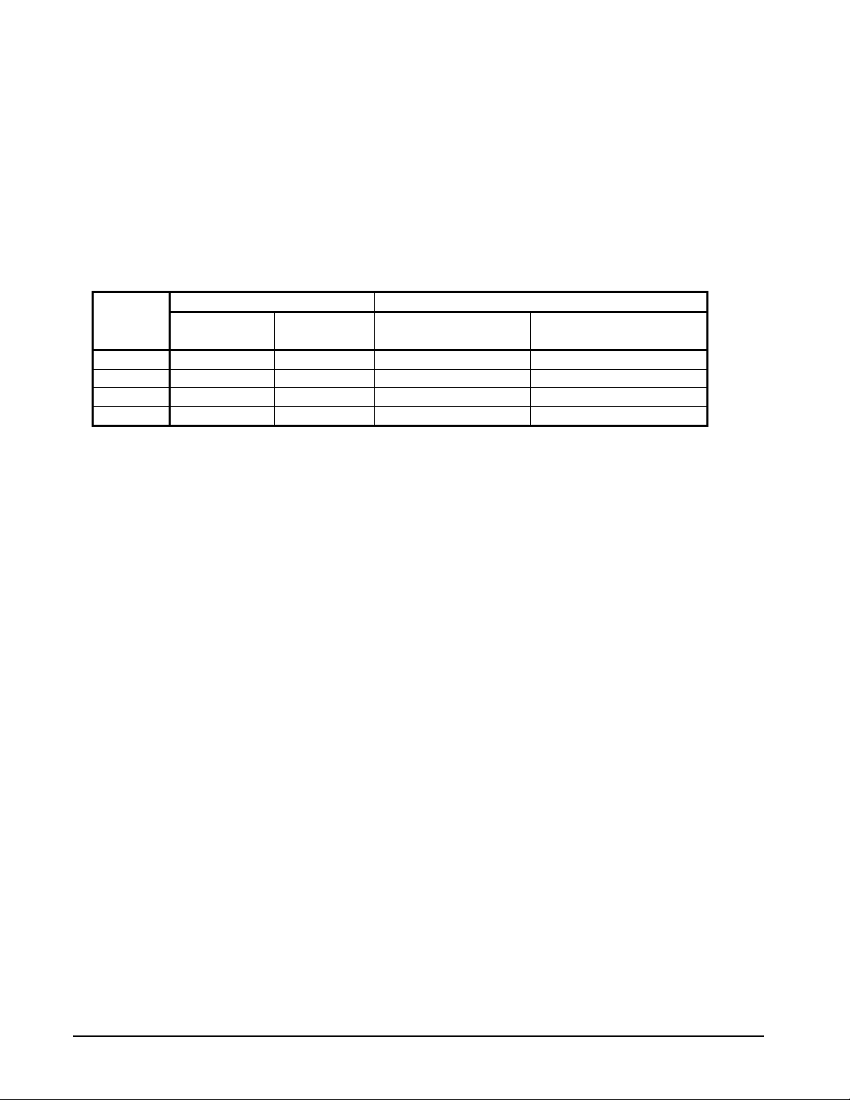
Ambient Air Temperature Limitations
Standard/High Ambient Panels
The AGZ-C units for high ambient operation
(105F to 125F maximum) require the
addition of the High Ambient Control Panel
Option, which includes the addition of a small
fan with a filter in the air intake to cool the
control panel.
Table 1, Panel Ratings
All units with the optional VFD low ambient
fan control automatically include the High
Ambient Control Panel Option. Operation of
the VFD generates a quantity of panel heat best
removed by use of a control panel fan.
Voltage
208-230
240
380-460
575
Standard
Standard Options
Optional
Panel
35 5 120 120
35 5 100 100
35 5 65 65
5 5 25 25
VFD
Water Flow Limitations
The evaporator flow rates and pressure drops
shown on page 9 (and following) are for full
load design purposes in order to m
proper unit control. The maximum flow rate
and pressure drop are based on a 6 degree
temperature drop. Avoid higher flow rates with
resulting lower temperature drops to prevent
potential control problems resulting from very
small control bands and limited start up/shut
off temperature changes.
Variable Speed Pumping
Variable water flow involves changing the
water flow through the evaporator as the load
changes. McQuay chillers are designed for this
duty provided that the rate of change in water
flow is slow and the minimum and maximum
flow rates for the vessel are not exceeded.
The recommended maximum change in water
flow is 10 percent of the change per minute.
aintain
High Short Circuit
Panel (kA)
The minimum flow and pressure drop is based
on a full load evaporator temperature drop of
16 degrees. Evaporator flow rates below the
minimum values can result in laminar flow
causing freeze-up problems, scaling and poor
control. Flow rates above the maximum values
will result in unacceptable pressure drops and
can cause excessive erosion, potentially
leading to failure.
When units are operated with flow rates less
than nominal (see Table 8), the “Evap Delta T”
setpoint m
match the minimum operating flow rate. The
“Delta T” setting should be increased by the
same percentage as the flow reduction is from
the nominal rating in order to prevent short
cycling. This will require reevaluation of
“Cool LWT”, “Startup Delta T”, and “Stop
Delta T” settings as well.
ust be changed proportionally to
High Interrupt Panel w/
Disconnect Swt. (kA)
4 AGZ 030C through 190C OM AGZC-1
Page 5

System Water Volume
T
Considerations
All chilled water systems need adequate time
to recognize a load change, respond to that
load change and stabilize without undesirable
short cycling of the compressors or loss of
control. In air conditioning systems, the
potential for short cycling usually exists when
the building load falls below the minimum
chiller plant capacity or on close-coupled
systems with very small water volumes.
Some of the things the designer should
consider when looking at water volume are the
minimum cooling load, the minimum chiller
plant capacity during the low load period and
the desired cycle time for the compressors.
Assuming that there are no sudden load
changes and that the chiller plant has
reasonable turndown, a rule of thumb of
“gallons of water volume equal to two to three
times the chilled water gpm flow rate” is often
used.
A properly designed storage tank should be
added if the system components do not provide
sufficient water volume.
Glycol Solutions
The use of a glycol/water mixture in the
evaporator to prevent freezing will reduce
system capacity and efficiency, as well as
increase pressure drop. The system capacity,
required glycol solution flow rate, and pressure
drop with glycol may be calculated using the
following formulas and tables.
1. Capacity – Multiply the capacity based on
water by the Capacity correction factor
from Table 2 through Table 5.
2. Flow – Multiply
by the Flow correction factor from Table 2
through Table 5 to determine the increased
evaporator flow due to gly
If the flow is unknown, it can be calculated
from the following equation:
the water evaporator flow
col.
glycolCapacityTons
)(×24
=(gpm) Flow Glycol
TDelta
×
FactorCorrectionFlow
For Metric Applications
– Use the following equation:
(l/s) Flow Glycol
3. Pressure drop -- Multiply the water
pressure drop from page 10 by Pr
essure
Drop correction factor from Table 2
through Table 5. High concentrations of
lene glycol at low temperatures can
propy
cause unacceptably high pressure drops.
4. Power -- Multiply the water system power
by Power correction factor from Table 2 Table 5.
est coolant with a clean, accurate glycol
T
CapacitykW
Delta
18.4
service stations) to determine the freezing
point. Obtain percent glycol from the freezing
point tables below. It is recommended that a
minimum of 25% solution by weight be used
for protection against corrosion or that
additional compatible inhibitors be added.
Concentrations above 35 % do not provide any
additional burst protection and should be
carefully considered before using.
FactorCorrectionFlow
solution hydrometer (similar to that found in
!
WARNING
Do not use an automotive grade antifreeze. Industrial grade glycols must be used. Automotive antifreeze
contains inhibitors which will cause plating on the copper tubes within the chiller evaporator. The type
and handling of glycol used must be consistent with local codes
OM AGZC-1 AGZ 030C through 190C 5
Page 6

Table 2, Ethylene Glycol Factors for Models AGZ 030C to 130C
% E.G.
10
20
30
40
50
Freeze Point
o
F
26 -3.3 0.998 0.998 1.036 1.097
18 -7.8 0.993 0.997 1.060 1.226
7 -13.9 0.987 0.995 1.092 1.369
-7 -21.7 0.980 0.992 1.132 1.557
-28 -33.3 0.973 0.991 1.182 1.791
o
C
Capacity Power Flow PD
Table 3, Propylene Glycol Factors for Models AGZ 030C to 130C
% P.G.
10
20
30
40
50
Freeze Point
o
F
26 -3.3 0.995 0.997 1.016 1.100
19 -7.2 0.987 0.995 1.032 1.211
9 -12.8 0.978 0.992 1.057 1.380
-5 -20.6 0.964 0.987 1.092 1.703
-27 -32.8 0.952 0.983 1.140 2.251
o
C
Capacity Power Flow PD
Table 4, Ethylene Glycol Factors for Models AGZ 140C to 180C
% E.G.
10
20
30
40
50
Freeze Point
o
F
26 -3.3 0.994 0.998 1.038 1.101
18 -7.8 0.982 0.995 1.063 1.224
7 -13.9 0.970 0.992 1.095 1.358
-7 -21.7 0.955 0.987 1.134 1.536
-28 -33.3 0.939 0.983 1.184 1.755
o
C
Capacity Power Flow PD
Table 5, Propylene Glycol Factors for Models AGZ 140C to 180C
% P.G.
10
20
30
40
50
Freeze Point
o
F
26 -3.3 0.988 0.996 1.019 1.097
19 -7.2 0.972 0.992 1.035 1.201
9 -12.8 0.951 0.987 1.059 1.351
-5 -20.6 0.926 0.979 1.095 1.598
-27 -32.8 0.906 0.974 1.142 2.039
o
C
Capacity Power Flow PD
Altitude Correction Factors
Performance tables are based at sea level.
Elevations other than sea level affect the
performance of the unit. The decreased air
density will reduce condenser capacity
consequently reducing the unit's performance.
For performance at elevations other than sea
level, refer to Table 6 and Table 7.
Evaporator Temperature Drop Factors
Performance tables are based on a 10°F (5°C)
temperature drop through the evaporator.
Adjustment factors for applications with
temperature ranges from 6°F to 16°F (3.3°C to
8.9°C) are in Table 6 and Table 7.
emperature drops outside this 6°F to 16°F
T
(3.3°C to 8.9°C) range can affect the control
system's capability to maintain acceptable
control and are not recommended.
The maximum water temperature that can be
circulated through the evaporator in a nonoperating mode is 100°F (37.8°C).
6 AGZ 030C through 190C OM AGZC-1
Page 7

Fouling Factor
Performance tables are based on water with a
fouling factor of:
22
per ARI 550/590-98.
As fouling is increased, performance decreases.
Foreign m
system will adversely affect the heat
transfer capability of the evaporator
kWCmorBTUFhrft
and reduce the water flow. Maintain
and could increase the pressure drop
)/0176.0(/0001.0
proper water treatment to provide
optimum unit operation.
atter in the chilled water
For performance at other than 0.0001 (0.0176)
fouling factor, refer to Table 6 or Table 7.
Table 6, Capacity and Power Derates, Models AGZ 030C to 130C
Fouling Factor
Altitude
Sea
Level
2000 feet
4000 feet
6000 feet
Chilled Water Delta T
°F °C Cap. Power Cap. Power Cap. Power Cap. Power
6 3.3 0.978 0.993 0.975 0.991 0.963 0.987 0.940 0.980
8 4.4 0.989 0.996 0.986 0.994 0.973 0.990 0.950 0.983
10 5.6 1.000 1.000 0.996 0.999 0.984 0.994 0.961 0.987
12 6.7 1.009 1.003 1.005 1.001 0.993 0.997 0.969 0.990
14 7.7 1.018 1.004 1.014 1.003 1.002 0.999 0.978 0.991
16 8.9 1.025 1.007 1.021 1.006 1.009 1.001 0.985 0.994
6 3.3 0.977 1.001 0.973 1.000 0.961 0.996 0.938 0.989
8 4.4 0.987 1.006 0.984 1.004 0.971 1.000 0.948 0.993
10 5.6 0.998 1.009 0.995 1.007 0.982 1.003 0.959 0.996
12 6.7 1.007 1.011 1.004 1.010 0.991 1.006 0.967 0.998
14 7.7 1.014 1.014 1.011 1.013 0.998 1.009 0.974 1.001
16 8.9 1.022 1.016 1.018 1.014 1.005 1.010 0.981 1.003
6 3.3 0.973 1.011 0.970 1.010 0.957 1.006 0.935 0.998
8 4.4 0.984 1.014 0.980 1.013 0.968 1.009 0.945 1.001
10 5.6 0.995 1.019 0.991 1.017 0.979 1.013 0.955 1.005
12 6.7 1.004 1.021 1.000 1.020 0.987 1.016 0.964 1.008
14 7.7 1.011 1.024 1.007 1.023 0.994 1.018 0.971 1.011
16 8.9 1.018 1.027 1.014 1.026 1.002 1.021 0.978 1.014
6 3.3 0.969 1.021 0.966 1.020 0.954 1.016 0.931 1.008
8 4.4 0.980 1.026 0.977 1.024 0.964 1.020 0.942 1.013
10 5.6 0.989 1.029 0.986 1.027 0.973 1.023 0.950 1.015
12 6.7 0.998 1.033 0.995 1.031 0.982 1.027 0.959 1.020
14 7.7 1.007 1.036 1.004 1.034 0.991 1.030 0.967 1.022
16 8.9 1.014 1.037 1.011 1.036 0.998 1.031 0.974 1.024
0.0001 (0.0176) 0.00025 (0.044) 0.00075 (0.132) 0.00175 (0.308)
OM AGZC-1 AGZ 030C through 190C 7
Page 8

Table 7, Capacity and Power Derates, Models AGZ 075 to 130
Chilled Water
Altitude
Sea
Level
2000 feet
4000 feet
6000 feet
8000 feet
Delta T
°F °C Cap. Power Cap. Power Cap. Power Cap. Power
6 3.3 0.990 0.997 0.976 0.994 0.937 0.983 0.868 0.964
8 4.4 0.994 0.998 0.981 0.995 0.942 0.984 0.872 0.965
10 5.6 1.000 1.000 0.987 0.996 0.947 0.986 0.877 0.967
12 6.7 1.005 1.001 0.991 0.997 0.951 0.986 0.881 0.968
14 7.7 1.009 1.002 0.995 0.998 0.955 0.987 0.884 0.968
16 8.9 1.013 1.004 1.000 1.000 0.960 0.989 0.889 0.970
6 3.3 0.987 1.005 0.974 1.002 0.934 0.991 0.865 0.972
8 4.4 0.992 1.006 0.979 1.003 0.940 0.992 0.870 0.973
10 5.6 0.997 1.008 0.984 1.004 0.944 0.994 0.875 0.975
12 6.7 1.002 1.009 0.989 1.005 0.949 0.994 0.879 0.975
14 7.7 1.007 1.011 0.993 1.007 0.953 0.996 0.883 0.977
16 8.9 1.011 1.012 0.998 1.008 0.958 0.997 0.887 0.978
6 3.3 0.985 1.014 0.972 1.010 0.933 0.999 0.864 0.980
8 4.4 0.991 1.015 0.977 1.012 0.938 1.001 0.869 0.981
10 5.6 0.995 1.016 0.982 1.013 0.943 1.002 0.873 0.982
12 6.7 1.000 1.018 0.987 1.014 0.947 1.003 0.877 0.984
14 6.8 1.005 1.019 0.991 1.015 0.951 1.004 0.881 0.985
16 8.9 1.009 1.021 0.995 1.017 0.955 1.006 0.884 0.987
6 3.3 0.982 1.023 0.969 1.020 0.930 1.009 0.861 0.989
8 4.4 0.988 1.025 0.975 1.022 0.935 1.010 0.866 0.991
10 5.6 0.992 1.026 0.979 1.022 0.940 1.011 0.870 0.992
12 6.7 0.997 1.028 0.984 1.024 0.944 1.013 0.875 0.994
14 7.7 1.002 1.029 0.989 1.025 0.949 1.014 0.879 0.995
16 8.9 1.006 1.031 0.992 1.027 0.952 1.016 0.882 0.996
6 3.3 0.979 1.034 0.966 1.031 0.927 1.019 0.859 1.000
8 4.4 0.984 1.036 0.971 1.032 0.932 1.021 0.863 1.002
10 5.6 0.990 1.037 0.976 1.033 0.937 1.022 0.868 1.002
12 6.7 0.993 1.039 0.980 1.035 0.941 1.024 0.871 1.004
14 7.7 0.998 1.041 0.985 1.037 0.945 1.026 0.875 1.006
16 8.9 1.003 1.041 0.990 1.038 0.950 1.026 0.879 1.007
0.0001 (0.0176) 0.00025 (0.044) 0.00075 (0.132) 0.00175 (0.308)
Evaporator Freeze Protection
Evaporator freeze-up can be a concern in the
application of air-cooled water chillers. To
protect against freeze-up, insulation and an
electric heater cable are furnished with the unit.
This protects the evaporator down to -20°F (29°C) ambient air temperature. Although the
evaporator is equipped with freeze protection,
it does not protect water piping external to the
unit or the evaporator itself if there is a power
failure or heater cable burnout. Consider the
Fouling Factor
vent connections are provided on the
evaporator to ease draining.
2. Add a glycol solution to the chilled water
system to provide freeze protection.
Freeze point should be approximately ten
degrees below minimum design ambient
temperature.
3. The addition of thermostatically controlled
heat and insulation to exposed piping.
4. Continuous circulation of water through
the chilled water piping and evaporator.
following recommendations for additional
protection.
1. If the unit will not be operated during the
winter, drain evaporator and chilled water
piping and flush with glycol. Drain and
The evaporator heater cable is factory wired to
the 115-volt circuit in the control box. This
power should be supplied from a separate
source, but it can be supplied from the control
circuit. Operation of the heater cable is
8 AGZ 030C through 190C OM AGZC-1
Page 9

automatic through the ambient sensing
thermostat that energizes the evaporator heater
cable for protection against freeze-up. Unless
the evaporator is drained in the winter, the
disconnect switch to the evaporator heater must
not be open.
Operating/Standby Limits
Maximum standby ambient air
temperature, 130F (55C)
Maximum operating ambient air
temperature 105 F (40.6 C)
Leaving chilled water temperature, 40F
to 60F (4.4C to 15.6C)
Leaving chilled fluid temperatures (with
anti-freeze), 15F to 60F (-9.4C to
15.6C)
Design chilled water Delta-T range, 6
degrees F to 16 degrees F (3.3 C to
8.9C)
Part load minimum flow for variable
flow systems, varies with unit size, see
Table 8 below.
Minimum operating ambient
temperature (standard), 35F (2C)
Minimum operating ambient
temperature (with optional low-ambient
control), 0F (-18C)
Pressure Drop Curves
Evaporator pressure drop curves on the
following page. They apply to either packaged
or remote evaporator applications. Figure 1,
Evaporator Pressure Drops. See following page
for curve cross-reference on the next page
contains the evaporator reference letter and the
nimum and maximum flows allowed for
mi
each unit.
Maxim
temperature, 76F (24C)
Maximum non-operating inlet fluid
temperature, 100F (38 C).
Occasionally the same evaporator is used on
multiple units resulting in overlapping lines.
The minimum and maximum flows for a given
unit will be at the point where the unit
reference number appears.
um operating inlet fluid
OM AGZC-1 AGZ 030C through 190C 9
Page 10

Figure 1, Evaporator Pressure Drops. See following page for curve cross-reference
See following page for curve cross-reference and min/max flow rates.
Q
A
B
C
F
E
D
J
M
N
K
L
O
P
I
G
H
10 AGZ 030C through 190C OM AGZC-1
Page 11

Table 8, Curve Cross-Reference, Min/Nominal/Max Flows
Curve
AGZ
Unit
Ref.
Model
A 030C ACH130-90DQ 47.3 5.1 3.0 15.4 75.6 12.0 4.8 35.9 126.0 30.1 8.0 90.0 31.5
B 035C ACH130-102DQ 51.2 4.8 3.2 14.2 81.8 11.1 5.2 33.2 136.4 27.9 8.6 83.3 34.1
C 040C ACH130-118DQ 55.7 4.3 3.5 12.8 89.0 10.0 5.6 29.9 148.4 25.1 9.4 75.0 37.1
D 045C ACH130-138DQ 63.2 4.5 4.0 13.5 101.0 10.5 6.4 31.4 168.4 26.3 10.6 78.7 42.1
E 050C ACH130-158DQ 71.4 5.1 4.5 15.1 114.2 11.8 7.2 35.3 190.4 29.6 12.0 88.5 47.6
F 055C ACH130-178DQ 77.1 5.1 4.9 15.3 123.4 11.9 7.8 35.7 205.6 30.0 13.0 89.6 51.4
G 060C ACH250-110DQ 82.7 2.6 5.2 7.8 132.2 6.1 8.3 18.1 220.4 15.2 13.9 45.4 55.1
H 065C ACH250-122DQ 85.7 2.4 5.4 7.2 137.0 5.6 8.6 16.8 228.4 14.1 14.4 42.0 57.1
I 070C ACH250-122DQ 93.4 2.9 5.9 8.6 149.5 6.8 9.4 20.2 249.1 16.8 15.8 50.5 62.3
J 075C ACH350-118DQ 107.4 4.3 6.8 13.0 171.8 10.1 10.8 30.3 286.4 25.4 18.1 75.9 71.6
K 080C ACH350-126DQ 119.3 4.4 7.5 13.2 190.8 10.3 12.0 30.7 318.0 25.7 20.1 76.9 79.5
L 090C ACH350-142DQ 129.4 4.3 8.1 13.0 207.1 10.1 13.0 30.1 345.2 25.2 21.8 75.5 86.3
M 100C ACH350-150DQ 146.7 4.9 9.2 14.7 234.7 11.4 14.8 34.3 391.2 28.7 24.7 85.9 97.8
N 110C ACH350-162DQ 156.3 4.8 9.9 14.3 250.1 11.1 15.8 33.3 416.8 27.9 26.3 83.5 104.2
O 125C ACH350-182DQ 171.5 4.6 10.8 13.8 274.3 10.8 17.3 32.1 457.2 27.0 28.8 80.6 114.3
P 130C ACH350-210DQ 187.1 4.2 11.8 12.5 299.3 9.8 18.9 29.1 498.8 24.5 31.5 73.1 124.7
Q 140C EV34191111/9 200.6 5.0 12.7 15.0 320.9 11.8 20.2 33.1 534.8 29.5 33.7 88.0 133.7
Q 160C EV34191111/9 227.3 6.3 14.3 18.9 363.6 14.7 22.9 41.5 606.0 36.8 38.2 110.2 151.5
Q 180C EV34191111/9 254.0 7.7 16.0 22.9 406.3 18.0 25.6 50.8 677.2 45.1 42.7 134.6 169.3
Q 190C EV34191212/7 270.2 9.4 17.0 28.0 432.2 22.0 27.2 62.1 720.3 55.1 45.4 164.4 180.1
Evap
Model
Minimum Flow Rate Nominal Flow Rate Maximum Flow Rate
Inch-Pound S.I. Inch-Pound S.I. Inch-Pound S.I.
gpm
DP
ft.
lps
DP
kpa
gpm
DP
ft.
lps
DP
kpa
gpm
DP
ft.
lps
DP
kpa
Nom
Tons
NOTE: Evaporators beginning with ACH are brazed-plate; those beginning with EV are shell-and-tube.
OM AGZC-1 AGZ 030C through 190C 11
Page 12

Figure 2, AGZ030C – AGZ 180C, Typical Field Wiring
3 PHASE
POWER
DISCONNECT
(BY OTHERS)
UNIT MAIN
TERMINAL BLOCK
GND LUG
TO COMPRESSOR(S)
AND FAN MOTORS
NOTE: ALL FIELD WIRING TO BE
INSTALLED AS NEC CLASS 1
WIRING SYSTEM WITH CONDUCTOR
RATED 600 VOLTS
FIELD SUPPLIED
ALARM BELL
REMOTE STOP SWITCH
(BY OTHERS)
ICE MODE SWITCH
(BY OTHERS)
OPTION
CONTROL POWER
OPTION
CHW FLOW SWITCH
---MANDATORY–(BY OTHERS)
N
120VAC
FACTORY SUPPLIED ALARM
FIELD WIRED
ALARM BELL RELAY
TIME
CLOCK
FUSED CONTROL
CIRCUIT TRANSFORMER
DISCONNECT
(BY OTHERS)
10A
FUSE
(BY OTHERS)
CHW PUMP RELAY
120 VAC 1.0 AMP MAX
OFF
AUTO
ON
MANUAL
OFF
AUTO
ON
MANUAL
(BY OTHERS)
120 VAC
CONTROLLER
TB1
TB2
TB1-20
1
2
35
33
34
CONTROL
CIRCUIT
FUSE
120 VAC
N
120 VAC
32
GND
IF REMOTE STOP
585
CONTROL IS USED,
REMOVE LEAD 585
FROM TERM. 52
TO 72.
BELL
12
ALARM BELL OPTION
ALARM BELL
RELAY
COM NO
52
72
43
83
54
74
NOR. OPEN PUM P AUX.
CONTACTS (OPTIONAL)
44
61
4-20MA FOR
EVAP. WATER RESET
(BY OTHERS)
4-20MA FOR
DEMAND LIMIT
(BY OTHERS)
DWG. 330423101 REV.0A
+
-
+
-
LESS EVAPORATOR ONLY
LIQUID LINE #1 SOLENOID
24 VAC 1.5 AMP MAX
LIQUID LINE #2 SOLENOID
24 VAC 1.5 AMP MAX
68
69
70
71
GND
91
93
92
93
24 VAC
N
24 VAC
N
12 AGZ 030C through 190C OM AGZC-1
Page 13

MicroTech II Controller
Software Version AGZDU0102B
Controller Section Table of Contents
Overview........................................................................................................................14
General Description .......................................................................................................14
Setpoints
namic Defaults ..........................................................................................................18
Dy
Security
Control Functions
Unit Enable
Unit Mode Selection
Unit S
Power Up S
Ice Mode S
Low Am
Evaporator
Leaving W
Maxim
Unit Capacity
Circuit Capacity
Low Am
Com
Manual Com
Norm
Rapid Circuit Shutdown
cle Timers..................................................................................................................28
Cy
Liquid Line Solenoid
Hot Gas By
EXV
Condenser Fan Control
........................................................................................................................16
..........................................................................................................................19
..........................................................................................................19
....................................................................................................................20
......................................................................................................21
tate .......................................................................................................................22
tart Delay ....................................................................................................23
tart Delay .....................................................................................................23
bient Lockout ...................................................................................................23
Water Pump State........................................................................................24
ater Temperature (LWT) Reset .....................................................................24
um LWT Rate .....................................................................................................24
Overrides ................................................................................................24
Overrides – Limits of Operation.........................................................25
bient Starts .......................................................................................................26
pressor Sequencing.................................................................................................26
pressor Control..........................................................................................27
al Circuit Shutdown..............................................................................................27
.................................................................................................28
.....................................................................................................28
pass Solenoid ..............................................................................................28
Control..................................................................................................................28
..................................................................................................29
Alarms and Events
top Alarms............................................................................................................31
Unit S
Circuit S
Circuit Events
Clearing
OM AGZC-1 AGZ 030C through 190C 13
top Alarms........................................................................................................31
Alarms.............................................................................................................34
.......................................................................................................31
................................................................................................................33
Page 14

Overview
The MicroTech II® controller’s state-of-the-art
design not only permits the chiller to run more
efficiently, but also can simplify
troubleshooting if a system failure occurs.
Every MicroTech II controller is programmed
and tested prior to shipment to facilitate startup.
Operator-friendly
The MicroTech II controller menu structure is
separated into three distinct categories that
provide the operator or service technician with
a full description of 1) current unit status, 2)
control parameters, and 3) alarms. Security
protection prevents unauthorized changing of
the setpoints and control parameters.
MicroTech II control continuously performs
self-diagnostic checks, monitoring system
temperatures, pressures and protection devices,
and will automatically shut down a compressor
or the entire unit should a fault occur. The
cause of the shutdown will be retained in
memory and can be easily displayed in plain
English for operator review. The MicroTech II
chiller controller will also retain and display
the date/time the fault occurred. In addition to
displaying alarm diagnostics, the MicroTech II
chiller controller also provides the operator
with a warning of limit (pre-alarm) conditions.
General Description
AGZ-C Inputs/Outputs
Table 9, Analog Inputs
# Description Type Signal Source Expected Range
1 Evaporator Refrigerant Pressure #1 C1 0.1 to 0.9 VDC
2 Evaporator Refrigerant Pressure #2 C2 0.1 to 0.9 VDC
3 Condenser Refrigerant Pressure #1 C1 0.1 to 0.9 VDC
4 Leaving Evaporator Water Temperature UT
5 Outside Ambient Temperature UT
6 Condenser Refrigerant Pressure #2 C2 0.1 to 0.9 VDC
7 Reset of Leaving Water Temperature UT 4-20 mA Current 4-20 mA
8 Demand Limit UT 4-20 mA Current 4-20 mA
9 Compressor Suction Temperature #1 C1
10 Compressor Suction Temperature #2 C2
NOTES:
1. C1 = Refrigerant Circuit #1, C2 = Refrigerant Circuit #2, UT = Unit
NTC Thermister
(10k@
NTC Thermister
(10k@
NTC Thermister
(10k@
NTC Thermister
(10k@
77F)
77F)
77F)
77F)
0 to 132 psi
0 to 132 psi
3.6 to 410 psi
-58 to 212°F
-58 to 212°F
3.6 to 410 psi
-58 to 212°F
-58 to 212°F
Table 10, Analog Outputs
# Description Output Signal Range
1 Fan #1 VFD 0 to 10 VDC 0 to 100% (1000 steps resolution)
2 Fan #2 VFD 0 to 10 VDC 0 to 100% (1000 steps resolution)
3 EXV #1 0 to 10 VDC 0 to 100% (1000 steps resolution)
4 EXV #2 0 to 10 VDC 0 to 100% (1000 steps resolution)
5 Open - 6 Open - -
14 AGZ 030C through 190C OM AGZC-1
 Loading...