

Page 1
Installation, Operation and Maintenance Manual
IOMM AGZ1
Air-Cooled Scroll Compressor Water Chillers
AGZ 010A – AGZ 034A
10 to 34 Tons, 35 to 120 kW
R-22, 60 Hertz
Group:
Part Number
Effective:
Supersedes:
Chiller
October 2001
: 330262001
New
Page 2
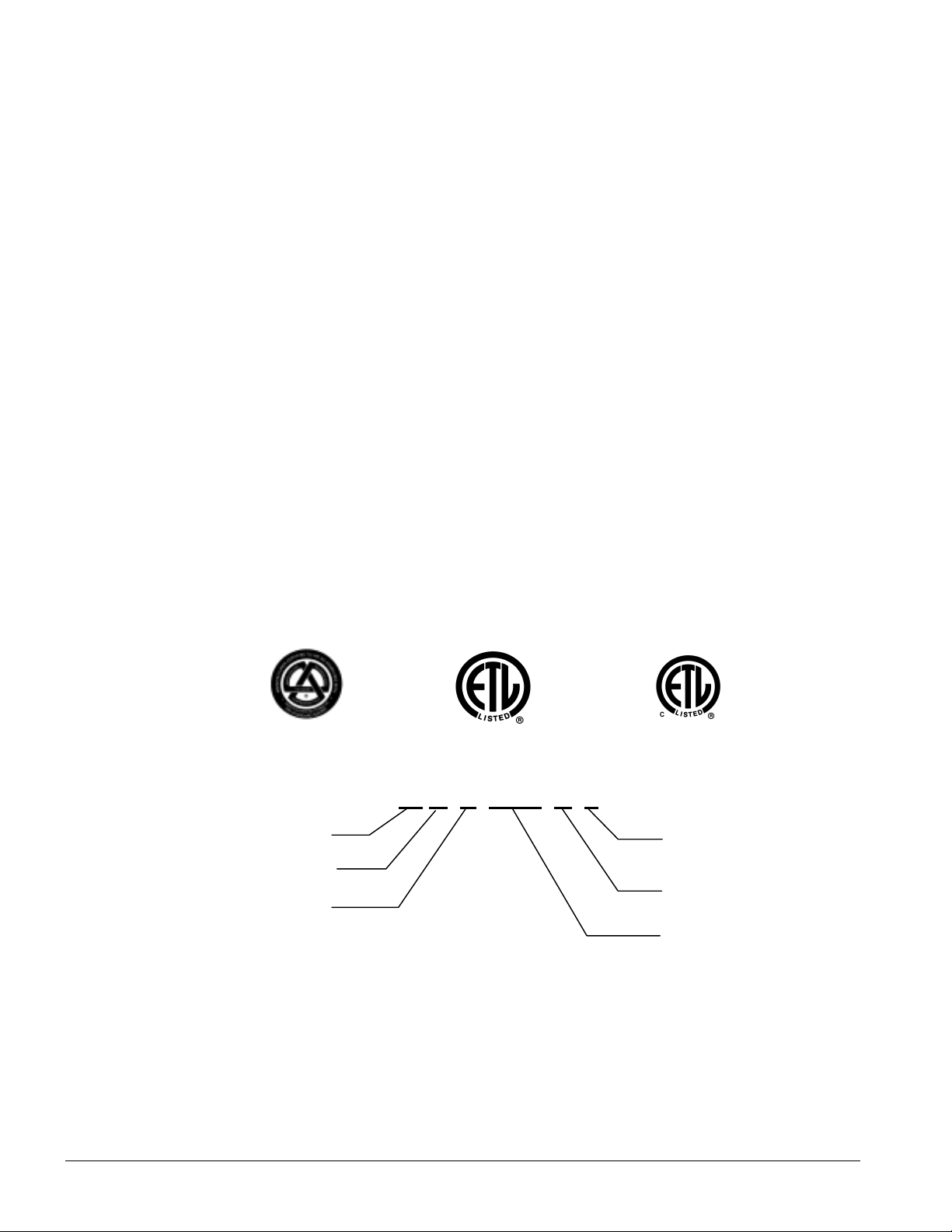
Table of Contents
N
Introduction........................................3
General Description......................................... 3
Inspection ........................................................ 3
Installation....................................................... 3
Handling.......................................................... 3
Location........................................................... 4
Service Access................................................. 4
Vibration Isolators........................................... 6
Chilled Water System...................................... 6
Water Connections........................................... 9
Refrigerant Charge........................................... 9
Unit Component Location............................... 9
Glycol Solutions.............................................. 9
Evaporator Water Flow and Pressure Drop..... 9
Control Layout and Operation.......11
Control Center................................................11
Start-up and Shutdown...................11
Pre Start-up.....................................................11
Start-up...........................................................11
Sequence of Operation................................... 12
Physical Data....................................13
Electrical Data................................. 15
Field Wiring................................................... 15
Dimensional Data............................ 20
System Maintenance....................... 21
General...........................................................21
Lubrication.....................................................21
Electrical Terminals.......................................21
Condensers.....................................................21
Refrigerant Sightglass.................................... 21
Standard MicroTech II Controller 22
Table of Contents........................................... 22
Overview........................................................23
General Description....................................... 23
Using the Controller.......................................30
Service.............................................. 42
Thermostatic Expansion Valve.......................42
Filter-Driers...................................................42
Liquid Line Solenoid..................................... 42
Optional Controls...........................................43
Troubleshooting Chart ...................................45
MODEL CODE
A G
Air-Cooled
Global Series
Scroll Compressor
"McQuay" is a registered trademark of McQuay International
"Illustrations and data cover the McQuay International products at the time of publication and we reserve the right to make changes in design and
2
construction at anytime without notice"
AGZ 010A through 034A IOMM AGZ1
Z XXX A S
2001 McQuay International
S=Packaged Evaporator
M=Remote Evaporator
Vintage
ominal To ns
Page 3
Introduction
General Description
McQuay air-cooled water chillers are complete, self-contained automatic refrigerating units. Every
unit is completely assembled, factory wired, charged, and tested. Each unit consists of air-cooled
condensers, Copeland Compliant Scroll hermetic compressor, brazed plate-to-plate evaporator, and
complete refrigerant piping. Liquid line components include sight-glass/moisture indicator, solenoid
valve, and thermal expansion valve. Other features include a compressor heater, and evaporator
heater for chilled water freeze protection.
The electrical control center includes all equipment protection and operating controls necessary for
automatic operation. Condenser fan motors are three-phase (except single-phase on No. 1 fan with
SpeedTrol option) and started by their own contactors and have inherent overload protection. The
compressor has solid-state motor protection for inherent thermal overload protection except Model
AGZ 010 that has internal line breakage.
Inspection
Check all items carefully against the bill of lading. Inspect all units for damage upon arrival. Report
shipping damage and file a claim with the carrier. Check the unit nameplate before unloading to be
sure it agrees with the power supply available. Units are shipped FOB factory and McQuay is not
responsible for physical damage after unit leaves the factory.
Note:
Unit shipping and operating weights are listed on pages 13 and 14.
Installation
Note:
Installation is to be perform ed by qualified personnel who are familiar with local codes
and regulations, especially concerning refrigerant release to the atmosphere.
WARNING
Sharp edges and coil surfaces are a potential hazard. Avoid contact with them.
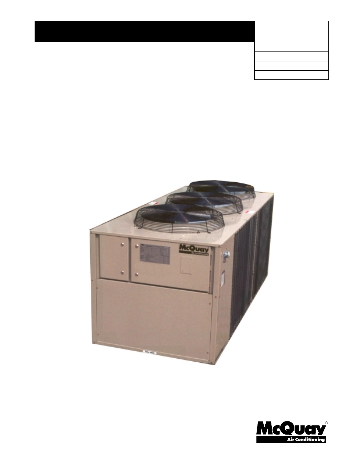
Handling
Be careful to avo id r ough hand ling o f the unit. Do not push or p ull t he uni t fr om anything othe r t han
the base. Block the pushing vehicle away from the unit to prevent damage to the sheet-metal cabinet
and end frame (see Figure 1).
To lift the unit, lifting slots are provided in the base of the unit. Arrange spreader bars and cables to
prevent damage to the condenser coils or cabinet (see Figure 2).
IOMM AGZ1 AGZ 010A through 034A
3
Page 4
Figure 1, Suggested Pushing Arrange ment
Blocking required
across full width
Figure 2, Suggested Lifting Arrangement
Location
Unit Placement
AGZ units are for outdoor applications and can be mounted on a roof or at ground level. Set units on
a solid and level foundation. For roof-mounted applications, install the unit on a steel channel or Ibeam frame to support the unit above the roof. For ground level applications, install the unit on a
substantial base that will not settle. A one-piece concrete slab with footings extended below the frost
line is recommended. Be sure the foundation is level (within 1/2” [13 mm] over its length and width).
The foundation must support the operating weights listed in the Physical Data Tables on pages 13 and
14.
Since its operation is affected by wind, the unit should be located so that its length is parallel with the
prevailing wind. If this is not practical, use field fabricated wind deflectors.
Service Access
Each end of the unit must be accessible after installation for periodic service. Compressors, filterdriers, and liquid line solenoid valve are accessible from the end of the unit. High-pressure, lowpressure, and motor protector controls are on the compressor. Most operational, safety and starting
controls are located in the unit control box.
The fan deck with the condenser fans and motors can be removed from the top of the unit.
4
AGZ 010A through 034A IOMM AGZ1
Page 5
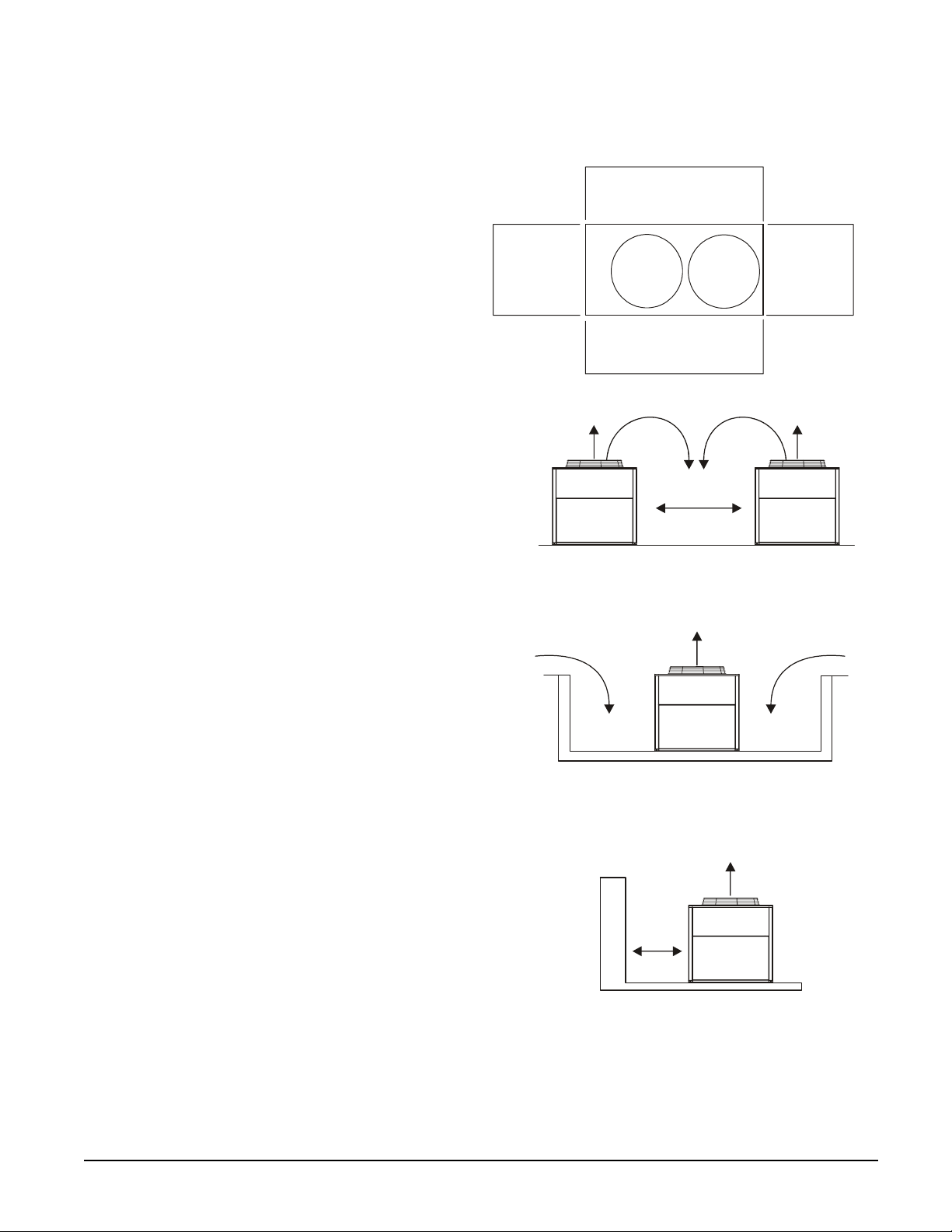
Clearances
The flow of air to and from the condenser
coil must not be limited. Restricting
airflow or allowing air recirculation will
result in a decrease in unit performance
and efficiency. There must be no
obstruction above the unit that would
deflect discharge air downward where it
could be recirculated back to the inlet of
the condenser coil. The condenser fans are
propeller type and will not operate with
ductwork on the fan outlet.
Install the unit with enough si de clearance
for air entrance to the coil and for
servicing. Provide service access to the
evaporator, compressors, electrical control
panel and piping components as shown in
Figure 3. Do not block access to the unit
with piping or conduit.
Do not allow debris to accumulate near the
unit. Air movement may draw debris into
the condenser coil causing air starvation.
Give special consideration to low ambient
operation where snow can accumulate.
Keep condenser coils and fan discharge
free of snow or other obstructions to permit
adequate airflow.
Figure 3, Clearance requirements
4 Ft. (1220mm)
Clearance for Air Inlet
4 Ft.
(1220mm)
Clearance for
Service Access
4 Ft. (1220mm)
Clearance for Air Inlet
The recommended minimum side clearance between two units
is 8 feet (2440mm).
4 Ft.
(1220mm)
Clearance for
Service Access
Sound Isolation
The low sound levels of the AGZ chiller are
suitable for most applications. When
additional sound reduction is necessary,
locate the unit away from sound sensitive
areas. Avoid locations beneath windows or
between structures where normal operating
sounds may be objectionable. Reduce
structurally transmitted sound by isolating
water lines, electrical conduit and the unit
itself. Use wall sleeves and rubber isolated
piping hangers to reduce transmission of
water or pump noise into occupied spaces.
Use flexible electrical conduit to isolate
sound through electrical conduit. Spring
isolators are effective in reducing the low
amplitude sound generated by the Discus
semi-hermetic compressors and for unit
isolation in sound-sensitive areas.
The unit must not be installed in a pit or enclosure that is
deeper or taller than the height of the unit unless extra space
is provided. The minimum clearance on each side of the
unit is 6 feet (1828mm) when installed in a pit. The pit cannot
be deeper than the unit.
The minimum clearance to a side wall or building taller than
the unit height is 6 feet (1828mm) provided no solid wall
above 6 feet (1828mm) tall is closer than 12 feet (3658mm)
to the opposite side of the unit.
IOMM AGZ1 AGZ 010A through 034A
5
Page 6
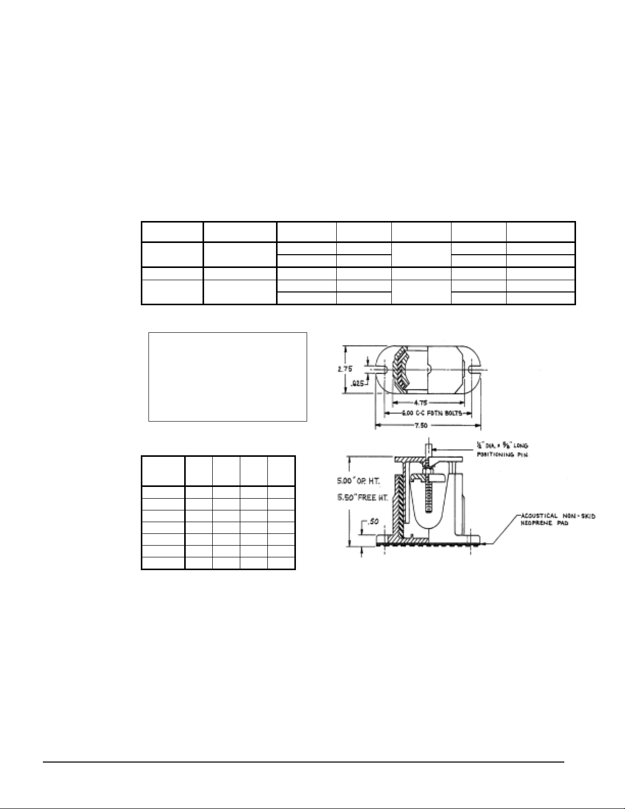
Vibration Isolators
Vibration isolators are recommended for all roof-mounted installations or wherever vibration
transmission is a consideration. The isolators can be purchased from McQuay by the part numbers
shown in the table.
The unit should be initially on shims or blocks at the listed free height. When all piping, wiring,
flushing, charging, etc. is completed, the springs are adjusted upward to loosen the blocks or shims
that are then removed.
A rubber anti-skid pad is part of the isolator. Installation of spring isolators requires flexible piping
connections and at least three feet of flexible conduit to avoid straining the piping and transmitting
vibration and noise.
Table 1, Recommended Vibration Isolators
AGZ UNIT
010A – 034A Rubber-in-shear
010A – 017A Spring Isolators 047792726 4 350014835 All CP-1-26
020A – 034A Spring Isolators
Note: See dimension drawing for location of isolators
ISOLATOR
TYPE
ISOLATOR
PART NO.
021639703 2 LF, RF RP-3 Green
021639701 2
047792726 2 LF, RF CP-1-27
047792727 2
NUMBER
REQUIRED
KIT of FOUR
PART NO.
350014857
350014839
LOCATION
LB, RB RP-3 Red
LB, RB CP-1-26
ISOLATOR
DESCRIPTION
RBI
LBI
RFI
Control
Panel
LFI
Corner Weights
AGZ
Unit
Model
010A 261 367 159 223
013A 372 526 184 260
017A 402 568 200 282
020A 484 621 226 291
025A 499 646 232 301
029A 621 647 326 339
034A 678 784 334 386
RF LF RB LB
Chilled Water System
Water Piping
Local authorities can supply the installer with the proper building and safety codes required for safe
and proper installation.
Install piping with minimum bends and changes in elevation to minimize pressure drop. Consider the
following when installing water piping:
1. Vibration eliminators to reduce vibration and noise transmission to the building.
2. Shutoff valves to isolate the unit from the piping system during unit servicing.
3. Manual or automatic air vent valves at the high points of the system. Install drains at the lowest
points in the system.
6
AGZ 010A through 034A IOMM AGZ1
Page 7
4. A means of maintaining adequat e system water pressure (expansi on tank or regulating valve).
Ai
5. Temperature and pressure indicators located at the unit to aid in unit servicing. Pressure gauge
taps must be installed in the chilled water inlet and outlet piping or as shown in Figure 4.
6. A strainer or other means of removing foreign matter from the water before it enters the pump.
Place the strainer far enough upstream to prevent cavitation at the p ump inlet (consult p ump
manufacturer for recommendations). The use of a strainer will prolong pump life and keep
system performance up.
7. A 40-mesh strainer is required in the water line just before the inlet of the evaporator. This will
help prevent foreign material from entering and decreasing the performance of the evaporator.
CAUTION
If separate disconnect is us ed for the 110V supply to the evaporator heating cable, mark the
disconnect clearly to ensure disconnect is not acc identally shut off during c old seas ons . This
could cause a failure of the evaporator.
8. The brazed plate evaporator has a thermostat and heating cable to prevent freeze-up down to
-20°F (-29°C). It is suggested that the heati ng cable be wired to a separate 110V supp ly circuit.
As shipped from the factory, the heating cable is wired to the control circuit. Protect all water
piping to the unit from freezing.
9. If the unit is used as a replacement chiller on a previously existing piping system, flush the
system thoroughly before unit installation. Regular water analysis and chemical water treatment
on the evaporator is recommended immediately at equipment start-up.
10. When glycol is added to the water system for freeze protection, the refrigerant suction pressure
will be lower, cooling performance less, and water side pressure drop greater. If the percentage
of glycol is high, or if propylene is used instead of ethylene glycol, the added pressure drop and
loss of performance could be substantial. Reset the freezestat and low leaving water alarm
temperatures. The freezestat is factory set to default at 38°F (3.3°C). Reset the freezestat setting
to approximately 4 to 5 degrees F (2.3 to 2.8 degrees C) below the leaving chilled water setpoint
temperature. See the section titled “Glycol Solutions” on page 9 for additional information
concerning glycol .
11. Perform a preliminary leak check before insulating the piping and filling the system.
12. Piping insulation should include a vapor barrier to prevent condensation and possible damage to
the building structure.
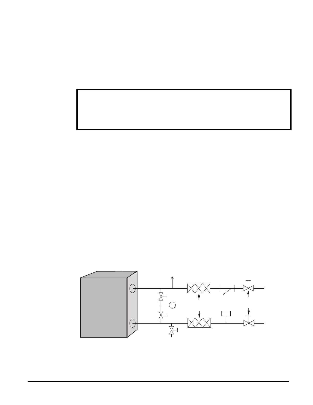
Figure 4, Typical Field Evaporator Water Piping
r
Vent
Inlet
P
Outlet
Drain
NOTES
:
1. Chilled water piping within the unit enclosure must be insulated in the field.
2. Piping should be supported independently of the unit and be installed per local codes.
IOMM AGZ1 AGZ 010A through 034A
Vibration
Eliminators
Strainer
Isolation
Valves
Flow
Switch
7
Page 8
System Volume
It is important to have adequate water volume in the system to provide an opportunity for the chiller
to sense a load change, adjust to the change and stabilize. As the expected load change becomes
more rapid, a greater water volume is needed. The system water volume is the total amount of water
in the evaporator, air handling products and associated piping. If the water volume is too low,
operational problems can occur, including rapid compressor cycling, rapid loading and unloading of
compressors, erratic refrigerant flow in the chiller, improper motor cooling, shortened equipment life
and other undesirable occurrences.
For normal comfort cooling applications, where the cooling load changes relatively slowly, we
recommend a minimum system volume of five minutes times the flow rate (GPM). For example, if
the design chiller flow rate is 120 GPM, we recommend a minimum system volume of 600 gallons
(120 GPM x 5 minutes).
Since there are many other factors that can influence performance, systems may successfully operate
below these suggestions. However, as the water volume decreases below these suggestions, the
possibility of problems increases.
Variable Chilled Water flow
Variab le chilled water flow systems are not recommended for this class of equipment due to limited
unloading capability.
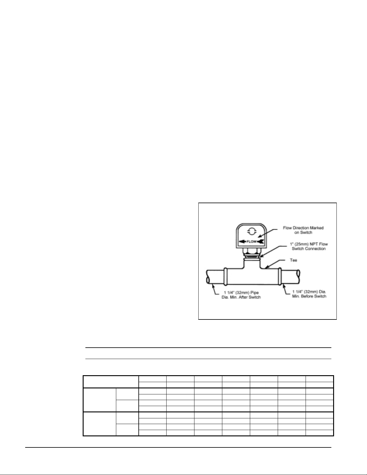
Flow Switch
Mount a water flow switch in the leaving
water line to shut down the unit when water
flow is interrupted.
Figure 5, Flow Switch Installation
A flow switch is available from McQuay
(part number 017503300). It is a “paddle”
type switch and adaptable to pipe sizes
down to 1 1/4” (32mm) nominal. Certain
minimum flow rates are required to close
the switch and are listed in Table 2. Install
the switch as shown in Figure 5. Connect
the normally open contacts of the flow
switch in the unit control center at terminals
4 and 5. There is also a set of normally
closed contacts on the switch that can be
used for an indicator light or an alarm to
indicate when a “no-flow” condition exists.
Freeze protect any flow switch that is
installed outdoors. Follow installation instructions provided with the flow switch. Calibrate the flow
switch to open at one-half of nominal flow rate.
NOTE:
Differential pressure switches are not recommended for outdoor installation.
Table 2, Flow Switch Settings
Pipe Size
Minimum
Adjustment
Maximum
Adjustment
Flow
No
Flow
Flow
No
Flow
inch 1 1/4 1 1/2 2 2 1/2 3 4
mm 32 38 51 63 76 102
gpm 4.8 6.3 9.9 15.3 24.4 33.3
Lpm 18.2 22.7 37.5 57.9 92.4 126.0
gpm 3.0 3.6 5.9 9.5 15.4 21.1
Lpm 11.3 13.6 22.3 36.0 58.3 79.9
gpm 7.7 10.0 15.8 23.7 35.5 61.4
Lpm 29.1 37.9 59.8 89.7 134.4 232.4
gpm 5.9 7.0 11.0 17.0 29.2 37.7
Lpm 22.3 26.5 41.6 64.3 110.5 142.7
8
AGZ 010A through 034A IOMM AGZ1
Page 9
Water Connections
The unit has 3-inch holes for the chilled water piping to enter the unit. The connections are made to
the evaporator water connections located within the unit. Water piping within the unit must be field
insulated.
Refrigerant Charge
All units are designed with HCFC-22. See the nameplate for specific refrigerant used. Units are
shipped with an operating charge. The operating charge (using HCFC-22) for each unit is shown in in
the Physical Data Tables on pages 13 and 14.
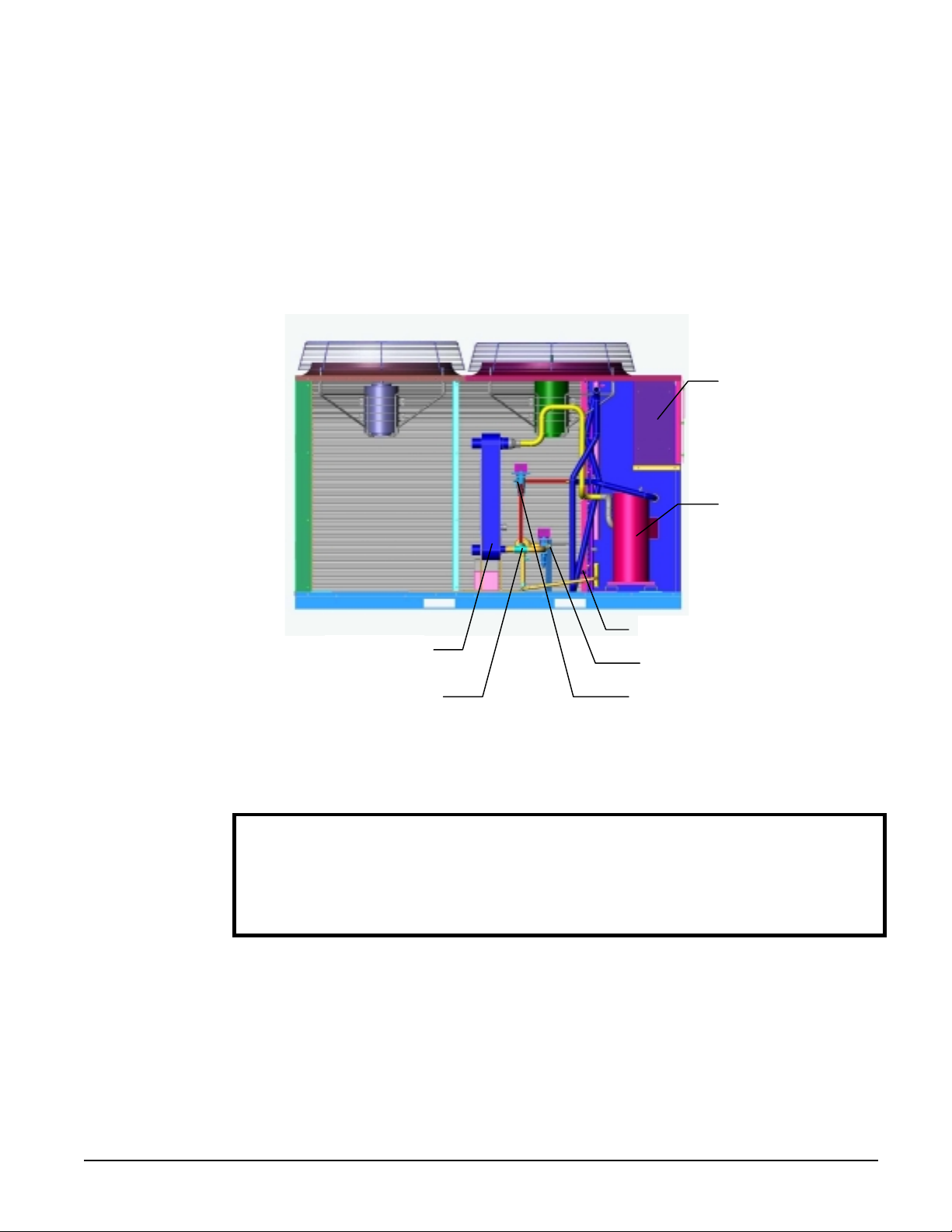
Unit Component Location
Control Panel
Tandem Scroll
Compressors
Charging Valve
Evaporator
Solenoid Valve, Expansion Valve
Optional Hot Gas Bypass ValveFilter Drier
Glycol Solutions
The use of glycol antifreeze solutions will decrease unit capacity and increase the pressure drop
through the cooler. See Product Manual PM AGZ1 for specific ratings and correction factors.
CAUTION
Do not use automotive grade antifreeze. Industrial grade glycols must be used. Autom otive
antifreeze contains inhibitors that will cause plating on the copper tubes within the chiller
evaporator. The type and handling of glycol used must be consistent with local codes.
Evaporator Water Flow and Pressure Drop
Evaporator flow rate must fall between the minimum and maximum values shown in the evaporator
pressure drop curve, Figure 6. Flow rates outside of these limits result in a chilled water Delta-T
outside the operating range of the controller.
Measure the chilled water pressur e drop through the evaporator a t field-installed p ressure taps. It is
important not to include the effect of valves or strainers in these readings.
Varying chilled water flow through the evaporator while the compressors are operating is not
recommended.
IOMM AGZ1 AGZ 010A through 034A
9
Page 10
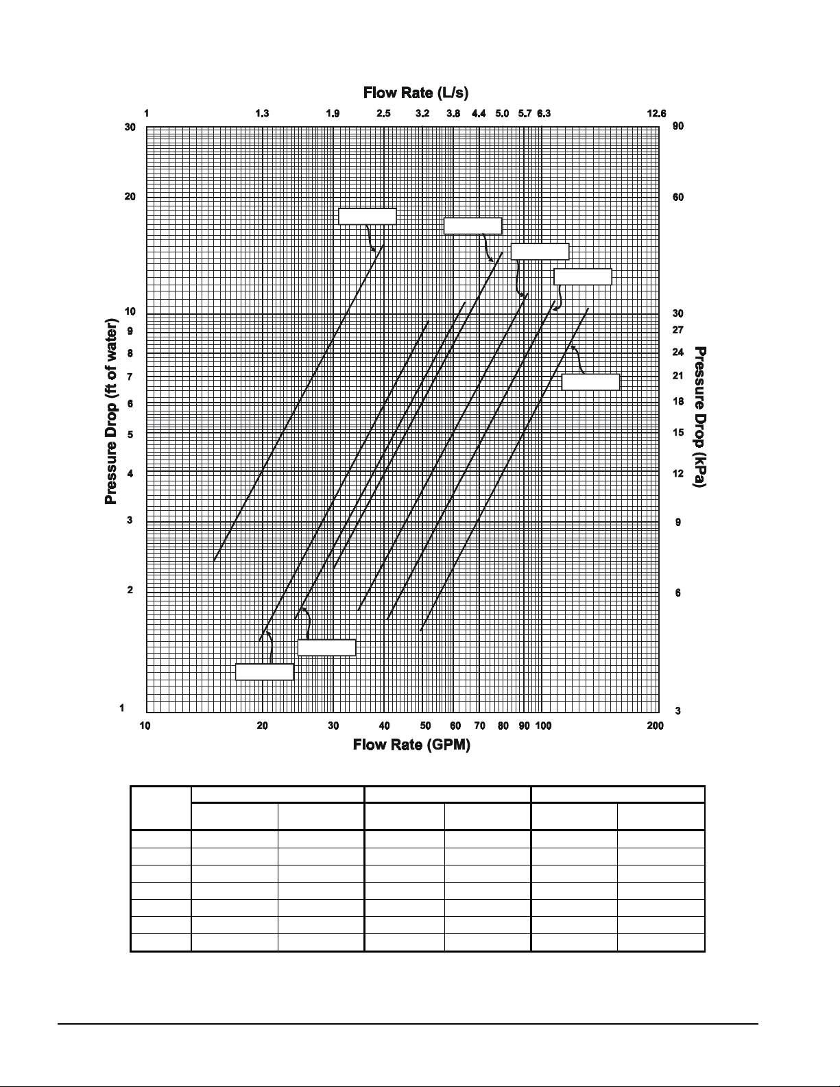
Figure 6, Evaporator Water Pressure Drop Curve
AGZ 010
AGZ 020
AGZ 025
AGZ 029
AGZ 034
10
AGZ 017
AGZ 013
AGZ
Model
010 15.0 0.9 2.4 7.1 24.0 1.5 5.8 17.3 40.0 2.5 15.2 45.5
013 19.5 1.2 1.5 4.5 31.2 2.0 3.7 11.0 52.0 3.3 9.6 28.9
017 24.0 1.5 1.7 5.0 38.4 2.4 4.1 12.2 64.0 4.0 10.7 32.1
020 30.0 1.9 2.3 6.8 48.0 3.0 5.6 16.7 80.0 5.0 14.5 43.4
025 34.5 2.2 1.8 5.3 55.2 3.5 4.3 13.0 92.0 5.8 11.4 34.3
029 40.7 2.6 1.7 5.0 65.0 4.1 4.0 12.1 108.4 6.8 10.9 32.6
034 49.8 3.1 1.6 4.7 79.7 5.0 3.9 11.7 132.8 8.4 10.4 31.2
Minimum Flow Nominal Flow Maximum Flow
Flow Rate
gpm L/s
Pressure Drop
ft. kPa
Flow Rate
gpm L/s
Pressure Drop
ft. kPa
Flow Rate
gpm L/s
Pressure Drop
ft. kPa
AGZ 010A through 034A IOMM AGZ1
Page 11
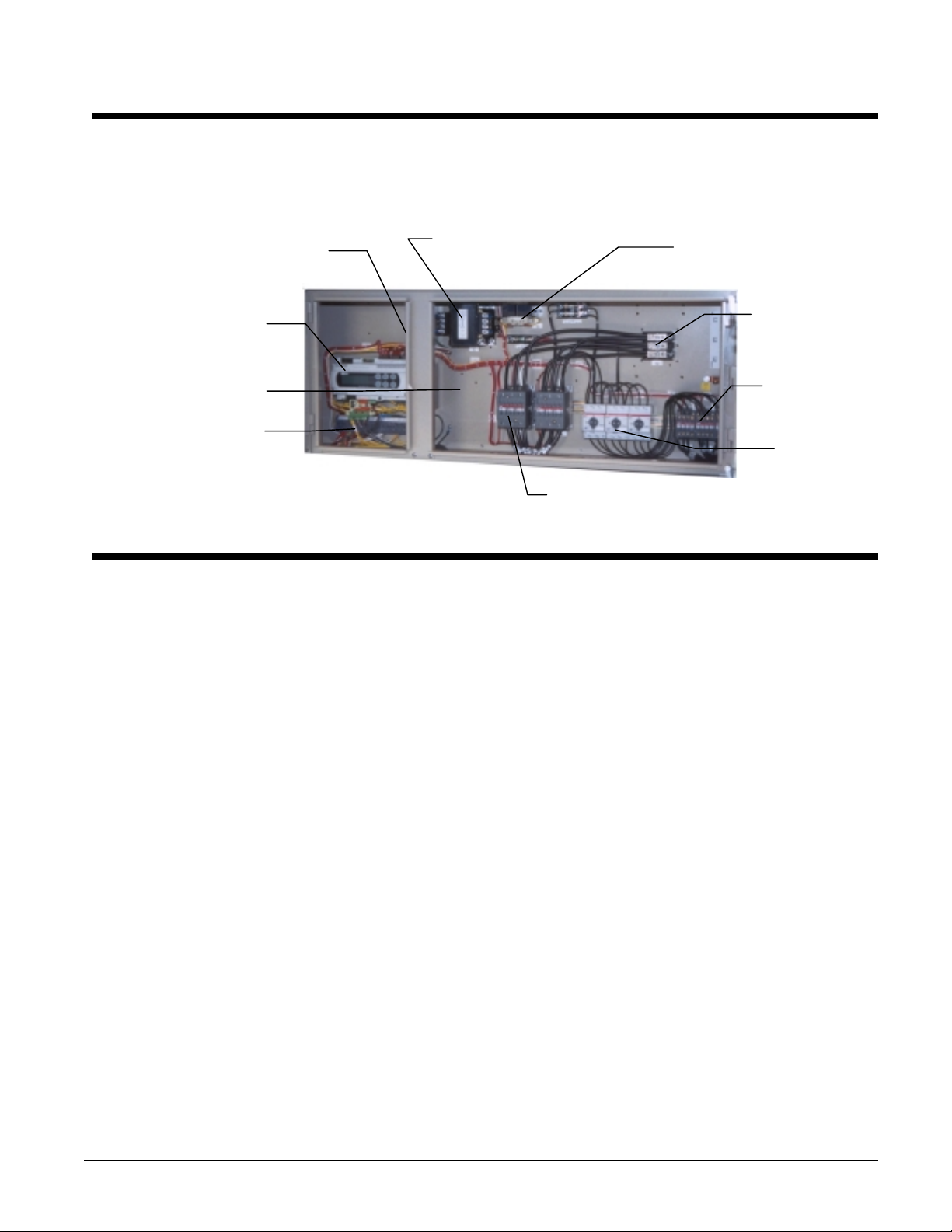
Control Layout and Operation
Control Center
All electrical controls are enclosed in a weatherproof control center with tool-locked, hinged access
doors. The left-hand section contains the microprocessor controller and control input and output
terminals. All high-voltage components are located on the right side of the panel.
ON/OFF Switch
Control
Transformer
24-Volt Trans.
MicroTech II
SpeedTrol Location
Field Connection
Terminals
Start-up and Shutdown
Pre Start-up
1. The chilled-water system should be flushed and cleaned. Proper water treatment is required to
prevent corrosion and organic growth.
2. Open all electric disconnects and check all electric connections for tightness.
3. Inspect all water piping for flow direction and correct connections at the evaporator.
4. Verify thermostat water temperature sensor is installed in the leaving water line (supply to
building). On all AGZ units the sensor well and sensor are factory mounted.
5. Check compressor oil level. The oil level should be visible in the oil sightglass.
6. Check voltage of the unit power supply and make certain voltage is within ±10% of nameplate
rating. Check unit power supply wiring for proper ampacity and a minimum insulation
temperature of 75°C. Check for proper phasing using a phase sequence meter.
7. Verify all mechanical and electrical inspections have been completed according to local codes.
8. Open control stop switch S1(off). Turn on the main power and control disconnect switches. This
will energize crankcase heaters. Wait at least 24 hours before starting up unit.
9. Open all water flow valves and start the chilled water pump. Check all piping for leaks and vent
the air from the evaporator as well as from the system piping. Flush the evaporator and system
piping to obtain clean, noncorrosive water in the evaporator.
Non-Fused Disc.
or
Power Block
Fan
Contactors
Fan
Protection
Compressor Contactors
Start-up
1. Set temperature controller to the desired chilled water temperature. Set the chilled water
Delta-T.
2. Start auxiliary equipment by turning on the following: time clock (if present), ambient thermostat
and/or remote on/off switch, chilled water pump.
3. If the controller calls for cooling, the unit will begin the start-up sequence.
4. After running the unit for a short time, check t he oil level in the compressor (1/4 to 1/3 of the
glass), rotat ion of fans, and flashing in refrigerant sightgl ass.
IOMM AGZ1 AGZ 010A through 034A
11
Page 12

5. Verify superheat temperature is at the factory setting of 8 to 12 degrees F (4.4 to 6.7 degrees C).
6. After system performance has stabilized, complete the current AGZ Start-Up Form (obtainable
from the local McQuay sales office) to establish inception of warranty benefits. Return the form
to McQuay International through your sale s representative.
Sequence of Operation
The following sequence of operation is typical for Models AGZ 010A through AGZ 034A. It can
vary depending upon options.
Start-Up
With the control circuit power on, 115V power is ap plied through the co ntrol circuit fuse F1 to the
compressor crankcase heaters, the compressor motor protections and the primary of the 24V control
circuit transformer. The 24V transformer provides power to the microprocessor controller.
When a remote time clock, manual switch, or the unit controller turns on the chilled water pump, the
flow switch closes and satisfies the flow requirement. If the chilled water temperature is above the
stage-on temperature, and all equipment protection devices are closed, the unit will start. The
controller will operate the unit in response to the leaving chiller water temperature, reset signals that
may be present and any equipment protection signals that may occur.
Equipment Protection Alarms
The following conditions will shut down the unit and activate the alarm circuit:
• No evaporator water flow Low evaporator pressure
• High condenser pressur e Motor protection system
• Phase voltage protection (Optional) Outside ambient temperature
• Evaporator freeze protection Sensor failures
The following alarms will limit unit operation:
• Condenser pressure stage down, unloads unit at high discharge p ressures
• Low ambient lockout, shuts off unit at low ambient temperatures
• Low evaporator pressure hold, holds stage #1 until pressure rises
• Low evaporator pressure unload, shuts off stage #2
12
Unit Enable Selection
Enables unit operation from local keypad, digital input, or Building Automation System.
Unit Mode Selection
Selects standard cooling, ice, glycol, or test operation mode.
Condenser fan control
Control of condenser fans is provided by the MicroTech II controller. The control steps condenser
fans based on discharge pressure.
Shutdown
As the leaving water control is satisfied, it will stage off the lag compressor unloading the unit. The
second stage will de-energize the liquid line solenoid valve SV1 and shut off the lead compressor.
The compressor crankcase heaters will energize when the compressors shut off, keeping the small
amount of refrigerant in the plate heat exchanger from migrating to the compressor. See page 38 for
detailed explanation of compressor staging.
AGZ 010A through 034A IOMM AGZ1
Page 13
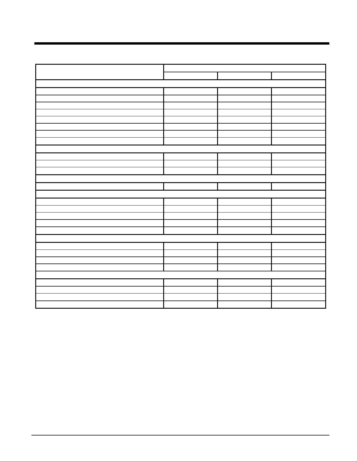
Physical Data
Table 3, Physical Data, AGZ 010A through 017A
PHYSICAL DATA
BASIC DATA
Unit Capacity @ ARI Conditions (1), Tons (kW) 9.8 (34.3) 13.3 (46.6) 15.9 (55.7)
Number Of Refrigerant Circuits 1 1 1
Unit Operating Charge, R-22, Lb. (kg) 22.0 (10.0) 24.0 (10.9) 31.0 (14.1)
Cabinet Dimensions, LxWxH, In. 73.6 x 46.3 x 50.8 73.6 x 46.3 x 50.8 73.6 x 46.3 x 50.8
Cabinet Dimensions, LxWxH, (mm) (1869) x (1176) x (1289) (1869) x (1176) x (1289) (1869) x (1176) x (1289)
Unit Operating Weight, Lb. (kg) 1090 (495) 1340 (608) 1450 (658)
Unit Shipping Wei ght, Lb. (kg) 1160 (527) 1400 (636) 1515 (688)
Add'l Weight If Copper Finned Coils, Lb. (kg) 220 (99.7) 220 (99.7) 220 (99.7)
COMPRESSORS
Type Scroll Scroll Scroll
Nominal Tons Per Compressor 6.0 / 6.0 7.5 / 7.5 9.0 / 9.0
Oil Charge Per Compressor, Oz. (g) 60 (1701) 140 (3969) 140 (3969)
CAPACITY REDUCTION STEPS - PERCENT OF COMPRESSOR DSPLACEMENT
Standard Staging 0 – 50 – 100 0 – 50 – 100 0 – 50 – 100
CONDENSERS - HIGH EFFICIENCY FIN AND TUBE TYPE WITH INTEGRAL SUBCOOLING
Coil Face Area, One of Two Sides, Sq. Ft. (M2) 30.3 (2.8) 30.3 (2.8) 30.3 (2.8)
Finned Height x Finned Length, In. 84 x 52 84 x 52 84 x 52
Finned Height x Finned Length, (mm) (2134) x (1321) (2134) x (1321) (2134) x (1321)
Fins Per Inch x Rows Deep 16 x 2 16 x 2 16 x 3
Pumpdown Capacity Lb. (kg) 35.3 (16.0) 35.3 (16.0) 50.3 (22.8)
CONDENSER FANS - DIRECT DRIVE PROPELLER TYPE
Number Of Fans - Fan Diameter, In. (mm) 2 – 26 (660) 2 – 26 (660) 2 – 26 (660)
Number Of Motors - HP (kW) 2 – 1.0 (0.75) 2 – 1.0 (0.75) 2 – 1.0 (0.75)
Fan And Motor RPM, 60 Hz 1140 1140 1140
60 Hz Total Unit Airflow, CFM (l/s) 13950 (6584) 13950 (6584) 12000 (5664)
DIRECT EXPANSION EVAPORATOR - BRAZED PLATE-TO-PLATE
Connection Size Victaul i c, In. (mm) 2 (51) 2 (51) 2 (51)
Water Volume, Gallons (L) .94 (3.6) 1.66 (6.3) 2.00 (7.6)
Maximum Refrigerant Working Pressure, psig (k P a) 450 (3103) 450 (3103) 450 (3103)
Maximum Water P ressure, psig (kPa) 350 (2413) 350 (2413) 350 (2413)
NOTE:
Nominal capacity based on 95°F ambient air and 54°F/44°F water range.
010A 013A 017A
AGZ MODEL NUMBER
IOMM AGZ1 AGZ 010A through 034A
13
Page 14
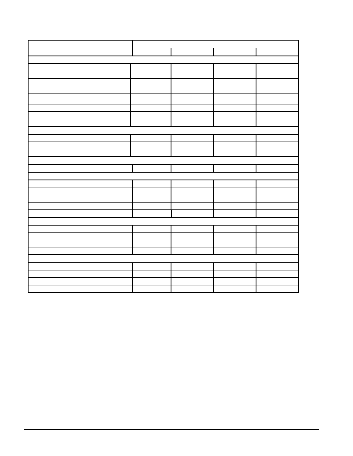
Table 4, Physical Data, AGZ 020A through 034A
PHYSICAL DATA
BASIC DATA
Unit Capacity @ ARI Conditions (1), Tons (kW) 20.4 (71.4) 22.7 (79.5) 28. 2 (98.7) 34.0 (119.0)
Number Of Refrigerant Circuits 1 1 1 1
Unit Operating Charge, R-22, Lb. (kg) 34.0 (15.4) 36.0 (16.3) 47.0 (21.3) 50.0 (22.7)
Cabinet Dimensions, LxWxH, In. 106.2x 46.3 x 50.8 106.2x 46.3 x 50.8 106.2x 46.3 x 58.8 106.2x 46.3 x 58.8
Cabinet Dimensions, LxWxH, (mm)
Unit Operating Weight, Lbs. (kg) 1620 (735) 1675 (760) 1930 (876) 2180 (990)
Unit Shipping Wei ght, Lbs. (kg) 1700 (772) 1750 (794) 2000 (908) 2230 (1012)
Add'l Weight If Copper Finned Coils, Lb. (kg) 350 (159) 350 (159) 435 (197) 435 (197)
COMPRESSORS
Type Scroll Scroll Scroll Scroll
Nominal Horsepower 10.0 / 13.0 13.0 / 13.0 15.0 / 15.0 20.0 / 20.0
Oil Charge Per Compressor, Oz. (g) 140 (3969) 140 (3969) 140 (3969) 296 (8392)
CAPACITY REDUCTION STEPS - PERCENT OF COMPRESSOR DISPLACEMENT
Standard Staging 0 – 45 - 100 0 – 50 – 100 0 – 50 – 100 0 – 50 – 100
CONDENSERS - HIGH EFFICIENCY FIN AND TUBE TYPE WITH INTEGRAL SUBCOOLING
Coil Face Area, One of Two Sides, Sq. Ft. (M2) 49.0 (4.6) 49.0 (4.6) 58.3 (5.4) 58.3 (5.4)
Finned Height x Finned Length, In. 84 x 84 84 x 84 100 x 84 100 x 84
Finned Height x Finned Length, (mm) (2134) x (2134) (2134) x (2134) (2545 ) x (2134) (2545 ) x (2134)
Fins Per Inch x Rows Deep 16 x 2 16 x 2 16 x 3 16 x 3
Pumpdown Capacity lb. (kg) 53.1 (24.0) 53.1 (24.0) 90.7 (41.1) 92.8 (42.0)
CONDENSER FANS - DIRECT DRIVE PROPELLER TYPE
Number Of Fans - Fan Diameter, In. (mm) 3 – 26 (660) 3 – 26 (660) 3 – 26 (660) 3 – 26 (660)
Number Of Motors - HP (kW) 3 – 1.0 (0.75) 3 – 1.0 (0.75) 3 – 1.0 (0.75) 3 – 1.0 (0.75)
Fan And Motor RPM, 60 Hz 1140 1140 1140 1140
60 Hz Total Unit Airflow, CFM (l/s) 20925 (9877) 20925 (9877) 19800 (9346) 19800 (9346)
DIRECT EXPANSION EVAPORATOR - BRAZED PLATE-TO-PLATE
Connection Size Victaul i c, In. (mm) 2 (51) 2 (51) 2 (51) 2 (51)
Water Volume, Gallons (L) 2.16 (8.2) 3.05 (11.5) 4.00 (15.1) 5.55 (21.0)
Max. Refrigerant Working Pressure, psig (kPa) 450 (3103) 450 (3103) 450 (3103) 450 (3103)
Maximum Water P ressure, psig (kPa) 350 (2413) 350 (2413) 350 (2413) 350 (2413)
NOTE:
Nominal capacity based on 95°F ambient air and 54°F/44°F water range.
020A 025A 029A 034A
(2697) x (1176) x
(1289)
AGZ MODEL NUMBER
(2697) x (1176) x
(1289)
(2697) x (1176) x
(1493)
(2697) x (1176) x
(1493)
14
AGZ 010A through 034A IOMM AGZ1
Page 15
Electrical Data
Field Wiring
Wiring must comply with all applicable codes and ordinances. Warranty is void if wiring is not in
accordance with specifications. Copper wire is required for all power lead terminations at the unit.
AGZ 010A through AGZ 034A units have single point power connection. A single field supplied
fused disconnect is required. The control transformer is factory mounted.
If the evaporator heater is on a separate disconnect switch from the main unit power supply, the unit
may be shut down without defeating the freeze protection provided by the evaporator heater.
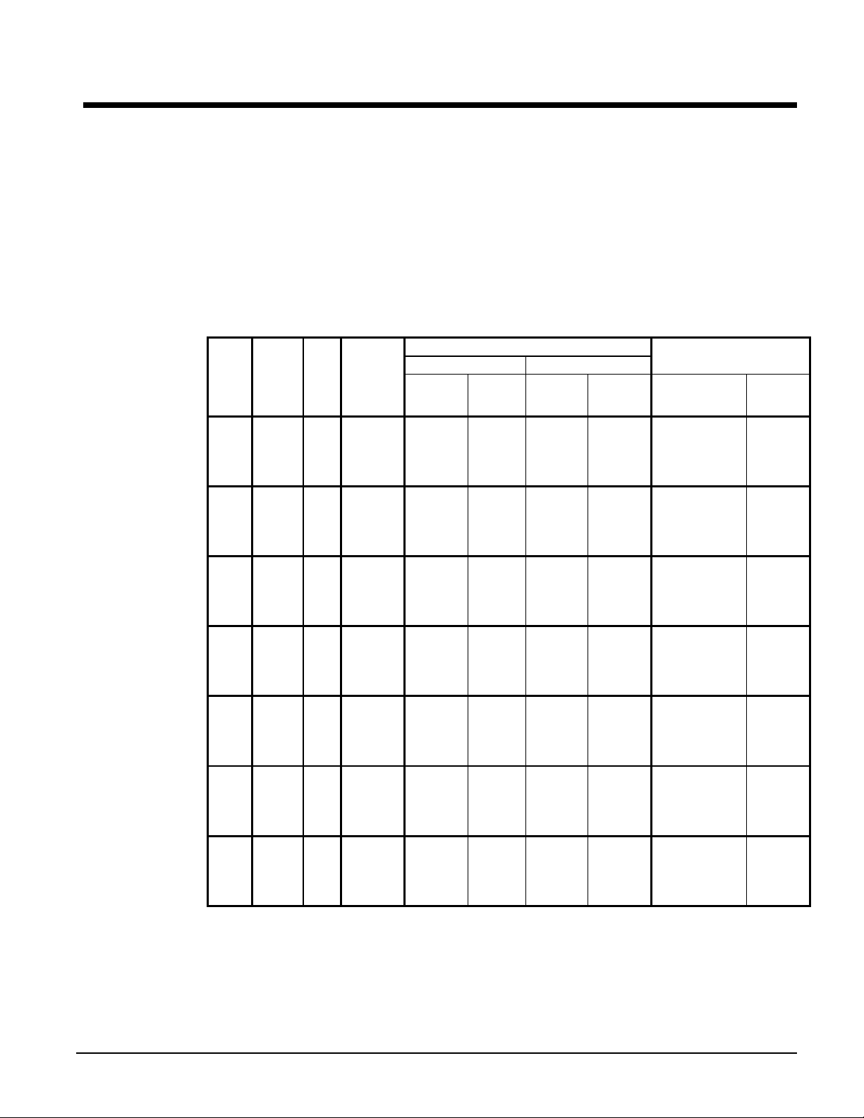
Table 5. AGZ 010A – 034A Electrical Data Single Point
AGZ
Unit
Size
010A
013A
017A
020A
025A
029A
034A
See "Electrical Notes" on page 18.
Minimum
Volts Hz.
208 54 3 6 1 1.00 (25) 60 70
230 54 3 6 1 1.00 (25) 60 70
460 26 3 10 1 1.00 (25) 30 35
575
208 65 3 6 1 1.00 (25) 80 80
230 65 3 6 1 1.00 (25) 80 80
460 34 3 10 1 1.00 (25) 40 45
575
208 79 3 4 1 1.00 (25) 90 100
230 79 3 4 1 1.00 (25) 90 100
460 41 3 8 1 1.00 (25) 45 50
575
208 103 3 2 1 1.25 (32) 125 125
230 103 3 2 1 1.25 (32) 125 125
460 53 3 6 1 1.00 (25) 60 70
575
208 110 3 2 1 1.25 (32) 125 150
230 110 3 2 1 1.25 (32) 125 150
460 58 3 6 1 1.00 (25) 70 80
575
208 136 3 1/0 1 1.50 (38) 150 175
230 136 3 1/0 1 1.50 (38) 150 175
460 62 3 6 1 1.00 (25) 70 80
575
208 175 3 2/0 1 1.50 (38) 200 225
230 175 3 2/0 1 1.50 (38) 200 225
460 88 3 3 1 1.25 (32) 100 110
575
Circuit
Ampacity
(MCA)
60
23 3 10 1 1.00 (25) 30 30
60
27 3 10 1 1.00 (25) 30 35
60
33 3 10 1 1.00 (25) 40 40
60
45 3 8 1 1.00 (25) 50 60
60
48 3 8 1 1.00 (25) 60 60
60
58 3 6 1 1.00 (25) 70 70
60
72 3 4 1 1.00 (25) 90 100
Field Wire Hub or HACR Breaker Size
Quantity
Power Supply Field Fuse Size
Wire
Gauge
Quantity
Nominal
Size
In. (mm)
Recommended Maximum
IOMM AGZ1 AGZ 010A through 034A
15
Page 16

Table 6, AGZ 010A – 034A Compressor and Condenser Fan Motor Amp Draw
AGZ
Unit
Size
010A
013A
017A
020A
025A
029A
034A
Volts Hz.
208 18.6 18.6 5.8 2 23.7 156 156
230 18.6 18.6 5.8 2 21.4 156 156
460 9.0 9.0 2.8 2 10.7 75 75
575
208 23.7 23.7 5.8 2 23.7 189 189
230 23.7 23.7 5.8 2 21.4 189 189
460 12.5 12.5 2.8 2 10.7 99 99
575
208 29.9 29.9 5.8 2 23.7 232 232
230 29.9 29.9 5.8 2 21.4 232 232
460 15.3 15.3 2.8 2 10.7 125 125
575
208 33.6 41.0 5.8 3 23.7 278 350
230 33.6 41.0 5.8 3 21.4 278 350
460 16.5 21.8 2.8 3 10.7 127 158
575
208 41.0 41.0 5.8 3 23.7 350 350
230 41.0 41.0 5.8 3 21.4 350 350
460 21.8 21.8 2.8 3 10.7 158 158
575
208 52.6 52.6 5.8 3 23.7 425 425
230 52.6 52.6 5.8 3 21.4 425 425
460 23.7 23.7 2.8 3 10.7 187 187
575
208 70 70 5.8 3 23.7 448 448
230 70 70 5.8 3 21.4 448 448
460 35 35 2.8 3 10.7 225 225
575
60
60
60
60
60
60
60
Compressors Compressors
No. 1 No. 2
7.4 7.4 3.0 2 11.5 54 54
9.1 9.1 3.0 2 11.5 74 74
11.6 11.6 3.0 2 11.5 100 100
13.7 17.3 3.0 3 11.5 100 125
17.3 17.3 3.0 3 11.5 125 125
21.7 21.7 3.0 3 11.5 148 148
28 28 3.0 3 11.5 180 180
See "Electrical Notes" on page 18.
Rated Load Amps Locked Rotor Amps
Fan
Motor
(Each)
No. of
Fan
Mtrs
Fan
Motor
(Each)
Across-The-Line
No. 1 No. 2
16
AGZ 010A through 034A IOMM AGZ1
Page 17

Table 7, AGZ 010A – 034A Field Wiring Data, Single Point Power
AGZ
UNIT
SIZE
010A
013A
017A
020E
025A
029E
034A
NOTES:
1. "Size" is the maximum amperage rating for the terminals or the main electrical device.
2. "Size" is the disconnect part number and not the amperage rating for the terminals or the main electrical device.
3. "Connection" is the range of wire sizes that the terminals on the electrical device will accept.
See page 18 for additional Electrical Notes.
Volts HZ.
208 175 14 GA – 2/0 100 8 GA – 2/0
230 175 14 GA – 2/0 100 8 GA – 2/0
460 175 14 GA – 2/0 63 14 GA – 1 GA
575
208 175 14 GA – 2/0 100 8 GA – 2/0
230 175 14 GA – 2/0 100 8 GA – 2/0
460 175 14 GA – 2/0 45 14 GA – 4 GA
575
208 175 14 GA – 2/0 175 6GA – 300 kcmil
230 175 14 GA – 2/0 175 6GA – 300 kcmil
460 175 14 GA – 2/0 45 14 GA – 4 GA
575
208 175 14 GA – 2/0 200 6GA – 300 kcmil
230 175 14 GA – 2/0 200 6GA – 300 kcmil
460 175 14 GA – 2/0 160 8 GA – 1/0
575
208 175 14 GA – 2/0 200 6GA – 300 kcmil
230 175 14 GA – 2/0 200 6GA – 300 kcmil
460 175 14 GA – 2/0 160 8 GA – 1/0
575
208 175 14 GA – 2/0 200 6GA – 300 kcmil
230 175 14 GA – 2/0 200 6GA – 300 kcmil
460 175 14 GA – 2/0 160 8 GA – 1/0
575
208 335 6 GA – 400 kcmil N/A ----230 335 6 GA – 400 kcmil 200 6GA – 300 kcmi l
460 175 14 GA – 2/0 175 6GA – 300 kcmil
575
60
60
60
60
60
60
60
Standard Power Block Terminal
Maximum
Terminal
Amps (1)
175 14 GA – 2/0 63 14 GA – 1 GA
175 14 GA – 2/0 63 14 GA – 1 GA
175 14 GA – 2/0 63 14 GA – 1 GA
175 14 GA – 2/0 160 8 GA – 1/0
175 14 GA – 2/0 160 8 GA – 1/0
175 14 GA – 2/0 160 8 GA – 1/0
175 14 GA – 2/0 175 6GA – 300 kcmil
Wiring to
Connector Wire Range
(Copper Wire Only) (3)
Optional Disconnect Switch
Disconnect
Size (2)
Wiring to
Connector Wire Range
(Copper Wire Only) (3)
IOMM AGZ1 AGZ 010A through 034A
17
Page 18

Notes for “Electrical Data Single Point"
1. Field Fuse Size for recommended and maximum is based on use of a time-delay fuse.
2. Unit wire size ampacity (MCA) is equal to 125% of the largest compressor-motor RLA plus
100% of RLA of all other loads in the circuit including the control transformer.
3. Since the control transformer is furnished, no separate 115v power is required.
4. If a separate 115V power supply is used for the control circuit, then the wire sizing amps is 2
Amps.
5. Recommended power lead wire sizes for 3 conductors per conduit are based on 100% conductor
ampacity in accordance with NEC. Voltage drop has not been included. Therefore, it is
recommended that power leads be kept short. All terminal block connections must be made with
copper (type THW) wire.
6. Single conductors should be used for power connections as listed under “Recommended Power
Lead Wire Size.”
7. “Recommended Fuse Sizes” are selected at approximately 150% to 225% of the largest
compressor RLA, plus 100% of all other loads in the circuit.
8. “Maximum Fuse Sizes” are selected at approximately 225% of the largest compressor RLA, plus
100% of all other loads in the circuit.
9. The recommended power lead wire sizes are based on an ambient temperature of 86°F.
Ampacity correction factors must be applied for other ambient temperatures. Refer to the
National Electrical Code Handbook.
Power Limitations:
1. Voltage within 10% of nameplate rating.
2. Phase imbalance within 3%.
Notes for “Compressor and Condenser Fan Amp Draw”:
1. Compressor RLA values are for wiring sizing purposes only but do not reflect normal operating
current draw at rated capacity.
Notes for “Field Wiring Data” - Single Point Power:
1. Single point power supply requires a single disconnect to supply electrical power to the unit.
This power must be fused.
2. All field wiring to unit power block or non-fused disconnect switch must be copper.
3. All field wire size values given in table apply to 75°C rated wire per NEC.
18
AGZ 010A through 034A IOMM AGZ1
Page 19

Figure 7, AGZ 010A through AGZ 034A, Typical Field Wiring Diagram
(BY OTHERS OR
FACTORY OPTION)
3 PHASE
POWER
SUPPLY
OPTIONAL REMOTE
120 VAC CONTROL POWER
SEPARATE EVAPORATOR
HEATER POWER
OPTION
120VAC
(BY OTHERS)
ALARM BELL
OPTION
REMOTE STOP
(BY OTHERS)
CHW FLOW SWITCH
--MANDATORY-(BY OTHERS)
DISCONNECT
DISCONNECT
(BY OTHERS)
N
DISCONNECT
(BY OTHERS)
N
FIELD WIRED
ALARM BELL
RELAY
TIME
CLOCK
UNIT MAIN
TERMINAL BLOCK
FUSED CONTROL
CIRCUIT TRANSFORMER
10A
FUSE
(BY OTHERS)
10A
FUSE
(BY OTHERS)
CHW PUMP RELAY
(BY OTHERS)
120 VAC 1.0 AMPS MAX
OFF
AUTO
ON
MANUAL
GND LUG
TO COMPRESSOR(S)
AND FAN MOTORS
120 VAC
TB1-20
TB1
1
CONTROL
CIRCUIT
FUSE
2
6
15
12
TB2
17
11
17
GND
25
35
IF REMOTE STOP CONTROL
843
IS USED, REMOVE LEAD 843
MJ
IF SEPARATE EVAPORATOR
HEATER POWER OPTION
MJ
N
FROM TERM 25 TO 35.
IS USED - REMOVE
MECHANICAL JUMPER
BETWEEN TB1-5 AND
TB1-6 & TB1-15 AND
120 VAC
120 VAC
TB1-16
NOR. OPEN PUMP AUX.
CONTACTS (OPTIONA L)
4-20 MA FOR
CHW RESET
(BY OTHERS)
OFF
AUTO
ICE MODE SWITCH
(BY OTHERS)
330258401
ON
MANUAL
Rx-/Tx-
Rx+/Tx+
GND
Note: See control and power wiring diagrams on unit control panel for specific unit information.
IOMM AGZ1 AGZ 010A through 034A
J11
26
36
22
33
34
GND
28
38
1
*
COMMUNICATION
2
3
PORT
19
Page 20

Dimensional Data
Figure 8, AGZ 010A through 017A
5.11 (129.79)
0.875 (22.23)
POWER ENTRY
KNOCKOUT
(OTHER SIDE)
0.875
(22.23)
CONTROL
ELECTRICAL
KNOCKOUT
39.63
(1006.6)
24.00
(609.6)
3.88 (98.55)
MOUNTING HOLES
QTY. 4 01.00
.
AIR
FLOW
ACCESS
PANEL
14.59
(370.59)
Y
AGZ
Unit Size
3.00
(78.20)
QTY. 2
EVAP.
INLET
EVAP.
OUTLET
(286.26)
11.27
31.70
(805.18)
Z
49.06
73.57
(1868.68)
(1246.12)
(1173.48)
46.20
21.12
(536.45)
X
Center of Gravity
Inches (mm)
XYZ
AGZ 010 27.8 (706.1) 22.7 (576.6) 19.2 (487.7) 2
AGZ 013 24.3 (617.2) 22.5 (571.5) 19.1 (485.1) 2
AGZ 017 24.4 (619.8) 22.4 (569.0) 19.1 (485.1) 2
Figure 9, AGZ 020A through 034A
46.14
AIR
(1171.96)
FLOW
CONTROL
PANEL
ACCESS
DOORS
ACCESS DOOR
30.91
(785.11)
MOUNTING
HOLES
7.75
(196.85)
Evaporator Connection
Size
Inch Victaulic
POWER
ENTRY
AIR
FLOW
51.00
(1295.40)
ACCESS
PANEL
Y
AGZ
Unit Size
14.59
(370.59)
3.00
(76.20)
QTY. 2
EVAP.
INLET
EVAP.
OUTLET
11.27
(286.26)
31.70
(805.18)
Z
49.0
(1246.12)
MOUNTING HOLES
QTY. 6 01.00 (25.40)
Dimensions
Inches (mm)
106.15
(2696.21)
49.06
(1246.12)
(1173.48)
5.11 (129.79)
46.20
X
21.12
(536.45)
0.875 (22.23)
POWER ENTRY
KNOCKOUT
(OTHER SIDE)
0.875
.
(22.23)
CONTROL
ELECTRICAL
KNOCKOUT
B
3.88
AIR
FLOW
A
(98.55)
Center of Gravity
Inches (mm)
AB C XY Z
AIR
FLOW
CONTROL
PANE L
ACCESS
DOORS
ACCESS DOOR
30.91
(785.11)
MOUNTING
HOLES
AGZ 020 24.0 (609. 6) 39.6 (1006.6) 51.0 (1295.4) 33.8 (858.5) 22.4 (569.0) 20.2 (513.1) 2
AGZ 025 24.0 (609. 6) 39.6 (1006.6) 51.0 (1295.4) 33.7 (856.0) 22.2 (564.0) 20.1 (510.5) 2
AGZ 029 33.0 (838. 2) 47.6 (1209.8) 59.0 (1498.6) 36.5 (927.1) 23.1 (586.7) 22.6 (574.0) 2
AGZ 034 33.0 (838. 2) 47.6 (1209.6) 59.0 (1498.6) 35.0 (889.0) 23.1 (586.7) 21.4 (543.6) 2
46.14
(1171.96)
POWER
ENTRY
AIR
FLOW
7.75
(196.85)
Evaporator
Connection Size
Inch Victaulic
C
20
AGZ 010A through 034A IOMM AGZ1
Page 21

System Maintenance
General
On initial start-up and periodically during operation, it will be necessary to perform certain routine
service checks. Among these are taking electric leg readings. Some readings are readily available on
the MicroTech II display.
Lubrication
No routine lubrication is required on the AGZ units. The fan motor bearings are of the permanently
lubricated type and require no lubrication.
Electrical Terminals
WARNING
Electric shock hazard. Turn off all power before continuing with following service.
Normal heating and cooling of the wire will cause terminals to loosen. Retighten all power electrical
terminals every six months.
Condensers
Condensers are air-cooled and constructed with 3/8” (9.5mm) O.D. internally finned copper tubes
bonded in a staggered pattern into slit aluminum fins. No maintenance is ordinarily required except
the occasional removal of dirt and debris from the outside surface of the fins. Use locally purchased
foaming condenser coil cleaners for periodic cleaning of the coil. Condenser cleaners may contain
harmful chemicals, be careful when using cleaners. Care should be taken not to damage the fins
during cleaning. All chemical cleaners sho uld be thoroughly ri nsed from the coils.
Refrigerant Sightglass
Observe the refrigerant sightglass monthly. A clear glass of liquid indicates adequate sub-cooled
refrigerant charge in the system to ensure proper feed through the expansion valve. Bubbling
refrigerant in the sightglass indicates the system is short of refrigerant charge. Sub-cooling should be
verified to prevent overcharging. Refrigerant gas flashing in the sightglass could also indicate an
excessive pressure drop in the line, possibly due to a clogged filter-drier or a restriction elsewhere in
the system. The sightglass indicates what moisture condition corresponds to a given element color. If
the sightglass does not indicate a dry condition after about 12 hours of operation, the refrigerant or oil
should be tested for moisture.
IOMM AGZ1 AGZ 010A through 034A
21
Page 22

Standard MicroTech II Controller
Table of Contents
Overview............................................................................. 23
General Description............................................................. 23
Compressor Motor Description.......................................23
FanTrol Head Pressure Control .......................................23
Inputs/Outputs................................................................ 24
Setpoints ........................................................................24
Equipment Protection Alarms......................................... 26
Limit Alarms..................................................................26
Unit Enable ....................................................................26
Unit Mode Selection .......................................................27
Low Ambient Start .........................................................27
Automatic Adjusted Range Limits..................................28
Compressor Staging Parameters......................................28
Using the Controller ............................................................30
Display and Keyboard.....................................................30
Getting Started.....................................................................30
Menu Screens.................................................................31
Menu Matrix ..................................................................33
View Screens Defined.....................................................34
Alarm Screens Defined...................................................36
Set Screens Defined........................................................36
22
AGZ 010A through 034A IOMM AGZ1
Page 23

Overview
MicroTech II’s state-of-the-art design will not only permit the chiller to run more efficiently, but will
also simplify troubleshooting if a system failure occurs. Every MicroTech II controller is
programmed and tested prior to shipment to contribute to a trouble-free start-up.
Operator-friendly
The MicroTech II menu structure is separated into three distinct categories, which provide the
operator or service technician with a full description of current unit status, control parameters, and
alarms. Security protection prevents unauthorized changing of the setpoints and control parameters.
MicroTech II continuously performs self-diagnostic checks, monitoring system temperatures,
pressures and protection devices, and will automatically shut down a compressor or the entire unit
should a fault occur. The cause of the shutdown will be retained in memory and can be easily
displayed in plain English for operator review. T he MicroTech II chiller controller will also retain
and display the time the fault occurred. In addition to displaying alarm diagnostics, the MicroTech II
chiller controller also provides the operator with a warning of limit (pre-alarm) conditions.
Staging
The two scroll compressors are staged on and off as a function of leaving chilled water temperature.
Lead/lag is automatic and switched every ten starts.
General Description
Compressor Motor Protection
AGZ 013 – 034:
off” relay utilizing the bleed-down capacitor principle. Any time the protection system opens or
power to the module is interrupted, the 2-minute “time-off” delay is triggered and the module will not
reset for two minutes. Once the 2-minute period has passed the motor protector contacts M1 and M2
reset, provided the protection system is satisfied and power is applied to the module.
Note:
If the power circuit is broken onc e the 2-minute period is passed, the pilot circuit will
reset without delay when power is reapplied.
AGZ 010:
The solid-state compressor motor protector module incorporates a 2-minute “time-
The model AGZ 010 compressor has internal line breakage with automatic reset.
FanTrol Head Pressure Control
FanTrol is the standard method of head pressure control that automatically cycles the condenser fan
motors in response to condenser pressure. This function is controlled by the microprocessor,
maintains head pressure and allows the unit to run at low ambient air temperatures down to 35°F
(1.7°C). Fans are staged as follows:
Table 8, Fan Staging Pressures
Fan Two-Fan Unit Three-Fan Unit
Stage #1 On 150 psig, Off with unit On 150 psig, Off with unit
Stage #2 On 290 psig, Off 170 psig On 290 psig, Off 170 psig
Stage #3 On 310 psig, Off 180 psig
Note: Fan #1 is on with first compressor above 75°F (24°C).
IOMM AGZ1 AGZ 010A through 034A
23
Page 24

Inputs/Outputs
Table 9, Inputs and Outputs
Analog Inputs
# Description Signal Source Range
1 Reset of Leaving Water Temperature 4-20 mA Current 0-(10 to 80°F)
2 Evaporator Refrigerant Pres sure 0.1 to 0.9 VDC 0 to 132 psi
3 Condenser Refrigerant Pressure 0.1 to 0.9 V DC 3.6to 410 psi
4 Leaving Evaporator Water Temperature
5 Outside Ambi ent Temperature
Thermister (10k at 77°F, 25°C)
Thermister (10k at 77°F, 25°C)
Analog Outputs
# Description Output Signal Range
1 None
Digital Inputs
# Description Signal Signal
1 Unit OFF Switch 0 VAC (Stop) 24 VAC (Auto)
2 Remote Start / Stop 0 VAC (Stop) 24 VAC (Start)
3 Evaporator W at er Fl ow Switch 0 VAC (No Flow) 24 VAC (Flow)
4 Motor Protection 0 VAC (Fault) 24 VAC (No Fault)
5 Ice Mode Switch 0 VAC (Normal ) 24 VAC (Ice )
6 Phase Voltage Fault 0 VAC (Fault) 24 VAC (No Fault)
7 Open
8 Open
Digital Outputs
# Description Load Output OFF Output ON
1 Alarm Alarm Indicator Alarm OFF Alarm ON
2 Evaporator W ater Pump Pump Contac tor Pump OFF Pump ON
3 Liquid Line Solenoid Cool i ng OFF Cooling ON
4 Motor Control Relay #1 Starter Compressor OFF Compressor ON
5 Motor Control Relay #2 Starter Compressor OFF Compressor ON
6 Condenser Fan #1 Fan Contactor Fan OFF Fan ON
7 Condenser Fan #2 Fan Contactor Fan OFF Fan ON
8 Condenser Fan #3 Fan Contactor Fan OFF Fan ON
-58 to 212°F
-58 to 212°F
24
Setpoints
The setpoints shown in Table 10 are battery-backed and remembered during power off, are factory set
to the
Default
The PW (password) column indicates the password level that must be entered in order to change the
setpoint. Passwords are as follows:
O = Operator [0100]
M = Manager, M level settings are not normally changed for chilled water air-conditioning
applications.
value, and can be adjusted within the value shown in the
AGZ 010A through 034A IOMM AGZ1
Range
column.
Page 25

Table 10, Setpoints
Description Default Range PW
Unit
Unit Enable OFF OFF, ON O
Unit Mode COOL
Control Source SWITCHES
Available Modes COOL
Display Units
Language ENGLISH ENGLISH, O
Evap LWT (COOL & GLYCOL)
Ice LWT (ICE)
Evap Delta T
Startup Delta T
* Condenser Fans Stages 2 2,3 M
* Phase Voltage Protecti on N N,Y M
* SpeedTrol Option N N,Y M
Staging
Stage Up Delay 120 20 to 240 sec M
Stage Down Delay 30 10 to 60 sec M
Timers
Evap Flow Proof 5 sec 3 to 120 sec M
Low Evap Pressure Delay 30 sec 15 sec to 30sec M
Start-Start 15 min 10 t o 60 min M
Stop-Start 5 min 3 to 20 min M
Alarms
Evaporator Freeze
Low Evap Pressure 58 psi 30 to 60 psi M
Low Evap Pressure-Hold 59 psi 31 to 65 psi M
Low Evap Pressure-Unload 59 psi 31 to 65 psi M
High Condenser Stage Down 370 psi 365 to 375 psi M
High Condenser Pressure 380 psi 380 to 390 psi M
* Low Ambient Lockout
Condenser Fans
Fan Stages 2 2-3
Stage #1 On 150psi 140 to 200 psi M
Stage #2 On 290 psi 230 to 330 psi M
Stage #3 On 310 psi 230 to 330 psi M
Stage #1 Off Off Off with Stage #1 M
Stage #2 Off 170 psi 150 to 200 psi M
Stage #3 Off 180 psi 150 to 200 psi M
Sensor Offsets
Evaporator Refrig Press Sensor Offset 00.0 psi -20.0 to 20. 0 psi
Condenser Refrig Press Sensor Of fset 00.0 psi -20.0 to 20.0 ps i
Leaving Evaporator Water Temp Sensor
Outside Ambient Temperature Sensor
(*) These items are factory set prior to shipment.
F/psi
°
44. 0°F 20.0 to 60.0 °F
40. 0°F 20.0 to 40.0 °F
10. 0°F 6.0 to 16.0 °F
2.0°F 1.0 to 10.0 °F
36.0 °F 18 to 42 °F
35.0 °F –2 to 60 °F
0.0 °F -5.0 t o 5.0 °F
0.0 °F -5.0 t o 5.0 °F
COOL
COOL w/Glycol
ICE w/Glycol
TEST
SWITCHES, KEYPAD,
NETWORK
COOL
COOL w/GLYCOL
COOL/ICE w/GLYCOL
TEST
F/psi
°
O
O
M
O
O
O
O
O
M
M
IOMM AGZ1 AGZ 010A through 034A
25
Page 26

Equipment Protection Alarms
Equipment protection alarms execute rapid compressor shutdown.
The following table identifies each equipment protection alarm, gives the condition that causes the
alarm to occur, and states the action taken because of the alarm. If the alarm is auto-clearing, the
reset condition is shown below. Otherwise, the alarm is manually reset, requiring the operator to clear
the alarm.
Table 11, Shutdown Alarms
Description Occurs When:
No Evaporator Water Flow
Low Evaporator Pressure
High Condenser Pressure
Motor Protection
Phase Voltage Protecti on
(opt)
Low Ambient Restart Fault
Evaporator Freeze Protect Evap LWT < Evaporator Freeze SP Rapid Stop Manual
Leaving Evaporator Water
Temperature Sensor Fault
Evaporator Pressure Sensor
Fault
Condenser Pressure Sensor
Fault
Outside Ambient
Temperature Sensor Fault
NOTE: SP=SetPoint
Evap Pump State = RUN and Flow Switch
Digital Input = No Flow and time greater t han
Evap Flow Proof SP
Evaporator Press < Low Evap Pressure SP start
Low Evap Pressure Time Delay – if after Ti me
Delay if Evap Press > SP c ontinue else stop
Condenser Press > High Condenser Pressure
SP
Digital Input = High Motor Temperat ure
On Power Up – Delay 150 Sec. before checking
If Phase Voltage Protection = Y, Then Digital
Input = Phase/Voltage Probl em
Failed three consecutive low ambient start
attempts
Sensor shorted or open Rapid Stop Manual
Sensor shorted or open Rapid Stop Manual
Sensor shorted or open Rapid Stop Manual
Sensor is open or shorted Rapid Stop Manual
Action
Taken
Rapid Stop
Rapid Stop Manual
Rapid Stop Manual
Rapid Stop Manual
Rapid Stop
Rapid Stop Manual
Reset
Flow Switch
Closes
Phase/Voltage
Input Returns
to Normal
Limit Alarms
The following alarms limit the operation of the chiller in some way as described in the Action Taken
column. These alarms are auto-clearing based on reaching the conditions in the reset column.
Table 12, Limit Alarms
Description Occurs When: Action Taken Reset
Condenser Pressure
Stage Down
Low Ambient
Lockout
Low Evaporator
Pressure – Hold
Low Evaporator
Pressure – Unload
NOTE: SP = Set Point
Pressure > High Condenser Stage
Down setpoint
Any compressor is running AND
Outside Ambient < Low Amb Lockout
SP
Pressure < Low Evap Pressure–Hold
setpoint
Pressure < Low Evap Pressure–
Unload setpoint
Shutoff
Stage #2
Shutoff Stages #1
& #2
Hold @
Stage 1
Shutoff
Stage 2
Condenser Press drops
below (SP – 100psi)
Outside Ambient > Low
Amb Lockout
(SP + 5ºF)
Evap Press rises above
(SP + 8psi)
Evap Press rises above
(SP + 10 psi)
Unit Enable
Enabling and disabling the chiller is controlled by the Unit Enable Setpoint with options of OFF and
ON. This setpoint can be altered by the Unit Off Input, Remote Input, keypad entry, or BAS request.
The Control Source setpoint determines which source can change the Unit Enable setpoint with
options of SWITCHES, KEYPAD, or NETWORK
Changing the Unit Enable Setpoint can be accomplished according to the following table.
26
AGZ 010A through 034A IOMM AGZ1
Page 27

Table 13, Unit Enable Conditions
Unit Off
Input
OFFxxxxOFF
x SWITCHES OFF x x OFF
ON SWITCHES ON x x ON
ON KEYPAD X OFF x OFF
ON KEYPAD X ON x ON
ON NETWORK x x OFF OFF
On NETWORK OFF x x OFF
ON NETWORK ON x ON ON
NOTE: An “x” indicates that the value is ignored
Control Source
Set Point
Remote Input Keypad Entry BAS Request Enable
Unit Mode Selection
The overall operating mode of the chiller is set by the Unit Mode Setpoint with options of COOL,
COOL w/Glycol, ICE w/Glycol, and TEST. This mode setting can be altered by the keypad, BAS,
and Mode input. Changes to the Unit Mode Set Point are controlled by two additional setpoints.
•
Available Modes Setpoint: Determines the operational modes available at any time with options
of COOL, COOL w/Glycol, COOL/ICE w/Glycol, and TEST.
•
Control Source Setpoint: Determines the source that can change the Unit Mode Set Point with
options of KEYPAD, NETWORK, or SWITCHES.
Changing the Unit Mode Setpoint can be accomplished according to the following table.
Table 14, Unit Mode Selection
Control Source
Set Point
x x x x COOL COOL
x x x x COOL w/Glycol COOL w/Glycol
SWITCHES OFF x x COOL/ICE w/Glycol COOL w/Glycol
SWITCHES ON x x COOL/ICE w/Glycol ICE w/Glycol
KEYPAD x COOL w/Glycol x COOL/ICE w/Glycol COOL w/Glycol
KEYPAD x ICE w/Glycol x COOL/ICE w/Glycol ICE w/Glycol
NETWORK x x COOL COOL/ICE w/Glycol COOL w/Glycol
NETWORK x x ICE COOL/ICE w/Glycol ICE w/Glycol
x x x x TEST TEST
NOTE: An “x” indicates that the value is ignored.
Mode
Input
Keypad Entry
BAS
Request
Available Modes
Set Point
Unit Mode
Low Ambient Start
If SpeedTrol = N, the unit will start in the normal operation. If the SpeedTrol = Y then starting will
follow table below. This step will bypass the “Low Evaporator Pressure” alarm until Low Ambient
Start is completed.
Low Ambient Start Method
Table 15, Low Ambient Start Sequence
Description Occurs When: Action Taken
Check #1
Check #2
Check #3
Check #4
Low Ambient Restart
If the Evap Pressure fails during the low-ambient start, the controller will wait until the anti-cycle
timers expire then try to restart. It will allow unit to attempt to start 3 times. If the unit starts
successfully, the counter is reset. If it fails to start on the third attempt, the Low Ambient Restart
Alarm Fault (Manual Reset) will be activated.
IOMM AGZ1 AGZ 010A through 034A
After 15 Seconds after starting Lead Compressor, I f the
Evap Press is < 28 take Action or else continue
After 15 Seconds after Check #1, If the Evap Press is < 38
take Action or else c ontinue
After 15 Seconds after Check #2, If the Evap Press is < 48
take Action or else c ontinue
After 15 Seconds after Check #3, If the Evap Press i s <
Low Evap Pressure SP take Act i on or el se continue in
normal operation
Rapid Stop – See Low Ambient
Re-Start below
Rapid Stop – See Low Ambient
Re-Start below
Rapid Stop – See Low Ambient
Re-Start below
Rapid Stop – See Low Ambient
Re-Start below
27
Page 28

Automatic Adjusted Limits
The following setpoint ranges will be adjusted automatically based on selected options or mode of
operation.
Evaporator Leaving Water Temperature
Mode Range
Unit Mode = Cool
Unit Mode = Cool w/ Gycol
Evaporator Freeze Temperature
Mode Range
Unit Mode = Cool
Unit Mode = Cool w/Glycol,
Ice w/ Glycol
Low Evaporator Pressure
Mode Range
Unit Mode = Cool 55 to 60 Psig
Unit Mode = Cool w/Glycol,
Ice w/ Glycol
Low Evaporator Pressure Hold and Unload
Mode Range
Unit Mode = Cool 55 to 65 Psig
Unit Mode = Cool w/Glycol,
Ice w/ Glycol
40 to 60°F
20 to 60°F
36 to 42°F
18 to 42°F
30 to 60 Psig
31 to 65 Psig
Low Ambient Lockout Temperature
SpeedTrol Range
SpeedTrol = N
SpeedTrol = Y
35– 60°F
-2 – 60°F
Compressor Staging Parameters
The following table gives the rules for staging the two compressors. This is further explained in the
MENU section of the manual.
Cool, Glycol
Description Occurs When: Action Taken
Stage #1 ON
Stage #2 ON
Stage #2 OFF
Stage #1 OFF
Note: CB (Control Band) = Evap W ater Delta T x .6
ICE
In ICE mode, the controller stages ON the compressors to stage 2 as shown above until the LWT is <
the ICE LWT SP. At this point compressors #1 and #2 shut down simultaneously.
Lvg Evap T > Evap LWT SP + (CB/2) +
Startup Delta T
After Stage Up Delay times out then, LVG
Evap T > Evap LWT SP + (CB/2)
After Stage Down Delay times out then, LVG
Evap T < Evap LWT SP - (CB/2)
After Stage Down Delay times out then, LVG
Evap T < Evap LWT SP - (CB/2)
Lead Compressor ON
Lag Compressor ON
Lag Compressor OFF
Lead Compressor OFF
28
Compressor Lead/ Lag
The compressor designated as the lead will be the first to start and the last to shut off. Lead/lag
designation is switched based on the number of starts. After 10 starts on Compressor #1 as lead,
Compressor #2 starts as Lead for 10 starts, and then the cycle is repeated.
AGZ 010A through 034A IOMM AGZ1
Page 29

Capacity Overrides
The following conditions will override the capacity control when the chiller is in the cool and ice
modes.
Low Evaporator Pressure
If the unit is running at stage 1 and the evaporator pressure drops below the Low Evaporator
Pressure-Hold setpoint, the unit will hold at stage 1. This condition will inhibit the unit from loading
until the evaporator pressure reaches the hold setpoint plus 8 psi.
If the unit is running at stage 2 and the evaporator pressure drops below the Low Evaporator
Pressure-Unload setpoint, the unit will unload to stage 1. This condition will inhibit the unit from
loading until the evaporator pressure reaches the hold setpoint plus 10 psi.
Maximum LWT Rate
The maximum rate at which the leaving water temperature can drop shall be limited at all times by the
Maxi mum Rate s etpoi nt (2°F/Minute). If the rate exceeds this setpoint, capacity increases shall be
held at Stage 1. This limit is no t adjusta ble through t he keypad and d oes not have a presenc e in any
alarm menu.
Discharge Pressure Stage Down
If the unit is running at stage 2 and the condenser pressure rise s above the High Co ndenser Pre ssure
Stage Down setpoint, the unit will unload to stage 1. This condition will inhibit the unit from loading
until the condenser pressure drops below the unload setpoint less 100 psi.
Digital Output Control
Each digital output is controlled according to the following rules and in accordance with whether the
unit is in normal operation or TEST (test mode). All outputs are initialized to OFF at power on.
Alarm – (J12 – NO1)
This output is turned ON when any “EQUIPMENT PROTECTION ALARMS” occur. It is turned
OFF when all alarms have been cleared.
Evaporator Pump – (J12 – NO2)
The Evaporator Water Pump output is ON if the Evap State is set to START or RUN.
Liquid Line Solenoid – (J12 – NO3)
This output is ON when the Compressors are ON. It is OFF for all other cases.
Motor Control Relay #1, #2 – (J13 – NO4, J13 – NO5)
This output is ON when the Compressors are ON. It is OFF for all other cases.
Fan #1, #2, & #3 – (J13 – NO6, J14 – NO7, J15 – NO8)
Condenser Fans Staging is based on Condenser pressure as selected Fan Stage On & Off setpoints.
Evaporator Water Pump State Control (Evap State)
The state-transition diagram
Power ON
Unit =OFF or Unit =ALARM
TEST:
RUN
OFF
Unit Enable =
TEST:
OFF
Flow OK for
TEST:
30 Seconds
Unit Enable = ON
TEST:
START
shown to the left controls
operation of the evaporator pump.
A state variable (Evap State) shall
be used to maintain the current
state (OFF, START, or RUN).
The 30-second timer shall start
when flow is first indicated by the
Evaporator Water Flow Switch
digital input. This timer will reset
if flow is lost before reaching 30
seconds, and it will restart when
flow is again detected.
IOMM AGZ1 AGZ 010A through 034A
29
Page 30

After flow has been present for 30 seconds, the pump state can transition to RUN. In this state, flow
has been established so the “No Evap Water Flow” alarm will be active if the flow switch input is
OFF for more than the Evap Flow Proof time. The pump remains in the RUN state until the unit
status equals off or alarm.
Using the Controller
4x20 Display & Keypad
Layout
The 4-line by 20-character/line liquid crystal display and 6-key keypad are shown below.
Figure 10, Display (in MENU mode) and Keypad Layout
Key to Screen Pathway
Air Conditioning
ALARM
<
VIEW
<
<
ARROW Keys
Note that each ARROW key has a pathway to a line in the display. Pressing an ARROW key will
activate the associated line when in the MENU mode.
SET
MENU Key
ENTER Key
Getting Started
There are two basic procedures to learn in order to utilize the MicroTech II controller:
1. Navigating through the menu matrix to reach a desired menu screen and knowing where a
particular screen is located.
2. Knowing what is contained in a menu screen and how to read that information or how to change
a setpoint contained in the menu screen.
30
Navigating Through the Menus
The menus are arranged in a matrix of screens across a top horizontal row. Some of these top-level
screens have sub-screens located under them. The general content of each screen and its location in
the matrix are shown in Figure 12. A detailed description of each menu begins on page 33.
There are two ways to navigate through the menu matrix to reach a desired menu screen.
One is to scroll through the matrix fro m one screen to another using the four ARROW keys.
The other way is to use shortcuts to work through the matrix hierarchy. From any menu screen,
pressing the MENU key will take you to the top level of the hierarchy. The display will show
ALARM, VIEW, and SET as shown in Figure 10. This corresponds to the second row of screens on
Figure 12. One of these groups of screens can then be selected by pressing the key connected to it via
the pathway shown in Figure 10.
AGZ 010A through 034A IOMM AGZ1
Page 31

For example, selecting ALARM will go the next row of menus under ALARM (ALARM LOG or
ACTIVE ALARM). Selecting VIEW will go the next level of screens under VIEW (VIEW UNIT
STATUS or VIEW UNIT TEMP). Selecting SET will go to a series of screens for looking at and
changing setpoints.
MENU Key
The MENU key is used to switch between the shortcut method (known as the MENU mode and as
shown in Figure 10) and scrolling method (known as the SCROLL mode). The MENU mode is the
shortcut to spec ific groups o f menus used for checking ALARMS, for VIEWI NG information, o r to
SET setpoint values. The SCROLL mode allows the user to move about the matrix (from one menu
to another, o ne at a t ime) by using the four ARROW keys. A typical menu scre en is shown in Figur e
11.
Pressing the MENU key from any menu screen will automatically return you to the MENU mode as
shown in Figure 10.
Figure 11, Display in the Shortcut (SCROLL) Mode and Keypad Layout
MENU Key
Air Conditioning
VIEW UNIT STATUS
Unit = COOL
Compr. #1/#2=OFF/OFF
Evap Pump = RUN
ARROW Keys
ENTER Key
Menu Screens
Various menus are shown in the controller display. Each menu screen shows specific information; in
some cases menus are used only to view the status of the unit, in some cases they are used for
checking and clearing alarms, and in some case they are used to set setpoint values.
The menus are arranged in a matrix of screens across a top horizontal row. Some of these top-level
screens have sub-screens located under them. The general content of each screen and its location in
the matrix are shown in Figure 12. A detailed description of each menu begins on page 33.
The ARROW keys on the c ontrol ler ar e used to navigate t hrough t he menus. The keys are also used
to change numerical setpoint values contained in certain menus.
Changing Setpoints
Pressing the ENT ER key changes the function of the ARROW keys to the ed iting functi on as sho wn
below:
LEFT key Default, changes a value to the factory-set default value.
RIGHT key Cancel, cancels any change made to a value and returns to the original setting.
UP key Increment, increases the value of the setting
DOWN key Decrement decreases the value of a setting.
These four edit functions are indicated by one-character abbreviation on the right side of the display
(this mode is entered by pressing the ENTER key).
IOMM AGZ1 AGZ 010A through 034A
31
Page 32

Most menus containing set point values have several different setpo ints shown on one menu. When in
a setpoint menu, the ENTER key is used to proceed from the top line to the second line and on
downward. The cursor will blink at the entry point for making a change. The ARROW keys (now in
the edit mode) are used to change the setpoint as described above. When the change has been made,
press the ENTER key to enter it. No setting is changed until the ENTER key is pressed.
For example, to change the chilled water setpoint:
1. Press MENU key to go to the MENU mode (see Figure 10).
2. Press SET ( t he UP Key) to go to the setpoint menus.
3. Press UNIT SPs (the Right key) to go to setpoints associated with unit operatio n.
4. Press the DOW N key to scroll down thro ugh the setpoint menus to the thi rd menu which contains
Evap LWT=XX.X°F
5. Press the ENTER key to move the cursor down from the top line to the second line in order to
make the change.
6. Use the ARROW keys (now in the edit mode as shown above) to change the setting.
7. When the desired value is achieved, press ENTER to enter it. The cursor will automatically move
down.
At this point, the following actions can be taken:
1. Change another setpoint in this menu by scrolling to it with the ENTER key
2. Using the ENTER key, scroll to the first line in the menu. From there the ARROW keys can be
used to scroll to different menus.
32
AGZ 010A through 034A IOMM AGZ1
Page 33

Figure 12, Menu Matrix
UNIT COMP REFRIGERANT FANS
STATUS
VIEW UNIT
TEMP
VIEW COMP
#1 STATUS
⇐ Continued ⇐
(Right side of matrix continued from above)
MENUS
"VIEW"
VIEW COMP #2
STATUS
VIEW EVAP/COND PRESS (1)VIEW UNIT
VIEW EVAP APPROACH (2)
"MENU"
VIEW FAN
STAGING
"ALARM"
ALARM LOG (LAST)
TYPE, TIME
ALARM LOG
(NEXT TO LAST)
ALARM LOG
(SECOND TO LAST)
ALARM LOG
LAST 25 SHOWN
MENUS
ACTIVE ALARM
ACTIVE ALARM
ADDITIONAL
ACTIVE ALARM
CLEAR/VIEW
⇓
(1)
TYPE, TIME
(2)
TYPE, TIME
(3)
SET UNIT SPs, (1)
MODE
SET UNIT SPs, (2)
MODE
COOL/GLYCOL/
ICE
SET UNIT SPs, (3)
TEMP EVAP LWT
SET UNIT SPs, (4)
MISC
SET UNIT SPs, (5)
CLOCK
SET UNIT SPs, (6)
ENGLISH
SET UNIT SPs, (7)
PROTOCOL
SET UNIT SPs, (8)
EVAP OFFSET
SET UNIT SPs, (9)
COND OFFSET
SET UNIT SPs,
(10) LWT OFFSET
SET UNIT SPs,
(11) AMBIENT
OFFSET
SET UNIT SPs,
(12) ENTER
PASSWORD
"SET"
SET COMP
SPs (1)
STOP/START
SET COMP
SPs (2) INTER-
STAGE
MENUS
SET LIMIT
ALARMS (1)
EVAP PRESS
SET LIMIT
ALARMS (2)
FREEZE/ FLOW
SET LIMIT
ALARMS (3)
COND PRESS
SET LIMIT
ALARMS (4)
PHASE/VOLT
LOW AM B
LOCKOUT
SET LIMIT
ALARMS (5)
LOW EV A P PR
SET FANS (1)
STAGES
FANTROL
SET FANS (2)
STAGE ON
SET FANS (3)
STAGE OFF
Menu Structure (Hierarchical)
As discussed previously, a hierarchical menu structure can be used to access the various screens. One
to twelve levels are used with two or three being typical. Optionally, the last menu selection can
access one of a set of screens that can be navigated with the UP/DOWN ARROW keys (see the
scrolled menu struct ure below).
IOMM AGZ1 AGZ 010A through 034A
33
Page 34

Menu selection is initiated by pressing the MENU key that changes the display from a regular data
screen to a menu screen. Menu selections are then made using the arrow keys according to labels on
the right side of the display (the arrows are ignored). When the last menu item is selected, the display
changes to the selected data screen. An example follows showing the selection of the “VIEW
COMPRESSOR (n) screen.
Suppose the initial screen is as below or any other menu screen:
ALARM LOG
(data)
(data)
(data)
After pressing the
MENU
key, the top level menu screen will show:
< ALARM
< VIEW
< SET
After pressing the “
VIEW
” menu key, a menu screen will show:
VIEW < UNIT
< COMPRESSOR
< REFRIGRANT
< FANS
Selection of any of these will advance to the appropriate data menu. For example, after pressing the
“
REFRIGERANT
” menu button, the selected data screen will show:
VIEW REFRIG
PSI °°°°F
SAT EVAP XXX.X XX.X
SAT COND XXX.X XX.X
The ARROW keys will automatically return to the “scroll” mode at this time.
34
Screen Definitions VIEW
This section contains information on each screen. The menu screens are in order of the matrix in
Figure 12, goi ng from left to right and then down when there are sub-menus. Many menus are selfexplanatory.
VIEW UNIT
VIEW UNIT STATUS
Unit = AUTO
Compr.#1/#2=OFF/OFF
Evap Pump = RUN
Unit states can be OFF, AUTO, and ALARM as determined from the Unit State variable, the Unit
Mode setpoint, the Unit Enable and the presence of an alarm.
Compressor states can be OFF/OFF, ON/OFF, OFF/ON, and ON/ON.
AGZ 010A through 034A IOMM AGZ1
Page 35

VIEW UNIT TEMP °°°°F
Evap LWT = XX.X°°°°F
Outside Amb = XX.X°°°°F
LEW Target = XX.X°°°°F
LEW Target is the chilled fluid setpoint. It is the temperature that the controller controls to. Evap
LWT is the chilled fluid (usually water) temperature leaving the evaporator..
VIEW COMPRESSORS
VIEW COMP#1
State = OFF LEAD
Hours = XXXXX
Starts = XXXXX
VIEW COMP#2
State = OFF LAG
Hours = XXXXX
Starts = XXXXX
VIEW REFRIGERANT
VIEW REFRIG (1)
psi °°°°F
SAT EVAP XXX.X XX.X
SAT COND XXX.X XX.X
VIEW REFRIG (2)
Evap Approach=XX.X°°°°F
Approach is the difference between the leaving fluid temperature and the saturated evaporator
temperature. It is an indication of the evaporator efficiency; an increasing approach temperature
indicates decreasing heat transfer efficiency
VIEW FANS
VIEW FANS
Stages ON = 2 of 3
IOMM AGZ1 AGZ 010A through 034A
35
Page 36

Screen Definitions – ALARM
ALARM ACTIVE (X)
Alarm Description
hh:mm:ss dd/mmm/yyyy
OR
ALARM ACTIVE (X)
No more alarms
Press ENTER to clear
all active alarms
If the unit is off on a shutdown alarm or running but in a limit alarm condition, the ca use and da te will
appear in the upper screen. If there is a simultaneous occurrence of more than one alarm, the others
will appear in additional screens below this one, accessed by the DOWN ARROW. Either type alarm
will light a red light in back of the LEFT-KEY. The light will go out when the fault is cleared.
To clear the fault, scroll down to the last screen and press ENTER. If other faults have appeared, they
will all be cleared at the same time.
ALARM LOG (1)
High Condenser Press
hh:mm:ss d/mmm/yyyy
The last 25 alarms, either shutdown or limit, are shown in this menu with subsequent menus stored
under it. ARROW DOWN from this menu will go to the next-to-last alarm, ARROW DOWN again
will go to the second from last, and so on through the la st 25 o ccurr ences. T he sc reens ar e numbered
(1), (2), (3), etc.
Screen Definitions – SET
Changing setpoints;
1. Select the desired menu by scrolling through SET menus with the UP and DOWN ARROWS .
2. When the desired menu is selected, select the desired entry by moving between lines using the
ENTER key.
3. If a numerical value is being changed, use the INCREMENT key (UP ARROW) to increase or
the DECREMENT key (DOWN ARROW) to decrease the value of the setpoint.
If a word type setpoint (for example, YES or NO) is to be selected, the choices are loaded into
the menu and selected by scrolling through the available setpoi nt options using the UP ARROW
key.
4. Enter the desired value or word into the controller by pressing the SET key.
in general, setpoints are changed as follows:
36
AGZ 010A through 034A IOMM AGZ1
Page 37

SET UNIT SPs
SET UNIT SPs (1)
Unit Enable=OFF
Mode=COOL
Source=KEYPAD
Unit Enable is an external signal or a keypad setting that keeps the unit off when the setting is OFF
and allows it to run if there is a call for cooling. The source for the signal is selected in the 4
and can be:
1. KEYPAD, in which case the selection is made in line 2 and would be normally selected as ON.
This is the normal setting when no external signals are controlling the unit.
2. SWITCHES, in which an external switch is wired across terminals #25 and #35. (See wiring
diagram page 19).
3. NETWORK, used with BAS signal, which is wired to the three communication ports.
Unit Mode settings can be
1. COOL, normal setting used with chilled water air-condition applications.
2. COOL w/GLYCOL, used with low temperature, glycol applications. It allows a lower LW T
setpoint to be used.
3. ICE w/GLYCOL, used with ice storage systems, allows changing from chilled glycol operation to
lower temperature ICE operation. In ICE, the unit runs at full load until the ICE setpoint is
reached, at which time the unit shuts off. A three-position switch wired to terminals #28 and #38
initiates the change from glycol cooling to making ice. (See wiring diagram on page 19.)
th
line
SET UNIT SPs (2)
Available Modes
=COOL w/Glycol
Set w/ FP Switch Off
Available Modes settings can be COOL, COOL w/Glycol, ICE w/Glycol, or TEST as selected from
the available modes imbedded in the menu. The 4
front panel (FP) must be in the OFF position before the MODE can be changed. T his prevents a
mode change while the unit is operating.
th
line is a reminder that the ON/OFF switch on the
SET UNIT SPs (3)
Evap LWT = XX.X°°°°F
Ice LWT = XX.X°°°°F
EvapDeltaT= XX.X°°°°F
IOMM AGZ1 AGZ 010A through 034A
37
Page 38

SET UNIT SPs (4)
StartDelta= XX.X°°°°F
Staging
StartDelta is the number of degrees above the temperature setting that determines when the
compressor starts. Compressor start and stop is determined by the dead band and StartDelta settings.
The dead band is automatically set of 60% of the EvapDeltaT selected in menu 3 above. For
example, for settings of:
EvapDelta T = 10°F (Dead Band = 6°F) StartDelta = 2°FLWT = 40°F
lead
EWT
Evap Delta-T Set
LWT Set
setting (default at 30 sec.), the lead compressor will remain on. This would be normal operatio n. If
for some reason the temperature does not rise, the lead compressor will also shut off. The lead
compressor will start when the chilled water temperature reaches 45°F.
50.0°F
10.0°F
40.0°F
Start Delta-T
45.0°F
43.0°F
½ DB
40.0°F
½ DB
37.0°F
For a warm start-up the lead
compressor will start at any
temperature above 45°F. T he lag
will start after the start interval
has timed out. The chilled water
temperature will begin to be
pulled down. At 37°F the lag
compressor will shut off. If the
temperature climbs above 37°F
within the StageDownTimer
SET UNIT SPs (5)
CLOCK
dd/mmm/yyyy
hh:mm:ss
SET UNIT SPs (6)
Units = °°°°F/psi
Lang = ENGLISH
38
Units settings are only °F/psi at the present time. °C/kPa will be available later.
Lang (Language) settings can be only ENGLISH at present.
SET UNIT SPs (7)
Protocol = NONE
Ident Number=001
Baud Rate=9600
Protocol selection for BAS will be available in June 2002.
SET UNIT SPs (8)
Evaporator Refrig
Press Sensor
Offset= 00.0 psi
AGZ 010A through 034A IOMM AGZ1
Page 39

The pressure offsets on menus 8 and 9 and the temperature offsets on menus 10 and 11 correct the
controller's display of the parameters. The sensors used in these units have a high degree of
repeatability but may need correction (offset). An accurate pressure gauge or thermometer is used to
determine the correct temperature or pressure. A positive or negative offset value is then entered to
make the controller reading agree with the measured value.
SET UNIT SPs (9)
Condenser Refrig
Press Sensor
Offset= 00.0 psi
SET UNIT SPs (10)
Leaving Evaporator
Water Temp Sensor
Offset= 00.0oF
SET UNIT SPs (11)
Outside Ambient
Temperature Sensor
Offset= 00.0oF
SET UNIT SPs (12)
ENTER PASSWORD XXXX
Active Password
Level:None
Two four-digit passwords provide OPERATOR and MANAGER levels of access to changeable
parameters. The passwords are preprogrammed into the controller. The Operator Password is 0100.
Either password must be entered using the ENTER PASSWORD (12) screen before a protected
setting can be changed.
This screen can be accessed either through the SET OT HER menu or by simply pressing the ENT ER
key while on one of the SET screens. The controller will automatically go from the screen with the
setting change to this screen. After the correct password has been entered, the controller will
automatically return to the original set screen.
Once a password has been entered, it remains valid for 15 minutes after the last key-press.
SET COMP SPs
SET COMP SPs (1)
Stop-Start =XXmin
Start-Start =XXmin
This menu sets the anti-recycle timers. Stop-Start is the time required before starting a compressor
after it has stopped. Start-Start is the time required before starting a compressor after the last time it
has started. It recommended that these default values not be changed.
IOMM AGZ1 AGZ 010A through 034A
39
Page 40

SET COMP SPs (2)
InterStageUp=XXXsec
InterStageDn=XXXsec
InterStageUp is the time delay since the last stage change before a compressor can stage on.
InterStageDn is the time delay since the last stage change before a compressor can stage off normally
(not by an alarm).
SET LIMIT ALARMS
SET ALARM LMTS (1)
LowEvPrHold=XXXpsi
LowEvPrUnld=XXXpsi
LowEvPrStop=XXXpsi
The LowEvPrHold and LowEvPrUnld have the same default value of 59 psi. If two compressors are
running, the LowEvPrUnld is in effect and the lag compressor will be shut off to unload the unit. If
one compresso r is running, the LowEvPrH old is in effect and the lag compressor is prevented fr om
starting, thereby holding the unit capacity.
The last action to take place is the shutoff of all compressors r unning when the LowEvPrStop setting
is reached (default is 58 psi).
SET ALARM LMTS (2)
Evap Freeze= XX.X°°°°F
LowEvpPrDelay=XXs
EvapFlowProof=XXXsec
Evap Freeze (the unit freeze protection shutdown) is actually a stop alarm and shuts off the unit when
the LW T reaches 36°F. It is cleared by going to the CLEAR ALARM menu in the ACTIVE ALARM
hierarchy.
LowEvPrDelay is a time delay on the low pressure trip that reduces nuisance low-pressure trips. The
default setting is 30 seconds.
EvapFlowProof is the flow switch interlock. Closing the flow switch and therefor proving the
existence of chilled water flow resets this trip.
SET ALARM LMTS (3)
HighCondPr = XXXpsi
HiCondStgDn = XXXpsi
HighCondPr ( the unit high-discharge -pressure shutd own) is a stop ala rm that shuts off the unit when
the discharge pressure reaches the setting. The default setting is 380 psi. The HiCondStDn is a limit
alarm that unloads the unit in an attempt to prevent total shutdown from the HighCondPr. The stage
down is set at 370 psi.
40
SET ALARM LMTS (3)
PhaseVoltage=YES/NO
LowAmbientLock=XX°°°°F
AGZ 010A through 034A IOMM AGZ1
Page 41

LowAmbientLock prevents unit operation below the setting. If the unit is equipped with the standard
FanTrol pressure-activated control, the available range is 35°F to 60°F with a default of 35°F. With
the optional SpeedTrol variable speed control, the range becomes –2°F to 60 °F with default of 0°F.
Input to line 3 of the next screen, SET FANS SP (1), informs the controller which type of control is
installed and which range of setting to allow.
SET FANS STAGES
SET FANS SPs (1)
Fans = 2
Speedtrol = NO
The Fans line tells the controller the number of fans on the unit. The UP ARROW toggles between 1,
2, and 3. 1 is not used; 2 should be used for Models AGZ 010, 013, and 017; and 3 should be used
for AGZ 020, 025, 029, and 034.
Speedtrol tells the controller whether the optional SpeedTrol is installed in the unit. The UP
ARROW toggles between YES and NO. The setting changes the range available: YES = 35°F to
60°F, with 35°F being the recommended setting; NO = -2°F to 60°F, with 0°F being the
recommended setting.
SET FANS SPs (2)
Stage ON psi
#1 #2 #3
150 290 310
SET FANS SPs (3)
Stage Off psi
#1 #2 #3
UNIT 170 180
These two menus set the on and off staging pressures for the fans. The left-hand two are for three-fan
units, the right-hand two are for two-fan units. The default values are shown in the boxes. These
settings are used with both FanTrol and SpeedTrol. SpeedTrol takes effect when the last fan is
running after FanTrol cycles off the others.
SET FANS SPs (2)
Stage ON psi
#1 #2
150 290
SET FANS SPs (3)
Stage Off psi
#1 #2
UNIT 170
Editing, Review
Editing is accomplished by pressing the ENTER key until the desired field is selected. This field is
indicated by a blinking cursor under it.. The arrow keys shall then operate as defined below.
CANCEL...................Reset the current field to the value it had when editing began.
DEFAULT.................Set value to original factory setting.
INCREMENT ............Increase the value or select the next item in a list.
DECREMENT ...........Decrease the value or select the previous item in a list.
During edit mode, the display shall show a two-character-wide menu pane on the right as shown
below.
SET UNIT SPs (X) <D
(data) <C
(data) <+
(data) <-
Additional fields can be edited by pressing the ENTER key until the desired field is selected. When
the last field is selected, pressing the ENTER key switches the display out of “edit” mode and returns
the ARROW keys to “scroll” mode.
IOMM AGZ1 AGZ 010A through 034A
41
Page 42

Service
WARNING
Disconnect all power before doing any service inside the unit. Failure to do so can cause
serious personal injury.
CAUTION
Service on this equipment is to be performed by qualified service personnel with special
regard to regulations concerning release of refrigerant to the atmosphere.
Note:
Repeated tripping of safety controls must be investigated and corrected.
Thermostatic Expansion Valve
The expansion valve is responsible for allowing the proper amount of refrigerant to enter the
evaporator regardless of cooling load. It does this by maintaining a constant superheat. (Superheat is
the difference between refrigerant temperature as it leaves the evaporator and the saturation
temperature corresponding to the evaporator pressure.) Typically, superheat should run in the range
of 8°F to 12°F (4.4°C to 6.6°C).
The superheat setting can be adjusted by removing the cap at the bottom of the valve to expose the
adjustment screw. Turn the screw clockwise (when viewed from the adjustment screw end) to
increase the superheat setting and counterclockwise to reduce superheat. Allow time for system
rebalance after each superheat adjustment.
The expansion valve, like the solenoid valve, should not normally require replacement, but if it does
the unit must be pumped down by following the steps involved when changing a filter-drier.
If the problem can be traced to the power element only, unscrew the element from the valve body
without removing the valve, but only after pumping the unit down.
Filter-Driers
If the pressure drop across the filter-drier is in the 6 to 10 psi range, it should be monitored and
changed when the pressure drop reaches 10 psi. To change the liquid line sealed filter, de-energize
the unit and pump out the refrigerant. After changing the filter-drier, check for leaks before
recharging and r eturning unit to operation.
Liquid Line Solenoid
The liquid line solenoid valve does not normally require any maintenance. It may, however, require
replacement of the solenoid coil. The solenoid coil may be removed from the valve body without
opening the system by disconnecting power to the unit. The coil can then be removed from the valve
body by simply removing the nut or snap ring located at the top of the coil.
42
AGZ 010A through 034A IOMM AGZ1
Page 43

Optional Controls
SpeedTrol Head Pressure Control
The SpeedTrol method of head pressure control operates in conjunction with FanTrol by modulating
the motor speed on system #1 fan in response to condenser pressure. By reducing the speed of the
last fan as the condensing pressure falls, the unit can operate to 0°F (-18°C) ambient air temperature.
The SpeedTrol fan motor is a single-phase, 230/460 volt, thermally protected motor specially
designed for variable speed operation. The solid-state speed control is mounted in the unit control
panel and is connected to a Schrader fitting on the liquid line. The control is factory-set to start
modulating fan speed at 230 psig, and it will maintain a minimum condensing pressure of 170 to 180
psig. Minimum starting voltage for SpeedTrol motors is 120 volts.
A low ambient timer function is included in the microprocessor. When the solenoid valve and lead
compressor are energized by the controller, the low pressure cutout control is bypassed and the
compressor is allowed to start with the low pressure control open.
After about 2-3/4 minutes, the time delay will open and the low pressure cutout function is again
operable. I f the system has not built up enough e vapor ator pr essure to close the low pressur e se tting,
the compressor will stop.
Due to the vertical condenser design, it is recommended that the unit be oriented so that prevailing
winds blow parallel to the unit length, thus minimizing effects on minimum ambient operation. If it is
not practical to orient the unit in this manner, a wind deflector should be constructed.
Hot Gas Bypass
Hot gas bypass is a system for maintaining evaporator pressure at or above a minimum value. The
purpose for do ing this is to keep the velocity of the refri gerant as it passes through the eva porator
high enough for prope r oil return to the compressor when cooling load conditions a re light. It al so
maintains continuous operation of the chiller at light load conditions.
The solenoid valve should be wired to open whenever the liquid line solenoid valve is energized.
This can be accomplished by wiring the hot gas solenoid (SV5) in parallel with the liquid line
solenoid at t erminals 14 and 16. The p ressure-regul ating valve is fac tory-set to begin op ening at 58
PSIG (32°F for R-22) when the air-charged bulb is in an 80°F ambient temperature. The bulb can be
mounted anywhere as long as it senses a fairly constant temperature at various load conditions. The
compressor suction line is one such mounting location. It is generally in the 50°F to 60°F range.
The chart below indicates that when the bulb is sensing 50°F to 60°F temperatures, the valve will
begin opening at 54 PSIG. This setting can be changed as indicated above, by changing the pressure
setting, remove the cap on the bulb and turn the adjustment screw clockwise. To lower the setting,
turn the screw counterclockwise. Do not force the adjustment beyond the range it is designed for, as
this will damage the adjustment assembly.
The regulating valve opening point can be determined by slowly reducing the system load (or
increasing the required chiller water temperature setting indicated on the unit thermostat), while
observing the suction pressure. When the bypass valve starts to open, the refrigerant line on the
evaporator side of the valve will begin to feel warm to the touch.
IOMM AGZ1 AGZ 010A through 034A
43
Page 44

WARNING
S
b
The hot gas line may become hot enough to cause injury in a very short time, be careful
during valve checkout.
On installations where the condensing unit is remote from the evaporator, it is recommended that the
hot gas bypass valve be mounted near the condensing unit to minimize the amount of refrigerant that
will condense in the hot gas line during periods when hot gas bypass is not required.
Figure 13, Hot Gas Bypass Piping
uction Line
Hot Gas Bypass
Solenoid Valve
Adjustable
Remote Bul
External Equalizer
Connection to Suction
Side of Evaporator
Discharge
Line
Hot Gas
Bypass Valve
To Evaporator Inlet
After Expansion Valve
Figure 14, Hot Gas Bypass Adjustment
80
70
60
50
40
VALVE OPENING PRESSURE (PSIG)
30
30 40 50 60 70 80 90 100 110
REMOTE BULB ADJUSTMENT RANGE
M
U
M
I
X
A
M
G
N
I
T
T
E
S
Y
R
O
T
C
A
F
M
U
M
I
N
I
M
TEMP (°F) AT BULB LOCATION
RANGE
ADJUSTMENT
44
AGZ 010A through 034A IOMM AGZ1
Page 45

Troubleshooting Chart
Table 16, Troubleshooting Chart
PROBLEM POSSIBLE CAUSES POSSIBLE CORRECTIVE STEPS
COMPRESSOR WILL
NOT RUN
COMPRESSOR NOISY
OR VIBRATING
HIGH DISCHARGE
PRESSURE
LOW DISCHARGE
PRESSURE
HIGH SUCTION
PRESSURE
LOW SUCTION
PRESSURE
UNIT WILL NOT LOAD
OR UNLOAD
LOAD/UNLOAD
INTERVAL TOO
SHORT
COMPRESSOR
LOSES OIL
MOTOR OVERLOAD
RELAYS OPEN OR
BLOWN FUSES
COMPRESSOR
THERMAL SWITCH
OPEN
1. Main switch open
2. Fuse blown, breakers open
3. Thermal overloads tripped
4. Defective contactor or coil
5. System off by safety device
6. No cooling required
7. Liquid line solenoid will not open
8. Motor electrical problem
9. Loose wiring
1. Refrigerant flooding compressor
2. Improper line support
3. Worn compressor
1. Noncondensables in system
2. Refrigerant overcharge
3. Fan not running
4. Dirty condenser coils
5. FanTrol out of adjustment
1. Faulty condenser control
2. Low refrigerant charge
3. Low suction pressure
1. Excessive load
2. Expansion valve overfeeding
1. Lack of refrigerant
2. Evaporator dirty
3. Clogged filter-drier
4. Expansion valve malfunctioning
5. Low condensing temperature
1 Faulty controller sensor/broken wire
2. Stages not set for application
1. Erratic water thermostat
2. Insufficient water flow
1. Lack of refrigerant
2. Suction superheat too high
3. Crankcase heater burned out
1. Low voltage during high loads
2. Defective or grounded motor wiring
3. Loose power wiring
4. High condensing temperature
5. Unbalanced voltage
1. Operating beyond design conditions 1. Add facilities so conditions are within allowable limits
1. Close switch
2. Check electrical circuits and motor windings for
shorts. Check for overloads and loose connections.
Replace fuse or reset breaker.
3. Check unit when back on line, auto reset
4. Repair or replace
5. Determine cause and correct
6. None, should start on call for cooling
7. Repair or replace coil
8. Check motor for open or short circuit, or burnout
9. Check all wire junctions. Tighten all terminals.
1. Check expansion valve setting
2. Relocate or add supports
3. Replace
1. Remove with authorized procedures
2. Remove excess
3. Check electrical circuit
4. Clean coil
5. Adjust FanTrol setting
1. Check condenser control operation
2. Check for leaks. Add refrigerant
3. See low suction pressure steps below
1. Reduce load or add capacity
2. Check remote bulb. Regulate superheat
1. Check for leaks. Repair and replace refrigerant.
2. Clean chemically
3. Replace
4. Check and adjust for proper superheat
5. Check discharge pressure control settings
1. Replace
2. Adjust thermostat setting
1. Replace
2. Adjust flow
1. Check for leaks and repair
2. Adjust superheat
3. Replace crankcase heater
1. Check supply voltage
2. Replace compressor
3. Check all connections and tighten
4. See steps for high discharge pressure
5. Check voltage. Contact power company.
IOMM AGZ1 AGZ 010A through 034A
45
Page 46

46
AGZ 010A through 034A IOMM AGZ1
Page 47

Page 48

Post Office Box 2510, Staunton, Virginia 24402 USA • (540) 248-0711 • www.mcquay.com
 Loading...