

Page 1
Operation Manual
OM AGSB-5
GeneSys
™
Air-Cooled Screw Compressor Chiller
AGS 230A/B through AGS 475A/B, 60 Hertz
AGS 206A/B through AGS 411A/B, 50 Hertz
Software Version AGSU30101H
Group: Chiller
Part Number: 331373201
Date: June 2005
Supersedes: OM AGSB-4
Page 2
Table Of Contents
MICROTECH II™ FEATURES .......4
GENERAL DESCRIPTION..............5
COMPONENT DESCRIPTION........6
Unit and Circuit Controller Description ..8
CONTROL OPERATION ...............10
CIRCUIT CONTROLLER..............10
Inputs/Outputs.......................................10
Setpoints................................................11
Compressor Control...............................15
Condenser Fan Control..........................19
EXV Control..........................................21
Evaporator Oil Return Line Control......23
Oil Heater Control.................................23
Interstage Injection................................23
UNIT CONTROLLER .....................24
Inputs/Outputs.......................................24
Setpoints................................................24
Unit Enable............................................26
Unit Mode Selection..............................27
Evaporator Pump State Control.............30
Evaporator Heater Control ....................30
Leaving Water Temperature (LWT) Reset
...............................................................30
Manufactured in an ISO Certified facility
ALARMS AND EVENTS ................33
Alarm and Event Logging.....................35
USING THE CONTROLLER.........37
Security..................................................39
Entering Passwords ...............................39
Editing Setpoints ...................................39
Clearing Alarms.....................................39
Unit Controller Menus...........................40
Screen Definitions.................................41
SET Screen Definitions.........................43
Circuit Controller Menus.......................47
Screen Definitions.................................47
SEQUENCE OF OPERATION.......52
START-UP AND SHUTDOWN......54
Expansion Valve Operation...................55
Extended (Seasonal) Shutdown.............57
Evaporator Freeze Protection................58
Operating Limits: ..................................59
REFRIGERANT CHARGING........60
BAS INTERFACE............................63
FIELD WIRING DIAGRAM ..........64
Unit controllers are LONMARK
certified with the optional
communications module.
LONWORKS
"McQuay" is a registered trademark of McQuay International, Information covers the McQuay International products at the time of
publication and we reserve the rig ht to m ak e changes in desi gn an d const ruction at anytime without notice.
®™ The following are trademarks or registered trademarks of their respective companies: BACnet from ASHRAE; L
Corporation; GeneS ys, McQu ay and MicroTech II from McQuay International.
2 OM AGSB-5
ONMARK and LONWORKS from Echelon
Page 3
This manual provides setup, operating, and troubleshooting information for the McQuay
MicroTech ΙΙ™ controller for Model AGS-B vintage, air-cooled rotary screw compressor
chillers. Please refer to the current version of IMM AGSB (available from the local
McQuay sales office or on www.mcquay.com
) for information relating to the solid state
starters and to the unit itself.
NOTE: This manual covers units with Software Version AGSU30101H. The unit’s
software version number can be viewed by pressing the MENU and ENTER keys (the two
right keys) simultaneously. Then, pressing the MENU key will return to the Menu screen.
BOOT version 3.0F
BIOS version 3.56
WARNING
Electric shock hazard. Can cause personal injury or equipment damage. This
equipment must be properly grounded. Connections to and service of the
MicroTech II control panel must be performed only by personnel who are
knowledgeable in the operation of the equipment being controlled.
CAUTION
Static sensitive components. A static discharge while handling electronic circuit
boards can cause damage to the components. Discharge any static electrical charge
by touching the bare metal inside the control panel before performing any service
work. Never unplug any cables, circuit board terminal blocks, or power plugs while
power is applied to the panel.
NOTICE
This equipment generates, uses and can radiate radio frequency energy and, if not
installed and used in accordance with this instruction manual, can cause interference
to radio communications. Operation of this equipment in a residential area is likely
to cause harmful interference in which case the user will be required to correct the
interference at the user’s expense. McQuay International Corporation disclaims any
liability resulting from any interference or for the correction thereof.
Temperature and Humidity Limitations
The MicroTech ΙΙ controller is designed to operate within an ambient temperature range of
-20°F to +149°F (-29°C to +65.1°C) with a maximum relative humidity of 95% (noncondensing).
OM AGSB-5 3
Page 4

MicroTech II™ Features
• Control of leaving chilled water within a ±0.2°F (±0.1°C) tolerance.
• Readout of the following temperature and pressure readings:
• Entering and leaving chilled water temperature.
• Saturated evaporator refrigerant temperature and pressure.
• Saturated condenser temperature and pressure.
• Outside air temperature.
• Suction line, liquid line, and discharge line temperatures − calculated superheat for
discharge and suction lines − calcula ted subco oling for liqu id line.
• Automatic control of primary and standby chilled water pumps. The control will start one
of the pumps (based on lowest run-hours) when the unit is enabled to run (not necessarily
running on a call for cooling) and when the ambient temperature reaches a point of freeze
possibility.
• Two levels of security protection against unauthorized changing of setpoints and other
control parameters.
• Warning and fault diagnostics to inform operators of warning and fault conditions in plain
language. All events, alarms, and faults are time- and date-stamped, for identification of
when the fault condition occurred. In addition, the operating conditions that existed just
prior to shutdown can be recalled to aid in isolating the cause of the problem.
• Twenty-five previous alarms and related operating conditions are available.
• Remote input signals for chilled water reset, demand limiting, and unit enable.
• Manual control mode allows the service technician to command the unit to different
operating states. This function can be useful for system checkout.
• Building Automation System (BAS) communication capability via LONWORKS®,
Modbus®, or BACnet® standard protocols for all BAS manufacturers-simplified with
McQuay’s Protocol Selectability™ feature.
• Service Test mode for troubleshooting controller hardware.
• Pressure transducers for direct reading of system pressures. Preemptive control of low
evaporator pressure conditions and high discharge temperature and pressure to take
corrective action prior to a fault trip.
4 OM AGSB-5
Page 5
General Description
General Description
The AGS MicroTech ΙΙ distributed control system consists of multiple microprocessorbased controllers that provide monitoring and control functions required for the controlled,
efficient operation of the chiller. The system consists of the following components:
• Unit Controller
, one per chiller − controls functions and settings that apply to the unit
and communicates with all other controllers. It is located in the control panel for circuit
#1 and is labeled “UNIT CONTROL”.
• Circuit Controller
for each compressor/circuit (two or three depending on model size)
that control compressor functions and settings specific to the circuit. The controllers are
located in their circuit' s contro l pan el th at is mounted between the condenser coil
sections and are labeled “CIRCUIT CONROL”.
In addition to providing all normal operating controls, the MicroTech II control system
monitors equipment protection devices on the unit and will take corrective action if the
chiller is operating outside of its normal design envelope. If an alarm condition develops,
the controller will shut the compressor down and activate an alarm output. Important
operating conditions at the time an alarm condition occurs are retained in the controller’s
memory to aid in troubleshooting and fault analysis.
The system is protected by a password scheme that allows access only by authorized
personnel. The operator must enter the operator password into the controller's keypad
before any setpoints can be altered.
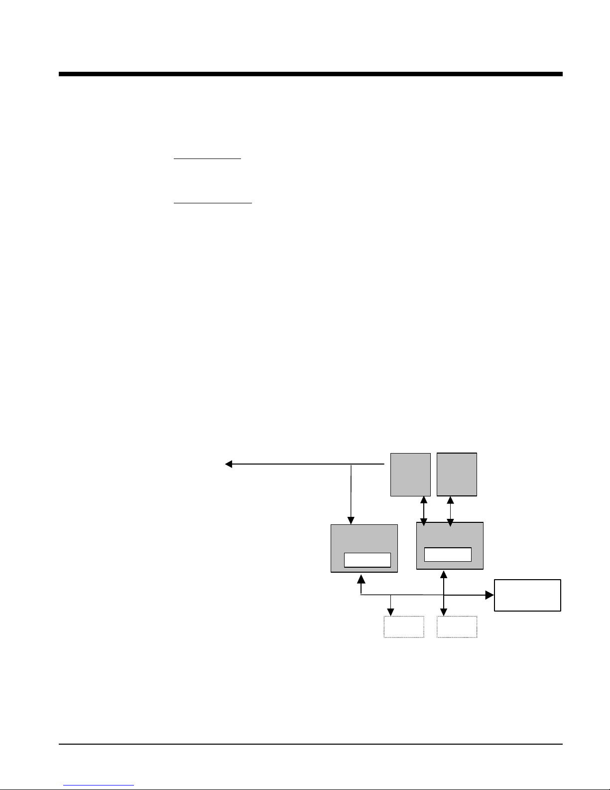
Control Architecture
Figure 1, Major Control Components
BACnet MS/TP
BACnet IP
BACnet Ethernet
LonTalk
Chiller A
RS485/LON/Ethernet
Solid
State
Starter
EXV
OM AGSB-5 5
Unit
Controller
4x20 LCD
RS485
pLAN
(future)
Circuit #1
Controller
4x20 LCD
Other Circuit
Controllers
(future)
Page 6

Component Description
Unit and Circuit Controller Descri ption
Terminology and Definitions
Accumulator
The accumulator is an electronic “bank” that stores information relative to fan operation and
fan capacity required. It is the heart of the controller’s fuzzy logic feature. Various events
such as cooling load changes and ambient air temperature changes, add or subtract points in
the bank. When a certain number of points are accumulated, a fan will be started.
Active Setpoint
The active setpoint is the setting in effect at any given moment. This occurs on setpoints
that can be altered during normal operation. Resetting the chilled water leaving temperature
setpoint by one of several methods, such as return water temperature, is an example.
Condenser Saturated Temperature Target
The saturated condenser temperature target is calculated by first using the following
equation:
Sat condenser temp target raw = 0.833(evaporator sat temp) + 68.34
The “raw” value is the initial calculated value. This value is then limited to a range defined
by the Condenser Saturated Temperature Target min imum an d maxi mum set point s. These
setpoints simply cut off the value to a working range, and this range can be limited to a
single value if the two setpoints are set to the same value.
CPU Error
These are problems caused by a malfunction of the central processing unit.
Dead Band
The dead band is a set of values associated with a setpoint such that a change in the variable
occurring within the dead band causes no action from the controller. For example, if a
temperature setpoint is 44°F and it has a dead band of ± 2 degrees, nothing will happen until
the measured temperature is less than 42°F or more than 46°F.
Delta-T
Delta-T is a range of degrees of temperature. For example, a Start Up Delta-T of 5 degrees
means that the water temperature must be 5 degrees above the LWT setpoint before the start
signal is given.
Discharge Superheat
Discharge superheat shall be calculated for each circuit using the following equation:
Discharge Superheat = Discharge Temperature – Condenser Saturated Temperature
Error
In the context of this manual, “Error” is the difference between the actual value of a variable
and the target setting or setpoint.
Evaporator Approach
The evaporator approach is calculated for each circuit. The equation is as follows:
Evaporator Approach = LWT – Evaporator Saturated Temperature
6 OM AGSB-5
Page 7

EvapRecTimer
The evaporator recirculation timer establishes the length of time the chilled water pump will
run after the controller receives an enable signal and the Wait for Flow timer time out. This
period allows time for the chilled water to circulate sufficiently to determine if there is a
need for cooling.
EXV
Electronic expansion valve, used to control the flow of refrigerant to the evaporator,
controlled by the circuit microprocessor.
High Saturated Condenser – Hold Value
High Cond Hold Value = Max Saturated Condenser Value – 5°F
This function prevents the compressor from loading whenever the pressures approach
within 5 degrees of the maximum discharge pressure. The purpose is to keep the
compressor online during periods of possibly temporary elevated pressures.
Low OAT Start
Allows start attempts at low ambient temperatures.
High Saturated Condenser – Unload Value
High Cond Unload Value = Max Saturated Condenser Value – 3°F.
This function unloads the compressor whenever the pressures approach within 3 degrees of
the maximum discharge pressure. The purpose is to keep the compressor online during
periods of possibly temporary elevated pressures.
Low Pressure Hold Setpoint
The psi evaporator pressure setting at which the controller will not allow further compressor
loading.
Low/High Superheat Error
The difference between actual evaporator superheat and the superheat target.
LWT
Leaving water temperature. The “water” is any fluid used in the chiller circuit.
LWT Error
Error in the controller context is the difference between the value of a variable and the
setpoint. For example, if the LWT setpoint is 44°F and the actual temperature of the water
at a given moment is 46°F, the LWT error is +2 degrees.
LWT Slope
The LWT slope is an indication of the trend of the water temperature. It is calculated by
taking readings of the temperature every few seconds and subtracting them from the
previous value, over a rolling one minute interval.
Maximum Saturated Condenser Temperature
The maximum saturated condenser temperature allowed is calculated based on the
compressor operational envelope .
Mode
There are three possible operating modes for the unit: Some can be combined and then
selected by an external signal or from the keypad.
1. Cool, the compressors are under normal unloading and staging control and the
minimum LWT setpoint is 40°F. Cool with Glycol merely reduces the minimum LWT
to 30°F.
2. ICE, primarily controls the compressor at full load until the LWT setpoint is reached,
then shuts unit off.
3. Test, allows outputs to be actuated manually.
OM AGSB-5 7
Page 8

ms
Milli-second
OAT
Outside ambient air temperature
pLAN
Peco Local Area Network is the proprietary name of the network connecting the control
elements.
Refrigerant Saturated Temperature
Refrigerant saturated temperature is calculated from the pressure sensor readings for each
circuit. The pressure is fitted to an R-134a temperature/pressure curve to determine the
saturated temperature .
Slide
Slide is an abbreviation for the compressor slide valve, which determines the compressor
capacity. It is positioned by the controller such that to unload, it moves toward the main
rotor suction end and discharge gas is bypassed from the rotor discharge back to suction.
Slide Target, Slide Position
See page 14 for explanation of these terms.
SP
Setpoint
SSS
Solid state starter as used on McQuay screw compressors
Suction Superheat
Suction superheat is calculated for each circuit using the following equation:
Suction Superheat = Suction Temperature – Evaporator Saturated Temperature
Stageon/Stageup
Stage On or Stage Up is the act of starting a compressor or fan when another is still
operating. The two phrases are interchangeable and either one can be used depending on
the date of issue of the software. “Start” is the act of starting the first compressor or fan on
a unit.
Stageoff/Stagedown
Stage Off or Stage Down is the act of stopping a compressor or fan when another is still
operating. The two phrases are interchangeable and either one can be used depending on
the date of issue of the software. “Stop” is the act of stopping the last compressor or fan on
a unit.
VDC
Volts, Direct current, sometimes noted as vdc
VFD
Variable Frequency Drive, a device used to vary an electric motor’s speed.
Unit and Circuit Controller Description
Hardware Structure
The controllers are fitted with a 16-bit microprocessor for running the control program.
There are terminals for connection to the controlled devices (for example: solenoid valves,
expansion valves, chilled water pumps). The program and settings are saved permanently in
FLASH memory, preventing data loss in the event of power failure without requiring a
back-up battery. It also has optional remote communication access capability for a BAS
interface.
8 OM AGSB-5
Page 9
Each chiller has one unit controller and a cir cuit controller for each compressor circuit (two
or three depending on unit size). The controllers are connected and communicate via a
pLAN (local area network). The circuit controllers communicate with, and control the
operation of, the compressor's solid state starter and the circuit electronic expansion valve
(EXV).
Keypad
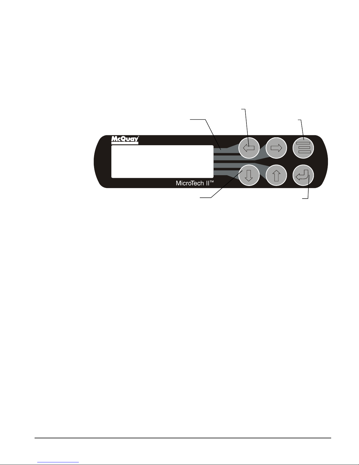
A 4-line by 20-character liquid crystal display and 6-button keypad is mounted on the unit
and compressor controllers.
Figure 2, Keypad
Key-to-Screen Pathway
Red Alarm Light
MENU Key
Air Conditioni ng
ALARM
<
VIEW
<
<
ARROW Keys (4)
SET
ENTER Key & Green Ru n Li ght
The four arrow keys (UP, DOWN, LEFT, RIGHT) have three modes of use.
1. Scroll between data screens in the direction indicated by the arrows (default mode).
2. Select a specific data screen in the menu matrix using dynamic labels on the right side
of the display such as ALARM, VIEW, etc. (this mode is entered by pressing the
MENU key). For ease of use, a pathway connects the appropriate button to its
respective label on the screen.
3. Change field values in setpoint programming mode as follows:
LEFT key = Default RIGHT key = Cancel
UP key = Increase (+) DOWN key = Decrease (-)
These four programming functions are indicated by one-character abbreviation on the right
side of the display. This programming mode is entered by pressing the ENTER key.
OM AGSB-5 9
Page 10
Control Operation
This section on MicroTech II control is divided into four subsections:
• Circuit Controller, explains the functions of the circuit controller, see page 10.
• Unit Controller, explains the functions of the unit controller, see page 24.
• Using the Controller, explains how to navigate through the menus and how to make
entries, see page 37.
• Screen Content, details the menu screen content and how to use them, see page 41.
Circuit Controller
Inputs/Outputs
Table 1, Analog Inputs
# Description Signal Source Range
1 Evaporator Pressure 0.5 - 4.5 VDC (NOTE)
2 Condenser Pressure 0.5 - 4.5 VDC (NOTE)
3 Liquid Pressure 0.5 - 4.5 VDC (NOTE)
4 Suction Temperature Thermistor (10k@25°C)
5 Discharge Temperature Thermistor (10k@25°C)
6 Liquid Temperature Thermistor (10k@25°C) -58 to 212°F
7 Slide Load Indicator 4 to 20 mA
8 Open
NOTE: Value at the converter board input. Value at the converter board output is 0.1 VDC – 0.9 VDC.
0 to 132 psi
3.6 to 410 psi
3.6 to 410 psi
-58°F to 212°F
-58° to 212°F
0 to 100%
These parameters are analog inputs to the circuit controller. They are used internally as
needed and are sent to the correct pLAN addresses for use by other controllers or displays.
Table 2, Analog Outputs
# Description Output Signal Range
1 Fan 1&2 VFD 0 to 10 VDC 20 to 60 Hz
2 Open
3 EXV Driver 0 to 10 VDC 0 to 6386 steps
4 Open
These parameters are analog outputs from this controller. The values are sent to the correct
pLAN addresses for use by other controllers or displays.
Table 3, Digital Inputs
# Description Signal Signal
1 Circuit Switch 0 VAC (Off) 24 VAC (Auto)
2 Open
3 Starter Fault 0 VAC (Fault) 24 VAC (No Fault)
4 VFD Fault 0 VAC (Fault) 24 VAC (No Fault)
Oil Differential
5
Pressure Switch
6 Mech High Pressure 0 VAC (Fault) 24 VAC (No Fault)
7 Low Pressure Switch 0 VAC (Fault) 24 VAC (No Fault)
8 Open
9 Oil Level Sensor 0 VAC (Fault) 24 VAC (No Fault)
10 Open
11 Open
0 VAC (Fault) 24 VAC (No Fault)
10 OM AGSB-5
Page 11
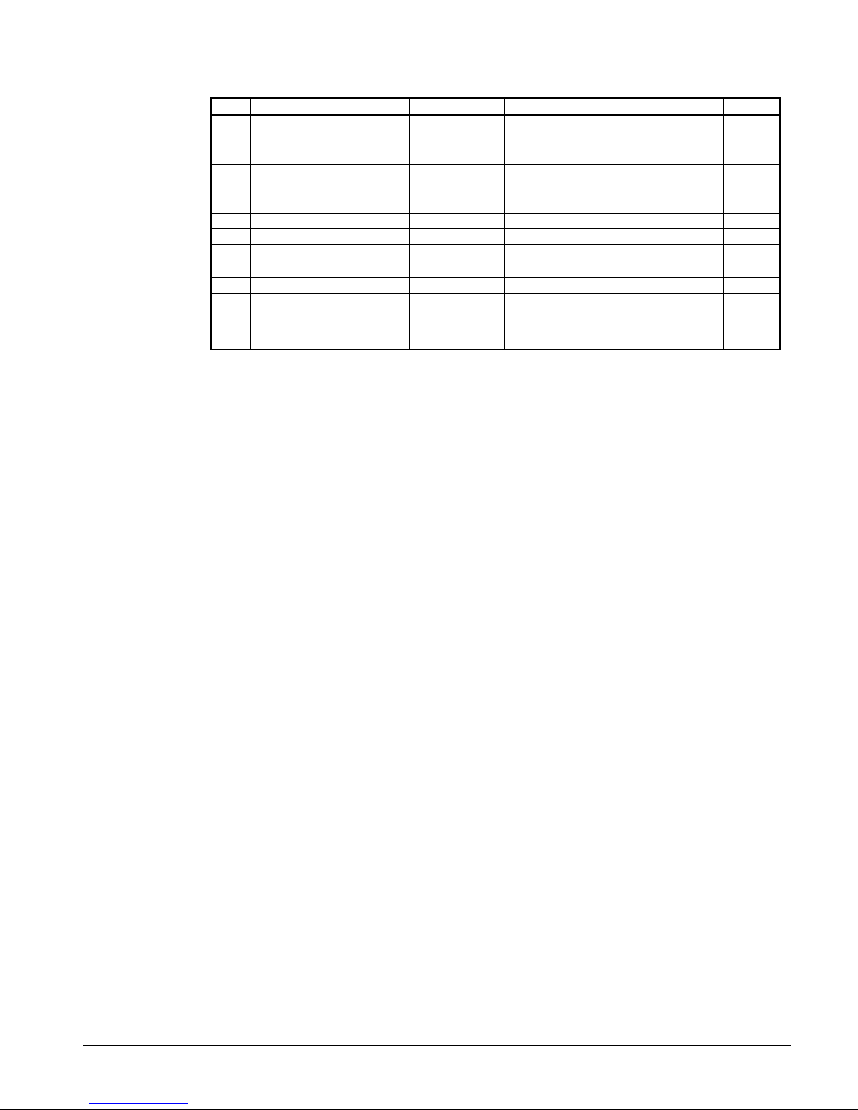
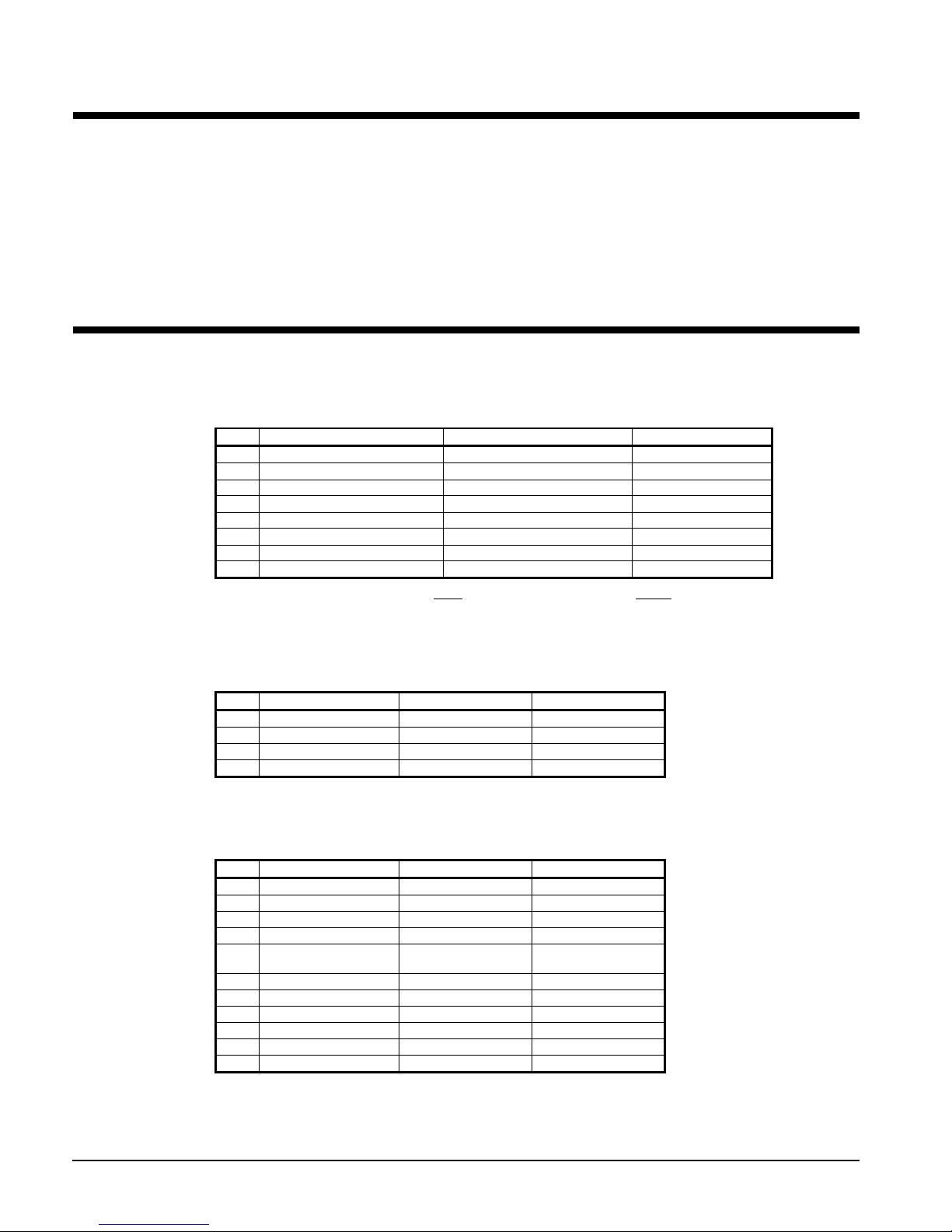
Table 4, Digital Outputs
# Description Load Output OFF Output ON Voltage
1 Compressor Starter Contact Relay Compressor off Compressor on 120
2 M1 Contactor (fan 1) Contactor Coil Fans off Fans on 120
3 M2 Contactor (fan 2) Contactor Coil Fans off Fans on 120
4 M3 Contactor (fan 3) Contactor Coil Fans off Fans on 120
5 M4 Contactor (fan 4) Contactor Coil Fans off Fans on 120
6 M5 Contactor (fan 5 & 6) Contactor Coil Fans off Fans on 120
7 Load/Unload Pulse S ol enoi d Hold l oad sl i de Move load slide 24
8 Load/Unload Select Relay Unload Load 24
9 M7 Contactor (fan 7 & 8) Contactor Coil Fans off Fans on 120
10 Oil Return Line Solenoid Closed Open
11 Open
12 Open
13 EXV Close Signal Contact
EXV Follows
0 – 10 VDC
EXV Closed,
Ignores 0 – 10
VDC
10
These parameters are digital outputs from this controller. Their values are sent to the correct
pLAN addresses for use by other controllers or displays.
Setpoints
The following parameters are remembered during power off, are factory set to the
Default value, and can be adjusted to any value in the Range column.
The PW (password) column indicates the password that must be active in order to
change the setpoint. Codes are as follows:
O = Operator, password is 100
M = Manager
Entering a Password
The password is located in the unit controller only and can be found at SET, UNIT SPS on
the last menu conveniently located so that you can scroll up one menu to access the
Password Enter Screen.
OM AGSB-5 11
Page 12
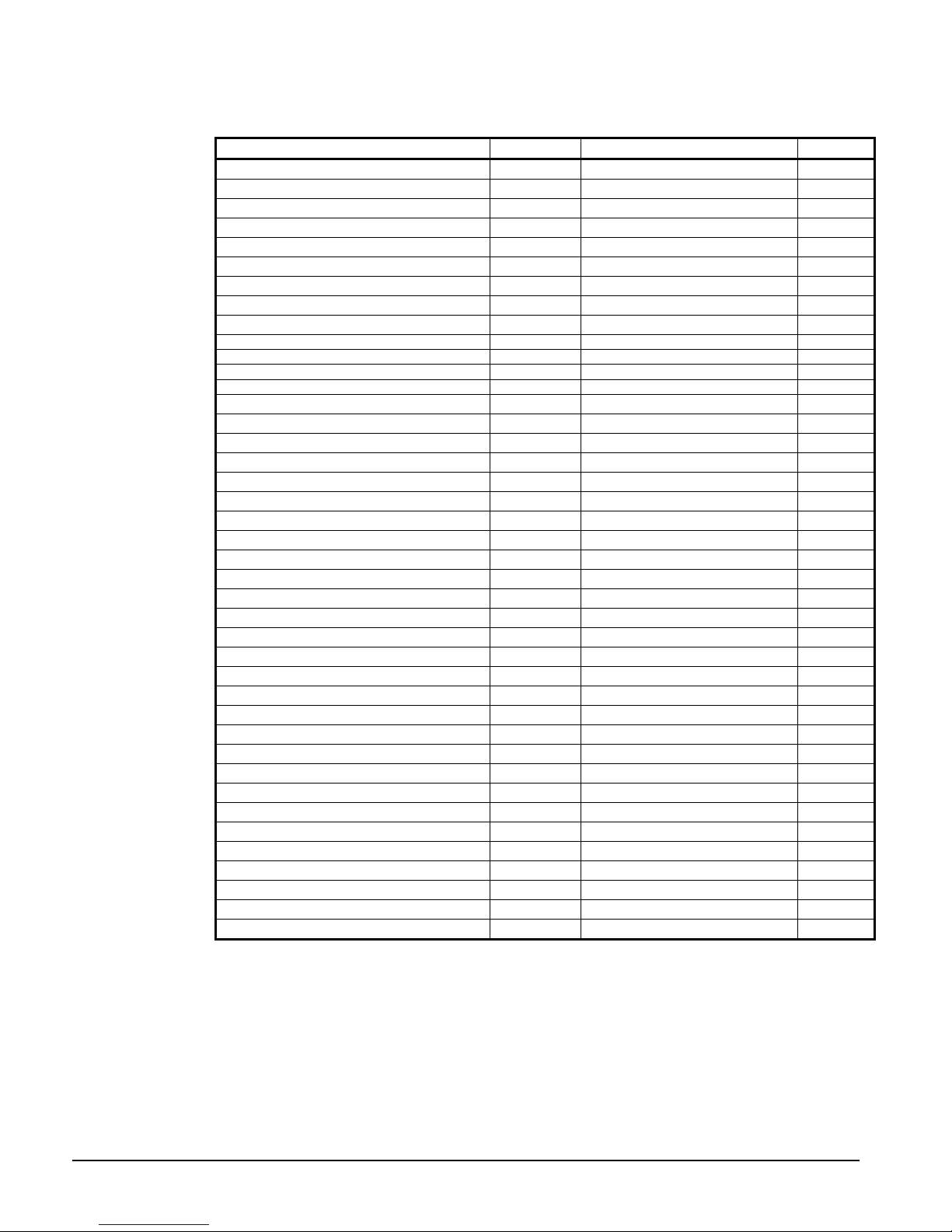
Table 5, Circuit Controller Setpoints
Description Default Range PW
Compressor
Circuit mode Enable Disable, Enable, Test M
Slide control Auto Auto, Manual M
Slide position 0 0-100% M
Compressor Size 205 205,220,235 M
Clear Cycle Timers N o No, Yes M
Maximum Slide Target 100.0 0-100.0% M
EXV
EXV control Auto Auto, Manual M
Manual EXV position 0 0-6386 M
Pre-open timer 60 20-120 sec M
Service Pumpdown No No, Yes M
Fans
Fan VFD enable Yes No, Yes M
Number of fans 6 6,8 M
Saturated Condenser Temp Target 110.0 90. 0 – 130.0 oF M
Stage 1 Up Deadband 5.0 1.0-20.0 oF M
Stage 2 Up Deadband 8.0 1.0-20.0 oF M
Stage 3 Up Deadband 10.0 1.0-20.0 oF M
Stage 4 Up Deadband 12.0 1.0-20.0 oF M
Stage 1 Down Deadband 8.0 1.0-20.0 oF M
Stage 2 Down Deadband 7.0 1.0-20.0 oF M
Stage 3 Down Deadband 6.0 1.0-20.0 oF M
Stage 4 Down Deadband 5.0 1.0-20.0 oF M
VFD Max Speed 100% 90 to 110% M
VFD Min Speed 25% 20 to 60% M
Forced FanTrol™ 1
Forced FanTrol™ 2
Forced FanTrol™ 3
Sensors
Evap pressure offset 0 -10.0 to 10.0 psi M
Cond pressure offset 0 -10.0 to 10.0 psi M
Liquid pressure offset 0 -10.0 to 10.0 psi M
Suction temp offset 0 -5.0 to 5.0 deg M
Discharge temp offset 0 -5.0 to 5.0 deg M
Liquid temp offset 0 -5.0 to 5.0 deg M
Slide Minimum Position 0 -15 to 15% M
Slide Maximum Position 0 -15 to 15% M
1 1-8 M
2 1-8 M
3 1-8 M
12 OM AGSB-5
Page 13

Circuit Operating Mode
The circuits on the chiller can each be individually enable or disabled. Test mode on each
circuit can also be entered independent of the all other circuits. With the circuit switch on,
the circuit mode setpoint offers settings of either Enable or Disable. This simply allows the
circuit to be disabled through a keypad setting.
Cool Mode
When the chiller is in COOL mode, capacity of the compressor is adjusted to maintain
leaving water temperature at the Active LWT setpoint while balancing the load between
running circuits. Load balance offset, LWT error, and LWT slope are used to calculate a
change in slide position.
ICE Mode
Ice mode is designed to have the compressors run at full load until the LWT setpoint is
reached, then shut off until the next ice making cycle starts. ICE settings are made in the
unit controller.
In ICE mode, the compressor capacity is increased at the maximum rate continuously until
reaching the maximum slide position. Load balancing, LWT error, and LWT slope are
ignored. Low and high pressure events are disabled.
An adjustable Start-to-Start Ice Delay Timer will limit the frequency with which the chiller
may start in ICE mode. The timer starts when the first compressor starts while the unit is in
ICE mode. While this timer is active, the chiller cannot restart in ICE mode. The time
delay is user adjustable.
The Ice Delay Timer may be manually cleared to force a restart in ICE mode. A set point
specifically for clearing the ICE mode delay is available. In addition, cycling the power to
the controller will clear the I ce Delay Timer .
Circuit Test Mode
The circuit test mode allows manual testing of all controller outputs. Entering this mode
requires the following conditions.
• Circuit Switch = OFF
• Technician password active
• Circuit Mode setpoint = TEST
A test menu can then be selected to allow activation of the outputs. It is possible to switch
each digital output ON or OFF and set the analog outputs to any value. Upon entering the
test mode, all outputs will always default to the OFF state. Upon leaving the test mode, all
outputs will automatically reset to the OFF state.
Compressors cannot be started in TEST mode.
Slide Position
Each compressor will estimate its slide load percentage from the present value of the slide
load indicator. The percentage is based on the 4-20mA signal from the slide load indicator
and varies somewhat by compressor size. A load percentage value of 0 corresponds to mA
Low signal; a percentage value of 100 corresponds to the mA High signal shown in Table 6.
This information is located on the View Cir Status (1) menu. It shows slide position and
slide target.
Table 6, Slide Valve Position
Compressor
Size
205
220
235
NOTE: See the Physical Data tables in IMM AGSB-60 for unit compressor sizes.
mA Low mA High
4.94 14.6
4.62 17.0
4.32 19.4
OM AGSB-5 13
Page 14

Slide Calibration Procedure
The slide is calibrated in the factory before shipment but may have to be recalibrated in the
field, especially if relevant slide parts have been replaced.
Slide Position is a relative capacity adjustment from 0.0%(Min load) to 100.0%(Max Load).
There are two MicroTech II controller readings that apply to the indicator, Slide Target and
Slide Position. It is important to understand the difference between these. The Slide Target
is the value in which the controller uses to display the calculated prediction of slide
position. This value represents the destination or goal of pulsing the load and unload
solenoids. The slide target is used for direction of control for all load and unload operations,
including alarm limit events. When putting a circuit in Manual mode, the slide target is the
value that you will be adjusting and the controller will load or unload the chiller to match,
with in about 3%, the target entered with the current slide position value. The second value
is the Slide Position (Pos) this is the slide position value which is the 4-20mA reading
received from the position indicator. These values can be viewed at the circuit controller on
screen “VIEW CIR STATUS (1)”.
A slide target of 0.0% is fully unloaded and the unload solenoid will be constantly
energized. A slide target of 100.0% means that the chiller is at full load and the load
solenoid is continually energized. The chiller will regulate the slide position to infinite steps
between 0% and 100% by pulsing the appropriate solenoid. Facing the front of the
compressor the solenoid on the left is for load (oil vent) and the solenoid on the right is for
unload (oil feed). In Circuit Enable mode (normal operation) the controller makes decisions
to move the Slide target, the calculated value, and pulses the proper solenoid in order to
keep the actual and the target position with in a few percent.
1. It is recommended that the circuit to be calibrated is near normal operating
temperatures, although a preliminary calibration before first starting the compressor is
acceptable, as long as the value is verified soon after compressor shuts down. Note that
it requires sufficient oil pressure to unload the compressor while it is running, and may
load up due to lack of oil pressure. When the compressor is not running there is a large
spring that forces the compressor unloaded, therefore in the off state you have the best
opportunity for verifying an accurate calibration at minimum slide position.
2. On the Circuit controller first verify what your current slide target is at screen “View
Circ Status (1)” and then go to screen “SET COMP SPs (2)” to switch circuit into
manual slide control. Note: Some inhibit limits will be ignored but all alarm limits are
still active.
3. Slowly take the circuit either to 0% or 100% load. When the slide target is at either 0%
or 100%, you may want to verify that the corresponding coil is energized.
4. On the circuit controller scroll all the way to the right, then the calibration and offsets
menu. Scroll down until you see “SET SENSOR OFFSET (3)”. You will see an
adjustment for Min Load and Max Load and on the bottom line you will see the value of
the actual slide position indicator. Add offset until value is within +/-.5%.
5. Repeat until all circuits have both positions calibrated with in +/-.5%.
Note: The Slide Indicator Transducers may vary a considerable amount with temperature
change, and therefore they need to be calibrated at typical running temperatures.
14 OM AGSB-5
Page 15

Compressor Control
Multiple Compressor Staging
This section defines which compressor is the next one to start or stop. The next section
defines when
Functions
1. Can start/stop compressors according to an operator-defined sequence.
2. Can start compressors based on the least number of starts (run hours if starts are equal)
and stop on most run hours.
The above two modes can be combined so that there are two or more groups where all
compressors in the first group are started (based on number of starts/hours) before any in the
second group, etc. Conversely, all compressors in a group are stopped (based on run hours)
before any in the preceding group, etc.
Required Parameters
1. Sequence number setpoint for all compressors. Possible settings = (1-3). Compressors
will start in the specified order. Default operation sequence is 1 for all compressors
(meaning they will start based on number of starts). That is, if all are 1s, the controller
will look at number of starts and run-hours
2. Maximum Number of compressors ON setpoint. Possible settings = (1-3).
3. Number of starts for all compressors.
the start, or stop, is to occur.
4. Number of run hours for all compressors.
5. Status of all compressors (Available/Unavailable, Pumping down, Running, etc.).
Multiple Compressor Start/Stop Timing
This section defines when a compressor is to start, or stop, and the scenario for doing so.
Starting
Staging up, no compressors on the unit are running:
The first compressor can start when the LWT is more than the sum of the active LWT
setpoint and the Startup Delta-T. For example, with default settings, the active setpoint
would be 44°F and the startup delta would be 10 degrees F. In this case, the LWT must be
greater than 54°F. This is a necessary, but may not be a sufficient, condition for starting the
first compressor. The Startup Delta-T is adjustable from 10 degrees down to 0 degrees F.
Staging up, at least one compressor is already running:
Additional compressors can start when the LWT is more than the sum of the active LWT
setpoint and the Stage Delta-T. With the default settings, the active setpoint is 44°F, and the
Stage Delta would be 2 degrees F. So, one necessary condition for staging an additional
compressor on is that the LWT must be higher than 46°F.
If in Cool Mode, an additional requirement is that all running compressors are running at
their maximum capacity, or at least 75% slide position and the Stage Up Delay Timer (5
minute default) has timed out. Also, a compressor is considered to be at its maximum
capacity if it is in an inhibit or unload situation due to low evaporator pressure, high
condenser pressure, or low discharge superheat. If a compressor is set for manual slide
control, or the slide target has reached the maximum allowed by the Max Slide setpoint, it
will also be flagged as being at maximum capacity.
OM AGSB-5 15
Page 16

Stopping
Staging down, at least two compressors running:
For staging off compressors, the LWT must be less than the active LWT setpoint minus the
Stage Delta-T. Based on default settings, the active setpoint would be 44°F, and stage delta
of 2 degrees F. So the LWT must be less than 42°F to stage off a compressor. This is a
sufficient condition to tr ig ger a stage down.
For 3 compressor units, the Stage Down Delay Timer must time out before the second lag
compressor will stage down, unless LWT minus Stage Down Delta-T is exceeded, or the
LWT rises above the setpoint.
Staging down, one compressor running:
With one compressor left running, the stage off requires that the LWT be less than the active
LWT setpoint minus the Stop Delta-T. With default settings, the active setpoint is 44°F, and
the Stop Delta is 3 degrees F, so the LWT must be less than 41°F to stage off the last
compressor. This is a sufficient condition to trigger a stage down.
History Storage
The number of starts and total compressor run hours is maintained in non-volatile memory
and can be viewed on the Unit Controller or corresponding Circuit Controller.
Compressor Capacity Control
Compressor capacity is determined by calculating a slide position target. Adjustment to the
slide target for normal running conditions occurs every 10 seconds. For loading, a
maximum change of 1% is allowed, and for unloading, a maximum change of 2% is
allowed. During alarm conditions, the slide target may be reduced to satisfy alarm limits.
The change to the target is calculated as follows.
Capacity Overrides – Limits of Operation
The following conditions override the automatic slide control when the chiller is in COOL
mode or ICE mode. These overrides keep the circuit from entering a condition in which it
is not designed to run. As previously noted, any compressor that is running with capacity
limits because of these conditions will be considered to be at full load in the compressor
staging logic. An important point to realize is that a particular chiller’s components are
designed for a specific range of capacity and chilled water flow. Varied conditions such as
high water temperature or low condenser pressure can cause higher refrigerant flow than the
chiller is designed to handle, therefore the chiller control may limit unit operation to
maintain system integrity at the highest compressor load possible.
Low Evaporator Pressure
If the compressor is running and the evaporator pressure drops below the Low Evaporator
Pressure-Hold setpoint, the compressor will not be allowed to increase capacity. The slide
position target will be limited to a maximum value equal to the target at the time the hold
condition was triggered. This limit will be active until the evaporator pressure reaches the
hold setpoint plus 2-psi.
If the compressor is running above minimum load capacity and the evaporator pressure
drops below the Low Evaporator Pressure-Unload setpoint, the compressor will begin
reducing capacity. The maximum allowed slide target will be adjusted down 5% every 5
seconds until the evaporator pressure rises above the Low Evaporator Pressure-Unload
setpoint. The slide target will then be limited to the current value until the evaporator
pressure rises to the unload setpoint plus 2-psi. If the pressure drops to the Unload Setpoint,
the EXV will switch to pressure control.
16 OM AGSB-5
Page 17

High Condenser Pressure
If the compressor is running and the condenser pressure rises above the High Lift Pressure
Hold setpoint, the compressor will not be allowed to increase capacity. The slide position
target will be limited to a maximum value equal to the target at the time the hold condition
was triggered. This limit shall be active until the condenser pressure drops 10 psi below the
hold setpoint.
If the compressor is running above minimum load capacity and the condenser pressure rises
above the High Condenser Pressure Unload setpoint, the compressor will begin reducing
capacity. The maximum allowed slide target will be adjusted down 5% every 5 seconds
until the condenser pressure drops below the High Condenser Pressure-Unload setpoint.
The slide target will then be limited to the current value until the condenser pressure drops
to 10 psi below the unload setpoint.
High Leaving Water Temperature
If the LWT is above 50°F, then the Max Slide is limited to 80% to avoid overloading.
Low Discharge Superheat
If the compressor is running, and the discharge superheat is less than 22oF, the compressor
will not be allowed to increase capacity. This limit will be active until the superheat is more
than 22
o
F.
If the compressor is running above minimum load capacity, and the discharge superheat is
less than 20
adjusted down 2% every 5 seconds, as long as the superheat remains below 20
o
F, then the compressor will begin reducing capacity. The slide target will be
o
F.
Maximum LWT Pulldown Rate
The maximum rate at which the leaving water temperature can drop is limited by the
Maximum Rate setpoint. A slope unload factor is used to reduce the slide target if the
pulldown rate exceeds the Maximum Rate setpoint.
Slope Unload Factor: Maximum Rate + LWT slope
If the pulldown rate is too fast, the slide adjustment will be made equal to the slope unload
factor.
Unit Capacity Overrides
Unit capacity limits can be used to limit total unit capacity in COOL and COOL w/
GLYCOL modes only. Multiple limits may be active at any time, and the lowest limit is
always used in the compressor capacity control.
These limits represent a limit on the unit capacity as a whole. Therefore, an estimate of the
current unit capacity is needed. Any circuit that is off is considered to be running at 0% of
its capacity. A running circuit is assumed to be running at a minimum of 20% capacity, and
the assumed capacity will very linearly from 20% to 100% as the slide position varies from
0% to 100%. The unit capacity is calculated using the following formula:
Unit Capacity = (Cir1 Capacity + Cir2 Capacity + Cir3 Capacity) / Number of Circuits
The estimated unit capacity and the active capacity limit are sent to all circuits for use in
compressor capacity contro l.
The active capacity limit values can be viewed at View Unit Status (2) and consist of the
following:
Soft Load
Soft Loading is a configurable function used to ramp up the unit capacity over a given time.
The set points that control this function are:
OM AGSB-5 17
Page 18

• Soft Load – (ON/OFF)
• Begin Capacity Limit – (Unit %)
• Soft Load Ramp – (seconds)
The Soft Load Unit Limit increases linearly from the Begin Capacity Limit set-point to
100%, over the amount of time specified by the Soft Load Ramp set-point. If the option is
turned off, the soft load limit is set to 100%.
Demand Limit
The maximum unit capacity can be limited by a 4 to 20 mA signal on the Demand Limit
analog input. This function is only enabled if the Demand Limit setpoint is set to ON. The
maximum unit capacity changes linearly from 0% (at 20 mA) to the 100% (at 0 mA).
Network Limit
The maximum slide load percentage of the compressor can be limited by a value sent
through a BAS network connection and stored in the Network Limit variable. This function
will be enabled if the control source is set to BAS.
ICE Mode Start Delay
In ICE mode there is a 12 hour delay from the time the unit shuts off until it may start again.
If the chiller is in ICE mode and the delay is active, the unit state will be Off and the unit
status will indicate this condition. The time left will also be displayed. While this delay is
active, the chiller may still start in cool mode.
If needed, the ice delay can be cleared using a setting found in the unit set points menu.
Pumpdown
When a circuit reaches a condition where the compressor needs to shut down normally, a
pumpdown will be performed. The slide target will automatically go to 0 while pumping
down, and the compressor will run until the pumpdown pressure has been reached, or the
pumpdown time has been exceeded. The Pumpdown Setpoint may need to be reduced if the
unit is running in the COOL w/ GLYCOL mode.
Service Pumpdown
If the option for a service pumpdown is enabled, then on the next pumpdown the pressure
setpoint will be 15 psi. The circuit will pumpdown to this pressure and shut off. When the
compressor has completed the service pumpdown, the setpo int is re set to No.
Manual Slide Control Mode
The slide position on each circuit can be controlled manually. A setting on the compressor
setpoints screen in each circuit controller allows the operator to select manual slide control.
On the same screen, a slide target can be selected from 0% to 100%.
Anytime a circuit is in manual slide control, it is considered to be at full load in the staging
logic. It also will not be considered a running compressor for load balancing purposes.
None of the capacity limits outlined above will apply in manual slide control, but all stop
alarms are still applicable.
Slide Positioning
Slide Load Indicator
Each compressor will estimate its slide load percentage from the present value of the slide
load indicator. The percentage is based on the 4-20mA signal from the slide load indicator.
See Table 6 on page 13 for the mA signal corresponding to slide position.
18 OM AGSB-5
Page 19

Load/Unload Select
The load/unload selector determines which solenoid will be pulsed for a change in capacity.
When unloading is required, the load/unload select output should be off. When loading of
the compressor is required, the output should be on.
Slide Pulse
The slide pulse output moves the compressor slide in order to reach the capacity reflected
by the slide position target. The output will pulse for 200 ms every 3 seconds until the slide
position is within a 3% deadband around the target.
Condenser Fan Control
The compressor must be running in order to stage its fans on.
VFD (Standard)
Condenser pressure trim control is accomplished using a variable frequency drive (VFD) on
the first two fans that turn on. This VFD control uses a proportional integral function to
drive the saturated condenser temperature to a target value by changing the fan speed. The
target value is normally the same as the saturated condenser temperature target setpoint.
The VFD will start the fans when the saturated condenser temperature goes above the
temperature target. Once the VFD fans are on, they will not shut off until the saturated
condenser temperature is less than the minimum saturated temperature plus 5 degrees F.
Stage up Compensation
In order to create a smoother transition when another fan is staged on, the VFD compensates
by slowing down initially. This is accomplished by adding the new fan stage up deadband
to the VFD target. The higher target causes the VFD logic to decrease fan speed. Then,
every 10 seconds, 0.5
condenser temperature target setpoint. This will allow the VFD to slowly bring the
saturated condenser temperature back down.
o
F is subtracted from the VFD target until it is equal to the saturated
Condenser Target
This logic is only used with VFD = Yes. Most applications will benefit from using the
default values. In the software versions previous to AGSU30101F, there was only one
setting for condenser target setpoint, with a default of 110°. Beginning with AGSU30101F
software there are two setpoints used to set a minimum (Min) and a maximum (Max) range
for the saturated condenser target. This can be found on the circuit controller at Set Fan
Sps(5). This will allow for a floating condenser target based on saturated evaporator
temperature. The default values of the minimum and maximum are both set to 110°
saturated condensing temperature. This will allow for the most stable unit operation.
Adjusting the Min or Max setpoint at each circuit controller will vary the condenser target
along a line determined by two points which are, 85° saturated condenser at 20° saturated
suction and 110° saturated condenser at 50° saturated suction. Note that the chiller system
is designed for specific refrigerant flow capacities, which may be exceeded by decreasing
the condenser target. The result will be at lower ambient temperatures, the chiller may
attain the maximum unit tonnage capacities while compressor loading will be limited on
low discharge superheat.
Fan Stages with VFD Option
The VFD option must always be enabled. The first two fans are controlled by the fan VFD.
This leaves 6 stages of FanTrol available with 8 fan circuits, and 4 stages available on 6 fan
circuits. Although fans 5/6 and 7/8 are controlled by one contactor each, more stages are
created by using virtual stages. See the table below:
OM AGSB-5 19
Page 20
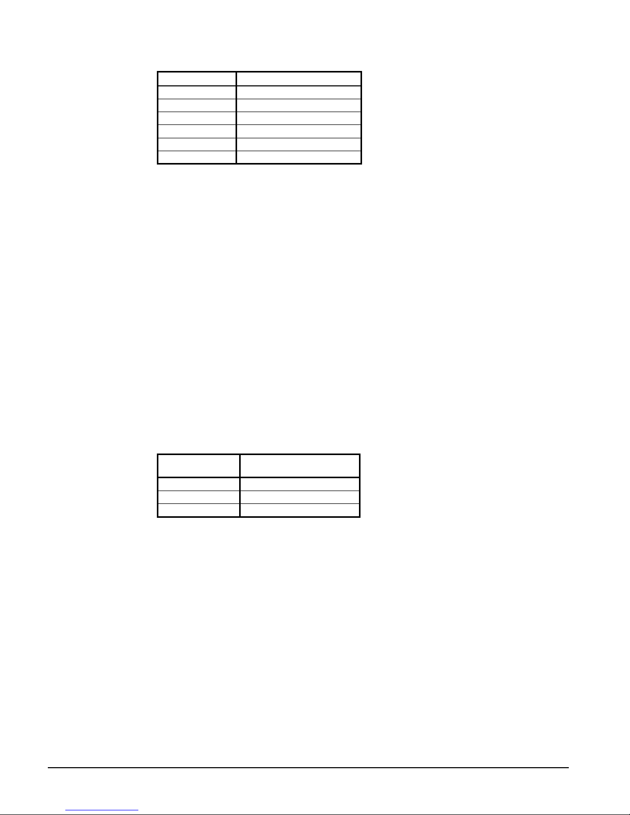
Table 7, Staging with VFD
Stage Fans On
1 1,2,3
2 1,2,3,4
3 1,2,4,5,6
4 1,2,3,4,5,6
5 1,2,3,5,6,7,8
6 1,2,3,4,5,6,7,8
Staging Up
There are four stage-up deadbands that apply to the FanTrol stages. Stages one through
three use their respective deadbands. Stage four to eight share the fourth stage-up
deadband.
When the saturated condenser temperature is above the Target + the active deadband, a
Stage Up error is accumulated.
The saturated condenser temperature must not be falling for a Stage Up accumulation to
occur.
Stage Up Error Step = Saturated Condenser Refrigerant temperature – (Target + Stage
Up Deadband)
The Stage Up Error Step is added to Stage Up Accumulator once every Stage Up Error
Delay seconds. When Stage Up Error Accumulator is greater than the Stage Up Error
Setpoint, another stage is added.
When a stage up occurs, or the saturated condenser temperature falls back within the Stage
Up deadband, the Stage Up Accumulator is reset to zero.
Forced Fan Stage At Start
Fans may be started simultaneously with the compressor based on outdoor ambient
temperature. When the compressor starts, a FanTrol stage is forced, based on the following
table.
Table 8, Forced Staging
Outside Air
Temperature
> 75oF Forced FanTrol 1 SP
> 90oF Forced FanTrol 2 SP
> 105oF Forced FanTrol 3 SP
Staging Down
FanTrol Stage At Start
There are four Stage Down deadbands. Stages one through three use their respective
deadbands. Stages four to eight share the fourth Stage Down deadband.
When the condenser saturated refrigerant temperature is below the Target – the active
deadband, a Stage Down error is accumulated.
Stage Down Error Step = (Target - Stage Down deadband) - Saturated Condenser
Refrigerant temperature
The Stage Down Error Step is added to Stage Down Accumulator once every Stage Down
Error Delay seconds. When the Stage Down Error Accumulator is greater than the Stage
Down Error Setpoint, another stage of condenser fans turned off.
When a stage down occurs, or the saturated temperature rises back within the Stage Down
deadband, the Stage Down Error Accumulator is reset to zero. The accumulator is also held
at zero after startup until either the outside ambient temperature is less than or equal to 75°F,
or the saturated condenser temperature is greater than the condenser target less the active
stage down deadband.
20 OM AGSB-5
Page 21

EXV Control
Three different expansion valve (EXV) control modes are used. Any time the EXV is not in
one of these control modes, it will be closed. For any of the control modes, the EXV
position is limited to a range based on the slide position target. The minimum setting
provides sufficient flow for motor cooling, the maximum flow limit helps prevent flood
back to the compressor. The table below shows the EXV range for each size compressor, at
mini mum and maximu m capa city. The mini mum and maximu m value s vary l inear ly wit h
slide position, defining a new EXV control range for every change in slide position.
Table 9, EXV Range
EXV Slide %
Min 0 250 250 250
Max 0 3000 3000 3000
Min 100 870 1080 1300
Max 100 3400 4200 5000
205mm 220mm 235mm
Based on the values in the above table, the EXV control range varies as shown in the figure
below. The shaded area is the control range.
Figure 3, EXV Control Range
Max EXV
@ 100%
Compressor Size
EXV Control Range
EXV
Steps
Max EXV
@ 0%
Min EXV
@ 100%
Min EXV
@ 0%
0
Slide Position (%)
100
1. Pre-Open
At the time of a start request, the EXV will perform a pre-open function. This is to provide
sufficient liquid refrigerant in the evaporator to avoid low pressure situations at startup.
During pre-open, the EXV will open to 3000 steps, while the saturated evaporator
temperature is less than the LWT. The EXV will move to 250 steps when the saturated
evaporator temperature is e qual to, or grea ter tha n, the LWT.
The EXV must be in the pre-open state for a time equal to the pre-open timer setpoint
before the compressor will start. This state may be skipped if the start request occurs, and
the evaporator saturated temperature is greater than LWT + 5°F. In this case, the
compressor would start and the EXV would go straight to pressure control.
2. Pressure Control
The EXV will be in pressure control mode after startup, and always when in the ICE mode.
In this mode, the EXV controls discharge superheat with adjustments to the evaporator
pressure target. A proportional integral function is used to keep the evaporator pressure at
the target.
OM AGSB-5 21
Page 22

The base pressure target is calculated using the following formula:
Base target = 2/3LWT – 8
The base target is limited to a range from the low pressure inhibit setpoint, plus 2 psi, up to
52 psi.
The pressure control target may be adjusted if the discharge superheat is not within an
acceptable range. If the superheat is less than 22°F, the base pressure target will be reduced
by a value equal to the low superheat error. If the superheat is more than 40°F, th e ba s e
pressure target will be increased by a value equal to the high superheat error. At any time,
the adjusted target pressure cannot go below the low pressure inhibit setpoint plus 2 psi, or
above 52 psi.
The EXV will transition from pressure control to subcool control when all of the following
are true:
• Discharge Superheat > 22°F for at least 3 minutes while in pressure control
• LWT <= 60°F
• Subcool > current base subcool value
• Unit mode = Cool (includes Available Modes: Cool w/ Glycol. Subcool control is not
used in Ice Mode)
The pressure target will ramp down when transition to pressure control occurs. The
pressure target will decrement 0.2 psi every second until it reaches the normal target. The
starting target is the current pressure at transition to pressure control, but is limited to a
maximum of 52 psi.
The EXV may transition from subcool control back to pressure control. This occurs when
the LWT is greater than 63°F , the unit mode is switched from Cool to Ice, or in F code, a
low evaporator pressure unload occurs. Starting with F code, when suction pressure drops
below the low evaporator pressure unload setpoint, the controller will switch from subcool
control to pressure control, until sufficient subcooling is established.
3. Subcool Control
After completing pressure control, the EXV transitions to the primary mode of operation,
subcool control. In this mode, subcooling is controlled by the EXV, with adjustments to the
subcool target based on discharge superheat. The base subcool target varies linearly from 5
degrees F to 20 degrees F as slide position changes from 0 to 100%.
The base subcool target value is adjusted when the discharge superheat is less than 22
degrees F, or greater than 40 degrees F. For every degree below the minimum, the subcool
target is adjusted up one degree. Similarly, for every degree above the maximum, the
subcool target is adjusted down one degree. The maximum offset to the base subcool value
is 15 degrees F, and the adjusted subcool target is limited to a minimum of 2 degrees F.
When the circuit initially enters subcool control, the subcool target is set to the current
subcool value less 2 degrees. This value may be above the normal 5 to 20 degree range.
The target subcool value is then reduced 0.1 degree every two seconds until it reaches the
calculated target value.
The EXV may transition from subcool control back to pressure control. This occurs when
the LWT is greater than 63°F or if the pressure drops to the LPUnload SP, while in subcool
control.
The EXV will transition from subcool control to pressure control if a low pressure unload
occurs. The normal rules to transition back to subcool control will apply.
22 OM AGSB-5
Page 23

Closed
Any time the EXV is not in pre-open, pressure control, or subcool control, it will be in a
closed state. At this time, the EXV position is 0 steps and the EXV close signal is active.
Manual EXV Control
The EXV position can be set manually. Manual control can only be selected when the
compressor is in the run state. At any other time, the EXV control setpoint is forced to auto.
When EXV control is set to manual, the EXV position is equal to the manual EXV position
setting. If set to manual when the compressor state transitions from run to another state, the
control setting is automatically set back to auto.
To verify EXV operation in an off state, see Unit Test Mode on page 28.
Evaporator Oil Return Line Control
The oil return solenoid shall be on any time the compressor is running and any of the
following occurs:
Slide position target < 60 AND Discharge superheat > 35
Slide position target >= 60 AND Discharge superheat > 50
Oil Level input = open AND Discharge superheat > 35
Oil Heater Control
The oil heater shall be on when the compressor is not running AND the oil level input is
closed.
Interstage Injection
The purpose is to control the discharge temperature at low LWT conditions when the
dischare temperature is high. The interstage injection is activated when the compressor is
running AND the discharge temperature rises above 185°F. The output shall be turned off
when either the compressor is no longer running, OR the discharge temperature drops below
170°F.
OM AGSB-5 23
Page 24

Unit Controller
Inputs/Outputs
The following parameters are analog inputs to this controller. They are used internally as
needed and are sent to the correct pLAN addresses for use by other controllers or displays.
Table 10, Unit Analog Inputs
# Description Signal Source Range
1 Outdoor Ambient Temperature Thermistor (10k@25°C)
2 Demand Limit 4-20 mA Current 25-100 %RLA
3 Chilled Water Reset 4-20 mA Current
4 Leaving Evaporator Water Temperature Thermistor (10k@25°C)
5 Entering Evaporator Water Temperature Thermistor (10k@25°C)
The following parameters are digital inputs to this controller. They are used internally as
needed and are sent to the correct pLAN addresses for use by other controllers or displays.
The status of digital inputs can be viewed on Unit Status screen #4, on the unit controller
only.
Table 11, Unit Digital Inputs
# Description Signal Signal
1 Unit Switch 0 VAC (Stop) 24 VAC (On)
2 Remote Switch 0 VAC (Stop) 24 VAC (Start)
3 Evaporator Water Flow Switch 0 VAC (No Flow) 24 VAC (Flow)
4 Mode Switch 0 VAC (Cool) 24 VAC (Ice)
5 Open
6 Open
-58°F to 212°F
0 to10 degrees
60°F max inlet
-58°F to 212°F
-58°F to 212°F
The following parameters are digital outputs from this controller. Their values are sent to
the correct pLAN addresses for use by other controllers or displays. The status of digital
outputs can be viewed on Unit Status screen #4, on the unit controller only.
Table 12, Unit Digital Outputs
# Description Load Output OFF Output ON
1 Open
2 Evaporat or Water Pump 1 Pump Contactor Pump OFF Pump ON
3 Evaporat or Water Pump 2 Pump Contactor Pump OFF Pump ON
4 E vap Heat ers Heater relay Heater OFF Heater ON
5 Open
6 Open
7 Open
8 Alarm Remote Alarm No Alarm Stop Alarm
Setpoints
At power-up, the slave node checks if the master node is operational and if so, it sets its
copy of the setpoint equal to the master’s. Otherwise, the setpoint remains unchanged.
During normal operation, any time the master setpoint changes, the slave is updated as well.
The PW (password) column indicates the password that must be active in order to change
the setpoint. Codes are as follows:
O = Operator, M = Manager
24 OM AGSB-5
Page 25

Table 13, Unit Controller Setpoints
Description Default Range PW
Unit
Unit Enable OFF OFF, ON O
Unit Mode COOL
Control source SWITCHES SWITCHES, KEYPAD, NETWORK O
Available Modes COOL
Cool LWT
Ice LWT
Startup Delta-T 10.0 degF 0.0 to 10.0 degF O
Stop Delta-T 3.0 degF 0.0 to 3.0 degF O
Stage Delta-T 2.0 degF 0.0 to 3.0 degF O
Max Pulldown 0.5 degF/min 0.1-5.0 degF/min M
Evap Recirculate 30 sec 0 to 300 sec M
Evap pump control #1 Only #1 Only, #2 Only, Auto M
LWT Reset Type NONE NONE, RETURN, 4-20mA, OAT M
Max Reset 0.0 degF 0.0 to 20.0 degF M
Start Reset Delta-T 10. 0 degF 0.0 to 20.0 degF M
Soft Load On On, Off M
Begin Capacity Limit 40% 20-100% M
Soft Load Ramp 20 min. 1-60 min. M
Demand Limit no No,yes M
Low Ambient Lock
Ice Time Dlay 12 hrs. 1-23 hrs. M
Clear ice Timer No No, Yes M
Display Units
Language English English M
BAS Protocol NONE
Ident number 1 0=200 M
Baud Rate 19200 1200, 2400, 4800, 9600, 19200 M
Compressors
Sequence # Cir 1 1 1-3 M
Sequence # Cir 2 1 1-3 M
Sequence # Cir 3 1 1-3 M
Max Compressors On 3 1-3 M
Start-start timer 20 min 15-60 minutes M
Stop-start timer 5 min 3-20 minutes M
Number of Compressors 2 2-3 M
Pumpdown pressure 25.0 psi 10.0-30.0 psi M
Pumpdown time limit 120 sec 0-180 sec M
Light Load Stage Down Point 255 20-50% Slide M
Light Load Stage Down Delay 3 min. 3-30 min. M
Stage Up Delay 5 min. 0-60 min. M
Alarms
Low Evap Pressure-Unload 28 psi 0 to 45 psi M
Low Evap Pressure-Hold 30 psi 0 to 45 psi M
Low Oil Level Delay 120 s ec 10-180 sec M
High Oil Press Diff Delay 15 sec 0-60 sec M
Min Lift Delay 30 s ec 10-120 sec M
Low Subcooling 5 degF 0 to 10 degF M
High Discharge Temperature
Evaporator Water Freeze
Evap Flow Proof 3 sec 3 to 120 sec M
High Lift Delay 5 sec. 0-30 sec. M
Sensors
OAT sensor offset 0 degF -5.0 to 5.0 degF M
LWT sensor offset 0 degF -5.0 to 5.0 degF M
EWT sensor offset 0 degF -5. 0 t o 5.0 degF M
44. 0°F 25.0(40.0) to 60.0 °F
25.0°F 20.0 to 38.0°F
55°F
°F, psi °F, psi
200° F
36 °F 15(34) to 42 °F
COOL, COOL w/Glycol,
ICE w/Glycol, TEST
COOL, COOL w/Glycol, COOL/ICE
w/Glycol, ICE w/Glycol, TEST
35-70 degF M
NONE, BACnet, LonWorks,
CAREL, MODBUS, N2
150 to 200 F M
O
M
O
O
M
M
M
These parameters are remembered during power off, and are factory set to the Default value.
OM AGSB-5 25
Page 26

Automatic Adjust ed Limits
The following setpoint ranges will be adjusted based on selected options.
Table 14, Evaporator Leaving Water Temperature Range
Mode Range
Unit Mode = Cool
Unit Mode = Cool w/Glycol, Ice, Ice w/ Glycol
Table 15, Evaporator Freeze Temperature Range
Mode Range
Unit Mode = Cool
Unit Mode = Cool w/Glycol, Ice, Ice w/ Glycol
Table 16, Low Evaporator Pressure Inhibit
Mode Range
Unit Mode = Cool 30 to 45 Psig
Unit Mode = Cool w/Glycol, Ice w/ Glycol 15 to 45 Psig
Table 17, Low Evaporator Pressure Unload
Mode Range
Unit Mode = Cool 28 to 45 Psig
Unit Mode = Cool w/Glycol, Ice w/ Glycol 15 to 45 Psig
40 to 60°F
20 to 60°F
34 to 42°F
15 to 42°F
Table 18, Low Ambient Lockout Temperature Range
Fan VFD Range
Fan VFD = N
Fan VFD = Y
35– 60°F
0 – 60°F
Unit Enable
Enabling and disabling the chiller is controlled by the Unit Enable Setpoint with options of
OFF and ON. The Unit OFF input (unit On/Off switch), field installed Remote stop switch,
keypad entry, or BAS request can alter this setpoint providing the correct control source
setpoint is selected. T he Control Source Setpoint determines which sources can change the
Unit Enable Setpoint with options of SWITCHES, KEYPAD, or NETWORK.
Changing the Unit Enable Setpoint can be accomplished according to Table 19 on page 27.
NOTE: An “x” indicates that the value is ignored.
Set Unit Setpoints Screen #1 (shown below) shows three fields “Enable”, “Mode” and
“Source.”
Unit Setpoints
SET UNIT SPs (1)
Enable=On
Mode= COOL
Source = KEYPAD
The Enable field is for use with Source = Keypad only, to enable and disable the chiller
through the key pad, ignoring any other control inputs including unit and pumpdown
switches and BAS controls.
26 OM AGSB-5
Page 27

1. The Mode field is an informational display, showing the active control mode of the
chiller. It is used as an input only when the source is set to keypad, only then can this
field be changed manually.
2. The Source field has three options, “SWITCHES” (default), “KEYPAD”, and “BAS
NETWORK”.
a. Switches source is used when there is no BAS interface
used. This allows the unit switches to function as pumpdown and shut down
switches for the circuit. This option is used with applications using the remote
start/stop input and not using a BAS interface.
b. Keypad source is used to override BAS or remote start/stop
commands. This would be used for servicing only.
c. BAS Network source would be used for those applications
using “MODBUS”, “BACNET”, or “LON” communications through a building
automation system. BAS Protocol is set at Set Unit Setpoints item #11.
Table 19, Unit Enable Settings
Unit On/Off
Switch
OFF x x x x OFF
x SWITCHES OFF x x OFF
ON SWITCHES ON x x ON
ON KEYPAD x OFF x OFF
ON KEYPAD x ON x ON
ON NETWORK x x OFF OFF
ON NETWORK OFF x x OFF
ON NETWORK ON x ON ON
Control Source
Setpoint
Remote
Stop Switch
Key-pad
Entry
BAS
Request
Unit
Enable
All methods of disabling the chiller, except for the unit switch, will cause a normal
shutdown of any running circuits. Any time the unit switch is used to disable the chiller, all
running circuits will shut down immediately, without pumping down.
Shutdown by the unit switch without going through the pumpdown cycle is undesirable and
should only be used for an emergency shutdown or for disabling the unit after both circuits
have gone through a normal shutdown.
Unit Mode Selection
The overall operating mode of the chiller is set by the Unit Mode Setpoint with options of
COOL, COOL w/Glycol, ICE w/Glycol, and TEST. The system switch must be off (unit
not running) to change the mode of operation.
Available Modes setpoint: usually set during initial setup and determines the operational
modes available at any time with options of:
• COOL, cooling only operation, with setpoints available for normal water temperatures.
• COOL w/Glycol, cooling only operation, allows lower setpoints than COOL.
• COOL/ICE w/Glycol, allows cooling and ice mode operation, switchable by a remote
digital signal, by the network or through the keypad.
• ICE w/Glycol, ice mode only, i.e., full load operation until LWT setpoint is reached.
• TEST
OM AGSB-5 27
Page 28

SET UNIT SPs (2)
Available Modes = COOL
Select w/Unit Swt Off
The setpoint can be altered by the keypad, BAS, and Mode input. Changes to the Unit
Mode Setpoint are controlled by two additional setpoints.
• Control Source Setpoint: Determines the source that can change the Unit Mode
Setpoint with options of KEYPAD (pCO
2
), NETWORK, or SWITCHES.
When the Control source is set to KEYPAD, the Unit Mode stays at its previous setting until
changed by the operator. When the Control source is set to BAS, the most recent BAS
mode request goes into effect even if it changed while the Control source was set to
KEYPAD or DIGITAL INPUTS.
Changing the Unit Mode Setpoint can be accomplished according to the following table.
NOTE: An “x” indicates that the value is ignored.
Table 20, Unit Mode Settings
Control Source
Setpoint
x x x x COOL COOL
x x x x COOL w/Glycol COOL w/Glycol
SWITCHES OFF x x COOL/ICE w/Glycol COOL w/Glycol
SWITCHES ON x x COOL/ICE w/Glycol ICE w/Glycol
KEYPAD x COOL w/Glycol x COOL/ICE w/Glycol COOL w/Glycol
KEYPAD x ICE w/Glycol x COOL/ICE w/Glycol ICE w/Glycol
NETWORK x x COOL COOL/ICE w/Glycol COOL w/Glycol
NETWORK x x ICE COOL/ICE w/Glycol ICE w/Glycol
x x x x ICE w/Glycol ICE w/Glycol
x x x x TEST TEST
Remote
ICE Mode
Switch
Keypad Entry
BAS
Request
Available Modes
Setpoint
Resultant Unit
Mode
The Remote ICE Mode Switch (usually a time clock) is a field installed option and is used
to switch from ice mode operation at night to cooling mode operation during the day. This
requires that the Control Source be set to SWITCHES, which in this case refers to the
Remote ICE Mode Switch.
There are really only three operational modes for the unit, although they can be used in
combination:
1. COOL, the unit unloading and compressor staging is controlled by the Active LWT
Setpoint. COOL w/ Glycol is a special case of this mode, providing for lower setpoint
ranges.
2. ICE, the unit runs with all compressors fully loaded until the LWT (set for making ice)
is reached, and the unit shuts off. The Ice Delay Timer can be set to prevent restarting
until the next ice making cycle.
3. TEST, manually energize outputs.
Unit Test Mode
Before beginning you must have the Manager password active. Note: To put each circuit
controller in test mode, you do not have to put the unit controller into test mode, therefore
you may allow one or more circuits to operate while in test mode on another circuit.
28 OM AGSB-5
Page 29

Circuit Controllers:
Be sure the pumpdown switch is in the off position. Press the Menu button (the top far right
button with three horizontal lines on it) on the circuit controller. Press the button that
corresponds to “SET”, then press “COMPRESSOR SPs”. Now press the down arrow
button once. Now that you are on the proper screen (SET COMP SPs (2)) you may push the
enter button to go into Change Values Mode for that screen.
You will now see the cursor blinking on the first line, also there will be a “D”, “C”, “+” and
“-” down the right side of the screen. Press the corresponding “+” or “-” button to scroll
through the menu options. You will see “Enable”, “Disable” and “Test”. To select “Test”,
press the enter button. Press the enter button until the cursor scrolls to the top left corner of
the screen on to the Menu title. Now scroll to the right to the last menu, this menu is the
“Test Circuit” menu. This menu was added when you entered “Test” in the Circuit Mode
field.
“Test Circuit” item #1 is for digital outputs for the fan contactor outputs. The unit is
equipped with fan VFD and fan outputs 1 and 2 will not function. The VFD fans will be
tested later. Press the enter button to go into change values mode. Continue to press enter
until you reach the output you would like to turn on, then press the “+” or “-” turn the
output on or off. Check that each fan is rotating in the proper direction, and does not have
excessive vibration.
“Test Circuit” item #2 is for digital outputs for Slide indicator. You will see a selection to
choose the slide pulse direction, with the options of “Load” (left coil) or “Unload”(right
coil). Then there is a selection to turn the pulse on or off. Choose “on” for the “Pulse” field
and then you can toggle between Load or Unload, checking the corresponding coil to see if
it energizes.
“Test Circuit” item #3 is for digital outputs for the Evaporator oil return line solenoid and
for the EXV close output. Turn the “Oil Return” on and check that the evaporator oil return
line solenoid is energizing. It is located on the base rail behind the suction line connection
to the compressor.
“TEST CIRCUIT” item #4 is for analog outputs for the fan VFD and the EXV. Here you
can ramp up the VFD by adjusting the frequency in the VFD field or manually open and
close the EXV. The EXV operation may be verified by observing operation through the
sight glass on the side of the valve body. Note: Unlike the digital outputs, you must hit
enter for the analog outputs to react to your change.
Unit Controller:
At the main menu select “SET”, then select “UNIT SPs”, scroll down 1 screen to screen #2
on the “SET UNIT SPs” screen. You will see “Available Modes”. Change the mode to
“TEST”. (Note: this will disable all running circuits.) Now scroll all the way to the right on
the unit test screen, there is only one screen. Verify the “Alarm Out” output at J15-NO8.
Verify the evap heaters are on by checking the amps on the appropriate wires. Verify the
evaporator pump outputs and wiring by turning the pump outputs on and off.
Note: When the service test is completed, remember to take both the unit and each of the
circuit controllers out of “Test” Mode and back into “Enable.”
OM AGSB-5 29
Page 30

Evaporator Pump State Control
The state-transition diagram shown below controls operation of the evaporator pump.
Figure 4, Evaporator Pump Control
Power ON
[Unit State=OFF
LWT > Freeze sp]
OR
[OAT low
All Comp State=OFF
LWT>70 F]
AND
RUN
AND
AND
OFF
[Unit
LWT > Freeze sp]
OR
[OAT low
All CompState=OFF
LWT>70 F]
Flow OK for
Evap Recirc Time
State=
OFF
AND
AND
[Unit State = AUTO
NOT [OAT low AND LWT > 40 F
OR
LWT < Freeze
AND
AND
sp – 1.0 F
START
One of two pumps can be automatically selected based on run hours. The run-hour counters
are not visible. When in Auto, the pump with the least hours will start. The options are # 1
only, #2 only, Auto.
The pump output used will be determined by the Evap Pump Control setpoint. This setting
allows the operator to select either pump #1 or pump #2. The selected output will be ON if
the Evap State is set to START or RUN. Both outputs will be OFF if the Evap State is set to
OFF.
Evaporator Heater Control
Evaporator heaters are controlled by the unit controller. This output is turned on when the
evaporator LWT is less than the water freeze setpoint + 2
when the LWT is more than the freeze setpoint + 4 degrees F.
degrees F. The output is turned off
Leaving Water Temperature (LWT) Reset
The Active Leaving Water setpoint is set to the current Leaving Water Temperature (LWT)
setpoint, unless the unit is in COOL mode, and any of the reset methods below are selected.
The type of reset in effect is determined by the LWT Reset Type setpoint. The Active
Leaving Water variable is sent to all circuits for capacity control after the applicable reset is
applied.
Reset Type – NONE
The Active Leaving Water setpoint is set equal to the current LWT setpoint.
Reset Type – RETURN
The return water temperature adjusts the Active Leaving Water setpoint. When the chiller
mode = COOL, the Active Leaving Water setpoint is reset using the following parameters:
1. Cool LWT setpoint
2. Max Reset Delta-T setpoint
3. Start Reset Delta-T setpoint
4. Evap Delta-T
30 OM AGSB-5
Page 31

Reset is accomplished by changing the Active Leaving Water setpoint from the Cool LWT
setpoint to the Cool LWT setpoint + Max Reset setpoint as the EWT – LW T (Evap Delta-T)
varies from the Start Reset Delta-T setpoint to 0.
Figure 5, Return Water Reset Conditions
Return Reset
Cool LWT+Max Reset
(54)
Active
LWT
o
F)
(
Max Reset
(10)
Cool LWT Set-Point
(44)
0
Start Reset Delta T
Evap Delta T (oF)
Reset Type – 4-20 mA Input Signal
The Active Leaving Water setpoint is adjusted by the 4 to 20 mA reset analog input.
Parameters used:
1. Cool LWT setpoint
2. Max Reset setpoint
3. LWT Reset signal
Reset is 0 if the reset signal is less than or equal to 4 mA. Reset is equal to the Max Reset
Delta-T setpoint if the reset signal equals or exceeds 20 mA. The amount of reset will vary
linearly between these extremes if the reset signal is between 4 mA and 20 mA.
Figure 6, External Reset Conditions
LWT Reset (Cool mode)
(temperatures are examples only)
(54.0°F)
Max Reset Delta T
(10.0°F)
Cool LWT Set-Point
(44.0°F)
OM AGSB-5 31
0 ma
4 ma
20 ma
Page 32

Reset Type – Outside Air Temperature (OAT)
O
A
A
The Active Leaving Water setpoint is reset based on the outdoor ambient temperature.
Parameters used:
1. Cool LWT setpoint
2. Max Reset setpoint
3. OAT
Reset is 0 if the outdoor ambient temperature is greater than 75°F. From 75 down to 60°F
the reset varies linearly from no reset to the max reset at 60°F. At ambient temperatures less
than 60°F, reset is equal to the Max Reset setpoint.
Figure 7, Outside Air Reset
T Reset
Cool LWT+Max Reset
(54)
ctive
LWT
o
(
F)
Max Reset
(10)
Cool LWT Set-Point
(44)
60
OAT (oF)
75
32 OM AGSB-5
Page 33

Alarms and Events
Situations may arise that 1) require some action from the chiller, or that 2) should be logged
for future reference. A condition that causes a shutdown and requires manual reset is known
as a stop alarm. Other conditions can trigger what is known as an event, which may or may
not require an action in response. All stop alarms and events are logged. The Unit
Controller and the Circuit Controller have different Alarms and Events.
Unit Stop (Shutdown) Alarms
This table identifies each unit stop alarm, gives the condition that causes the alarm to occur,
and states the action taken as a result of the alarm. (See the “Stop Alarms” section under the
Circuit Controller for a description of these alarms.)
The alarm output and red button LED are turned ON when any stop alarm occurs. They are
turned OFF when all alarms have been cleared.
Table 21, Unit Stop Alarms
Description Occurs When: Action Taken
No Evaporator Water Flow
(NOTE)
Evaporator Freeze Protect Evap LWT goes below evap freeze protect setpoint Rapid Stop
Leaving Evaporator Water
Temperature Sensor Fault
Outside Air Temperature
Sensor Fault
pLAN Failure No other controller found on the pLAN for 60 seconds Rapid Stop
NOTE: Beginning with this software version, two automatic resets per day (beginning at 12:00 am)
are allowed on the flow loss alarm. The Unit State remains on Auto and the evaporator will go back
to Start, waiting for flow.
Evap Pump State = RUN AND Evap Flow Digital Input
= No Flow for time > Flow Proof SP
Sensor shorted or open Rapid Stop
Sensor shorted or open Normal Shutdown
Rapid Stop
Unit Events
The following events only generate a warning message to the operator. Chiller operation is
not affected. They are logged in the Event Log with a time stamp.
Table 22, Unit Events
Description Occurs When: Action Taken Reset
Entering Evaporator Temperature
Sensor Fault
Sensor is open or
shorted
Cannot use return water
temperature control
Automatic
Circuit Stop (Shutdown) Alarms
The following table identifies each circuit stop alarm, gives the condition that causes the
alarm to occur, and states the action taken because of the alarm. All stop alarms require
manual reset. Rapid stop alarms do not initiate a pumpdown before shutting off. All other
alarms will initiate a pumpdown. The occurrence of a circuit stop alarm only affects the
circuit on which it occurred.
OM AGSB-5 33
Page 34

Table 23, Circuit Stop Alarms
Description Occurs When: Action Taken
No Pressure at Start
Low Evaporator Pressure
High Lift Pressure
Mechanical High Pressure Digital Input 6 = Open Rapid Stop
Below Minimum Lift Pressure
High Discharge Temperature Temp > High Discharge Temperature SP Rapid St op
Low Oil Level
High Oil Pressure Difference
Starter Fault (Note) Digital Input 3 = Open Rapid Stop
Evaporator Press. Sensor Fault Sensor shorted or open Rapid Stop
Condenser Press. Sensor Fault Sensor shorted or open Rapid Stop
Liquid Line Pressure Sensor Fault Sensor shorted or open Pumpdown
Discharge Temp. Sensor Fault Sensor shorted or open Pum pdown
Liquid Line Temp. Sensor Fault Sensor shorted or open Pumpdown
Slide Position Sensor Fault Sensor shorted or open Pumpdow n
Evap or Cond pressure< 7 psi when Compressor Start
Requested
[Freezestat trip OR Evaporator Press < 0 psi OR Low
Pressure Sw Open] AND Compressor State = Run
Cond Sat Temp > Max Sat Cond Value for a period
exceeding the setting of the High lift Delay timer
Cond Press < Min Sat Cond Value for time > Min Lift
Delay SP
DI9 = Open for Time greater than Low Oil Level Delay
+ the Low Oil Level Event has occurred in the past
hour
Digital Input 5 = Open for time greater than High
Press Diff Delay SP
Start Aborted,
Circuit Locked Out
on Manual Reset
Rapid Stop
Rapid Stop
Pumpdown
Rapid Stop
Rapid Stop
NOTE: As long as starter communication is functioning, power data will be displayed and starter
faults will be indicated. Some starter faults are self-clearing in the starter itself. Alarms triggered by
these faults will be allowed to self-clear twice per day. The third will trigger a manual reset in the
controller requiring it to be cleared via the active alarm screens on the unit controller. Alarms using
this logic are:
Current Imbalance Cu rrent low Phase Loss Phase Reversal
Voltage High Voltage Low No Starter Transition Other Starter Faults
Some starter faults never auto-clear in the starter. They can be clearedvia the Active Alarm screens
on the unit controller or on the starter itself. Alarms using this logic are:
High Current Trip Ground Fault High Motor Temperature
Evaporator Freezestat
Freezestat logic allows the circuit to run for varying times at low pressures. The lower the
pressure, the shorter the time the compressor can run. This time is calculated as follows:
Freeze error = Low Evaporator Pressure Unload – Evaporator Pressure
Freeze time = 60 – 6.25 x (Freeze error), limited to a range of 10-60 seconds
When the evaporator pressure goes below the Low Evaporator Pressure Unload setpoint, a
timer starts. If this timer exceeds the freeze time, then a freezestat trip occurs. If the
evaporator pressure rises to the unload setpoint or higher, and the freeze time has not been
exceeded, the timer will reset.
The following two values are designed to keep the compessor in its design operating
envelope.
Maximum Saturated Condenser Value
If Sat Evap Temp < 32 then
Max sat cond value = 155 + 1.588(Sat Evap Temp – 32)
If [Sat Evap Temp >= 32 AND Sat Evap Temp < 40] OR Circuit State = Pumpdown then
Max sat cond value = 155
If Sat Evap Temp >= 40 AND Sat Evap Temp < 55 then
Max sat cond value = 155 – 0.667(Sat Evap Temp – 40)
If Sat Evap Temp >=55 then
Max sat cond value = 145
34 OM AGSB-5
Page 35

Minimum Saturated Condenser Value
If Sat Evap Temp < 35, then
Min sat cond value = 73
If Sat Evap Temp >= 35 and < 55, then
Min sat cond value = (6/5)(Sat Evap Temp – 35) + 73
If Sat Evap Temp >= 55 then
Min sat cond value = 97
Circuit Events
The following events do not cause compressor shutdown but limit operation of the circuit in
some way as described in the Action Taken column.
Table 24, Circuit Events
Description Occurs When: Action Reset
Low Evaporator
Pressure - Hold
Low Evaporator
Pressure - Unload
High Lift Pressure
- Hold
High Lift Pressure
- Unload
Subcooling Low
Discharge
Superheat Low
Oil Level Low
Failed Pumpdown
Suction Temp.
Sensor Fault
VFD Fault VFD option enabled and Digital Input 4 = Open Pumpdown Automatic
Power Loss While
Running
Pressure < Low Evap Pressure - Hold SP
Pressure < Low Evap Pressure -Unload SP Unload
Pressure > High Sat Cond - Hold Value
Pressure > High Sat Cond - Unload Value Unload
EXV = Pressure Control AND Subcool < Low
Subcool SP OR EXV = Subcool Control AND
Subcool < (the lowest of the Low Subcool SP
and SC target – 0.5
EXV Control = Pressure Control AND Disc SH
< Min SH Setpoint for 10 minutes
DI9 = Open for Time greater than Low Oil Level
Delay AND more than one hour since last
Circuit state = pumpdown for more than the
Sensor shorted or open None
Circuit controller is powered up after losing
power while compressor was running
o
F) for longer than 5 min.
occurrence
Pumpdown Time SP
Inhibit
loading
Inhibit
loading
None
Pumpdown
and stop
Rapid stop Comp state = off
Stop N/A
Delay start of
compressor
Evap Press rises above
(SP + 2 psi)
Evap Press rises above
(Hold SP + 2 psi)
Cond Press drops below
(Hold Value – 10
Cond Press drops below
(Unload Value – 10
Subcool > setpoint or
Comp state = off
Comp state = off
Sensor Problem
corrected
N/A
o
F)
o
F)
High Saturated Condenser – Hold Value
High Cond Hold Value = Max Saturated Condenser Value – 5oF
High Saturated Condenser – Unload Value
High Cond Unload Value = Max Saturated Condenser Value – 3oF
Alarm and Event Logging
Alarm Logging
When an alarm occurs, the alarm type, date, and time are stored in the active alarm buffer
corresponding to that alarm (viewed on the Alarm Active screens) and also in the alarm
history buffer (viewed on the Alarm Log screens). The active alarm buffers hold a record of
all current alarms. The active alarms can be cleared by pressing the Enter key when the end
of the list has been reached by scrolling. Active alarms may be cleared only if a password is
active.
Beginning with this version, the BAS can clear the flow loss alarm, evaporator water freeze
alarm and pLAN failure, regardless of what other alarms are active.
OM AGSB-5 35
Page 36

A separate alarm log stores the last 25 alarms to occur. When an alarm occurs, it is put into
the first slot in the alarm log and all others are moved down one, dropping the last alarm. In
the alarm log, the date and time the alarm occurred are stored, as well as a list of other
parameters. These parameters include unit state, OAT, LWT, and EWT for all alarms. If the
alarm is a circuit alarm, then the circuit state, refrigerant pressures and temperatures, EXV
control state, EXV position, slide position, and number of fans on are also stored.
To view alarms, activate the manager password, press Menu on the unit controller, then
select Alarm (left arrow), then select Active or Log.
Event Logging
An event log similar to the alarm log holds the last 25 events to occur. When an event
occurs, it is put into the first slot in the event log and all other entries are moved down one,
dropping the last event. Each entry in the event log includes an event description, as well as
the time and date of the occurrence. No additional parameters are logged for events.
To view events, press Menu on the unit controller, then select Alarm (left arrow), then scroll
left to Event Log. See menu matrix on page 40.
36 OM AGSB-5
Page 37

Using the Controller
d
ght
4x20 Display & Keypad
Layout
The 4-line by 20-character/line liquid crystal display and 6-key keypad for both the circuit
controller and unit controller is shown below.
Figure 8, Display (in MENU mode) and Keypad Layout
Air Conditioni ng
Key to Screen Pathway
Left Arrow Key and
Red Alarm Light
ALARM
<
VIEW
<
<
SET
ARROW Keys (4)
MENU Key
ENTER Key an
Green Comp.
Run Li
Note that each ARROW key (except the down arrow) has a pathway to a line in the display.
Pressing an ARROW key will activate the associated line when in the MENU mode.
Arrow Keys
The four arrow keys (UP, DOWN, LEFT, RIGHT) have three modes of use.
1. Scroll between data screens as indicated by the arrows (default mode).
2. Select a specific data screen in a hierarchical fashion using dynamic labels on the right
side of the display (this mode is entered by pressing the MENU key).
3. Change field values in edit mode according to the following table:
LEFT Default (D)
RIGHT Cancel (C)
UP Increment (+)
DOWN Decrement (-)
These four edit functions are indicated by one-character abbreviations on the right side of
the display (this mode is entered by pressing the ENTER key).
Getting Started, Navigating-Press the MENU key to get started. The navigating
procedures are the same for both the unit controller and the circuit controller
MENU Key
The MENU key is used to switch between the MENU mode as shown in Figure 8 and the
SCROLL mode as shown in Figure 9. The MENU mode is basically a shortcut to specific
groups of menus used for checking ALARMS, for VIEWING information, or to SET
setpoint values. The SCROLL mode allows the user to move about the matrix (from one
menu to another, one at a time) by using the four ARROW keys.
.
OM AGSB-5 37
Page 38

When in the MENU mode (as shown in Figure 8), pressing the LEFT ARROW key will
select the ALARM menus, the RIGHT ARROW key will select the VIEW menus and the
UP key the SET menus. The controller will go the next lower menu in the hierarchy, and
then other menus can be accessed by using the ARROW keys. Pressing the MENU key
from any menu screen will automatically return to the MENU mode as shown in Figure 8.
Another way to navigate through the menus is to press the MENU key when in the MENU
mode (as above). This will switch the controller to the SCROLL mode. The controller will
automatically go to the first screen as shown below (the upper-left menu on the menu matrix
shown in Table 25 on page 40). From there, the four ARROW keys can be used to scroll
up, down, or across to any other menu.
Figure 9, Display (in SCROLL Mode) and Keypad Layout
Air Conditioni ng
MENU Key
VIEW UNIT ST ATUS
Unit = COOL
Compr. #1/#2=OFF/OFF
Evap Pump = RUN
ARROW Keys (4)
ENTER Key
ENTER Key
Pressi ng the E NTER key c hange s the functi on of t he ARROW keys to t he edit ing fun ction
as shown below:
LEFT key, Default
RIGHT key, Cancel
, changes a value to the factory-set default value.
, cancels any change made to a value and returns to the original
setting.
UP key, Increment
DOWN key, Decrement
, increases the value of the setting.
decreases the value of a setting.
These four edit functions are indicated by one-character abbreviation on the right side of the
display (this mode is entered by pressing the ENTER key).
Most menus containing setpoint values have several different setpoints shown on one menu
screen. When in a setpoint menu, the ENTER key is used to proceed from the top line to
the second line and on downward. The cursor will blink at the entry point for making a
change. The ARROW keys (now in the edit mode) are used to change the setpoint as
described above. When the change has been made, press the ENTER key to enter it.
Nothing is changed until the ENTER key is pressed.
For example, to change the chilled water setpoint:
1. Press MENU key to go to the MENU mode (see Figure 8).
2. Press SET (the UP Key) to go to the setpoint menus.
3. Press UNIT SPs (the Right key) to go to setpoints associated with unit operation.
4. Press the DOWN key to scroll down through the setpoint menus to the third menu which
contains Evap LWT=XX.X°F.
38 OM AGSB-5
Page 39

5. Press the ENTER key to move the cursor down from the top line to the second line in
order to make the change.
6. Use the ARROW keys (now in the edit mode as shown above) to change the setting.
7. When the desired value is achieved, press ENTER to enter it and also move the cursor
down.
At this point, the following actions can be taken:
1. Change another setpoint in this menu by scrolling to it with the ENTER key.
2. Using the ENTER key, scroll to the first line in the menu. From there the ARROW keys
can be used to scroll to different menus.
Security
All setpoints on the unit controller, as well as the circuit controllers, are protected using
passwords that provide OPERATOR and MANAGER levels of access to changeable
parameters. The operator password is 100.
Entering Passwords
Passwords can be entered using the ENTER PASSWORD screen on the unit controller,
which is the last screen in the Unit SPs column. The password is entered by pressing the
ENTER key, scrolling to the correct value with the UP and DOWN arrow keys, and pressing
ENTER again. The longer a key is held down, the faster it will increment. The entered
password is not shown after the enter key is pressed. The operator password is 100.
Once the correct password has been entered, the ENTER PASSWORD screen indicates
which password is active (none, operator, or manager). If the wrong password is entered, a
temporary message will appear so stating. If no valid password is active, the active
password level displays “none”.
Entering an incorrect password while a password is active will render that password
inactive. Entering a valid password that is not the same as the active password will result in
the active password level being changed to reflect the new password level.
Editing Setpoints
After a valid password has been entered at the unit controller, setpoints on the circuit
controllers and the unit controller can be changed. If the operator attempts to edit a setpoint
for which the necessary password level is not active, no action will be taken.
Once a password has been entered, it remains valid for 60 minutes after the last key-press
on the unit controller.
Clearing Alarms
Alarms are cleared at the unit controller as long as any password level is active. If the user
attempts to clear an alarm while no password is active, then the controller will automatically
go to the ENTER PASSWORD screen. The user can then enter a password normally, and
scroll back to the active alarm column to clear the active alarm(s). Clear alarms by pressing
and holding ENTER for 5 seconds.
To clear an alarm, go to the unit controller Alarm, Active Menu. Scroll down to the last
alarm listed. The screen will note “No More Alarms”. Press and hold Enter for five
seconds to clear alarms. If there are no active alarms, the red Alarm light will be off and
alarms status will clear from the unit and circuit controllers.
OM AGSB-5 39
Page 40

Unit Controller Menus
Various menus are shown in the controller display. Each menu screen shows specific
information. In some cases menus are used only to view status of the unit, in some cases
they are used for checking alarms, and in some case they are used to set the setpoint values
that can be changed.
The menus are arranged in a matrix of screens across a top horizontal row. Some of these
top-level screens have sub-screens located under them. The content of each screen and its
location in the matrix are shown in Table 25. A description of each menu begins on page 41.
The ARROW keys on the controller are used to navigate through the menus. The keys are
also used to change numerical setpoint values contained in certain menus.
As an alternate to selecting screens with the menu function, it is possible to scroll through
all of them with the 4 arrow keys. For this use, the screens are arranged logically in a
matrix as shown below.
Table 25, Unit Controller Menu S tructure
VIEW MENUS
VIEW
UNIT
STATUS
(1)
VIEW
UNIT
STATUS
(2)
VIEW
UNIT
STATUS
(3)
VIEW
UNIT
STATUS
(4)
Right half of
table
continued
from above
VIEW
UNIT
TEMP
(2)
VIEW
UNIT
TEMP
(2)
VIEW
CIR #1
(1)
VIEW
CIR #1
(2)
ALARM MENUS SET MENUS
EVENT
LOG
(1)
EVENT
LOG
(25)
VIEW
CIR #2
(1)
VIEW
CIR #2
(2)
ALARM
LOG
(1)
ALARM
ACTIVE
(1)
ALARM
LOG
(25)
ALARM
ACTIVE
(n)
VIEW
CIR #3
(1)
VIEW
CIR #3
(2)
VIEW
REFRG
CIR #1
(1)
VIEW
REFRG
CIR #1
(2)
VIEW
REFRG
CIR #1
(5)
Continued
SET UNIT
SPs (1)
SET UNIT
SPs
(2)
SET UNIT
SPs
(3)
SET UNIT
SPs
(4)
SET UNIT
SPs
(5)
SET UNIT
SPs
(6)
COMP SP
COMP SP
COMP SP
SET UNIT
SPs
(to 13)
VIEW
REFRG
CIR #2
(1)
VIEW
REFRG
CIR #2
(2)
VIEW
REFRG
CIR #3
(1)
VIEW
REFRG
CIR #3
(2)
VIEW
FANS
On-Off
(1)
VIEW
FANS
VFD
(2)
Right half of
table
VIEW
REFRG
CIR #2
(5)
SET
(1)
SET
(2)
SET
(3)
VIEW
REFRG
CIR #3
(5)
SET
ALARM
LMTS (1)
SET
ALARM
LMTS
(2)
SET
ALARM
LMTS
(3)
SET
ALARM
LMTS
(4)
SET
ALARM
LMTS
(5)
continued
SET
SENSOR
OFFSET
below
TEST
UNIT
40 OM AGSB-5
Page 41

Selection can then be made by using the LEFT/RIGHT keys to move between columns and
the UP/DOWN keys to move between rows. The menu structure allows the return to the
last screen viewed in each column. (This feature also applies to navigation using the
function keys.) As an example:
Attempts to scroll past the limits of the matrix are ignored.
Screen Definitions
The following section illustrates all the unit screens. The screens are listed in the order of
the matrix, starting from the upper-left.
View Unit Status
View screens are used to view the operation or status of the entire unit or individual circuit.
No settings are entered to these screens.
VIEW UNIT STATUS (1)
{Unit Status}
{Unit Mode}
Evap Pump= run
Unit Status will display one of the following:
Auto Off:Keypad Disable Off:Test Mode Auto:Wait for flow
Off:Ice Mode Timer Off:Remote Switch Auto:Wait for load Auto:Pumpdown
Off:All Cir Disabled Off:BAS Disable Auto:OAT Low
Off:Unit Alarm Off:Unit Switch Auto:Evap Recirc
VIEW UNIT STATUS (2)
Softload Limit=100.0
Demand Limit=100.0
Network Limit=100.0
The unit will limit loading to the lowest of the three limit values that are active.
VIEW UNIT STATUS (3)
Unit Capacity=xxx.x%
Ice Delay= XXh XXm
Ice delay will be visible only when unit mode is Ice.
VIEW UNIT STATUS (4)
1234
D.O. 0100
D.I. 1110
This screen gives the status of Digital Outputs 1 through 4 (D.O.) and Digital Inputs
1 through 4 (D.I.) as defined in Table 3 and Table 4.
0=Off, 1=On.
OM AGSB-5 41
Page 42

VIEW UNIT TEMP (1)
Evap LWT= XXX.X F
Evap EWT= XXX.X F
Active SP= XXX.X F
VIEW UNIT TEMP (2)
LWT Pulldn= 0.0 F/m
Evap Delta T=XX.X F
Outdoor Air=XXX.X F
NOTE: In the following VIEW CIRCUIT screens, the N field indicates which compressor
(#1, #2, etc.) is being viewed.
VIEW CIR N STATUS(1)
Off:Ready
Slide Position=000.0%
Slide Target=000.0%
Slide position and slide target are explained on page 18.
VIEW CIR N STATUS(2)
Hours = XXXXX
Starts = XXXXX
VIEW REFR CIR N (1)
Evap Press=XXX.X psi
Cond Press=XXX.X psi
Liq Press= XXX.X psi
VIEW REFRG CIR N (2)
Sat Evap= XXX.X °F
Sat Cond= XXX.X °F
Sat LiqLine= XXX.X°F
VIEW REFRG CIR N (3)
Suct Temp = XXX.X °F
Disc Temp = XXX.X °F
Liq Temp = XXX.X °F
VIEW REFRG CIR N (4)
Suct SH = XXX.X °F
Disc SH= XXX.X °F
Liquid SC= XXX.X °F
42 OM AGSB-5
Page 43

VIEW REFRG CIR N (5)
Evap Approach=XX.X°F
Cond Approach=XX.X°F
EXV position = XXXX
VIEW FANS (1)
Fans On, Cir 1= 0
Fans On, Cir 2= 0
Fans On, Cir 3= 0
VIEW FANS (2)
VFD Cir 1= 000.0 %
VFD Cir 2= 000.0 %
VFD Cir 3= 000.0%
ALARM and EVENT Screen Definitions
The alarms and events shown are examples only. Any possible alarm or event could be
shown. The alarm log and event log can show up to the 25 most recent occurrences.
EVENT LOG (1-25)
Event Description
hh:mm mm/dd/yy
ALARM LOG: (1-25)
Alarm Description
hh:mm:ss dd/mmm/yyyy
Parameters
ALARM ACTIVE
hh:mm mmm/dd/yy
Alarm Description
SET Screen Definitions
Setpoints shown are typical. Entries can be selected by scrolling through the available
possibilities. Setpoint ranges and choices are show in Table 13 on page 25.
Unit Setpoints
SET UNIT SPs (1)
Enable=On
Mode= COOL
Source = KEYPAD
OM AGSB-5 43
Page 44

SET UNIT SPs (2)
Available Modes = COOL
Select w/Unit Swt. Off
SET UNIT SPs (3)
Cool LWT = XX.X°F
Ice LWT – XX.X°F
The unit will only use the setpoint for the Mode selected.
SET UNIT SPs (4)
StartDelta= XX.X°F
StopDelta= XX.X°F
StageDelta= XX.X°F
The StartDelta is the number of degrees above the chilled water setpoint the water
temperature must rise for a compressor to start when no compressors are running. The
default is 1 0 degrees. F., the range i s 0 to 10 degrees. F. Settings below 10 degrees will
have the undesirable effect of increasing compressor cycling.
The StopDelta is the number of degrees below the chilled water setpoint the water
temperature must fall for the last compressor to stop.
The StageDelta is the number of degrees change in the chilled water to initiate a change in
staging.
SET UNIT SPs (5)
Max Pulldn=X.X°F/min
EvapRecTimer=XXX sec
Evap Pump= #1,#2, Auto
The controller can start either of two chilled water pumps or in the Auto mode will
automatically select the pump with the least run hours.
SET UNIT SPs (6)
Reset Type =none
MaxResetDT =XX.X°F
StrtResetDT=XX.X°F
See page 30 for reset options.
SET UNIT SPs (7)
Soft Load = Off
Begin Capacity= XXX%
SoftLoadRamp= XXmin
See page 17 for soft load and demand limit options.
44 OM AGSB-5
Page 45

SET UNIT SPs (8)
Demand Limit= Off
Low Amb Lock = XX.X°F
SET UNIT SPs (9)
Ice Time Delay=xxhrs
Clear Ice Timer=No
SET UNIT SPs (10)
CLOCK
dd/mmm/yyyy
hh:mm:ss
SET UNIT SPs (11)
Units = °F/psi
Lang = ENGLISH
Inch-Pound units of measure and English language are the only options available in this
software version.
SET UNIT SPs (12)
Protocol=
Ident Number=
Baud Rate=
SET UNIT SPs (13)
Enter Password:0000
Active Password
Level:none
Compressor (Circuit) Setpoints
SET COMP SPs (1)
Seq # Comp 1=
Seq # Comp 2=
Seq # Comp 3=
SET COMP SPs (2)
Max Comprs On = X
Start-Start = XXmin
Stop-Start = XXmin
OM AGSB-5 45
Page 46

SET COMP SPs (3)
# of Compressors=X
Pumpdn press=XX.X psi
Pumpdn time= XXX sec
SET COMP SPs (4)
Light Load Stage
Down Point=XX% slide
Stage Dn Delay=XXmin
SET COMP SPs (5)
Stg Up Delay= XXXsec
SET ALARM LMTS (1)
Low Evap Pressure
Hold=59.0 psi
Unload=58.0 psi
SET ALARM LIMITS (2)
LowOilDelay= XXX sec
HighOilDpDel=XXX sec
SET ALARM LIMITS (3)
MinLiftDel= XXX sec
Low Subcool= XX.X°F
High Disc Temp=XXX°F
SET ALARM LIMTIS (4)
Highlift Delay=XXsec
Evap Freeze= XX.X°F
Evap Flow Proof=XXX
SET SENSOR OFFSET
OAT= XX.X°F
Evap LWT= XX.X°F
Evap EWT= XX.X°F
46 OM AGSB-5
Page 47

TEST Screen Definitions
TEST UNIT
Alarm Out=Off
Evap Heaters=Off
Pump1=Off Pump 2=Off
Circuit Controller Menus
See "Using the Controller" on page 37 for information on how to navigate and use the menu
screens, as well as changing setpoints. As an alternate to selecting screens with the menu
function, it is possible to scroll through all of them with the 4 arrow keys. For this use, the
circuit controllers' screens are arranged logically in a matrix as shown below.
Table 26, Circuit Controller Screen Matrix
"TEST"
SCREENS
TEST
COMP
(1)
TEST
COMP
(2)
TEST
COMP
(3)
VIEW
UNIT (1)
VIEW
UNIT (2)
"VIEW" SCREENS "SET" SCREENS
VIEW
CIR
(1)
VIEW
CIR
(2)
VIEW
CIR
(3)
VIEW
CIR
(4)
VIEW
CIR
(5)
VIEW
CIR
(6)
VIEW
REFRG
(1)
VIEW
REFRG
(2)
VIEW
REFRG
(3)
VIEW
REFRG
(4)
VIEW
REFRG
(7
VIEW
FANS
(1)
VIEW
FANS
(2)
SET
COMP
SPs
SET
COMP
SPs (2)
SET
COMP
SPs (3)
SET
EXV SPs
(1)
SET
EXV SPs
(2)
SET
FANS
(1)
SET
FANS
(2)
SET
FANS(3)
SET
FANS
(4)
SET
FANS
(6)
SET
SENSOR
OFFSETS
(1)
SET
SENSOR
OFFSETS
(2)
SET
SENSOR
OFFSETS
(3)
Screen Definitions
VIEW Screens
Circuit VIEW screens are used to view the operation of a circuit's compressor, refrigerant
condition, EXV position, and fan operation. No settings are made on these screens.
VIEW UNIT (1)
Auto
Evap pump = Run
VIEW UNIT (2)
Evap LWT= XXX.X°F
Active SP= XX.X°F
LWT pulldn= XX.X°F/m
OM AGSB-5 47
Page 48

VIEW CIR STATUS (1)
Off:Ready
Slide Pos= XXX.X%
Slide Target= XXX.X%
VIEW CIR STATUS (2)
Hours = XXXXX
Starts = XXXXX
VIEW CIR STATUS (3)
Digital Outputs
Output Number
12345678910
0000000000
The digital outputs in menu 3 and 4 and the analog outputs in menu 5 are defined in Table 2
and Table 4 beginning on page 10. “0”= Off, “1”= ON.
Output Status
VIEW CIR STATUS (4)
Digital Outputs
11 12 13
000
VIEW CIR STATUS (5)
Analog Outputs
(volts X 100)
1=XXXX 3=XXXX
VIEW CIR STATUS (6)
Digital Inputs
123456789
000000000
VIEW REFRIGERANT (1)
Evap Press=XXX.X psi
Cond Press=XXX.X psi
Liq Press= XXX.X psi
VIEW REFRIGERANT (2)
Sat Evap = XXX.X °F
Sat Cond = XXX.X °F
Sat LiqLine= XXX.X °F
48 OM AGSB-5
Page 49

VIEW REFRIGERANT (3)
Suct Temp = XXX.X °F
Disc Temp = XXX.X °F
Liq Temp = XXX.X °F
VIEW REFRIGERANT (4)
Suct SH = XXX.X °F
Disc SH= XXX.X °F
Liquid SC= XXX.X °F
VIEW REFRIGERANT (5)
Evap Approach=XX.X °F
Cond Approach=XX.X °F
VIEW REFRIGERANT (6)
MaxCondSatT=XXX.X°F
EXV Control=Pressure
VIEW REFRIGERANT (7)
EXV Steps= XXXX
EXV ctrl range:
XXXX – XXXX steps
VIEW FANS (1)
VFD Speed= XXX.X%
Fans Running= X
VFD Target=XXX.X °F
VIEW FANS (2)
Target Sat T=XXX.X °F
Stage Up Err= XXX
Stage Dn Err= XXX
SET Screen Definitions
Compressor Setpoints
SET COMP SPs (1)
Clear Cycle Tmr=no
Comp Size=XXX
Max Slide= XXX.X%
Clearing the anti-recycle timer is a one-time event. If “yes” is selected, the timer will go to
zero but will then revert back to the original setting for any future occurrences.
OM AGSB-5 49
Page 50

SET COMP SPs (2)
Circuit Mode=Enable
Slide Control=auto
Slide Target= XXX.X%
SET COMP SPs (3)
Oil return
Max slide= XX.X%
Min Disch SH=XX.XoF
SET COMP SPs (4)
Motor FLA = NNNN amps
Mptpr RLA = NNNN amps
EXV Setpoints
SET EXV SPs (1)
EXV Control=auto
Manual EXV Pos=XXXX
Pre-open time=XXX sec
SET EXV SPs (2)
Min EXV= XXX steps
Service pumpdown=No
Fan Setpoints
SET FAN SPs (1)
Fan VFD = no
Number of fans = X
SET FAN SPs (2)
Stg Up Deadband(°F)
Stg1=XXX Stg3=XXX
Stg2=XXX Stg4=XXX
SET FAN SPs (3)
Stg Down Deadband(°F)
Stg1=XXX Stg3=XXX
Stg2=XXX Stg4=XXX
SET FAN SPs (4)
VFD Min speed= XXX%
VFD Max speed= XXX%
50 OM AGSB-5
Page 51

SET FAN SPs (5)
Cond Sat Temp Target
Setpoint= XXX.X °F
SET FAN SPs (6)
# Fans On At Startup
>75°F >90°F>105°F
XX X
Sensor Offsets
SET SENSOR OFFSET (1)
Evap Press= XX.X psi
Cond Press= XX.X psi
Liq Press= XX.X psi
SET SENSOR OFFSET (2)
Suct Temp= X.X F
Disch Temp= X.X F
Liq Temp= X.X F
SET SENSOR OFFSET (3)
Slide min pos=XX%
Slide max pos=XX%
Slide Pos=XXX.X%
Test
TEST CIRCUIT (1)
Fans:1=Off 2=Off
3=Off 4=Off
5/6=Off 7/8=Off
TEST CIRCUIT (2)
Slide Dir= Unload
Slide Pulse= Off
TEST CIRCUIT (3)
Oil Return= Off
EXV Closed= Off
TEST CIRCUIT (4)
Fan VFD Spd%= XXX.X
EXV Position=XXXX
OM AGSB-5 51
Page 52

Sequence of Operation
The following sequence of operation is typical for McQuay models AGS chillers. The
sequence may vary depending on the software revision or various options that may be
installed on the chiller.
Off Conditions
Power is supplied to each power panel located between condenser sections. Optionally, the
power may be supplied to a single power connection located in a terminal box on the base
of the unit.
With power supplied to the unit, 115 VAC power is applied through the control fuse F1 to
the compressor heaters (HTR1, HTR2, (and HTR3), evaporator heater, and the primary of
the 24V control circuit transformer.
Compressor heaters must be on for at least 12 hours
prior to start-up to avoid compressor damage.
The 24V transformer provides power to the MicroTech II controller and related components.
With 24V power applied, the controller will check the position of the front panel system
switch. If the switch is in the "stop" position, the chiller will remain off, and the display
will indicate the operating mode to be OFF: System Sw. The controller will then check the
pumpdown switches. If any of the switches are in the "stop" position, that circuit’s
operating mode will be displayed as OFF: PumpDwnSw. If the switches for both circuits
are in the "Stop" position, the unit status will display OFF: PumpdownSw’s. If the remote
start/stop switch is open the chiller will be OFF: RemoteSw. The chiller may also be
commanded off via communications from a separate communicating panel such a BAS
protocol interface. The display will show OFF: RemoteComm if this operating mode is in
effect. If an alarm condition exists which prevents normal operation of both refrigerant
circuits, the chiller will be disabled and the display will indicate OFF: Alarm. If the
control mode on the keypad is set to "Manual Unit Off," the chiller will be disabled and the
unit status will display OFF: ManualMode . Assuming none of the above stop conditions
are true, the controller will examine the internal time schedule to determine whether the
chiller should be permitted to start.
CAUTION
Alarm
The red alarm light in back of the left arrow key on the controller will be illuminated when
one or more of the cooling circuits has an active alarm condition which results in the circuit
being locked out and manual reset is required. Unless the alarm condition affects all
circuits, the remaining circuits will operate as required. Events will not cause the key to
light.
Start-up
If none of the above "off" conditions are true, the MicroTech II controller will initiate a start
sequence and energize the chilled water pump output relay. The chiller will remain in the
WaitForFlow mode until the field installed flow switch indicates the presence of chilled
water flow. If flow is not proven within 30 seconds, the alarm output will be turned on, the
keypad display will be WaitForFlow, and the chiller will continue to wait for proof of
chilled water flow. Once flow is established, the controller will sample the chilled water
temperature and compare it against the Leaving Chilled Water Setpoint, the Control Band,
and the Start-up Delta-Temperature, which have been programmed into the controller’s
memory.
52 OM AGSB-5
Page 53

If the leaving chilled water temperature is above the Leaving Chilled Water Setpoint plus
one-half of the Control Band plus the adjustable Start-up Delta-T, the controller will select
the refrigerant circuit with the lowest number of starts as the lead circuit and initiate a start
request . The controller will perform a PreOpen function, opening the EXV and initiating
the pre-open timer. After the pre-open timer times out, the controller will start the
compressor and energize the evaporator oil return solenoid and the display will show
Opened EXV. A green light under the Enter key will illuminate.
If additional cooling capacity is required, the controller will energize the additional cooling
capacity by activating the first compressor’s capacity control solenoids. As the system load
increases, the controller will start the lag refrigerant circuit when the lead circuit reaches
75%, some other capacity limit is reached, and the interstage timers are satisfied. The
compressors and capacity control solenoids will automatically be controlled as required to
meet the cooling needs of the system. The electronic expansion valves are operated by the
MicroTech II controller to maintain precise refrigerant control to the evaporator at all
conditions.
Standard FanTrol Condenser Fan Control
The first condenser fan stage will be started along with the first compressor to provide
initial condenser head pressure control. The MicroTech II controller will activate the
remaining condenser fans as needed to maintain proper condenser pressure. The MicroTech
II controller continuously monitors the condenser minus evaporator lift pressure and will
adjust the number of operating condenser fans as required. The number of condenser fans
operating will vary with outdoor temperature and system load. The condenser fans are
matched to the operating compressors so that when a compressor is off, all fans for that
circuit will also be off.
Pumpdown
As the system chilled water load requirements diminish, the compressors will unload. As
the system load continues to drop, the electronic expansion valves will be stepped closed
and the refrigerant circuits will go through a pumpdown sequence. As the evaporator
pressure falls below the pumpdown pressure setpoint while pumping down, the
compressor(s) and condenser fans will stop. The unit has a one-time pumpdown control
logic; therefore, if the evaporator pressure rises while the refrigerant circuit is in a
pumpdown mode, the controller will not initiate another pumpdown sequence. The
controller will keep the unit off until the next call for cooling occurs.
The chilled water pump output relay will remain energized until the time schedule’s "on"
time expires, the remote stop switch is opened, the system switch is moved to the stop
position, or a separate communications panel such as the Remote Monitoring and
Sequencing Panel or an Open Protocol interface deactivates the chilled water pump output.
Liquid injection
Liquid injection is turned on automatically at 185°F or discharge superheat above 60
degrees F. It is turned off at 170°F or discharge superheat below 40 degrees F.
OM AGSB-5 53
Page 54

Figure 10, AGS Piping Schematic
AIR
FLOW
SIGHT
GLASS
SOLENOID
VALVE
OIL
RETURN
TO RE AR OF
COMPRESSOR
SUCTION
STRAINER
SIGHT
GLASS
SCHRADER
BUTTERFLY VALVE
(OPTION)
BALL
VALVE
CHARGING
VALVE
DISCHARGE
TUBING
WATER OUT
RELIEF VALVE
(EVAP SHELL )
WATER IN
SCHRADER
VALVE
ANGLE
VALVE
CHARGING
VALVE
OIL
SEPARATOR
AIR
FLOW
EXPANSION
VALVE
CHECK
VALVE
DISCHARGE
TUBING
CONDENSER
ASSEMBLY
RELIEF
VALVE
AIR
FLOW
CHARGING VA LVE
LIQUID SHUT-OFF VALVE
FILTER DRIER
SCHRADER VALVE
SIGHT
GLASS
LIQUID
TUBING
CONDENSER
ASSEMBLY
SCHRADER
(EACH DIS CH
HEADER)
AIR
FLOW
Start-up and Shutdown
McQuayService personnel or factory authorized service agency
must perform initial start-up in order to activate warranty.
Most relays and terminals in the unit control center are powered when S1 is
closed and the control circuit disconnect is on. Therefore, do not close S1
until ready for start-up or the unit may start unintentionally.
Seasonal Start-up
1. Double check that the optional compressor suction butterfly valve is open. There is a
check valve between the oil separator and condenser.
2. Check that the manual liquid-line shutoff valves at the outlet of the subcooler coils on
each side of the unit are open.
3. Check the leaving chilled water temperature setpoint on the MicroTech II controller to
be sure it is set at the desired chilled water temperature.
NOTICE
CAUTION
4. Start the auxiliary equipment for the installation by turning on the time clock, and/or
remote on/off switch, and chilled water pump.
54 OM AGSB-5
Page 55

5. Check to see that pumpdown switches PS1 and PS2 are in the "Pumpdown and Stop"
(open) position. Throw the S1 switch to the "auto" position.
6. Under the "Control Mode" menu of the keypad, place the unit into the automatic cool
mode.
7. Start the system by moving pumpdown switch PS1 to the "auto" position.
8. Repeat steps 8 and 9 for PS2.
Expansion Valve Operation
Pre-open:
At the time of a start request, the EXV will perform a pre-open function. This process
insures that sufficient liquid refrigerant resides in the evaporator to avoid low pressure
situations at startup. During pre-open, the EXV will open to 3000 steps while the saturated
evaporator temperature is less than the LWT. The EXV will move to 250 steps when the
saturated evaporator temperature is equal to or greater than the LWT. The EXV must be in
the pre-open state for a time equal to the pre-open timer set point before the compressor will
start. The timer is adjustable from 20 to 120 seconds, and has a default setting of 60
seconds.
Pressure Control:
The EXV will be in pressure control mode after startup. The EXV controls the evaporator
pressure to a calculated pressure target. The base pressure target is calculated using the
following formula:
Base target = 2/3LWT – 8
The base target is limited to a range from the low pressure inhibit set point plus 2 psi, up to
52 psi.
The base pressure target value is adjusted when the discharge superheat is less than 22°F or
greater than 40°F. For every degree below the minimum, the pressure target is adjusted
down one psi. Similarly, for every degree above the maximum, the pressure target is
adjusted up one psi. At any time, the adjusted target pressure cannot go below the low
pressure inhibit set point plus 2 psi, or above 52 psi.
EXV will transition from pressure control to subcool control when all of the following are
true:
Discharge Superheat > 22°F for at least 3 minutes while in pressure control
LWT <= 60°F
Subcool > current base subcool value OR EXV steps > (max EXV steps – 100)
Unit mode = Cool (includes Available Modes: Cool w/ Glycol. Subcool control is not
used in Ice Mode)
The EXV may transition from subcool control back to pressure control. This occurs when:
The LWT is greater than 63°F,
The unit mode is switched from Cool to Ice,
A low evaporator pressure unload occurs.
The suction pressure drops below the low evaporator pressure unload setpoint, the
controller will switch from subcool control to pressure control, until sufficient
subcooling is established.
OM AGSB-5 55
Page 56

Subcool Control:
After completing pressure control, the EXV transitions to subcool control, which is used
only when the unit mode is Cool. In this mode, subcooling is controlled by the EXV, with
adjustments to the subcool target based on discharge superheat. The base subcool target
varies linearly from 9 to 20
o
F as slide position changes from 0 to 100%. The subcool target
will vary from 5 to 20, if 20°< DSH < 40°.
°
The base subcool target value is adjusted when the discharge superheat is less than 22
F, or
greater than 40°F. For every degree below the minimum, the subcool target is adjusted up
one degree. Similarly, for every degree above the maximum, the subcool target is adjusted
°
down one degree. The maximum offset to the base subcool value is 15
F, and the adjusted
subcool target is limited to a minimum of 2°F.
The EXV may transition from subcool control back to pressure control. This occurs when
the LWT is greater than 63°F, the unit mode is switched from Cool to Ice, or a low
evaporator pressure unload occurs.
Temporary Shutdown
Move pumpdown switches PS1 and PS2 to the "Pumpdown and Stop" position. After the
compressors have pumped down, turn off the chilled water pump.
CAUTION
Do not turn the unit off using the "S1" switch, without first moving PS1 and PS2 to
the "Stop" position, unless it is an emergency, as this will prevent the unit from going
through a proper shutdown/pumpdown sequence.
CAUTION
The unit has a one-time pumpdown operation. When PS1 and PS2 are in the
"Pumpdown and Stop" position the unit will pumpdown once and not run again until
the PS1 and PS2 switches are moved to the auto position. If PS1 and PS2 are in the
auto position and the load has been satisfied, the unit will go into one-time
pumpdown and will remain off until the MicroTech II control senses a call for cooling
and starts the unit. Under no circumstance use the compressors for pumpdown of
the system with the liquid line valves closed.
CAUTION
It is important that the water flow to the unit is not interrupted before the
compressors pump down to avoid freeze-up in the evaporator.
CAUTION
If all power is turned off to the unit, the compressor heaters will become inoperable.
Once power is resumed to the unit, it is important that the compressor and oil
separator heaters are energized a minimum of 12 hours before attempting to start the
unit. Failure to do so could damage the compressors due to excessive accumulation
of liquid in the compressor.
56 OM AGSB-5
Page 57

Start-up After Temporary Shutdown
1. Insure that the compressor heaters have been energized for at least 12 hours prior to
starting the unit.
2. Start the chilled water pump.
3. With System switch S1 in the "on" position, move pumpdown switches PS1 and PS2 to
the "auto" position.
4. Observe the unit operation until the system has stabilized.
CAUTION
If shutdown occurs, or will continue through periods below freezing ambient
temperatures, protect the chiller vessel from freezing. See Freeze-Up Protection in
this manual for more information.
Extended (Seasonal) Shutdown
1. Move the PS1 and PS2 switches to the manual pumpdown position.
2. After the compressors have pumped down, turn off the chilled water pump.
3. Turn off all power to the unit and to the chilled water pump.
4. If fluid is left in the evaporator, confirm that the evaporator immersion heaters are
operational.
5. Move the emergency stop switch S1 to the "off" position.
6. Close the optional compressor suction valve (if so equi pped) as well as the liq uid l ine
shutoff valves.
7. Tag all opened compressor disconnect switches to warn against start-up before opening
the compressor suction valve and liquid line shutoff valves.
8. If glycol is not
water piping if the unit is to be shutdown during winter. Do not leave the vessels or
piping open to the atmosphere over the shutdown period.
9. Do not
apply power to the evaporator imm ersion heaters if the system is drained of
fluids as this can cause the heaters to burn out.
used in the system, drain all water from the unit evaporator and chilled
Start-up A fter Extended (Seasonal) Shutdown
1. With all electrical disconnects locked and tagged open, check all screw or lug-type
electrical connections to be sure they are tig ht for good elec tr ic al cont ac t.
2. Check the voltage of the unit power supply and see that it is within the ±10% toler ance
that is allowed. Voltage unbalance between phases must be within ±3%.
3. See that all auxiliary control equipment is operative and that an adequate cooling load is
available for start- up.
4. Check all compressor flange connections for tightness to avoid refrigerant loss. Always
replace valve seal caps.
5. Make sure system switch S1 is in the "Stop" position and pumpdown switches PS1 and
PS2 are set to "Pumpdown and Stop", throw the main power and control disconnect
switches to "on." This will energize the crankcase heaters. Wait a minimum of 12
hours before starting up unit. Turn compressor circuit breakers to "off" position until
ready to start unit.
6. Open the optional compressor suction butterfly as well as the liquid line shutoff valves.
OM AGSB-5 57
Page 58

7. Vent the air from the evaporator water side as well as from the system piping. Open all
water flow valves and start the chilled water pump. Check all piping for leaks and
recheck for air in the system. Verify the correct flow rate by taking the pressure drop
across the evaporator and checking the pressure drop curves in the installation manual,
IMM AGS.
Evaporator Freeze Protection
Flooded evaporators are popular with chiller manufacturers because of their inherent high
efficiency. Care must be exercised in the equipment design and in the operation of these
evaporators to prevent freezing between 32°F and -20°F.
For protection down to 0°F (-18°C), the AGS chillers are equipped with thermostatically
controlled evaporator heaters that help protect against freeze-up provided the chiller goes
through its normal pumpdown cycle. Several occurrences can prevent this normal
pumpdown from happening:
1. A power failure will prevent pumpdown and there is a potential for freezing outdoor
equipment in systems using 100 percent water as the chilled fluid.
2. Unit shutdown due to a fault will cause immediate compressor shutdown without the
pumpdown cycle. This situation can be remedied by correcting the fault, restarting the
unit, and allowing it to go through its normal shutdown pumpdown.
CAUTION:
The heaters come from the factory connected to the control power circuit. The
control power can be rewired to a separate 115V supply (do not wire directly to the
heater). If this is done, the disconnect switch should be clearly marked to avoid
accidental deactivation of the heater during freezing temperatures. Exposed chilled
water piping also requires freeze protection.
DANGER
If more than one power source connects to the unit, each must be clearly marked that
there are additional power sources to the unit, and the unit must have a notice that
there are multiple power sources to it.
It is required that the chilled water pump’s starter be wired to, and controlled by, the chiller's
microprocessor. The controller will energize the pump whenever at least one circuit on the
chiller is enabled to run, whether there is a call for cooling or not. The pump will also be
energized when the controller senses a near-freezing temperature at the chiller outlet sensor
to assist in cold weather freeze protection. Connection points are shown in Figure 12 on
page 64.
For additional protection to -20°F (-29°C) and to protect against the consequences described
above, it is recommended that at least one of the following procedures be used during
periods of sub-freezing temperatures:
1. Addition of a concentration of a glycol anti-freeze with a freeze point 15 degrees below
the lowest expected temperature. This will result in decreased capacity and increased
pressure drop.
Note: Do not use automotive grade antifreezes as they contain inhibitors harmful to
chilled water systems. Only use glycols specifically designated for use in building
cooling systems.
58 OM AGSB-5
Page 59

2. Draining the water from outdoor equipment and piping and blowing the chiller tubes
dry. Do not
energize the evaporator immersion heaters when fluid is drained from the
vessel.
CAUTION
If fluid is absent from the evaporator, the evaporator heater must be
de-energized to avoid burning out the heater and causing
damage from the high temperatures.
3. Providing operation of the chilled water pump, circulating water through the chilled
water system and through the evaporator. The chiller microprocessor will automatically
start up the pump if so wired.
Table 27, Freeze Protection
Temperature
°F (°C)
20 (6.7) 16 18 11 12
10 (-12.2) 25 29 17 20
0 (-17.8) 33 36 22 24
-10 (-23.3) 39 42 26 28
-20 (-28.9) 44 46 30 30
-30 (-34.4) 48 50 30 33
-40 (-40.0) 52 54 30 35
-50 (-45.6) 56 57 30 35
-60 (-51.1) 60 60 30 35
Notes:
1. These figures are examples only and cannot be appropriate to every situation. Generally, for an extended margin of
protection, select a temperature at least 10
should be adjusted for solutions less than 25% glycol.
2. Glycol of less than 25% concentration is not recommended because of the potential for bacterial growth and loss of
heat transfer efficiency.
Ethylene Glycol Propylene Glycol Ethylene Glycol Propylene Glycol
For Freeze Protection For Burst Protection
Percent Volume Glycol Concentration Required
°F lower than the expected lowest ambient temperature. Inhibitor levels
Operating Limits:
Maximum standby ambient temperature, 130°F (55°C)
Maximum operating ambient temperature, 115°F (46°C), or 125°F (52°C) with optional
high ambient package
Minimum operating ambient temperature (standard), 35°F (2°C)
Minimum operating ambient temperature (optional low-ambient control), 0°F (-18°C)
Leaving chilled water range, 38°F to 50°F (3°C to 10°C)
Leaving chilled fluid range (with anti-freeze), 20°F to 50°F (7°C to 10°C)
Operating Delta-T range, 6 degrees F to 16 degrees F (10.8 C to 28.8 C)
Maximum operating inlet fluid temperature, 66°F (19°C)
Maximum startup inlet fluid temperature, 90°F (32°C)
Maximum non-operating inlet fluid temperature, 100°F (38°C)
NOTE: Contact the local McQuay sales office for operation outside of these limits.
OM AGSB-5 59
Page 60

Refrigerant Charging
Why does the AGS flooded evaporator use subcooling control?
Subcool control maintains proper evaporator level for efficiency and is the most stable value with
which to control the flooded evaporator chiller. Discharge superheat control is affected by many
variables such as motor heat, refrigerant flow, number of fans operating, amount of refrigerant in the
oil, etc,. Additionally the chiller cannot be controlled by the traditional suction superheat control
due to the saturated refrigerant entering the suction cooled motor. Often this is a heavily saturated
vapor which helps cool the motor and is not a useful value to control to.
Do not use the evaporator sight glasses to charge the unit.
Use these sight glasses for reference only. On some of the first evaporators the sight glasses are not
in the correct location for charge level indication. The expansion valve control varies with operating
conditions and may cause a higher or lower level based on control decisions. You can use the sight
glasses to give you some relative decision making information. If there is a considerable amount of
oil out in the system, you may see oil floating on the evaporator liquid level and/or oil smearing on
the sight glass as the liquid level rises and falls.
Discharge Superheat
The most important value to monitor while setting the charge on a flooded evaporator AGS chiller is
the discharge superheat, and especially at full load. Between 20° and 22° DSH the compressor will
hold its slide target and will not load up. If the DSH drops below 20° then it will unload. Excessive
refrigerant charge, excessive oil, a large amount of oil in circulation and a leaking or over feeding
evaporator solenoid valve will all cause low discharge superheat.
Approaches:
When oil gets out into the system it will affect the condenser and evaporator approaches. The
design approach on the condenser at full load is approximately 35°. The Evaporator approach
should be 3-10°, depending on conditions and percent of glycol.
Oil In Evaporator:
If there is oil in the evaporator, it will float on the liquid level and get pulled out with suction gas,
carrying liquid refrigerant with it and reducing you discharge superheat. The goal is to keep the
discharge superheat above 22° and ideally 35°, while trying to get the compressor loaded up. The
higher the refrigerant flow, the quicker the oil will be recovered.
Evaporator Oil Return Line:
In some applications we have seen that the evaporator oil return line causes low discharge superheat
and some oil loss in to the system. It may be necessary to reduce the flow through the evaporator oil
return line by closing down the ball valve some. This may help maintain oil in the oil separator and
keep higher DSH, if it is overfeeding and dropping the DSH too much. In F code, the minimum
superheat the circuit will allow the solenoid to energize is moved from 22° to 35° DSH to help
ensure that it does not cause issues with limiting the compressor with low discharge superheat or
cause oil loss. One thing to keep in mind is that most of your oil recovery is done through carry
over through the suction line. The evaporator oil return line is used more effectively for discharge
temperature control, and a by product is we will recover some small percentage of oil.
60 OM AGSB-5
Page 61

Basic Charging Information:
Determine the following :
1. What control mode is the EXV in?
2. What is the circuit status?
3. What is the compressor slide position?
4. What is the DSH at 100%?
5. What is the suction pressure at 100%?
6. Is the EORL solenoid on, is it overfeeding liquid?
7. What is the OAT and how many fans are on?
8. How does the discharge superheat compare to Figure 11 on page 62.
Details to Consider:
1. The unit must be in subcool control before being able to fine-tune the charge. If the unit
does not have sufficient subcooling, it will not convert to subcool control. At 100%
load there must be a minimum of 20° of liquid line subcooling before the circuit will
allow subcooling control, therefore you may need to add charge to get to this point in
the case of severely undercharged units.
2. Verify that the circuit is not limited on a capacity limit or inhibit event. If the chiller is
inhibited on low DSH, high lift, low evaporator pressure, etc. these things may be clues
to help determine a refrigerant or oil charging issue.
3. It is hard to determine proper charge amounts while at part loads. For best charging
results the slide target should be at 100%. If there is a significant over or under charge
you may have to make adjustments to get the compressor to full load.
4. In order to maintain oil integrity, the discharge superheat needs to be greater than 20° at
a minimum. Below 20° DSH the compressor will unload. Between 20 and 22° DSH
the compressor will not load up and will be in an low discharge superheat inhibit event.
The higher the refrigerant flow, the more liquid carry over we will get from the flooded
evaporator and therefore, the lower DSH. This means to set up the refrigerant charge
correctly the compressor will need to be at l00%.
5. Typically the suction pressure will be near the low pressure hold setpoint while at full
load. You may need to sacrifice some suction pressure by removing some refrigerant to
get the discharge superheat up.
6. See note above on Evaporator Oil Return Line.
7. The lower the OAT, and the lower the saturated condensing temperature is, the more
refrigerant flow there will be and the possibility of more liquid carry over from the
evaporator.
8. Use the Discharge Superheat vs, Lift pressure chart on the following page to verify
charge. For a given lift, superheat above the curve indicates low charge, below
indicates high charge.
Summary:
At 100% slide position, in subcool control, the DSH should be as high as possible with
suction pressure at a operable value based on water/glycol mixture. At 100% load, in
subcool control, the DSH and suction pressure need to be balanced.
Example: Running circuit 1 at 100% slide target, with water only in the loop, set the low
evaporator pressure unload to 28psi (32°sat.) and the low evaporator pressure hold to 30psi.
Run the suction pressure at approximately 32psi at full load. This should allow room for
25-30° DSH. As a rule of thumb, as outdoor air temperature drops, it becomes more
difficult to maintain minimum DSH with a given charge amount, due to higher refrigerant
flows.
OM AGSB-5 61
Page 62

Figure 11, Discharge Superheat vs. Pressure Lift
Discharge Superheat vs. Pressure Lift
50
34/44
45
40
35
30
25
Discharge S uperheat (F)
20
44/54
54/64
64/74
15
50.0 70.0 90.0 110.0 130.0 150.0 170.0 190.0 210.0 230.0 250.0
Pressure Lift(Discharge Pressure - Suction Pressure)
Discharge superheat is directly related to the amount of liquid carried from the evaporator and amount
of motor heat rejected into the refrigerant.
Higher pressure ratios will result in higher discharge superheats.
More liquid carry over will result in lower discharge superheats, less liquid carry over will result in
higher discharge superheats.
More liquid carry over will occur when:
1. The refrigerant circuit is overcharged.
2. Excessive oil is in the evaporator.
3. Mass flow rate of compressor is increased.
4. Oil return solenoid is energized or leaking (more liquid inj than oil return).
5. Evaporator tubes fouled or are plugged.
62 OM AGSB-5
Page 63

BAS Interface
Connection to Chiller
Connection to the chiller for all Building Automatic Systems (BAS) protocols will be at the
unit controller. An interface card, depending on the protocol being used, will have been
factory installed in the unit controller if so ordered, or it can be field installed.
Protocols Supported
Table 28, Standard Protocol Data
BACnet®/IP
BACnet MSTP RS485 (TBD)
ModbusRTU RS-485 (TBD)
NOTE: For additional information on the protocol data available through the BACnet or
LonTalk communications modules, reference ED 15062, MicroTech II Chiller Unit
Controller Protocol Information.
Modbus - When selected, the ident number and baud can also be changed to suit the
application.
LONWORKS – When selected, the ident number and baud rate setpoints are not available.
Baud rate is locked at 4800.
BACnet – When selected, the ident number and baud rate setpoints are not available. Baud
rate is locked at 19200.
The factory-installed kits on the MicroTech II™ controller are as follows:
Protocol Physical Layer Data Rate Controller Other
Reference ED 15057:
BACnet PICS
Reference ED 15057:
BACnet PICS
LONMARK® Chiller
Functional Profile
LonTalk®
Ethernet 10 Base-T 10 Megabits/sec Color graphics SBC
2
pCO
Unit Controller
FTT-10A 78kbits/sec
2
pCO
Unit Controller
2
pCO
Unit Controller
• BACnet Kit P/N 350147404: BACnet/IP, BACnet MS/TP, or BACnet Ethernet
• LONWORKS Kit P/N 350147401: LonTalk (FTT-10A)
• Modbus RTU
The following functions are available through the BAS where possible. Exact capabilities
may vary depending on the protocol in use.
• Enable/Disable chiller operation by setting the Unit Enable
setpoint.
• Select the operating mode by setting the Unit Mode
setpoint.
• Set the Cool LWT and Ice LWT setpoints.
• Set the Network Limit variable.
• Read all digital and analog I/O values.
• Read Enable status of chiller.
• Read current operating mode and status (state) of chiller.
• Send a description of each alarm when it occurs.
Reference McQuay documents ED 15057 and ED 15062 may be obtained from the local
McQuay sales office, from the local McQuayService office, or from the McQuay Technical
Response Center, located in Staunton, Virginia (540-248-0711).
The above are trademarks or registered trademarks of their respective companies: BACnet
from the American Society of Heating, Refrigerating and Air-Conditioning Engineers, Inc.,
LonTalk, LONMARK and LONWORKS from Echelon Corporation, and Modbus and
ModbusRTU from Schneider Electric.
OM AGSB-5 63
Page 64

Field Wiring Diagram
UNIT MAIN
A
A
N
Figure 12, Typical Field Wiring Diagram
DISCONNECT
(BY OTHERS)
3 PHASE
POWER
SUPPLY
FUSED CONTROL
CIRCUIT TRANSFORMER
TERMINAL BLOCK
GND LUG
TO COMPRESSOR(S)
AND FAN MOTORS
NOTE: ALL FIELD WIRING TO BE
INSTALLED AS NEC CLASS 1
WIRING SYSTEM WITH CONDUCTOR
RATED 600 VOLTS
ALARM BELL
OPTION
REMOTE STOP
SWITCH
(BY OTHERS)
ICE MODE
SWITCH
(BY OTHERS)
FACTORY SUPPLIED ALARM
CHW FLOW SWITCH
---MANDATORY–(BY OTHERS)
FIELD WIRED
ALARM BELL RELAY
TIME
CLOCK
NOR. OPEN PUMP AUX.
CONTACTS (OPTIONAL)
4-20MA FOR
CHW RESET
(BY OTHERS)
4-20MA FOR
DEMAND LIMIT
(BY OTHERS)
UTO
ON
MANUAL
UTO
ON
MANUAL
CHW PUMP RELAY #1
(BY OTHERS)
120 VAC 1.0 AMP MAX
CHW PUMP RELAY #2
(BY OTHERS)
120 VAC 1.0 AMP MAX
OFF
OFF
+
-
+
-
120 VAC
(24 VAC OR 30 VDC)
24 VAC
24 VAC
TB1
(115 VAC)
1
82
2
85
2
81
75
TB1
60
66
60
68
60
67
71
72
PE
69
70
PE
TB1-2
120 VAC
N
120 VAC
N
24 VAC
897
CONTROLLER
Rx-/Tx-
Rx-/Tx-
GND
IF REMOTE STOP CONTROL
IS USED, REMOVE LEAD 897
FROM TERM. 40 TO 53.
J11
BLACK
*COMMUNICATIO
GND
WHITE
GREEN
PORT
LABEL DWG. 330803901 REV. 0D
64 OM AGSB-5
Page 65

Page 66

This document contains the most current product information as of this printing. For the most up-todate product information, please go to www.mcquay.com.
© 2004 McQuay International• (800) 432-1342 • www.mcquay.com OM AGSB-5 (6/05)
 Loading...