

Page 1
Installation and Maintenance Manual
IMM A GS - 1
Group: Chiller
Part Number: 330262005
Date: November 2002
Supersedes: IMM AGS
GeneSys
AGS 230B through AGS 475B
60 Hertz, R-134a
Air-Cooled Screw Compressor Chiller
Page 2
Table Of Contents
Introduction.......................................3
General Description...................................3
Nomenclature.............................................3
Inspection...................................................3
Installation and Start-up.................... 4
Handling ....................................................4
Location.....................................................5
Service Access...........................................5
Clearance Requirements............................6
Restricted Airflow......................................7
Vibration Isolators ...................................12
Lifting and Mounting Weights.................14
Chilled Water Pump .................................17
Water Piping ............................................17
System Water Volume..............................18
Variable Speed Pumping..........................18
Evaporator Freeze Protection...................18
Operating Limits:.....................................20
Flow Switch.............................................20
Water Connections...................................21
Refrigerant Charge...................................21
Glycol Solutions ......................................21
Water Flow and Pressure Drop........ 22
Physical Data...................................24
Dimensional Data............................27
Wind Baffles and Hail Guards.........29
Electrical Data................................. 31
Field Wiring.............................................31
Field Wiring Diagram......................37
Solid State Starters.......................... 38
Component Location....................... 45
Major Component Location.....................45
Power Panel.............................................47
Control Panel...........................................48
System Maintenance........................49
General ....................................................49
Compressor Maintenance........................ 49
Lubrication ..............................................49
Electrical Terminals.................................50
Condensers ..............................................50
Liquid Line Sight Glass........................... 50
Evaporator Sight Glass............................50
Lead-Lag..................................................51
Preventative Maintenance Schedule........51
Warranty Statement.........................52
Service.............................................52
Liquid Line Filter-Driers .........................52
Compressor Slide Valves.........................53
Electronic Expansion Valve.....................53
Evaporator...............................................53
Charging Refrigerant ...............................54
Charging Oil............................................55
Standard Controls....................................56
Optional Controls ....................................58
Controls, Settings and Functions .............59
Troubleshooting Chart.............................60
Periodic Maintenance Log.......................61
Our facility is ISO Certified
"McQuay" is a registered trademark of McQuay International
"Information covers the McQuay International products at the time of publication and we reserve the right to make changes in design
2 IMM AGS-1
2002 McQuay International
and construction at anytime without notice"
Page 3
Introduction
N
General Description
McQuay GeneSys
refrigerating units that include the latest in engineered components arranged to provide a compact and
efficient unit. Each unit is completely assembled, factory wired, evacuated, charged, tested and
comes complete and ready for installation. Each unit consists of multiple air-cooled condenser
sections with integral subcooler sections, multiple semi-hermetic single-screw compressors, solidstate starters, a multiple circuit shell-and-tube flooded evaporator, and complete refrigerant piping.
Each compressor has an independent refrigeration circuit. Liquid line components included are
manual liquid line shutoff valves, charging ports, filter-driers, sight-glass/moisture indicators, and
electronic expansion valves. A discharge check valve is included and a compressor suction shutoff
valve is optional. Other features include compressor heaters, evaporator head heaters, automatic onetime pumpdown of refrigerant circuit upon circuit shutdown, and an advanced fully integrated
microprocessor control system.
Information on the operation of the unit and on the MicroTech II controller are in the OM AGS
manual.
air-cooled water chillers are complete, self-contained automatic
Nomenclature
A G S - XXX B
Air-Cooled
Design Vintage
Global
Rotary Screw Compressor
ominal Tons
Inspection
When the equipment is received, all items should be carefully checked against the bill of lading to
check for a complete shipment. All units should be carefully inspected for damage upon arrival. All
shipping damage must be reported to the carrier and a claim must be filed with the carrier. The unit’s
serial plate should be checked before unloading the unit to be sure that it agrees with the power
supply available. Physical damage to unit after acceptance is not the responsibility of McQuay
International.
Note: Unit shipping and operating weights are shown in the Physical Data Tables on page 24.
IMM AGS-1 3
Page 4
Installation and Start-up
Note: Installation and maintenance are to be performed only by qualified personnel who are familiar
with local codes and regulations, and experienced with this type of equipment.
Sharp edges and coil surfaces are a potential injury hazard. Avoid contact with them.
Start-up by McQuayService is included on all units sold for installation within the USA and Canada
and must be performed by them to initiate the standard limited product warranty. Two-week prior
notification of start-up is required. The contractor should obtain a copy of the Start-up Scheduled
Request Form from the sales representative or from the nearest office of McQuayService.
Handling
Care should be take n to avoid rough hand ling or shock due to impact or dropping the unit. Do not
push or pull the unit.
Never allow any part of the unit to fall during unloading or moving as this can result in serious
damage.
To lift the unit, lifting tabs with 2½" (64 mm) diameter holes are provided on the base of the unit. All
lifting holes must be used when lifting the unit. Spreader bars and cables should be arranged to
prevent damage to the condenser coils or unit cabinet (see Figure 1).
Improper lifting or moving unit can result in property damage, severe
personal injury or death. Follow rigging and moving instructions carefully.
WARNING
DANGER
Figure 1, Required Lifting Method
NOTES:
1. All rigging points on a unit must be used. See page 14 through page 15 for location, and weight at
lifting points for a specific size unit.
2. Crosswise and lengthwise spreader bars must be used to avoid damage to unit. Lifting cables from the
unit mounting holes up must be vertical.
3. The number of lifting points, condenser sections, and fans can vary from this diagram.
4 IMM AGS-1
Page 5

Location
Care should be taken in the location of the unit to provide proper airflow to the condenser. (See
Figure 2 on page 6 for required clearances).
Due to the shape of the condenser coils on the AGS chillers, it is recommended that the unit be
oriented so that prevailing winds blow parallel to the unit length, thus minimizing the wind effect on
condensing pressure and performance. If low ambient temperature operation is expected, it is
recommended that optional wind baffles be installed if the unit has no protection against prevailing
winds.
Using less clearance than shown in Figure 2 can cause discharge air recirculation to the condenser and
could have a significant detrimental effect on unit performance.
See Restricted Airflow beginning on page 7 for further informati on.
Service Access
Compressors, filter-driers, and manual liquid line shutoff valves are accessible on each side of the unit
adjacent to the control box. The evaporator heaters are located in each head.
Each compressor (two or three depending on unit size) has its own duplex control panel located on
the sides of the chiller between condenser coil sections. The outer control box contains the circuit
microprocessor. The box for circuit #1 also contains the unit microprocessor controller. The solid
state compressor starter, fan control and other power equipment are located in the inner panel.
The side clearance required for airflow provides sufficient service clearance.
On all AGS units the condenser fans and motors can be removed from the top of the unit. The
complete fan/motor assembly can be removed for service. The fan blade must be removed for access
to wiring terminals at the top of the motor.
WARNING
Disconnect all power to the unit while servicing condenser fan motors or compressors.
Failure to do so can cause bodily injury or death.
Do not block access to the sides or ends of the unit with piping or conduit. These areas must be open
for service access. Do not block any access to the control panels with a field-mounted disconnect
switches. In particular, be sure that the power conduit to each panel does not interfere with access to
the filter-driers located on the unit base under the panels.
IMM AGS-1 5
Page 6
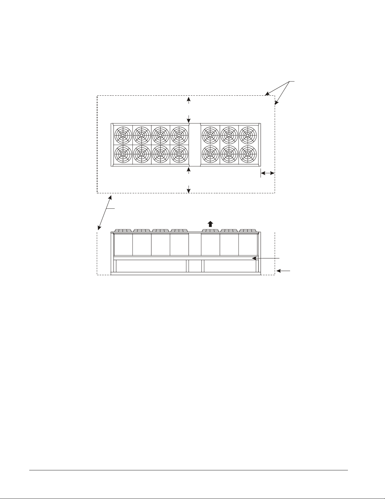
Clearance Requirements
Figure 2, Clearance Requirements, AGS 230B – 475B
5’-0” if open fence or 50% open wall
6’-0” if solid wall (see note 3 for pit)
5’-0” if open fence or 50% open wall
6’-0” if solid wall (see note 3 for pit)
No obstructions.
Recommended area
required for unit
operation, air flow
and maintenance
access.
10’-0” min. for
Evaporator Removal
See Note 8
See notes 2 & 4
concerning wall
height at unit sides.
Air Flow
No obstructions allowed
above unit at any height
See Note 5
Wall or
Fence
Notes:
1. Minimum side clearance between two units is 12 feet (3.7 meters).
2. Unit must not be installed in a pit or enclosure that is deeper or taller than the height of the unit
unless extra clearance is provided per note 4.
3. Minimum clearance on each side is 8 feet (2.4 meters) when installed in a pit no deeper than the
unit height.
4. Minimum side clearance to a side wall or building taller than the unit height is 6 feet (1.8 meters)
provided no solid wall above 6 feet (1.8 meters) is closer than 12 feet (3.7 meters) to the opposite
side of the unit.
5. Do not mount electrical conduits where they can block service access to compressor controls,
refrigerant driers or valves.
6. There must be no obstruction of the fan discharge.
7. Field installed switches must not interfere with service access or airflow.
8. The 10-ft. clearance required for removal of the evaporator is on the end that the evaporator
connections face. See dimension drawings on page 27 for details.
9. If the airflow clearances cannot be met, see the following page.
6 IMM AGS-1
Page 7
Restricted Airflow
General
The clearances required for design operation of AGS air-cooled condensers are described in the
previous section. Occasionally, these clearances cannot be maintained due to site restrictions such as
units being too close together or a fence or wall restricting airflow, or both.
The McQuay AGS chillers have several features that can mitigate the problems attributable to
restricted airflow.
• The “W” shape of the condenser section allows inlet air for these coils to come in from both sides
and the bottom. All the coils in one "W" section serve one compressor. Every compressor
always has its own independent refrigerant circuit.
• The MicroTech II control is proactive in response to off-design conditions. In the case of
single or compounded influences restricting airflow to the unit, the microprocessor will act to
keep the compre ssor(s) running ( at reduced capacity) as l ong as possib le, rat her than all owing a
shut-off on high discharge p ressure.
Figure 3, Coil and Fan Arrangement
The following sections discuss the most common situations of condenser air restriction and give
capacity and power adjustment factors for each. Note that in unusually severe conditions, the
MicroTech II controller would adjust the unit operation to remain online until a less severe condition
is reached.
IMM AGS-1 7
Page 8
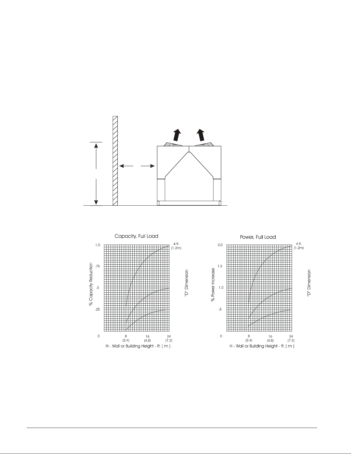
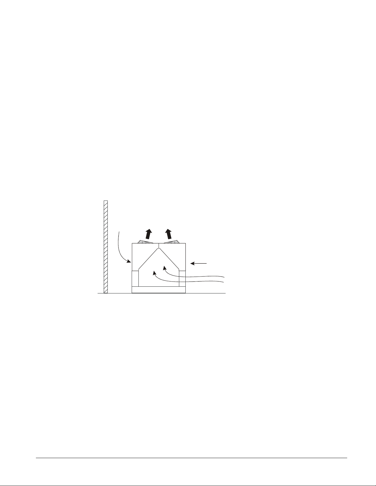
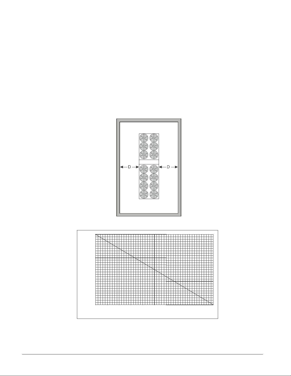
Case 1, Building or Wall on One Side of One Unit
The existence of a screening wall, or the wall of a building, in close proximity to an air-cooled chiller
is common in both rooftop and ground level applications. Hot air recirculation on the coils adjoining
the wall will increase compressor discharge pressure, decreasing capacity and increasing power
consumption.
When close to a wall, it is desirable to place chillers on the north or east side of them. It is also
desirable to have prevailing winds blowing parallel to the unit’s long axis. The worst case is to have
wind blowing hot discharge air into the wall.
Figure 4, Unit Adjacent to Wall
D
H
Figure 5, Adjustment Factors
5 ft.
(1.5m)
6 ft.
(1.8m)
5 ft.
(1.5m)
6 ft.
(1.8m)
8 IMM AGS-1
Page 9
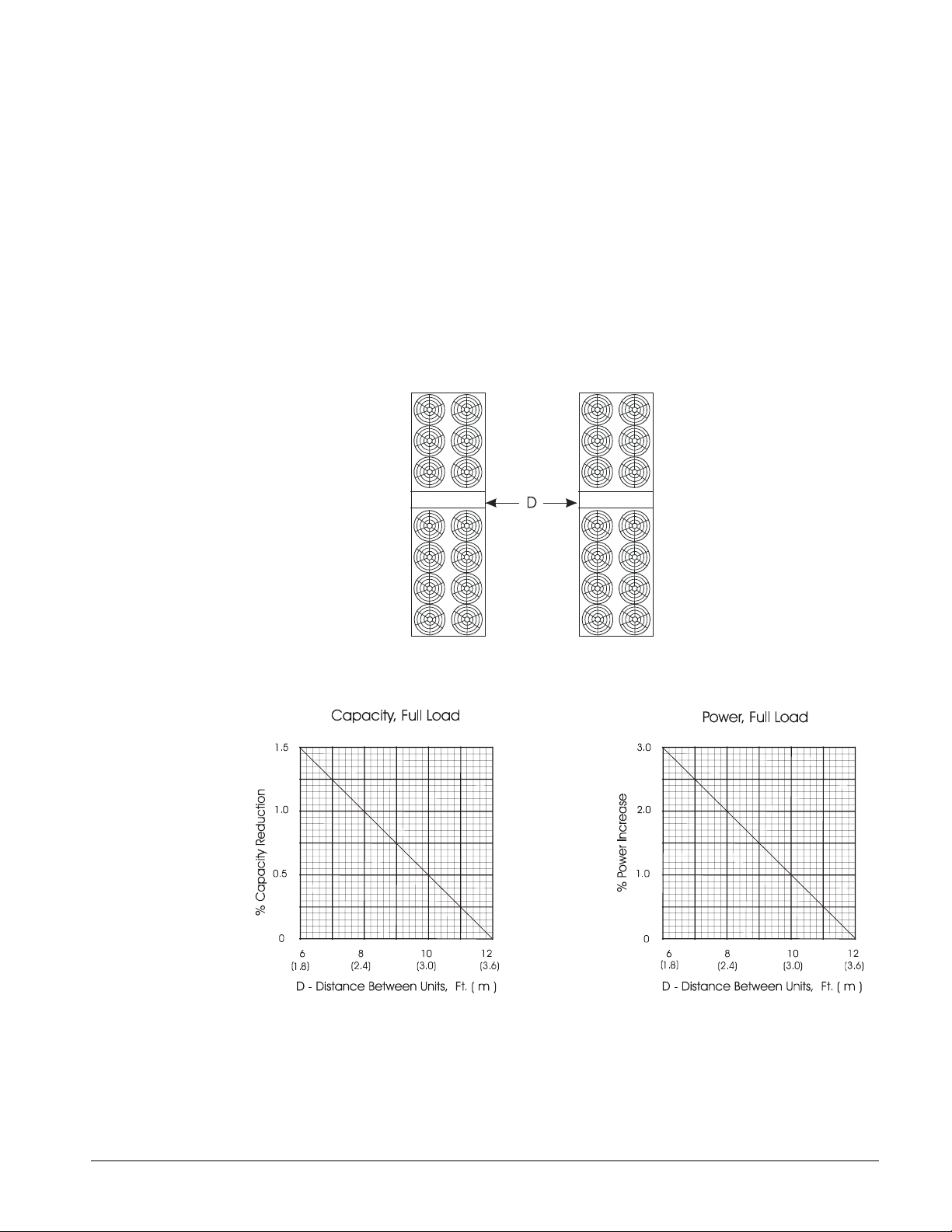
Case 2, Two Units Side By Side
Two or more units sited side by side are common. If spaced closer than 12 feet (3.7 meters) it is
necessary to adjust the performance of each unit; circuits adjoining each other are affected. If one of
the two units also has a wall adjoining it, see Case 1. Add the two adjustment factors together and
apply to the unit located between the wall and the other unit.
Mounting units end to end will not necessitate adjusting performance. Depending on the actual
arrangement, sufficient space must be left between the units for access to the control panel door
opening and/or evaporator tube removal. See “Clearance” section of this guide for requirements for
specific units.
Pit or solid wall surrounds should not be used where the ambient air temperature exceeds 105°F
(40°C).
Figure 6, Two Units Side by Side
Figure 7, Adjustment Factor
IMM AGS-1 9
Page 10
Case 3, Open Screening Walls
Decorative screening walls are often used to help conceal a unit either on grade or on a rooftop.
These walls should be designed such that the combination of their open area and distance from the
unit do not require performance adjustment. It is assumed that the wall height is equal to, or less than
the unit height when mounted on its base support. This is usually satisfactory for concealment. If the
wall height is greater than the unit height, see Case 4, Pit Installation.
The distance from the sides of the unit to the side walls should be sufficient for service and opening
control panel doors.
If each side wall is a different distance from the unit, the distances can be averaged, providing either
wall is not less than 8 feet (2.4 meters) from the unit. For example, do not average 4 feet and 20 feet
to equal 12 feet.
Figure 8, Open Screening Walls
Figure 9, Wall Free Area vs. Distance
6
(1.8)
to Unit - Ft. (M)
D - Distance from Wall
5
(1.5)
01020304050
% Open Wall Area
10 IMM AGS-1
Page 11
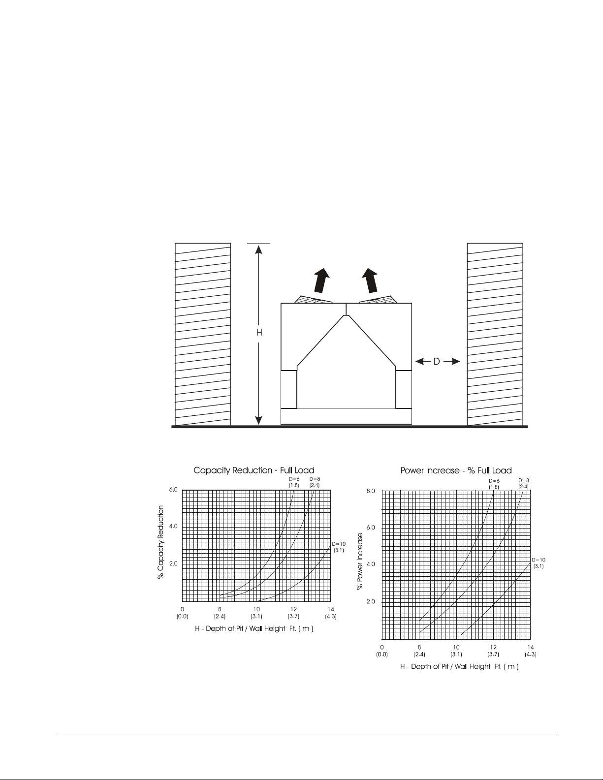
Case 4, Pit/Solid Wall Installation
Pit installations can cause operating problems and great care should be exercised if they are to be used
on an installation. Recirculation and restriction can both occur. A solid wall surrounding a unit is
substantially the same as a pit and the data presented in this case should be used.
Steel grating is sometimes used to cover a pit to prevent accidental falls or trips into the pit. The
grating material and installation design must be strong enough to pr event such accidents, yet p rovide
abundant open area or serious recirculation problems will occur. Have any pit installation reviewed by
McQuay application engineers prior to installation to discuss whether it has sufficient airflow
characteristics. The installation design engineer must approve the work and is responsible for design
criteria.
Figure 10, Pit Installation
Figure 11, Adjustment Factor
IMM AGS-1 11
Page 12
Vibration Isolators
Vibration isolators are recommended for all roof-mounted installations or wherever vibration
transmission is a consideration. The following section "Lifting and Mounting Weights" contains the
location of unit lifting holes and the load at each location. Mounting holes dimensions and the
bearing weight at each hole given.
The unit should be initially installed on shims or blocks at the illustrated "free height" of the isolator
that is six inches for the McQuay isolators shown. When all piping, wiring, flushing, charging, etc. is
complete, the springs should be adjusted upward to load them and to provide clearance to free the
blocks, which are then removed.
Installation of spring isolators requires flexible pipe connections and at least three feet of conduit flex
tie-ins. Piping and conduit should be supported independently from the unit so as not to stress
connections.
Figure 12, Spring Flex Isolators
Table 1, Spring Vibration Isolators, AGS 230 – 320, Part Numbers and Spring Colors
Model
AGS230
AGS250
AGS270
AGS300
AGS320
Notes:
1. The same isolators are used when the chiller is supplied with the optional copper finned condenser coils.
2. The -2- or -4- indicates that two or four springs are used in the isolator.
M1 M2 M3 M4 M5 M6 M7 M8 Kit Num ber
CP-2-28 CP-2-31 CP-2-28 CP-2-31 CP-2-31 CP-2-28 CP-2-31 CP-2-28
Green Gray Green Gray Gray Green Gray Green
CP-2-28 CP-2-31 CP-2-28 CP-2-31 CP-2-32 CP-2-31 CP-4-26 CP-2-28
Green Gray Green Gray White Gray Purple Green
CP-2-28 CP-4-26 CP-2-31 CP-2-32 CP-2-32 CP-2-31 CP-4-26 CP-2-28
Green Purple Gray White White Gray Purple Green
CP-2-28 CP-4-26 CP-2-31 CP-2-32 CP-2-32 CP-2-31 CP-4-26 CP-2-28
Green Purple Gray White White Gray Purple Green
CP-2-28 CP-4-26 CP-2-31 CP-2-32 CP-2-32 CP-2-31 CP-4-26 CP-2-28
Green Purple Gray White White Gray Purple Green
12 IMM AGS-1
Mounting Location (See Footprint Drawings Figure 13 or Figure 14)
350348101
350348102
350348103
Page 13
Table 2, Spring Vibration Isolators, AGS 340 – 475, Part Numbers and Spring Colors
Model
AGS340
AGS370
AGS400
AGS420
AGS440
AGS450
AGS475
Mounting Location (See Footprint Drawings Figure 15 or Figure 16)
M1 M2 M3 M4 M5 M6
CP-2-28 CP-4-26 CP-2-28 CP-4-26 CP-4-26 CP-2-28
Green Purple Green Purple Purple Green
CP-2-28 CP-4-26 CP-2-31 CP-4-26 CP-4-26 CP-2-31
Green Purple Gray Purple Purple Gray
CP-2-28 CP-4-26 CP-2-31 CP-4-26 CP-4-27 CP-2-31
Green Purple Gray Purple Orange Gray
CP-2-31 CP-4-26 CP-2-31 CP-4-27 CP-4-27 CP-2-31
Gray Purple Gray Orange Orange Gray
CP-2-31 CP-4-26 CP-4-26 CP-4-27 CP-4-27 CP-4-26
Gray Purple Purple Orange Orange Purple
CP-2-31 CP-4-26 CP-4-26 CP-4-27 CP-4-27 CP-4-26
Gray Purple Purple Orange Orange Purple
CP-2-31 CP-4-26 CP-4-26 CP-4-27 CP-4-27 CP-4-26
Gray Purple Purple Orange Orange Purple
Continued
Model
AGS340
AGS370
AGS400
AGS420
AGS440
AGS450
AGS475
Notes:
M7 M8 M9 M10 M11 M12 Kit Number
CP-4-26 CP-2-28 CP-2-31 CP-2-27 CP-2-27 CP-2-27
Purple Green Gray Orange Orange Orange
CP-4-26 CP-2-28 CP-2-31 CP-2-28 CP-2-31 CP-2-28
Purple Green Gray Green Gray Green
CP-4-26 CP-2-31 CP-2-31 CP-2-28 CP-2-31 CP-2-28
Purple Gray Gray Green Gray Green
CP-4-26 CP-2-31 CP-2-31 CP-2-28 CP-2-31 CP-2-28
Purple Gray Gray Green Gray Green
CP-4-26 CP-2-31 CP-2-31 CP-2-28 CP-2-31 CP-2-28
Purple Gray Gray Green Gray Green
CP-4-26 CP-2-31 CP-2-31 CP-2-28 CP-2-31 CP-2-28
Purple Gray Gray Green Gray Green
CP-4-26 CP-2-31 CP-2-31 CP-2-28 CP-2-31 CP-2-28
Purple Gray Gray Green Gray Green
1. The same isolators are used when the chiller is supplied with the optional copper finned condenser coils.
2. The -2- or -4- indicates that two or four springs are used in the isolator.
Mounting Location (Table Continued)
350348104
350348105
350348106
350348107
350348108
Table 3, Neoprene-in-Shear Isolators, AGS 230 – 320, Part Numbers
Model
AGS230 4-RED 4-RED 4-RED 4-RED 4-RED 4-RED 4-RED 4-RED 350348201
AGS250 4-RED 4-RED 4-RED 4-RED 4-GREEN 4-RED 4-RED 4-RED 350348202
AGS270 4-RED 4-RED 4-RED 4-GREEN 4-GREEN 4-RED 4-RED 4-RED
AGS300 4-RED 4-RED 4-RED 4-GREEN 4-GREEN 4-RED 4-RED 4-RED
AGS320 4-RED 4-RED 4-RED 4-GREEN 4-GREEN 4-RED 4-RED 4-RED
Note:
M1 M2 M3 M4 M5 M6 M7 M8 Kit Number
1. The same isolators are used when the chiller is supplied with the optional copper finned condenser coils.
Mounting Location (See Footprint Drawings Figure 13 or Figure 14)
350348203
Table 4, Neoprene-in-Shear Isolators, AGS 340 – 475, Part Numbers
Model
AGS340 4-RED 4-RED 4-RED 4-RED 4-RED 4-RED
AGS370 4-RED 4-GREEN 4-RED 4-GREEN 4-GREEN 4-RED
AGS400 4-RED 4-GREEN 4-RED 4-GREEN 4-GREEN 4-RED
AGS420 4-RED 4-GREEN 4-RED 4-GREEN 4-GREEN 4-RED
AGS440 4-RED 4-GREEN 4-RED 4-GREEN 4-GREEN 4-RED
AGS450 4-RED 4-GREEN 4-RED 4-GREEN 4-GREEN 4-RED
AGS475 4-RED 4-GREEN 4-RED 4-GREEN 4-GREEN 4-RED
Mounting Location (See Footprint Drawings Figure 15 or Figure 16)
M1 M2 M3 M4 M5 M6
Table continued on following page for M7 thr ough M12 plus kit numbers .
IMM AGS-1 13
Page 14

Model
M7 M8 M9 M10 M11 M12 Kit Number
Mounting Location (Table Continued)
AGS340 4-RED 4-RED 4-RED 4-RED 4-RED 4-RED 350348204
AGS370 4-GREEN 4-RED 4-RED 4-RED 4-RED 4-RED
AGS400 4-GREEN 4-RED 4-RED 4-RED 4-RED 4-RED
AGS420 4-GREEN 4-RED 4-RED 4-RED 4-RED 4-RED
AGS440 4-GREEN 4-RED 4-RED 4-RED 4-RED 4-RED
AGS450 4-GREEN 4-RED 4-RED 4-RED 4-RED 4-RED
AGS475 4-GREEN 4-RED 4-RED 4-RED 4-RED 4-RED
Note:
1. The same isolators are used when the chiller is supplied with the optional copper finned condenser coils.
Lifting and Mounting Weights
Figure 13, AGS 230B – AGS 250B Lifting and Mounting Locations
350348205
88.0
(2235.2)
NOTE: Evaporator connections point left.
Figure 14, AGS 270B - AGS 320B Lifting and Mounting Locations
2 (51)
Typical Spacing
for Isolator
Mounting (8)
2 (51)
Typical Spacing
for Isolator
Mounting (8)
88.0
(2235.2)
14 IMM AGS-1
Page 15
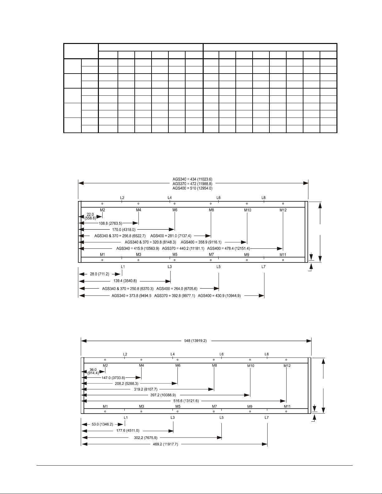
Table 5, AGS 230B - AGS 320B Lifting and Mounting Weights
AGS
Model
Lbs. 2183 3043 2563 2563 3043 2183 1683 2325 1681 2322 2322 1681 2325 1683
230B
250B
270B
300B
320B
(kg) 991 1382 1164 1164 1382 991 764 1055 763 1054 1054 763 1055 764
Lbs. 2183 3043 2700 2704 3374 2509 1683 2325 1681 2322 2693 2018 2421 1814
(kg) 991 1382 1226 1228 1532 1139 764 1055 763 1054 1223 916 1099 824
Lbs. 2509 3374 2841 2841 3374 2509 1814 2421 2018 2693 2693 2018 2421 1814
(kg) 1139 1532 1290 1290 1532 1139 824 1099 916 1223 1223 916 1099 824
Lbs. 2520 3383 2871 2871 3383 2520 1821 2425 2043 2721 2721 2043 2425 1821
(kg) 1144 1536 1304 1304 1536 1144 827 1101 928 1235 1235 928 1101 827
Lbs. 2550 3407 2956 2956 3407 2550 1838 2435 2111 2797 2797 2111 2435 1838
(kg) 1158 1547 1342 1342 1547 1158 834 1106 958 1270 1270 958 1106 834
NOTES:
1. Lifting tabs with 2 ½ in. (63.5 mm) holes at location "L" on side of base rail.
2. 1 in. (25.4 mm) mounting holes at location "M" on bottom of base rails.
Lifting Weight for Each Point lb (kg) Mounting Loads for Each Point lb. (kg)
L1 L2 L3 L4 L5 L6 M1 M2 M3 M4 M5 M6 M7 M8
Figure 15, AGS 340B – AGS 400B Lifting and Mounting Locations
NOTE: Evaporator connections point left.
Figure 16, AGS 420B - AGS 475B Lifting and Mounting Locations
2 (51)
Typical Spacing
for Isolator
Mounting (8)
88.0
(2235.2)
88.0
(2235.2)
2 (51)
Typical Spacing
for Isolator
Mounting (8)
IMM AGS-1 15
Page 16
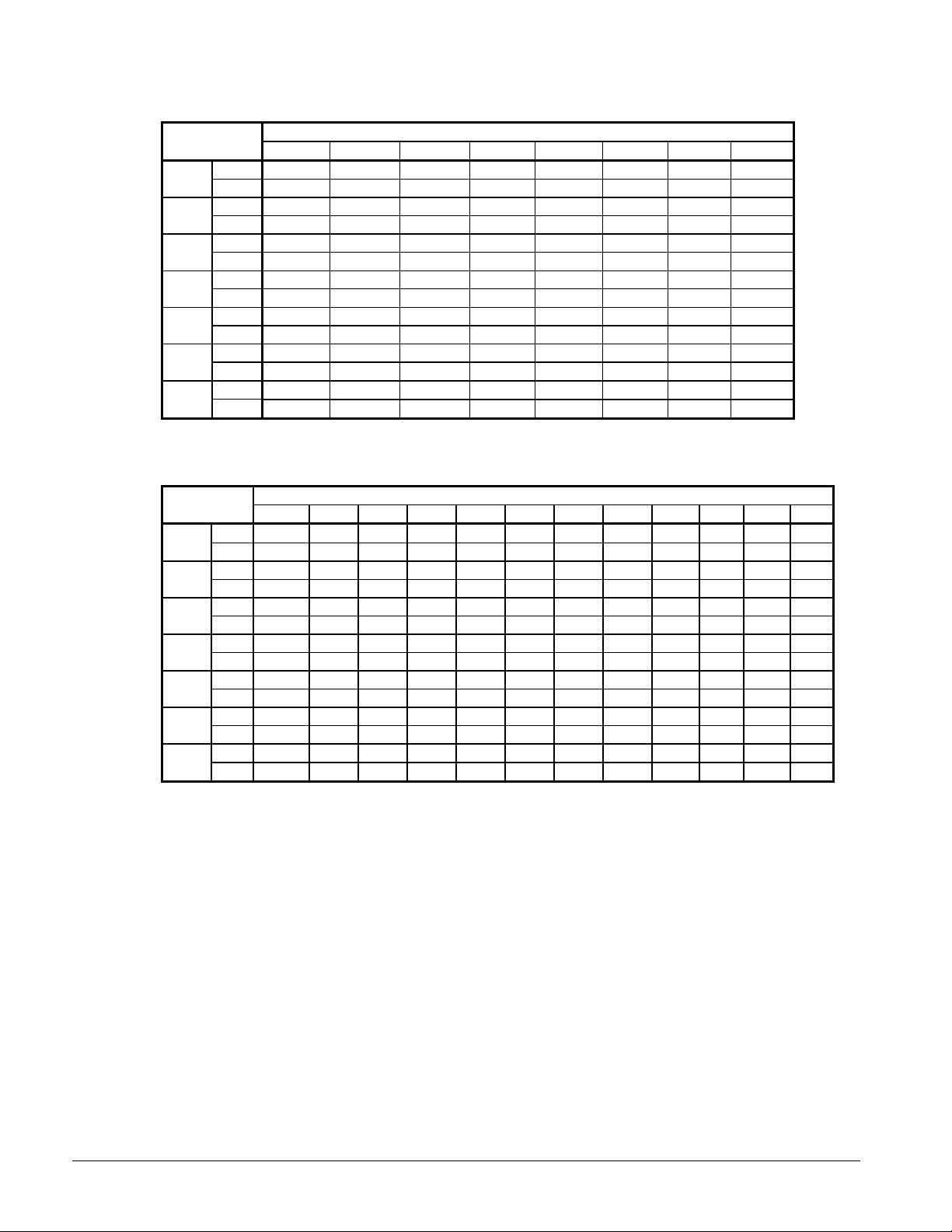
Table 6, AGS 340B - AGS 475B Lifting Weights
Lifting Weight for Each Point lb (kg)
340B
370B
400B
420B
440B
450B
475B
AGS
Model
lbs 2312 3173 2681 2681 3352 2473 3192 2880
(kg) 1050 1441 1217 1217 1522 1123 1449 1307
lbs 2449 3296 2951 2951 3617 2742 3519 3216
(kg) 1112 1496 1340 1340 1642 1245 1597 1460
lbs 2449 3296 3119 3117 3917 3044 3519 3216
(kg) 1112 1496 1416 1415 1778 1382 1597 1460
lbs 2751 3596 3285 3285 3917 3044 3519 3216
(kg) 1249 1633 1491 1491 1778 1382 1597 1460
lbs 2783 3624 3361 3361 3945 3076 3519 3216
(kg) 1263 1645 1526 1526 1791 1396 1597 1460
lbs 2783 3624 3361 3361 3945 3076 3519 3216
(kg) 1263 1645 1526 1526 1791 1396 1597 1460
lbs 2783 3624 3361 3361 3945 3076 3519 3216
(kg) 1263 1645 1526 1526 1791 1396 1597 1460
L1 L2 L3 L4 L5 L6 L7 L8
Table 7, AGS 340B - AGS 475B Mounting Weights
Mounting Loads for Each Point lb. (kg)
340B
370B
400B
420B
440B
450B
475B
AGS
Model
lbs 1798 2442 1787 2426 2426 1787 2442 1798 1726 1557 1645 1484
lbs 1885 2511 1981 2638 2638 1981 2511 1885 1973 1803 1867 1706
lbs 1885 2511 1981 2638 3055 2357 2562 1977 1973 1803 1867 1706
lbs 1977 2562 2357 3055 3055 2357 2562 1977 1973 1803 1867 1706
lbs 1999 2579 2425 3128 3128 2425 2579 1999 1973 1803 1867 1706
lbs 1999 2579 2425 3128 3128 2425 2579 1999 1973 1803 1867 1706
lbs 1999 2579 2425 3128 3128 2425 2579 1999 1973 1803 1867 1706
M1 M2 M3 M4 M5 M6 M7 M8 M9 M10 M11 M12
kg 816 1109 811 1101 1101 811 1109 816 784 707 747 674
kg 856 1140 899 1198 1198 899 1140 856 896 819 847 775
kg 856 1140 899 1198 1387 1070 1163 897 896 819 847 775
kg 897 1163 1070 1387 1387 1070 1163 897 896 819 847 775
kg 908 1171 1101 1420 1420 1101 1171 908 896 819 847 775
kg 908 1171 1101 1420 1420 1101 1171 908 896 819 847 775
kg 908 1171 1101 1420 1420 1101 1171 908 896 819 847 775
16 IMM AGS-1
Page 17
Chilled Water Pump
It is required that the chilled water pumps' starter be wired to and controlled by the chiller's
microprocessor. The controller will energize the pump whenever at least one circuit on the chiller is
enabled to run, whether there is a call for cooling or not. The pump will also be energized when the
controller senses a near-freezing temperature at the chiller outlet sensor to assist in cold weather
freeze protection. Connection points are shown in Figure 24 on page 37.
Water Piping
Due to the variety of piping practices, it is advisable to follow the recommendations of local
authorities. They can supply the installer with the proper building and safety codes required for a
safe and proper installation.
NOTE: Chilled water piping must enter and exit the unit platform between the base rail and the
bottom of the condenser coil in the approximately 30-inch width shown on Figure 20 and Figure 21.
The piping should be designed with a minimum number of bends and changes in elevation to keep
system cost down and performance up. It should contain:
1. Vibration eliminators to reduce vibration and noise transmission to the building.
2. Shutoff valves to isolate the unit from the piping system during unit servicing.
3. Manual or automatic air vent valves at the high points of the system and drains at the low parts in
the system. The evaporator should not be the highest point in the piping system.
4. Some means of maintaining adequate system water pressure (i.e., expansion tank or regulating
valve).
5. Water temperature and pressure indicators located at the unit to aid in unit servicing.
6. A strainer to remove foreign matter from the water before it enters the pump. The strainer should
be placed far enough upstream to prevent cavitation at the p ump inlet (co nsult p ump
manufacturer for recommendations). The use of a strainer will prolong pump life and help
maintain high system performance levels.
NOTE: A strainer must also be placed in the supply water line just prior to the inlet of the
evaporator. This will aid in preventing foreign material from entering the evaporator and causing
damage or decreasing its performance. Care must also be exercised if welding pipe or flanges to
the evaporator connections to prevent any weld slag from entering the vessel.
7. Any water piping to the unit must be protected to prevent freeze-up if below freezing
temperatures are expected. See page 18 for further information on freeze protection.
CAUTION
If a separate disconnect is used for the 115V supply to the unit, it should power t he entire
control circuit, not just the evaporator heaters. It should be clearly marked so that it is not
accidentally shut off during cold seasons. Freeze damage to the evaporator could result. If
the evaporator is drained for winter freeze protection, the heaters must be de-energized to
prevent burnout.
8. If the unit is used as a replacement chiller on a previously existing piping system, the system
should be thoroughly flushed prior to unit installation and then regular chilled water ana l ysis and
chemical water treatment is recommended immediately at equipment start-up.
9. The total water quantity in the system should be sufficient to prevent frequent "on-off" cycling.
For air conditioning systems, system gallons equal to 4 times the flow rate is recommended.
IMM AGS-1 17
Page 18

10. In the event glycol is added to the water system as a late addition for freeze protection, recognize
that the refrigerant suction pressure will be lower, cooling performance less, and water side
pressure drop greater. If the percentage of glycol is large, or if propylene is employed in lieu of
ethylene glycol, the added pressure drop and loss of performance could be substantial.
11. For ice making or glycol operation, a different freezestat pressure value can be desired. The
freezestat setting can be manually changed through the MicroTech II controller.
A preliminary leak check should be made prior to insulating the water piping and filling the system.
Piping insulation should include a vapor barrier to prevent moisture condensation and possible
damage to the building structure. It is important to have the vapor barrier on the outside of the
insulation to prevent condensation within the insulation on the cold surface of the pipe.
System Water Volume
It is important to have adequate water volume in the system to provide an opportunity for the chiller
to sense a load change, adjust to the change and stabilize. As the expected load change becomes
more rapid, a greater water volume is needed. The system water volume is the total amount of water
in the evaporator, air handling products and associated piping. If the water volume is too low,
operational problems can occur including rapid compressor cycling, rapid loading and unloading of
compressors, erratic refrigerant flow in the chiller, improper motor cooling, shortened equipment life
and other undesirable consequences.
For normal comfort cooling applications where the cooling load changes relatively slowly, we
recommend a minimum system volume of four minutes times the flow rate (gpm). For example, if the
design chiller flow rate is 800 gpm, we recommend a minimum system volume of 3200 gallons (800
gpm x 4 minutes).
For process applications where the cooling load can change rapidly, additional system water volume
is needed. A process example would be a quenching tank. The load would be very stable until the
hot material is immersed in the water tank. Then, the load would increase drastically. For this type of
application, system volume can need to be increased.
Since there are many other factors that can influence performance, systems can successfully operate
below these suggestions. However, as the water volume decreases below these suggestions, the
possibility of problems increases.
Variable Speed Pumping
Variable water flow involves changing the water flow through the evaporator as the load changes.
McQuay chillers are designed for this duty, pro vided that the rate of change in water flow is slow and
the minimum and maximum flow rates for the vessel are not exceeded.
The recommended maximum change in water flow is 10 percent of the change per minute.
The water flow through the vessel must remain be tween the minimum and maximum values listed on
page 23. If flow drops below the minimum allowable, large reductions in heat transfer can occur. If
the flow exceeds the maximum rate, excessive pressure drop and tube erosion can occur.
Evaporator Freeze Protection
Flooded evaporators are popular with chiller manufacturers because of their inherent high efficiency.
Care must be exercised in the equipment design and in the operation of these evaporators to prevent
freezing between 32°F and -20°F.
For protection down to 0°F (-18°C), the AGS chillers are equipped with thermostatically controlled
evaporator heaters that help protect against freeze-up provided the chiller goes through its normal
pumpdown cycle. Several occurrences can prevent this normal pumpdown from happening:
1. A power failure will prevent pumpdown and there is a potential for freezing outdoor equipment in
systems using 100 percent water as the chilled fluid.
18 IMM AGS-1
Page 19

2. Unit shutdown due to a fault will cause immediate compressor shutdown without the pumpdown
cycle. This situation can be remedied by correcting the fault, restarting the unit, and allowing it
to go through its normal shutdown pumpdown.
NOTE: The heaters come from the factory connected to the control power circuit. The control power
can be rewired to a separate 115V supply (do not wire directly to the heater). If this is done, the
disconnect switch should be clearly marked to avoid accidental deactivation of the heater during
freezing temperatures. Exposed chilled water piping also requires protection.
It is required that the chilled water pump’s starter be wired to, and controlled by, the chiller's
microprocessor. The controller will energize the pump whenever at least one circuit on the chiller is
enabled to run, whether there is a call for cooling or not. The pump will also be energized when the
controller senses a near-freezing temperature at the chiller outlet sensor to assist in cold weather
freeze protection. Connection points are shown in Figure 24 on page 37.
For additional protection to -20°F (-29°C) and to protect against the consequences described above, it
is recommended that at least one of the following procedures be used during periods of sub-freezing
temperatures:
1. Addition of a concentration of a glycol anti-freeze with a freeze point 15 degrees below the
lowest expected temperature. This will result in decreased capacity and increased pressure drop.
Note: Do not use automotive grade antifreezes as they contain inhibitors harmful to chilled water
systems. Only use glycols specifically designated for use in building cooling systems.
2. Draining the water from outdoor equipment and piping and blowing the chiller tubes dry from the
chiller. Do not energize the chiller heater when water is drained from the vessel.
CAUTION
If fluid is absent from the evaporator, the evaporator heater must be de-energized to avoid
burning out the heater and causing damage from the high temperatures.
3. Providing opera tion o f the chilled water pump, circ ulating water thro ugh the chille d water system
and through the evaporator. The chiller micropr oce ssor will automatically start up the pump if so
wired.
Table 8, Freeze Protection
Temperature
°F (°C)
20 (6.7)16181112
10 (-12.2) 25 29 17 20
0 (-17.8) 33 36 22 24
-10 (-23.3) 39 42 26 28
-20 (-28.9) 44 46 30 30
-30 (-34.4) 48 50 30 33
-40 (-40.0) 52 54 30 35
-50 (-45.6) 56 57 30 35
-60 (-51.1) 60 60 30 35
Notes:
1. These figures are examples only and cannot be appropriate to every situation. Generally, for an extended margin of
protection, select a temperature at leas t 10
should be adjusted for solutions less t han 30% glycol.
2. Glycol of less than 20% concentration is not recommended bec aus e of t he pot ent ial for bacterial growth and loss of
heat transfer efficiency.
Ethylene Glycol Propylene Glycol Ethylene Glycol Propylene Glycol
For Freeze Protection For Burst Protection
Percent Volume Glyc ol Concentration Required
°F lower than the expected lowest ambient temperature. Inhibitor levels
IMM AGS-1 19
Page 20
Operating Limits:
Maximum standby ambient temperature, 130°F (55°C)
Maximum operating ambient temperature, 115°F (46°C), or 125°F (52°C) with optional high ambient
package
Minimum operating ambient temperature (standard), 35°F (2°C)
Minimum operating ambient temperature (optional low-ambient control), 0°F (-18°C)
Leaving chilled water range, 38°F to 50°F (3°C to 10°C)
Leaving chilled fluid range (with anti-freeze), 20°F to 50°F (7°C to 10°C)
Operating Delta-T range, 6 degrees F to 16 degrees F (10.8 C to 28.8 C)
Maximum operating inlet fluid temperature, 66°F (19°C)
Maximum startup inlet fluid temperature, 90°F (32°C)
Maximum non-operat i ng inlet fluid temperature, 100°F (38°C)
NOTE: Contact the local McQuay sales office for operation outside of these limits.
Flow Switch
A water flow switch must be mounted in the leaving chilled water line to prove that there is adequate
water flow to the evaporator before the unit can start. It also serves to shut down the unit in the event
that water flow is interrupted in order to guard against evaporator freeze-up.
A flow switch is available from McQuay under ordering number 017503300. It is a paddle-type
switch and adaptable to any pipe size from 1" (25mm) to 8" (203mm) nominal.
Certain minimum flow rates are required to close the switch and are listed in Table 9. Installation
should be as shown in Figure 17.
Electrical connections in the unit control center should be made at terminals 60 and 67. The normally
open contacts of the flow switch should be wired between these two terminals. Flow switch contact
quality must be suitable for 24 VAC, low current (16ma). Flow switch wire must be in separate
conduit from any high voltage conduc tors (115 VAC and higher) and have an insul ation r ating of 6 00
volts.
Figure 17, Flow Switch
1 1/4" (32mm) pipe
dia. min. after switch
Flow direction marked
on switch
1" (25mm) NPT flow
switch connection
Tee
1 1/4" (32mm) pipe
dia. min. before switch
Table 9, Switch Minimum Flow Rates
NOMINAL PIPE
SIZE
INCHES (MM)
5 (127) 58.7 (3.7)
6 (152) 79.2 (5.0)
8 (203) 140 (8.8)
Note: Water pressure differential switches are not recommended for
outdoor applications.
MINIMUM REQUIRED FLOW
TO ACTIVATE SWITCH
GPM (LPS)
20 IMM AGS-1
Page 21

Figure 18, Typical Field Water Piping
LEGEND
FS
Flow Switch
IN OUT
TW
TW
FS
Notes:
1. Connections for vent and drain fittings are located on t he t op and bottom of both evaporator water heads.
2. Piping must be supported to avoid putting strain on t he evaporator nozzles.
TW
Gate Valve
Pressure Gauge & Cock
Thermal Well
Flexible Co nnector
Strainer
Manual Vent
Water Connections
Water pipi ng to the evaporator must be bro ught out through the side o f the unit between the ver tical
supports. The dimensional drawings on page 27 and 28 give the necessary dimensions and locations
for all piping connections. Evaporator piping connections face toward the left side of the unit when
looking at control panel #3.
Refrigerant Charge
All units are designed for use with R-134a and are shipped with a full operating charge. The
operating charge for each unit is shown in the Physical Data Tables beginning on page 24.
Glycol Solutions
When using glycol anti-freeze solutions the chiller's capacity, glycol solution flow rate, and pressure
drop through the evaporator can be calcul ated using the following formulas and tables.
Note: The procedure below does not specify the type of glycol. Use the derate factors found in Table
10 for corrections when using propylene glycol and those in Table 11 for ethylene glycol.
1. Capacity - Cooling capacity is reduced from that with plain water. To find the reduced value,
multiply the chiller’s water system tonnage by the capacity correction factor to find the chiller’s
capacity when using glycol.
2. Flow - To determine flow (or delta-T) knowing delta-T (or flow) and capacity:
()( )( )
GPM−=
Pressure drop - To determine pressure dr op through the evap orator when using glycol, enter
3.
24
the water pressure drop curve at the water flow rate. Multiply the water pressure drop found
there by the "PD" factor to obtain corrected glycol pressure drop.
Power - To determine glycol system kW, multiply the water system kW by the factor designated
4.
"Power".
Test coolant with a clean, accurate glycol solution hydrometer (similar to that found in service
stations) to determine the freezing point. Obtain percent glycol from the freezing point table below.
On glycol applications the supplier normally recommends that a minimum of 20% solution by weight
be used for protection against corrosion.
factorflowtons
TDelta
IMM AGS-1 21
Page 22

CAUTION
Do not use automotive grade antifreeze. Industrial grade glycols must be used. Automotive antifreeze
contains inhibitors that will cause plating on the co pper tubes w ithin the chiller evapo rator. The
type and handling of glycol used must be consistent with local codes.
Table 10, Propylene Glycol Factors
Freeze
%
E.G
Point
oFo
10 26 -3.3 0.994 0.998 1.036 1.104
20 18 -7.8 0.979 0.990 1.060 1.256
30 7 -13.9 0.964 0.983 1.092 1.424
40 -7 -21.7 0.943 0.973 1.132 1.664
50 -28 -33.3 0.920 0.963 1.182 1.944
Cap. Power Flow PD
C
Water Flow and Pressure Drop
The chilled water flow through the evapor ator should be ad justed to meet specified co nditions. T he
flow rates must fall between the minimum and maximum values shown in table on the following page.
Flow rates below the minimum values shown will result in laminar flow that will reduce efficiency,
cause erratic operation of the electronic expansion valve and could cause low temperature cutouts.
On the other hand flow rates exceeding the maximum values shown can cause erosion on the
evaporator water connections and tubes.
Table 11, Ethylene Glycol Factors
Freeze
%
P.G
Point
oFo
10 26 -3.3 0.985 0.993 1.017 1.120
20 19 -7.2 0.964 0.983 1.032 1.272
30 9 -12.8 0.932 0.969 1.056 1.496
40 -5 -20.6 0.889 0.948 1.092 1.792
50 -27 -32.8 0.846 0.929 1.139 2.128
Cap. Power Flow PD
C
Measure the chilled water pressure drop through the evap orator at field installe d pressure taps. It is
important not to include valve or strainer pressure drop in these readings.
22 IMM AGS-1
Page 23

Figure 19, Evaporator Pressure Drops
AGS 230-270
AGS 300
AGS 340
AGS 440-475
AGS 370-420
AGS 320
Minimum/Nominal/Maximum Flow Rates
AGS
Unit
Size
230B 330 5.3 529 12.8 882 32.0
250B 365 6.5 585 15.3 975 37.5
270B 401 7.8 642 18.2 1070 44.0
300B 424 6.1 679 14.2 1132 35.2
320B 451 4.9 722 11.5 1203 39.0
340B 501 7.0 801 16.0 1336 42.0
370B 540 6.1 864 14.4 1440 36.0
400B 576 6.8 922 16.0 1537 40.0
420B 613 7.5 981 18.2 1635 44.0
440B 640 6.4 1025 15.2 1708 38.0
450B 660 6.7 1057 16.4 1762 41.0
475B 680 7.1 1089 17.0 1815 43.0
Minimum Flow Nominal Flow Maxim um Flow
Flow ∆
gpm ft. gpm ft. gpm ft
∆PFlow∆∆∆∆PFlow∆∆∆∆P
∆∆
IMM AGS-1 23
Page 24

Physical Data
Table 12, Physical Data, AGS 230B – AGS 270B
AGS MODEL NUMBER
230B 250B 270BDATA
Ckt 1 Ckt 2 Ckt 1 Ckt 2 Ckt 1 Ckt 2
BASIC DATA
Cap. @ ARI Conditions, tons (kW) 220.5 (774) 243.9 (856) 267.5 (939)
Unit Operating Charge lbs (kg) 298 (135) 298 (135) 298 (135) 321 (145) 321 (145) 321 (145)
Cabinet Dimensions
L x W x H, in. (mm)
Unit Operating Weight, lbs. (kg) 16285 (7394) 17301 (7855) 18319 (8317)
Unit Shipping Wei ght, lbs (kg) 15862 (7201) 16877 (7662) 17895 (8124)
COMPRESSORS, SCREW, SEMI-HERMETIC
Nominal Capacity, tons (kW) 100 (350) 100 (350) 100 (350) 125 (437) 125 (437) 125 (437)
CONDENSERS, HIGH EFFICIENCY FIN AND TUBE TYPE WITH INTEGRAL SUBCOOLER
Coil Face Area, ft2. (m2) 159 (14.8) 159 (14.8) 159 (14.8) 213 (19.8) 213 (19.8) 213 (19.8)
Fins Per Inch x Rows Deep 16 x 3 16 x 3 16 x 3 16 x 3 16 x 3 16 x 3
CONDENSER FANS, DIRECT DRIVE PROPE L L ER TYPE
No. of Fans -- Fan Dia., in. (mm) 12 – 30 (762) 14 – 30 (762) 16 – 30 (762)
No. of Motors -- hp (kW) 12 – 2 (1.5) 14 – 2 (1.5) 16 – 2 (1.5)
Fan & Motor RPM, 60Hz 1140 1140 1140
60 Hz Fan Tip Speed, fpm 8954 8954 8954
60 Hz Total Unit Airflow, ft3/min 129,600 151,200 172,800
EVAPORATOR, FLOODED SHELL AND TUBE
Shell Dia.-Tube Length
in.(mm) - in. (mm)
Evaporator R-134a Charge lbs (kg) 182 (37) 182 (37) 182 (37) 182 (37) 182 (37) 182 (37)
Water Volume, gallons (liters) 48 (182) 48 (182) 48 (182)
Max. Water Pressure, psi (kPa) 150 (1034) 150 (1034) 150 (1034)
Max. Refrigerant Press., psi (kPa) 200 (1379) 200 (1379) 200 (1379)
278 x 88 x 100
(7087 x 2235 x 2550)
24 (610) – 96 (2438) 24 (610) – 96 (2438) 24 (610) – 96 (2438)
317 x 88 x 100
(8052 x 2235 x 2550)
355.x 88 x 100
(9017 x 2235 x 2550)
Table 13, Physical Data, AGS 300B – AGS 320B
AGS MODEL NUMBER
300B 320BDATA
Ckt 1 Ckt 2 Ckt 1 Ckt 2
BASIC DATA
Unit Cap. @ ARI, tons (k W) 283.1 (994) 300.9 (1056)
Unit Operating Charge lbs (kg) 335 (152) 335 (152) 360 (163) 360 (163)
Cabinet Dimensions
L x W x H, in. (mm)
Unit Operating Weight, lbs. (kg) 18447 (8375) 18787 (8266)
Unit Shipping Wei ght, lbs (kg) 17995 (8170) 18272 (8295)
COMPRESSORS, SCREW, SEMI-HERMETIC
Nominal Capacity, tons (kW) 125 (437) 150 (525) 150 (525) 150 (525)
CONDENSERS, HIGH EFFICIENCY FIN AND TUBE TYPE WITH INTEGRAL SUBCOOLER
Coil Face Area, ft2. (m2) 213 (19.8) 213 (19.8) 213 (19.8) 213 (19.8)
Fins Per Inch x Rows Deep 16 x 3 16 x 3 16 x 3 16 x 3
CONDENSER FANS, DIRECT DRIVE PROPE L L ER TYPE
No. of Fans -- Fan Dia., in. (mm) 16 – 30 (762) 16 – 30 (762)
No. of Motors -- hp (kW) 16 – 2 (1.5) 16 – 2 (1.5)
Fan & Motor RPM, 60Hz 1140 1140
60 Hz Fan Tip Speed, fpm 8954 8954
60 Hz Total Unit Airflow, ft3/min 172,800 172,800
EVAPORATOR, FLOODED SHELL AND TUBE
Shell Dia.-Tube Length
in.(mm) - in. (mm)
Evaporator R-134a Charge lbs (kg) 196 (89) 196 (89) 221 (100) 221 (100)
Water Volume, gallons (liters) 51 (195) 59 (221)
Max. Water Pressure, psi (kPa) 150 (1034) 150 (1034)
Max. Refrigerant Press., psi (kPa) 200 (1379) 200 (1379)
355 x 88 x 100
(9017 x 2235 x 2550)
24 (610) – 96 (2438) 26 (660) – 96 (2438)
355 x 88 x 100
(9017 x 2235 x 2550)
24 IMM AGS-1
Page 25

Table 14, Physical Data, AGS 340B – AGS 400B
AGS MODEL NUMBER
DATA 340B 370B 400B
Ckt. 1 Ckt. 2 Ckt. 3 Ckt. 1 Ckt. 2 Ckt. 3 Ckt. 1 Ckt. 2 Ckt. 3
BASIC DATA
Unit Cap. @ ARI, tons (k W) 334.1 (1173) 360.0 (1264) 384.3 (1349)
Unit Operating Charge, lbs (kg) 285 (129) 285 (129) 285 (129) 312 (141) 312 (141) 312 (141) 312 (141) 335 (152) 335 (152)
Cabinet Dim., L x W x H, in. (mm)
Unit Operating Weight, lbs. (kg) 23507 (10672) 25645 (11643) 26667 (11734)
Unit Shipping Wei ght, lbs (kg) 22958 (10101) 25034 (11015) 26056 (11829)
COMPRESSORS, SCREW, SEMI-HERMETIC
Nominal Capacity, tons (kW) 100 (350) 100 (350) 100 (350) 100 (350) 100 (350) 125 (437) 100 (350) 125 (437) 125 (437)
CONDENSERS, HIGH EFFICIENCY FIN AND TUBE TYPE WITH INTEGRAL SUBCOOLER
Coil Face Area, ft2. (m2) 159 (14.8) 159 (14.8) 159 (14.8) 159 (14.8) 159 (14.8) 213 (19.9) 159 (14.8) 213 (19.9) 213 (19.9)
Fins Per Inch x Rows Deep 16 x 3 16 x 3 16 x 3 16 x 3 16 x 3 16 x 3 16 x 3 16 x 3 16 x 3
CONDENSER FANS, DIRECT DRIVE PROPEL L ER TYPE
No. of Fans -- Fan Diameter, in.
(mm)
No. of Motors -- hp (kW) 18 – 2 (1.5) 20 – 2 (1.5) 22 – 2 (1.5)
Fan & Motor RPM, 60Hz 1140 1140 1140
60 Hz Fan Tip Speed, fpm 8954 8954 8954
60 Hz Total Unit Airflow, ft3/min 194,400 216,000 237,600
EVAPORATOR, FLOODED SHELL AND TUBE
Shell Dia., Tube Length in.(mm) 26 (660) – 108 (2743) 30 (762) – 108 (2743) 30 (762) – 108 (2743)
Evaporator R-134a Charge lbs
(kg
Water Volume, gallons (liters) 63 (237) 70 (263) 70 (263)
Max. Water Pressure, psi (kPa) 150 (1034) 150 (1034) 150 (1034)
Max. Refrigerant Press., psi (k Pa) 200 (1379) 200 (1379) 200 (1379)
164 (74) 164 974) 164 (74) 191 (86) 191 (86) 191 (86) 191 (86) 191 (86) 191 (86)
434 x 88 x 100
(11024 x 2235 x 2550)
18 – 30 (762) 20 – 30 (762) 22 – 30 (732)
472 x 88 x 100
(11989 x 2235 x 2550)
510 x 88 x 100
(12954 x 2235 x 2550)
Table 15, Physical Data, AGS 420B – AGS 440B
AGS MODEL NUMBER
DATA 420B 440B
Ckt. 1 Ckt. 2 Ckt. 3 Ckt. 1 Ckt. 2 Ckt. 3
BASIC DATA
Unit Cap. @ ARI, tons (k W) 408.8 (1435) 427.1 (1499)
Unit Operating Charge, lbs (kg) 335 (152) 335 (152) 335 (152) 358 (162) 358 (162) 358 (162)
Cabinet Dim., L x W x H, in. (mm)
Unit Operating Weight, lbs. (kg) 27684 (12568) 28042 (12731)
Unit Shipping Wei ght, lbs (kg) 27072 (12291) 27345 (12415)
COMPRESSORS, SCREW, SEMI-HERMETIC
Nominal Capacity, tons (kW) 125 (437) 125 (437) 125 (437) 125 (437) 125 (437) 150 (525)
CONDENSERS, HIGH EFFICIENCY FIN AND TUBE TYPE WITH INTEGRAL SUBCOOLER
Coil Face Area, ft2. (m2) 213 (19.9) 213 (19.9) 213 (19.9) 213 (19.9) 213 (19.9) 213 (19. 9)
Fins Per Inch x Rows Deep 16 x 3 16 x 3 16 x 3 16 x 3 16 x 3 16 x 3
CONDENSER FANS, DIRECT DRIVE PROPE L L ER TYPE
No. of Fans -- Fan Dia., in. (mm) 24 – 30 (762) 24 – 30 (762)
No. of Motors -- hp (kW) 24 – 2 (1.5) 24 – 2 (1.5)
Fan & Motor RPM, 60Hz 1140 1140
60 Hz Fan Tip Speed, fpm 8954 8954
60 Hz Total Unit Airflow, ft3/min 259,200 259,200
EVAPORATOR, FLOODED SHELL AND TUBE
Shell Dia. -- Tube Length
in.(mm) - in. (mm)
Evaporator R-134a Charge lbs
(kg
Water Volume, gallons (liters) 70 (263) 79 (300)
Max. Water Pressure, psi (kPa) 150 (1034) 150 (1034)
Max. Refrigerant Press., psi (kPa) 200 (1379) 200 (1379)
548 x 88 x 100
(13919 x 2235 x 2550)
30 (762) – 108 (2743) 30 (762) – 108 (2743)
191 (86) 191 (86) 191 (86) 214 (97) 214 (97) 214 (97)
548 x 88 x 100
(13919 x 2235 x 2550)
IMM AGS-1 25
Page 26

Table 16, Physical Data, AGS 450B – AGS 475B
AGS MODEL NUMBER
DATA 450B 475B
Ckt. 1 Ckt. 2 Ckt. 3 Ckt. 1 Ckt. 2 Ckt. 3
BASIC DATA
Unit Cap. @ ARI, tons (k W) 440.5 (1546) 453.9 (1593)
Unit Operating Charge, lbs (kg) 358 (162) 358 (162) 358 (162) 358 (162) 358 (162) 358 (162)
Cabinet Dim., L x W x H, in. (mm)
Unit Operating Weight, lbs. (kg) 28042 (12731) 28042 (12731)
Unit Shipping Wei ght, lbs (kg) 27345 (12415) 27345 (12415)
COMPRESSORS, SCREW, SEMI -HERMETIC
Nominal Capacity, tons (kW) 125 (437) 150 (525) 150 (525) 150 (525) 150 (525) 150 (525)
CONDENSERS, HIGH EFFICIENCY FIN AND TUBE TYPE WITH INTEGRAL SUBCOOLER
Coil Face Area, ft2. (m2) 213 (19.9) 213 (19.9) 213 (19.9) 213 (19.9) 213 (19.9) 213 (19. 9)
Fins Per Inch x Rows Deep 16 x 3 16 x 3 16 x 3 16 x 3 16 x 3 16 x 3
CONDENSER FANS, DIRECT DRIVE PROPELLER TYPE
No. of Fans -- Fan Dia., in. (mm) 24 – 30 (762) 24 – 30 (762)
No. of Motors -- hp (kW) 24 – 2 (1.5) 24 – 2 (1.5)
Fan & Motor RPM, 60Hz 1140 1140
60 Hz Fan Tip Speed, fpm 8954 8954
60 Hz Total Unit Airflow, ft3/sec 259,200 259,200
EVAPORATOR, FLOODED SHELL AND TUBE
Shell Dia. -- Tube Length
in.(mm) - in. (mm)
Evaporator R-134a Charge lbs
(kg
Water Volume, gallons (liters) 79 (300) 79 (300)
Max. Water Pressure, psi (kPa) 150 (1034) 150 (1034)
Max. Refrigerant Press. psi (kP a) 200 (1379) 200 (1379)
548 x 88 x 100
(13919 x 2235 x 2550)
30 (762) – 108 (2743) 30 (762) – 108 (2743)
214 (97) 214 (97) 214 (97) 214 (97) 214 (97) 214 (97)
548 x 88 x 100
(13919 x 2235 x 2550)
26 IMM AGS-1
Page 27

Dimensional Data
A
)
5.5
Figure 20, Dimensions, AGS 230B – AGS 320B
Note: See page 14 for lifting loc ations, m ounting locat ions, weights and m ounting loads.
51.1
(1297.9)
36.9
(937.3)
SINGLE POINT POWER ENTRY "D"
INLET
FE
C
FIELD CONTROL
CONNECTION
CONTROL
CIRCUIT #1
CONTROL
CIRCUIT #2
OUTLET
OPENING FOR
CHILLER WATER PIPING
POWER ENTRY POINT
0.875 (22.2)
KNOCK-OUT
PANEL
PANEL
POWER ENTRY POINT
0.875 (22.2) KNOCK-OUT
(139.7)
SINGLE POINT POWER
BOX OPTION
AGS 230-300
26.7 (678.2)
AGS 320
25.7 (652.8)
B
POWER ENTRY
12.0 (304.8) POWER ENTRY
LOCATION FAR SIDE
88.0
(2235.2)
DWG. 330556901
NOTE: Chilled water piping must enter and exit the unit platform between the base rail and the bottom of the
condenser coil in the “F” dimension on the side shown above.
AGS Unit
Size
AGS 230
AGS 250
AGS 270-320
Dimensions
Inches (mm)
ABCDEF
278.8
(7081.5)
316.9
(8049.3)
355.2
(9022.1))
133.4
(3388.4)
133.4
(3388.4)
171.6
(4358.6)
78.4
(1991.4)
78.4
(1991.4)
116.6
(2961.6)
192.6
(4892.0)
192.6
(4892.6)
230.8
(5862.3
Water Piping
Inches (mm)
44.8
(1137.4)
44.8
(1137.4)
80.9
(2054.8)
30.0
(762.8)
30.0
(762.8)
31.4
(797.6)
Evaporator
Connection
Size
Inches (mm)
8
(203.2)
8
(203.2)
8
(203.2)
Fan Modules
Total
Module1Module
Fans
12 Fan 6 6
14 Fan 6 8
16 Fan 8 8
100.4
(2550.4
2
IMM AGS-1 27
Page 28

Figure 21, Dimensions, AGS 340B –475B
A
)
SING
Note: See page 14 for lifting loc ations, m ounting locat ions, weights and m ounting loads.
SINGLE POINT POWER ENTRY "D"
INLET
FIELD CONTROL
CONNECTION
H
J
POWER ENTRY POINT
0.875 (22.2) KNOCK-OUT
CONTROL
PANE L
CIRCUIT #1
CONTROL
PANE L
CIRCUIT #2
5.5
(139.7)
LE POINT POWER
BOX OPTION
CONTROL PANEL
CIRCUIT #3
F
K
G
C
B
OUTLET
OPENING FOR
CHILLER WATER PIPING
POWER ENTRY
POWER ENTRY POINT
0.875 (22.2) KNOCK-OUT
12.0 (304.8) POWER ENTRY
LOCATION FAR SIDE
E
POWER ENTRY POINT
0.875 (22.2) KNOCK-OUT
NOTE: Chilled water piping must enter and exit the unit platform between the base rail and the bottom of the
condenser coil in the “G” dimension on the side shown above.
AGS
Unit
Size
AGS
340
AGS
370
AGS
400
AGS
420-475
Dimensions
Inches (mm)
ABCDE F GHJK
434.2
(11027.9)
472.4
(11998.2)
510.6
(12968.5)
548. 8
(13939.0)
133.4
(3388.0)
133.4
(3388.1)
133.4
(3388.1)
171.6
(4358.4)
90.3
(2292.4)
90.3
(2292.4)
87.3
(2140.0)
125.5
(3186.4)
192.6
(4892.0)
192.6
(4892.0)
192.6
(4892.0)
230. 8
(5862.3)
288.8
(7335.5)
288.8
(7335.5)
327.0
(8305.8)
365.2
(9276.1)
Water Piping
Inches (mm)
44.7
(1137.4)
44.7
(1137.4)
44.7
(1137.4)
80.9
(2054.8)
30.0
(762.8)
30.0
(762.8)
30.0
(762.8)
31.4
(797.6)
Evaporator Connections
Inches (mm)
51.1
52.1
52.1
52.1
36.9
(937.3)
36.9
(937.3)
35.9
911.9)
35.9
911.9)
(652.8)8(203.2)
(911.9)10(254.0)
(911.9)10(254.0)
(911.9)10(254.0)
(1297.9)
(1323.3)
(1323.3)
(1323.3)
25.7
27.7
27.7
27.7
Evaporator
Connection
Size
Inches (mm)
Total
Fans
18 Fan 6 6 6
20 Fan 6 6 8
22 Fan 6 8 8
24 Fans 8 8 8
88.00
(2235.2)
DWG. 330557001
Fan Modules
Module1Module2Module
3
100.41
(2550.4
28 IMM AGS-1
Page 29

Wind Baffles and Hail Guards
G
A
Wind Baffles/Hail Guards are a field installed option that are used to stabilize unit operation in high wind
areas and to assist in operation at low ambient temperatures. Figure 22 shows a typical panel assembly on
an AGS unit. The actual number of panels and parts will vary by model size. The parts are shown in the
table below and referenced by balloon numbers. The baffles extend out 20 inches from each side.
Figure 22, Installation Sequence
Rib Attachment (First)
RIB FLANGES ON THE END
MUST POINT TO CENTER
OF COIL TO HAVE A FINISHED
LOOK. INTERIOR RIB FLANGES
CAN POINT IN ANY DIRECTION.
U
I
I
R
E
N
T
T
C
V
O
I
L
C
L
A
Front Panel Attachment (Second)
PLACE FRONT "A" AND
FASTEN TO BOTH SIDES
C
O
L
I
C
I
A
L
V
E
R
U
2
T
N
T
I
C
B
A
ATTACH ALL RIBS TO
COIL VERTICAL CHANNELS.
E
D
PLACE FRONT "B" BY LAPPIN
OVER "A" AND REPEAT
ATTACHMENT PROCEDURE.
1
3
Top Panel Attachment (Last)
E
ATTACH TOP "A" AT HORIZONTAL COIL CHANNEL FIRST.
IMM AGS-1 29
THIS WILL SQ UA RE THE PANEL .
OVERLAP THE FRONT PANEL FLANGE.
C
A
R
E
I
T
T
V
I
U
N
A
D
L
I
C
O
L
B
C
ATTACH LEFT SIDE SECOND.
LAP PANEL "B" OVER PANEL "A"
ND REPEAT ATTACHMENT PROCEDURE.
Page 30

Table 17, Packing List
L
O
t
Description Part Number Bubble Number
Vertical Support Rib 074758501 1
Top Cover 330409401 2
¼ - 20 x ½” Screw (Place in Poly Bag) 046093807
Front Panel 330409501 3
Figure 23, Components
Top Panel, Install Last
Overlap the Front panel
T
REAR (AGAINST UNIT)
VERTICAL SUPPORT RIB TOP COVER FRONT PANE
P
Front Panel, Install Second
Rib, Install Firs
30 IMM AGS-1
Page 31

Electrical Data
Field Wiring
General
Wiring must comply with all applicable codes and ordinances. Damage to the equipment caused by
wiring not complying with specifications is not covered under warrant y.
An open fuse indicates a short, ground, or overload. Before replacing a fuse or restarting a compressor or
fan motor, the trouble must be found and corrected.
Copper wire is required for all power lead terminations at the unit and copper must be used for all other
wiring to the unit.
AGS units can be ordered with main power wiring for either multiple-point power (standard) or singlepoint connection (optional).
If the standard multiple-point power wiring is ordered, power connections are made to the individual
circuit power panels located between the condenser sections. Two connections are required for models
AGS 230 through 320 and three are required for models AGS 340 through 475. See the dimension
drawings on pages 27 and 28 for detailed locations. Separate disconnects are required for each electrical
circuit if McQuay factory-mounted disconnects are not ordered.
If the optional single-point power connection is ordered, a single large power connection point is
provided and located in a box on the base of the unit. See the dimension drawings on pages 27 and 28 for
the location. Factory wiring from the box to the individual compressor power panels on the unit is sized
in accordance with the National Electrical Code. A disconnect is required and can be furnished as a
factory option. The 115-volt control transformer is factory mounted and wired.
It can be desirable to have the unit evaporator heaters on a separate disconnect switch from the main unit
power supply so that the unit power can be shut down without defeating the freeze protection provided by
the cooler heaters. See page 18 for details.
Power blocks are standard on all size units. Multi-point power connections can have circuit breakers as an
option. The single-point circuit breaker option has a main circuit breaker and individual breakers in each
panel.
CAUTION
AGS unit compressors are single-direction rotation compressors and can be damaged if rotated in
the wrong direction. For this reason proper phasing of electrical power is important. Electrical
phasing must be A, B, C for electrical phases 1, 2 and 3 (A =L1, B=L2, C=L3) for sing le or multiple
point wiring arrangements. The solid-state starters contain phase reversal protection.
ALTER THE WIRING TO THE STARTERS.
DO NOT
IMM AGS-1 31
Page 32

Table 18, AGS 230B – AGS 475B, Electrical Data, Optional Single-Point
AGS
UNIT
VOLTS HZ
SIZE
230
250
270
300
320
340
370
400
420
440
450
475
Notes
1. Table based on 75°C field wire.
2. A “HACR” breaker is a circuit breaker designed for use on equipment with multiple motors. It stands for Heating, Air Conditioning, and Refrigeration.
3. Complete electrical notes are on page 36.
460 475 6 250 2 2.5 600 600
575
460 519 6 300 2 3.0 600 700
575
460 555 6 300 2 3.0 700 700
575
460 586 6 350 2 3.0 700 800
575
460 611 6 350 2 3.0 700 800
575
460 688 12 4/0 2 3.0 800 800
575
460 732 12 250 2 4.0 800 800
575
460 768 12 250 2 4.0 800 800
575
460 804 12 250 2 4.0 1000 1000
575
460 835 12 300 2 4.0 1000 1000
575
460 860 12 300 2 4.0 1000 1000
575
460 885 12 300 2 4.0 1000 1000
575
60
60
60
60
60
60
60
60
60
60
60
60
MINIMUM
CIRCUIT
FIELD WIRE
AMPACITY
(MCA)
QTY
418 6 4/0 2 2.0 500 500
447 6 4/0 2 2.0 500 600
471 6 250 2 2.5 600 600
496 6 250 2 2.5 600 700
516 6 300 2 3.0 600 700
605 12 3/0 2 3.0 700 700
634 12 3/0 2 3.0 700 800
658 12 4/0 2 3.0 800 800
683 12 4/0 2 3.0 800 800
708 12 4/0 2 3.0 800 800
728 12 4/0 2 3.0 800 800
748 12 250 2 4.0 800 800
POWER SUPPLY
(Conduit Connection)
WIRE
GAUGE
QTY
HUB
NOMINAL
SIZE (In.)
FIELD FUSE SIZE or
HACR BREAKER SIZE
RECOM-
MENDED
MAXIMUM
Table 19, AGS 230B – AGS 320B, Electrical Data, Standard Multiple-Point, Two-Circuit Units
ELECTRICAL CIRCUIT 1 (COMP 1) ELECTRICAL CIRCUIT 2 (COMP 2)
AGS
UNIT
SIZE
VOLTS HZ
MIN.
CIRCUIT
AMPS
(MCA)
230
250
270
300
320
460
575
460
575
460
575
460
575
460
575
Notes:
1. Table based on 75°C field wire.
2. Complete electrical notes are on page 36.
3. 3/0 wire is required for the disconnect switch option, 2/0 can be used for power block connection.
262 6 3/0 (3) 1 3.0 350 450 262 6 3/0 (3) 1 3.0 350 450
60
230 3 250 1 2.5 300 400 230 3 250 1 2.5 300 400
262 6 3/0 (3) 1 3.0 350 450 306 6 3/0 1 3.0 400 500
60
230 3 250 1 2.5 300 400 260 6 3/0 (3) 1 3.0 350 400
306 6 3/0 1 3.0 400 500 306 6 3/0 1 3.0 400 500
60
260 6 3/0 (3) 1 3.0 350 400 260 6 3/0 (3) 1 3.0 350 400
306 6 3/0 1 3.0 400 500 337 6 4/0 1 3.0 450 500
60
260 6 3/0 (3) 1 3.0 350 400 285 6 3/0 1 3.0 350 450
337 6 4/0 1 3.0 450 500 337 6 4/0 1 3.0 450 500
60
285 6 3/0 1 3.0 350 450 285 6 3/0 1 3.0 350 450
POWER SUPPLY FIELD FUSING POWER SUPPLY FIELD FUSING
MIN.
CIRCUIT
AMPS
(MCA)
FIELD WIRE
WIRE
QTY
GAUGE
HUB
(Conduit
Connection)
QTY
FIELD WIRE
WIRE
QTY
GAUGE
HUB
(Conduit
Connection)
HUB
QTY
SIZE
REC
FUSE
SIZE
MAX
FUSE
SIZE
HUB
SIZE
REC
FUSE
SIZE
MAX
FUSE
SIZE
32 IMM AGS-1
Page 33

Table 20, AGS 340B–AGS 475B, Electrical Data, Standard Multiple-Point, (Circuits # 1 & 2)
ELECTRI CAL CIRCUIT 1 (COMP 1) ELECTRI CAL CIRCUIT 2 (COMP 2)
AGS
UNIT
SIZE
VOLTS HZ
MIN.
CIRCUIT
AMPS
(MCA)
340
370
400
420
440
450
475
Notes:
1. Table based on 75°C field wire
2. Complete electrical notes are on page 36.
3. 3/0 wire is required for the disconnect switch option, 2/0 can be used for power block connection.
460
575
460
575
460
575
460
575
460
575
460
575
460
575
262 6 3/0 (3) 1 3.0 350 450 262 6 3/0 (3) 1 3.0 350 450
60
230 3 250 1 2.5 300 400 230 3 250 1 2.5 300 400
262 6 3/0 (3) 1 3.0 350 450 262 6 3/0 (3) 1 3.0 350 450
60
230 3 250 1 2.5 300 400 230 3 250 1 2.5 300 400
262 6 3/0 (3) 1 3.0 350 450 306 6 3/0 1 3.0 400 500
60
230 3 250 1 2.5 300 400 260 6 3/0 (3) 1 3.0 350 400
306 6 3/0 1 3.0 400 500 306 6 3/0 1 3.0 400 500
60
260 6 3/0 (3) 1 3.0 350 400 260 6 3/0 (3) 1 3.0 350 400
306 6 3/0 1 3.0 400 500 306 6 3/0 1 3.0 400 500
60
260 6 3/0 (3) 1 3.0 350 400 260 6 3/0 (3) 1 3.0 350 400
306 6 3/0 1 3.0 400 500 337 6 4/0 1 3.0 450 500
60
260 6 3/0 (3) 1 3.0 350 400 285 6 3/0 1 3.0 350 450
337 6 4/0 1 3.0 450 500 337 6 4/0 1 3.0 450 500
60
285 6 3/0 1 3.0 350 450 285 6 3/0 1 3.0 350 450
POWER SUPPLY FIELD FUSING POWER SUPPLY FIELD FUSING
MIN.
CIRCUIT
AMPS
(MCA)
FIELD WIRE
WIRE
QTY
GAUGE
HUB
(Conduit
Connection)
QTY
FIELD WIRE
WIRE
QTY
GAUGE
HUB
(Conduit
Connection)
HUB
QTY
SIZE
REC
FUSE
SIZE
MAX
FUSE
SIZE
HUB
SIZE
REC.
FUSE
SIZE
MAX.
FUSE
SIZE
Table 20, Electrical Data, AGS 340B – 475B, (Circuit #3)
ELECTRICAL CIRCUIT 3 (COMP 3)
AGS
UNIT
SIZE
VOLTS HZ
MINIMUM
CIRCUIT
AMPS
(MCA)
340
370
400
420
440
450
475
Notes:
1. Table based on 75°C field wire.
2. Complete electrical notes are on page 36.
3. 3/0 wire is required for the disconnect switch option, 2/0 can be used for power block connection.
460 262 6 3/0 (3) 1 3.0 350 450
575
460 306 6 3/0 1 3.0 400 500
575
460 306 6 3/0 1 3.0 400 500
575
460 306 6 3/0 1 3.0 400 500
575
460 337 6 4/0 1 3.0 450 500
575
460 337 6 4/0 1 3.0 450 500
575
460 337 6 4/0 1 3.0 450 500
575
60
230 3 250 1 2.5 300 400
60
260 6 3/0 (3) 1 3.0 350 400
60
260 6 3/0 (3) 1 3.0 350 400
60
260 6 3/0 (3) 1 3.0 350 400
60
285 6 3/0 1 3.0 350 450
60
285 6 3/0 1 3.0 350 450
60
285 6 3/0 1 3.0 350 450
POWER SUPPLY FIELD FUSING
HUB
FIELD WIRE
WIRE
QTY
GAUGE
(Conduit
Connection)
HUB
QTY
SIZE
REC.
FUSE
SIZE
MAX.
FUSE
SIZE
IMM AGS-1 33
Page 34

Table 21, AGS230B–AGS 475B, Compressor and Condenser Fan Motor Amp Draw
AGS
UNIT
SIZE
230
250
270
300
320
340
370
400
420
440
450
475
RATED LOAD AMPS
VOLTS HZ
460 195 195 - 3.0 20 585 585 575
460 195 225 - 3.0 20 585 675 575
460 225 225 - 3.0 20 675 675 575
460 225 250 - 3.0 20 675 750 575
460 250 250 - 3.0 20 750 750 575
460 195 195 195 3.0 20 585 585 585
575
460 195 195 225 3.0 20 585 585 675
575
460 195 225 225 3.0 20 586 675 675
575
460 225 225 225 3.0 20 675 675 675
575
460 225 225 250 3.0 20 675 675 750
575
460 225 250 250 3.0 20 675 750 750
575
460 250 250 250 3.0 20 750 750 750
575
CIRCUIT#1CIRCUIT#2CIRCUIT
60
171 171 -
60
171 190
60
190 190 -
60
190 210 -
60
210 210 -
60
171 171 171
60
171 171 190
60
171 190 190
60
190 190 190
60
190 190 210
60
190 210 210
60
210 210 210
#3
NO OF
FAN
MOTORS
12
14
16
16
16
18
20
22
24
24
24
24
FAN
MOTORS
FLA
(EACH)
2.7 18 513 513 -
2.7 18 513 570 -
2.7 18 570 570 -
2.7 18 570 630 -
2.7 18 630 630 -
2.7 18 513 513 513
2.7 18 513 513 570
2.7 18 513 570 570
2.7 18 570 570 570
2.7 18 570 570 630
2.7 18 570 630 630
2.7 18 630 630 630
L R A
FAN
MOTORS
(EACH)
SOLID-STATE STARTING INRUSH
AMPS PER COMPRESSOR
CIRCUIT #1 CIRCUIT #2 CIRCUIT #3
Table 22, AGS 230B – AGS 475B, Customer Wiring Information With Single-Point Power
WIRING TO STANDARD UNIT POWER
AGS
VOLTS HZ
UNIT
SIZE
460
230
575
460
250
575
460
270
575
460
300
575
460
320
575
460
340
575
460
370
575
460
400
575
460
420
575
460
440
575
460
450
575
460
475
575
1. Terminal size amps are the maximum amps that the power block is rated for.
2. Complete electrical notes are on page 36.
60
60
60
60
60
60
60
60
60
60
60
60
MAXIMUM
TERMINAL
AMPS
1000 #6-350 800 #6-350
1000 #6-350 800 #6-350
1000 #6-350 800 #6-350
1000 #6-350 800 #6-350
1000 #6-350 800 #6-350
1000 #6-350 800 #6-350
1000 #6-350 800 #6-350
1000 #6-350 800 #6-350
1000 #6-350 800 #6-350
1000 #6-350 800 #6-350
1000 #6-350 1000 #6-350
1000 #6-350 800 #6-350
1000 #6-350 1000 #6-350
1000 #6-350 800 #6-350
1000 #6-350 1000 #6-350
1000 #6-350 800 #6-350
1000 #6-350 1000 #6-350
1000 #6-350 800 #6-350
1000 #6-350 1000 #6-350
1000 #6-350 800 #6-350
1000 #6-350 1000 #6-350
1000 #6-350 800 #6-350
1000 #6-350 1000 #6-350
1000 #6-350 800 #6-350
BLOCK
CONNECTOR LUG RANGE
PER PHASE
(COPPER WIRE ONLY)
WIRING TO OPTIONAL NONFUSED DISCONNECT
DISCONNECT
SIZE
SWITCH IN UNIT
CONNECTOR LUG RANGE
PER PHASE
(COPPER WIRE ONLY)
34 IMM AGS-1
Page 35

Table 23, AGS 230B–AGS 475B, Wiring Information with Multiple-Point
AGS
UNIT
VOLTS HZ
SIZE
230
250
270
300
320
340
370
400
420
440
450
475
Notes:
1. Terminal size amps are the maximum amps that the power block is rated for.
2. Complete electrical notes are on page 36.
460
575
460
575
460
575
460
575
460
575
460
575
460
575
460
575
460
575
460
575
460
575
460
575
TERMINAL SIZE (AMPS) CONNECTOR WIRE RANGE PER PHASE (COPPER WIRE ONLY)
CKT 1 CKT 2 CKT 3 CKT 1 CKT 2 CKT 3
60 400 400 --
60 400 400 --
60 400 400 --
60 400 400 --
60 400 400 --
60 400 400 400
60 400 400 400
60 400 400 400
60 400 400 400
60 400 400 400
60 400 400 400
60 400 400 400
WIRING TO UNIT POWER BLOCK
#6-350 #6-350 --
#6-350 #6-350 --
#6-350 #6-350 --
#6-350 #6-350 --
#6-350 #6-350 --
#6-350 #6-350 #6-350
#6-350 #6-350 #6-350
#6-350 #6-350 #6-350
#6-350 #6-350 #6-350
#6-350 #6-350 #6-350
#6-350 #6-350 #6-350
#6-350 #6-350 #6-350
Table 24, AGS 230B–AGS 475B, Wiring Information with Multiple-Point
AGS
UNIT
SIZE
230
250
270
300
320
340
370
400
420
440
450
475
VOLTS HZ
460
575
460
575
460
575
460
575
460
575
460
575
460
575
460
575
460
575
460
575
460
575
460
575
60 400 400 - 3/0 - 500 3/0 - 500 -
60 400 400 - 3/0 - 500 3/0 - 500 -
60 400 400 - 3/0 - 500 3/0 - 500 -
60 400 400 - 3/0 - 500 3/0 - 500 -
60 400 400 - 3/0 - 500 3/0 - 500 -
60 400 400 400 3/0 - 500 3/0 - 500 3/0 - 500
60 400 400 400 3/0 - 500 3/0 - 500 3/0 - 500
60 400 400 400 3/0 - 500 3/0 - 500 3/0 - 500
60 400 400 400 3/0 - 500 3/0 - 500 3/0 - 500
60 400 400 400 3/0 - 500 3/0 - 500 3/0 - 500
60 400 400 400 3/0 - 500 3/0 - 500 3/0 - 500
60 400 400 400 3/0 - 500 3/0 - 500 3/0 - 500
TERMINAL SIZE (AMPS) CONNECTOR WIRE RANGE PER PHASE (COPPER WIRE ONL Y)
CKT 1 CKT 2 CKT 3 CKT 1 CKT 2 CKT 3
WIRING TO UNIT DISCONNECT S WITCH
IMM AGS-1 35
Page 36

Electrical Data Notes
1. Allowable voltage limits
Unit nameplate 460V/60Hz/3Ph: 414V to 506V
Unit nameplate 575V/60Hz/3Ph: 518V to 632V
Unit wire size ampacity (MCA) is equal to 125% of the largest compressor-motor RLA plus 100% of RLA of
2.
all other loads in the circuit.
Single point power supply requires a single disconnect to supply electrical power to the unit. This power must
3.
be fused.
All field wiring to unit power block or optional nonfused disconnect switch must be copper.
4.
5.
External disconnect switch(s) or HACR breakers must be field supplied.
Note: A non-fused disconnect switch in the cabinet is available as an option for single-point or multi-point
power connections.
6.
All wiring must installed as NEC Class 1 wiring system with conductor rated 600 volts and be done in
accordance with applicable local and national codes.
Recommended time delay fuse size or HACR circuit breakers is equal to 150% of the largest compressor
7.
motor RLA plus 100% of remaining compressor RLAs and the sum of condenser fan FLAs.
Maximum time delay fuse size or HACR circuit breakers is equal to 225% of the largest compressor-motor
8.
RLA plus 100% of remaining compressor RLAs and the sum of condenser fan FLAs.
If 1) the evaporator heater is to be powered during winter shutdown and 2) it is desired to disconnect 460/575
9.
volt power to the unit, then the unit-mounted 3 KVA control transformer can be unwired and a field 115-volt,
30-amp power source wired to terminals TB1-1 and TB1-2. The MicroTech II control must be powered in
order for the heaters to work.
36 IMM AGS-1
Page 37

Field Wiring Diagram
A
A
N
Figure 24, Typical Field Wiring Diagram, Circuit #1 Control Box
Note: Field-wired control connections are made in the control panel for circuit 1 only.
DISCONNECT
(BY OTHERS)
UNIT MAIN
TERMINAL BLOCK
3 PHASE
POWER
SUPPLY
FUSED CONTROL
CIRCUIT TRANSFORMER
NOTE: ALL FIELD WIRING TO BE
INSTALLED AS NEC CLASS 1
WIRING SYSTEM WITH CONDUCTOR
RATED 600 VOLTS
CHW PUMP RELAY #1
120 VAC 1.0 AMP MAX
ALARM BELL
OPTION
FACTORY SUPPLIED ALARM
FIELD WIRE D
ALARM BELL RELAY
CHW PUMP RELAY #2
120 VAC 1.0 AMP MAX
(BY OTHERS)
(BY OTHERS)
120 VAC
GND LUG
TB1
(115 VAC)
1
82
2
85
2
81
75
TB1-2
N
N
24 VAC
TO COMPRESSOR(S)
AND FAN MOTORS
120 VAC
120 VAC
REMOTE STOP
SWITCH
(BY OTHERS)
ICE MODE
SWITCH
(BY OTHERS)
CHW FLOW SWITCH
---MANDATORY–(BY OTHERS)
TIME
CLOCK
NOR. OPEN PUMP AUX.
CONTACTS (OPTIONAL)
4-20MA FOR
CHW RESET
(BY OTHERS)
4-20MA FOR
DEMAND LIMIT
(BY OTHERS)
UTO
ON
UTO
ON
MANUAL
MANUAL
OFF
OFF
TB1
(24 VAC OR 30 VDC)
60
66
897
IF REMOTE STOP CONTROL
IS USED, REMOVE LEAD 897
FROM TERM. 40 TO 53.
60
68
CONTROLLER
60
67
+
-
71
72
PE
+
-
GND
69
70
PE
GND
J11
Rx-/Tx-
Rx-/Tx-
GND
BLACK
WHITE
GREEN
DWG. 330803901 REV. 0B
*COMMUNICATIO
PORT
IMM AGS-1 37
Page 38

Solid State Starters
Solid state starters are standard on all AGS units. A solid state starter uses a silicon-controlled
rectifier (SCR) power section to allow a motor to be brought to full speed with a reduced initial
voltage that increases to full line voltage over a given time. The McQuay motor starter, custom
designed for this specific application, is microprocessor controlled. Along with this starting
technique, the motor starter also provides protection for the motor and monitors its load conditions.
The starter offers:
Solid state design.
•
•
Closed-loop motor current control.
•
Programmable motor protection.
•
Programmable operating parameters.
•
Programmable metering options.
The three-phase starter contains a six-SCR power section with two SCRs per phase connected in
inverse paral lel. This power se ctio n is ca pab le o f pr ovid ing maximum torq ue pe r amp t hrougho ut the
motor’s speed-torque curve with minimal motor and starter heating. At the same time, the starter
continually monitors the amount of current being delivered to the motor, thus helping protecting the
motor from overheating or drawing excessive current. The starter will automatically stop the motor if
the line-to-line current is not within acceptable ranges, or if the current is lost in a line. The motor
current scaling is set according to the motor size and the specific application. The starter circuitry is
contained on a single printed circuit board, which contains all the logic and SCR gate drive circuitry.
Operating messages are displayed on a three-character LED display located in each compressor's
control panel. The LED display on the control card displays:
Operating messages that indicate the status of the motor and/or starter.
•
•
Operating parameters that are programmed into the starter.
•
Fault codes that indicate a problem with the motor application or starter.
Operating Messages
Possible operating messages are as follows:
Message Meaning
noL
Line voltage is not present.
rdy Line voltage is present and starter is ready.
acc Motor is accelerating after a start command has been received.
uts The motor has achieved full speed.
run Motor is operating at full speed, and ramp time has expired.
dCL A Stop command was received and the motor is decelerating with the set
deceleration profile.
OL OL will alternately blink with the normal display on the LED display when
motor thermal overload content has reached 90% to 99% of its capacity.
38 IMM AGS-1
Page 39

OLL The motor thermal overload content has reached 100%, and the motor has
stopped. The motor cannot be restarted until the overloaded motor has
cooled and
OLt is displayed.
OLt The motor thermal overload content has been reduced to 60% or less, and
the motor can be restarted.
ena Passcode protection is enabled.
dis Passcode is disabled.
oxx xx = overload thermal content in percentage. Press the Down button to
toggle to this display.
cxx xx = pending fault.
no Attempted to change a passcode protected parameter without proper
security.
… Three decimal places blink when remote display is active.
Fxx xx Fault Code
Fault Codes
Fault codes will be displayed on the red, three-character LED display. Fault codes indicate a pro blem
with the starter or motor application.
CODE CRITICAL
DESCRIPTION
F1 YES Line phase sequence not ABC
F3 YES System power is not three phase
F5 Line fr equency less than 25hz.
F6 Line frequency greater than 72hz.
F23 Line current unbalance greater than set level.
F24 Line currents are very unbalanced.
F29 YES Operating parameter s have been lost
F30 YES 3-phase default operating parameters have been loaded
F31 1- phase default operating parameters have been loaded (N/A)
F52 Current flow is present while starter is in stopped state.
F54 Undercurrent trip
F55 Overcurrent trip
F70 Control power is low
F71 YES CT burden switch changed while running.
F73 YES B ypass fault
F74 Motor stall time elapsed before motor reached full speed.
F75 External Fault occurred. Thermistor/Motor Saver/Stack over
temperature/Bypass (Power removed from input).
F77 YES Control card fault
F78 YES Control card fault
F90 YES Full-load amp(P1), CT ratio, or CT Burden Switch set incorrectly.
F91 YES RLA not correct
F92 YES Shorted SCR or excessivel y high current imbalance.
F97 YES Control card fault
F98 Lost main power
F99 YES Excessively high load current.
IMM AGS-1 39
Page 40

Starter Preventative Maintenance
During commissioning:
•
Torque all power connections during commissioning. This includes factory wired components.
•
Check all of the control wiring in the package for loose connections.
During the first month after the starter has been put in operation:
•
Re-torque all power connections every two weeks. This includes factory-wired components.
•
Inspect cooling fans (if applicable) after two weeks for proper operation.
After the first month of operation:
•
Re-torque all power connections every year.
•
Clean any accumulated dust from the starter using a clean source of compressed air.
•
Inspect the cooling fans every three months for proper operation.
•
Clean or replace any air vent filters on the starter every three months.
NOTE: If mechanical vibrations are present at the installation site, inspect the connections more
frequently.
40 IMM AGS-1
Page 41

Figure 25, Trouble Shooting Guide
Start
Replace
Fuses
Replace
Circuit
Breaker
Correct
Inline
Fault
Line?
Fault
No
Order
NoYes
3
Swap
2
Leads
Any
Power
4
Yes
5
Yes
Yes
Low or Missing
1
No
Fuses
OK?
Phase
2
No
Circuit
Breaker
OK?
Thermal Trip?
Yes No
to
8
No
to
No
In-Line
OK?
Yes
Correct
Power
Source
Problem
Yes
No
Wiring
Interlock
Open?
No
OK?
6
7
High
Ambient?
Yes Yes
9
Replace
Control Card
Correct
Wait
Cool
and
Yes
Bad Air
Circulation?
Correct
Interlock
State
Correct
Wiring
No
No
Does Problem
Exist
Still
Yes
Return To
Service
No
Overloaded?
10
Motor
Yes
7
Goto
Page 39
No
Wiring
OK?
Lower
Load
Motor
Yes
Correct
Wiring
Return
Service
To
Correct
Wait
and
Cool
IMM AGS-1 41
Page 42

b
p
p
b
From Previous Page
11
Current
ImbalanceFault?
Yes
No
Correct Wiring
Replace
Defective
SCRs
No
No
7
Wiring Good?
Fuses Blown or
Breaker Tripped?
No
Yes Yes
12
Motor
Winding Short?
Yes
Replace Fuse
or Reset Breaker
No
SCRs OK?
13
Motor Pro
12
lem?
No
Yes Yes
14
All Gate
Pulses Present?
Yes
Repair or
Replace Motor
No Yes
Replace
Control Card
Contact
Benshaw
For Assistance
CT Burden
Switches Set
Correctly?
lace
Re
Control Card
15
No
Check Jum
ers
Parameters
and CTs
Return to
Normal
Operation
No
Does Pro
Still Exist?
lem
Yes
Contact
McQuay
For Assistance
42 IMM AGS-1
Page 43

FLOW CHART DETAILS:
1. Fuses Determine if power line fuses have been installed, and if they are
operating properly.
Circuit Breaker Determine if the circuit breaker is off, or has tripped and
2.
disconnected the line from the starter.
Power Line Voltage Verify that line voltage is present, and is the correct voltage.
3.
4.
Phase Order Fault If Fault Codes F1 or F2 are displayed on the control card LED
display, exchange any two incoming power line cable
connections.
5.
Heat Sink Switch Investigate whether heat sink thermal switch is open.
6.
Safety Device Determine if an equipment protection device attached to the
starter is disabling the start command.
7.
Wiring Connections Verify that the wiring connections are correct and that the
terminations are tightened.
8.
Air Temperature Investigate whether the air temperature surrounding the heat sink
is hot.
9.
Air Circulation Determine if the airflow around the heat sink fins is being
restricted, or if a fan has failed.
10.
Motor Overload Determine if the motor’s load is too large for the motor size.
11.
Current Imbalance Fault If Fault Codes F23 or F24 are displayed on the control card
LED display, diagnose and correct the cause of the current
imbalance parameter
12.
Motor Winding Problem Conducting a megger test of the motor can identify an internal
P16.
motor winding problem. NOTE: To avoid damaging the starter
isolate the motor before conducting the megger test.
WARNING
Hazardous voltages exist at the starter terminals. LOCK OUT ALL OF THE POWER
SOURCES before making resistance measurements to avoid personal injury or death.
13. SCRs This step can help determine if a problem exists with the SCRs.
Using a multi-meter or similar device, measure the resistance
between:
• L1 terminal and T1 terminal
• L2 terminal and T2 terminal
• L3 terminal and T3 terminal
The resistance should be more than 50k ohms. Measure the gate
resistance between the white and red of each twisted pair (6
total). The gate resistance should be between 8 and 50 ohms
.
14. Gate Pulses This step can help to determine if the control card is functioning
properly. Check for gate firing voltage between 0.3 and 1.5
volts when the card is operating.
Motor Current Determine if motor current signal scaling is correct.
15.
IMM AGS-1 43
Page 44

Solid State Starter Settings
Operating Parameters Settings for Default Value and Settable Range:
No. Operating Parameter Default Range of Setting
P1 Motor Full Load Amps (FLA) 250A 1 to 350A
P2 Motor Rated Load Amps (RLA) 1A 1 to 350A
P3 Initial Motor Starting Current 225% 100 – 350%
P4 Max. Motor Starting Current 300% 200 – 350%
P5 Motor Ramp Time 7 sec 2 – 10 sec
P6 Motor Stall Time 10 sec 5 – 10 sec
P7 Deceleration Level 1 28% 40 – 100%
P8 Deceleration Level 2 10% 0 – 20%
P9 Deceleration Time 2 sec Off, 1 – 10 sec
P10 Overcurrent Trip Level 140% 140%
P11 Overcurrent Trip Time 2 sec Off, 1 – 15 sec
P12 Undercurrent Trip Level 25% 25% - 100%
P13 Undercurrent Trip Time Off Off, 1 – 15 sec
P14 Motor Current Imbalance 15% 5, 10, 15, 20%
P15 Current Transformer Ratio 460V/575V 2.64 RSD Standard
P16 Meter Mode 10 RSD Standard
P17 Meter Dwell Time 2 Off, 2 – 30 sec
P18 Passcode Off
P19 Kick Start Off On, Off
P20 Auto Reset Capability Off On, Off
0 to 255 (enable), Off
(disable)
44 IMM AGS-1
Page 45

Component Location
Major Component Location
Figure 26, Two-Compressor Unit Cutaway
Control/Power Panel
Circuit #1
Two-Circuit Flooded
Evaporator
Compressor #1
Condenser Section
Circuit #2
Oil Separator #1
Compressor #2
Control/Power Panel
Circuit #2
IMM AGS-1 45
Page 46

Figure 27, Piping Schematic
AIR
S05S02
FLOW
SIGHT
GLASS
SOLENOID
VALVE
OIL
RETURN
NOTE:
PIPING SHOWN FOR ONE CIRCUIT OF UNIT.
TO REAR OF
COMPRESSOR
SUCTION
STRAINER
SIGHT
GLASS
SCHRADER
OIL FILTER
S01 S04
BUTTERFLY VALVE
(OPTION)
BALL
VALVE
CHARGING
VALVE
DISCHARGE
TUBING
WATER OUT
S09
RELIEF VALVE
(EVAP SHELL)
WATER IN
SENSOR
NUMBER
S01
S02
S03
S04
S05
S08
SCHRADER
DISCHARGE TEMPERATURE
VALVE
ANGLE
VALVE
CHARGING
VALVE
DESCRIPTION
EVAP. PR ES S. TRAN S DUCER
DISCH. PRESS. T RANSDUCER
LIQUID PRESS. TRANSDUCER
SUCTION TEMPERATURE
CHECK
VALVE
DISCHARGE
OIL
SEPARATOR
AIR
FLOW
EXPANSION
VALVE
TUBING
CONDENSER
ASSEMBLY
SENSOR LOCATION CHART
SENSOR
NUMBER
S06
S07
S08
S09
RELIEF
VALVE
CHARGING VALVE
LIQUID SHUT-OFF VALVE
FILTER DRIER
SCHRADER VALVE
SIGHT
GLASS
S03 S06
DESCRIPTION
LIQUID LINE TEMPERATURE
OUTSIDE AIR TEMPERATURE
EVAP. LEAVI NG WATER TEMP.
EVAP. ENTERING WATER TEMP.
AIR
FLOW
S07
LIQUID
TUBING
CONDENSER
ASSEMBLY
SCHRADER
(EACH DISCH
HEADER)
AIR
FLOW
NOTE: The above diagram illustrates one circuit of an AGS chiller. Models AGS 230 to 320 have two similar
circuits, Models AGS 340 to 475 have three such circuits. The evaporator is partitioned vertically into two
or three refriger ant compartments with the water-filled tubes running from end to end.
46 IMM AGS-1
Page 47

Power Panel
Each compressor and its associated refrigerant circuit and controlled devices have a dedicated power
and control system. They are contained in a duplex panel, the outer box containing the MicroTech II
microprocessor with related accessories and the inner box containing the power components including
the starter.
Starter Control Card
Silicon Controlled
Rectifier (SCR)
T1, Line to 115V
Transformer
Bypass Contactor
Phase/Voltage Monitor
Fan Motor Breakers
Fan Contactors
Main Circuit Breaker
Transformer T1 Fusing
Fan Contactors o r
Optional Fan VFD
Term inal Block
Compressor
Motor Temp. Card
Microprocessor
Control Pa nel
Panel Heater
Thermostat
IMM AGS-1 47
Page 48

Control Panel
r
r
y
h
The control panel for Circuit #1 is shown below. The panel for circuit #2 is similar but does not contain the
Unit Controller.
Distributed control architecture enhances unit reliability. Each compressor circuit has its own
microprocessor controller so that if one controller is inoperative, the other compressor(s) will be allowed to
run.
EWHR, Evaporator
Heater Relay
T4, Load/
Unload Solenoid
Transforme
MHPR, Mech. High
Pressure Relay
T3, Control
Transformer
T2, Control
Transformer
T5, Exp. Valve
Transforme
Expansion Valve
Board
Circuit Breakers
Unit Switc
Circuit Switch
Solid State Starter
Displa
Unit Controller,
Located in Circuit #1
Panel Only
Circuit Controller
TB1, Field Control
Connections,
(Terminal Numbers
on Top or Bottom)
48 IMM AGS-1
Page 49

System Maintenance
g
General
On initial start-up and periodically during operation, it will be necessary to perform certain routine
service checks. Among these are checking the liquid line sight glasses, evaporator sight glasses, and
oil separator sight glasses, plus taking condensing and suction pressure readings. Through the
MicroTech II keypad, check to see that the unit has normal superheat and subcooling readings. A
recommended maintenance schedule is located at the end of this section.
A Periodic Maintenance Log is located at the end of this manual. It is suggested that the log be
copied and a report be completed on a regular basis. The log will serve as a useful tool for a service
technician in the event service is required.
Initial start-up date, vibration readings, compressor megger readings and oil analysis information
should be kept for reference base-line data.
Compressor Maintenance
Since the compressor is semi-hermetic, no yearly compressor maintenance is normally required,
however, vibration is an excellent check for proper mechanical operation. Compressor vibration is an
indicator of the requirement for maintenance and contributes to a decrease in unit performance and
efficiency. It is recommended that the compressor be checked with a vibration analyzer at, or shortly
after, start-up and again o n an annual basis. The lo ad shoul d be maintained as closely a s possib le to
the load of the original test. The initial vibration analyzer test provides a benchmark of the
compressor, and when performed routinely, can give a warning of impending problems.
Lubrication
No routine lubrication is required on AGS units. The fan motor bearings are permanently lubricated.
No further lubrication is required. Excessive fan motor bearing noise is an indication o f a potential
bearing failure.
Compressor oil must be Uniqema RL68HP, McQuay Part Number 735030442 in a 1 gallon container,
or Uniqema RL68H, Part Number 735030444 in 1 gallon size. This is synthetic polyolester oil with
anti-wear additives and is highly hygroscopic. Care must be taken to minimize exposure of the oil to
air when charging oil into the system.
On early units, an oil filter is located in the oil return line from the oil separator to the compressor.
This filter should be replaced after one month of operation or if the pressure drop exceeds 25 psi as
measured at Schrader fittings up and down stream from the filter.
Figure 28, Compressor Oil Filter
On later units, the oil filter resides in the compressor
housing as shown in Figure 28. Units without a suction
service shutoff valve require pumping down the circuit in
order to change the filter.
Oil Filter Housin
IMM AGS-1 49
Page 50

Electrical Terminals
DANGER
Electric shock hazard and risk of personal injury or death. Turn off all power before
continuing with following service.
Periodically check electrical terminals for tightness and tighten as required.
Condensers
The condensers are air-cooled and constructed of 3/8" (9.5mm) OD internally finned copper tubes
bonded in a staggered pattern into louvered aluminum fins. No maintenance is ordinarily required
except the routine removal of dirt and debris from the outside surface of the fins. McQuay
recommends the use of foaming coil cleaners available at most air conditioning supply outlets.
WARNING
Use caution when applying such coil cleaners as they can contain potentially harmful chemicals.
Breathing apparatus and protective clothing should be worn. Thoroughly rinse all surfaces to
remove any cleaner residue. Care should be taken not to damage the fins during cleaning.
If the service technician has reason to believe that the refrigerant circuit contains noncondensables,
recovery of the noncondensables can be required, strictly following Clean Air Act regulations
governing refrigerant discharge to the atmosphere. The service Schrader valves are located on both
vertical coil headers on both sides of the unit at the control box end of the coil. Access panels are
located at the end of the condenser coil directly behind the control panel. Recover the
noncondensables with the unit off, after shutdown of 15 minutes or longer, to allow air to collect at
the top of the coil. Restart and run the unit for a brief period. If necessary, shut the unit off and
repeat the procedure. Follow accepted environmentally sound practices when removing refrigerant
from the unit.
Liquid Line Sight Glass
The refrigerant sight glasses should be observed periodically. (A weekly observation should be
adequate.) A clear glass of liquid indicates that there is adequate refrigerant charge in the system to
provide pr oper feed through the e xpansion valve. B ubbling refri gerant in the liq uid line sight glass,
during stable run conditions, indicates that there can be an electronic expansion valve (EXV) problem
since the EXV regulates liquid subcooling. Refrigerant gas flashing in the sight glass could also
indicate an excessive pressure drop in the liquid line, possibly due to a clogged filter-drier or a
restriction elsewhere in the liquid line (see Table 25 for maximum allowable pressure drops).
NOTE: Exceeding normal charge can result in abnormally high discharge pressure and relief valve
discharge.
An element inside the sight glass indicates the moisture condition corresponding to a given element
color. If the sight glass does not indicate a dry condition after about 12 hours of o peratio n, the circuit
should be pumped down and the filter-drier changed. An oil acid test is also recommended.
Evaporator Sight Glass
Each circuit section of the evaporator has a sight glass located on the side, halfway up and adjacent to
the internal tube sheet. There should be refrigerant level viewable in each circuit. A low level
combined with low evaporator pressure indicated by a LowEvapPressHold alarm can indicate a low
refrigerant charge for the circuit, a faulty TXV, a clogged filter-drier, or faulty head pressure control.
50 IMM AGS-1
Page 51

Lead-Lag
A feature on all McQuay AGS air-cooled chillers is a system for alternating the sequence in which the
compressors start to balance the number of starts and run hours. Lead-Lag of the refrigerant circuits
is accomplished automatically through the MicroTech II controller. When in the auto mode, the
circuit with the fewest number of starts will be started first. If all circuits are operating and a stage
down in the number of operating compressors is required, the circuit with the most operating hours
will cycle off first. The operator can override the MicroTech II controller, and manually select the
lead circuit as circuit #1, #2, or #3.
Preventative Maintenance Schedule
PREVENTATIVE MAINTENANCE SCHEDULE
OPERATION WEEKLY
General
Complete unit log and review (Note 3) X
Visually inspect unit for loose or damaged components and
visible leaks
Inspect thermal insulation for integrity X
Clean and paint as required X
Electrical
Sequence test controls X
Check contactors for pitting, replace as required X
Check terminals for tightness, tighten as necessary X
Clean control panel interior X
Visually inspect components for signs of overheating X
Verify compressor and oil heater operation X
Megger compressor motor X
MONTHLY
(Note 1)
X
ANNUAL
(Note 2)
Refrigeration
Leak test X
Check sight glasses for clear flow X
Check filter-drier pressure drop (see manual for spec) X
Check oil filter pressure drop (Note 6) X
Perform compressor vibration test X
Perform acid test on compressor oil X
Condenser (air-cooled)
Clean condenser coils (Note 4) X
Check fan blades for tightness on shaft (Note 5) X
Check fans for loose rivets and cracks, check motor brackets X
Check coil fins for damage and straighten as necessary X
Notes:
1. Monthly operations include all weekly operations.
Annual (or spring start-up) operations include all weekly and monthly operations.
2.
Log readings can be taken daily for a higher level of unit observation.
3.
Coil cleaning can be required more frequently in areas with a high level of airborne particles.
4.
Be sure fan motors are electrically locked out.
5.
Replace the filter after first month of operation, thereafter replace the filter if pressure drop exceeds Table
6.
25 pressure levels.
IMM AGS-1 51
Page 52

Warranty Statement
)
Limited Warranty
Consult your local McQuay Representative for warranty details. Refer to Form 933- 43285Y. To find
your local McQuay Representative, go to www.mcquay.com.
Service
1. Service on this equipment is to be performed by qualified refrigeration personnel familiar
with equipment operation, maintenance, correct servicing procedures, and the safety
hazards inherent in this work. Causes for repeated tripping of equipment protection
controls must be investigated and corrected.
2. Anyone servicing this equipment must comply with the requirements set forth by the EPA
in regards to refrigerant reclamation and venting.
Disconnect all power before doing any service inside the unit to avoid bodily injury or death.
MULTIPLE POWER SOURCES CAN FEED THE UNIT.
CAUTION
DANGER
Liquid Line Filter-Driers
A replacement of the filter-drier cores is recommended any time excessive pressure drop is read
across the filter-drier and/or when bubbles occur in the sight glass with normal subcooling. There are
two two-core driers in each circuit. The maximum recommended pressure drop across the filter-drier
is as follows:
Table 25, Liquid Line Filter-Drier Pressure Drop
PERCENT CIRCUIT MAXIMUM RECOMMENDED PRESS URE
100% 7 (48.3
75% 5 (34.5)
50% 3 (20.7)
25% 3 (20.7)
The filter-driers should also be changed if the moisture indicating liquid line sight glass indicates
excess moisture in the system, or an oil test indicates the presence of acid.
During the first few months of operation the filter-drier replacement can be necessary if the pressure
drop across the filter-drier exceeds the values listed in the table above. Any residual particles from
the condenser tubing, compressor and miscellaneous components are swept by the refrigerant into the
liquid line and are caught by the filter-drier.
The following is the procedure for changing the filter-drier core:
The standard unit pumpdown is set to stop pumpdown when 20 psig (138 kPa) suction pressure is
reached. To fully pump down a circuit beyond 20 psig (138 kPa) for service purposes, a "Full
Pumpdown" service mode can be activated using the keypad.
With Full Pumpdown = Yes, then the next time the circuit is pumped down, the pumpdown will
continue until the evaporator pressure reaches 15 psig (103 kPa) or 120 seconds have elapsed,
whichever occurs first. Upon completing the pumpdown, the "FullPumpDwn" setpoint is
automatically changed back to "No".
52 IMM AGS-1
Page 53

The procedure to perform a full service pumpdown for changing the filter-drier core is as follows:
1.
Under the "Alarm Spts", change the "FullPumpDwn" setpoint from "No" to "Yes".
Move the circuit switch to the OFF position. The compressor will unload to minimum slide
2.
position and the unit will pump down.
Upon completing the full pumpdown per step 3, the "FullPumpDwn" setpoint is automatically
3.
changed back to "No" which reverts back to standard 20 psig (138 kPa) pumpdown stop
pressure.
If the pumpdown does not go to 15 psig (103 kPa) on the first attempt, one more attempt can be
4.
made by repeating the above steps. Do not repeat "FullPumpDwn" more than once to avoid
excessive screw temperature rise under this abnormal condition.
The circuit is now in the deepest pumpdown that can be achieved by the use of the compressor.
5.
Close the two liquid line shutoff valves upstream of the filter-drier, on the circuit to be serviced
plus the optional suction shutoff valve. Manually open the EXV, then pump the remaining
refrigerant from the evaporator. Any remaining refrigerant must be removed from the circuit by
the use of a refrigerant recovery unit.
Loosen the cover bolts, remove the cap and replace the filters.
6.
7.
Evacuate and open valves.
Evacuate the lines thro ugh the liqui d l ine manual shut off valve (s) t o r e move no nco nd ensa b le s that ca n
have entered during filter replacement. A leak check is recommended before returning the unit to
operation.
Compressor Slide Valves
The slide valves used for unloading the compressor are hydraulically actuated by pulses from the
load/unload solenoid as controlled by the circuit controller. See OM AGS for details on the
operation.
Electronic Expansion Valve
The electronic expansion valve is located in the liquid line entering the evaporator.
The expansion valve meters the amount of refrigerant entering the evaporator to match the cooling
load. It does this by maintaining constant condenser subcooling. (Subcooling is the difference
between the actual refrigerant temperature of the liquid as it leaves the condenser and the saturation
temperature corresponding to the condenser pressure.) All AGS chillers are factory set at 20°F
subcooling at 100% slide position and 10°F (12.2°C) subcooling at minimum slide position. These
settings can be offset by discharge superheat.
When the control panel is first powered, the microprocessor will automatically step the valve to the
fully closed (shut) position and the indicator light on the EXV will show closed position. The valve
can also be heard closing as it goe s through the step s. The valve will take ap proximately 30 seco nds
to go from a full open position to a full closed position.
The position of the valve can be viewed at any time by using the MicroTech II controller keypad
through the View Refrigerant menus. T here are 6386 steps between closed and full open. There is
also a sight glass on t he EXV to observe valve movement.
Evaporator
The evaporator is a flooded, shell-and-tube type with water flowing through the tubes and r efriger ant
flowing up the shell over the tubes. The tubes are internally enhanced to provide extended surface
and turbulent flow of water through the tubes. Normally no service work is required on the
evaporator other than cleaning the water (tube) side in the event of improper water treatment or
contamination.
IMM AGS-1 53
Page 54

Charging Refrigerant
The EXV controls liquid level in the condenser by controlling the circuit subcooling. Remaining
refrigerant resides in the evaporator.
Indications of a low refrigerant R-134a charge:
• Evaporator approach temperatures (leaving chilled fluid temperature minus the saturated
evaporating temperature) higher than normal
Suction superhe at higher than normal
•
•
Discharge superheat higher than normal
•
Microprocessor signaling Evaporator Low Pressure Inhibit
•
Microprocessor signaling Evaporator Low Pressure Unload
•
Microprocessor signaling Evaporator Low Pressure Trip
•
No refrigerant level in evaporator sight glass
•
Bubbles in the liquid line sight glass
Indications of a high refrigerant R-134a charge:
• Discharge superheat less than normal
•
Evaporator approach temperatures (leaving chilled fluid temperature minus the saturated
evaporating temperature) lower than normal
Evaporator sight glass full
•
AGS air-cooled screw compressor chillers are shipped factory-charged with a full operating charge of
refrigerant but there can be times that a unit must be recharged at the job site. Follow these
recommendations when field charging. Refer to the unit operating charge found in the Physical Data
Tables beginning on page 24. An initial charge of 80% to 90% of the nameplate is assumed. Unit
charge adjustment should be done at 100% load and at normal cooling outdoor temperature
(preferably higher than 70°F (21.1°C). Unit must be allowed to run 15 minutes or longer so that the
condenser fan staging and load is stabilized at normal operating discharge pressure. For best results,
charge with condenser pressure at design conditions.
Each circuit of the evaporator has a sight glass located on the side, halfway up and adjacent to the
internal tube sheet. There should be refrigerant level viewable in each circuit. A low level combined
with low evaporator pressure indicated by a LowEvapPressHold alarm indicates a low refrigerant
charge for the circuit.
Procedure to charge an undercharged AGS unit:
1. If a unit is low on refrigerant, first determine the cause before attempting to recharge the unit.
Locate and repair any refrigerant leak. Evidence of oil is a good indicator of leakage. However,
oil cannot be visible at all leaks. Liquid leak detector fluids work well to show bubbles at
medium size leaks, but electronic leak detectors can be needed to locate small leaks.
Add the charge to the system only through the evaporator charging valve loc ated at the liquid line
2.
connection at the bottom of the evaporator. Do not charge into the top of the evaporator.
The charge must be added at the 100% slide valve position.
3.
4.
Add sufficient charge to clear the conditions listed above under “Indications of a low refrigerant
R-134a charge”.
Check the unit subcooling value by reading the liquid line pressure and temperature at the liquid
5.
line near the EXV. The subcooling values should be between 9 and 20 degrees F (5.0 and 11
degrees C) when the discharge superheat is above 20 degrees F (11 degrees C). When the
discharge superheat is less than 20 degrees F, the subcooling will automatically be reset to a
higher temperature.
Overcharging of refrigerant will raise the evaporator pressure and decrease discharge
6.
temperature.
54 IMM AGS-1
Page 55

Charging Oil
Indications of a low oil charge:
• Low Oil Level Alarms
•
Compressor excessively noisy
•
No oil level detected in either oil separator sight glass.
Upper
Sight Glass
Indications of a high oil charge:
Lower
Sight Glass
• Evaporator approach temperatures (leaving chilled fluid
temperature minus the saturated evaporating
temperature) higher than normal
Discharge superheat less than normal
•
•
Low Oil level Alarms (due to liquid refrigerant
entraining oil out of the oil separator and into the
condenser and/or evaporator)
The oil separator is equipped with two sight glasses that are used to help determine the oil level. T he
oil in the bottom of the separator forms a vortex (inverted cone). This can make the determination of
the actual oil level difficult.
If no oil is visible in the bottom sight glass, examine the inside of the separator with a flashlight
1.
to view the position of the vortex. If the top of the vortex is below the bottom sight glass, oil
should be added. This condition can also cause NoOil NoRun alarms.
Pump oil into the system through the back-seat port on the angle valve at the oil separator outlet.
2.
It is preferable to add oil at 100% circuit operation.
3.
Add oil during operation until the vortex covers the bottom sight glass.
Notes:
• At part load operation oil will not be visible in the top sight glass,
•
Under any operating condition, the bottom glass should be full of oil.
•
The only acceptable oil is Emkarate RL68HP or Emkarate RL68H.
NOTE: Excessive oil charge can coat heat transfer surfaces and reduce unit performance.
IMM AGS-1 55
Page 56

Standard Controls
NOTE: A complete explanation of the MicroTech II controller and unit operation is contained
in the Operation Manual OM AGS.
Thermistor sensors
Evaporator leaving water temperature
connection and is used for capacity control of the chiller and low water temperature freeze protection.
Evaporator entering water temperature - This sensor is located on the evaporator water inlet
connection and is used for monitoring purposes and return water temperature reset control.
Evaporator pressure transducer circuit #1, 2 (and 3) - This sensor is located on the suction side of
the compressor and is used to determine saturated suction refrigerant pressure and temperature. It
also provides low pressure freeze protection.
Condenser pressure transducer circuit #1, 2 (and 3) - the sensor is located on the discharge of the
oil separator and is used to read pressure and saturated refrigerant temperature. The transducer will
unload the compressor if a rise in head pressure occurs which is outside the MicroTech II controller
setpoint limits. The signal is also used in the calculation of discharge superheat.
Liquid pressure transducer #1, 2 (and 3) – located on the liquid line ahead of the EXV. It is used to
determine liquid pressure and subcooling and is used to control the EXV.
Outside air - This sensor is located on the back of the control box on compressor #1 side. It
measures the outside air temperature, is used to determine if low ambient start logic is necessary and
can be the reference for low ambient temperature lockout.
- This sensor is located on the evaporator water outlet
Suction temperature circuit #1, 2, (and 3) - The sensor is located in a well on the suction line. The
purpose of the sensor is to measure refrigerant temperature and superheat.
Discharge line temperature circuit #1, 2 (and 3) - The sensor is located in a well on the discharge
line. It measures the refrigerant temperature and is used to calculate discharge superheat.
Demand limit - This requires a field connection of a 4-20 milliamp DC signal from a building
automation system. It will determine the maximum number of cooling stages that can be energized.
Evaporator water temperature reset - This requires a 4-20 milliamp DC signal from a building
automation system or temperature transmitter to reset the leaving chilled water setpoint.
56 IMM AGS-1
Page 57

High condenser pressure control
MicroTech II control is equipped with high pressure transducers on each refrigerant circuit. The main
purpose of the high pressure transducer is to maintain proper head pressure control. It also sends a
signal to the MicroTech II control to unload the compressor in the event of an excessive rise in
discharge pressure to 275 psig (1896 kPa). Also, MicroTech II control will inhibit additional circuit
loading at 267 psig (1841 kPa). The high pressure switch trip setting is 282 psig (1944 kPa). The
high pressure alarm is in response to the signal sent by the pressure transducer.
Mechanical high pressure equipment protection control
The high pressure equipment protection control is a single pole, pressure-activated switch that opens
on a pressure rise. When the switch opens, the control circuit is de-energized, dropping power to the
compressor and fan motor contactors. The switch is factory set (non-adjustable) to open at 310 psig
(2137 kPa) ±7 psig and reclose at 200 psig (1379 kPa) ±7 psig. Although the high pr essure switch
will close again at 200 psig (1379 kPa), the control circuit will remain locked out and it must be reset
through the MicroTech II control.
The control is mounted in the control panel.
Compressor motor protection
The compressors are supplied with two types of motor protection. Solid state electronic overloads
mounted in the control box sense motor current to within 2% of the operating amps. The MUST
TRIP amps are equal to 140% of unit nameplate compressor RLA. The MUST HOLD amps are
equal to 125% of unit nameplate RLA. A trip of these overloads can result from the unit operating
outside of normal conditions. Repeat overload trips under normal operation can indicate wiring or
compressor motor problems. The overloads are manual reset and must be reset at the overload as
well as through the Mi croTech II controller.
The compressors also have a solid state Guardister
protection. The Guardister
£ circuit has automatic reset and gives a Starter Fault (F75) that is cleared
£ circuit that provides motor over temperature
through the starter display and must also be reset through the MicroTech II control.
FanTrol head pressure control (standard)
FanTrol is a method of head pressure control that automatically cycles the condenser fans in response
to condenser pressure. This maintains head pressure and allows the unit to run at ambient air
temperatures down to 35°F (1.7°C).
The MicroTech II controller controls fans in response to the system discharge pressure. The use of
this controller to stage on the fans as needed allows more precise control and avoids undesirable
cycling of fans.
The control uses 6 or 8 stages of fan control with 4 or 6 outputs. The control logic sequences fan
contactors to stage one fan at a time. On units with six or eight fans per circuit, a single fan is cut off
when two fans are started to achieve adding one operating fan.
At any operating condition, the MicroTech II controller will determine the minimum lift pressure and
a target discharge pressure, and will add or remove operating fans in sequence until the discharge
pressure reaches the target value or falls within the control band of pressure set just above the target
pressure value.
Each fan added has a decreasing percentage effect, so the control pressure band is smaller when more
fans are on and largest with only one or two fans on.
Unit operation, with FanTrol, is satisfactory down to outdoor temperatures of 35°F (-1.7°C). Be low
this temperature, the VFD option is required to regulate the speed of the first 2 fans on the system to
adequately control the discharge pressure. The VFD option allows unit operation to 0°F (-17.8°C)
outdoor temperature assuming no greater than 5-mph wind.
AGS FAN STAGING
Fan Stage 1 2 3 4 5 6 7 8
Digital Outputs ON #2 #2#3
Total Fans Operating 1 1, 2 1,2,3
IMM AGS-1 57
#2#3#4#2#3
#4#5
1,2,3,41,2,3,
#2#3
#4#6
5,6
#2#3#4
#5#6
1,2,3,4,
5,6
#2#3#5
#6#7
1,2,3,5,
6,7,8
#2#3#4
#5#6#7
1,2,3,4,
5,6,7,8
Page 58

NOTE: VFD and FanTrol will provide proper operating refrigerant discharge pressures at the
ambient temperatures listed for them, provided the coil is not affected by the existence of wind. Wind
baffles must be utilized for low ambient operation if the unit is subjected to winds greater than 5 mph.
Low ambient start
Low ambient start is incorporated into the MicroTech II controller logic. The MicroTech II controller
will measure the difference between freezestat and evaporator pressure and determine the length of
time that the compressor will be allowed to run (to build up evaporator pressure) before taking the
compressor off line. The danger of allowing the compressor to run for too long before building up
evaporator pressure is that the evaporator could freeze.
Phase/voltage monitor
The phase/voltage monitor is a device that provides protection against three-phase electrical motor
loss due to power failure conditions, phase loss, and phase reversal. Whenever any of these
conditions occur, a NC contact opens in the external fault circuit of the starter generating a F75 fault
code that then de-energizes all inputs. The F75 code is interrupted by the MicroTech II controller as
an external fault and must be cleared through the MicroTech II co ntrol.
When prope r power is resto red, cont acts close and the fault must be cleared through b oth the st arter
keypad and the MicroTech II control.
When three-phase power has been applied, the output relay should close and the "run light" should
come on. If the output relay does not close, perform the following tests.
Check the voltages between L1-L2, L1-L3 and L2-L3. These voltages should be within 2% of
1.
each other and within +10% of the rated three-phase line-to-line voltage.
If these voltages are extremely low or widely unbalanced, check the power system to determine
2.
the cause of the problem.
If the voltages are within range, use a phase tester to verify that phases are in A, B, C sequence
3.
for L1, L2 and L3. Correct rotation is required for compressor operation. If incorrect phase
sequence is indicated, turn off the power and interchange any two of the supply power leads at
the disconnect switch.
This can be necessary as the phase/voltage monitor is sensitive to phase reversal. Turn on the power.
The output relay should now close after the appropriate delay.
Compressor short cycling protection
The MicroTech II controller contains logic to prevent rapid compressor restarting. Excessive
compressor starts can be hard on starting components and create excessive motor winding
temperatures. The anti-cycle timers are set for a five-minute stop-to-start cycle and a 20-minute startto-start cycle. Both are adjust able through the MicroTech II control.
Optional Controls
VFD head pressure control (optional low ambient control)
NOTE: VFD head pressure control can be installed as standard equipment on certain units. The head
pressure control operates in conjunction with the MicroTech II controller's standard head pressure
control by modulating the motor speed of the first two fans in response to condensing temperature. It
takes the place of fan stages #1 and #2. Start-up with low ambient temperature is improved because
VFD controlled fans do not start until the condenser pressure builds up.
58 IMM AGS-1
Page 59

Controls, Settings and Functions
Table 26, Controls
DESCRIPTION FUNCTION SYMBOL SETTING RESET LOCATION
Compressor Heaters
Compressor
Solenoid - Load
Compressor
Solenoid - Unload
Evaporator Heaters Help prevent evaporator freeze-up HTR-EVAP 38oF (3.3oC) N/A Water Heads
Electronic Expansion
Valve Board
Electronic Expansion
Valve
Solid State Starter
Thermistor Card
Mechanical High
High Pressure Switch
MicroTech II Unit
Controller
MicroTech II Circuit
Controller
Phase Voltage Monitor
Oil Return Solenoid
Oil Level Sensor Senses oil level i n the oil separator OLS NC with oil pres ent N/A Oil Separator
Differential Press ure
Switch
Fan VFD (Optional) Controls discharge pressure FAN VFD In controller code N/A Power Panel
Control Panel Heater Maintain control l er operat i on
Lightning Arrestor
Oil Separator Heaters
Low Pressure Switch
To provide heat to drive off liquid refrigerant
when compressor is off.
Loads compressor LOAD N/A N/A
Unloads the compress or UNLOAD N/A N/A
To provide power and step control to the EXV
stepper motors commanded by the MT II.
To provide efficient unit refri gerant flow and
control subcooling.
To provide motor temperature prot ection at
about 220
For UL, ETL, etc.,…safety code to prevent
high pressure above the relief valve.
To control unit functions . Refer to OM AGS.
To control individual circui t functions. One
per circuit. Refer to OM AGS.
To prevent reverse rotation of the motor and
protect it from under/over voltage.
Controls oil flow from evaporator to
compressor
Pressure difference from compressor
discharge to oil entering compressor.
To protect from high voltage spikes and
surges.
Provide heat to maintai n vi scosity at low
temperatures
Protects com pressor from running with
insufficient oil pressure
o
F (104oC).
HTR1-COMPR
EXV-DRIVER N/A N/A Control Panel
EXV In Controller Code N/A
K2 Fault
MHPR Refer to
UNIT
CONTROLLER
CIRCUIT
CONTROLLER
PVM N/A Auto Power Panel
OIL RETURN
SOLENOID
DPS 25 psig
HTR- CONTROL
BOX
LA N/A N/A Power Panel
HTR 6-13
LPS Refer to OM AGS Auto
On, when
compressor is off.
None,
Inherent in design
OM AGS
N/A
N/A
Closed when
compressor is off
On at 40°F N/A Control Panel
On when compressor
is off and oil level is
present
N/A
Auto Power Panel
Auto Control Panel
Refer to
OM AGS
Refer to
OM AGS
N/A
N/A Oil Separator
On the
Compressor
On the
Compressor
On the
Compressor
In Main Liquid
Line
Control Panel
Control Panel
Oil line from evap
to compressor
Condenser Coil
Support
IMM AGS-1 59
Page 60

Troubleshooting Chart
Table 27, Troubleshooting
PROBLEM POSSIBLE CAUSES POSSIBLE CORRECTIVE STEPS
Compressor will not
run.
Compressor Noisy
or Vibrating
Compressor
Overload K2
Tripped or Circuit
Breaker Trip or
Fuses Blown
Compressor Will
Not Load or Unload
High Discharge
Pressure
Low Discharge
Pressure
Low Suction
Pressure
Differential
Pressure Switch
Trips
Low Oil Level Trip 1. Insufficient oil.
High Suction
Pressure
1. Main power switch open.
2. Unit S1 system switch open.
3. Circuit switch, CS in pumpdown position.
4. Chilled water flow switch not closed.
5. Circuit breakers open.
6. Fuse blown or circuit breakers tripped.
7. Unit phase voltage monitor not satisfied.
8. Compressor overload tripped.
9. Defective compressor contactor or contactor coil.
10. System shut down by protection devices.
11. No cooling required.
12. Motor electrical trouble.
13. Loose wiring.
1. Compressor Internal problem.
2. Oil injection not adequate.
1. Low voltage during high load condition.
2. Loose power wiring.
3. Power line fault causing unbalanced voltage.
4. Defective or grounded wiring in the motor.
5. High discharge pressure.
1. Defective capacity control solenoids.
2. Unloader mechanism defective.
1. Noncondensables in the system.
2. Fans not running.
3. Fan control out of adjustment.
4. System overcharged with refrigerant.
5. Dirty condenser coil.
6. Air recirculation from fan outlet into unit coils.
7. Air restriction into unit.
8. Oil separator plugged
1. Wind effect or a low ambient temperature.
2. Condenser fan control not correct.
3. Low suction pressure.
4. Compressor operating unloaded.
1. Inadequate refrigerant charge quantity.
2. Clogged liquid line filter-drier.
3. Expansion valve malfunctioning.
4. Insufficient water flow to evaporator.
5. Water temperature leaving evaporator is too low.
6. Evaporator tubes fouled.
7. Suction valve (partially) closed.
8. Glycol in chilled water system
1. Clogged filter-drier.
2. Clogged oil separator.
3. Separator outlet valve (partially) closed.
2. Low discharge pressure.
1. Excessive load - high water temperature.
2. Compressor unloaders not loading compressor.
3. Superheat is too low.
1. Close switch.
2. Check unit status on MicroTech II display. Close switch.
3. Check circuit status on MicroTech II display. Close switch.
4. Check unit status on MicroTech display. Close switch.
5. Close circuit breakers.
6. Check electrical circuits and motor windings for shorts or grounds.
Investigate for possible overloading. Check for loose or corroded
connections. Reset breakers or replace fuses after fault is corrected.
7. Check unit power wiring to unit for correct phasing. Check voltage.
8. Overloads are manual reset. Reset overload at button on overload.
Clear alarm on MicroTech II display.
9. Check wiring. Repair or replace contactor.
10. Determine type and cause of shutdown and correct problem before
attempting to restart.
11. Check control settings. Wait until unit calls for cooling.
12. See 6,7,8 above.
13. Check circuits for voltage at required points. Tighten all power wiring
terminals.
1. Contact McQuayService.
2. Check that oil line sight glass is full during steady operation
Check pressure drop across oil filter and oil separator sight glasses
1. Check supply voltage for excessive voltage drop.
2. Check and tighten all connections.
3. Check supply voltage.
4. Check motor and replace if defective.
5. See corrective steps for high discharge pressure.
1. Check solenoids for proper operation. See capacity control section.
2. Replace.
1. Purge the noncondensables from the condenser coil after shutdown.
2. Check fan fuses and electrical circuits.
3. Check that fan setup in the controller matches unit fan number. Check
MicroTech II condenser pressure sensor for proper operation.
4. Check for discharge superheat less than 15°F. Remove the excess
charge.
5. Clean the condenser coil.
6. Remove the cause of recirculation.
7. Remove obstructions near unit.
8. Check oil separator pressure drop
1. Protect unit against excessive wind into vertical coils.
2. Check that fan setup in the MicroTech II controller matches unit fan
number. Check SpeedTrol fan on units with SpeedTrol option.
3. See corrective steps for low suction pressure.
4. See corrective steps for failure to load.
1. Check liquid line sightglass and evaporator sightglass. Check unit for
leaks. Repair and recharge to clear sightglass.
2. Check pressure drop across the filter-drier. Replace filter-driers.
3. Check expansion valve superheat and valve opening position.
Replace valve only if certain valve is not working.
4. Check water pressure drop across the evaporator and adjust gpm.
5. Adjust water temperature to higher value.
6. Inspect by removing water piping. Clean chemically.
7. Open valve.
8. Check glycol concentration
1. Check pressure drop, replace.
2. Clean or replace.
3. Open valve.
1. Check oil line and separator sight glasses.
2. Possible overcharge or faulty EXV.
1. Reduce load or add additional equipment.
2. See corrective steps below for failure of compressor to load.
3. Check superheat on MicroTech II display. Check suction line sensor
installation and sensor.
60 IMM AGS-1
Page 61

Periodic Maintenance Log
Date of inspection: Address:
Facility/job name: City/State:
Unit model number: Physical location of unit:
Unit serial number: Service technical (name):
Software identification:
Operating hours: Compressor #1 Compressor #2 Compressor #3
Number of starts Compressor #1 Compressor #2 Compressor #3
Follow up service required: Yes No
General Actions to be Taken
Upper part of report completed: Yes No Fill in above
Compressor operation: Yes No Explain all “No” checks
1. Mechanical operation acceptable (noise, vibration, etc.)?
2. Look at cycling and cooling, is unit controlling at set points?
3. No refri gerant leaks (full liquid sight glass ) ?
4. Liquid line moisture indicator shows dry system?
5. Proper condensing fan operation?
6. Condenser coil clean?
7. No corrosion or paint problems?
Compressor elec trical operat ion:
8. Satisfactory electrical operation?
9. MicroTech II hardware operation satisfactory?
10. MicroTech II software operation satisfactory?
11. Unit status %
12. Circuit status 1 % Capacity Circuit status 2 % Capacity Circuit status 3 % Capacity
13. Water temperature – Evaporator: Entering/Leaving /
14. No. of fan states active:
15. Evaporator pressure:
16. Condenser pressure:
17. EXV position – Steps open or percent open:
18. Superheat:
19. Subcooling:
20. Liquid line temperature:
21. Chiller % rated load amps – Unit:
22. Outside air temperature:
23. Leaving evaporator setpoint temperature:
24. Reset option programmed ? Yes No Ice stora g e unit? Yes No
25. Is VFD included? Yes No VFD operation OK? Yes No
26. Current alarm: ___ ___ ___ Circuit #1 ______ Circuit #2 ______ Circuit #3 ______
27. Previous alarm – Show all: Alarm Type Date
Circuit #1
Circuit #2
Circuit #3
Circuit #1 Circuit #2 Circuit #3
Data at Job Site:
28. Volts: L1_____ L2_____ L3_____
29. Amps:Comp #1 Ph 1____ PH 2____ PH 3____
30. Amps:Comp #2 PH 1____ PH 2____ PH 3____
31. Amps:Comp #3 PH 1____ PH 2____ PH 3____
Data from MicroTech II Controller:
32. Vibration – Read every six months using IRD (or equal) unfiltered at flat on top of motor end: ______ In/Sec Comp #1
______ In/Sec Comp #2
______ In/Sec Comp #3
IMM AGS-1 61
Page 62

62 IMM AGS-1
Page 63

Page 64

This document contains the most current product inf ormation as of this printing. For the m ost up-to-date produc t
information, please go to www.mcquay.com
2002 McQuay International • www.mcquay .com • (800) 432-1342
 Loading...