

Page 1
Installation and Maintenance Manual
IMM AGSD-2
Air-Cooled Screw Compressor Chiller
AGS 225D - AGS 450D
210 to 450 Tons, 740 to 1580 kW
Packaged or with Remote Evaporator
60 Hertz, R-134a
Group: Chiller
Part Number: 331375301
Date: April 2010
Supersedes: January 2010
Page 2

Recognize Safety Symbols, Words, and Labels
The following symbols and labels are used throughout this manual to indicate immediate or potential
hazards. It is the responsibility of the owner and installer to read and comply with all safety
information and instructions accompanying these symbols. Failure to heed safety information
increases the risk of property damage and/or product damage, serious personal injury or death.
Improper installation, operation and maintenance can void the warranty.
CAUTION
Cautions indicate potentially hazardous situations, which can result in personal injury or equipment damage if not
avoided.
WARNING
Warnings indicate potentially hazardous situations, which can result in property damage, severe personal injury, or
death if not avoided.
DANGER
Dangers indicate a hazardous situation which will result in death or serious injury if not avoided.
Page 3

Table of Contents
Introduction........................................4
Weights and Isolator Locations..........5
Standard Efficiency....................................5
Isolator Installation ....................................7
High Efficiency..........................................8
Isolator Dimensions ................................. 11
Installation and Start-up...................12
Handling ..................................................12
Location ...................................................12
Service Access .........................................13
Clearance Requirements ..........................14
Restricted Airflow....................................15
Chilled Water ...........................................21
Operating Limits: .....................................24
Flow Switch .............................................24
Refrigerant Charge................................... 25
Glycol Solutions....................................... 25
Water Flow and Pressure Drop ........26
Physical Data, Standard Efficiency..29
Physical Data, High Efficiency ........31
Component Location........................59
Major Component Location .................... 59
Power Panel............................................. 61
Control Panel........................................... 62
Remote Evaporator ..........................63
Field Wiring ............................................ 63
Refrigerant Piping ................................... 64
Performance Derate Data ........................ 67
Physical Data........................................... 68
Dimensions and Weights ......................... 76
Isolator Installation.................................. 79
Isolator Locations and Kit Numbers........ 79
Isolator Dimensions................................. 82
Evaporators ............................................. 83
System Maintenance ........................84
General .................................................... 84
Compressor Maintenance ........................ 84
Lubrication .............................................. 84
Electrical Terminals................................. 85
Condensers .............................................. 85
Liquid Line Sight Glass........................... 85
Lead-Lag ................................................. 86
Preventative Maintenance Schedule ........ 86
Dimensions ......................................33
Standard Efficiency..................................33
High Efficiency........................................35
Electrical Data..................................37
Field Wiring.............................................37
Standard Efficiency..................................38
High Efficiency........................................43
Field Wiring Diagram ......................48
Circuit Breakers .......................................51
BAS Interface .......................................... 52
Remote Operator Interface Panel .............52
Warranty Statement..........................87
Service..............................................87
Liquid Line Filter-Driers ......................... 87
Compressor Slide Valves......................... 88
Evaporator Expansion Valve (EXV) ....... 88
Economizer Expansion Valve.................. 88
Charging Refrigerant............................... 89
Standard Controls .................................... 90
Controls, Settings and Functions ............. 92
Troubleshooting Chart............................. 93
Periodic Maintenance Log....................... 94
Solid State Starters...........................53
The following are trademarks or registered trademarks of their respective companies: BACnet from ASHRAE; LONM
Unit controllers are LONM
Manufactured in an ISO Certified Facility
2007 McQuay International
Information covers the McQuay International products at the time of publication and we reserve the right
to make changes in design and construction at anytime without notice.
Echelon Corporation; McQuay, MicroTech II, Guardister, and Protocol Selectability from McQuay International.
certified with an optional LONW
communications module.
ARK
ORKS
ARK and LONWORKS
from
IMM AGSD-2 3
Page 4
Introduction
General Description
McQuay air-cooled water chillers are complete, self-contained automatic refrigerating units that
include the latest in engineered components arranged to provide a compact and efficient unit. Each
unit is completely assembled, factory wired, evacuated, charged, tested and comes complete and ready
for installation. Each circuit (two or three, depending on unit size) consists of an air-cooled condenser
section with an integral subcooler section, a semi-hermetic, single-screw compressors with starter, a
multi-circuit, shell-and-tube, direct expansion evaporator, an economizer and complete refrigerant
piping. Each compressor has an independent refrigeration circuit. Liquid line components included
are a manual liquid line shutoff valve, charging port, filter-drier, sight-glass/moisture indicator,
solenoid valve and electronic expansion valve. A combination discharge check and shutoff valve is
included and a compressor suction shutoff valve is optional. Other features include compressor
heaters, evaporator heaters for freeze protection, automatic, one-time pumpdown of each refrigerant
circuit upon circuit shutdown, and an advanced fully integrated microprocessor control system.
Model AGS D units are available as standard efficiency (DS) or high efficiency (DE)
A high ambient option is required for operation in ambient temperatures above 105°F and up to 125°F
and when the VFD low ambient option is selected.
Information on the operation of the unit MicroTech II controller is in the OM AGS manual.
Operation and maintenance of the optional unit-mounted pump package is in IOMM AGSD Pump Pkg,
which is included on all units so equipped.
Nomenclature
Rotary Screw Compressor
Air-Cooled
Global
Nominal Tons
A G S - XXX D S
S=Standard Efficiency, Packaged
E=High Efficiency, Packaged
M=Standard, Remote Evaporator
F=High Efficiency, Remote Evaporator
Design Vintage
Inspection
When the equipment is received, carefully check all items against the bill of lading to verify for a
complete shipment. Check all units for damage upon arrival. All shipping damage must be reported to
the carrier and a claim must be filed with the carrier. Check the unit’s serial plate before unloading the
unit to be sure that it agrees with the power supply available. Physical damage to a unit after shipment
is not McQuay International’s responsibility.
Note: Unit shipping and operating weights are shown in Physical Data Tables beginning on page 28.
4 IMM AGSD-2
Page 5

Weights and Isolator Locations
C
B
32.6
(826)
25.6
(650)
C
O
N
T
R
O
L
P
A
N
E
L
L2
D
E
D
B
32.6
(826)
25.6
(650)
C
O
N
T
R
O
L
P
A
N
E
L
M2
L2
E
F
C
G
300DS
102.1 (2594)
250.1 (6353)
199.7 (5072)
288.6 (7330)
Standard Efficiency
Figure 1, Lifting and Isolator Locations, Model AGS 225DS - 315DS (from above)
84.6
(2150)
L3L5
M7 M3
M8 M4 M2M6
AGS Model
225DS
250DS
275DS
M5
L4L6
B
in. (mm)
N/A 210.8 (5354) N/A 217.7 (5530)
102.1 (2594) 255.9 (6500) 194.1 (4930) 253.2 (6431)
102.1 (2594) 250.1 (6353) 199.7 (5072) 288.6 (7330)
C
in. (mm)
L1
M1
D
in. (mm)
E
in. (mm)
Figure 2, Lifting and Isolator Locations, Model AGS 330DS - 450DS (from above)
84.6
(2150)
L1
M1
M9
M10
L7
M7 M3
M8 M4
L8
M5
M6
L3L5
L4L6
AGS MODEL
330DS, 350DS
360DS
390DS
400DS
450DS
B
in. (mm)
C
in. (mm)
D
in. (mm)
E
in. (mm)
F
in. (mm)
G
in. (mm)
141.2 (3586) 262.0 (6655) 339.3 (8618) 177.0 (4496) 269.3 (6840) 361.6 (9185)
141.2 (3586) 262.0 (6655) 339.3 (8618) 177.0 (4496) 269.3 (6840) 361.6 (9185)
141.2 (3586) 262.0 (6655) 348.3 (8847) 177.0 (4496) 269.3 (6840) 361.6 (9185)
141.2 (3586) 262.0 (6655) 348.3 (8847) 177.0 (4496) 269.3 (6840) 361.6 (9185)
137.6 (3495) 297.4 (7554) 383.8 (9749) 169.3 (4299) 304.7 (7739) 397.0 (10085)
IMM AGSD-2 5
Page 6
Table 1, Standard Efficiency, Shipping and Lifting Weights, Aluminum Fins
OPERATING.
UNIT
SIZE
225DS
250DS
275DS
300DS
330DS
350DS
360DS
390DS
400DS
450DS
WEIGHT
lbs kg lbs kg lbs kg lbs kg lbs kg lbs kg lbs kg lbs kg lbs kg
12007 5451 3743 1699 4059 1843 - - - - 2018 916 2188 993 - - - 12849 5833 2653 1204 2824 1282 2241 1017 2386 1083 1330 603 1416 642 - - - 14053 6380 2642 1199 2780 1262 2381 1081 2505 1137 1825 828.6 1920 871 - - - 14049 6378 2642 1199 2780 1262 2379 1080 2503 1136 1825 828.6 1920 871 - - - 19596 8897 3758 1706 3707 1683
19596 8897 3758 1706 3707 1683
19639 8916 3761 1707 3710 1684
20278 9206 3559 1616 3559 1616
20549 9329 3572 1622 3572 1622
21326 9682 3693 1677 3693 1677
L1 L2 L3 L4 L5 L6 L7 L8
2884 1309 2845 1292 1918 870 1892 859 1305 592 1287 584
2884 1309 2845 1292 1918 870 1892 859 1305 592 1287 584
2892 1313 2853 1295 1926 874 1900 862 1308 593 1290 585
2850 1294 2850 1294 2109 957 2109 957 1621 735 1621 735
2905 1319 2905 1319 2164 982 2164 982 1634 741 1634 741
3094 1405 3094 1405 2184 991 2184 991 1692 768 1692 768
LOCATION SHIPPING
Table 2, Standard Efficiency, Shipping and Lifting Weights, Copper Fins
UNIT
SIZE
225DS
250DS
275DS
300DS
330DS
350DS
360DS
390DS
400DS
450DS
WEIGHT.
lbs. kg lbs kg lbs kg lbs kg lbs kg lbs kg lbs kg lbs kg lbs kg
13584 6167 4154 1886 4470 2029 - - - - 2430 1103 2600 1180 - - -
14689 6669 2660 1208 2810 1276 2546 1156 2690 1221 1980 899 2085 947 - - - 15807 7176 2672 1213 2745 1246 2647 1202 2720 1235 2526 1147 2591 1176 - - - 16100 7309 2639 1198 2796 1269 2632 1195 2788 1266 2595 1178 2746 1247 - - - 22224 10090 4086 1855 4035 1832 3213 1459 3174 1441 2247 1020 2221 1008 1633 741 1615 733
22224 10090 4086 1855 4035 1832 3213 1459 3174 1441 2247 1020 2221 1008 1633 741 1615 733
22267 10109 4089 1856 4038 1833 3221 1462 3182 1445 2255 1024 2229 1012 1636 743 1618 735
23169 10519 3920 1780 3920 1780 3212 1458 3212 1458 2470 1121 2470 1121 1982 900 1982 900
23440 10642 3933 1786 3933 1786 3266 1483 3266 1483 2526 1147 2526 1147 1995 906 1995 906
24480 11114 4087 1855 4087 1855 3488 1584 3488 1584 2579 1171 2579 1171 2086 947 2086 947
L1 L2 L3 L4 L5 L6 L7 L8
LOCATION SHIPPING
Table 3, Standard Efficiency, Operating and Mounting Weights, Aluminum Fins
UNIT
SIZE
225DS
250DS
275DS
300DS
330DS
350DS
360DS
390DS
400DS
450DS
WEIGHT
lbs. kg lbs. kg lbs. kg lbs. kg lbs. kg lbs. kg lbs. kg lbs. kg lbs. kg lbs. kg lbs. kg
12556 5700 2382 1081 2582 1172 2118 962 2297 1043 - - - - 1525 692 1653 750 - - - 13398 6083 2411 1095 2566 1165 2002 909 2131 967 1243 564 1324 601 834 379 888 403 - - - 14958 6791 2523 1145 2697 1224 2183 991 2333 1059 1519 690 1624 737 1006 457 1073 487
14954 6789 2522 1145 2696 1224 2182 991 2332 1059 1518 689 1623 737 1006 457 1075 488
20507 9310 2818 1279 2780 1262 2535 1151 2500 1135 2095 951 2067 938 1657 752 1634 742 1219 553 1202 546
20507 9310 2818 1279 2780 1262 2535 1151 2500 1135 2095 951 2067 938 1657 752 1634 742 1219 553 1202 546
20517 9315 2818 1279 2780 1262 2537 1152 2502 1136 2097 952 2069 939 1658 753 1635 742 1219 553 1202 546
21156 9605 2678 1216 2678 1216 2488 1130 2488 1130 2112 959 2112 959 1750 795 1750 795 1550 704 1550 704
21708 9855 2678 1216 2678 1216 2488 1130 2488 1130 2192 995 2192 995 1896 861 1896 861 1600 726 1600 726
22485 10208 2721 1235 2721 1235 2558 1161 2558 1161 2323 1055 2323 1055 1948 884 1948 884 1693 769 1693 769
M1 M2 M3 M4 M5 M6 M7 M8 M9 M10
LOCATION OPERATING
Table 4, Standard Efficiency, Operating and Mounting Weights, Copper Fins
UNIT
SIZE
225DS
250DS
275DS
300DS
330DS
350DS
360DS
390DS
400DS
450DS
WEIGHT
lb kg lb kg lb kg lb kg lb kg lb kg lb kg lb kg lb kg lb kg lb kg
14133 6416 2642 1199 2843 1291 2379 1080 2571 1167 - - - - 1785 810 1913 869 - - - 15238 6918 2641 1199 2796 1269 2232 1013 2361 1072 1473 669 1554 706 1064 483 1118 507 - - - 17060 7745 2786 1265 2959 1343 2445 1110 2605 1183 1780 808 1883 855 1269 576 1333 605 - - - 17056 7743 2785 1264 2958 1343 2444 1110 2605 1183 1780 808 1883 855 1267 575 1334 606 - - - 23135 10503 3081 1399 3043 1382 2798 1270 2763 1254 2358 1071 2330 1058 1920 872 1897 861 1481 672 1464 665
23135 10503 3081 1399 3043 1382 2798 1270 2763 1254 2358 1071 2330 1058 1920 872 1897 861 1481 672 1464 665
23145 10508 3081 1399 3043 1382 2800 1271 2765 1255 2360 1071 2332 1059 1921 872 1898 862 1481 672 1464 665
24047 10917 2967 1347 2967 1347 2777 1261 2777 1261 2401 1090 2401 1090 2039 926 2039 926 1839 835 1839 835
24599 11168 2967 1347 2967 1347 2777 1261 2777 1261 2481 1126 2481 1126 2185 992 2185 992 1889 858 1889 858
25639 11640 3036 1378 3036 1378 2873 1304 2873 1304 2638 1198 2638 1198 2263 1027 2263 1027 2009 912 2009 912
M1 M2 M3 M4 M5 M6 M7 M8 M9 M10
LOCATION
- - - -
- - - -
6 IMM AGSD-2
Page 7
Isolator Installation
Transfer the unit as indicated under “Moving the Unit.” In all cases, set the unit in place and level with a
spirit level. When spring-type isolators are required, install springs running under the main unit supports.
The unit should be set initially on shims or blocks at the listed spring free height. When all piping, wiring,
flushing, charging, etc., is completed, the springs are adjusted upward to loosen the blocks or shims that are
then removed.
A rubber anti-skid pad should be used under isolators if hold-down bolts are not used.
Installation of spring isolators requires flexible piping connections and at least three feet of flexible electrical
conduit to avoid straining the piping and transmitting vibration and noise.
Standard Efficiency, Isolator Location and Kit Number
Table 5, Packaged, Standard Efficiency, Rubber-in-Shear Isolators, Aluminum Fins
UNIT MODEL
225DS
250DS, 275DS
300DS, 315DS
330DS, 350DS
360DS, 390DS
400DS, 450DS
M1 M2 M3 M4 M5 M6 M7 M8 M9 M10
RP-4 RP-4 RP-4 RP-4 RP-4 RP-4
Lime Lime Lime Lime
RP-4 RP-4 RP-4 RP-4 RP-4 RP-4 RP-4 RP-4
Lime Lime Lime Lime Brick Red Brick Red Brown Brown
RP-4 RP-4 RP-4 RP-4 RP-4 RP-4 RP-4 RP-4 RP-4 RP-4
Lime Lime Lime Lime Lime Lime Brick Red Brick Red Brick Red Brick Red
Table 6, Packaged, Standard Efficiency, Rubber-in-Shear Isolators, Copper Fins
UNIT MODEL
225DS
250DS, 275DS
300DS, 315DS
330DS, 350DS
360DS390DS
400DS450DS
M1 M2 M3 M4 M5 M6 M7 M8 M9 M10
RP-4 RP-4 RP-4 RP-4 RP-4 RP-4
Lime Lime Lime Lime
RP-4 RP-4 RP-4 RP-4 RP-4 RP-4 RP-4 RP-4
Lime Lime Lime Lime Brick Red Brick Red Brown Brown
RP-4 RP-4 RP-4 RP-4 RP-4 RP-4 RP-4 RP-4 RP-4 RP-4
Charcoal Charcoal Charcoal Charcoal Lime Lime Lime Lime Brick Red Brick Red
RUBBER-IN-SHEAR MOUNTS
- -
RUBBER-IN-SHEAR MOUNTS
- -
Brick Red Brick Red
Brick Red Brick Red
KIT NUMBER
- - 332325201
- - 332325202
332325203
KIT NUMBER
- - 332325201
- -
332325202
332325205
Table 7, Packaged, Standard Efficiency, Spring Isolators, Aluminum Fins
UNIT MODEL
225DS
250DS, 275DS
300DS
330DS
350DS
360DS
390DS
400DS
450DS
M1 M2 M3 M4 M5 M6 M7 M8 M9 M10
1D-3600 -1D-3600 1D-3600 1D-3600
Green Green Green Green
1D-3600 1D-3600 1D-3600 1D-3600 1D 2040 1D 2040 1D-1360 1D-1360
Green Green Green Green Black Black Red Red
1D-3600 1D-3600 1D-3600 1D-3600 1D 3600 1D 3600 1D-2700 1D 2700 1D-2040 1D 2040
Green Green Green Green Green Green Purple Purple Black Black
1D-3600 1D-3600 1D-3600 1D-3600 1D 3600 1D 3600 1D-3600 -1D 3600 1D-2700 1D 2700
Green Green Green Green Green Green Green Green Purple Purple
NOTE: Spring isolators have four same-color springs per housing.
IMM AGSD-2 7
RUBBER-IN-SHEAR MOUNTS
- -
1D-2700 1D 2700
Purple Purple
- - 332320201
- -
KIT NUMBER
332320202
332320204
332320205
Page 8
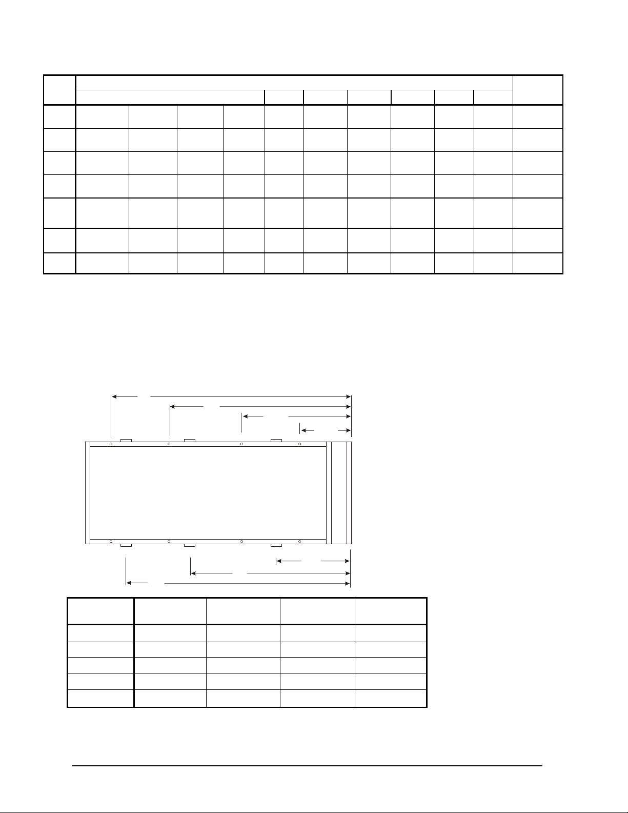
Table 8, Packaged, Standard Efficiency, Spring Isolators, Copper Fins
C
B
32.6
(826)
25.6
(650)
C
O
N
T
R
O
L
P
A
N
E
L
L2
D
E
UNIT SPRING-FLEX MOUNTINGS
SIZE M1 M2 M3 M4 M5 M6 M7 M8 M9 M10
225DS
250DS
275DS
300DS
330DS
350DS
360DS
390DS
400DS
450DS
1D -3600 1D -3600 1D -36000 1D-600 1D -3600 1D -3600
Green Green Green Green
1D -3600 1D -3600 1D -3600 1D -3600 1D-2040 1D-2040 1D-2040 1D-2040
Green Green Green Green Black Black Black Black
1D -3600 1D -3600 1D -3600 1D -3600 1D-2700 1D-2700 1D-2040 1D-2040
Green Green Green Green Purple Purple Black Black
1D 3600 1D -3600 1D -3600 1D -3600 1D-2700 1D-2700 1D-2040 1D-2040
Green Green Green Green Purple Purple Black Black
1D-3600 1D-3600 1D-3600 1D-3600 1D-3600 1D-3600 1D-2700 1D-2700 1D-2040 1D-2040
Green Green Green Green Green Green Purple Purple Black Black
1D-4800 1D-4800 1D-4800 1D-3600 1D-3600 1D-3600 1D-3600 1D-3600 1D-3600 1D-3600
Gray Gray Gray Gray Green Green Green Green Green Green
1D-4800 1D-4800 1D-4800 -1D-4800 1D-3600 1D-3600 1D-3600 1D-3600 1D-3600 1D-3600
Gray Gray Gray Gray Green Green Green Green Green Green
- Purple Purple
- -
- - 332320207
- - 332320208
- - 332320208
NOTE: Spring isolators have four (4) same-color springs per housing.
High Efficiency
KIT
NUMBER
332320201
332320204
332320209
332320209
Figure 3, Lifting and Isolator Locations, Model AGS 225DE – 300DE
View is looking down at base from above.
L3L5
M7 M3
M8 M4 M2M6
M5
L4L6
84.6
(2150)
L1
M1
AGS MODEL
225DE
250DE
260DE
275DE
300DE
B
in. (mm)
69.6 (1768) 255.9 (6500) 194.1 (4930) 253.2 (6431)
69.6 (1768) 250.1 (6353) 199.7 (5072) 288.6 (7330)
69.6 (1768) 250.1 (6353) 199.7 (5072) 288.6 (7330)
69.6 (1768) 266.4 (6767) 198.8 (5050) 324.0 (8230)
69.6 (1768) 266.4 (6767) 198.8 (5050) 324.0 (8230)
C
in. (mm)
D
in. (mm)
E
in. (mm)
8 IMM AGSD-2
Page 9
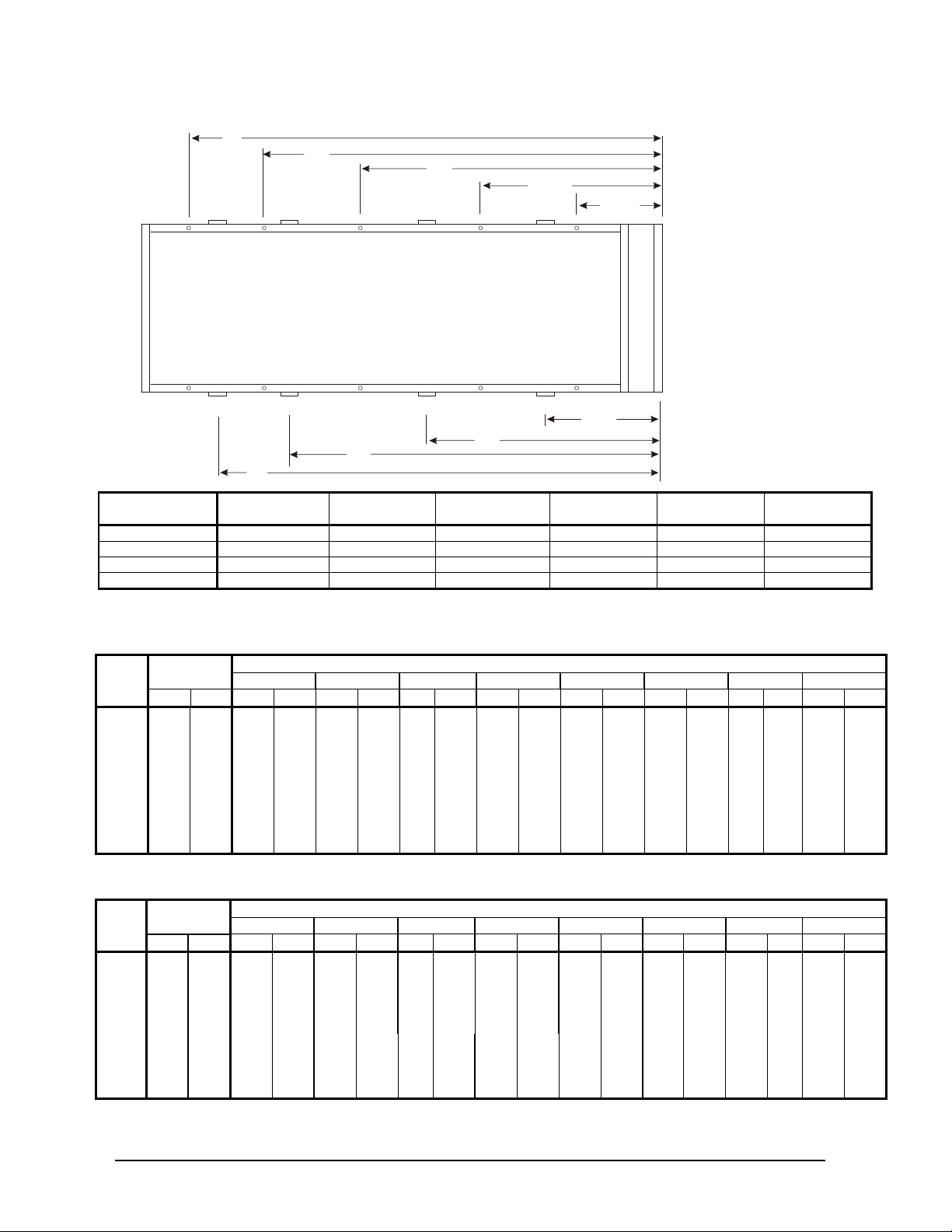
Figure 4, Lifting and Isolator Locations, Model AGS 330DE – 450DE
D
B
32.6
(826)
25.6
(650)
C
O
N
T
R
O
L
P
A
N
E
L
M2
L2
E
F
C
G
View is looking down at base from above.
L7
84.6
(2150)
L3L5
L1
M9
M10
AGS MODEL
330DE
350DE
400DE
450DE
M7 M3
M8 M4
L8
B
in. (mm)
M5
M6
C
in. (mm)
L4L6
D
in. (mm)
141.2 (3586) 262.0 (6655) 348.3 (8847) 177.0 (4496) 269.3 (6840) 361.6 (9185)
137.6 (3495)) 297.4 (7554) 383.8 (9749) 169.3 (4299) 304.7 (7739) 397.0 (10085)
137.6 (3495) 297.4 (7554) 383.8 (9749) 169.3 (4299) 304.7 (7739) 397.0 (10085)
137.6 (3495) 297.4 (7554) 419.2 (10648) 169.3 (4299) 304.7 (7739) 432.5 (10986)
M1
E
in. (mm)
Table 9, High Efficiency, Shipping and Lifting Weights, Aluminum Fins
UNIT
SIZE
225DE
250DE
260DE
275DE
300DE
330DE
350DE
400DE
450DE
WEIGHT.
L1 L2 L3 L4 L5 L6 L7 L8
lbs kg lbs kg lbs kg lbs kg lbs kg lbs kg lbs kg lbs kg lbs kg
12869 5843 2653 1204 2824 1282 2246 1020 2391 1086 1335 606 1420 645 - - - 13639 6192 2565 1165 2698 1225 2311 1049 2431 1104 1771 804 1863 845.8
14808 6723 2562 1163 2738 1243 2341 1063 2503 1136 1867 848 1997 907 - - - 14766 6704 2615 1187 2737 1243 2470 1121 2586 1174 2129 966.6 2229 1012
14808 6723 2547 1156 2708 1229 2440 1108 2595 1178 2189 994 2329 1057 - - - 20235 9187 3548 1611 3548 1611 2845 1292 2845 1292 2104 955 2104 955 1620 735 1620 735
21040 9552 3661 1662 3661 1662 3055 1387 3055 1387 2144 973 2144 973 1660 754 1660 754
21326 9682 3693 1677 3693 1677 3095 1405 3095 1405 2184 992 2184 992 1691 768 1691 768
22244 10099 3658 1661 3658 1661 3171 1440 3171 1440 2429 1103 2429 1103 1864 846 1864 846
LIFTING WEIGHT LBS (KG) SHIPPING
in. (mm)
F
- - - -
- - - -
G
in. (mm)
Table 10, High Efficiency, Shipping and Lifting Weights, Copper Fins
UNIT
SIZE
225DE
250DE
260DE
275DE
300DE
330DE
350DE
400DE
450DE
WEIGHT
L1 L2 L3 L4 L5 L6 L7 L8
lbs. kg lbs kg lbs kg lbs kg lbs kg lbs kg lbs kg lbs kg lbs kg
14709 6678 2660 1208 2810 1276 2550 1158 2695 1224 1986 902 2090 949 - - - 15741 7146 2915 1324 3048 1384 2661 1208 2781 1263 2121 963.1 2213 1005 - - - 16110 7314 2639 1198 2796 1269 2632 1195 2788 1266 2594 1178 2747 1247 - - - 17131 7777 3009 1366 3131 1421 2864 1300 2980 1353 2523 1146 2623 1191 - - - 17173 7797 2707 1229 2854 1296 2747 1247 2898 1316 2957 1342 3119 1416 - - - 23126 10499 3909 1775 3909 1775 3206 1456 3206 1456 2466 1120 2466 1120 1982 900 1982 900
24194 10984 4055 1841 4055 1841 3449 1566 3449 1566 2538 1152 2538 1152 2055 933 2055 933
24480 11114 4087 1855 4087 1855 3489 1584 3489 1584 2578 1170 2578 1170 2086 947 2086 947
25660 11650 4085 1855 4085 1855 3598 1633 3598 1633 2856 1297 2856 1297 2291 1040 2291 1040
IMM AGSD-2 9
LIFTING WEIGHT LBS (KG) SHIPPING
Page 10
Table 11, High Efficiency, Operating and Mounting Weights, Aluminum Fins
UNIT
SIZE
225DE
250DE
260DE
275DE
300DE
330DE
350DE
400DE
450DE
WEIGHT
lbs kg lbs kg lbs kg lbs kg lbs kg lbs kg lbs kg lbs kg lbs kg lbs kg lbs kg
13418 6092 2411 1095 2566 1165 2005 910 2134 969 1247 566 1328 603 836 380 891 405 - - - 14544 6603 2513 1141 2643 1200 2160 981 2273 1032 1473 669 1549 703 942 428 991 450
14913 6771 2514 1141 2687 1220 2177 988 2327 1056 1515 688 1620 735 1002 455 1071 486 - - - 15671 7115 2491 1131 2650 1203 2229 1012 2371 1076 1717 780 1826 829 1158 526 1231 559
15669 7114 2491 1131 2650 1203 2228 1012 2370 1076 1717 780 1826 829 1158 526 1231 559 - - - 21146 9600 2678 1216 2678 1216 2488 1130 2488 1130 2109 957 2109 957 1748 794 1748 794 1550 704 1550 704
21918 9951 2716 1233 2716 1233 2470 1121 2470 1121 2230 1012 2230 1012 1850 840 1850 840 1693 769 1693 769
22485 10208 2721 1235 2721 1235 2558 1161 2558 1161 2323 1055 2323 1055 1948 884 1948 884 1693 769 1693 769
23403 10625 2688 1220 2688 1220 2568 1166 2568 1166 2404 1091 2404 1091 2142 972 2142 972 1899 862 1899 862
M1 M2 M3 M4 M5 M6 M7 M8 M9 M10
ISOLATOR LOCATION WEIGHT OPERATING
Table 12, High Efficiency, Operating and Mounting Weights, Copper Fins
UNIT
SIZE
225DE
250DE
260DE
275DE
300DE
330DE
350DE
400DE
450DE
WEIGHT
lb kg lb kg lb kg lb kg lb kg lb kg lb kg lb kg lb kg lb kg lb kg
15258 6927 2643 1200 2798 1270 2234 1014 2363 1073 1475 670 1556 706 1068 485 1120 508 - - - 16646 7557 2776 1260 2905 1319 2422 1100 2536 1151 1736 788 1812 823 1205 547 1254 569
17015 7725 2789 1266 2962 1345 2450 1112 2600 1180 1788 812 1893 859 1277 580 1346 611 - - - 18036 8188 2787 1265 2946 1337 2524 1146 2666 1210 2013 914 2122 963 1455 661 1523 691
18034 8187 2787 1265 2946 1337 2524 1146 2666 1210 2013 914 2122 963 1454 660 1522 691 - - - 24037 10913 2967 1347 2967 1347 2777 1261 2777 1261 2398 1089 2398 1089 2037 925 2037 925 1839 835 1839 835
25072 11383 3031 1376 3031 1376 2785 1264 2785 1264 2545 1155 2545 1155 2165 983 2165 983 2010 913 2010 913
25639 11640 3036 1378 3036 1378 2873 1304 2873 1304 2638 1198 2638 1198 2263 1027 2263 1027 2008 912 2008 912
26819 12176 3030 1376 3030 1376 2910 1321 2910 1321 2746 1247 2746 1247 2484 1128 2484 1128 2240 1017 2240 1017
M1 M2 M3 M4 M5 M6 M7 M8 M9 M10
ISOLATOR LOCATION WEIGHT LBS (KG) OPERATING
- - - -
- - - -
- - - -
- - - -
High Efficiency, Isolator Identification
Table 13, Packaged, High Efficiency, Rubber-in-Shear Isolators, Aluminum Fins
UNIT MODEL
225DE, 250DE
260DE, 275DE
300DE
330DE
350DE
400DE
450DE
500DE
M1 M2 M3 M4 M5 M6 M7 M8 M9 M10
RP-4 RP-4 RP-4 RP-4 RP-4 RP-4 RP-4 RP-4 - -
Lime Lime Lime Lime
R-4 R-4 R-4 R-4 R-4 R-4 R-4 R-4 R-4 R-4
Lime Lime Lime Lime Lime Lime
R-4 R-4 R-4 R-4 R-4 R-4 R-4 R-4 R-4 R-4
Lime Lime Lime Lime Lime Lime Lime Lime
Table 14, Packaged, High Efficiency, Rubber-in-Shear Isolators, Copper Fins
UNIT MODEL
225DE, 250DE
260DE, 275DE
300DE
330DE
350DE
400DE
450DE
500DE
M1 M2 M3 M4 M5 M6 M7 M8 M9 M10
RP-4 RP-4 RP-4 RP-4 RP-4 RP-4 RP-4 RP-4 - -
Lime Lime Lime Lime
R-4 R-4 R-4 R-4 R-4 R-4 R-4 R-4 R-4 R-4
Charcoal Charcoal Charcoal Charcoal Lime Lime Lime Lime
R-4 R-4 R-4 R-4 R-4 R-4 R-4 R-4 R-4 R-4
Charcoal Charcoal Charcoal Charcoal Charcoal Charcoal Lime Lime Lime Lime
LOCATION
Brick
Red
LOCATION
Brick
Red
Brick
Red
Brown Brown - -
Brick
Red
Brick
Red
Brick
Red
Brown Brown
Brick
Red
Brick
Red
- -
Brick
Red
Brick
Red
Brick
Red
Brick
Red
KIT NUMBER
332325202
332325203
332325204
KIT NUMBER
332325202
332325205
332325206
10 IMM AGSD-2
Page 11

Table 15, Packaged, High Efficiency, Spring Isolators, Aluminum Fins
NOTES:
1.
2.
3. RP-4 MOUNT VERSION WITH STUD IN PLACE.
ALL DIMENSIONS ARE IN DECIMAL INCHES
3314814
1.13 ± .25
APPROX.
1.63
.38
DURULENE
MATERIAL
3.00
4.63
R
.28
TYP.
R
.250
TYP.
R.750 TYP.
RECESSED
ø
.500-13NC-2B
UNIT
SIZE
225DE
250DE
260DE
275DE
300DE
330DE
350DE
400DE
450DE
500DE
M1 M2 M3 M4 M5 M6 M7 M8 M9 M10
1D-3600 1D-3600 1D-3600 1D-3600 1D-2040 1D-2040 1D-1360 1D-1360
Green Green Green Green Black Black Red Red
1D-3600 1D-3600 1D-3600 1D-3600 1D-3600 1D-3600 1D-2040 1D-2040
Green Green Green Green Green Green Black Black
1D-3600 1D-3600 1D-3600 1D-3600 1D-3600 1D-3600 1D-2700 1D-2700 1D-2040 1D-2040
Green Green Green Green Green Green Purple Purple Black Black
1D-3600 1D-3600 1D-3600 1D-3600 1D-3600 1D-3600 1D-3600 1D-3600 1D-2700 1D-2700
Green Green Green Green Green Green Green Green Purple Purple
1D-3600 1D-3600 1D-3600 1D-3600 1D-3600 1D-3600 1D-3600 1D-3600 1D-3600 1D-3600
Green Green Green Green Green Green Green Green Green Green
NOTE: Spring isolators have four, same color springs per housing.
SPRING-FLEX MOUNTINGS, ALUMINUM FINS
Table 16, Packaged, High Efficiency, Spring Isolators, Copper Fins
UNIT SZE
M1 M2 M3 M4 M5 M6 M7 M8 M9 M10
225DE
250DE
260DE
275DE
300DE
330DE, 350DE
400DE, 450DE
500DE
1D-3600 1D-3600 1D-3600 1D-3600 1D-2040 1D-2040 1D-2040 1D-2040
Green Green Green Green Black Black Black Black
1D-3600 1D-3600 1D-3600 1D-3600 1D-2700 1D-2700 1D-2040 1D-2040
Green Green Green Green Purple Purple Black Black
1D-3600 1D-3600 1D-3600 1D-3600 1D-3600 1D-3600 1D-2040 1D-2040
Green Green Green Green Green Green Black Black
1D-4800 1D-4800 1D-4800 1D-4800 1D-3600 1D-3600 1D-3600 1D-3600 1D-3600 1D-3600
Gray Gray Gray Gray Green Green Green Green Green Green
NOTE: Spring isolators have four, same color springs per housing.
SPRING-FLEX MOUNTINGS, COPPER FINS
KIT NUMBER
- - 332320202
- - 332320203
332320204
332320205
332320206
KIT NUMBER
- - 332320207
- - 332320208
- - 332320203
332320209
Isolator Dimensions
Figure 5, Four-Spring Mounting Figure 6, RP-4, R-I-S Mounting
6.25
5.00
3.75
R4
3.87
.56 TYP.
VM&C
GRIP RIBS
IMM AGSD-2 11
MOUNT MATERIAL TO BE DURULENE RUBBER.
MOLDED STEEL AND ELASTOMER MOUNT FOR
OUTDOOR SERVICE CONDITIONS.
VM&C
R4
RAISED GRIP RIBS
DRAWING NUMBER
Page 12
Installation and Start-up
WARNING
Sharp edges and coil surfaces are a potential injury hazard. Avoid contact with them.
Note: Installation and maintenance are to be performed only by qualified personnel who are familiar
with local codes and regulations, and experienced with this type of equipment.
Start-up by McQuay Factory Service is included on all units sold for installation within the U.S. and
Canada and must be performed by them to initiate the standard Limited Product Warranty. Start-up by
any party other than McQuay Factory Service or a McQuay Authorized Service Representative will
void the Limited Product Warranty. Two-week prior notification of start-up is required. The
contractor should obtain a copy of the Start-up Scheduled Request Form from the sales representative
or from the nearest McQuay Factory Service office.
WARNING
Escaping refrigerant can displace air and cause suffocation. Immediately evacuate and ventilate the
equipment area. If the unit is damaged, follow Environmental Protection Agency (EPA) requirements.
Do not expose sparks, arcing equipment, open flame or other ignition source to the refrigerant.
Handling
Avoid rough handling shock due to impact or dropping the unit. Do not push or pull the unit.
Never allow any part of the unit to fall during unloading or moving, as this can result in serious
damage.
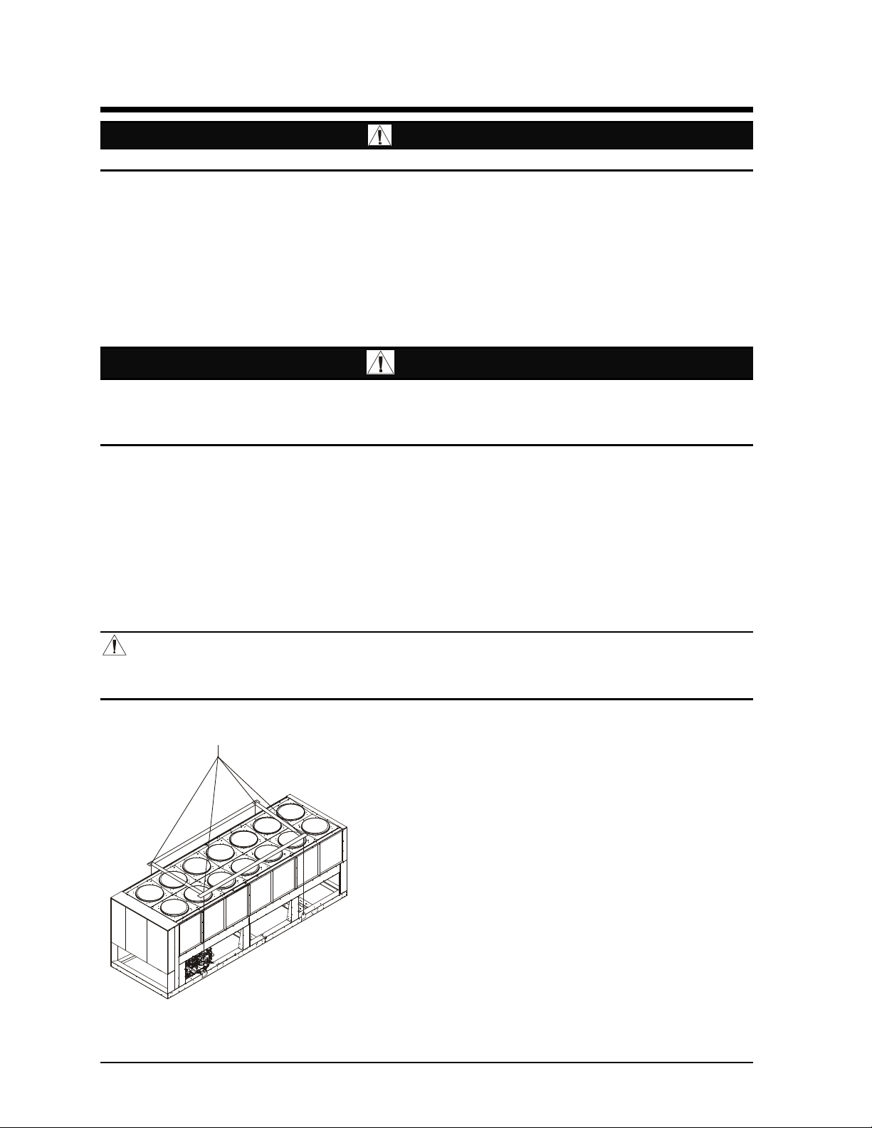
To lift the unit, lifting tabs with 2½" (64 mm) diameter holes are provided on the base of the unit. All
lifting holes must be used when lifting the unit. Spreader bars and cables should be arranged to
prevent damage to the condenser coils or unit cabinet (see Figure 7).
DANGER
Improper lifting or moving of a unit can result in property damage, severe
personal injury or death. Follow rigging and moving instructions carefully.
Figure 7, Required Lifting Method
NOTES:
1. All rigging points on a unit must be used. See location
and weights at lifting points beginning on page 5 for a
specific size unit.
2. Crosswise and lengthwise spreader bars must be used
to avoid damage to unit. Lifting cables from the unit
mounting holes up must be vertical.
3. The number of condenser sections, fans, and lifting
points can vary from this diagram.
Location
Locate the unit carefully to provide proper airflow to
the condenser. (See Figure 8 on page 14 for required
clearances.)
Due to the shape of the condenser coils on the AGS
chillers, it is recommended that the unit be oriented
so that prevailing winds blow parallel to the unit length, thus minimizing the wind effect on
12 IMM AGSD-2
Page 13

condensing pressure and performance. If low ambient temperature operation is expected, optional
louvers should be installed if the unit has no protection against prevailing winds.
Using less clearance than shown in Figure 8 can cause discharge air recirculation to the condenser and
could have a significant, detrimental effect on unit performance.
See Restricted Airflow beginning on page 15 for further information.
For pad-mounted units, it is recommended that the unit be raised a few inches with suitable supports
such as neoprene waffle vibration pads, located at least under the mounting locations. This will allow
water to drain from under the unit and facilitate cleaning under it.
Service Access
Compressors, filter-driers, and manual liquid line shutoff valves are accessible on each side or end of
the unit. The evaporator heater is located on the barrel.
The control panels are located on the end of the chiller. The left-hand control box contains the unit
and circuit microprocessors as well as transformers, fuses and terminal. The right-hand panel has line
voltage and contains a circuit breaker and starter for each compressor plus fuses, fan VFD (optional)
and fan contactors. A minimum of four feet of clearance is required in front of the panels.
The side clearance required for airflow provides sufficient service clearance.
On all AGS units, the condenser fans and motors can be removed from the top of the unit. The
complete fan/motor assembly can be removed for service. The fan blade must be removed for access
to wiring terminals at the top of the motor.
WARNING
Disconnect, lockout and tag all power to the unit before servicing condenser fan motors or
compressors. Failure to do so can cause bodily injury or death.
Do not block access to the sides or ends of the unit with piping or conduit. These areas must be open
for service access. Do not block any access to the control panels with a field-mounted disconnect
switches.
IMM AGSD-2 13
Page 14

Clearance Requirements
5ft (1.5m)
5ft (1.5m)
3ft (1m) for service
Air Flo
w
No obstructions allowed
above unit at any heigh
t
See notes 2 & 4
concerning wall
height at unit sides.
6ft (1.8m)
6ft (1.8m)
Figure 8, Clearance Requirements
if open fence or 50% open wall
if solid wall (see note 3 for pit)
4ft (1.2m)
For electric
panel access
if open fence or 50% open wall
if solid wall (see note 3 for pit)
No obstructions.
Recommended area
required for unit
operation, air flow
and maintenance
access.
See Note 5
Wall or
Fence
Notes:
1. Minimum side clearance between two units is 12 feet (3.7 meters).
2. Unit must not be installed in a pit or enclosure that is deeper or taller than the height of the unit unless extra
clearance is provided per note 4.
3. Minimum clearance on each side is 8 feet (2.4 meters) when installed in a pit no deeper than the unit height.
4. Minimum side clearance to a side wall or building taller than the unit height is 6 feet (1.8 meters), provided
no solid wall above 6 feet (1.8 meters) is closer than 12 feet (3.7 meters) to the opposite side of the unit.
5. Do not mount electrical conduits where they can block service access to compressor controls, refrigerant
driers or valves.
6. There must be no obstruction of the fan discharge.
7. Field installed switches must not interfere with service access or airflow.
8. The evaporator can be removed from the side of the unit and may require the temporary removal of a coil
section support post. See dimension drawings beginning on page 29 for details.
9. If the airflow clearances cannot be met, see the following pages on Restricted Airflow.
14 IMM AGSD-2
Page 15
Restricted Airflow
B
u
i
l
d
i
n
g
General
The clearances required for design operation of AGS air-cooled condensers are described in the
previous section. Occasionally, these clearances cannot be maintained due to site restrictions such as
units being too close together or a fence or wall restricting airflow, or both.
The McQuay AGS chillers have several features that can mitigate the problems attributable to
restricted airflow.
• The shape of the condenser section allows inlet air for these coils to come in from both sides and
the bottom. All the coils on one side serve one compressor. Every compressor always has its own
independent refrigerant circuit.
• The MicroTech II control is proactive in response to off-design conditions. In the case of single
or compounded influences restricting airflow to the unit, the microprocessor will act to keep the
compressor(s) running (at reduced capacity) as long as possible, rather than allowing a shut-off on
high discharge pressure.
Figure 9, Coil and Fan Arrangement
The following sections discuss the most common situations of condenser air restriction and give
capacity and power adjustment factors for each. Note that in unusually severe conditions, the
MicroTech II controller will adjust the unit operation to remain online until a less severe condition is
reached.
IMM AGSD-2 15
Page 16
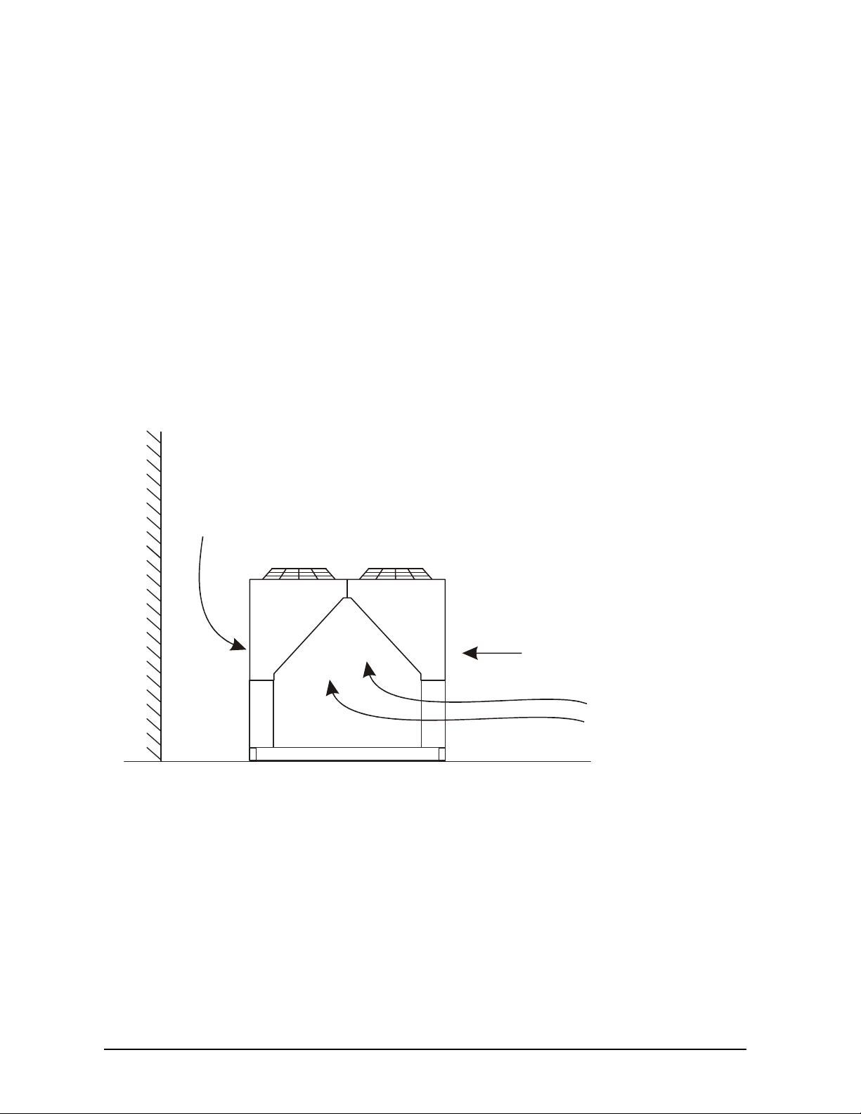
Case 1, Building or Wall on One Side of One Unit
5 ft.
(1.5m)
(1.8m)
The existence of a screening wall, or the wall of a building, in close proximity to an air-cooled chiller
is common in both rooftop and ground level applications. Hot air recirculation on the coils adjoining
the wall will increase compressor discharge pressure, decreasing capacity and increasing power
consumption.
When close to a wall, it is desirable to place chillers on the north or east side of them. It is also
desirable to have prevailing winds blowing parallel to the unit’s long axis. The worst case is to have
wind blowing hot discharge air into the wall.
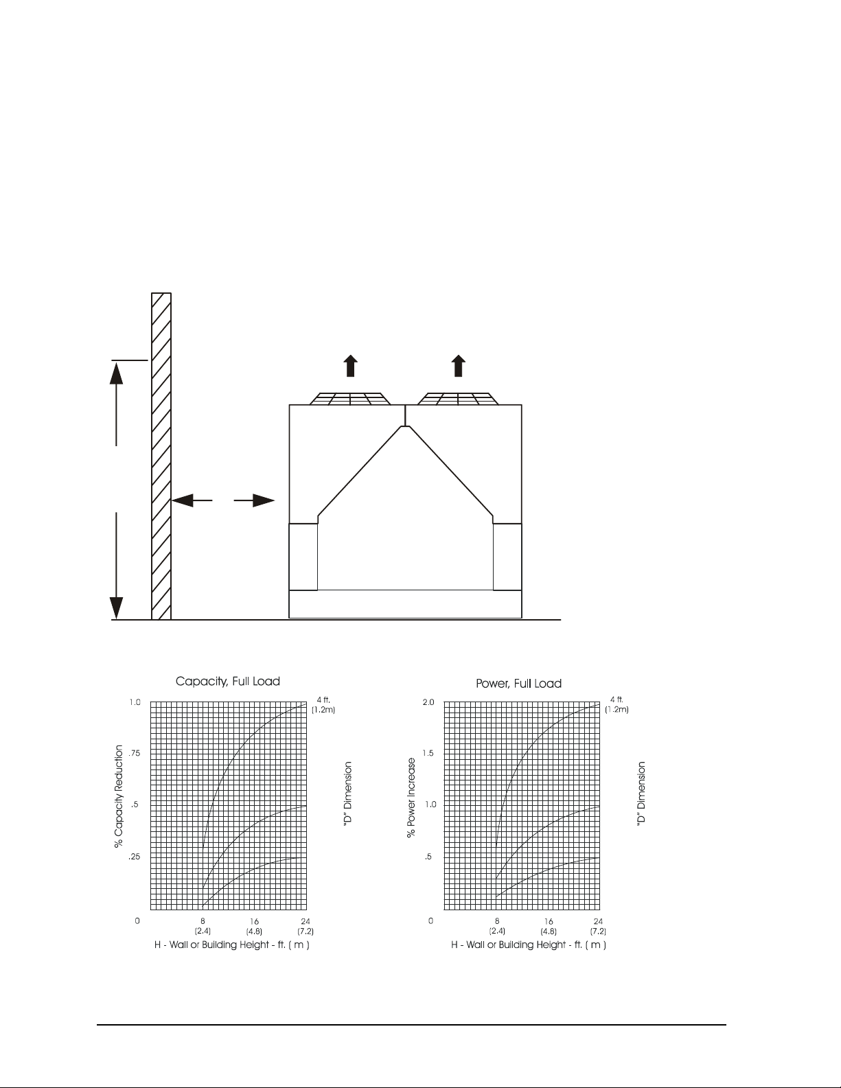
Figure 10, Unit Adjacent to Wall
H
D
Figure 11, Adjustment Factors
(1.5m)
6 ft.
(1.8m)
5 ft.
6 ft.
16 IMM AGSD-2
Page 17

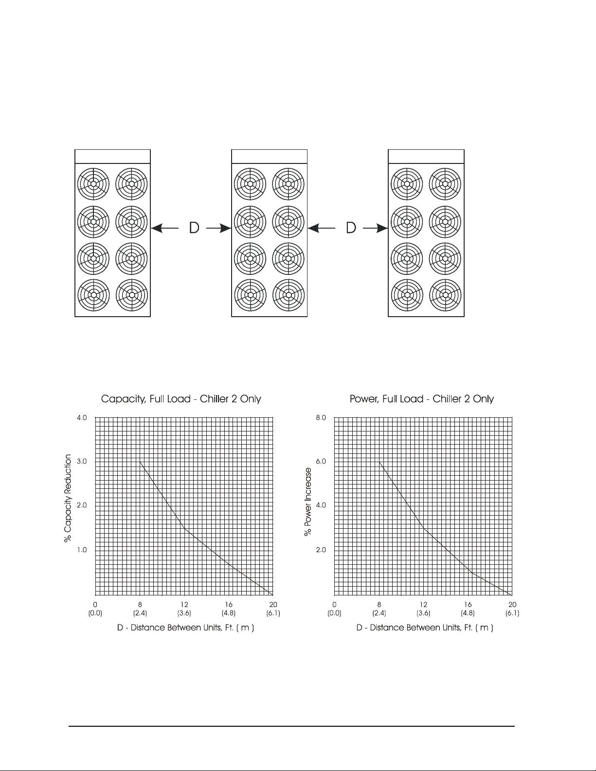
Case 2, Two Units Side By Side
Two or more units sited side by side are common. If spaced closer than 12 feet (3.7 meters), or 8 feet
(2.5 meters), depending on size, it is necessary to adjust the performance of each unit. Circuits
adjoining each other are affected. NOTE: This case applies only to two units side by side. See Case 3
for three or more parallel units. If one of the two units also has a wall adjoining it, see Case 1. Add
the two adjustment factors together and apply to the unit located between the wall and the other unit.
Mounting units end to end will not necessitate adjusting performance. Depending on the actual
arrangement, sufficient space must be left between the units for access to the control panel door
opening and/or evaporator tube removal. See “Clearance” section of this guide for requirements for
specific units.
Figure 12, Two Units Side by Side
Figure 13, Adjustment Factor
IMM AGSD-2 17
Page 18
Case 3, Three or More Units Side By Side
When three or more units are side by side, the outside units (chillers 1 and 3 in this case) are
influenced by the middle unit only on their inside circuits. Their adjustment factors will be the same
as Case 2. All inside units (only chiller 2 in this case) are influenced on both sides and must be
adjusted by the factors shown below.
Figure 14, Three or More Units
Chiller 1 Chiller 2 Chiller 3
Figure 15, Adjustment Factor
18 IMM AGSD-2
Page 19
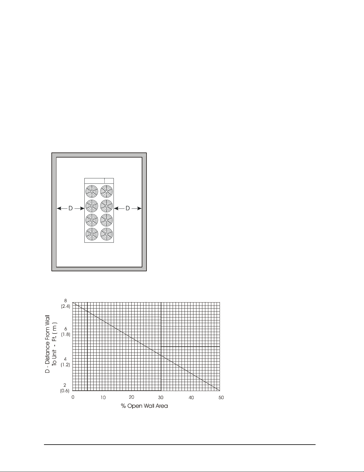
Case 4, Open Screening Walls
Decorative screening walls are often used to help conceal a unit either on grade or on a rooftop. These
walls should be designed such that the combination of their open area and distance from the unit do
not require performance adjustment. It is assumed that the wall height is equal to or less than the unit
height when mounted on its base support. This is usually satisfactory for concealment. If the wall
height is greater than the unit height, see Case 5, Pit Installation.
The distance from the ends of the unit to the end walls must be sufficient for service, opening control
panel doors, and pulling evaporator tubes, as applicable.
If each side wall is a different distance from the unit, the distances can be averaged, providing either
wall is not less than 8 feet (2.4 meters) from the unit. For example, do not average 4 feet and 20 feet
to equal 12 feet.
Figure 16, Open Screening Walls
Figure 17, Wall Free Area vs. Distance
IMM AGSD-2 19
Page 20
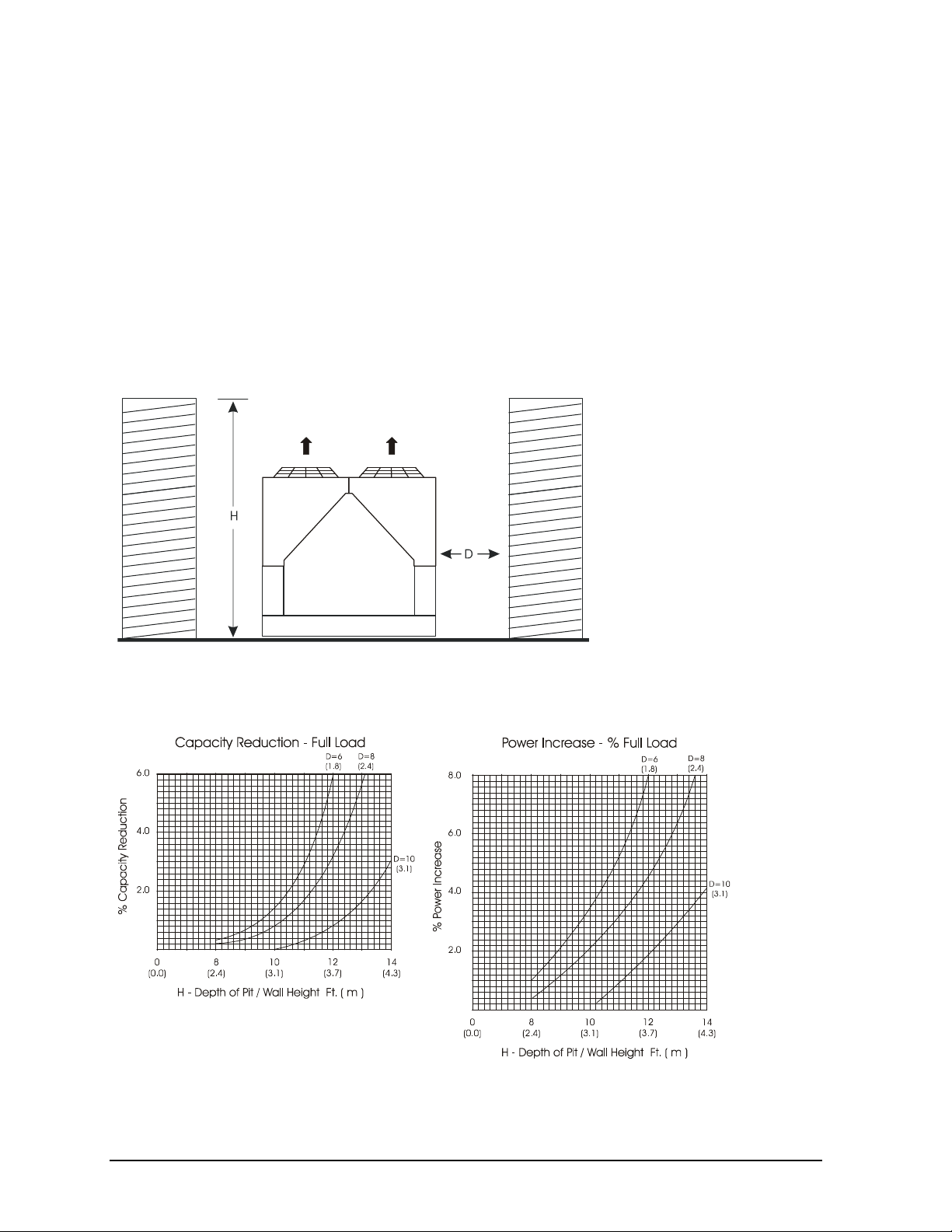
Case 5, Pit/Solid Wall Installation
Pit installations can cause operating problems and great care must be exercised if they are to be used
on an installation. Recirculation and restriction can both occur. A solid wall surrounding a unit is
substantially the same as a pit and the data presented in this case should be used.
Steel grating is sometimes used to cover a pit to prevent accidental falls or trips into the pit. The
grating material and installation design must be strong enough to prevent such accidents, yet provide
abundant open area or serious recirculation problems will occur. Have any pit installation reviewed by
the McQuay Factory Service prior to installation to discuss whether it has sufficient airflow
characteristics. The installation design engineer must approve the work and is responsible for design
criteria.
Figure 18, Pit Installation
Figure 19, Adjustment Factor
20 IMM AGSD-2
Page 21
Chilled Water
It is recommended that the chilled water pumps' starters be wired to, and controlled by, the chiller's
microprocessor. The controller will energize the pump whenever at least one circuit on the chiller is
enabled to run, whether there is a call for cooling or not. The control will also start the pump when
freezing temperatures are approached. Wiring connection points are shown in Figure 28 on page 48.
Water Piping
Due to the variety of piping practices, follow the recommendations of local authorities. They can
supply the installer with the proper building and safety codes required for a proper installation.
Design the piping with a minimum number of bends and changes in elevation to keep system cost
down and performance up. It should contain:
1. Vibration eliminators to reduce vibration and noise transmission to the building.
2. Shutoff valves to isolate the unit from the piping system during unit servicing.
3. Manual or automatic air-vent valves at the high points of the system and drains at the low parts in
the system. The evaporator should not be the highest point in the piping system.
4. Some means of maintaining adequate system water pressure (i.e., expansion tank or regulating
valve).
5. Water temperature and pressure indicators located at the evaporator inlet and outlet to aid in unit
servicing. Any connections should be made prior to filling the system with water.
6. A strainer to remove foreign matter from the water before it enters the pump. Place the strainer far
enough upstream to prevent cavitation at the pump inlet (consult pump manufacturer for
recommendations). The use of a strainer will prolong pump life and help maintain high system
performance levels.
NOTE
evaporator. This will aid in preventing foreign material from entering the evaporator and causing
damage or decreasing its performance. Care must also be exercised if welding pipe or flanges to the
evaporator connections to prevent any weld slag from entering the vessel. Units equipped with the
optional pump package will have a strainer in the pump suction.
7. Any water piping to the unit must be protected to prevent freeze-up if below freezing temperatures
:
A 20-mesh strainer must also be placed in the supply water line just prior to the inlet of the
are expected.
CAUTION
If a separate disconnect is used for the 115V supply to the unit, it should power the entire control
circuit. It should be clearly marked so that it is not accidentally shut off during cold seasons. Freeze
damage to the evaporator could result. If the evaporator is drained for winter freeze protection, the
heaters must be de-energized to prevent burnout.
8. If the unit is used as a replacement chiller on a previously existing piping system, flush the system
thoroughly prior to unit installation. Perform regular chilled water analysis and chemical water
treatment immediately at equipment start-up.
9. In the event glycol is added to the water system as a late addition for freeze protection, recognize
that the refrigerant suction pressure will be lower, cooling performance less, and water side
pressure drop greater. If the percentage of glycol is large, or if propylene is employed in lieu of
ethylene glycol, the added pressure drop and loss of performance could be substantial.
IMM AGSD-2 21
Page 22

10. For ice making or low temperature glycol operation, a different freezestat pressure value is usually
required. The freezestat setting can be manually changed through the MicroTech II controller.
Make a preliminary leak check prior to insulating the water piping and filling the system.
Include a vapor barrier with the piping insulation to prevent moisture condensation and possible
damage to the building structure. It is important to have the vapor barrier on the outside of the
insulation to prevent condensation within the insulation on the cold surface of the pipe.
System Water Volume
All chilled water systems need adequate time to recognize a load change, respond to that load change
and stabilize, without undesirable short cycling of the compressors or loss of control. In air
conditioning systems, the potential for short cycling usually exists when the building load falls below
the minimum chiller plant capacity or on close-coupled systems with very small water volumes.
Some of the things the designer should consider when looking at water volume are the minimum
cooling load, the minimum chiller plant capacity during the low load period and the desired cycle time
for the compressors.
Assuming that there are no sudden load changes and that the chiller plant has reasonable turndown, a
rule of thumb of “gallons of water volume equal to two to three times the chilled water gpm flow rate”
is often used.
A properly designed storage tank should be added if the system components do not provide sufficient
water volume.
Variable Speed Pumping
Variable water flow involves reducing the water flow through the evaporator as the load decreases.
McQuay chillers are designed for this duty, provided that the rate of change in water flow is slow, and
the minimum and maximum flow rates for the vessel are not exceeded.
The recommended maximum change in water flow is 10 percent of the change per minute. For
example, if the maximum (design) flow is 200 gpm and the flow is reduced to a minimum of 140 gpm,
the change in flow is 60 gpm, so the maximum change per minute would be 10% of 60, or 6 gpm per
minute. It would take ten minutes to change the flow through the entire range.
The water flow through the vessel must remain between the minimum and maximum values listed on
page 27. If flow drops below the minimum allowable, large reductions in heat transfer can occur. If
the flow exceeds the maximum rate, excessive pressure drop and tube erosion can occur.
Evaporator Freeze Protection
AGS chillers are equipped with thermostatically controlled evaporator heaters that help protect against
freeze-up down to -20°F (-28°C).
NOTE: The heaters come from the factory connected to the control power circuit. The control power
can be rewired in the field to a separate 115V supply (do not wire directly to the heater). See the field
wiring diagram on page 48. If this is done, mark the disconnect switch clearly to avoid accidental
deactivation of the heater during freezing temperatures. Exposed chilled water piping also requires
protection.
For additional protection, at least one of the following procedures should be used during periods of
sub-freezing temperatures:
1. Adding of a concentration of a glycol anti-freeze with a freeze point 10 degrees F. below the
lowest expected temperature. This will result in decreased capacity and increased pressure drop.
22 IMM AGSD-2
Page 23
Note: Do not use automotive grade antifreezes as they contain inhibitors harmful to chilled water
systems. Use only glycols specifically designated for use in building cooling systems.
2. Draining the water from outdoor equipment and piping and blowing the chiller tubes dry from the
chiller. Do not energize the chiller heater when water is drained from the vessel.
CAUTION
If fluid is absent from the evaporator, the evaporator heater must be de-energized to avoid burning out
the heater or causing damage from the high temperatures.
1. Providing operation of the chilled water pump, circulating water through the chilled water system
and through the evaporator.
Table 17, Freeze Protection
Temperature
°°°°F (°°°°C)
20 (6.7) 16 18 11 12
10 (-12.2) 25 29 17 20
0 (-17.8) 33 36 22 24
-10 (-23.3) 39 42 26 28
-20 (-28.9) 44 46 30 30
-30 (-34.4) 48 50 30 33
-40 (-40.0) 52 54 30 35
-50 (-45.6) 56 57 30 35
-60 (-51.1) 60 60 30 35
Notes:
1. These figures are examples only and cannot be appropriate to every situation. Generally, for an extended
margin of protection, select a temperature at least 15°F lower than the expected lowest ambient temperature.
Inhibitor levels should be adjusted for solutions less than 25% glycol.
2. Glycol of less than 25% concentration is not recommended because of the potential for bacterial growth and
loss of heat transfer efficiency.
For Freeze Protection For Burst Protection
Ethylene Glycol Propylene Glycol Ethylene Glycol Propylene Glycol
Percent Volume Glycol Concentration Required
IMM AGSD-2 23
Page 24
Operating Limits:
Maximum standby ambient temperature, 130°F (55°C)
Maximum operating ambient temperature, 105°F. See High Ambient Option below.
Minimum operating ambient temperature (standard), 35°F (2°C)
Minimum operating ambient temperature (optional low-ambient control), 0°F (-18°C)
Leaving chilled water temperature, 40°F to 60°F (4°C to 16°C)
Leaving chilled fluid range (with anti-freeze), 20°F to 60°F (-7°C to 16°C). Unloading is not permitted
with fluid leaving temperatures below 30°F (-1°C).
Operating Delta-T range, 6 degrees F to 16 degrees F (10.8°C to 28.8°C)
Maximum operating inlet fluid temperature, 76°F (24°C)
Maximum startup inlet fluid temperature, 90°F (32°C)
Maximum non-operating inlet fluid temperature, 100°F (38°C)
NOTE: Contact the local McQuay sales office for operation outside any of these limits.
High Ambient Option, A factory-installed option that allows operation in high ambient temperature
locations with operating temperatures above 105°F up to 125°F (40.6°C to 51.7°C).
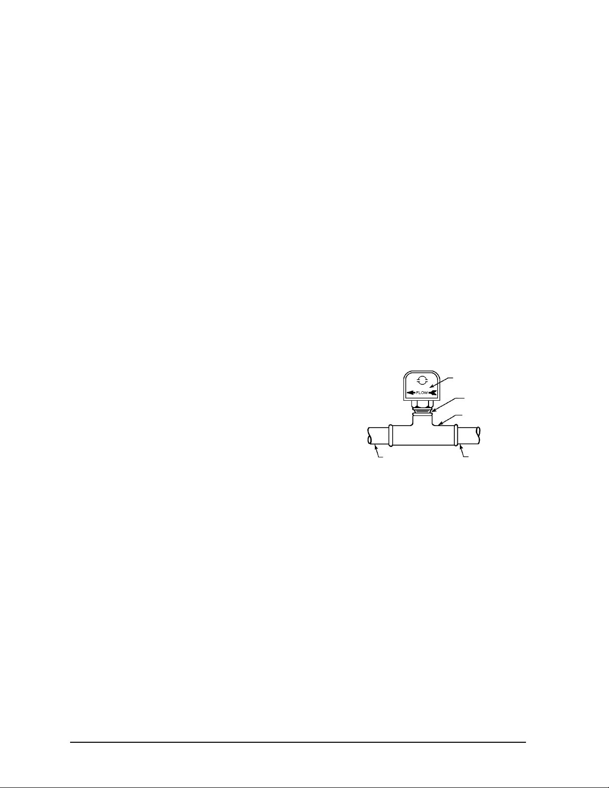
Flow Switch
A flow switch must be included in the chilled water
system to prove that there is adequate water flow to the
evaporator before the unit can start. It also serves to shut
down the unit in the event that water flow is interrupted in
order to guard against evaporator freeze-up.
A solid state, thermal dispersion flow switch that is
factory-mounted in the chiller leaving water nozzle and
factory-wired is available as an option.
Figure 20, Flow Switch
Flow direction marked
on switch
1" (25mm) NPT flow
switch connection
Tee
A paddle-type flow switch for field mounting and wiring
in the leaving chilled water is also available as an option
from McQuay under ordering number 017503300. It is
1 1/4" (32mm) pipe
dia. min. after switch
1 1/4" (32mm) pipe
dia. min. before switch
adaptable to any pipe size from 1" (25mm) to 8" (203mm) nominal.
Certain minimum flow rates are required to close the switch and are listed in Table 18. Installation should
be as shown in Figure 17.
Electrical connections in the unit control center should be made at terminals 60 and 67 from switch
terminals Y and R. The normally open contacts of the flow switch should be wired between these two
terminals. Flow switch contact quality must be suitable for 24 VAC, low current (16ma). Flow switch
wire must be in separate conduit from any high voltage conductors (115 VAC and higher) and have an
insulation rating of 600 volts.
24 IMM AGSD-2
Page 25
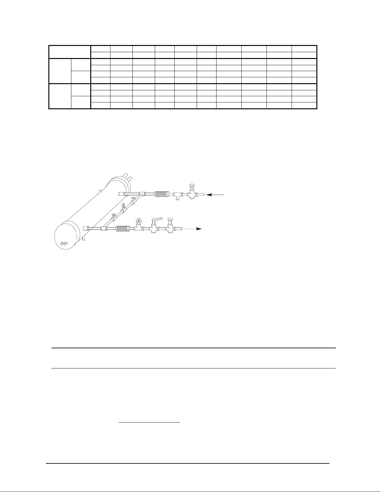
Table 18, Paddle Type Flow Switch Flow Rates
Vent
Valve
Vibration
Valved
Against Freezing
Vibration
Valve
Valve
()()(
)
(NOTE !)
Min.
Adjst.
Max.
Adjst.
Flow
Flow Lpm 0.8 1.1 2.2 2.8 4.3 11.4 22.9 35.9 38.6
Flow
Flow Lpm 2.8 4.1 6.1 7.3 11.4 27.7 53.4 81.8 90.8
NOTES:
1. A segmented 3-inch paddle (1, 2, and 3 inches) is furnished mounted, plus a 6-inch paddle loose.
2. Flow rates for a 2-inch paddle trimmed to fit the pipe.
3. Flow rates for a 3-inch paddle trimmed to fit the pipe.
4. Flow rates for a 3-inch paddle.
5. Flow rates for a 6-inch paddle.
inch 1 1/4 1 1/2 2 2 1/2 3 4 5 6 8 Pipe Size
mm 32 (2) 38 (2) 51 63 (3) 76 102 (4) 127 (4) 153 (4) 204 (5)
gpm 5.8 7.5 13.7 18.0 27.5 65.0 125.0 190.0 205.0
Lpm 1.3 1.7 3.1 4.1 6.2 14.8 28.4 43.2 46.6
gpm 3.7 5.0 9.5 12.5 19.0 50.0 101.0 158.0 170.0
No
gpm 13.3 19.2 29.0 34.5 53.0 128.0 245.0 375.0 415.0
Lpm 3.0 4.4 6.6 7.8 12.0 29.1 55.6 85.2 94.3
gpm 12.5 18.0 27.0 32.0 50.0 122.0 235.0 360.0 400.0
No
Figure 21, Typical Field Water Piping
Suction
In
Gauge
Flow
Eliminator
Balancing
Pressure
Out
Liquid
Drain
Notes:
1. Connections for vent and drain fittings are located on the top and bottom of the evaporator.
2. Piping must be supported to avoid putting strain on the evaporator nozzles.
Eliminator
Switch
Water
Strainer
Gate
Flow
Gate
Protect All Field Piping
Flow
Refrigerant Charge
All packaged units are designed for use with R-134a and are shipped with a full operating charge. The
operating charge for each unit is shown in the Physical Data Tables beginning on page 28.
Glycol Solutions
When using glycol anti-freeze solutions, the chiller's capacity, glycol solution flow rate, and pressure
drop through the evaporator can be calculated using the following formulas and tables.
Note: The procedure below does not specify the type of glycol. Use the derate factors found in Table
19 for corrections when using propylene glycol and those in Table 20 for ethylene glycol.
1. Capacity - Cooling capacity is reduced from that with plain water. To find the reduced value,
multiply the chiller’s water system tonnage by the capacity correction factor to find the chiller’s
capacity when using glycol.
2. Flow - To determine flow (or Delta-T) knowing Delta-T (or flow) and capacity:
GPM−=
24
factorflowtons
TDelta
3. Pressure drop - To determine pressure drop through the evaporator when using glycol, enter the
water pressure drop curve at the water flow rate. Multiply the water pressure drop found there by
the "PD" factor to obtain corrected glycol pressure drop.
IMM AGSD-2 25
Page 26
4. Power - To determine glycol system kW, multiply the water system kW by the factor designated
"Power".
Test coolant with a clean, accurate glycol solution hydrometer (similar to that found in service
stations) to determine the freezing point. Obtain percent glycol from the freezing point table below.
On glycol applications, the supplier normally recommends that a minimum of 25% solution by weight
be used for protection against corrosion or that additional inhibitors should be employed.
NOTE: Do not use automotive grade antifreeze. Industrial grade glycols must be used. Automotive
antifreeze contains inhibitors that will cause plating on the copper tubes within the chiller evaporator.
The type and handling of glycol used must be consistent with local codes.
Table 19, Ethylene Glycol Factors
Freeze
%
E.G.
10
20
30
40
50
Point
oF o
26 -3.3 0.996 0.998 1.036 1.097
18 -7.8 0.988 0.994 1.061 1.219
7 -13.9 0.979 0.991 1.092 1.352
-7 -21.7 0.969 0.986 1.132 1.532
-28 -33.3 0.958 0.981 1.182 1.748
Capacity Power Flow PD
C
Table 20, Propylene Glycol Factors
Freeze
% P.G.
10
20
30
40
50
Point
oF o
26 -3.3 0.991 0.996 1.016 1.092
19 -7.2 0.981 0.991 1.032 1.195
9 -12.8 0.966 0.985 1.056 1.345
-5 -20.6 0.947 0.977 1.092 1.544
-27 -32.8 0.932 0.969 1.140 1.906
Capacity Power Flow PD
C
Water Flow and Pressure Drop
Adjust the chilled water flow through the evaporator to meet specified conditions. The flow rates
must fall between the minimum and maximum values shown in the table on the following page. Flow
rates below the minimum values shown can result in laminar flow that will reduce efficiency, cause
erratic operation of the electronic expansion valve and could cause low temperature cutouts. On the
other hand, flow rates exceeding the maximum values shown can cause erosion on the evaporator
water connections and tubes.
Measure the chilled water pressure drop through the evaporator at field-installed pressure taps. It is
important not to include valve or strainer pressure drops in these readings.
26 IMM AGSD-2
Page 27

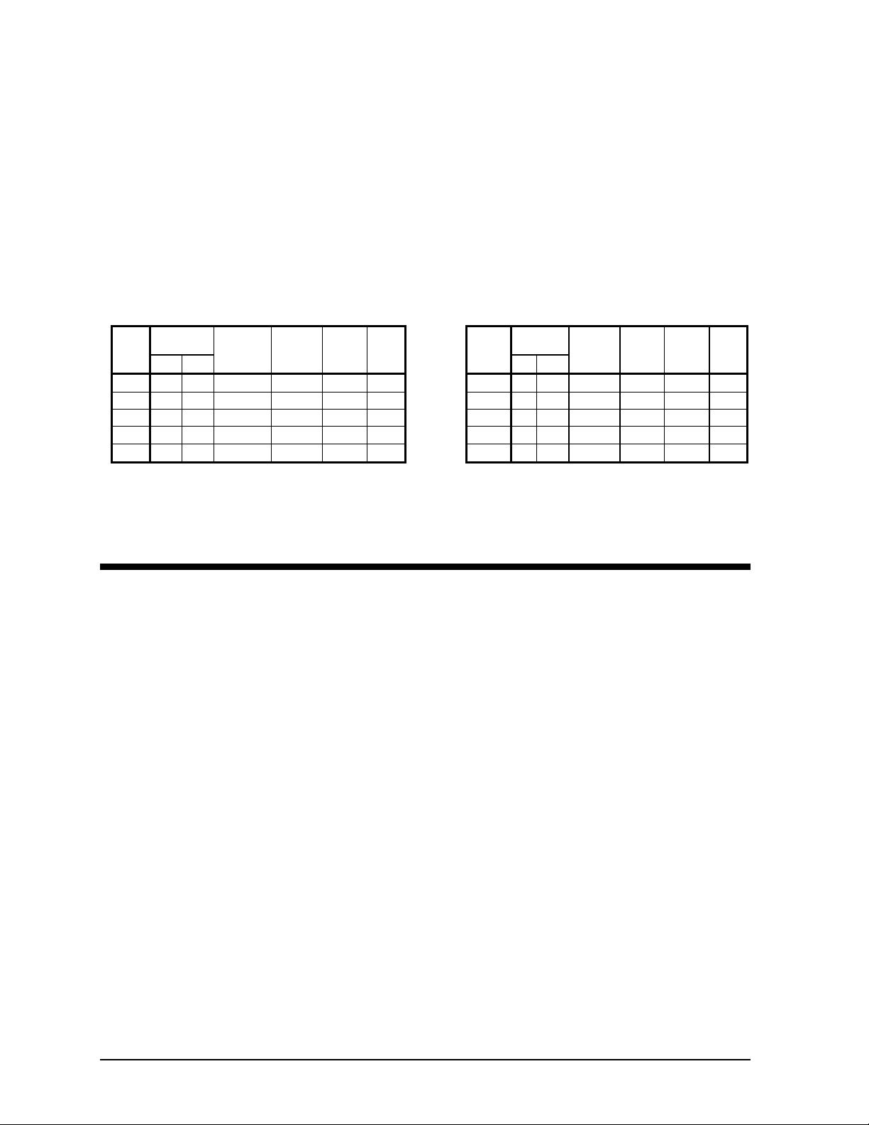
Figure 22, Standard Efficiency, Evaporator Pressure Drop
Standard Efficiency, Minimum/Nominal/Maximum Flow Rates
MODEL
225DS A
250DS A
275DS B
300DS C
330DS D
350DS D
360DS E
390DS E
400DS F
450DS F
CURVE
MINIMUM FLOW NOMINAL FLOW MAXIMUM FLOW AGS
GPM FT L/S KPA GPM FT L/S KPA GPM FT L/S KPA
252 3.9 15.9 11.6 507 14.3 32.0 42.6 845 37.0 53.3 110.3
252 3.9 15.9 11.6 556 17.0 35.1 50.7 926 43.0 58.5 128.1
292 2.2 18.4 6.6 631 9.5 39.8 28.3 1052 26.5 66.4 79.0
355 3.7 22.4 11.0 713 12.2 45.0 36.4 1188 33.3 75.0 99.2
356 2.7 22.5 8.0 765 11.4 48.3 34.0 1275 30.0 80.4 89.4
356 2.7 22.5 8.0 809 12.6 51.1 37.5 1349 34.0 85.1 101.3
407 3.9 25.7 11.6 843 15.4 53.2 45.9 1404 40.0 88.6 119.2
407 3.9 25.7 11.6 896 17.3 56.5 51.6 1493 45.0 94.2 134.1
470 3.3 29.7 9.8 937 12.2 59.1 36.4 1562 32.0 98.6 95.4
470 3.3 29.7 9.8 1044 15.0 65.9 44.7 1740 37.0 109.8 110.3
IMM AGSD-2 27
Page 28

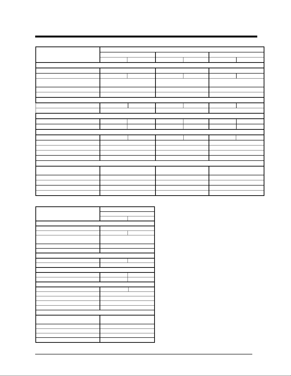
Figure 23, High Efficiency, Evaporator Pressure Drops
High Efficiency, Minimum/Nominal/Maximum Flow Rates
MODEL
225DE A
250DE A
260DE B
275DE B
300DE C
330DE D
350DE E
400DE F
450DE F
CURVE
MINIMUM FLOW NOMINAL FLOW MAXIMUM FLOW AGS
gpm ft l/s kpa gpm ft l/s kpa gpm ft l/s kpa
260 2.3 16.4 6.9 516 8.7 32.5 25.9 860 23.4 54.2 69.7
260 2.3 16.4 6.9 565 10.4 35.7 31.0 942 28.0 59.4 83.4
292 2.2 18.4 6.6 599 8.7 37.8 25.9 998 23.5 63.0 70.0
292 2.2 18.4 6.6 642 9.8 40.5 29.2 1070 26.5 67.5 79.0
355 3.6 22.4 10.7 719 13.4 45.3 39.9 1198 36.0 75.6 107.3
356 2.6 22.5 7.7 778 11.4 49.1 34.0 1296 28.0 81.8 83.4
407 3.9 25.7 11.6 823 15.0 51.9 34.0 1372 38.4 86.5 114.4
470 3.2 29.7 9.5 953 12.1 60.2 44.7 1589 31.0 100.3 92.4
470 3.2 29.7 9.5 1051 14.5 66.3 36.1 1751 38.1 110.5 113.5
28 IMM AGSD-2
Page 29
Physical Data, Standard Efficiency
Table 21, Standard Efficiency, AGS 225DS – AGS 275DS
DATA
BASIC DATA
Unit Cap. @ ARI tons (kW) 211.2 (742.6) 231.6 (814.3) 263.1 (925.1)
Unit Operating Charge lbs (kg) 185 (84) 185 (84) 210 (95) 210 (95) 210 (95) 240 (109)
Cabinet Dimensions
L x W x H, in. (mm)
Unit Operating Weight, lbs. (kg) 12556 (5700) 13398 (6069) 14958 (6785)
Unit Shipping Weight, lbs (kg) 12007 (5451) 12849 (5821) 14049 (6374)
COMPRESSORS, SCREW, SEMI-HERMETIC
Nominal Capacity, tons (kW) 100 (350) 100 (350) 100 (350) 125 (4370 125 (4370 150 (525)
Minimum Capacity (% of Full Load) 15 15 15
CONDENSERS, HIGH EFFICIENCY FIN AND TUBE TYPE WITH INTEGRAL SUBCOOLER
Pumpdown Capacity, lbs (kg) 249 (113) 249 (113) 287 (130) 287 (130) 287 (130) 325 (148)
Coil Inlet Face Area, sq. ft. (sq m.) 129.2 (12.0) 129.2 (12.0) 150.8 (14.0) 150.8 (14.0) 150.8 (14.0) 172.5 (16.0)
CONDENSER FANS, DIRECT DRIVE PROPELLER TYPE
No. of Fans/Circuit – 30 in. Fan Dia. 6 6 7 7 8 8
Fan Motor hp (kW) 2.5 (1.8) 2.5 (1.8) 2.5 (1.8)
Fan & Motor RPM, 60Hz 1140 1140 1140
60 Hz Fan Tip Speed, fpm (m/s)
60 Hz Total Unit Airflow, cfm (l/s) 137328 (64819) 160216 (75622) 183104 (86425)
EVAPORATOR, DIRECT EXPANSION SHELL AND TUBE
Shell Dia.-Tube Length
in.(mm) - in. (mm)
Connection Size, in (mm) 6 (152) 6 (152) 8 (203)
Water Volume, gallons (liters) 65.8 (249.4) 65.8 (249.4) 108.5 (411.1)
Max. Water Pressure, psi (kPa) 152 (1048) 152 (1048) 152 (1048)
Max. Refrigerant Press., psi (kPa) 350 (2413) 350 (2413) 350 (2413)
225DS 250DS 275DS
Ckt 1 Ckt 2 Ckt 1 Ckt 2 Ckt 1 Ckt 2
243x88x97
(6172x2225x2464)
8954 (45)
16x108 (406x2750) 16x108 (406x2750) 20x108 (508x2750)
AGS-DS MODEL NUMBER
279x88x97
(7087x2225x2464)
8954 (45)
314x88x97
(7984x2225x2464)
8954 (45)
Table 22, Standard Efficiency, AGS 300DS
DATA
BASIC DATA
Unit Cap. @ ARI, tons (kW) 297.0 (1042.5)
Unit Operating Charge lbs (kg) 240 (109) 240 (109)
Cabinet Dimensions
L x W x H, in. (mm)
Unit Operating Weight (1), lbs. (kg) 14903 (6751)
Unit Shipping Weight(1), lbs (kg) 14954 (6760)
COMPRESSORS, SCREW, SEMI-HERMETIC
Nominal Capacity, tons (kW) 150 (525) 150 (525)
Minimum Capacity (% of Full Load) 15
CONDENSERS, HIGH EFFICIENCY FIN AND TUBE TYPE
Pumpdown Capacity, lbs (kg) 325 (148) 325 (148)
Coil Inlet Face Area, sq. ft. (sq m.) 172.5 (16.0) 172.5 (16.0)
CONDENSER FANS, DIRECT DRIVE PROPELLER TYPE
No. of Fans/Circuit – 30 in. Fan Dia 8 8
Fan Motor -- hp (kW) 2.5 (1.8)
Fan & Motor RPM, 60Hz 1140
60 Hz Fan Tip Speed, fpm (m/s)
60 Hz Total Unit Airflow, cfm (l/s) 183104 (86425)
EVAPORATOR, DIRECT EXPANSION SHELL AND TUBE
Shell Dia.-Tube Length
in.(mm) - in. (mm)
Connection Size, in (mm) 8 (203)
Water Volume, gallons (liters) 103.2 (391.2)
Max. Water Pressure, psi (kPa) 152 (1048)
Max. Refrigerant Press., psi (kPa) 350 (2413)
AGS MODEL NUMBER
300DS
Ckt 1 Ckt 2
314x88x97
(7984x2225x2464)
8954 (45)
20x108 (508x2750)
IMM AGSD-2 29
Page 30
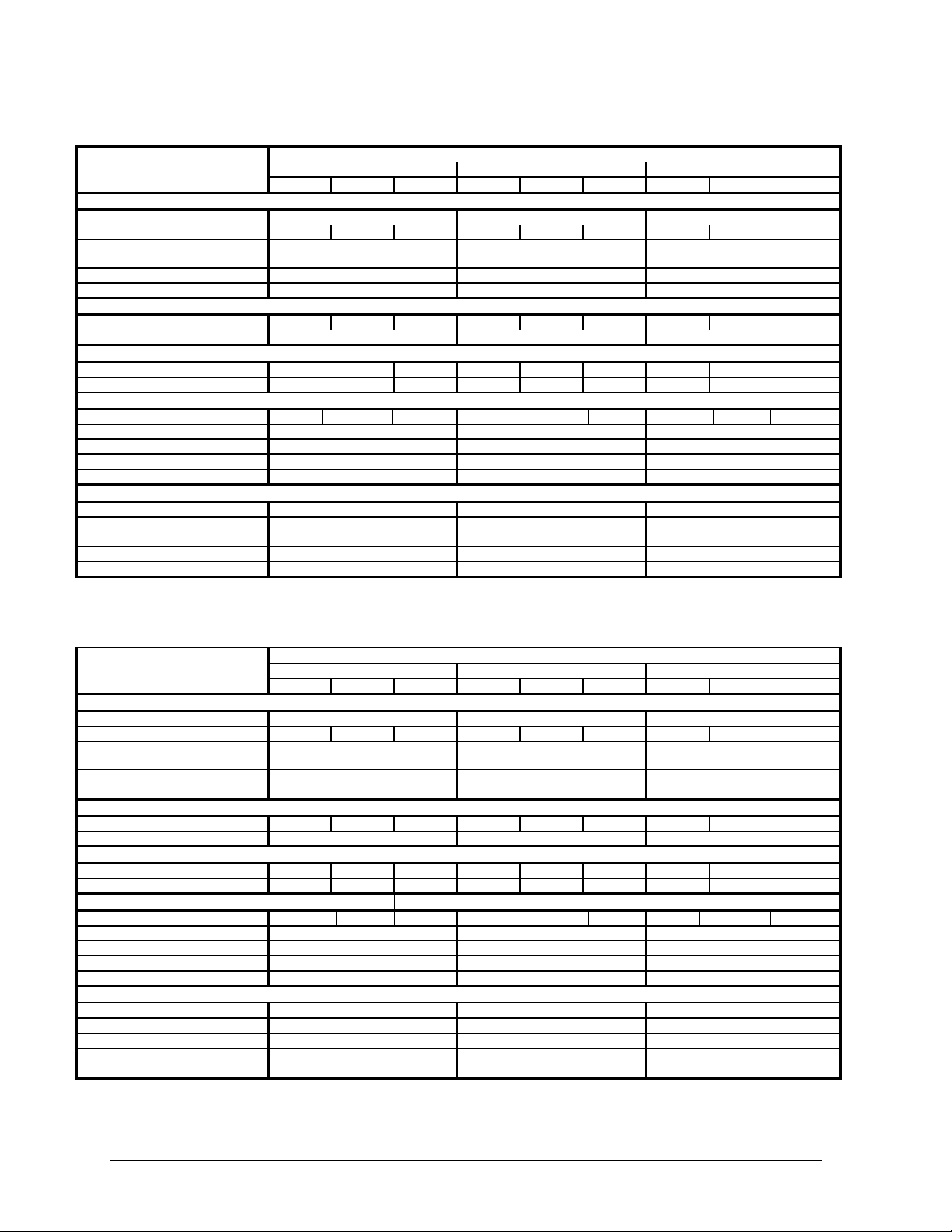
Table 23, Standard Efficiency, AGS 330DS – AGS 360DS
DATA
Ckt. 1 Ckt. 2 Ckt. 3 Ckt. 1 Ckt. 2 Ckt. 3 Ckt. 1 Ckt. 2 Ckt. 3
BASIC DATA
Unit Cap. @ ARI, tons (kW) 318.7 (1120.5) 337.2 (1185.6) 351.1 (1234.5)
Unit Operating Charge, lbs (kg) 210 (95) 210 (95) 190 (86 210 (95) 210 (95) 190 (86) 210 (95) 210 (95) 190 (86)
Cabinet Dim.,
L x W x H, in. (mm)
Operating Weight(1), lbs. (kg) 20507 (9302) 20507 (9302) 20517 (9307)
Shipping Weight(1), lbs (kg) 19596 (8889) 19596 (8889) 19639 (8908)
COMPRESSORS, SCREW, SEMI-HERMETIC
Nominal Capacity, tons (kW) 100 (350) 100 (350) 100 (350) 100 (350) 125 (437) 100 (350) 125 (437) 125 (437) 100 (350)
Minimum Capacity (% of Full Load)
CONDENSERS, HIGH EFFICIENCY FIN AND TUBE TYPE WITH INTEGRAL SUBCOOLER
Pumpdown Capacity, lbs (kg) 287 (130) 287 (130) 243 (110) 287 (130) 287 (130) 243 (110) 287 (130) 287 (130) 243 (110)
Coil Inlet Face Area, sq. ft. (sq m.) 150.8 (14) 150.8 (14) 128.5 (12) 150.8 (14) 150.8 (14) 128.5 (12) 150.8 (14) 150.8 (14) 128.5 (12)
CONDENSER FANS, DIRECT DRIVE PROPELLER TYPE
No. of Fans/Cir, Fan Dia. 30 in 7 7 6 7 7 6 7 7 6
Fan Motor -- hp (kW) 2.5 (1.8) 2.5 (1.8) 2.5 (1.8)
Fan & Motor RPM, 60Hz 1140 1140 1140
60 Hz Fan Tip Speed, fpm (m/s)
60 Hz Total Unit Airflow, cfm (l/s) 228880 (108031) 228880 (108031) 228880 (108031)
EVAPORATOR, DIRECT EXPANSION SHELL AND TUBE
Shell Dia.,Tube Length in.(mm) 20x108 (508x2750) 20x108 (508x2750) 20x108 (508x2750)
Connection Size, in (mm) 8 (203) 8 (203) 8 (203)
Water Volume, gallons (liters) 107.0 (405.4) 107.0 (405.4) 103.2 (391.2)
Max. Water Pressure, psi (kPa) 152 (1048) 152 (1048) 152 (1048)
Max. Refrigerant Press., psi (kPa) 350 (2413) 350 (2413) 350 (2413)
330DS 350DS 360DS
403x88x97
(10239x2225x2459)
10 10 10
8954 (45)
AGS MODEL NUMBER
403x88x97
(10239x2225x2459)
8954 (45)
403x88x97
(10239x2225x2459)
8954 (45)
Table 24, Standard Efficiency, AGS 390DS – AGS 450DS
AGS MODEL NUMBER
DATA 390DS 400DS 450DS
Ckt. 1 Ckt. 2 Ckt. 3 Ckt. 1 Ckt. 2 Ckt. 3 Ckt. 1 Ckt. 2 Ckt. 3
BASIC DATA
Unit Cap. @ ARI, tons (kW) 373.2 (1311.8) 390.4 (1373.3)) 434.8 (1529.1)
Unit Operating Charge, lbs (kg) 210 (95) 210 (95) 230 (104) 215 (97) 215 (97) 235 (106) 240 (109) 240 (109) 240 (109)
Cabinet Dim., L x W x H, in. (mm)
Operating Weight(1), lbs. (kg) 21156 (9596) 21708 (9847) 22485 (10199)
Shipping Weight(1), lbs (kg) 20278 (9198) 20549 (9321) 21326 (9674)
COMPRESSORS, SCREW, SEMI-HERMETIC
Nominal Capacity, tons (kW) 125 (437) 125 (437) 125 (437) 125 (437) 125 (437) 150 (525) 150 (525) 150 (525) 150 (525)
Minimum Capacity (% of Full Load)
CONDENSERS, HIGH EFFICIENCY FIN AND TUBE TYPE WITH INTEGRAL SUBCOOLER
Pumpdown Capacity, lbs (kg) 287 (130) 287 (130) 316 (144) 287 (130) 287 (130) 316 (144) 325 (147) 325 (147) 316 (144)
Coil Inlet Face Area, sq. ft. (sq m.) 150.8 (14) 150.8 (14) 171.7 (16) 150.8 (14) 150.8 (14) 171.7 (16) 172.5 (16) 172.5 (16) 171.7 (16
CONDENSER FANS, DIRECT DRIVE PROPELLER TYPE
No. of Fans/Circuit – 30 in. Fan Dia
Fan Motor -- hp (kW) 2.5 (1.8) 2.5 (1.8) 2.5 (1.8)
Fan & Motor RPM, 60Hz 1140 1140 1140
60 Hz Fan Tip Speed, fpm (m/s)
60 Hz Total Unit Airflow, cfm (l/s) 251768 (118835) 251768 (118835) 274656 (129637)
EVAPORATOR, DIRECT EXPANSION SHELL AND TUBE
Shell Dia.,Tube Length in.(mm) 20x108 (508x2750) 20x149 (508x3785) 20x149 (508x3785)
Connection Size, in (mm) 8 (203) 8 (203) 8 (203)
Water Volume, gallons (liters) 103.2 (391.2) 97.2 (368.5) 97.2 (368.5)
Max. Water Pressure, psi (kPa) 152 (1048) 152 (1048) 152 (1048)
Max. Refrigerant Press., psi (kPa) 350 (2413) 350 (2413) 350 (2413)
439x88x97
11140x2225x2459)
10 10 10
7 7 8 7 7 8 8 8 8
8954 (45)
439x88x97
11140x2225x2459)
8954 (45)
474x88x97
12040x2225x2459)
8954 (45)
30 IMM AGSD-2
Page 31

Physical Data, High Efficiency
Table 25, High Efficiency, AGS 225DE – AGS 260DE
DATA
BASIC DATA
Unit Cap. @ ARI, Tons (Kw) 214.9 (755.6) 235.5 (828.0) 249.6 (877.6)
R-134a, Operating Charge lbs (kg) 210 (95) 210 (95) 210 (95) 210 (95) 240 (109) 240 (109)
Cabinet Dimensions
L x W x H, in. (mm)
Unit Operating Weight, lbs. (kg) 13418 (6086) 14544 (6597) 14913 (6765)
Unit Shipping Weight, lbs (kg) 12869 (5837) 13639 (6187) 14008 (6354)
COMPRESSORS, SCREW, SEMI-HERMETIC
Nominal Capacity, tons (kW) 100 (350) 100 (350) 100 (350) 125 (437) 125 (4370 125 (437)
Minimum Capacity (% of Full Load) 15 151 15
CONDENSERS, HIGH EFFICIENCY FIN AND TUBE TYPE WITH INTEGRAL SUBCOOLER
Pumpdown Capacity, lbs (kg) 249 (13) 249 (113) 287 (130) 287 (130) 325 (147) 325 (147)
Coil Inlet Face Area, sq. ft. (sq m.) 150.8 (14.0) 150.8 (14.0) 150.8 (14.0) 172.5 (16) 172.5 (16.0) 172.5 (16.0)
CONDENSER FANS, DIRECT DRIVE PROPELLER TYPE
No. of Fans/Circuit – 30 in. Fan Dia. 7 7 8 8 8 8
Fan Motor hp (kW) 2.5 (1.8) 2.5 (1.8) 2.5 (1.8)
Fan & Motor RPM, 60Hz 1140 1140 1140
60 Hz Fan Tip Speed, fpm (m/s)
60 Hz Total Unit Airflow, cfm (l/s) 160216 (75622) 18310 (86424) 183104 (86425)
EVAPORATOR, DIRECT EXPANSION SHELL AND TUBE
Shell Dia.-Tube Length
in.(mm) - in. (mm)
Connection Size, in (mm) 6 (152) 6 (152) 8 (203)
Water Volume, gallons (liters) 63.6 (241.0) 63.6 (241.0) 108.5 (411.1)
Max. Water Pressure, psi (kPa) 152 (1048) 152 (1048) 152 (1048)
Max. Refrigerant Press., psi (kPa) 350 (2413) 350 (2413) 350 (2413)
225DE 250DE 260DE
Ckt 1 Ckt 2 Ckt 1 Ckt 2 Ckt 1 Ckt 2
279x88x97
(7087x2225x2464)
8954 (45)
16x108 (406x2750) 16x108 (406x2750) 20x108 (508x2750)
AGS-DE MODEL NUMBER
314x88x97
(7984x2225x2464)
8954 (45)
314x88x97
(7984x2225x2464)
8954 (45)
Table 26, High Efficiency, AGS 275DE – AGS 300DE
DATA
Ckt 1 Ckt 2 Ckt 1 Ckt 2
BASIC DATA
Unit Cap. @ ARI, tons (kW) 267.7 (940.9) 299.5 (1053.0)
Unit Operating Charge lbs (kg) 240 (109) 260 (118) 265 (120) 265 (120)
Cabinet Dimensions
L x W x H, in. (mm)
Unit Operating Weight (1), lbs. (kg) 15671 (7109) 15669 (7107)
Unit Shipping Weight(1), lbs (kg) 14766 (6698) 14808 (6717)
COMPRESSORS, SCREW, SEMI-HERMETIC
Nominal Capacity, tons (kW) 125 (437) 150 (525) 150 (525) 150 (525)
Minimum Capacity (% of Full Load) 15 15
CONDENSERS, HIGH EFFICIENCY FIN AND TUBE TYPE WITH INTEGRAL SUBCOOLER
Pumpdown Capacity, lbs (kg) 325 (147) 361 (164) 361 (164) 361 (164)
Coil Inlet Face Area, sq. ft. (sq m.) 172.5 (16.0) 194.2 (18.0) 194.2 (18.0) 194.2 (18.0)
CONDENSER FANS, DIRECT DRIVE PROPELLER TYPE
No. of Fans/Circuit – 30 in. Fan Dia. 9 9 9 9
Fan Motor hp (kW) 2.5 (1.8) 2.5 (1.8)
Fan & Motor RPM, 60Hz 1140 1140
60 Hz Fan Tip Speed, fpm (m/s)
60 Hz Total Unit Airflow, cfm (l/s) 205992 (97228) 205992 (97228)
EVAPORATOR, DIRECT EXPANSION SHELL AND TUBE
Shell Dia.-Tube Length
in.(mm) - in. (mm)
Connection Size, in (mm) 8 (203) 8 (203)
Water Volume, gallons (liters) 108.5 (411.1) 103.2 (391.2)
Max. Water Pressure, psi (kPa) 152 (1048) 152 (1048)
Max. Refrigerant Press., psi (kPa) 350 (2413) 350 (2413)
350x88x97
(8890x2225x2464)
8954 (45)
20x108 (508x2750) 20x108 (508x2750)
AGS MODEL NUMBER
275DE 300DE
350x88x97
(8890x2225x2464)
8954 (45)
IMM AGSD-2 31
Page 32

Table 27, High Efficiency, AGS 330DE – AGS 400DE
DATA
Ckt. 1 Ckt. 2 Ckt. 3 Ckt. 1 Ckt. 2 Ckt. 3 Ckt. 1 Ckt. 2 Ckt. 3
BASIC DATA
Unit Cap. @ ARI, tons (kW) 324.1 (1139.6) 342.9 (1205.6) 397.1 (1396.6)
Unit Operating Charge, lbs (kg) 210 (95) 210 (95) 230 (104) 210 (95) 240 (109) 240 (109) 240 (109) 240 (109) 240 (109)
Cabinet Dim., L x W x H, in. (mm)
Operating Weight(1), lbs. (kg) 21146 (9592) 21918 (9942) 22485 (10199)
Shipping Weight(1), lbs (kg) 20235 (9178) 21040 (9544) 21326 (9674)
COMPRESSORS, SCREW, SEMI-HERMETIC
Nominal Capacity, tons (kW) 100 (350) 100 (350) 100 (350) 100 (350) 125 (437) 100 (350) 125 (437) 125 (437) 150 (525)
Minimum Capacity (% of Full Load)
CONDENSERS, HIGH EFFICIENCY FIN AND TUBE TYPE WITH INTEGRAL SUBCOOLER
Pumpdown Capacity, lbs (kg) 287 (130) 287 (130) 316 (1440 325 (147) 325 (147) 316 (144) 325 (147) 325 (147) 316 (144)
Coil Inlet Face Area, sq. ft. (sq m.) 150.8 (14) 150.8 (14) 171.7 (16) 150.8 (14) 172.5 (16) 171.7 (16) 172.5 (16) 172.5 (16) 171.7 (16)
CONDENSER FANS, DIRECT DRIVE PROPELLER TYPE
No. of Fans/Circuit – 30 in. Fan Dia. 7 7 8 8 8 8 8 8 8
Fan Motor hp (kW) 2.5 (1.8) 2.5 (1.8) 2.5 (1.8)
Fan & Motor RPM, 60Hz 1140 1140 1140
60 Hz Fan Tip Speed, fpm (m/s)
60 Hz Total Unit Airflow, cfm (l/s) 251768 (118834) 274656 (129638) 274656 (129638)
EVAPORATOR, DIRECT EXPANSION SHELL AND TUBE
Shell Dia.,Tube Length in.(mm) 20x108 (508x2750) 20x108 (508x2750) 20x142 (508x3600)
Connection Size, in (mm) 8 (203) 8 (203) 8 (203)
Water Volume, gallons (liters) 103.2 (391.2) 102.1 (387.0) 90.5 (343.0)
Max. Water Pressure, psi (kPa) 152 (1048) 152 (1048) 152 (1048)
Max. Refrigerant Press., psi (kPa) 350 (2413) 350 (2413) 350 (2413)
330DE 350DE 400DE
439x88x97
(11140x2225x2459)
10 10 10
8954 (45)
AGS MODEL NUMBER
474x88x97
(12040x2225x2459)
8954 (45)
474x88x97
(12040x2225x2459)
8954 (45)
Table 28, High Efficiency, AGS 450DE
DATA
BASIC DATA
Unit Cap. @ ARI, tons (kW) 438.0 (1540.0)
Unit Operating Charge, lbs (kg) 270 (122) 270 (122) 240 (109)
Cabinet Dim., L x W x H, in. (mm)
Unit Operating Weight, lbs. (kg) 23403 (10616)
Unit Shipping Weight, lbs (kg) 22244 (10090)
COMPRESSORS, SCREW, SEMI-HERMETIC
Nominal Capacity, tons (kW) 150 (525) 150 (525) 150 (525)
Minimum Capacity (% of Full Load)
CONDENSERS, HIGH EFFICIENCY FIN AND TUBE TYPE
Pumpdown Capacity, lbs (kg) 361 (164) 361 (164) 316 (144)
Coil Inlet Face Area, sq. ft. (sq m.) 172.5 (16) 194.2 (18) 171.7 (16)
CONDENSER FANS, DIRECT DRIVE PROPELLER TYPE
No. of Fans/Circuit – 30 in. Fan Dia. 9 9 8
Fan Motor hp (kW) 2.5 (1.8)
Fan & Motor RPM, 60Hz 1140
60 Hz Fan Tip Speed, fpm (m/s)
60 Hz Total Unit Airflow, cfm (l/s) 297544 (140440)
EVAPORATOR, DIRECT EXPANSION SHELL AND TUBE
Shell Dia. -- Tube Length
in.(mm) - in. (mm)
Connection Size, in (mm) 8 (203)
Water Volume, gallons (liters) 90.5 (343.0)
Max. Water Pressure, psi (kPa) 152 (1048)
Max. Refrigerant Press., psi (kPa) 350 (2413)
AGS MODEL NUMBER
Ckt. 1 Ckt. 2 Ckt. 3
450DE
509x88x97
(12939x2225x2459)
10
8954 (45)
20x142 (508x142)
32 IMM AGSD-2
Page 33

Dimensions
Shipping
Operating
No. of
Shipping
Operating
No. of
Z
Standard Efficiency
Figure 24, Standard Efficiency, AGS 225DS – AGS 300DS
Note:
1. See page 5 and following pa ge s for weights and m ounting l oads .
2. A 14-fan unit is ill us trated. See tables belo w of the number o f fans on a specific model.
3. Moun ting holes are ¾-inch diameter.
4. Allow 1-inch manufacturing t ol eran ce on all dim ensions .
Weights and Dimensions (lb, in)
Unit Size
AGS225DS
AGS250DS
AGS275DS
AGS300DS
NOTE: Weights are with aluminum fins, add 131 pounds per fan section for copper fins.
Weight
12007 12556 12 243.3 N/A 210.8 N/A 217.7 6.0 95.0 116.4 26.6 18.4 45.6 39.9 95.0
12849 13398 14 278.7 102.1 255.9 194.1 253.2 6.0 95.0 116.4 26.6 18.4 45.2 40.8 105.3
14053 14958 16 314.2 102.1 250.1 199.7 288.6 8.0 92.9 117.7 25.3 20.4 44.9 40.6 114.7
14049 14954 16 314.2 102.1 250.1 199.7 288.6 8.0 92.9 117.7 25.3 20.4 45.3 41.0 116.6
Weight
Fans
Mounting Lifting Center of Gravity
A
B
C
D
F G H J K
E
X Y Z
Weights and Dimensions (kg, mm)
Unit Size
AGS225DS
AGS250DS
AGS275DS
AGS300DS
NOTE: Weights are with aluminum fins, add 59 kilograms per fan section for copper fins.
IMM AGSD-2 33
Weight
5446 5695 12 6180 N/A 5354 N/A 5530 152 2413 2956 676 467 1157 1014 2412
5828 6077 14 7079 2594 6500 4930 6431 152 2413 2956 676 467 1147 1037 2675
6374 6784 16 7981 2594 6353 5072 7330 203 2360 2989 643 518 1141 1031 2914
6349 6760 16 7981 2594 6353 5072 7330 203 2360 2989 643 518 1150 1041 2961
Weight
Fans
Mounting Lifting Center of Gravity
A
B
C
D
F G H J K
E
x y z
Page 34

Figure 25, Standard Efficiency, AGS 330DS – 450DS
Operating
of
Operating
No. of
Note:
1. See page 5 and f ollowi ng pages for weights and mounting lo ad s.
2. A 20-fan unit is il lustrated. See tables b el ow of the num ber of fans on a specifi c model .
3. Mou nt ing holes are ¾-inch diam eter.
4. Allow 1-inch m anufacturing tolerance on all di mensions.
Weights and Dimensions (lb, in)
AGS330DS-
AGS360DS
AGS390DS
AGS400DS
AGS450DS
NOTE: Weights are with aluminum fins, add 131 pounds per fan section for copper fins.
Unit Size
350DS
Shipping
Weight
19596 20507 20 403.1 140.8 262.0 339.3 177.0 269.3 361.6 92.9 43.5 39.7 149.6
19639 20517 20 403.1 140.8 262.0 339.3 177.0 269.3 361.6 92.9 43.5 39.7 149.6
20278 21156 22 438.6 140.8 262.0 348.3 177.0 269.3 361.6 92.9 43.8 40.1 158.2
20549 21708 22 438.6 140.8 262.0 348.3 177.0 269.3 361.6 126.4 43.8 40.1 161.8
21326 22485 24 474.0 140.8 297.4 383.8 177.0 304.7 397.0 126.4 43.8 40.1 173.0
Weight
No.
Fans
Lifting Locations Mounting Locations
A
B C D E F G
Weights and Dimensions (kg, mm)
AGS330DS-
AGS360DS
AGS390DS
AGS400DS
AGS450DS
NOTE: Weights are with aluminum fins, add 59 kilograms per fan section for copper fins.
Unit Size
350DS
Shipping
Weight
8889 9302 20 10239 3576 6655 8618 4496 6840 9185 2360 1105 1008 3800
8908 9307 20 10239 3576 6655 8618 4496 6840 9185 2360 1105 1008 3800
9198 9596 22 11140 3576 6655 8847 4496 6840 9185 2360 1113 1019 4018
9321 9847 22 11140 3576 6655 8847 4496 6840 9185 3211 1113 1019 4110
9674 10199 24 12040 3576 7554 9749 4496 7739 10085 3211 1113 1019 4395
Weight
Fans
Lifting Locations Mounting Locations
A
B C D E F G
Center of Gravity
H
X Y Z
Center of Gravity
H
X Y Z
34 IMM AGSD-2
Page 35

High Efficiency
CONTROL
MAIN DISCONNECT
SWITCH HANDLE
POWER ENTRY
FIELD
CONTROL
CIR # 2
32.53
B
88.91
H
25.59
84.65
81.30
A
2.
Weights are with aluminum fins, add 59 kil
ograms per fan section for copper fins
Figure 26 , High Efficiency, Dimensions, AGS 225DE –300DE
POWER
PANEL
EVAP
OUTLET
F
J
K
G
BOTTOM VIEW
EVAP
INLET
2258
Z
C
D
E
.75
19
2150
826
2065
650
3.15
80
96.81
2459
Y
32.85
834
CIR # 1
3314901 00
PANEL
87.60
2225
POWER
PANEL
X
D
Note:
1. See page 5 and f ollowi ng pages for weights and mounting lo ad s.
2. A 14-fan unit is il lustrated. See tables b el ow of the num ber of fans on a specifi c model .
3. Mou nt ing holes are ¾-inch diam eter.
4. Allow 1-inch m anufacturing tolerance on all di mensions.
Inch-Pound Units of Measure
Unit Number Lifting Loc. Mount Loc. Center of Gravity
Model
AGS225DE
AGS250DE
AGS260DE
AGS275DE
AGS300DE
Shipping
Weight.
12869 13418 14 278.7 102.1 255.9 194.1 253.2 6 95 116.4 26.6 18.4 18.4 45.2 40.8
13639 14544 16 314.2 102.1 250.1 199.7 288.6 6 95 116.4 26.6 18.4 18.4 44.9 40.6
14008 14913 16 314.2 102.1 250.1 199.7 288.6 8 92.9 117.7 25.3 20.4 20.4 45.3 41
14766 15671 18 349.6 102.1 266.4 198.8 324 8 92.9 117.7 25.3 20.4 20.4 44.8 41.6
14808 15669 18 349.6 102.1 266.4 198.8 324 8 92.9 117.7 25.3 20.4 20.4 45.1 42.4
Operating
Weight
of Fans
A
B C D E
F G H J K
X Y Z
NOTES:
1. Dimensions in inches, weights in pounds.
SI Units of Measure
Unit Number Lifting Loc. Mount Loc. Center of Gravity
Model
AGS225DE
AGS250DE
AGS260DE
AGS275DE
AGS300DE
NOTES:
1. Dimensions in millimeters, weights in kilograms.
Shipping
Weight.
5837 6086 14 7079 2594 6500 4930 6431 152 2413 2956 676 467 467 1147 1037
6187 6597 16 7981 2594 6353 5072 7330 152 2413 2956 676 467 467 1141 1031
6354 6765 16 7981 2594 6353 5072 7330 203 2360 2989 643 518 518 1150 1041
6698 7109 18 8880 2594 6767 5050 8230 203 2360 2989 643 518 518 1138 1057
6717 7107 18 8880 2594 6767 5050 8230 203 2360 2989 643 518 518 1145 1077
IMM AGSD-2 35
Operating
Weight
of Fans
A
B C D E
F G H J K
X Y Z
Page 36

Figure 27, High Efficiency, Dimensions, AGS 330DE - AGS 450DE
Z
89.89
32.53
B
81.30
25.59
84.65
A
.75
E
X
Y
87.60
33.83
96.80
CONTROL
MAIN DISCONNECT
FIELD
CONTROL
POWER
ENTRY
Shipping
Operating
No. of
Shipping
Operating
No. of
EVAP
OUTLET
18.40
12.98
330
4678.0
H
D
203
EVAP
INLET
2283
131.30
3335
C
826
19
2065
3.15
POWER
PANEL
2225
D
POWER
CIR # 2
PANEL
SWITCH HANDLE
PANEL
2459
859
CIR # 1
80
3314901 00
BOTTOM VIEW
G
F
650
2150
NOTES ::
1. See page 5 and following pa ge s for weights and m ounting l oads .
2. A 20-fan unit is ill us trated. See tables belo w of the number o f fans on a specific model.
3. Moun ting holes are ¾-inch diameter.
4. Allow 1-inch manufacturing t ol eran ce on all dim ensions .
Inch-Pounds Units of Measure
Unit
Model
AGS330DE
AGS350DE
AGS400DE
AGS450DE
Weight.
Weight
Fans
20235 21146 22 438.6 140.8 262.0 348.3 177.0 269.3 361.6 92.9 43.8 40.1 158.2
21040 21918 24 474.0 140.8 297.8 383.8 177.0 304.7 397.0 92.9 43.8 40.1 169.4
21326 22485 24 474.0 140.8 297.8 383.8 177.0 304.7 397.0 126.4 43.8 40.1 173.0
22244 23403 26 509.4 140.8 297.4 419.2 177.0 304.7 432.5 126.4 43.8 41.4 185.2
Lifting Locations Mounting Locations
A
B C D E F G
NOTES:
1. Dimensions in inches, weights in pounds.
2.
Weights are with aluminum fins; add 131 pounds per fan section for copper fins.
SI Units of Measure
Unit
Model
AGS330DE
AGS350DE
AGS400DE
AGS450DE
Weight.
Weight
Fans
9178 9592 22 11140 3576 6655 8847 4496 6840 9185 2360 1113 1019 4018
9544 9942 24 12040 3576 7564 9749 4496 7739 10085 2360 1113 1019 4303
9674 10199 24 12040 3576 7564 9749 4496 7739 10085 3211 1113 1019 4395
10090 10616 26 12939 3576 7554 10648 4496 7739 10986 3211 1113 1050 4705
NOTES:
1. Dimensions in millimeters, weights in kilograms.
2.
Weights are with aluminum fins; add 59 kilograms per fan section for copper fins.
Lifting Locations Mounting Locations
A
B C D E F G
Center of Gravity
H
X Y Z
Center of Gravity
H
X Y Z
36 IMM AGSD-2
Page 37

Electrical Data
Field Wiring
General
Wiring must comply with all applicable codes and ordinances. The Limited Product Warranty does
not cover damage to the equipment caused by wiring not complying with specifications.
An open fuse indicates a short, ground, or overload. Before replacing a fuse or restarting a
compressor or fan motor, the trouble must be found and corrected.
Copper wire is required for all power lead terminations at the unit, and copper must be used for all
other wiring to the unit.
AGS-D units can be ordered with main power wiring for either multiple-point power (standard) or
single-point connection (optional).
If the standard multiple-point power wiring is ordered, two or three separate power connections are
made to power blocks (or optional circuit breaker disconnects) in power panel. See the dimension
drawings beginning on page 29 for entry locations. Separate disconnects are required for each
electrical circuit if the McQuay optional factory-mounted disconnects are not ordered.
If the optional single-point power connection is ordered, a single power connection is made to a power
block (or optional circuit breaker disconnect) in the unit power panel. A separate disconnect is
required if the McQuay optional factory-mounted disconnect is not ordered. Isolation circuit breakers
for each circuit are included.
It can be desirable to have the unit evaporator heaters on a separate disconnect switch from the main
unit power supply so that the unit power can be shut down without defeating the freeze protection
provided by the evaporator heaters. See the field wiring diagram on page 48 for connection details.
The 115-volt control transformer is factory mounted and wired.
CAUTION
If a separate disconnect is used for the 115V supply to the unit, it must power the entire control circuit,
not just the evaporator heaters. It must be clearly marked so that it is not accidentally shut off during
cold seasons. Freeze damage to the evaporator could result. If the evaporator is drained for winter
freeze protection, the heaters must be de-energized to prevent heater burnout.
CAUTION
AGS unit compressors are single-direction rotation compressors and can be damaged if rotated in the
wrong direction. For this reason, proper phasing of electrical power is important. Electrical phasing
must be A, B, C for electrical phases 1, 2 and 3 (A=L1, B=L2, C=L3) for single or multiple point
wiring arrangements. The solid-state starters contain phase reversal protection. DO NOT ALTER
THE WIRING TO THE STARTERS.
IMM AGSD-2 37
Page 38

Standard Efficiency
Table 29, Standard Efficiency, AGS 225DS/M – 450DS/M, Electrical Data,
Optional Single-Point, without Pump Package
AGS
UNIT
SIZE
225DS
250DS
275DS
300DS
330DS
350DS
360DS
390DS
400DS
450DS
VOLTS HZ
460
60
575
460
60
575
460
60
575
460
60
575
460
60
575
460
60
575
460
60
575
460
60
575
460
60
575
460
60
575
MIN. CIRCUIT
AMPACITY
(MCA)
488 6 250 MCM 2 2.0 600 600
421 6 4/0 AWG 2 2.0 500 500
534 6 300 MCM 2 2.5 600 700
451 6 4/0 AWG 2 2.0 500 600
604 6 350 MCM 2 2.5 700 800
501 6 250 MCM 2 2.0 600 700
629 6 400 MCM 2 2.5 700 800
521 6 300 MCM 2 2.5 600 700
716 6 500 MCM 2 3.0 800 800
640 6 400 MCM 2 2.5 700 700
754 6 500 MCM 2 3.0 800 800
664 6 400 MCM 2 2.5 700 800
784 12 300 MCM 2 3.5 800 1000
683 6 500 MCM 2 3.0 800 800
822 12 300 MCM 2 3.5 1000 1000
684 6 500 MCM 2 3.0 800 800
853 12 300 MCM 2 3.5 1000 1000
709 6 500 MCM 2 3.0 800 800
911 12 300 MCM 2 3.5 1000 1000
755 6 500 MCM 2 3.0 800 800
FIELD WIRE
QTY WIRE GA QTY NOM. SIZE RECOM. MAX.
POWER SUPPLY
FIELD SUPPLIED
HUB (IN.)
FIELD FUSE OR
BREAKER SIZE
NOTES
1. Table based on 75°C field wire.
2. Recommended fuse size is for ambient temperature of 105°F or less. Use the maximum fuse size above 105°F.
3. Complete notes are on page 51.
38 IMM AGSD-2
Page 39

Table 30, Standard Efficiency, AGS 225DS/M – 450DS/M, Electrical Data, Standard MultiPoint Connection, without Pump Package
ELECTRICAL CIRCUIT 1 (COMPRESSOR 1) ELECTRICAL CIRCUIT 2 (COMPRESSOR 2)
AGS
UNIT
SIZE
225DS/M
250DS/M
275DS/M
300DS/M
330DS/M
350DS/M
360DS/M
390DS/M
400DS/M
450DS/M
MIN.
VOLTS HZ
460 269 3 300 MCM 1 2.5 350 450 269 3 300 MCM 1 2.5 350 450
575
460 273 3 300 MCM 1 2.5 350 450 310 3 400 MCM 1 2.5 400 500
575
460 310 3 400 MCM 1 2.5 400 500 346 3 500 MCM 1 3.0 450 500
575
460 346 3 500 MCM 1 3.0 450 500 346 3 500 MCM 1 3.0 450 500
575
460 273 3 300 MCM 1 2.5 350 450 273 3 300 MCM 1 2.5 350 450
575
460 273 3 300 MCM 1 2.5 350 450 310 3 400 MCM 1 2.5 400 500
575
460 310 3 400 MCM 1 2.5 400 500 310 3 400 MCM 1 2.5 400 500
575
460 310 3 400 MCM 1 2.5 400 500 310 3 400 MCM 1 2.5 400 500
575
460 310 3 400 MCM 1 2.5 400 500 310 3 400 MCM 1 2.5 400 500
575
460 346 3 500 MCM 1 3.0 450 500 346 3 500 MCM 1 3.0 450 500
575
CIRCUIT
AM-
PACITY
(MCA)
60
232 3 250 MCM 1 2.0 300 400 232 3 250 MCM 1 2.0 300 400
60
235 3 250 MCM 1 2.0 300 400 259 3 300 MCM 1 2.5 350 400
60
259 3 300 MCM 1 2.5 350 400 287 3 350 MCM 1 2.5 350 450
60
287 3 350 MCM 1 2.5 350 450 287 3 350 MCM 1 2.5 350 450
60
235 3 250 MCM 1 2.0 300 400 235 3 250 MCM 1 2.0 300 400
60
235 3 250 MCM 1 2.0 300 400 259 3 300 MCM 1 2.5 350 400
60
259 3 300 MCM 1 2.5 350 400 259 3 300 MCM 1 2.5 350 400
60
259 3 300 MCM 1 2.5 350 400 259 3 300 MCM 1 2.5 350 400
60
259 3 300 MCM 1 2.5 350 400 259 3 300 MCM 1 2.5 350 400
60
287 3 350 MCM 1 2.5 350 450 287 3 350 MCM 1 2.5 350 450
POWER SUPPLY POWER SUPPLY
FIELD WIRE
QTY WIRE GA QTY SIZE RECOM. MAX.
FIELD
SUPPLIED
HUB (IN.)
FIELD FUSE
OR
BREAKER
SIZE
MIN.
CIRCUIT
AM-
PACITY
(MCA)
FIELD WIRE
QTY WIRE GA QTY SIZE RECOM. MAX.
FIELD
SUPPLIED
HUB (IN.)
FIELD FUSE
OR
BREAKER
SIZE
Table 31, Electrical Data, AGS 330DS/M – 450DS/M, Standard Multi-Point, Circuit 3
AGS
UNIT
SIZE
330DS/M
350DS/M
360DS/M
390DS/M
400DS/M
450DS/M
NOTES:
1. Table based on 75°C field wire.
2. Complete notes are on page 51.
VOLTS HZ
460 269 3 300 MCM 1 2.5 350 450
575
460 269 3 300 MCM 1 2.5 350 450
575
460 269 3 300 MCM 1 2.5 350 450
575
460 315 3 400 MCM 1 2.5 400 500
575
460 346 3 500 MCM 1 3.0 450 500
575
460 346 3 500 MCM 1 3.0 450 500
575
MIN. CIRCUIT
AMPACITY
60
60
60
60
60
60
POWER SUPPLY
(MCA)
232 3 250 MCM 1 2.0 300 400
232 3 250 MCM 1 2.0 300 400
232 3 250 MCM 1 2.0 300 400
262 3 300 MCM 1 2.5 350 450
287 3 350 MCM 1 2.5 350 450
287 3 350 MCM 1 2.5 350 450
FIELD WIRE FIELD SUPPLIED HUB (IN.)
QTY WIRE GA QTY SIZE RECOM. MAX.
FIELD FUSE OR HACR
BREAKER SIZE
IMM AGSD-2 39
Page 40

Table 32, Standard Efficiency, AGS 225DS/M – 450DS/M, Compressor and Condenser Fan
MTRS
MTRS
Motor Amp Draw, without Pump Package
AGS
UNIT
SIZE
VOLTS HZ
RATED LOAD AMPS
CIRC.
#1
CIRC.
#2
CIRC.
#3
NO.
OF
FAN
MTRS
FAN
FLA
(EA)
FAN
LRA
(EA)
Solid State
LRA (Note 3)
CIRC.
CIRC.
#1
#2
CIRC.
#3
CIRC.
#1
Wye-Delta
LRA
CIRC.
#2
CIRC.
#3
225DS/M
250DS/M
275DS/M
300DS/M
315DS/M
330DS/M
350DS/M
360DS/M
390DS/M
400DS/M
450DS/M
NOTES:
1. Table based on 75°C field wire.
2. Complete notes are on page 51.
3. For solid state starters, inrush amps are 58% of the LRA.
460 195 195 -- 12 4.1 23 1008 1008 -- 310/1008 310/1008 --
575
460 195 225 -- 14 4.1 23 1008 1485 -- 310/1008 457/1485 --
575
460 225 250 -- 16 4.1 23 1485 1485 -- 457/1485 457/1485 --
575
460 250 250 -- 16 4.1 23 1485 1485 -- 457/1485 457/1485 --
575
460 250 250 -- 16 4.1 23 1485 1485 -- 457/1485 457/1485 --
575
460 195 195 195 20 4.1 23 1008 1008 1008 310/1008 310/1008 310/1008
575
460 195 225 195 20 4.1 23 1008 1485 1008 310/1008 457/1485 310/1008
575
460 225 225 195 20 4.1 23 1485 1485 1008 457/1485 457/1485 457/1485
575
460 225 225 225 22 4.1 23 1485 1485 1485 457/1485 457/1485 457/1485
575
460 225 225 250 22 4.1 23 1485 1485 1485 457/1485 457/1485 457/1485
575
460 250 250 250 24 4.1 23 1485 1485 1485 457/1485 457/1485 457/1485
575
60
171 171 -- 12 3.0 20 1310 1310 -- 403/1310 403/1310 --
60
171 190 -- 14 3.0 20 1310 1310 -- 403/1310 403/1310 --
60
190 210 -- 16 3.0 20 1310 1310 -- 403/1310 403/1310 --
60
210 210 -- 16 3.0 20 1310 1310 -- 403/1310 403/1310 --
60
210 210 -- 16 3.0 20 1310 1310 -- 403/1310 403/1310 --
60
171 171 171 20 3.0 20 1310 1310 1310 403/1310 403/1310 403/1310
60
171 190 171 20 3.0 20 1310 1310 1310 403/1310 403/1310 403/1310
60
190 190 171 20 3.0 20 1310 1310 1310 403/1310 403/1310 403/1310
60
190 190 190 22 3.0 20 1310 1310 1310 403/1310 403/1310 403/1310
60
190 190 210 22 3.0 20 1310 1310 1310 403/1310 403/1310 403/1310
60
210 210 210 24 3.0 20 1310 1310 1310 403/1310 403/1310 403/1310
40 IMM AGSD-2
Page 41

Table 33, Standard Efficiency, AGS 225DS/M – AGS 450DS/M, Customer Wiring
Information With Optional Single-Point Power, with or without Pump Package
AGS
UNIT
SIZE
225DS/M
250DS/M
275DS/M
300DS/M
330DS/M
350DS/M
360DS/M
390DS/M
400DS/M
450DS/M
NOTES:
1. Terminal size amps are the maximum amps that the power block is rated for.
2. Complete notes are on page 51.
3. Data based on 75°C wire.
4. (2/C) notation means two cables per conduit.
VOLTS HZ
460 620A #6-350 (2/PH) 600A 3/0-500 (2/PH) 1000A #1-500 (2/PH)
575
460 620A #6-350 (2/PH) 800A #1-500 (2/PH) 1000A #1-500 (2/PH)
575
460 760A #4-500 (2/PH) 800A #1-500 (2/PH) 1200A #1-500 (2/PH)
575
460 760A #4-500 (2/PH) 800A #1-500 (2/PH) 1200A #1-500 (2/PH)
575
460 760A #4-500 (2/PH) 800A #1-500 (2/PH) 1200A #1-500 (2/PH)
575
460 840A #2-600 (2/PH) 1000A #1-500 (2/PH) 1400A 300-600 (5/PH)
575
460 840A #2-600 (2/PH) 1000A #1-500 (2/PH) 1400A 300-600 (5/PH)
575
460 840A #2-600 (2/PH) 1000A #1-500 (2/PH) 1400A 300-600 (5/PH)
575
460 1520A #4-500 (4/PH) 1000A #1-500 (2/PH) 1600A 300-600 (5/PH)
575
460 1520A #4-500 (4/PH) 1200A #1-500 (2/PH) 1600A 300-600 (5/PH)
575
(Std. Short Circuit Current Rating)
TERMINAL
SIZE AMPS
60
60
60
60
60
60
60
60
60
60
POWER BLOCK
CONNECTION LUG
RANGE PER PHASE
620A #6-350 (2/PH) 600A 3/0-500 (2/PH) 800A #1-500 (2/PH)
620A #6-350 (2/PH) 600A 3/0-500 (2/PH) 800A #1-500 (2/PH)
620A #6-350 (2/PH) 600A 3/0-500 (2/PH) 1000A #1-500 (2/PH)
620A #6-350 (2/PH) 600A 3/0-500 (2/PH) 1000A #1-500 (2/PH)
760A #4-500 (2/PH) 800A #1-500 (2/PH) 1200A #1-500 (2/PH)
760A #4-500 (2/PH) 800A #1-500 (2/PH) 1200A #1-500 (2/PH)
760A #4-500 (2/PH) 800A #1-500 (2/PH) 1200A #1-500 (2/PH)
760A #4-500 (2/PH) 800A #1-500 (2/PH) 1200A #1-500 (2/PH)
760A #4-500 (2/PH) 800A #1-500 (2/PH) 1200A #1-500 (2/PH)
840A #2-600 (2/PH) 1000A #1-500 (2/PH) 1400A 300-600 (5/PH)
DISCONNECT SWITCH
(Std. Short Circuit Current Rating)
TERMINAL
SIZE AMPS
CONNECTION LUG
RANGE PER PHASE
DISCONNECT SWITCH (High Interrupt
or High Short Circuit Current Rating)
TERMINAL
SIZE AMPS
CONNECTION LUG
RANGE PER PHASE
IMM AGSD-2 41
Page 42

Table 34, Standard Efficiency, AGS 225DS/M – 450DS/M, Wiring with Standard MultiplePoint Power and Disconnect Switches, with or without Pump Package
AGS
UNIT
SIZE
225DS/M
250DS/M
275DS/M
300DS/M
315DS/M
330DS/M
350DS/M
360DS/M
390DS/M
400DS/M
450DS/M
NOTES:
1. Terminal size amps are the maximum amps that the disconnect switch is rated for.
2. Data based on 75°C wire.
3. (2/C) notation means two cables per conduit.
4.
VOLTS HZ
460 400A 3/0-500 (2/PH) 400A 3/0-500 (2/PH) -- --
575
460 400A 3/0-500 (2/PH) 400A 3/0-500 (2/PH) -- --
575
460 400A 3/0-500 (2/PH) 400A 3/0-500 (2/PH) -- --
575
460 500A 3/0-500 (2/PH) 500A 3/0-500 (2/PH) -- --
575
460 500A 3/0-500 (2/PH) 500A 3/0-500 (2/PH) -- --
575
460 400A 3/0-500 (2/PH) 400A 3/0-500 (2/PH) 400A 3/0-500 (2/PH)
575
460 400A 3/0-500 (2/PH) 400A 3/0-500 (2/PH) 400A 3/0-500 (2/PH)
575
460 400A 3/0-500 (2/PH) 400A 3/0-500 (2/PH) 400A 3/0-500 (2/PH)
575
460 400A 3/0-500 (2/PH) 400A 3/0-500 (2/PH) 400A 3/0-500 (2/PH)
575
460 400A 3/0-500 (2/PH) 400A 3/0-500 (2/PH) 500A 3/0-500 (2/PH)
575
460 500A 3/0-500 (2/PH) 500A 3/0-500 (2/PH) 500A 3/0-500 (2/PH)
575
Complete notes are on page 51.
DISCONNECT SW-CIRCUIT #1 DISCONNECT SW-CIRCUIT #2 DISCONNECT SW-CIRCUIT #3
TERMINAL CONNECTION LUG TERMINAL CONNECTION LUG TERMINAL CONNECTION LUG
SIZE AMPS RANGE PER PHASE SIZE AMPS RANGE PER PHASE SIZE AMPS RANGE PER PHASE
60
350A 3/0-500 (2/PH) 350A 3/0-500 (2/PH) -- --
60
350A 3/0-500 (2/PH) 400A 3/0-500 (2/PH) -- --
60
400A 3/0-500 (2/PH) 400A 3/0-500 (2/PH) -- --
60
400A 3/0-500 (2/PH) 400A 3/0-500 (2/PH) -- --
60
400A 3/0-500 (2/PH) 400A 3/0-500 (2/PH) -- --
60
350A 3/0-500 (2/PH) 350A 3/0-500 (2/PH) 350A 3/0-500 (2/PH)
60
350A 3/0-500 (2/PH) 400A 3/0-500 (2/PH) 350A 3/0-500 (2/PH)
60
400A 3/0-500 (2/PH) 400A 3/0-500 (2/PH) 350A 3/0-500 (2/PH)
60
400A 3/0-500 (2/PH) 400A 3/0-500 (2/PH) 400A 3/0-500 (2/PH)
60
400A 3/0-500 (2/PH) 400A 3/0-500 (2/PH) 400A 3/0-500 (2/PH)
60
400A 3/0-500 (2/PH) 400A 3/0-500 (2/PH) 400A 3/0-500 (2/PH)
42 IMM AGSD-2
Page 43

High Efficiency
Table 35, High Efficiency, AGS 225DE/F–450DE/F, Electrical Data, Optional SinglePoint, without Pump Package
AGS
UNIT
SIZE
225DE
250DE
260DE
275DE
300DE
330DE
350DE
400DE
450DE
NOTES
1. Table based on 75°C field wire.
2. Recommended fuse size is for ambient temperature of 105°F or less. Use the maximum fuse size above 105°F.
3. Complete notes are on page 51.
VOLTS HZ
460
575
460
575
460
575
460
575
460
575
460
575
460
575
460
575
460
575
MIN. CIRCUIT
AMPACITY
60
60
60
60
60
60
60
60
60
(MCA)
QTY WIRE GA QTY NOM. SIZE RECOM. MAX.
497 6 250 MCM 2 2.0 600 600
427 6 4/0 AWG 2 2.0 500 500
542 6 300 MCM 2 2.5 600 700
457 6 4/0 AWG 2 2.0 600 600
572 6 350 MCM 2 2.5 700 700
476 6 250 MCM 2 2.0 600 600
612 6 350 MCM 2 2.5 700 800
507 6 250 MCM 2 2.0 600 700
637 6 400 MCM 2 2.5 700 800
527 6 300 MCM 2 2.5 600 700
724 6 500 MCM 2 3.0 800 800
622 6 400 MCM 2 2.5 700 700
770 12 300 MCM 2 3.5 800 800
652 6 400 MCM 2 2.5 700 800
861 12 300 MCM 2 3.5 1000 1000
715 6 500 MCM 2 3.0 800 800
920 12 350 MCM 2 3.5 1000 1000
761 12 300 MCM 2 3.5 800 800
POWER SUPPLY
FIELD WIRE
FIELD SUPPLIED
HUB (IN.)
FIELD FUSE OR
BREAKER SIZE
IMM AGSD-2 43
Page 44

Table 36, High Efficiency, AGS 225DE/F – 450DE/F, Electrical Data, Standard Multiple-Point
Connection, without Pump Package
ELECTRICAL CIRCUIT 1 (COMPRESSOR 1) ELECTRICAL CIRCUIT 2 (COMPRESSOR 2)
AGS
UNIT
SIZE
225DE/F
250DE/F
260DE/F
275DE/F
300DE/F
330DE/F
350DE/F
400DE/F
450DE/F
MIN.
VOLTS HZ
460 273 3 300 MCM 1
575
460 273 3 300 MCM 1
575
460 315 3 400 MCM 1
575
460 315 3 400 MCM 1
575
460 350 3 500 MCM 1
575
460 273 3 300 MCM 1
575
460 277 3 300 MCM 1
575
460 315 3 400 MCM 1
575
460 350 3 500 MCM 1
575
CIRCUIT
AMPACITY
(MCA)
60
235 3 250 MCM 1
60
235 3 250 MCM 1
60
262 3 300 MCM 1
60
262 3 300 MCM 1
60
290 3 350 MCM 1
60
235 3 250 MCM 1
60
238 3 250 MCM 1
60
262 3 300 MCM 1
60
290 3 350 MCM 1
POWER SUPPLY POWER SUPPLY
FIELD WIRE
QTY WIRE GA QTY SIZE RECOM. MAX.
FIELD
SUPPLIED
HUB (IN.)
2.5
2.0
2.5
2.0
2.5
2.5
2.5
2.5
3.0
2.5
2.5
2.0
2.5
2.0
2.5
2.5
3.0
2.5
FIELD FUSE
OR
BREAKER
SIZE
350 450 273 3 300 MCM 1
300 400 235 3 250 MCM 1
350 450 315 3 400 MCM 1
300 400 262 3 300 MCM 1
400 500 315 3 400 MCM 1
350 450 262 3 300 MCM 1
400 500 350 3 500 MCM 1
350 450 290 3 350 MCM 1
450 600 350 3 500 MCM 1
350 500 290 3 350 MCM 1
350 450 273 3 300 MCM 1
300 400 235 3 250 MCM 1
350 450 315 3 400 MCM 1
300 400 262 3 300 MCM 1
400 500 315 3 400 MCM 1
350 450 262 3 300 MCM 1
450 600 350 3 500 MCM 1
350 500 290 3 350 MCM 1
MIN.
CIRCUIT
AMPACITY
(MCA)
FIELD WIRE
QTY WIRE GA QTY SIZE RECOM MAX.
FIELD
SUPPLIED
HUB (IN.)
2.5
2.0
2.5
2.5
2.5
2.5
3.0
2.5
3.0
2.5
2.5
2.0
2.5
2.5
2.5
2.5
3.0
2.5
FIELD FUSE
OR
BREAKER
SIZE
350 450
300 400
400 500
350 450
400 500
350 450
450 600
350 500
450 600
350 500
350 450
300 400
400 500
350 450
400 500
350 450
450 600
350 500
Table 37, High Efficiency, AGS 330DE/F – 450DE/F, Electrical Data, Standard Multiple-Point,
Circuit 3
AGS
UNIT
SIZE
330DE/F
350DE/F
400DE/F
450DE/F
NOTES
1. Table based on 75°C field wire.
2. Complete notes are on page 51.
VOLTS HZ
460 277 3 300 MCM 1
575
460 277 3 300 MCM 1
575
460 346 3 500 MCM 1
575
460 315 3 400 MCM 1
575
MIN. CIRCUIT
AMPACITY
60
60
60
60
(MCA)
238 3 250 MCM 1
238 3 250 MCM 1
287 3 350 MCM 1
262 3 300 MCM 1
POWER SUPPLY
FIELD WIRE
QTY WIRE GA QTY SIZE RECOM.
FIELD SUPPLIED HUB
(IN.)
2.5
2.0
2.5
2.0
3.0
2.5
2.5
2.5
FIELD FUSE OR HACR
BREAKER SIZE
MAX.
350 450
300 400
350 450
300 400
450 500
350 450
400 500
350 450
44 IMM AGSD-2
Page 45

Table 38, High Efficiency, AGS 225DE/F - 500DE/F, Compressor & Condenser Fan Motor
MTRS
Amp Draw
AGS
UNIT
SIZE
VOLTS HZ
RATED LOAD AMPS
CIRCUIT
#1
CIRCUIT
#2
CIRCUIT
#3
NO OF
FAN
MTRS
FAN
FLA
(EA)
FAN
MTRS
LRA
(EA)
CIRCUIT
#1
Solid State
LRA (Note 1)
CIRCUIT
#2
CIRCUIT
#3
CIRCUIT
#1
Wye-Delta
LRA
CIRCUIT
#2
CIRCUIT
#3
460 195 195 -- 14 4.1 23 1008 1008 -- 310/1008 310/1008
225DE/F
250DE/F
260DE/F
275DE/F
300DE/F
330DE/F
350DE/F
400DE/F
450DE/F
NOTES:
1. For Solid State - Inrush Amps58% of the LRA
2. Table based on 75°C field wire.
3.
Complete notes are on page 51.
60
575
460 195 225 -- 16 4.1 23 1008 1485 -- 310/1008 457/1485
575
460 225 225 -- 16 4.1 23 1485 1485 -- 457/1485 457/1485
575
460 225 250 -- 17 4.1 23 1485 1485 -- 457/1485 457/1485
575
460 250 250 -- 18 4.1 23 1485 1485 -- 457/1485 457/1485
575
460 195 195 195 22 4.1 23 1008 1008 1008 310/1008 310/1008 310/1008
575
460 195 225 195 24 4.1 23 1008 1485 1008 310/1008 457/1485 310/1008
575
460 225 225 250 24 4.1 23 1485 1485 1485 457/1485 457/1485 457/1485
575
460 250 250 225 26 4.1 23 1485 1485 1485 457/1485 457/1485 457/1485
575
171 171 -- 14 3.0 20 1310 1310 -- 403/1310 403/1310
60
171 190 -- 16 3.0 20 1310 1310 -- 403/1310 403/1310
60
190 190 -- 16 3.0 20 1310 1310 -- 403/1310 403/1310
60
190 210 -- 17 3.0 20 1310 1310 -- 403/1310 403/1310
60
210 210 -- 18 3.0 20 1310 1310 -- 403/1310 403/1310
60
171 171 171 22 3.0 20 1310 1310 1310 403/1310 403/1310 403/1310
60
171 190 171 24 3.0 20 1310 1310 1310 403/1310 403/1310 403/1310
60
190 190 210 24 3.0 20 1310 1310 1310 403/1310 403/1310 403/1310
60
210 210 190 26 3.0 20 1310 1310 1310 403/1310 403/1310 403/1310
--
--
--
--
--
--
--
--
--
--
IMM AGSD-2 45
Page 46

Table 39, High Efficiency, AGS 225DE/F – AGS 450DE/F, Customer Wiring Information
With Standard Single-Point Power, without Pump Package
AGS
UNIT
SIZE
225DE/F
250DE/F
260DE/F
275DE/F
300DE/F
330DE/F
350DE/F
400DE/F
450DE/F
VOLTS HZ
460 620A #6-350 (2/PH) 600A 3/0-500 (2/PH) 1000A #1-500 (2/PH)
575
460 620A #6-350 (2/PH) 800A #1-500 (2/PH) 1000A #1-500 (2/PH)
575
460 760A #4-500 (2/PH) 800A #1-500 (2/PH) 1000A #1-500 (2/PH)
575
460 760A #4-500 (2/PH) 800A #1-500 (2/PH) 1200A #1-500 (2/PH)
575
460 760A #4-500 (2/PH) 800A #1-500 (2/PH) 1200A #1-500 (2/PH)
575
460 760A #4-500 (2/PH) 800A #1-500 (2/PH) 1200A #1-500 (2/PH)
575
460 840A #2-600 (2/PH) 1000A #1-500 (2/PH) 1400A 300-600 (5/PH)
575
460 1520A #4-500 (4/PH) 1000A #1-500 (2/PH) 1600A 300-600 (5/PH)
575
460 1520A #4-500 (4/PH) 1200A #1-500 (2/PH) 1600A 300-600 (5/PH)
575
NOTES:
1. Terminal size amps are the maximum amps that the power block is rated for.
2. Complete notes are on page 51.
3. Data based on 75°C wire.
4. (2/C) notation means two cables per conduit.
(Std. Short Circuit Current Rating)
TERMINAL CONNECTION LUG TERMINAL CONNECTION LUG TERMINAL CONNECTION LUG
SIZE AMPS RANGE PER PHASE SIZE AMPS RANGE PER PHASE SIZE AMPS RANGE PER PHASE
60
60
60
60
60
60
60
60
60
POWER BLOCK
620A #6-350 (2/PH) 600A 3/0-500 (2/PH) 800A #1-500 (2/PH)
620A #6-350 (2/PH) 600A 3/0-500 (2/PH) 800A #1-500 (2/PH)
620A #6-350 (2/PH) 600A 3/0-500 (2/PH) 1000A #1-500 (2/PH)
620A #6-350 (2/PH) 600A 3/0-500 (2/PH) 1000A #1-500 (2/PH)
620A #6-350 (2/PH) 600A 3/0-500 (2/PH) 1000A #1-500 (2/PH)
760A #4-500 (2/PH) 800A #1-500 (2/PH) 1200A #1-500 (2/PH)
760A #4-500 (2/PH) 800A #1-500 (2/PH) 1200A #1-500 (2/PH)
760A #4-500 (2/PH) 800A #1-500 (2/PH) 1200A #1-500 (2/PH)
840A #2-600 (2/PH) 1000A #1-500 (2/PH) 1400A 300-600 (5/PH)
DISCONNECT SWITCH
(Std. Short Circuit Current Rating)
DISCONNECT SWITCH (High Interrupt
or High Short Circuit Current Rating)
46 IMM AGSD-2
Page 47

Table 40, High Efficiency, AGS 225DE/F – 450DE/F Wiring with Standard Multiple-Point
Power and Disconnect Switches, without Pump Package
AGS
UNIT
SIZE
225DE/F
250DE/F
260DE/F
275DE/F
300DE/F
330DE/F
350DE/F
400DE/F
450DE/F
NOTES:
1. Terminal size amps are the maximum amps that the disconnect switch is rated for.
2. Data based on 75°C wire.
3. (2/C) notation means two cables per conduit.
4.
VOLTS HZ
460 400A 3/0-500 (2/PH) 400A 3/0-500 (2/PH) -- --
575
460 400A 3/0-500 (2/PH) 400A 3/0-500 (2/PH) -- --
575
460 400A 3/0-500 (2/PH) 400A 3/0-500 (2/PH) -- --
575
460 400A 3/0-500 (2/PH) 400A 3/0-500 (2/PH) -- --
575
460 500A 3/0-500 (2/PH) 500A 3/0-500 (2/PH) -- --
575
460 400A 3/0-500 (2/PH) 400A 3/0-500 (2/PH) 400A 3/0-500 (2/PH)
575
460 400A 3/0-500 (2/PH) 400A 3/0-500 (2/PH) 400A 3/0-500 (2/PH)
575
460 400A 3/0-500 (2/PH) 400A 3/0-500 (2/PH) 500A 3/0-500 (2/PH)
575
460 500A 3/0-500 (2/PH) 500A 3/0-500 (2/PH) 400A 3/0-500 (2/PH)
575
Complete notes are on page 51.
DISCONNECT SW-CIRCUIT #1 DISCONNECT SW-CIRCUIT #2 DISCONNECT SW-CIRCUIT #3
TERMINAL CONNECTION LUG TERMINAL CONNECTION LUG TERMINAL CONNECTION LUG
SIZE AMPS RANGE PER PHASE SIZE AMPS RANGE PER PHASE SIZE AMPS RANGE PER PHASE
60
350A 3/0-500 (2/PH) 350A 3/0-500 (2/PH) -- --
60
350A 3/0-500 (2/PH) 400A 3/0-500 (2/PH) -- --
60
400A 3/0-500 (2/PH) 400A 3/0-500 (2/PH) -- --
60
400A 3/0-500 (2/PH) 400A 3/0-500 (2/PH) -- --
60
400A 3/0-500 (2/PH) 400A 3/0-500 (2/PH) -- --
60
350A 3/0-500 (2/PH) 350A 3/0-500 (2/PH) 350A 3/0-500 (2/PH)
60
350A 3/0-500 (2/PH) 400A 3/0-500 (2/PH) 350A 3/0-500 (2/PH)
60
400A 3/0-500 (2/PH) 400A 3/0-500 (2/PH) 400A 3/0-500 (2/PH)
60
400A 3/0-500 (2/PH) 400A 3/0-500 (2/PH) 400A 3/0-500 (2/PH)
IMM AGSD-2 47
Page 48

Field Wiring Diagram
Figure 28, Typical Field Wiring Diagram, Part 1
48 IMM AGSD-2
Page 49

Figure 29, Typical Field Wiring Diagram, Part 2
IMM AGSD-2 49
Page 50

Figure 30, Typical Field Wiring Diagram, Part 2
50 IMM AGSD-2
Page 51

Electrical Data Notes
1. The field wire size designation is explained in the
table to the right that defines the number of wires
and conduit recommended. A “2” in parenthesis (2)
indicates that two conduits are required.
2. Allowable voltage limits:
Unit nameplate 460V/60Hz/3Ph: 414V to 506V
Unit nameplate 575V/60Hz/3Ph: 517V to 633V
Maximum of 2 percent voltage unbalance.
3. Unit wire size ampacity (MCA) is equal to 125% of the largest compressor-motor RLA plus 100% of
RLA of all other loads in the circuit including control transformer. Wire size ampacity for separate
115V control circuit power is 15 amps.
4. Compressor RLA values are for wire sizing purposes only but do reflect normal operating current
draw at unit rated capacity.
5. Single point power supply requires a single disconnect to supply electrical power to the unit. This
power must be fused.
6. Multiple point power supply requires two independent power circuits.
7. All field wiring to unit power block or optional non-fused disconnect switch must be copper.
8. Field wire size values given in tables apply to 75°C rated wire per NEC.
9. External disconnect switch(s) or HACR breakers must be field supplied.
Sample No. of Wires No. of Conduit
350 MCM 3 1
2-250 MCM 6 1
(2) 250 MCM 6 2
(2) 2-250 MCM 12 2
Note: On single point power units a non-fused disconnect switch in the cabinet is available as an option.
10. All wiring must be done in accordance with applicable local and national codes.
11. Recommended time delay fuse size or HACR breakers is equal to 150% of the largest compressor
motor RLA plus 100% of remaining compressor RLAs and the sum of condenser fan FLAs.
12. Maximum time delay fuse size or HACR breakers is equal to 225% of the largest compressor-motor
RLA plus 100% of remaining compressor RLAs and the sum of condenser fan FLAs.
Power Limitations:
1. Voltage within ± 10 percent of nameplate rating.
2. Voltage unbalance not to exceed 2% with a resultant current unbalance of 6 to 10 times the voltage
unbalance per NEMA MG-1, 1998 Standard.
Circuit Breakers
The circuit breaker used in the High Short Circuit panel option may have a higher trip rating than the unit
Maximum Overload Protection (MOP) value shown on the unit nameplate. The circuit breaker is
installed as a service disconnect switch and does not function as branch circuit protection, mainly that the
protection device must be installed at the point of origin of the power wiring. The breaker (disconnect
switch) is oversized to avoid nuisance trips at high ambient temperature conditions.
IMM AGSD-2 51
Page 52

BAS Interface
Connection to the chiller for all building automation systems (BAS) protocols is at the unit controller.
An optional interface module, depending on the protocol being used, may have been factory-installed
in the unit controller (or it can be field installed).
Table 23, Standard Protocol Data
Protocol Physical Layer Data Rate Controller Other
BACnet/IP or
BACnet/Ethernet
BACnet MSTP RS-485
LONWORKS
Modbus RTU RS-485 or RS-232
Ethernet 10 Base-T
FTT-10A 78kbits/sec
10
Megabits/sec
9600, 19200 or
38400 bits/sec
9600 or 19200
bits/sec
MicroTech II
MicroTech II
MicroTech II
MicroTech II
The interface kits on the MicroTech II controller are as follows:
• BACnet Kit P/N 350147404: BACnet MS/TP
• BACnet Kit P/N
350147406:
BACnet
IP or BACnet Ethernet
• LONWORKS Kit P/N 350147401: LonTalk (FTT-10A)
• Modbus: Modbus RTU
Optional Protocol Selectability BAS interfaces. The locations and interconnection requirements for
the various standard protocols are found in their respective installation manuals.
Reference ED
15100
Reference ED
Reference ED
Reference ED
15062
15062
15063
Modbus: IM 743 LONWORKS: IM 735 BACnet -MS/TP: IM 736
BACnet -IP/Ethernet: IM 837
Referenced documents may be obtained from the local McQuay sales office, from the local
McQuayService office, or from the McQuay Technical Response Center, located in Staunton, Virginia
(540-248-0711).
These documents can also be found on www.mcquay.com under Product Information > (chiller type) >
Control Integration.
The following are trademarks or registered trademarks of their respective companies: BACnet
from the American Society of Heating, Refrigerating and Air-Conditioning Engineers, Inc., LonTalk,
LONMARK and LONWORKS from Echelon Corporation, and Modbus and Modbus RTU from
Schneider Electric.
Remote Operator Interface Panel
The box containing the optional remote interface panel will have installation instructions, IOM MT II
Remote, in it. The manual is also available for downloading from www.mcquay.com.
52 IMM AGSD-2
Page 53

Solid State Starters
Solid state starters are standard on all AGS units. A solid state starter uses a silicon-controlled
rectifier (SCR) power section to allow a motor to be brought to full speed with a reduced initial
voltage that increases to full line voltage over a given time. The McQuay motor starter, custom
designed for this specific application, is microprocessor controlled. Along with this starting
technique, the motor starter also provides protection for the motor and monitors its load conditions.
The starter offers:
• Solid state design.
• Closed-loop motor current control.
• Programmable motor protection.
• Programmable operating parameters.
• Programmable metering options.
The three-phase starter contains a six-SCR power section with two SCRs per phase connected in
inverse parallel. This power section is capable of providing maximum torque per amp throughout the
motor’s speed-torque curve with minimal motor and starter heating. At the same time, the starter
continually monitors the amount of current being delivered to the motor, thus helping to protect the
motor from overheating or drawing excessive current. The starter will automatically stop the motor if
the line-to-line current is not within acceptable ranges, or if the current is lost in a line. The motor
current scaling is set according to the motor size and the specific application. The starter circuitry is
contained on a single printed circuit board, which contains all the logic and SCR gate drive circuitry.
Operating messages are displayed on a three-character LED display located in the unit control panel.
The LED display on the control card displays:
• Operating messages that indicate the status of the motor and/or starter.
• Operating parameters that are programmed into the starter.
• Fault codes that indicate a problem with the motor application or starter.
Operating Messages
Possible operating messages are as follows:
Message Meaning
noL
rdy
acc
uts
run
dCL
OL
OLL
OLt
ena
dis
oxx
cxx
no
…
Fxx
Line voltage is not present.
Line voltage is present and starter is ready.
Motor is accelerating after a start command has been received.
The motor has achieved full speed.
Motor is operating at full speed, and ramp time has expired.
A Stop command was received and the motor is decelerating with the set deceleration profile.
OL will alternately blink with the normal display on the LED display when motor thermal overload
content has reached 90% to 99% of its capacity.
The motor thermal overload content has reached 100%, and the motor has stopped. The motor cannot be
restarted until the overloaded motor has cooled and OLt is displayed.
The motor thermal overload content has been reduced to 60% or less, and the motor can be restarted.
Passcode protection is enabled.
Passcode is disabled.
xx = overload thermal content in percentage. Press the Down button to toggle to this display.
xx = pending fault.
Attempted to change a passcode protected parameter without proper security.
Three decimal places blink when remote display is active.
xx Fault Code
IMM AGSD-2 53
Page 54

Table 41, Fault Codes
Number Des cr iption
00 No Fault -- --
01 UTS Tim e Lim it Expired Y Y
02 Mo tor Thermal O ve rl oa d Trip Y N
10 Phase Rotat ion Error, Not A-B-C N Y
12 Low Li ne Frequency N Y
13 High Line Frequency N Y
15 Input Power Not T hree p ha se N Y
21 Low Li ne L1-L2 Voltage Y Y
22 Low Li ne L2-L3 Voltage Y Y
23 Low Li ne L3-L1 Voltage Y Y
24 High Line L1-L2 Vol tage Y Y
25 High Line L2-L3 Vol tage Y Y
26 High Line L3-L1 Vol tage Y Y
27 Phase los s N Y
28 No Line Volta ge N Y
30 I.O.C. (Instantaneous Over curren t) N N
31 Overcurrent Y N
37 Curren t Imb al ance Y Y
38 Ground Fault Y N
39 No Current At R un N Y
40 Shorted/Open SCR N N
47 Stack Protecti on Fault N Y
48 Bypass Cont ac tor Fault ( on STOP input ) Y N
50 Control Power Low N Y
51 Curren t Sensor Of fset Er ror -- N
52 Burden Switch E rr or N N
60 Thermis tor Trip N N
61 Stack OT Switch Trip N N
71 Analog Input Trip Y Y
82 Mo db us Time -o ut Y Y
94 CPU Error – S of tware Fault N N
95 CPU Error – P ar am eter St or age Fault N N
96 CPU Error – I llegal Inst ruction Trap N N
97 CPU Error – S of tware W at chdog Fault N N
98 CPU Error – S pu ri ou s Interrupt N N N
99 CPU Error – P ro gram Storage Fa ul t N N
Controlled
Stop
Auto
Res et
Starter Planned Maintenance
During commissioning:
• Torque all power connections during commissioning. This includes factory-wired components.
• Check all of the control wiring in the package for loose connections.
During the first month after the starter has been put in operation:
• Re-torque all power connections every two weeks. This includes factory-wired components.
• Inspect cooling fans (if applicable) after two weeks for proper operation.
After the first month of operation:
• Re-torque all power connections every year.
• Clean any accumulated dust from the starter using a clean source of compressed air.
• Inspect the cooling fans every three months for proper operation.
• Clean or replace any air vent filters on the starter every three months.
NOTE: If mechanical vibrations are present at installation site, inspect connections more frequently.
54 IMM AGSD-2
Page 55

Figure 31, Trouble Shooting Guide
N
N
N
N
N
N
N
N
N
N
N
N
N
Start
Replace
Fuses
Replace
Circuit
Breaker
Correct
Inline Fault
o
o
o
Fuses OK?
Circuit
Breaker OK?
Yes
In-Line OK?
Yes
Correct Power
Source
Problem
Yes
Low or Missing
1
Phase Order
2
Thermal Trip?
Yes
o
Wiring OK?
Control Card
3
Line?
o
4
Yes
Fault
oYes
5
Yes
o
6
Interlock
Open?
o
7
Yes Yes
Replace
Swap Any
2 Power
Leads
High
Ambient?
Correct and
Wait to Cool
8
o
Yes
Circulation?
9
Bad Air
o
Correct
Interlock
State
Correct
Wiring
o
Does Problem
Still Exist
Yes
Go to Page 39
Correct
Wiring
Return To
Service
o
Return To
Service
Wiring OK?
Yes
Correct and
Wait to Cool
o
Overloaded?
7
Lower Motor
10
Motor
Yes
Load
IMM AGSD-2 55
Page 56

e
s
e
s
Yes
Yes
N
o
N
o
N
o
N
o
blem?
ror
Motor
act
a
w
stanc
e
Replace
ControlCard
CheckJumper
s
Parameter
s
andCT
s
DoesProblem
StillExist?
Contact
From Previous Page
11
Current
Imbalance Fault?
Yes
No
Correct Wiring
Replace
Defective SCRs
No
No
7
Wiring Good?
Yes Y
12
Motor
Winding Short?
No
SCRs OK?
Yes Y
All Gate
Pulses Present?
No
Replace
Control Card
Yes
13
14
Yes
Fuses Blown or
Breaker Tripped?
Replace Fuse
or Reset Breaker
Motor Pro
Repai
Replace
Cont
Bensh
For Assi
12
CT Burden
Switches Set
Correctly?
15
Return to
Normal
Operation
McQuay
For Assistance
56 IMM AGSD-2
Page 57

FLOW CHART DETAILS:
1. Fuses Determine if power line fuses have been installed, and if they are operating properly.
2. Circuit Breaker Determine if the circuit breaker is off, or has tripped and disconnected the line
from the starter.
3. Power Line Voltage Verify that line voltage is present, and that it is the correct voltage.
4. Phase Order Fault If Fault Codes F10 or F2 are displayed on the control card LED
display, exchange any two incoming power line cable connections.
5. Heat Sink Switch Investigate whether heat sink thermal switch is open.
6. Safety Device Determine if an equipment protection device attached to the starter is
disabling the start command.
7. Wiring Connections Verify that the wiring connections are correct and that the
terminations are tightened.
8. Air Temperature Investigate whether the air temperature surrounding the heat sink is hot.
9. Air Circulation Determine if the airflow around the heat sink fins is being restricted, or if a
fan has failed.
10. Motor Overload Determine if the motor’s load is too large for the motor size.
11. Current Imbalance Fault If Fault Code 37 is displayed on the control card LED display,
diagnose and correct the cause of the current imbalance parameter P20.
12. Motor Winding Problem Conducting a megger test of the motor can identify an internal motor
winding problem. NOTE: To avoid damaging the starter, isolate the motor before conducting the
megger test.
WARNING
Hazardous voltages exist at the starter terminals. Lock out and tag all power sources before making
resistance measurements to avoid personal injury or death.
13. SCRs This step can help determine if a problem exists with the SCRs. Using a multi-meter
or similar device, measure the resistance between:
•
L1 terminal and T1 terminal
•
L2 terminal and T2 terminal
•
L3 terminal and T3 terminal
The resistance should be more than 50k ohms. Measure the gate resistance between the white
and red of each twisted pair (6 total). The gate resistance should be between 8 and 50 ohms.
14. Gate Pulses
This step can help to determine if the control card is functioning properly.
Check for gate firing voltage between 0.3 and 1.5 volts when the card is operating.
15. Motor Current Determine if motor current signal scaling is correct.
IMM AGSD-2 57
Page 58

Solid State Starter Settings
Operating Parameters Settings for Default Value and Settable Range:
Table 42, Starter Settings
No. Operating Parameter Default Range of Setting
P1
P2
P3
P4
P5
P6
P7
P8
P9
P10
P11
P12
P13
P14
P15
P16 Rated RMS Voltage
P17
P18
P19
P20
P21
P22
P23
P24
P25
P26
P27
P28
P29
P30
P31
P32
Motor Full Load Amps (FLA) 1OA 1 to 9999A
Motor Rated Load Amps (RLA) 1OA 1 to 9999A
Motor Service Factor 1.25 1-1.99
Motor Overload Class 10 1-40,Off
Initial Motor Starting Current 225% 50 - 400%
Max. Motor Starting Current 300% 100 – 800%
Motor Ramp Time 7 sec 0 - 300 sec
UTS time 10 sec 1 - 900 sec
Stop Mode Cos Coast/Voltage decel
Deceleration Level 1 40% 0 – 100%
Deceleration Level 2 20% 0 – 50%
Deceleration Time 2 sec 1 – 180 sec
Default Meter Display 0(Status) 0-19
Overcurrent Trip Level 140% Off, 50 to 800%RLA
Overcurrent Trip Time 2 sec Off, .1 – 90 sec
Set to Data
Plate
Overvoltage Trip Level 10% Off, 1 – 40% rated volts
Undervoltage Trip Level 10% Off, 1 – 40% rated volts
Over/Under Voltage Delay Time 2 Sec .1-90 Sec
Current Imbalance Trip Level 20% 5 - 40%
Controlled Fault Stop Off Off, On
Auto Fault Reset Delay Time 60 Off, 1 – 120 sec
CT Ratio 2640
Control Source Ter Terminal/Network
Modbus Address 2 1 - 247
Modbus Baud Rate 19.2 Kbps 1.2,2.4,4.8,9.6,19.2 kbps
Modbus Timeout 1 sec Off, 1 – 120 sec
Analog Output Function 1 1 - 11
Analog Output Span 100% 1 – 125%
Analog Output Offset 0% 0 – 99%
Passcode 0-9999
Fault Log Display faults
100,110,120,200,208,220,230,24
0,350,380,400,415,440,460,480,
500,525,575,600,660,690,1000
72,96,144,288,864,2640,2880,57
60,8000,14400,28800
58 IMM AGSD-2
Page 59

Component Location
Opposite Side
Major Component Location
Figure 32, 3-Compressor Unit Cutaway View
Compressor # 1
Left Side
Condenser # 3
Condenser # 1
Condenser # 2
(Cutaway)
Economizer # 2. & # 3
Behind Leg, # 1 on
Compressor # 3
Optional Suction Shutoff Valve, # 3
Compressor # 2
Starter Panel
Control Panel, Fan
Contactors Behind
IMM AGSD-2 59
Page 60

Figure 33, Piping Schematic, One of Two or Three Circuits
ELECTRONIC
CONDENSER
FLOW
DISCHARGE
DISCHARGE
DISCHARGE
CHECK VALVE
SUCTION
TRANSDUCER
(WL1, WL2)
SUCTION
TEMP. SENSOR
(WOE TEMP.
OIL
SEPARATOR
SCHRADER
(WIE TEMP.
FIELD
CONNECTION
FIELD PIPING
SHOWN DASHED
KING VALVE
SCHRADER
CHARGING
(NOTE: FILTER DRIER #2 REQUIRED IN FIELD PIPING)
(MOUNTED ON SUCTION VALVE
IMPORTANT:
SIGHT
GLASS
CHECK
VALVE
OIL SEPARATOR
SHUT-OFF VALVE
LIQUID
TUBING
LIQUID
SHUT-OFF
VALVE
CHARGING
VALVE
FILTER
DRIER #1
SCHRADER
VALVE
(HEADER)
AIR
FLOW
SCHRADER
VALVE
SCHRADER
VALVE
ECONOMIZER
AIR
FLOW
ASSEMBLY
SCHRADER
VALVE
STUB
TUBE
RELIEF
TUBING
AIR
FLOW
OUTSIDE AIR
TEMPERATURE
(WAA)
ECONOMIZER FLASH GAS TO COMPRESSOR INTERSTAGE
SOLENOID
VALVE
SCHRADER
VALVE
THERMAL
EXPANSION
VALVE
SHUT-OFF
BALL VALVE
SCHRADER
VALVE
FIELD
CONNECTION
POINT
VALVEDISCHARGE
SOLENOID
FILTER
DRIER #2
FIELD INSTALLED LIQUID LINE COMPONENTS
VALVE
SCHRADER
VALVE
TO
COMPRESSOR
OIL FILTER
SCHRADER
SIGHT
GLASS
VALVE
TRANSDUCER
(WH1, WH2)
TRANSDUCER
(WO1, WO2)
EXPANSION
VALVE
OIL
COMPRESSOR
OIL SUPPLY
TEMP. SENSOR
(WD1, WD2)
SHUT-OFF
VALVE
SENSOR)
CHARGING
FROM
DX EVAPORATOR
VALVE
FRAME 4
COMPRESSOR
POINT
SUCTION
TUBING
VALVE
STUB
TUBE
SENSOR)
BODY AT BACK SEAT PORT)
SUCTION
SHUT-OFF
CHARGING
VALVE
(MOUNTED ON SUCTION
VALVE BODY)
VALVE
RELIEF
VALVE
WATER INWATER OUT
VALVE
THESE TWO COMPONENTS
MUST BE MOUNTED NEAR
REMOTE EVAPORATOR
(ST1, ST2)
The above diagram illustrates the piping for the remote evaporator option. For the standard packaged
version, the field piping shown as dotted would be installed in the factory.
The diagram illustrates one of the two or three circuits (depending on unit size). The evaporator has
two or three single-pass refrigerant circuits on the tube side with water passing over baffles in a single
pass on the shell side.
The vertical and slanted coils on one side of the unit comprise a condensing circuit. All models have
an external economizer circuit consisting of a brazed-plate heat exchanger, solenoid valve, and
expansion valve.
60 IMM AGSD-2
Page 61

Power Panel
The power panel is located on the front of the unit, to the right of the control panel.
Figure 34, Power Panel Components (Optional Single Point Power)
Contol
Transformer
and fuses
Breaker,
Circuit #1
Breaker,
Circuit #3
Unit
Disconnect
Switch
Breaker,
Circuit #2
Starter,
Circuit #1
Starter,
Circuit #3
Line
Terminals
Starter,
Circuit #2
NOTE: A three-compressor unit with standard solid state starters is illustrated. Breaker and starter #3
are absent on two-compressor models.
IMM AGSD-2 61
Page 62

Control Panel
The control panel is located on the front of the unit, to the left of the power panel.
Figure 35, Control Panel Components
MicroTech II
Controller, CP1
Expansion I/O
Controllers
Switch and Fuse
Panel
Location for Optional
115V Outlet
Expansion Valve
Drivers, One Per
Circuit
NOTE: A two-compressor unit is illustrated. Three-compressor models have an additional controller, CP2,
located under CP1.
62 IMM AGSD-2
Page 63

Remote Evaporator
R3
W3
L1
SOLENOID
L2
SOLENOID
SOLENOID
MCQUAY JUNCTION BOX
W1
W2
W3
R2
R3
R3
R2
W2
FIELD SUPPLIED
FIELD SUPPLIED
LEGEND
3 CIRCUIT UNITS ONLY
WIRE NUTS
RED 14GA WIRE (MIN.)
WHITE 14GA WIRE (MIN.)
Model AGS-DM is a standard efficiency remote evaporator; AGS-DF is a high efficiency remote
evaporator. This section contains data unique to AGS-DM/F remote evaporator models, including:
• Refrigerant piping beginning on page 64.
• Dimensions beginning on page 76.
• Physical data beginning on page 68.
Data common to both packaged and remote evaporator models are:
• Electrical data beginning on page 37.
• Evaporator pressure drop on page 26.
Field Wiring
The following field connections are required:
Figure 36, Remote Evaporator Field Wiring
DETAIL VIEW OF
R1
R1
W1
W2 W3
R2
R2
W
R3
MCQUAY
JUNCTION BOX
(ON BASE RAIL)
DETAIL VIEW OF
FIELD JUNCTION BOX
L1
R W
R W R W
L2 L3
R1
R1
R2
W
R1 W1
FIELD
JUNCTION BOX
L3
R
W
331687601 REV.00
1. The 110V liquid line solenoid valves have to be wired back to the outdoor unit. Install a junction box adjacent to the evaporator and
wire from each valve (two or three depending on model) to it. All the wiring, in conduit, can then be run from the box back to the unit
junction box located on a unit base cross-frame between the compressors. The connections are made to marked terminals as shown in
Figure 36. Wiring from the unit terminal box to the unit control panel is done in the factory.
2. The electronic expansion valve has a 40-foot long cable attached and can be used, as is, when the outdoor unit is less than 40 feet away.
Beyond that, a junction box must be located within 40-feet of the evaporator, and up to 60 additional feet of 14GA wire connected from
the cable to the unit, allowing up to a total distance of 100 feet (40 feet of cable and up to 60 feet of 14GA).
3. Two evaporator water temperature sensors (WOE-outlet nozzle and WIE-inlet nozzle) with 100 feet of cable coiled up and attached to
the unit base for extension to the evaporator and insertion in fittings located on the side of the inlet and outlet nozzles.
4. One suction line refrigerant temperature sensor (ST1/2/3) per circuit with 100 feet of cable coiled up and attached to the unit base for
extension to the evaporator.
5. One suction line pressure transducer per circuit (WL1/2/3) with 100 feet of cable is factory-mounted on the outdoor unit’s suction line.
Move the transducer to the field-installed suction line, adjacent to the evaporator, securing the cable as required.
6. A flow switch must be installed in the leaving chilled water line per manufacturer’s instructions and wired to terminals 1 and 4 on
terminal board 6 (TB6) in the chiller control panel. See wiring diagram on page 48.
IMM AGSD-2 63
Page 64

Refrigerant Piping
Piping Layout
!
Service Form SF99006 and an isometric sketch of the Remote Piping Layout showing pipe size, location of fittings,
measured lengths, and elevations MUST BE SUBMITTED TO McQuay Technical Response Center and reviewed at
least two weeks prior to beginning piping installation. McQuay Factory Service will not perform startup without reviewed
Service Form SF99006 and drawing. Installation must match reviewed drawing.
All field piping, wiring and procedures must comply with design guidelines set forth in the Remote Evaporator section of
product literature, and be performed in accordance with ASHRAE, EPA, local codes and industry standards. Any product
failure caused or contributed to by failure to comply with appropriate design guidelines will not be covered by
manufacturer’s warranty. McQuay Technical Response: Fax: 763-509-7666;
Phone : 540-248-9201; E-mail: techresponse@mcquay.com
IMPORTANT NOTE
INSTALLER - IMPORTANT STARTUP NOTE:
1. Install or relocate all sensors, including all required wiring.
2. A holding charge is stored in the condenser. Important: leave the condenser valved off, leak
test (up to 150psid) and evacuate field piping (below 500 microns) and evaporator, and hold
vacuum for verification by McQuay Service at startup.
3. Provide the additional refrigerant and oil required.
4. Insulate the suction and liquid lines.
Figure 37 shows the piping layout for one of the two or three refrigerant circuits for AGS units with a
remote evaporator. The outdoor unit, the evaporator, and a kit of refrigerant components are shipped
as separate pieces.
!
Note: The refrigerant specialties must be field installed adjacent to the evaporator and the suction
shutoff valve is standard on remote evaporator units.
The outdoor unit will have a refrigerant charge equal to that of a packaged unit pumped down into the
condenser. The additional charge of refrigerant and oil required by the field piping is supplied and
installed by the customer.
The location and size of the refrigerant connections are shown on the dimension drawings beginning
on page 76.
Layout and size the refrigerant piping in accordance with the latest edition of the ASHRAE Handbook.
A line-sizing guide is below. Keep the refrigerant suction line pressure drop to a maximum of 2degree F. in saturated temperature equivalent. Each suction line’s velocity must be sufficient to carry
oil when considering a capacity reduction of 25% in each circuit.
NOTE: The following applies to all size units
• Maximum linear line length cannot exceed 75 feet.
• Maximum total equivalent length (TEL) cannot exceed 180 feet.
• The evaporator cannot be located more than 15 feet above the outdoor unit
• The evaporator cannot be located more than 20 feet below the outdoor unit.
• Suction line connection at unit = 4 1/8-inch OD each.
• Underground refrigerant piping is not permitted
• When facing the unit control box, the left-hand compressor is circuit # 1, and the right-hand is
circuit # 2. The compressor behind #2, on the right side, is circuit #3.
• The liquid line can be subcooled below ambient temperature and must be insulated to prevent loss
of subcooling and consequent liquid refrigerant flashing and capacity loss or possible
condensation depending on ambient conditions.
• Field piping must include adequate service taps for checking filter-drier, subcooling, and
superheat.
64 IMM AGSD-2
Page 65

Table 43, Fitting Equivalent Feet of Pipe
Line Size
In. OD
2 5/8
3 1/8
3 5/8
4 1/8
Angle Valve Globe Valve Ball Valve
29.00 69.0 1.0 6.0 4.1
35.0 84.0 1.0 7.5 5.0
41.0 100.0 1.0 9.0 5.9
47.0 120.0 1.0 10.0 6.7
NOTE: TEL values for the filter-drier and solenoid valve are already included] and should not be added to the
liquid line drop.
90 Degree Std.
Radius Elbow
90 Degree Long
Radius Elbow
Table 44, Recommended Horizontal or Downflow Suction Line Size
AGS-D
MODEL
225DM 225DF
250DM 250DF
275DM 260DF
275DF
300DF 300DM
330DF 330DM
350DF 350DM
360DM
390DM
400DF 400DM
450DF 450DM
CIRCUIT
Both 3 5/8 1.47 4 1/8 1.19 4 1/8 1.59 4 1/8 1.98 4 1/8 2.38 4 1/8 2.86
Both 4 1/8 1.51 4 1/8 2.26 4 1/8 3.02 5 1/8 1.33 5 1/8 1.60 5 1/8 1.92
All 3 3 5/8 1.47 4 1/8 1.19 4 1/8 1.59 4 1/8 1.98 4 1/8 2.38 4 1/8 2.86
1& 3 3 5/8 1.47 4 1/8 1.19 4 1/8 1.59 4 1/8 1.98 4 1/8 2.38 4 1/8 2.86
1&2 3 5/8 2.01 4 1/8 1.63 4 1/8 2.17 4 1/8 2.72 4 1/8 3.26 4 1/8 3.91
All 3 4 1/8 1.09 4 1/8 1.63 4 1/8 2.17 4 1/8 2.72 4 1/8 3.26 4 1/8 3.91
1&2 4 1/8 1.09 4 1/8 1.63 4 1/8 2.17 4 1/8 2.72 4 1/8 3.26 4 1/8 3.91
All 3 4 1/8 1.51 4 1/8 2.26 4 1/8 3.02 5 1/8 1.33 5 1/8 1.60 5 1/8 1.92
UP TO 50
EQUIV. FT.
SIZE PD SIZE PD SIZE PD SIZE PD SIZE PD SIZE PD
1 3 5/8 1.47 4 1/8 1.19 4 1/8 1.59 4 1/8 1.98 4 1/8 2.38 4 1/8 2.86
2 3 5/8 2.01 4 1/8 1.63 4 1/8 2.17 4 1/8 2.72 4 1/8 3.26 4 1/8 3.91
1 4 1/8 1.09 4 1/8 1.63 4 1/8 2.17 4 1/8 2.72 4 1/8 3.26 4 1/8 3.91
2 4 1/8 1.51 4 1/8 2.26 4 1/8 3.02 5 1/8 1.33 5 1/8 1.60 5 1/8 1.92
2 3 5/8 2.01 4 1/8 1.63 4 1/8 2.17 4 1/8 2.72 4 1/8 3.26 4 1/8 3.91
3 3 5/8 1.47 4 1/8 1.19 4 1/8 1.59 4 1/8 1.98 4 1/8 2.38 4 1/8 2.86
3 4 1/8 1.51 4 1/8 2.26 4 1/8 3.02 5 1/8 1.33 5 1/8 1.60 5 1/8 1.92
Notes:
1. “Size” is tubing size in inches. Pressure drop is shown in degrees F, multiply by 0.97 for psi.
2. For equivalent lengths between table values, use the column higher than the length and calculate pressure
drop based on a direct ratio of the length compared to column value. .Example: for 90 ft equivalent length,
use (90/100) times the pressure drop shown in the 100 Eqiv. Ft column.
UP TO 75
EQUIV. FT.
UP TO 100
EQUIV. FT.
UP TO 125
EQUIV. FT.
UP TO 150
EQUIV. FT.
UP TO 180
EQUIV. FT.
Table 45, Recommended Upflow Suction line Size
AGS-D
Model
225DF 225DM
250DF 250DM
260DF 275DM
275DF
300DF 300DM
330DF 330DM
350DF 350DM
360DM
390DM
400DF 400DM
450DF 450DM
Circuit
Both 3 5/8 1.47 3 5/8 2.20 3 5/8 2.94
1 3 5/8 1.47 3 5/8 2.20 3 5/8 2.94
2 3 5/8 2.01 4 1/8 1.63 4 1/8 2.17
1 4 1/8 1.09 4 1/8 1.63 4 1/8 2.17
2 4 1/8 1.51 4 1/8 2.26 4 1/8 3.02
Both 4 1/8 1.51 4 1/8 2.26 4 1/8 3.02
All 3 3 5/8 1.47 3 5/8 2.20 3 5/8 2.94
1& 3 3 5/8 1.47 3 5/8 2.20 3 5/8 2.94
2 3 5/8 2.01 4 1/8 1.63 4 1/8 2.17
1&2 3 5/8 2.01 4 1/8 1.63 4 1/8 2.17
3 3 5/8 1.47 3 5/8 2.20 3 5/8 2.94
All 3 4 1/8 1.09 4 1/8 1.63 4 1/8 2.17
1&2 4 1/8 1.09 4 1/8 1.63 4 1/8 2.17
3 4 1/8 1.51 4 1/8 2.26 4 1/8 3.02
All 3 4 1/8 1.51 4 1/8 2.26 4 1/8 3.02
Notes:
1. Pressure Drop is shown in degrees F., multiply by 0.97 for psi.
2. Do not use pipe size larger than shown in table for suction upflow line as flow velocity must be maintained
with compressor unloaded in order to return oil to the compressor at light load conditions.
Up to 50 Up to 75 Up to 100
Equiv. Ft. Equiv. Ft. Equiv. Ft.
Size PD Size PD Size PD
IMM AGSD-2 65
Page 66

450 DM 450 DF
ELECTRONIC
CONDENSER
FLOW
DISCHARGE
DISCHARGE
DISCHARGE
CHECK VALVE
SUCTION
TRANSDUCER
(WL1, WL2)
SUCTION
TEMP. SENSOR
(WOE TEMP.
OIL
SEPARATOR
SCHRADER
(WIE TEMP.
FIELD
CONNECTION
FIELD PIPING
SHOWN DASHED
KING VALVE
SCHRADER
CHARGING
(NOTE: FILTER DRIER #2 REQUIRED IN FIELD PIPING)
(MOUNTED ON SUCTION VALVE
IMPORTANT:
SIGHT
GLASS
CHECK
VALVE
OIL SEPARATOR
SHUT-OFF VALVE
Table 46, Recommended Liquid line Size.
AGS-D
Model
225 DF 225 DM
CIRC.
Both 1 5/8 0.84 1 5/8 1.26 1 5/8 1.68 1 5/8 2.11 1 5/8 2.53 1 5/8 3.03
250 DF 250 DM
260 DF 275 DM
275 DF
300 DF 300 DM
330 DF 330 DM
350 DF 350 DM
360 DM
390 DM
400 DF 400 DM
Both 1 5/8 1.60 1 5/8 2.40 1 5/8 3.20 1 5/8 4.00 1 5/8 4.80 1 5/8 5.76
All 3 1 5/8 0.84 1 5/8 1.26 1 5/8 1.68 1 5/8 2.11 1 5/8 2.53 1 5/8 3.03
1& 3 1 5/8 0.84 1 5/8 1.26 1 5/8 1.68 1 5/8 2.11 1 5/8 2.53 1 5/8 3.03
1&2 1 5/8 1.15 1 5/8 1.73 1 5/8 2.31 1 5/8 2.88 1 5/8 3.46 1 5/8 4.16
All 3 1 5/8 1.15 1 5/8 1.73 1 5/8 2.31 1 5/8 2.88 1 5/8 3.46 1 5/8 4.16
1&2 1 5/8 1.15 1 5/8 1.73 1 5/8 2.31 1 5/8 2.88 1 5/8 3.46 1 5/8 4.16
All 3 1 5/8 1.60 1 5/8 2.40 1 5/8 3.20 1 5/8 4.00 1 5/8 4.80 1 5/8 5.76
NOTE:
1. “Size” is tubing size in inches, “PD” is the pressure drop in degrees F. Multiply by 2.2 for psi.
2. Liquid line size shown is recommended selection based on cost and performance considerations.
3. Exceeding 1 5/8 liquid line size will cause problems with pumpdown capacity. Liquid subcooling is adequate
for line sizing shown in he table.
UP TO 50 UP TO 75 UP TO 100 UP TO 125 UP TO 150 UP TO 180
EQUIV. FT. EQUIV. FT. EQUIV. FT. EQUIV. FT. EQUIV. FT. EQUIV. FT.
SIZE PD SIZE PD SIZE PD SIZE PD SIZE PD SIZE PD
1 1 5/8 0.84 1 5/8 1.26 1 5/8 1.68 1 5/8 2.11 1 5/8 2.53 1 5/8 3.03
2 1 5/8 1.15 1 5/8 1.73 1 5/8 2.31 1 5/8 2.88 1 5/8 3.46 1 5/8 4.16
1 1 5/8 1.15 1 5/8 1.73 1 5/8 2.31 1 5/8 2.88 1 5/8 3.46 1 5/8 4.16
2 1 5/8 1.60 1 5/8 2.40 1 5/8 3.20 1 5/8 4.00 1 5/8 4.80 1 5/8 5.76
2 1 5/8 1.15 1 5/8 1.73 1 5/8 2.31 1 5/8 2.88 1 5/8 3.46 1 5/8 4.16
3 1 5/8 0.84 1 5/8 1.26 1 5/8 1.68 1 5/8 2.11 1 5/8 2.58 1 5/8 3.03
3 1 5/8 1.60 1 5/8 2.40 1 5/8 3.20 1 5/8 4.00 1 5/8 4.80 1 5/8 5.76
Figure 37, Remote Evaporator Piping Schematic
Note: Field-installed liquid line components to be installed next to evaporator.
LIQUID
TUBING
LIQUID
SHUT-OFF
VALVE
CHARGING
VALVE
FILTER
DRIER #1
SCHRADER
VALVE
(HEADER)
AIR
FLOW
SCHRADER
VALVE
SCHRADER
VALVE
ECONOMIZER
AIR
FLOW
ASSEMBLY
SCHRADER
VALVE
STUB
TUBE
TUBING
AIR
FLOW
OUTSIDE AIR
TEMPERATURE
(WAA)
ECONOMIZER FLASH GAS TO COMPRESSOR INTERSTAGE
SOLENOID
VALVE
SCHRADER
VALVE
THERMAL
EXPANSION
SHUT-OFF
BALL VALVE
VALVE
SCHRADER
VALVE
FIELD
CONNECTION
POINT
RELIEF
VALVEDISCHARGE
FILTER
DRIER #2
FIELD INSTALLED LIQUID LINE COMPONENTS
SOLENOID
VALVE
SCHRADER
VALVE
TO
COMPRESSOR
OIL FILTER
SCHRADER
SIGHT
GLASS
VALVE
TRANSDUCER
(WH1, WH2)
TRANSDUCER
(WO1, WO2)
EXPANSION
VALVE
OIL
COMPRESSOR
OIL SUPPLY
TEMP. SENSOR
(WD1, WD2)
SHUT-OFF
VALVE
SENSOR)
FROM
DX EVAPORATOR
CHARGING
VALVE
COMPRESSOR
POINT
FRAME 4
STUB
TUBE
SUCTION
TUBING
VALVE
SENSOR)
Refrigerant Specialties Kit Components (shipped with the unit)
Filter-drier and cores for field piping Sight glass
Electronic expansion valve Solenoid valve
Evaporator vent and drain shutoff valves, water side Charging Valve
Suction coupling and flange for attachment to the evaporator
BODY AT BACK SEAT PORT)
SUCTION
SHUT-OFF
CHARGING
VALVE
(MOUNTED ON SUCTION
VALVE BODY)
VALVE
RELIEF
VALVE
WATER INWATER OUT
VALVE
THESE TWO COMPONENTS
MUST BE MOUNTED NEAR
REMOTE EVAPORATOR
(ST1, ST2)
66 IMM AGSD-2
Page 67

Performance Derate Data
There is a derate to the packaged AGS performance due to field installed refrigerant line losses
exceeding those found on the packaged arrangement. Once the pipe design is finalized, the actual
adjustment is easily determined using the procedure shown below. For preliminary purposes, the
following can be used as a conservative estimate:
Table 47, Approximate Derate Factors
Actual Line Length
Up To
75
50
25
Derate Procedure
1. Sketch the liquid and suction piping, including the actual pipe lengths and all fittings.
Capacity Derate Power Derate EER Derate
0.94 0.97 0.97
0.96 0.98 0.98
0.98 0.99 0.99
Using the recommended pipe sizes from
are already included] and should not be added to the liquid line drop.
NOTE: TEL values for the filter-drier and solenoid valve
2. Table 44 and Table 45, add up the equivalent pressure drop for the fittings in the suction line. Add
this value to the actual linear feet of tubing to determine the total equivalent feet for the piping
run.
Again using
be added to the liquid line drop.
NOTE: TEL values for the filter-drier and solenoid valve are already included] and should not
3. Table 44 and Table 45, determine the pressure drop (in degrees F) based on the TEL. Interpolation
is encouraged.
4. Determine the derate factors from Table 48 based on the suction line pressure drop.
Table 48, Performance Derate Factors
Suction Line Unit Unit Unit
Press Drop °F Capacity % Power % EER %
0
1.0
2.0
3.0
4.0
100.0 100.0 100.0
98.3 99.0 99.3
96.2 98.1 98.1
94.4 97.2 97.1
92.5 96.3 96.1
IMM AGSD-2 67
Page 68

Physical Data
Standard Efficiency
Table 49, Standard Efficiency, Remote Evaporator, AGS 225DM – AGS 275DM
AGS-DM MODEL NUMBER
DATA
BASIC DATA
Unit Cap. @ ARI tons (kW)
(Before Refrigerant Piping Derate)
Unit Operating Charge lbs (kg) 185 (84) 185 (84) 210 (95) 210 (95) 210 (95) 240 (109)
Cabinet Dimensions
L x W x H, in. (mm)
Unit Operating Weight, lbs. (kg) 10814 (4905) 11518 (5225) 12226 (5546)
Unit Shipping Weight, lbs (kg) 10814 (4905) 11518 (5225) 12226 (5546)
COMPRESSORS, SCREW, SEMI-HERMETIC
Nominal Capacity, tons (kW) 100 (350) 100 (350) 100 (350) 125 (4370 125 (4370 150 (525)
Min. Unit Capacity (% of Full Load) 15 15 15
CONDENSERS, HIGH EFFICIENCY FIN AND TUBE TYPE WITH INTEGRAL SUBCOOLER
Pumpdown Capacity, lbs (kg) 249 (113) 249 (113) 287 (130) 287 (130) 287 (130) 325 (148)
Coil Inlet Face Area, sq. ft. (sq m.) 129.2 (12.0) 129.2 (12.0) 150.8 (14.0) 150.8 (14.0) 150.8 (14.0) 172.5 (16.0)
Rows Deep/Fins Per Inch 3/16 3/16 3/16 3/16 3/16 3/16
CONDENSER FANS, DIRECT DRIVE PROPELLER TYPE
No. of Fans/Circuit – 30 in. Fan Dia. 6 6 7 7 8 8
Fan Motor hp (kW) 2.5 (1.8) 2.5 (1.8) 2.5 (1.8)
Fan & Motor RPM, 60Hz 1140 1140 1140
60 Hz Fan Tip Speed, fpm (m/s) 8954 (45) 8954 (45) 8954 (45)
60 Hz Total Unit Airflow, cfm (l/s) 137328 (64819) 160216 (75622) 183104 (86425)
REMOTE EVAPORATOR, DIRECT EXPANSION SHELL AND TUBE
Model Number 330904451 330904451 330904453
Shell Dia.-Tube Length
in.(mm) - in. (mm)
Operating Weight, lbs (kg) 1674 (759) 1674 (759) 2472 (1121)
Shipping Weight, ibs (kg) 1317 (597) 1317 (597) 1760 (798)
Water Volume, gallons (liters) 65.8 (249.4) 65.8 (249.4) 108.5 (411.1)
Max. Water Pressure, psi (kPa) 152 (1048) 152 (1048) 152 (1048)
Max. Refrigerant Press., psi (kPa) 350 (2413) 350 (2413) 350 (2413)
225DM 250DM 275DM
Ckt 1 Ckt 2 Ckt 1 Ckt 2 Ckt 1 Ckt 2
211.2 (742.6) 231.6 (814.3) 263.1 (925.1)
243x88x97
(6172x2225x2464)
16x108 (406x2750) 16x108 (406x2750) 20x108 (508x2750)
279x88x97
(7087x2225x2464)
314x88x97
(7984x2225x2464)
68 IMM AGSD-2
Page 69

Table 50, Standard Efficiency, AGS 300DM
AGS MODEL NUMBER
DATA
BASIC DATA
Unit Cap. @ ARI, tons (kW)
(Before Piping Loss Derate)
Unit Operating Charge lbs (kg) 240 (109) 240 (109)
Cabinet Dimensions
L x W x H, in. (mm)
Unit Operating Weight (1), lbs. (kg) 12226 (5909)
Unit Shipping Weight(1), lbs (kg) 12226 (5909)
COMPRESSORS, SCREW, SEMI-HERMETIC
Nominal Capacity, tons (kW) 150 (525) 150 (525)
Min. Unit Capacity (% of Full Load) 15
CONDENSERS, HIGH EFFICIENCY FIN AND TUBE TYPE
Pumpdown Capacity, lbs (kg) 325 (148) 325 (148)
Coil Inlet Face Area, sq. ft. (sq m.) 172.5 (16.0) 172.5 (16.0)
Rows Deep/Fins Per Inch 3/16 3/16
CONDENSER FANS, DIRECT DRIVE PROPELLER TYPE
No. of Fans/Circuit – 30 in. Fan Dia 8 8
Fan Motor -- hp (kW) 2.5 (1.8)
Fan & Motor RPM, 60Hz 1140
60 Hz Fan Tip Speed, fpm (m/s) 8954 (45)
60 Hz Total Unit Airflow, cfm (l/s) 183104 (86425)
REMOTE EVAPORATOR, DIRECT EXPANSION SHELL AND TUBE
Model Number 330904454
Shell Dia.-Tube Length
in.(mm) - in. (mm)
Operating Weight, lbs (kg) 2471 (1121)
Shipping Weight, ibs (kg) 1802 (817)
Water Volume, gallons (liters) 103.2 (391.2)
Max. Water Pressure, psi (kPa) 152 (1048)
Max. Refrigerant Press., psi (kPa) 350 (2413)
300DM
Ckt 1 Ckt 2
297.0 (1042.5)
314x88x97
(7984x2225x2464)
20x108 (508x2750)
IMM AGSD-2 69
Page 70

100 (350)
150.8 (14)
128.5 (12)
Table 51, Standard Efficiency, Remote Evaporator, AGS 330DM – AGS 360DM
DATA 330DM 350DM 360DM
Ckt. 1 Ckt. 2 Ckt. 3 Ckt. 1 Ckt. 2 Ckt. 3 Ckt. 1 Ckt. 2 Ckt. 3
BASIC DATA
Unit Cap. @ ARI, tons (kW)
Before Piping Loss Derate0
Unit Operating Charge, lbs (kg) 210 (95) 210 (95) 190 (86 210 (95) 210 (95) 190 (86) 210 (95) 210 (95) 190 (86)
Cabinet Dim.,
L x W x H, in. (mm)
Operating Weight(1), lbs. (kg) 17798 (8073) 17798 (8073) 17798 (8073)
Shipping Weight(1), lbs (kg) 17798 (8073) 17798 (8073) 17798 (8073)
COMPRESSORS, SCREW, SEMI-HERMETIC
Nominal Capacity, tons (kW) 100 (350) 100 (350) 100 (350) 100 (350) 125 (437) 100 (350) 125 (437) 125 (437)
Min. Unit Capacity (% of Full Load)
CONDENSERS, HIGH EFFICIENCY FIN AND TUBE TYPE WITH INTEGRAL SUBCOOLER
Pumpdown Capacity, lbs (kg) 287 (130) 287 (130) 243 (110) 287 (130) 287 (130) 243 (110) 287 (130) 287 (130) 243 (110)
Coil Inlet Face Area, sq. ft. (sq m.)
Rows Deep/Fins Per Inch 3/16 3/16 3/16 3/16 3/16 3/16 3/16 3/16 3/16
CONDENSER FANS, DIRECT DRIVE PROPELLER TYPE
No. of Fans/Cir, Fan Dia. 30 in 7 7 6 7 7 6 7 7 6
Fan Motor -- hp (kW) 2.5 (1.8) 2.5 (1.8) 2.5 (1.8)
Fan & Motor RPM, 60Hz 1140 1140 1140
60 Hz Fan Tip Speed, fpm (m/s) 8954 (45) 8954 (45) 8954 (45)
60 Hz Total Unit Airflow, cfm (l/s) 228880 (108031) 228880 (108031) 228880 (108031)
REMOTE EVAPORATOR, DIRECT EXPANSION SHELL AND TUBE
Model Number 330904455 330904455 330904456
Shell Dia.,Tube Length in.(mm) 20x108 (508x2750) 20x108 (508x2750) 20x108 (508x2750)
Operating Weight, lbs (kg) 2460 (1116) 2460 (1116) 2471 (1121)
Shipping Weight, ibs (kg) 1760 (798) 1760 (798) 1802 (817)
Water Volume, gallons (liters) 107.0 (405.4) 107.0 (405.4) 103.2 (391.2)
Max. Water Pressure, psi (kPa) 152 (1048) 152 (1048) 152 (1048)
Max. Refrigerant Press., psi (kPa) 350 (2413) 350 (2413) 350 (2413)
318.7 (1120.5) 337.2 (1185.6) 351.1 (1234.5)
403x88x97
(10239x2225x2459)
10 10 10
150.8 (14) 128.5 (12) 150.8 (14) 150.8 (14)
AGS MODEL NUMBER
403x88x97
(10239x2225x2459)
403x88x97
(10239x2225x2459)
150.8 (14) 150.8 (14) 128.5 (12)
70 IMM AGSD-2
Page 71

Table 52, Standard Efficiency, Remote Evaporator, AGS 390DM – AGS 450DM
Min. Unit Capacity (% of Full Load)
DATA 390DM 400DM 450DM
Ckt. 1 Ckt. 2 Ckt. 3 Ckt. 1 Ckt. 2 Ckt. 3 Ckt. 1 Ckt. 2 Ckt. 3
BASIC DATA
Unit Cap. @ ARI, tons (kW)
Before Piping Loss Derate
Unit Operating Charge, lbs (kg) 210 (95) 210 (95) 230 (104) 215 (97) 215 (97) 235 (106) 140 (109) 140 (109) 140 (109)
Cabinet Dim., L x W x H, in. (mm)
Operating Weight(1), lbs. (kg) 18632 (8451) 18632 (8451) 18632 (8451)
Shipping Weight(1), lbs (kg) 18632 (8451) 18632 (8451) 18632 (8451)
COMPRESSORS, SCREW, SEMI-HERMETIC
Nominal Capacity, tons (kW) 125 (437) 125 (437) 125 (437) 125 (437) 125 (437) 150 (525) 150 (525) 150 (525) 150 (525)
CONDENSERS, HIGH EFFICIENCY FIN AND TUBE TYPE WITH INTEGRAL SUBCOOLER
Pumpdown Capacity, lbs (kg) 287 (130) 287 (130) 316 (144) 287 (130) 287 (130) 316 (144) 325 (147) 325 (147) 316 (144)
Coil Inlet Face Area, sq. ft. (sq m.) 150.8 (14) 150.8 (14) 171.7 (16) 150.8 (14) 150.8 (14) 171.7 (16) 172.5 (16) 172.5 (16) 171.7 (16
Rows Deep/Fins Per Inch 3/16 3/16 3/16 3/16 3/16 3/16 3/16 3/16 3/16
CONDENSER FANS, DIRECT DRIVE PROPELLER
TYPE
No. of 30-in Fans/Circuit 7 7 8 7 7 8 8 8 8
Fan Motor -- hp (kW) 2.5 (1.8) 2.5 (1.8) 2.5 (1.8)
Fan & Motor RPM, 60Hz 1140 1140 1140
60 Hz Fan Tip Speed, fpm (m/s) 8954 (45) 8954 (45) 8954 (45)
60 Hz Total Unit Airflow, cfm (l/s) 251768 (118835) 251768 (118835) 274656 (129637)
EVAPORATOR, DIRECT EXPANSION SHELL AND TUBE
Model Number 330904456 330904457 330904457
Shell Dia.,Tube Length in.(mm) 20x108 (508x2750) 20x149 (508x3785) 20x149 (508x3785)
Operating Weight, lbs (kg) 2471 (1121) 2996 (1360) 2996 (1360)
Shipping Weight, ibs (kg) 1802 (817) 2072 (940) 2072 (940)
Water Volume, gallons (liters) 103.2 (391.2) 97.2 (368.5) 97.2 (368.5)
Max. Water Pressure, psi (kPa) 152 (1048) 152 (1048) 152 (1048)
Max. Refrigerant Press., psi (kPa)
373.2 (1311.8) 390.4 (1373.3)) 434.8 (1529.1)
439x88x97
11140x2225x2459)
10 10 10
350 (2413) 350 (2413) 350 (2413)
AGS MODEL NUMBER
439x88x97
11140x2225x2459)
474x88x97
12040x2225x2459)
IMM AGSD-2 71
Page 72

High Efficiency
Table 53, High Efficiency, Remote Evaporator, AGS 225DF – AGS 260DF
AGS-DE MODEL NUMBER
DATA
BASIC DATA
Unit Cap. @ ARI, Tons (Kw)
Before Piping Loss Derate
R-134a, Operating Charge lbs (kg) 210 (95) 210 (95) 210 (95) 210 (95) 240 (109) 240 (109)
Cabinet Dimensions
L x W x H, in. (mm)
Unit Operating Weight, lbs. (kg) 11518 (5225) 12226 (5646) 12226 (5646)
Unit Shipping Weight, lbs (kg) 11518 (5225) 12226 (5646) 12226 (5646)
COMPRESSORS, SCREW, SEMI-HERMETIC
Nominal Capacity, tons (kW) 100 (350) 100 (350) 100 (350) 125 (437) 125 (4370 125 (437)
Min. Unit Capacity (% of Full Load) 15 15 15
CONDENSERS, HIGH EFFICIENCY FIN AND TUBE TYPE WITH INTEGRAL SUBCOOLER
Pumpdown Capacity, lbs (kg) 249 (13) 249 (113) 287 (130) 187 (130) 325 (147) 325 (147)
Coil Inlet Face Area, sq. ft. (sq m.) 150.8 (14.0) 150.8 (14.0) 150.8 (14.0) 172.5 (16) 172.5 (16.0) 172.5 (16.0)
Rows Deep/Fins Per Inch 3/16 3/16 3/16 3/16 3/16 3/16
CONDENSER FANS, DIRECT DRIVE PROPELLER TYPE
No. of Fans/Circuit – 30 in. Fan Dia.
Fan Motor hp (kW) 2.5 (1.8) 2.5 (1.8) 2.5 (1.8)
Fan & Motor RPM, 60Hz 1140 1140 1140
60 Hz Fan Tip Speed, fpm (m/s) 8954 (45) 8954 (45) 8954 (45)
60 Hz Total Unit Airflow, cfm (l/s) 160216 (75622) 18310 (86424) 183104 (86425)
REMOTE EVAPORATOR, DIRECT EXPANSION SHELL AND TUBE
Model Number 330904452 330904452 330904453
Shell Dia.-Tube Length
in.(mm) - in. (mm)
Operating Weight, lbs (kg) 1675 (760) 1675 (760) 2472 (1121)
Shipping Weight, ibs (kg) 1336 (606) 1336 (606) 1760 (798)
Water Volume, gallons (liters) 63.6 (241.0) 63.6 (241.0) 108.5 (411.1)
Max. Water Pressure, psi (kPa) 152 (1048) 152 (1048) 152 (1048)
Max. Refrigerant Press., psi (kPa) 350 (2413) 350 (2413) 350 (2413)
225DF 250DF 260DF
Ckt 1 Ckt 2 Ckt 1 Ckt 2 Ckt 1 Ckt 2
214.9 (755.6) 235.5 (828.0) 249.6 (877.6)
279x88x97
(7087x2225x2464)
7 7 8 8 8 8
16x108 (406x2750) 16x108 (406x2750) 20x108 (508x2750)
314x88x97
(7984x2225x2464)
314x88x97
(7984x2225x2464)
72 IMM AGSD-2
Page 73

Table 54, High Efficiency, Remote Evaporator, AGS 275DF – AGS 300DF
AGS MODEL NUMBER
DATA
Unit Cap. @ ARI, tons (kW)
Before Piping Loss Derate
Unit Operating Charge lbs (kg) 240 (109) 260 (118) 265 (120) 265 (120)
Cabinet Dimensions
L x W x H, in. (mm)
Unit Operating Weight (1), lbs. (kg) 13027 (5909) 13027 (5909)
Unit Shipping Weight(1), lbs (kg) 13027 (5909) 13027 (5909)
COMPRESSORS, SCREW, SEMI-HERMETIC
Nominal Capacity, tons (kW) 125 (437) 150 (525) 150 (525) 150 (525)
Min. Unit Capacity (% of Full Load) 15 15
CONDENSERS, HIGH EFFICIENCY FIN AND TUBE TYPE WITH INTEGRAL SUBCOOLER
Pumpdown Capacity, lbs (kg) 325 (147) 361 (164) 361 (164) 361 (164)
Coil Inlet Face Area, sq. ft. (sq m.) 172.5 (16.0) 194.2 (18.0) 194.2 (18.0) 194.2 (18.0)
Rows Deep/Fins Per Inch 3/16 3/16 3/16 3/16
CONDENSER FANS, DIRECT DRIVE PROPELLER TYPE
No. of Fans/Circuit – 30 in. Fan Dia.
Fan Motor hp (kW) 2.5 (1.8) 2.5 (1.8)
Fan & Motor RPM, 60Hz 1140 1140
60 Hz Fan Tip Speed, fpm (m/s) 8954 (45) 8954 (45)
60 Hz Total Unit Airflow, cfm (l/s) 205992 (97228) 205992 (97228)
EVAPORATOR, DIRECT EXPANSION SHELL AND TUBE
Model Number 330904453 330904454
Shell Dia.-Tube Length
in.(mm) - in. (mm)
Operating Weight, lbs (kg) 2472 (1121) 2471 (1121)
Shipping Weight, ibs (kg) 1760 (798) 1802 (817)
Water Volume, gallons (liters) 108.5 (411.1) 103.2 (391.2)
Max. Water Pressure, psi (kPa) 152 (1048) 152 (1048)
Max. Refrigerant Press., psi (kPa) 350 (2413) 350 (2413)
275DF 300DF
Ckt 1 Ckt 2 Ckt 1 Ckt 2
BASIC DATA
267.7 (940.9) 299.5 (1053.0)
350x88x97
(8890x2225x2464)
9 9 9 9
20x108 (508x2750) 20x108 (508x2750)
350x88x97
(8890x2225x2464)
IMM AGSD-2 73
Page 74

100 (350)
171.7 (16)
Table 55, High Efficiency, Remote Evaporator, AGS 330DF – AGS 400DF
AGS MODEL NUMBER
DATA
Ckt. 1 Ckt. 2 Ckt. 3 Ckt. 1 Ckt. 2 Ckt. 3 Ckt. 1 Ckt. 2 Ckt. 3
BASIC DATA
Unit Cap. @ ARI, tons (kW)
Before Piping Loss Derate
Unit Operating Charge, lbs (kg) 210 (95) 210 (95) 230 (104) 210 (95) 240 (109) 240 (109) 240 (109) 240 (109) 240 (109)
Cabinet Dim., L x W x H, in. (mm)
Operating Weight(1), lbs. (kg) 18632 (8451) 19305 (8757) 19305 (8757)
Shipping Weight(1), lbs (kg) 18632 (8451) 19305 (8757) 19305 (8757)
COMPRESSORS, SCREW, SEMI-HERMETIC
Nominal Capacity, tons (kW) 100 (350) 100 (350)
Min. Unit Capacity (% of Full Load)
CONDENSERS, HIGH EFFICIENCY FIN AND TUBE TYPE WITH INTEGRAL SUBCOOLER
Pumpdown Capacity, lbs (kg) 287 (130) 287 (130) 316 (1440 325 (147) 325 (147) 316 (144) 325 (147) 325 (147) 316 (144)
Coil Inlet Face Area, sq. ft. (sq m.) 150.8 (14) 150.8 (14)
Rows Deep/Fins Per Inch 3/16 3/16 3/16 3/16 3/16 3/16 3/16 3/16 3/16
CONDENSER FANS, DIRECT DRIVE PROPELLER TYPE
No. of Fans/Circuit – 30 in. Fan
Dia.
Fan Motor hp (kW) 2.5 (1.8) 2.5 (1.8) 2.5 (1.8)
Fan & Motor RPM, 60Hz 1140 1140 1140
60 Hz Fan Tip Speed, fpm (m/s) 8954 (45) 8954 (45) 8954 (45)
60 Hz Total Unit Airflow, cfm (l/s) 251768 (118834) 274656 (129638) 274656 (129638)
REMOTE EVAPORATOR, DIRECT EXPANSION SHELL AND TUBE
Model Number 330904455 330904456 330904457
Shell Dia.,Tube Length in.(mm) 20x108 (508x2750) 20x108 (508x2750) 20x142 (508x3600)
Operating Weight, lbs (kg) 2460 (1116) 2471 (1121) 2996 (1360)
Shipping Weight, ibs (kg) 1760 (798) 1802 (817) 2072 (940)
Water Volume, gallons (liters) 103.2 (391.2) 102.1 (387.0) 90.5 (343.0)
Max. Water Pressure, psi (kPa) 152 (1048) 152 (1048) 152 (1048)
Max. Refrigerant Press., psi (kPa) 350 (2413) 350 (2413) 350 (2413)
330DF 350DF 400DF
324.1 (1139.6) 342.9 (1205.6) 397.1 (1396.6)
439x88x97
(11140x2225x2459)
100 (350) 125 (437) 100 (350) 125 (437) 125 (437) 150 (525)
10 10 10
150.8 (14) 172.5 (16) 171.7 (16) 172.5 (16) 172.5 (16) 171.7 (16)
7 7 8 8 8 8 8 8 8
474x88x97
(12040x2225x2459)
474x88x97
(12040x2225x2459)
74 IMM AGSD-2
Page 75

Table 56, High Efficiency, Remote Evaporator, AGS 450DF
AGS MODEL NUMBER
DATA
Ckt. 1 Ckt. 2 Ckt. 3
BASIC DATA
Unit Cap. @ ARI, tons (kW)
Before Piping Loss Derate
Unit Operating Charge, lbs (kg) 270 (122) 270 (122) 240 (109)
Cabinet Dim., L x W x H, in. (mm)
Unit Operating Weight, lbs. (kg) 20294 (9205)
Unit Shipping Weight, lbs (kg) 20383 (9254)
COMPRESSORS, SCREW, SEMI-HERMETIC
Nominal Capacity, tons (kW) 150 (525) 150 (525) 150 (525)
Min Unit Capacity (% of Full Load)
CONDENSERS, HIGH EFFICIENCY FIN AND TUBE TYPE
Pumpdown Capacity, lbs (kg) 361 (164) 361 (164) 316 (144)
Coil Inlet Face Area, sq. ft. (sq m.) 172.5 (16) 194.2 (18) 171.7 (16)
Rows Deep/Fins Per Inch 3/16 3/16 3/16
CONDENSER FANS, DIRECT DRIVE PROPELLER TYPE
No. of Fans/Circuit – 30 in. Fan
Dia.
Fan Motor hp (kW) 2.5 (1.8)
Fan & Motor RPM, 60Hz 1140
60 Hz Fan Tip Speed, fpm (m/s) 8954 (45)
60 Hz Total Unit Airflow, cfm (l/s) 297544 (140440)
EVAPORATOR, DIRECT EXPANSION SHELL AND TUBE
Model Number 303904457
Shell Dia. -- Tube Length
in.(mm) - in. (mm)
Operating Weight, lbs (kg) 2996 (1360)
Shipping Weight, ibs (kg) 2072 (940)
Water Volume, gallons (liters) 90.5 (343.0)
Max. Water Pressure, psi (kPa) 152 (1048)
Max. Refrigerant Press., psi (kPa)
9 9 8
450DF
438.0 (1540.0)
509x88x97
(12939x2225x2459)
10
20x142 (508x142)
350 (2413)
IMM AGSD-2 75
Page 76

Dimensions and Weights
"Y"
"X"
96.72
33.83
88.10
(INCLUDES
LIFTING BRKTS)
POWER
FIELD
CONTROL
CIR #1
CIR #2
"Z"
89.89
"D”
N
T
R
O
L
B
O
X
"A”
OPERATING
NO. OF
Figure 38, Two-Compressor, Remote Evaporator Models, Standard and High Efficiency
LIQUID
CONNECTION
( 1.62 O.D. )
331695201D010A
"G”
"H”
SUCTION
CONNECTION
( 4.12 O.D. )
"F”
"C”
CIR
CIR
#2
#1
"E”
"B”
CO
2283
NOTE:
1. Allow a 1-inch manufacturing tolerance on all dimensions.
2. See Figure 24 on page 33 for location dimensions of the control and power knockouts.
2457
859
CONTROL
PANEL
POWER
PANEL
2238
POWER
PANEL
MAIN
DISCONNECT
SWITCH
HANDLE
ENTRY
INCH-POUND UNITS OF MEASURE
UNIT SIZE
SHIPPING
WEIGHT
WEIGHT
FANS
Lifting Locations Mounting Locations Center of Gravity
A B C D E F G
STD EFF.
AGS225DM
AGS250DM
AGS275DM
AGS300DM
10814 10814 12 32.5 N/A 210.8 25.6 84.7 N/A 217.7 243.3 45.4 42.3 86.6
11518 11518 14 32.5 102.1 255.9 25.6 84.7 194.1 253.2 278.7 45.5 43.7 97.5
12226 12226 16 32.5 102.1 250.1 25.6 84.7 199.7 288.6 314.2 45.2 44.4 109.0
12226 12226 16 32.5 102.1 250.1 25.6 84.7 199.7 288.6 314.2 45.2 44.4 109.0
HIGH EFF.
AGS225DF
AGS250DF
AGS260DF
AGS275DF
AGS300DF
11518 11518 14 32.5 102.1 255.9 25.6 84.7 194.1 253.2 278.7 45.5 43.7 97.5
12226 12226 16 32.5 102.1 250.1 25.6 84.7 199.7 288.6 314.2 45.2 44.4 109.0
12226 12226 16 32.5 102.1 250.1 25.6 84.7 199.7 288.6 314.2 45.2 44.4 109.0
13027 13027 18 32.5 102.1 266.4 25.6 84.7 198.8 324.0 349.6 45.2 45.9 122.1
13027 13027 18 32.5 102.1 266.4 25.6 84.7 198.8 324.0 349.6 45.2 45.9 122.1
SI UNITS OF MEASURE mm-kg
STD EFF.
AGS225DM
AGS250DM
AGS275DM
AGS300DM
4905 4905 12 826 N/A 5354 650 2151 N/A 5530 6180 1153 1074 2200
5225 5225 14 826 2594 6500 650 2151 4930 6431 7079 1156 1110 2477
5546 5546 16 826 2594 6353 650 2151 5072 7330 7981 1148 1128 2769
5546 5546 16 826 2594 6353 650 2151 5072 7330 7981 1148 1128 2769
HIGH EFF.
AGS225DF
AGS250DF
AGS260DF
AGS275DF
AGS300DF
5225 5225 14 826 2594 6500 650 2151 4930 6431 7079 1156 1110 2477
5546 5546 16 826 2594 6353 650 2151 5072 7330 7981 1148 1128 2769
5546 5546 16 826 2594 6353 650 2151 5072 7330 7981 1148 1128 2769
5909 5909 18 826 2594 6767 650 2151 5050 8230 8880 1148 1166 3101
5909 5909 18 826 2594 6767 650 2151 5050 8230 8880 1148 1166 3101
H
X Y Z
76 IMM AGSD-2
Page 77

Figure 39, Three-Compressor, Remote Evaporator Models, Standard and High Efficiency
"Z"
"A"
89.89
C/G
"X"
"Y"
96.72
88.10
(INCLUDES
LIFTING BRKT)
POWER
FIELD
CONTROL
C/G
CIR #1
"E”
"F”
NO. OF
NO. OF
CIR #2
CIR #3
CIR
LIQUID
CONNECTION
( 1.62 O.D. )
CIR #1
#3
SUCTION
CONN.
( 4.12 O.D. )
CIR
CIR
#2
#1
"J”
"H”
"Y"
"C"
"D"
"K"
"G”
"B"
NOTES:
1. Allow a 1-inch manufacturing tolerance on all dimensions.
2. See Figure 30 on page 34 for location dimensions for control and power knockouts.
INCH-POUND UNITS OF MEASURE
UNIT SIZE
STD EFF.
AGS330DM
AGS350DM
AGS360DM
AGS390DM
AGS400DM
AGS450DM
HIGH EFF.
AGS330DF
AGS350DF
AGS400DF
AGS450DF
UNIT SIZE
STD EFF.
AGS330DM
AGS350DM
AGS360DM
AGS390DM
AGS400DM
AGS450DM
HIGH EFF.
AGS330DF
AGS350DF
AGS400DF
AGS450DF
SHIP
WT
RUN
WT
FANS
17798 17798 20 32.5 140.8 262.0 339.3 25.6 84.7 177.0 269.3 361.6 403.1 42.0 42.8 144.1
17798 17798 20 32.5 140.8 262.0 339.3 25.6 84.7 177.0 269.3 361.6 403.1 42.0 42.8 144.1
17798 17798 20 32.5 140.8 262.0 339.3 25.6 84.7 177.0 269.3 361.6 403.1 42.0 42.8 144.1
18632 18632 22 32.5 140.8 262.0 348.3 25.6 84.7 177.0 269.3 361.6 438.6 42.0 43.5 155.3
18632 18632 22 32.5 140.8 262.0 348.3 25.6 84.7 177.0 269.3 361.6 438.6 42.0 43.5 155.3
18632 18632 24 32.5 140.8 297.8 383.8 25.6 84.7 177.0 304.7 397.0 474.0 42.2 44.3 167.2
18632 18632 22 32.5 140.8 262.0 348.3 25.6 84.7 177.0 269.3 361.6 438.6 42.0 43.5 155.3
19305 19305 24 32.5 140.8 297.4 383.8 25.6 84.7 177.0 304.7 397.0 474.0 42.2 44.3 167.2
19305 19305 24 32.5 140.8 297.4 383.8 25.6 84.7 177.0 304.7 397.0 474.0 42.2 44.3 167.2
20294 20294 26 32.5 140.8 297.4 419.2 25.6 84.7 177.0 304.7 432.5 509.4 42.1 45.1 181.2
SHIP
WT
RUN
WT
FANS
8073 8073 20 826 3576 6655 8618 650 2150 4496 6840 9185 10239 1067 1087 3660
8073 8073 20 826 3576 6655 8618 650 2150 4496 6840 9185 10239 1067 1087 3660
8073 8073 20 826 3576 6655 8618 650 2150 4496 6840 9185 10239 1067 1087 3660
8451 8451 22 826 3576 6655 8847 650 2150 4496 6840 9185 11140 1067 1105 3945
8451 8451 22 826 3576 6655 8847 650 2150 4496 6840 9185 11140 1067 1105 3945
8451 8451 22 826 3576 7564 9749 650 2150 4496 7739 10084 12040 1072 1125 4247
8451 8451 22 826 3576 6655 8847 650 2150 4496 6840 9185 11140 1067 1105 3945
8757 8757 24 826 3576 7554 9749 650 2150 4496 7739 10084 12040 1072 1125 4247
8757 8757 24 826 3576 7554 9749 650 2150 4496 7739 10084 12040 1072 1125 4247
9205 9205 26 826 3576 7554 10648 650 2150 4496 7739 10986 12939 1069 1146 4602
Lifting Locations Mounting Locations Center of Gravity
A B C D E F G H J
SI UNITS OF MEASURE mm, kg
Lifting Locations Mounting Locations Center of Gravity
A B C D E F G H J
2283
2457
K
K
2238
331695202D010A
X Y Z
X Y Z
MAIN
DISCONNECT
SWITCH
HANDLE
ENTRY
IMM AGSD-2 77
Page 78

MODEL
275DM
FIN
330DM
350DM
390DM
Unit Lifting and Mounting Weights w/ Remote Evaporator
Table 57, Two-compressor Models
NOTE: refer to the dimension drawing on page 76 for location of the lifting tabs extending up from the base rails and
the location of the mounting holes located in the bottom of the base rails.
AGS-D
STD. EFF.
225DM
250DM
300DM
HIGH EFF.
225DF
250DF
260DF
275DF
300DF
LIFTING WEIGHTS
L1 L2 L3 L4 L5 L6 M1 M2 M3 M4 M5 M6 M7 M8
lbs 3653 3883 N/A N/A 1589 1689 1826 1941 1462 1555 N/A N/A 643 684 10814 10814 1577
1658
kg
lbs 2537 2709 2052 2192 981 1048 2225 2376 1793 1915 992 1060 560 598 11518 11518 1840
kg 1152 1230 932 995 445 476 1010 1079 814 869 450 481 254 271 5229 5229 835
lbs 2429 2559 2106 2219 1419 1495 2213 2331 1868 1968 1196 1260 677 713 12226 12226 2102
kg 1103 1162 956 1007 644 679 1005 1058 848 893 543 572 307 324 5551 5551 954
lbs 2372 2499 2195 2312 1777 1872 2169 2286 1910 2012 1408 1483 857 903 13027 13027 2365
kg 1077 1135 997 1050 807 850 985 1038 867 913 639 673 389 410 5914 5914 1074
1763 N/A N/A 721 767 829 881 664 706 N/A N/A 292 311 4910 4910 716
MOUNTING LOADS
RUN
WEIGHT
SHIP
WEIGHT
Table 58, Three-compressor Models
NOTE: refer to the dimension drawing on page 77 for location of the lifting tabs extending up from the base rails and the
location of the mounting holes located in the bottom of the base rails.
CU
FIN
ADD
AGS-D
MODEL
STD. EFF
lbs 3695 3366 2774 2527 1750 1594 1095 997 2652 2416 2358 2147 1896 1727 1435 1307 974 887 17798 17798 2628
360DM
400DM
450DM
HIGH EFF.
330DF
350DF
400DF
450DF
kg 1678 1528 1259 1147 795 724 497 453 1204 1097 1071 975 861 784 651 593 442 403 8080 8080 1193
lbs 3570 3252 2817 2566 1980 1804 1383 1260 2542 2315 2320 2114 1975 1799 1629 1484 1284 1170 18632 18632 2891
kg 1621 1476 1279 1165 899 819 628 572 1154 1051 1053 960 897 817 740 674 583 531 8459 8459 1313
lbs 3625 3333 2978 2738 1994 1833 1462 1344 2541 2336 2357 2167 2095 1926 1675 1540 1389 1277 19305 19305 3154
kg 1646 1513 1352 1243 905 832 664 610 1154 1061 1070 984 951 874 760 699 631 580 8764 8764 1432
lbs 3575 3272 3061 2801 2278 2085 1682 1539 2408 2204 2308 2212 2165 1981 1936 1772 1780 1629 20294 20294 3416
kg 1623 1485 1390 1272 1034 947 764 699 1093 1001 1048 1004 983 899 879 804 808 740 9213 9213 1551
LIFTING WEIGHTS MOUNTING LOADS
L1 L2 L3 L4 L5 L6 L7 L8 M1 M2 M3 M4 M5 M6 M7 M8 M9 M10
RUN
WTS
SHIP
WTS
CU
ADD
78 IMM AGSD-2
Page 79

Isolator Installation
250DF
Transfer the unit as indicated under “Moving the Unit.” In all cases, set the unit in place and level with a
spirit level. When spring-type isolators are required, install springs running under the main unit supports.
The unit should be set initially on shims or blocks at the listed spring free height. When all piping,
wiring, flushing, charging, etc., is completed, the springs are adjusted upward to loosen the blocks or
shims that are then removed.
A rubber anti-skid pad should be used under isolators if hold-down bolts are not used.
Installation of spring isolators requires flexible piping connections and at least three feet of flexible
electrical conduit to avoid straining the piping and transmitting vibration and noise.
Isolator Locations and Kit Numbers
Table 59, Remote Evap. Standard Efficiency, Rubber-in-Shear Isolators, Aluminum Fins
UNIT MODEL
225DS
250DM, 275DM
300DM, 315DM
330DM, 350DM
360DM, 390DM
400DM, 450DM
M1 M2 M3 M4 M5 M6 M7 M8 M9 M10
RP-4 RP-4 RP-4 RP-4 - - RP-4 RP-4
Lime Lime Lime Lime - - Brick Red Brick Red
RP-4 RP-4 RP-4 RP-4 RP-4 RP-4 RP-4 RP-4
Lime Lime Lime Lime Brick Red Brick Red Brown Brown
RP-4 RP-4 RP-4 RP-4 RP-4 RP-4 RP-4 RP-4 RP-4 RP-4
Lime Lime Lime Lime Lime Lime Brick Red Brick Red Brick Red Brick Red
Table 60, Remote Evap. Standard Efficiency, Rubber-in-Shear Isolators, Copper Fins
UNIT MODEL
225DM
250DM, 275DM
300DM, 315DM
330DM, 350DM
360DM,390DM
400DM,450DM
M1 M2 M3 M4 M5 M6 M7 M8 M9 M10
RP-4 RP-4 RP-4 RP-4 RP-4 RP-4
Lime Lime Lime Lime
RP-4 RP-4 RP-4 RP-4 RP-4 RP-4 RP-4 RP-4
Lime Lime Lime Lime Brick Red Brick Red Brown Brown
RP-4 RP-4 RP-4 RP-4 RP-4 RP-4 RP-4 RP-4 RP-4 RP-4
Charcoal Charcoal Charcoal Charcoal Lime Lime Lime Lime Brick Red Brick Red
RUBBER-IN-SHEAR MOUNTS
RUBBER-IN-SHEAR MOUNTS
- -
Brick
Red
Brick
Red
KIT NUMBER
- - 332325201
- - 332325202
332325203
KIT NUMBER
- - 332325201
- -
332325202
332325205
Table 61, Remote Evap. High Efficiency, Rubber-in-Shear Isolators, Aluminum Fins
UNIT MODEL
225DF, 250DF
260DF, 275DF
300DF
330DF, 350DF
400DF
450DF 500DF
M1 M2 M3 M4 M5 M6 M7 M8 M9 M10
RP-4 RP-4 RP-4 RP-4 RP-4 RP-4 RP-4 RP-4
Lime Lime Lime Lime Brick Red Brick Red Brown Brown
R-4 R-4 R-4 R-4 R-4 R-4 R-4 R-4 R-4 R-4
Lime Lime Lime Lime Lime Lime Brick Red Brick Red Brick Red Brick Red
R-4 R-4 R-4 R-4 R-4 R-4 R-4 R-4 R-4 R-4
Lime Lime Lime Lime Lime Lime Lime Lime Brick Red Brick Red
LOCATION
- -
- -
KIT NUMBER
332325202
332325203
332325204
Table 62, Remote Evap. High Efficiency, Rubber-in-Shear Isolators, Copper Fins
UNIT MODEL
225DF,
260DF, 275DF
300DF
330DF
350DF
400DF
450DF 500DF
M1 M2 M3 M4 M5 M6 M7 M8 M9 M10
RP-4 RP-4 RP-4 RP-4 RP-4 RP-4 RP-4 RP-4
Lime Lime Lime Lime Brick Red Brick Red Brown Brown
R-4 R-4 R-4 R-4 R-4 R-4 R-4 R-4 R-4 R-4
Charcoal Charcoal Charcoal Charcoal Lime Lime Lime Lime Brick Red Brick Red
R-4 R-4 R-4 R-4 R-4 R-4 R-4 R-4 R-4 R-4
Charcoal Charcoal Charcoal Charcoal Charcoal Charcoal Lime Lime Lime Lime
IMM AGSD-2 79
LOCATION
Kit Number
- -
- -
332325202
332325205
332325206
Page 80

Table 63, Remote Evap. Standard and High Efficiency, Spring Mounts, Aluminum Fins
Unit
Size
225DM
250DM
275DM
300DM
225DF
250DF
260DF
275DF
300DF
330,350
360DF
390DM
400DM
450DM
330DF
350DF
400DF
450DF
500DF
M1 M2 M3 M4 M5 M6 M7 M8 M9 M10
C4PE-
1D-3600
Dk Green Dk Green Dk Green Dk Green - -
C4PE-
1D-3600
Dk Green Dk Green Dk Green Dk Green Black Black Red Red - -
C4PE-
1D-3600
Dk Green Dk Green Dk Green Dk Green Black Black Red Red - -
C4PE-
1D-3600
Dk Green Dk Green Dk Green Dk Green Black Black Red Red - -
C4PE-
1D-3600
Dk Green Dk Green Dk Green Dk Green Black Black Red Red - -
C4PE-
1D-3600
Dk Green Dk Green Dk Green Dk Green Black Black Red Red - -
C4PE-
1D-3600
Dk Green Dk Green Dk Green Dk Green Black Black Red Red - -
C4PE-
1D-3600
Dk Green Dk Green Dk Green Dk Green
C4PE-
1D-3600
Dk Green Dk Green Dk Green Dk Green
C4PE-
1D-4800
Gray Gray
C4PE-
1D-4800
Gray Gray
C4PE-
1D-4800
Gray Gray
C4PE-
1D-4800
Gray Gray
C4PE-
1D-4800
Gray Gray
C4PE-
1D-3600
Dk Green Dk Green Dk Green Dk Green
C4PE-
1D-3600
C4PE-
1D-3600
C4PE-
1D-3600
C4PE-
1D-3600
C4PE-
1D-3600
C4PE-
1D-3600
C4PE-
1D-3600
C4PE-
1D-3600
C4PE-
1D-3600
C4PE-
1D-4800
C4PE-
1D-4800
C4PE-
1D-4800
C4PE-
1D-4800
C4PE-
1D-4800
C4PE-
1D-3600
C4PE-
1D-3600
C4PE-
1D-3600
C4PE-
1D-3600
C4PE-
1D-3600
C4PE-
1D-3600
C4PE-
1D-3600
C4PE-
1D-3600
C4PE-
1D-3600
C4PE-
1D-3600
C4PE-
1D-3600
Dark
Green
C4PE-
1D-3600
Dark
Green
C4PE-
1D-3600
Dark
Green
C4PE-
1D-3600
Dark
Green
C4PE-
1D-3600
Dark
Green
C4PE-
1D-3600
Spring-Flex Mountings
C4PE-
1D-3600
C4PE-
1D-3600
C4PE-
1D-3600
C4PE-
1D-3600
C4PE-
1D-3600
C4PE-
1D-3600
C4PE-
1D-3600
C4PE-
1D-3600
C4PE-
1D-3600
C4PE-
1D-3600
Dark
Green
C4PE-
1D-3600
Dark
Green
C4PE-
1D-3600
Dark
Green
C4PE-
1D-3600
Dark
Green
C4PE-
1D-3600
Dark
Green
C4PE-
1D-3600
- -
C4PE-
1D-2040
C4PE-
1D-2040
C4PE-
1D-2040
C4PE-
1D-2040
C4PE-
1D-2040
C4PE-
1D-2040
C4PE-
1D-2700
Dark
Purple
C4PE-
1D-2700
Dark
Purple
C4PE-
1D-3600
Dark
Green
C4PE-
1D-3600
Dark
Green
C4PE-
1D-3600
Dark
Green
C4PE-
1D-3600
Dark
Green
C4PE-
1D-3600
Dark
Green
C4PE-
1D-3600
Dark
Green
C4PE-
1D-2040
C4PE-
1D-2040
C4PE-
1D-2040
C4PE-
1D-2040
C4PE-
1D-2040
C4PE-
1D-2040
C4PE-
1D-2700
Dark
Purple
C4PE-
1D-2700
Dark
Purple
C4PE-
1D-3600
Dark
Green
C4PE-
1D-3600
Dark
Green
C4PE-
1D-3600
Dark
Green
C4PE-
1D-3600
Dark
Green
C4PE-
1D-3600
Dark
Green
C4PE-
1D-3600
Dark
Green
C4PE-
1D-2700
Dark
Purple
C4PE-
1D-1360
C4PE-
1D-1360
C4PE-
1D-1360
C4PE-
1D-1360
C4PE-
1D-1360
C4PE-
1D-1360
C4PE-
1D-1360
Red Red - -
C4PE-
1D-1360
Red Red - -
C4PE-
1D-2700
Dark
Purple
C4PE-
1D-3600
Dark
Green
C4PE-
1D-3600
Dark
Green
C4PE-
1D-3600
Dark
Green
C4PE-
1D-3600
Dark
Green
C4PE-
1D-3600
Dark
Green
C4PE-
1D-2700
Dark
Purple
C4PE-
1D-1360
C4PE-
1D-1360
C4PE-
1D-1360
C4PE-
1D-1360
C4PE-
1D-1360
C4PE-
1D-1360
C4PE-
1D-1360
C4PE-
1D-1360
C4PE-
1D-2700
Dark
Purple
C4PE-
1D-3600
Dark
Green
C4PE-
1D-3600
Dark
Green
C4PE-
1D-3600
Dark
Green
C4PE-
1D-3600
Dark
Green
C4PE-
1D-3600
Dark
Green
- -
- -
- -
- -
- -
- -
- -
- -
- -
- -
C4PE-
1D-2040
Black Black
C4PE-
1D-2700
Dark
Purple
C4PE-
1D-2700
Dark
Purple
C4PE-
1D-2700
Dark
Purple
C4PE-
1D-2700
Dark
Purple
C4PE-
1D-3600
Dark
Green
C4PE-
1D-2040
C4PE-
1D-2700
Dark
Purple
C4PE-
1D-2700
Dark
Purple
C4PE-
1D-2700
Dark
Purple
C4PE-
1D-2700
Dark
Purple
C4PE-
1D-3600
Dark
Green
KIT
NUMBER
332320201
332320202
332320202
332320202
332320202
332320202
332320202
332320210
332320210
332320211
332320212
332320212
332320212
332320212
332320206
80 IMM AGSD-2
Page 81

Table 64, Remote Evap. Standard and High Efficiency, Spring Mounts, Copper Fins
UNIT
SIZE
225DM
250DM
275DM
300DM
225DF
250DF
260DF
275DF
300DF
330DM
360DM
350DM Gray Gray Gray Gray
390DM
400DM
450DM
330DF
350DF
400DF
450DF
500DF
M1 M2 M3 M4 M5 M6 M7 M8 M9 M10
C4PE-
1D-3600
Dark
Green
C4PE-
1D-3600
Dark
Green
C4PE-
1D-3600
Dark
Green
C4PE-
1D-3600
Dark
Green
C4PE-
1D-3600
Dark
Green
C4PE-
1D-3600
Dark
Green
C4PE-
1D-3600
Dark
Green
C4PE-
1D-3600
Dark
Green
C4PE-
1D-3600
Dark
Green
C4PE-
1D-4800
C4PE-
1D-4800
Gray Gray
C4PE-
1D-4800
Gray Gray
C4PE-
1D-4800
Gray Gray
C4PE-
1D-4800
Gray Gray
C4PE-
1D-3600
Dark
Green
C4PE-
1D-3600
Dark
Green
C4PE-
1D-3600
Dark
Green
C4PE-
1D-3600
Dark
Green
C4PE-
1D-3600
Dark
Green
C4PE-
1D-3600
Dark
Green
C4PE-
1D-3600
Dark
Green
C4PE-
1D-3600
Dark
Green
C4PE-
1D-3600
Dark
Green
C4PE-
1D-3600
Dark
Green
C4PE-
1D-4800
C4PE-
1D-4800
C4PE-
1D-4800
C4PE-
1D-4800
C4PE-
1D-4800
C4PE-
1D-3600
Dark
Green
C4PE-
1D-3600
Dark
Green
C4PE-
1D-3600
Dark
Green
C4PE-
1D-3600
Dark
Green
C4PE-
1D-3600
Dark
Green
C4PE-
1D-3600
Dark
Green
C4PE-
1D-3600
Dark
Green
C4PE-
1D-3600
Dark
Green
C4PE-
1D-3600
Dark
Green
C4PE-
1D-3600
Dark
Green
C4PE-
1D-4800
C4PE-
1D-3600
Dark
Green
C4PE-
1D-3600
Dark
Green
C4PE-
1D-3600
Dark
Green
C4PE-
1D-3600
Dark
Green
C4PE-
1D-3600
Dark
Green
SPRING-FLEX MOUNTINGS
C4PE-
1D-3600
Dark
Green
C4PE-
1D-3600
Dark
Green
C4PE-
1D-3600
Dark
Green
C4PE-
1D-3600
Dark
Green
C4PE-
1D-3600
Dark
Green
C4PE-
1D-3600
Dark
Green
C4PE-
1D-3600
Dark
Green
C4PE-
1D-3600
Dark
Green
C4PE-
1D-3600
Dark
Green
C4PE-
1D-4800
C4PE-
1D-3600
Dark
Green
C4PE-
1D-3600
Dark
Green
C4PE-
1D-3600
Dark
Green
C4PE-
1D-3600
Dark
Green
C4PE-
1D-3600
Dark
Green
- -
- -
C4PE-
1D-2040
Black Black Red Red - -
C4PE-
1D-2040
Black Black Red Red - -
C4PE-
1D-2040
Black Black Red Red - -
C4PE-
1D-2040
Black Black Red Red - -
C4PE-
1D-2040
Black Black Red Red - -
C4PE-
1D-2040
Black Black Red Red - -
C4PE-
1D-3600
Dark
Green
C4PE-
1D-3600
Dark
Green
C4PE-
1D-3600
Dark
Green
C4PE-
1D-3600
Dark
Green
C4PE-
1D-3600
Dark
Green
C4PE-
1D-3600
Dark
Green
C4PE-
1D-3600
Dark
Green
C4PE-
1D-3600
Dark
Green
C4PE-
1D-2040
C4PE-
1D-2040
C4PE-
1D-2040
C4PE-
1D-2040
C4PE-
1D-2040
C4PE-
1D-2040
C4PE-
1D-3600
Dark
Green
C4PE-
1D-3600
Dark
Green
C4PE-
1D-3600
Dark
Green
C4PE-
1D-3600
Dark
Green
C4PE-
1D-3600
Dark
Green
C4PE-
1D-3600
Dark
Green
C4PE-
1D-3600
Dark
Green
C4PE-
1D-3600
Dark
Green
C4PE-
1D-2700
Dark
Purple
C4PE-
1D-1360
C4PE-
1D-1360
C4PE-
1D-1360
C4PE-
1D-1360
C4PE-
1D-1360
C4PE-
1D-1360
C4PE-
1D-2040
Black Black - -
C4PE-
1D-2040
Black Black - -
C4PE-
1D-3600
Dark
Green
C4PE-
1D-3600
Dark
Green
C4PE-
1D-3600
Dark
Green
C4PE-
1D-3600
Dark
Green
C4PE-
1D-3600
Dark
Green
C4PE-
1D-3600
Dark
Green
C4PE-
1D-2700
Dark
Purple
C4PE-
1D-1360
C4PE-
1D-1360
C4PE-
1D-1360
C4PE-
1D-1360
C4PE-
1D-1360
C4PE-
1D-1360
C4PE-
1D-2040
C4PE-
1D-2040
C4PE-
1D-3600
Dark
Green
C4PE-
1D-3600
Dark
Green
C4PE-
1D-3600
Dark
Green
C4PE-
1D-3600
Dark
Green
C4PE-
1D-3600
Dark
Green
C4PE-
1D-3600
Dark
Green
- -
- -
- -
- -
- -
- -
- -
- -
- -
- -
C4PE-
1D-2040
Black Black
C4PE-
1D-2700
Dark
Purple
C4PE-
1D-3600
Dark
Green
C4PE-
1D-2700
Dark
Purple
C4PE-
1D-3600
Dark
Green
C4PE-
1D-3600
Dark
Green
C4PE-
1D-2040
C4PE-
1D-2700
Dark
Purple
C4PE-
1D-3600
Dark
Green
C4PE-
1D-2700
Dark
Purple
C4PE-
1D-3600
Dark
Green
C4PE-
1D-3600
Dark
Green
KIT NUMBER
332320201
332320202
332320202
332320202
332320202
332320202
332320202
332320203
332320203
332320213
332320212
332320212
332320212
332320212
332320206
IMM AGSD-2 81
Page 82

NOTES:
1.
2.
3. RP-4 MOUNT VERSION WITH STUD IN PLACE.
ALL DIMENSIONS ARE IN DECIMAL INCHES
3314814
1.13 ± .25
APPROX.
1.63
.38
DURULENE
MATERIAL
3.00
4.63
R
.28
TYP.
R
.250
TYP.
R.750 TYP.
RECESSED
ø
.500-13NC-2B
Isolator Dimensions
Figure 40, Spring Flex Mountings,CP-4 Figure 41, Rubber-in-Shear Mounting, RP-4
Table 65, AGS-DM/DF, Remote Evaporator, Spring
6.25
5.00
3.75
R4
3.87
.56 TYP.
MOUNT MATERIAL TO BE DURULENE RUBBER.
MOLDED STEEL AND ELASTOMER MOUNT FOR
OUTDOOR SERVICE CONDITIONS.
VM&C
GRIP RIBS
VM&C
R4
RAISED GRIP RIBS
DRAWING NUMBER
82 IMM AGSD-2
Page 83

Evaporators
350DF, 360DM,
Figure 42, Remote Evaporator Dimensions
NOTES:
1. Liquid line connection is 1 5/8-inch IDS flange.
2. All dimensions are in inches (mm).
3. Insulated with ¾-inch Armaflex or equal UL approved insulation.
4. Tube side (refrigerant) maximum working pressure: 350 psig @ 175°F.
5. Shell side (water) maximum working pressure: 152 psig.
AGS MODEL
225DM, 250DM
225DF, 250DF
260DF, 275DM
275DF
300DM, 300DF
330DM, 330DF
350DM
390DM
400DM, 400DF
450DM, 450DF
COND.
MODEL
NUMBER
330904451
330904452
330904453
330904454
330904455
330904456
330904457
'A' 'B' 'C' 'D' 'E' 'F' 'G'
20.3
11.0
16.0
13.2
(515)
(280)
(406)
(334)
20.3
11.0
16.0
13.2
(515)
(280)
(406)
(334)
24.9
13.6
20.0
13.2
(631)
(345)
(508)
(334)
24.9
13.6
20.0
13.5
(631)
(345)
(508)
(344)
22.8
11.5
20.0
14.6
(578)
(292)
(508)
(370)
22.8
11.5
20.0
14.6
(578)
(292)
(508)
(370)
22.8
11.5
20.0
14.6
(578)
(292)
(508)
(370)
DIMENSIONAL DATA, inches (mm)
90.2
17.8
121.2
(2292)
(2292)
(2292)
(2292)
(2240)
(2240)
121.7
(3090)
90.2
90.2
90.2
88.2
88.2
(452)
17.8
(452)
18.1
(459)
18.1
(459)
17.1
(435)
17.1
(435)
17.1
(435)
(3078)
121.2
(3078)
121.9
(3095)
121.9
(3095)
119.9
(3045)
119.9
(3045)
153.4
(3895)
'H'
I.D.S.
4 1/8
(105)
4 1/8
(105)
4 1/8
(105)
4 1/8
(105)
3 1/8
(80)
3 1/8
(80)
3 1/8
(80)
'J' 'K' 'L' 'M'
9.2
(234)
9.2
(234)
10.6
(270)
10.6
(270)
10.6
(270)
10.6
(270)
10.6
(270)
103.9
(2640)
103.9
(2640)
103.3
(2624)
103.3
(2624)
103.3
(2624)
103.3
(2624)
136.8
(3474)
114.9
(2918)
114.9
(2918)
115.6
(2935)
115.6
(2935)
115.6
(2935)
115.6
(2935)
149.0
(3785)
108.3
(2750)
108.3
(2750)
108.3
(2750)
108.3
(2750)
108.3
(2750)
108.3
(2750)
141.7
(3600)
'P'
DIA
6
(154)
6
(154)
8
(203)
8
(203)
8
(203)
8
(203)
8
(203)
'N'
DIA.
18.5
(470)
18.5
(470)
22.5
(572)
22.5
(572)
22.5
(572)
22.5
(572)
22.5
(572)
IMM AGSD-2 83
Page 84

Oil Filter Housing
System Maintenance
General
On initial start-up and periodically during operation, it will be necessary to perform certain routine
service checks. Among these are checking the liquid line sight glasses, and the compressor oil level
sight glass. In addition, check the MicroTech II controller temperature and pressure readings with
gauges and thermometers to see that the unit has normal condensing and suction pressure and
superheat and subcooling readings. A recommended maintenance schedule is located at the end of this
section.
A Periodic Maintenance Log is located at the end of this manual. It is suggested that the log be copied
and a report be completed on a regular basis. The log will serve as a useful tool for a service
technician in the event service is required.
Initial start-up date, vibration readings, compressor megger readings and oil analysis information
should be kept for reference base-line data.
Compressor Maintenance
The semi-hermetic compressor requires no yearly scheduled maintenance. Compressor vibration is an
indicator of a possible problem requiring maintenance. It is recommended that the compressor be
checked with a vibration analyzer at, or shortly after, start-up and again on an annual basis. The load
should be maintained as closely as possible to the load of the original test. The initial vibration
analyzer test provides a benchmark of the compressor, and when performed routinely, can give a
warning of impending problems.
Lubrication
No routine lubrication is required on AGS units. The fan motor bearings are permanently lubricated.
No further lubrication is required. Excessive fan motor bearing noise is an indication of a potential
bearing failure.
Compressor oil must be ICI RL68HB, McQuay Part Number 735030446 in a 1-gallon container. This
is synthetic polyolester oil with anti-wear additives and is highly hygroscopic. Care must be taken to
minimize exposure of the oil to air when charging oil into the system.
On early units, an oil filter is located in the oil return line from the oil separator to the compressor.
Figure 43, Compressor Oil Filter
The oil filter resides in the compressor housing as shown in
Figure 43. Units without a suction service shutoff valve require
pumping down the circuit in order to change the filter.
Replace this filter if the pressure drop exceeds 25 psi (172 kPa)
as measured at Schrader fittings up and down stream from the
filter.
84 IMM AGSD-2
Page 85

Electrical Terminals
DANGER
Electric equipment can cause electric shock with a risk of severe personal injury or death. Turn off, lock out and
tag all power before continuing with following service. Panels can have more than one power source.
CAUTION
Periodically check electrical terminals for tightness and tighten as required. Always use a back-up
wrench when tightening electrical terminals.
Condensers
The condensers are air-cooled and constructed of 3/8" (9.5mm) OD internally finned copper tubes
bonded in a staggered pattern into louvered aluminum fins. No maintenance is ordinarily required
except the routine removal of dirt and debris from the outside surface of the fins. McQuay
recommends the use of non-caustic, non-acidic, foaming coil cleaners available at most air
conditioning supply outlets. Flush the coil from the inside out.
WARNING
Use caution when applying coil cleaners. They can contain potentially harmful chemicals. Wear
breathing apparatus and protective clothing. Thoroughly rinse all surfaces to remove any cleaner
residue. Do not damage the fins during cleaning.
If the service technician has reason to believe that the refrigerant circuit contains noncondensables,
recovery of the noncondensables will be required, strictly following Clean Air Act regulations
governing refrigerant discharge to the atmosphere. The service Schrader valves are located on both
vertical coil headers on both sides of the unit at the control box end of the coil. Access panels are
located at the end of the condenser coil directly behind the control panel. Recover the
noncondensables with the unit off, after shutdown of 15 minutes or longer, to allow air to collect at the
top of the coil. Restart and run the unit for a brief period. If necessary, shut the unit off and repeat the
procedure. Follow accepted environmentally sound practices when removing refrigerant from the
unit.
Liquid Line Sight Glass
Observe the refrigerant sight glasses (one per circuit) weekly. A clear glass of liquid indicates that
there is adequate refrigerant charge in the system to provide proper feed through the expansion valve.
Bubbling refrigerant in the liquid line sight glass, during stable run conditions, may indicate that there
can be an electronic expansion valve (EXV) problem since the EXV regulates liquid subcooling.
Refrigerant gas flashing in the sight glass could also indicate an excessive pressure drop in the liquid
line, possibly due to a clogged filter-drier or a restriction elsewhere in the liquid line (see page 27 for
maximum allowable pressure drops).
An element inside the sight glass indicates the moisture condition corresponding to a given element
color. If the sight glass does not indicate a dry condition after about 12 hours of operation, the circuit
should be pumped down and the filter-drier changed. An oil acid test is also recommended.
Do not use the sight glass on the EXV body for refrigerant charging. Its purpose is to view the
position of the valve.
IMM AGSD-2 85
Page 86

Lead-Lag
A feature on all McQuay AGS air-cooled chillers is a system for alternating the sequence in which the
compressors start to balance the number of starts and run hours. Lead-Lag of the refrigerant circuits is
accomplished automatically through the MicroTech II controller. When in the auto mode, the circuit
with the fewest number of starts will be started first. If all circuits are operating and a stage down in
the number of operating compressors is required, the circuit with the most operating hours will cycle
off first. The operator can override the MicroTech II controller, and manually select the lead circuit as
circuit #1, #2 or #3.
Preventative Maintenance Schedule
PREVENTATIVE MAINTENANCE SCHEDULE
OPERATION WEEKLY
General
Complete unit log and review (Note 3) X
Visually inspect unit for loose or damaged components and visible
leaks
Inspect thermal insulation for integrity X
Clean and paint as required X
Electrical
Sequence test controls X
Check contactors for pitting, replace as required X
Check terminals for tightness, tighten as necessary X
Clean control panel interior X
Clean control box fan filter (Note 7) X
Visually inspect components for signs of overheating X
Verify compressor and oil heater operation X
Megger compressor motor X
Refrigeration/Lubricant
Leak test X
Check liquid line sight glasses for clear flow X
Check compressor oil sight glass for correct level (lubricant charge) X
Check filter-drier pressure drop (see manual for spec) X
Check lubricant filter pressure drop (Note 6) X
Perform compressor vibration test X
Perform oil analysis test on compressor oil X
Condenser (air-cooled)
Clean condenser coils (Note 4) X
Check fan blades for tightness on shaft (Note 5) X
Check fans for loose rivets and cracks, check motor brackets X
Check coil fins for damage and straighten as necessary X
X
MONTHLY
(Note 1)
Notes:
1. Monthly operations include all weekly operations.
2. Annual (or spring start-up) operations include all weekly and monthly operations.
3. Log readings can be taken daily for a higher level of unit observation.
4. Coil cleaning can be required more frequently in areas with a high level of airborne particles.
5. Be sure fan motors are electrically locked out.
6. Replace the filter if pressure drop exceeds 20 psi.
7. The weekly fan filter cleaning schedule can be modified to meet job conditions. It is important
that the filter allows full air flow.
ANNUAL
(Note 2)
86 IMM AGSD-2
Page 87

Warranty Statement
Limited Warranty
McQuay’s written Limited Product Warranty, along with any extended warranty expressly acknowledged
in writing by McQuay are the only warranties provided by McQuay. Consult your local McQuay
Representative for warranty details. Refer to Form 933-430285Y-00A shipped with the unit. To find
your local McQuay Representative, go to www.mcquay.com.
Service
CAUTION
1. Service on this equipment must be performed by trained, experienced refrigeration personnel
familiar with equipment operation, maintenance, correct servicing procedures, and the safety hazards
inherent in this work. Causes for repeated tripping of equipment protection controls must be
investigated and corrected.
2. Anyone servicing this equipment must comply with EPA requirements regarding refrigerant
reclamation and venting.
DANGER
Disconnect all power before doing any service inside the unit to avoid bodily injury or death.
MULTIPLE POWER SOURCES CAN FEED THE UNIT.
Liquid Line Filter-Driers
Replace the filter-drier cores any time excessive pressure drop is read across the filter-drier and/or
when bubbles occur in the sight glass with normal subcooling. There is one, two-core drier in each
circuit. The maximum recommended pressure drop across the filter-drier is 7 psi at full load.
The filter-driers should also be changed if the moisture indicating liquid line sight glass indicates
excess moisture in the system, or an oil test indicates the presence of acid.
High acid cores may be used temporarily, but replaced after two day use.
The following is the procedure for changing the filter-drier core:
The standard unit pumpdown is set to stop pumpdown when 20 psig (138 kPa) suction pressure is
reached. To fully pump down a circuit beyond 20 psig (138 kPa) for service purposes, a "Full
Pumpdown" service mode can be activated using the keypad.
With Full Pumpdown = Yes, then the next time the circuit is pumped down, the pumpdown will
continue until the evaporator pressure reaches 5 psig (34 kPa) or 120 seconds (the pumpdown limit)
have elapsed, whichever occurs first. Upon completing the pumpdown, the "FullPumpDwn" setpoint
is automatically changed back to "No".
IMM AGSD-2 87
Page 88

The procedure to perform a full service pumpdown for changing the filter-drier core is as follows:
1. Under the "Set Comp Spts", change the "Service Pumpdown" setpoint from "No" to "Yes".
2. Move the circuit switch to the OFF position. The compressor will unload to minimum slide
position and the unit will pump down.
3. Upon completing the full pumpdown per step 3, the "FullPumpDwn" setpoint is automatically
changed back to "No" which reverts back to standard 20 psig (138 kPa) pumpdown stop pressure.
4. If the pumpdown does not go to 5 psig (34 kPa) on the first attempt, one more attempt can be
made by repeating the above steps. Do not repeat "FullPumpDwn" more than once to avoid excessive
screw temperature rise under this abnormal condition.
5. The circuit is now in the deepest pumpdown that can be achieved by the use of the compressor.
Close the two liquid line shutoff valves upstream of the filter-drier, on the circuit to be serviced plus
the optional suction shutoff valve. Manually open the EXV and energize the liquid line solenoid valve
via the Test Mode. Then remove the remaining refrigerant from the evaporator by the use of a
refrigerant recovery unit.
6. Loosen the cover bolts, remove the cap and replace the filters.
7. Evacuate and open valves.
Evacuate the lines through the liquid line manual shutoff valve(s) to remove noncondensables that
could have entered during filter replacement. Perform a leak check before returning the unit to
operation.
Compressor Slide Valves
The slide valves used for unloading the compressor are hydraulically actuated by pulses from the
load/unload solenoid as controlled by the CP1 (and CP2, if present) controllers. See OM AGS for
details on the operation.
Evaporator Expansion Valve (EXV)
The expansion valve meters the amount of refrigerant entering the evaporator to match the cooling
load. It does this by maintaining constant suction superheat. (Superheat is the difference between the
actual refrigerant temperature of the gas as it leaves the evaporator and the saturation temperature
corresponding to the evaporating pressure.) The EXV logic controls the superheat between 4°F at 0%
slide position and 8°F at 100% slide position.
The position of the valve can be viewed at any time by using the MicroTech II controller keypad
through the View Refrigerant menus. There are 6386 steps between closed and full open. There is
also a sight glass on the EXV to observe valve movement and to check if it is open or closed visually.
Economizer Expansion Valve
The circuit must be operating at 100% load (energized when run & slide target > 95%, drops out <
60%).
Check that the bulb is mounted on the side of the economizer port/suction line from the brazed plate
economizer heat exchanger and that it is tightly mounted and insulated.
Check the economizer suction pressure and line temperature on vapor line leaving the brazed plate
heat exchanger to calculate the superheat.
Adjust TXV to obtain 8 to 12 degrees superheat. Periodically check and adjust, if necessary, the
superheat of the economizer leaving gas.
88 IMM AGSD-2
Page 89

Figure 44, Economizer Piping
To
Evaporator
To
Compressor
Interstage
EXV
SV
Economizer
TXV
SV
SV
Filter
Drier
Solinoid
Valve
Ball
Valve
Legend
From
Condenser
EXV
Electronic
Expansion
Valve
TXV
Thermal
Expansion
Valve
Evaporator
The evaporator is a two-or three-circuit, direct expansion, shell-and-tube type with water flowing
through the shell and refrigerant flowing in one pass through the tubes. The tubes are internally
enhanced to provide extended heat transfer surface. Normally, no service work is required on the
evaporator other than cleaning the water side in the event of improper water treatment or
contamination.
Charging Refrigerant
Note:
It is useful to record the normal values of refrigerant pressures, subcooling, superheat, and evaporator
and condenser approach temperatures during startup by the McQuay service technician. This makes it
easier to spot errant unit behavior.
Indications of a low refrigerant R-134a charge:
• Condenser subcooling approaching 5 degrees F. or less at the liquid line solenoid valve.
• Suction superheat higher than 10 to 12 degrees F.
• Bubbles in the liquid line sightglass.
Indications of a high refrigerant R-134a charge:
• Condenser pressure is abnormally high.
• Subcooling is abnormally high. Take note of the subcooling on the unit at startup and use this
value as a benchmark.
• EXV is at minimum position and discharge superheat is low (below 22 degrees F). The circuit
controller View Refrigerant Screen #7 displays the valve position and the valve range. The minimum
position occurs when the valve position value remains at the lower limit of the range displayed.
AGS air-cooled screw compressor chillers are shipped factory-charged with a full operating charge of
refrigerant; but there can be times when a unit must be recharged at the job site. Follow these
recommendations when field charging. Refer to the unit operating charge found in the Physical Data
Tables beginning on page 28. An initial charge of 80% to 90% of the nameplate is assumed. Unit
charge adjustment should be done at 100% load, at normal cooling outdoor temperature (preferably
higher than 75°F (24°C), and with all fans on. Unit must be allowed to run 15 minutes or longer so
that the condenser fan staging and load is stabilized at normal operating discharge pressure. For best
results, charge with condenser pressure at design conditions.
Each circuit of the evaporator has a sight glass located in the liquid line. If the unit can be run at close
to ARI conditions (95°F ambient temperature and 44°F chilled water), there should be no bubbles in
the sight glass, but this does not necessarily mean that the unit is correctly charged. Charge until the
superheat and subcooling temperatures are within range. The discharge superheat should be above 22
degrees F.
Procedure to charge an undercharged AGS unit:
1. If a unit is low on refrigerant, first determine the cause before attempting to recharge the unit.
Locate and repair any refrigerant leak. Evidence of oil is a good indicator of leakage. However, oil
may not be visible at all leaks. Liquid leak detector fluids work well to show bubbles at medium size
IMM AGSD-2 89
Page 90

leaks, but electronic leak detectors can be needed to locate small leaks. Do not use oil/refrigerant
detection additives.
2. Add the charge to the system at the suction-line charging valve as vapor or small amounts of liquid
while monitoring suction (SSH) and discharge (DSH) superheat. The SSH should be greater than 4degrees F. and the DSH greater than 20-degrees F.
3. Add sufficient charge to clear the conditions listed above under “Indications of a low refrigerant
R-134a charge”.
4. Overcharging of refrigerant will raise the condenser pressure and increase the condenser
subcooling.
Standard Controls
NOTE: A complete explanation of the MicroTech II controller and unit operation is contained in
the Operation Manual OM AGS.
Thermistor sensors
Evaporator leaving water temperature - This sensor is located on the evaporator water outlet
connection and is used for capacity control of the chiller and low water temperature freeze protection.
Evaporator entering water temperature - This sensor is located on the evaporator water inlet
connection and is used for monitoring purposes and return water temperature reset control.
Evaporator pressure transducer circuit #1, 2, 3 - This sensor is located on the suction side of the
compressor (evaporator outlet) and is used to determine saturated suction refrigerant pressure and
temperature. It also provides low pressure freeze protection.
Condenser pressure transducer circuit #1, 2, 3 - the sensor is located in the discharge line and is
used to read discharge pressure and saturated refrigerant temperature (calculated). The transducer will
signal the controller to hold load or unload the compressor if a rise in head pressure occurs which is
outside the MicroTech II controller setpoint limits. The signal is also used in the calculation of
discharge superheat.
Oil pressure transducers – located on the compressor and used to determine oil pressure and
differential pressure.
Outside air - This sensor is located on the back of the control box. It measures the outside air
temperature, is used to determine if low ambient start logic is necessary, and can be the reference for
low ambient temperature lockout.
Suction temperature circuit #1, 2, 3 - The sensor is located in a well on the suction line. The
purpose of the sensor is to measure refrigerant temperature and superheat.
Discharge line temperature circuit #1, 2, 3 - The sensor is located in a well on the discharge line. It
measures the refrigerant temperature and is used to calculate discharge superheat.
Demand limit - This requires a field connection of a 4-20 milliamp DC signal from an external source
such as a building automation system. It will determine the maximum number of cooling stages that
can be energized.
Evaporator water temperature reset - This requires a 4-20 milliamp DC signal from a building
automation system or temperature transmitter to reset the leaving chilled water setpoint.
Condenser pressure control
MicroTech II control is equipped with pressure transducers on each refrigerant circuit. The main
purpose of the pressure transducer is to maintain proper head pressure control. It also sends a signal to
the MicroTech II control to inhibit additional circuit loading on a rise to the setpoint and to unload the
compressor in the event of an excessive rise in discharge pressure. The high pressure switch trip
90 IMM AGSD-2
Page 91

setting is 310 psig (2037 kPa). The high pressure alarm is in response to the signal sent by the
pressure transducer.
Mechanical high pressure equipment protection control
The high pressure equipment protection control is a single pole, pressure-activated switch that opens
on a pressure rise. When the switch opens, the control circuit is de-energized, dropping power to the
compressor and fan motor contactors. The switch is factory set (non-adjustable) to open at 310 psig
(2137 kPa) ±7 psig and reclose at 200 psig (1379 kPa) ±7 psig. Although the high pressure switch will
close again at 200 psig (1379 kPa), the control circuit will remain locked out and it must be reset
through the MicroTech II control.
The control is mounted on the body of the compressor near the discharge port.
Compressor motor protection
The compressors are supplied with two types of motor protection. Solid state electronic overloads
mounted in the control box sense motor current to within 2% of the operating amps. The MUST TRIP
amps are equal to 140% of unit nameplate compressor RLA. The MUST HOLD amps are equal to
125% of unit nameplate RLA. A trip of these overloads can result from the unit operating outside of
normal conditions. Repeat overload trips under normal operation can indicate wiring or compressor
motor problems. On wye-delta starters, the overloads are manual reset and must be reset at the
overload, as well as through the MicroTech II controller.
The compressors also have a solid state Guardister circuit that provides motor over temperature
protection. The Guardister circuit has automatic reset and gives a Starter Fault (F75) that is cleared
through the starter display and must also be reset through the MicroTech II control.
Head pressure control (standard)
The MicroTech II controller automatically cycles the condenser fans in response to condenser
pressure. Each fan in a circuit is cycled independently up to 8 steps per circuit, depending on the unit
size. This maintains head pressure and allows the unit to run at ambient air temperatures down to
35°F (1.7°C). The settings are adjustable through the controller.
Unit operation with the standard control is satisfactory down to outdoor temperatures of 35°F (-1.7°C).
Below this temperature, the VFD option is required to regulate the speed of the first fan on the circuit
to adequately control the discharge pressure. The VFD option allows unit operation to 0°F (-17.8°C)
outdoor temperature, assuming no greater than 5-mph wind.
Head pressure control (optional low ambient)
The optional low ambient control includes a variable frequency drive (VFD) on the first fan on each
circuit. The remaining fans cycle based on discharge pressure. This control must be used for
operation in ambient temperatures below 35°F (1.7°C) down to 0°F (-17.8°C).
NOTE
: VFD and standard fan cycling will provide proper operating refrigerant discharge pressures at
the ambient temperatures listed for them, provided the coil is not affected by the existence of wind.
Louvers must be utilized for low ambient operation if the unit is subjected to winds greater than 5
mph.
Compressor short cycling protection
The MicroTech II controller contains logic to prevent rapid compressor restarting. Excessive
compressor starts can be hard on starting components and create excessive motor winding
temperatures. The anti-cycle timers are set for a five-minute stop-to-start cycle and a 20-minute startto-start cycle. Both are adjustable through the MicroTech II control.
IMM AGSD-2 91
Page 92

Controls, Settings and Functions
Table 66, Controls
DESCRIPTION FUNCTION SYMBOL SETTING RESET LOCATION
Oit Separator
Heaters
Compressor
Solenoid - Load
Compressor
Solenoid - Unload
Evaporator Heaters Help prevent evaporator freeze-up R5 38oF (3.3oC) N/A Evap. Barrel
Electronic
Expansion
Valve Board
Electronic
Expansion
Valve
Solid State Starter
Thermistor Card
Mechanical High
High Pressure
Switch
CP1 Controller
CP2 Controller
Fan VFD (Optional) Controls discharge pressure FAN VFD In controller code N/A Power Panel
Control Panel
Heater
Line Reactor (Fan)
To provide heat to drive off liquid
refrigerant when compressor is off.
Loads compressor Y12 N/A N/A
Unloads the compressor Y13 N/A N/A
To provide power and step control to the
EXV stepper motors commanded by the
MT II.
To provide efficient unit refrigerant flow
and control subcooling.
To provide motor temperature protection
at about 220oF (104oC).
For UL, ETL, etc., safety code to prevent
high pressure above the relief valve.
To control unit functions. Refer to OM
AGS.
To control individual circuit 3 functions. .
Refer to OM AGS.
Maintain controller operation R70 R71 On at 40°F N/A Control Panel
To protect from high voltage spikes and
surges.
R1
EXVB-1 N/A N/A Control Panel
EV
TC1
F13
UNIT
CONTROLLER
CIRCUIT 3
CONTROLLER
LR1 N/A N/A Power Panel
On, when
compressor is off.
In Controller
Code
None,
Inherent in design
Refer to
OM AGS
N/A
N/A
N/A
N/A
Auto Power Panel
Auto Control Panel
Refer to
OM AGS
Refer to
OM AGS
On the
Compressor
On the
Compressor
On the
Compressor
In Main Liquid
Line
Control Panel
Control Panel
92 IMM AGSD-2
Page 93

Troubleshooting Chart
Table 67, Troubleshooting
PROBLEM POSSIBLE CAUSES POSSIBLE CORRECTIVE STEPS
Compressor will not
run.
Compressor Noisy
or Vibrating
Compressor
Overload K2
Tripped or Circuit
Breaker Trip or
Fuses Blown
Compressor Will
Not Load or Unload
High Discharge
Pressure
Low Discharge
Pressure
Low Suction
Pressure
Low Oil Level Trip
High Suction
Pressure
1. Main power switch open.
2. Unit system switch open.
3. Circuit switch in pumpdown position.
4. Chilled water flow switch not closed.
5. Circuit breakers open.
6. Fuse blown or circuit breakers tripped.
7. Compressor overload tripped.
8. Defective compressor contactor or contactor coil.
9. System shut down by protection devices.
10. No cooling required.
11. Motor electrical trouble.
12. Loose wiring.
13. Cycle timer active
1. Compressor Internal problem.
2. Oil injection not adequate.
3. Liquid slugging
1. Low voltage during high load condition.
2. Loose power wiring.
3. Power line fault causing unbalanced voltage.
4. Defective or grounded wiring in the motor.
5. High discharge pressure.
1. Defective capacity control solenoids.
2. Unloader mechanism defective.
1. Noncondensables in the system.
2. Fans not running.
3. Fan control out of adjustment.
4. System overcharged with refrigerant.
5. Dirty condenser coil.
6. Air recirculation from fan outlet into unit coils.
7. Air restriction into unit.
1. Wind effect or a low ambient temperature.
2. Condenser fan control not correct.
3. Low suction pressure.
4. Compressor operating unloaded.
5. Compressor problem, not pumping properly
1. Inadequate refrigerant charge quantity.
2. Clogged liquid line filter-drier.
3. Expansion valve malfunctioning.
4. Insufficient water flow to evaporator.
5. Water temperature leaving evaporator is too low.
6. Evaporator tubes fouled.
7. Suction valve (partially) closed.
8. Glycol in chilled water system
1. Insufficient oil.
2. Low discharge pressure.
3. Low discharge superheat
1. Excessive load - high water temperature.
2. Compressor unloaders not loading compressor.
3. Superheat is too low.
4. System overcharged
5. Compressor bypassing gas
1. Close switch.
2. Check unit status on MicroTech II display. Close switch.
3. Check circuit status on MicroTech II display. Close switch. Check
pump operation for flow.
4. Check unit status on MicroTech display. Close switch.
5. Close circuit breakers.
6. Check electrical circuits and motor windings for shorts or grounds.
Investigate for possible overloading. Check for loose or corroded
connections. Reset breakers or replace fuses after fault is corrected.
7. Overloads are manual reset. Reset overload at button on overload.
Clear alarm on MicroTech II display.
8. Check wiring. Repair or replace contactor.
9. Determine type and cause of shutdown and correct problem before
attempting to restart.
10. Check control settings. W ait until unit calls for cooling.
11. See 6,7,8 above.
12. Check circuits for voltage at required points. Tighten all power wiring
terminals.
13. Check timer operation
1. Contact McQuayService.
2. Check that oil sight glass has oil visible during steady operation
Check pressure drop across oil filter and oil separator sight glasses
3. Check suction and discharge superheat
1. Check supply voltage for excessive voltage drop.
2. Check and tighten all connections.
3. Check supply voltage.
4. Check motor and replace if defective.
5. See corrective steps for high discharge pressure.
1. Check solenoids for proper operation. See capacity control section.
2. Contact McQuayService .
1. Remove noncondensables from the condenser coil after shutdown per
EPA regulations.
2. Check fan fuses and electrical circuits.
3. Check that fan setup in the controller matches unit fan number. Check
MicroTech II condenser pressure sensor for proper operation.
4. Check discharge superheat and condenser subcooling. Remove the
excess charge.
5. Clean the condenser coil.
6. Remove the cause of recirculation.
7. Remove obstructions near unit.
1. Protect unit against excessive wind into vertical coils.
2. Check that fan setup in the MicroTech II controller matches unit fan
number. Check VFD fan on units with VFD option.
3. See corrective steps for low suction pressure.
4. See corrective steps for failure to load.
5. Repair or replace compressor
1. Check liquid line sight glass. Check unit for leaks. Repair and
recharge to clear sight glass at full load, all fans on, 75°F min OAT..
2. Check pressure drop across the filter-drier. Replace filter-driers.
3. Check expansion valve superheat and valve opening position.
Replace valve only if certain valve is not working.
4. Check water pressure drop across the evaporator and adjust gpm.
5. Adjust water temperature to higher value.
6. Inspect by removing water piping. Clean chemically.
7. Open valve.
8. Check glycol concentration
1. Check oil line and separator sight glasses.
2. Faulty EXV.
3. Check and correct cause of low DSH
1. Reduce load or add additional equipment.
2. See corrective steps below for failure of compressor to load.
3. Check superheat on MicroTech II display. Check suction line sensor
installation and sensor.
4. Check charge, an overcharge raises suction pressure
5. Check evaporator, suction and discharge pressures
IMM AGSD-2 93
Page 94

Periodic Maintenance Log
Date of inspection: Address:
Facility/job name: City/State:
Unit model number: Physical location of unit:
Unit serial number: Service technical (name):
Software identification:
Operating hours: Compressor #1 Compressor #2 Compressor #3
Number of starts Compressor #1 Compressor #2 Compressor #3
Follow up service required: Yes No
General Actions to be Taken
Upper part of report completed: Yes No Fill in above
Compressor operation: Yes No Explain all “No” checks
1. Mechanical operation acceptable (noise, vibration, etc.)?
2. Look at cycling and cooling, is unit controlling at set points?
3. No refrigerant leaks (full liquid sight glass)?
4. Liquid line moisture indicator shows dry system?
5. Proper condensing fan operation?
6. Condenser coil clean?
7. No corrosion or paint problems?
Compressor electrical operation:
8. Satisfactory electrical operation?
9. MicroTech II hardware operation satisfactory?
10.
MicroTech II software operation satisfactory?
11. Unit status %
Data from MicroTech II Controller:
12. Circuit status 1 % Capacity Circuit status 2 % Capacity Circuit status 3 % Capacity
13. Water temperature – Evaporator: Entering/Leaving /
Circuit #1 Circuit #2 Circuit #3
14. No. of fan states active:
15. Evaporator pressure:
16. Condenser pressure:
17. EXV position – Steps open or percent open:
18. Suction Superheat:
19. Discharge Superheat
20. Subcooling:
21. Liquid line temperature:
22. Chiller % rated load amps – Unit:
23. Outside air temperature:
24. Leaving evaporator setpoint temperature:
25. Reset option programmed? Yes No Ice storage unit? Yes No
26. Is VFD included? Yes No VFD operation OK? Yes No
27. Current alarm: ___ ___ ___ Circuit #1 ______ Circuit #2 ______Circuit #3 ______
28. Previous alarm – Show all: Alarm Type Date
Circuit #1
Circuit #2
Circuit #3
Data at Job Site:
29. Volts: L1/L2___L2/L3___L3/L1_____
30. Amps: Comp #1 Ph 1____ PH 2____ PH 3____
31. Amps: Comp #2 PH 1____ PH 2____ PH 3____
32. Amps: Comp #3 PH 1____ PH 2____ PH 3____
33. Vibration – Read every six months using IRD (or equal) unfiltered at flat on top of motor end: ______ In/Sec Comp #1
______ In/Sec Comp #2
______ In/Sec Comp #3
94 IMM AGSD-2
Page 95

Page 96

Page 97

Page 98

All McQuay equipment is sold pursuant to McQuay’s Standard Terms and Conditions of Sale
and Limited Product Warranty. Consult your local McQuay Representative for warranty
details. Refer to form 933-430285Y-00-A (09/08). To find your local representative, go to
www.mcquay.com
This document contains the most current product information as of this printing. For the
most up-to-date product information, please go to www.mcquay.com
(800) 432-1342 • www.mcquay.com (4/10)
 Loading...