

McQuay AGS120CS, AGS 210CS/H, AGS120CH, AGS210CS, AGS210CH Installation And Maintenance Manual
...Page 1
Installation and Maintenance Manual
IMM AGS-2
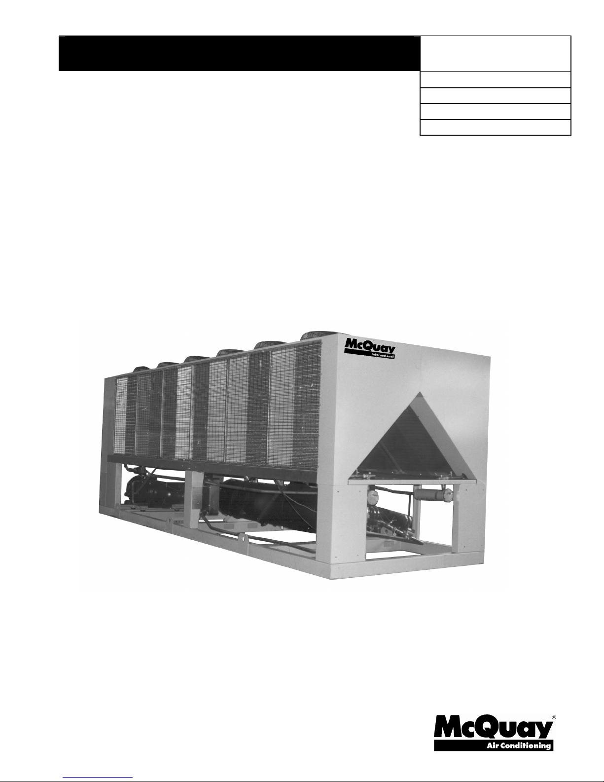
Air-Cooled Screw Compressor Chiller
AGS 120CS/H - AGS 210CS/H, Packaged
AGS 120CM/B – AHS 210CM/B, Remote Evaporator
60 Hertz, R-134a
Group: Chiller
Part Number: 331373301
Date: July 2008
Supersedes: March 2008
Page 2
Table of Contents
Introduction.............................................................3
General Description............................................3
Nomenclature.....................................................3
Inspection...........................................................3
Installation and Start-up ..........................................4
Handling.............................................................4
Location .............................................................5
Service Access...................................................5
Clearance Requirements....................................6
Restricted Airflow ...............................................7
Vibration Isolators.............................................13
Chilled Water Pump .........................................19
Water Piping ....................................................19
System Water Volume .....................................20
Variable Speed Pumping..................................20
Evaporator Freeze Protection...........................21
Operating Limits: ..............................................22
Flow Switch ......................................................22
Refrigerant Charge...........................................23
Glycol Solutions ...............................................23
Water Flow and Pressure Drop.............................24
Physical Data, Standard Efficiency .......................26
Physical Data, High Efficiency ..............................27
Dimensional Data .................................................29
Electrical Data ......................................................32
Field Wiring ......................................................32
Field Wiring Diagram ............................................42
BAS Interface ...................................................47
Remote Operator Interface Panel .....................47
Remote Evaporator...............................................48
Manufactured in an ISO Certified Facility
"McQuay" is a registered trademark of McQuay International
Information covers the McQuay International products at the time of publication and we reserve the right
The following are trademarks or registered trademarks of their respective companies: BACnet from ASHRAE; LONM
LONW
to make changes in design and construction at anytime without notice.
ORKS
from Echelon Corporation; GeneSys, McQuay and MicroTech II from McQuay International.
Solid State Starters .............................................. 63
Component Location ............................................ 70
System Maintenance ............................................ 74
Warranty Statement ............................................. 77
Service ................................................................. 77
2004 McQuay International
Piping Layout ................................................... 48
Field Wiring (Remote Evaporator) .................... 49
Kit Components ...............................................49
Refrigerant Line Sizing..................................... 49
Dimensions, Unit with Remote Evaporator ....... 51
Vibration Isolators, Remote Evaporator............58
Physical Data, Standard Efficiency...................60
Physical Data, High Efficiency.......................... 61
Major Component Location .............................. 70
Power Panel..................................................... 72
Control Panel ................................................... 73
General ............................................................ 74
Compressor Maintenance ................................ 74
Lubrication .......................................................74
Electrical Terminals.......................................... 75
Condensers...................................................... 75
Liquid Line Sight Glass .................................... 75
Lead-Lag.......................................................... 76
Preventative Maintenance Schedule ................76
Liquid Line Filter-Driers .................................... 77
Compressor Slide Valves ................................. 78
Electronic Expansion Valve (EXV).................... 78
Evaporator .......................................................79
Charging Refrigerant........................................ 79
Standard Controls ............................................80
Controls, Settings and Functions ..................... 82
Troubleshooting Chart......................................83
Periodic Maintenance Log................................84
Unit controllers are LONM
with an optional LONW
communications module
ARK
ARK and
certified
ORKS
2 IMM AGS-2
Page 3

Introduction
General Description
McQuay
refrigerating units that include the latest in engineered components arranged to provide a
compact and efficient unit. Each unit is completely assembled, factory wired, evacuated,
charged, tested and comes complete and ready for installation. Each unit consists of two
air-cooled condenser sections with integral subcooler sections, two semi-hermetic, singlescrew compressors with solid-state starters, a two-circuit shell-and-tube direct expansion
evaporator, and complete refrigerant piping. Each compressor has an independent
refrigeration circuit. Liquid line components included are manual liquid line shutoff valves,
charging ports, filter-driers, sight-glass/moisture indicators, solenoid valves and electronic
expansion valves. A discharge shutoff valve is included and a compressor suction shutoff
valve is optional. Other features include compressor heaters, evaporator heaters for freeze
protection, automatic one-time pumpdown of each refrigerant circuit upon circuit
shutdown, and an advanced fully integrated microprocessor control system.
AGS units are divided between standard efficiency (model numbers ending in “0”) and high
efficiency units (ending in “5”). The high efficiency units have certain larger components.
The units are optionally available with the evaporator shipped separately for remote
mounting indoors.
A high ambient option is required for operation in ambient temperatures above 115°F
(46°C), or 105°F (41°C) on units equipped with optional fan VFDs.
Information on the operation of the unit MicroTech II controller is in the OM AGS manual.
GeneSys
air-cooled water chillers are complete, self-contained automatic
Nomenclature
Rotary Screw Compressor
“0” Last Digit=Std. Efficiency
“5” Last Digit=High Efficiency
Air-Cooled
Global
Nominal Tons
A G S - XXX C S
S=Standard Ambient, Packaged Unit
M=Standard Ambient, Remote Evaporator
H=Packaged with High Ambient Option
B=Remote with High Ambient Option.
Design Vintage
Inspection
When the equipment is received, carefully check all items against the bill of lading to check
for a complete shipment. Check all units for damage upon arrival. All shipping damage
must be reported to the carrier and a claim must be filed with the carrier. Check the unit’s
serial plate before unloading the unit to be sure that it agrees with the power supply
available. Physical damage to unit after acceptance is not the responsibility of McQuay
International.
Note: Unit shipping and operating weights are shown in the Physical Data Tables on page
26 for packaged units and page 60 for remote evaporator models.
IMM AGS-2 3
Page 4
Installation and Start-up
Sharp edges and coil surfaces are a potential injury hazard. Avoid contact with them.
Note: Installation and maintenance are to be performed only by qualified personnel who are
familiar with local codes and regulations, and experienced with this type of equipment.
Start-up by McQuayService is included on all units sold for installation within the USA and
Canada and must be performed by them to initiate the standard limited product warranty.
Two-week prior notification of start-up is required. The contractor should obtain a copy of
the Start-up Scheduled Request Form from the sales representative or from the nearest
office of McQuayService.
Escaping refrigerant can displace air and cause suffocation. Immediately evacuate
and ventilate the equipment area. If the unit is damaged, follow Environmental
Protection Agency (EPA) requirements. Do not expose sparks, arcing equipment, open
flame or other ignition source to the refrigerant.
Handling
Avoid rough handling shock due to impact or dropping the unit. Do not push or pull the
unit.
WARNING
WARNING
Never allow any part of the unit to fall during unloading or moving, as this can result in
serious damage.
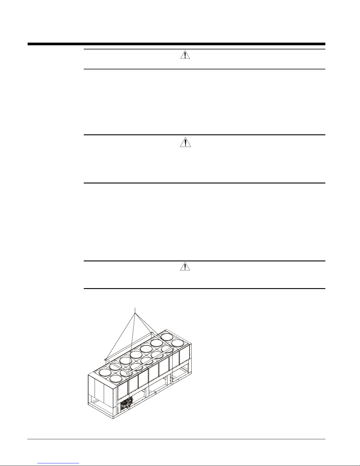
To lift the unit, lifting tabs with 2½" (64 mm) diameter holes are provided on the base of the
unit. All lifting holes must be used when lifting the unit. Spreader bars and cables should
be arranged to prevent damage to the condenser coils or unit cabinet (see Figure 1).
DANGER
Improper lifting or moving unit can result in property damage, severe
personal injury or death. Follow rigging and moving instructions carefully.
Figure 1, Required Lifting Method
NOTES:
1. All rigging points on a unit must be
used. See location and weights at
lifting points beginning on page 13 for a
specific size unit.
2. Crosswise and lengthwise spreader
bars must be used to avoid damage to
unit. Lifting cables from the unit
mounting holes up must be vertical.
3. The number of condenser sections, and
fans can vary from this diagram.
4 IMM AGS-2
Page 5
Location
Locate the unit carefully to provide proper airflow to the condenser. (See Figure 2 on page
6 for required clearances).
Due to the shape of the condenser coils on the AGS chillers, it is recommended that the unit
be oriented so that prevailing winds blow parallel to the unit length, thus minimizing the
wind effect on condensing pressure and performance. If low ambient temperature operation
is expected, optional louvers should be installed if the unit has no protection against
prevailing winds.
Using less clearance than shown in Figure 2 can cause discharge air recirculation to the
condenser and could have a significant detrimental effect on unit performance.
See Restricted Airflow beginning on page 7 for further information.
For pad-mounted units, it is recommended that the unit be raised a few inches with suitable
supports, located at least under the mounting locations, to allow water to drain from under
the unit and to facilitate cleaning under it
Service Access
Compressors, filter-driers, and manual liquid line shutoff valves are accessible on each side
or end of the unit. The evaporator heater is located on the barrel.
The control panels are located on the end of the chiller. The left-hand control box contains
the unit and circuit microprocessors as well as transformers, fuses and terminal. The righthand panel contains a circuit breaker and solid state starter for each compressor plus fuses,
fan VFD (optional) and fan contactors. A minimum of four feet of clearance is required in
front of the panels.
The side clearance required for airflow provides sufficient service clearance.
On all AGS units, the condenser fans and motors can be removed from the top of the unit.
The complete fan/motor assembly can be removed for service. The fan blade must be
removed for access to wiring terminals at the top of the motor.
WARNING
Disconnect, lockout and tag all power to the unit before servicing condenser fan
motors or compressors.
Failure to do so can cause bodily injury or death.
Do not block access to the sides or ends of the unit with piping or conduit. These areas
must be open for service access. Do not block any access to the control panels with a fieldmounted disconnect switches.
IMM AGS-2 5
Page 6
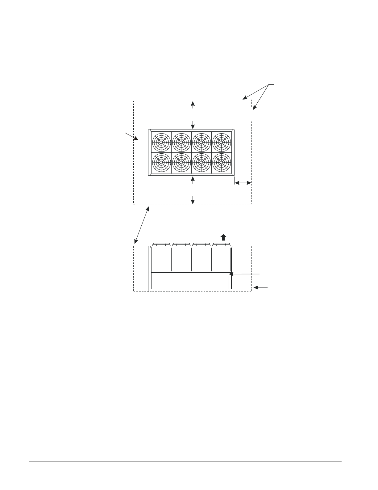
Clearance Requirements
5ft (1.5m)
5ft (1.5m)
3ft (1m) for service
Air Flo
w
No obstructions allowed
above unit at any heigh
t
See notes 2 & 4
concerning wall
height at unit sides.
6ft (1.8m)
6ft (1.8m)
Figure 2, Clearance Requirements, AGS 120C – AGS 210C
if open fence or 50% open wall
if solid wall (see note 3 for pit)
4ft (1.2m)
For electric
panel access
if open fence or 50% open wall
if solid wall (see note 3 for pit)
No obstructions.
Recommended area
required for unit
operation, air flow
and maintenance
access.
See Note 5
Wall or
Fence
Notes:
1. Minimum side clearance between two units is 12 feet (3.7 meters).
2. Unit must not be installed in a pit or enclosure that is deeper or taller than the height of the unit
unless extra clearance is provided per note 4.
3. Minimum clearance on each side is 8 feet (2.4 meters) when installed in a pit no deeper than the
unit height.
4. Minimum side clearance to a side wall or building taller than the unit height is 6 feet (1.8 meters),
provided no solid wall above 6 feet (1.8 meters) is closer than 12 feet (3.7 meters) to the opposite
side of the unit.
5. Do not mount electrical conduits where they can block service access to compressor controls,
refrigerant driers or valves.
6. There must be no obstruction of the fan discharge.
7. Field installed switches must not interfere with service access or airflow.
8. The evaporator can be removed from the side of the unit and may require the temporary removal
of a coil section support post. See dimension drawings beginning on page 29 for details.
9. If the airflow clearances cannot be met, see the following pages on Restricted Airflow.
6 IMM AGS-2
Page 7
Restricted Airflow
General
The clearances required for design operation of AGS air-cooled condensers are described in
the previous section. Occasionally, these clearances cannot be maintained due to site
restrictions such as units being too close together or a fence or wall restricting airflow, or
both.
The McQuay AGS chillers have several features that can mitigate the problems attributable
to restricted airflow.
• The shape of the condenser section allows inlet air for these coils to come in from both
sides and the bottom. All the coils on one side serve one compressor. Every
compressor always has its own independent refrigerant circuit.
• The MicroTech II control is proactive in response to off-design conditions. In the
case of single or compounded influences restricting airflow to the unit, the
microprocessor will act to keep the compressor(s) running (at reduced capacity) as long
as possible, rather than allowing a shut-off on high discharge pressure.
Figure 3, Coil and Fan Arrangement
The following sections discuss the most common situations of condenser air restriction and
give capacity and power adjustment factors for each. Note that in unusually severe
conditions, the MicroTech II controller will adjust the unit operation to remain online until
a less severe condition is reached.
IMM AGS-2 7
Page 8
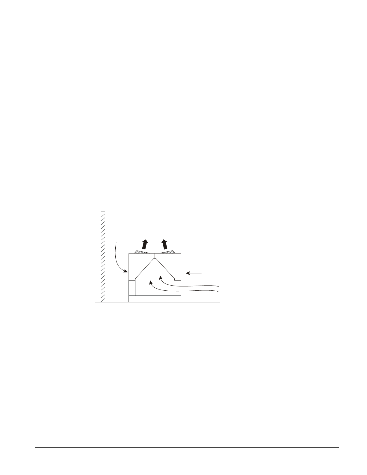
Case 1, Building or Wall on One Side of One Unit
5 ft.
(1.5m)
(1.8m)
The existence of a screening wall, or the wall of a building, in close proximity to an aircooled chiller is common in both rooftop and ground level applications. Hot air
recirculation on the coils adjoining the wall will increase compressor discharge pressure,
decreasing capacity and increasing power consumption.
When close to a wall, it is desirable to place chillers on the north or east side of them. It is
also desirable to have prevailing winds blowing parallel to the unit’s long axis. The worst
case is to have wind blowing hot discharge air into the wall.
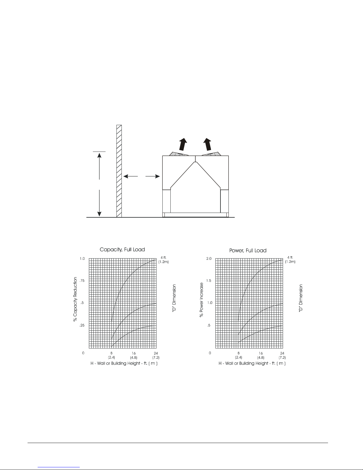
Figure 4, Unit Adjacent to Wall
D
H
Figure 5, Adjustment Factors
(1.5m)
6 ft.
(1.8m)
5 ft.
6 ft.
8 IMM AGS-2
Page 9
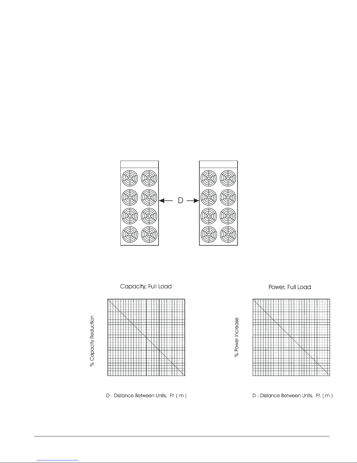
Case 2, Two Units Side By Side
Two or more units sited side by side are common. If spaced closer than 12 feet (3.7 meters), or 8
feet (2.5 meters), depending on size, it is necessary to adjust the performance of each unit.
Circuits adjoining each other are affected. NOTE: This case applies only to two units side by side.
See Case 3 for three or more parallel units. If one of the two units also has a wall adjoining it, see
Case 1. Add the two adjustment factors together and apply to the unit located between the wall
and the other unit.
Mounting units end to end will not necessitate adjusting performance. Depending on the actual
arrangement, sufficient space must be left between the units for access to the control panel door
opening and/or evaporator tube removal. See “Clearance” section of this guide for requirements
for specific units.
Figure 6, Two Units Side by Side
Figure 7, Adjustment Factor
3.0
2.0
1.0
0
9
(2.7)
10
(3.0)
11
(3.3)
12
(3.6)
6.0
4.0
2.0
0
9
(2.7)
10
(3.0)
11
(3.3)
12
(3.6)
IMM AGS-2 9
Page 10
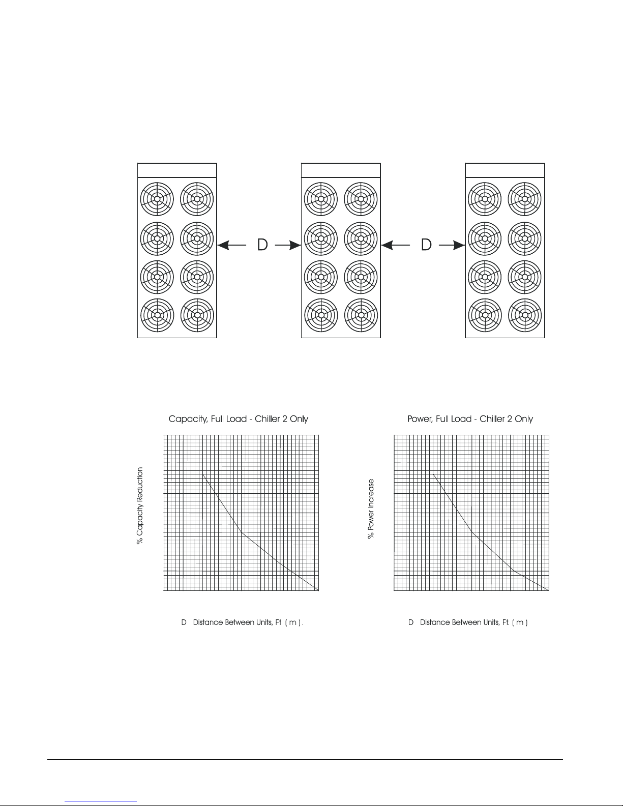
Case 3, Three or More Units Side By Side
When three or more units are side by side, the outside units (chillers 1 and 3 in this case) are
influenced by the middle unit only on their inside circuits. Their adjustment factors will be the
same as Case 2. All inside units (only chiller 2 in this case) are influenced on both sides and must
be adjusted by the factors shown below.
Figure 8, Three or More Units
Chiller 1 Chiller 2 Chiller 3
Figure 9, Adjustment Factor
4.0
3.0
2.0
1.0
0
15
(4.6)
16
(4.9)
17
(5.2)
18
(5.5)
8.0
6.0
4.0
2.0
0
15
(4.6)
16
(4.9)
17
(5.2)
18
(5.5)
10 IMM AGS-2
Page 11
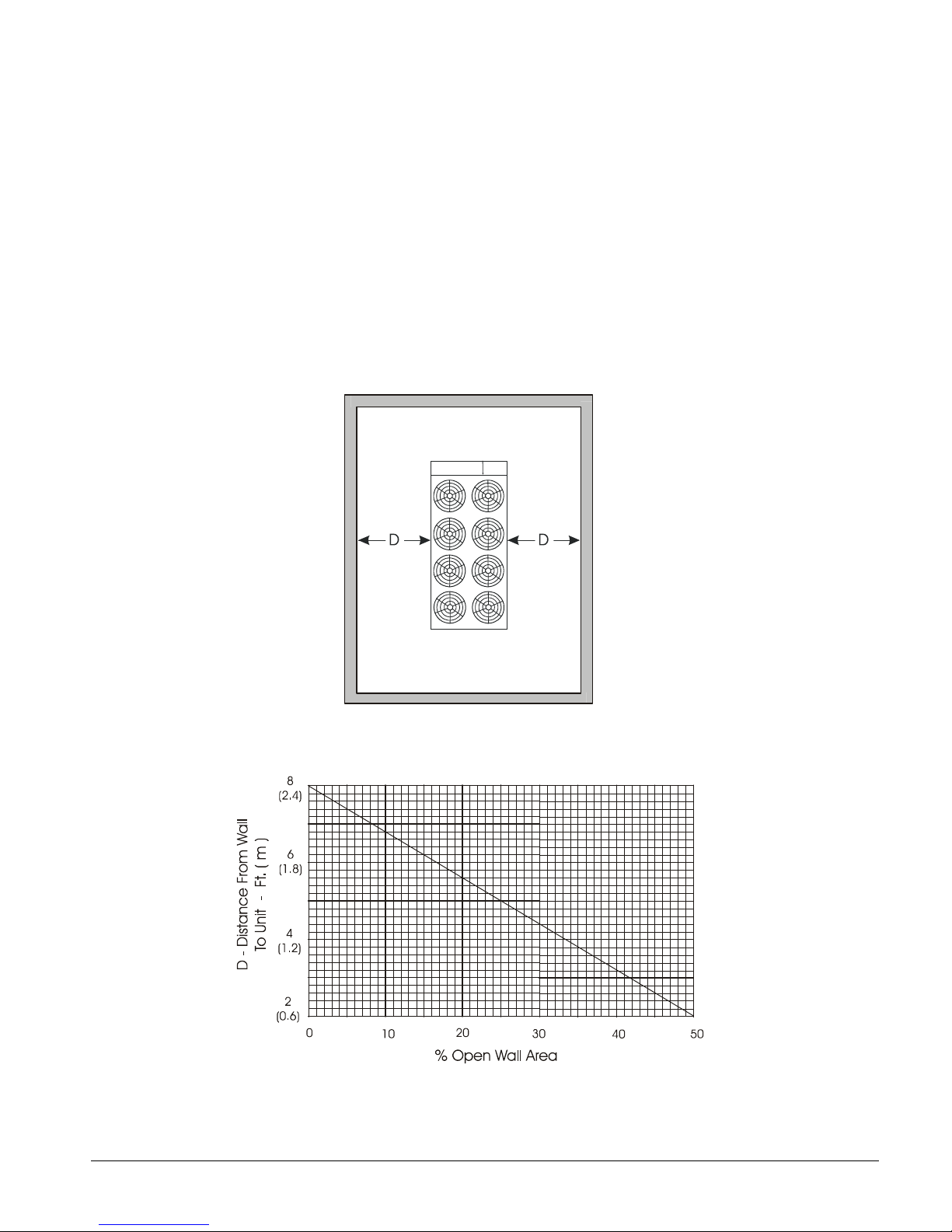
Case 4, Open Screening Walls
Decorative screening walls are often used to help conceal a unit either on grade or on a rooftop.
These walls should be designed such that the combination of their open area and distance from the
unit do not require performance adjustment. It is assumed that the wall height is equal to or less
than the unit height when mounted on its base support. This is usually satisfactory for concealment.
If the wall height is greater than the unit height, see Case 5, Pit Installation.
The distance from the ends of the unit to the end walls must be sufficient for service, opening
control panel doors, and pulling evaporator tubes, as applicable.
If each side wall is a different distance from the unit, the distances can be averaged, providing either
wall is not less than 8 feet (2.4 meters) from the unit. For example, do not average 4 feet and 20
feet to equal 12 feet.
Figure 10, Open Screening Walls
Figure 11, Wall Free Area vs. Distance
IMM AGS-2 11
Page 12

Case 5, Pit/Solid Wall Installation
Pit installations can cause operating problems and great care must be exercised if they are
to be used on an installation. Recirculation and restriction can both occur. A solid wall
surrounding a unit is substantially the same as a pit and the data presented in this case
should be used.
Steel grating is sometimes used to cover a pit to prevent accidental falls or trips into the pit.
The grating material and installation design must be strong enough to prevent such
accidents, yet provide abundant open area or serious recirculation problems will occur.
Have any pit installation reviewed by the McQuay sales office prior to installation to
discuss whether it has sufficient airflow characteristics. The installation design engineer
must approve the work and is responsible for design criteria.
Figure 12, Pit Installation
Figure 13, Adjustment Factor
12 IMM AGS-2
Page 13
Vibration Isolators
“G”
“E”
“F”
“D”
“C”
“A”
“B”
COG
44.00
“CC”
MM
Vibration isolators are recommended for all roof-mounted installations or wherever vibration
transmission is a consideration. Initially installed the unit on shims or blocks at the illustrated "free
height" of the isolator that is six inches for the McQuay isolators shown. When all piping, wiring,
flushing, charging, etc. is complete, adjust the springs upward to load them and to provide clearance
to free the blocks, which are then removed.
Installation of spring isolators requires flexible pipe connections and at least three feet of conduit
flex tie-ins. Support piping and conduit independently from the unit to not stress connections.
There are separate weight and isolator tables for copper fin coils. All other coil types, such as
ElectroFin and Blackfin, use the aluminum fin data.
Isolator bolting: the unit base is an enclosed box design and may have six or ten mounting
locations, depending on the date of manufacture. Mounting locations M1 and M2 at dimension “C”
and locations M5 and M6 at dimension “E” are not used. Locations MM1, MM2, M3, M4, MM5
and MM6 have access holes on top of the base, above the lower mounting holes and should be used
for all isolator types. One simple method of bolting the base to the isolators (if required) is to
remove the short threaded studs, usually provided with isolators, and replace them with eight-inch
threaded rod. The rod will extend above the top of the base and a washer and nut can then be easily
attached.
Figure 14, Mounting and Lifting Dimensions
M6
M5
MM5
L3
L4
“EE”
M4
M3
MM2MM6
L2
L1
M2
1
M1
X
O
B
L
O
R
T
N
O
C
330712801D0400_R0A
NOTE: Dimensions are on the following page.
IMM AGS-2 13
Page 14
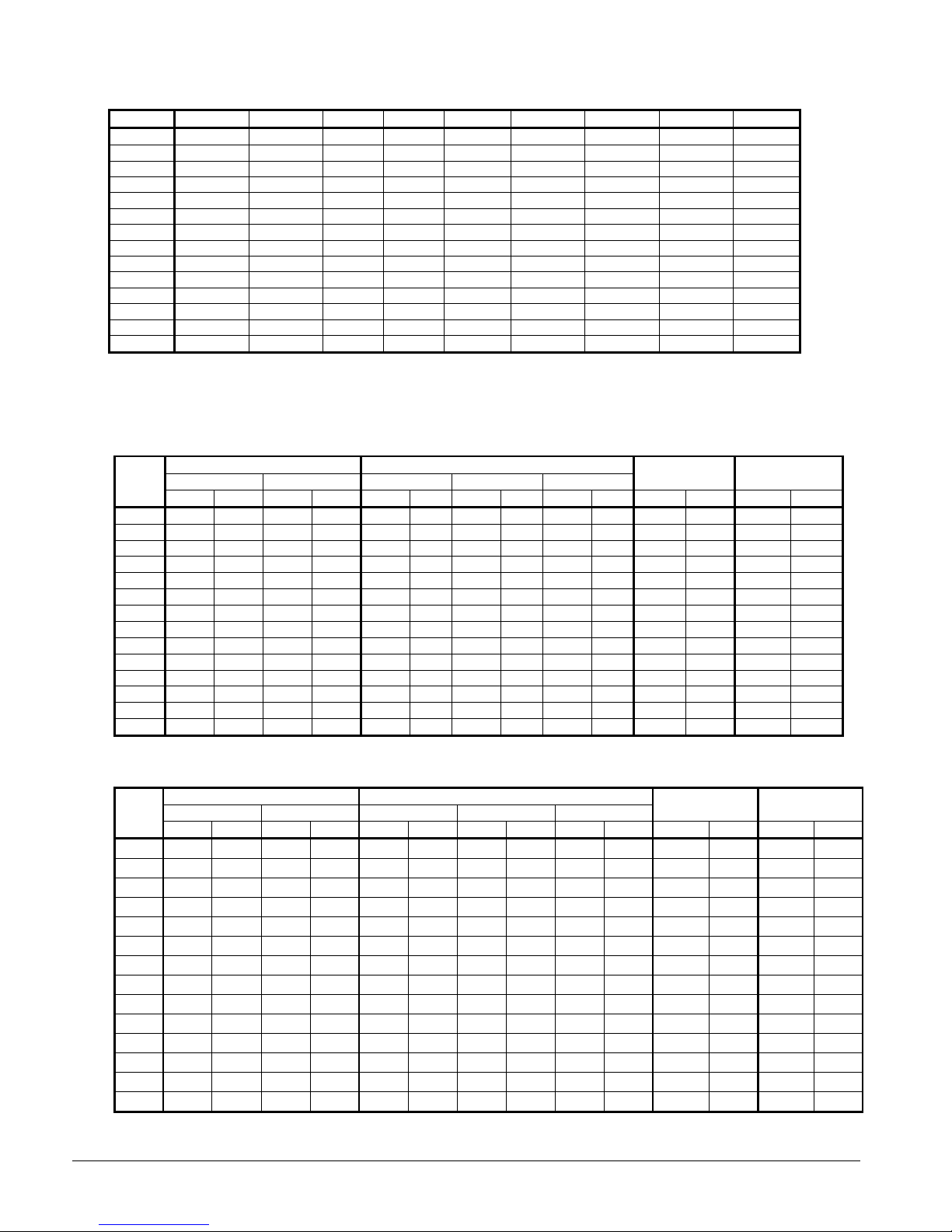
Table 1, Dimensions
MODEL A B C CC D E EE F G
120 36.00 136.60 12.00 21.00 57.30 174.60 165.60 71.49 186.60
125 36.00 168.85 12.00 21.00 69.25 212.80 203.80 86.54 224.80
130 36.00 136.60 12.00 21.00 57.30 174.60 165.60 71.49 186.60
135 36.00 168.85 12.00 21.00 69.25 212.80 203.80 86.54 224.80
140 36.00 136.60 12.00 21.00 57.30 174.60 165.80 71.49 186.60
145 36.00 168.85 12.00 21.00 69.25 212.80 203.80 86.66 224.80
160 36.00 136.60 12.00 21.00 57.30 174.60 165.60 74.37 186.60
165 36.00 189.00 12.00 21.00 84.00 251.00 242.00 105.17 263.00
170 36.00 168.85 12.00 21.00 69.25 212.80 203.80 89.65 224.80
175 36.00 189.00 12.00 21.00 84.00 251.00 242.00 105.17 263.00
180 36.00 168.85 12.00 21.00 69.25 212.80 203.80 89.65 224.80
190 36.00 168.85 12.00 21.00 69.25 212.80 203.80 89.65 224.80
195 36.00 189.00 12.00 21.00 84.00 251.00 242.00 105.17 263.00
210 36.00 189.00 12.00 21.00 84.00 251.00 242.00 105.17 263.00
NOTES:
1. Use location “C”, not “CC”, for mounting.
2. Center of gravity (F) is calculated from shipping weight
3. Dimensions are in inches.
4. Mounting holes are 0.75 inch diameter and have center located 2.0 inches from the outside edge.
Table 2, Lifting and Mounting Weights, Packaged, Aluminum Fins, AGS-CS/H
AGS
120 2919 1324 1591 722 1749 793 1645 746 1333 605 9452 4287 9020 4091
125 3161 1434 1941 880 1996 905 1887 856 1583 718 10930 4958 10205 4629
130 2919 1324 1591 722 1749 793 1645 746 1333 605 9452 4287 9020 4091
135 3161 1434 1941 880 1996 905 1887 856 1583 718 10930 4958 10205 4629
140 2919 1324 1591 722 1749 793 1645 746 1333 605 9452 4287 9020 4091
145 3075 1395 1896 860 1916 869 1810 821 1517 688 10485 4756 9942 4510
160 2933 1330 1809 821 1802 817 1742 790 1561 708 10209 4631 9484 4302
165 3017 1369 2489 1129 2137 969 2038 924 1789 811 11928 5411 11011 4995
170 3269 1483 2007 910 1945 882 1904 864 1790 812 11277 5115 10552 4786
175 3017 1369 2489 1129 2137 969 2038 924 1789 811 11928 5411 11011 4995
180 3269 1483 2007 910 1945 882 1904 864 1790 812 11277 5115 10552 4786
190 3269 1483 2007 910 1945 882 1904 864 1790 812 11277 5115 10552 4786
195 3017 1369 2489 1129 2137 969 2038 924 1789 811 11928 5411 11011 4995
210 3017 1369 2489 1129 2137 969 2038 924 1789 811 11928 5411 11011 4995
Lifting Weights Mounting Weights
L1, L2 L3, L4 MM1, MM2 M3, M4 MM5, MM6
lbs kg lbs kg lbs kg lbs kg lbs kg lbs kg lbs kg
Operating
Weight
Shipping
Weight
Table 3, Lifting and Mounting Weights, Packaged Copper Fins, AGS-CS/H
AGS
120
125
130
135
140
145
160
165
170
175
180
190
195
210
Lifting Weights Mounting Weights
L1, L2 L3, L4 MM1, MM2 M3, M4 MM5, MM6
lbs kg lbs kg lbs kg lbs kg lbs kg lbs kg lbs kg
3557 1613 2229 1011 2174 986 2070 939 1758 798 10728 4866 10296 4670
3959 1796 2739 1242 2528 1147 2419 1097 2115 959 12526 5682 11801 5353
3557 1613 2229 1011 2174 986 2070 939 1758 798 10728 4866 10296 4670
3959 1796 2739 1242 2528 1147 2419 1097 2115 959 12526 5682 11801 5353
3557 1613 2229 1011 2174 986 2070 939 1758 798 10728 4866 10296 4670
3873 1757 2694 1222 2448 1110 2342 1062 2049 929 12081 5480 11538 5234
3571 1620 2447 1110 2227 1010 2167 983 1986 901 11485 5210 10760 4881
3975 1803 3447 1564 2776 1259 2677 1214 2428 1101 13844 6280 12927 5864
4067 1845 2805 1272 2477 1124 2436 1105 2322 1053 12873 5839 12148 5510
3975 1803 3447 1564 2776 1259 2677 1214 2428 1101 13844 6280 12927 5864
4067 1845 2805 1272 2477 1124 2436 1105 2322 1053 12873 5839 12148 5510
4067 1845 2805 1272 2477 1124 2436 1105 2322 1053 12873 5839 12148 5510
3975 1803 3447 1564 2776 1259 2677 1214 2428 1101 13844 6280 12927 5864
3975 1803 3447 1564 2776 1259 2677 1214 2428 1101 13844 6280 12927 5864
Operating
Weight
Shipping
Weight
14 IMM AGS-2
Page 15
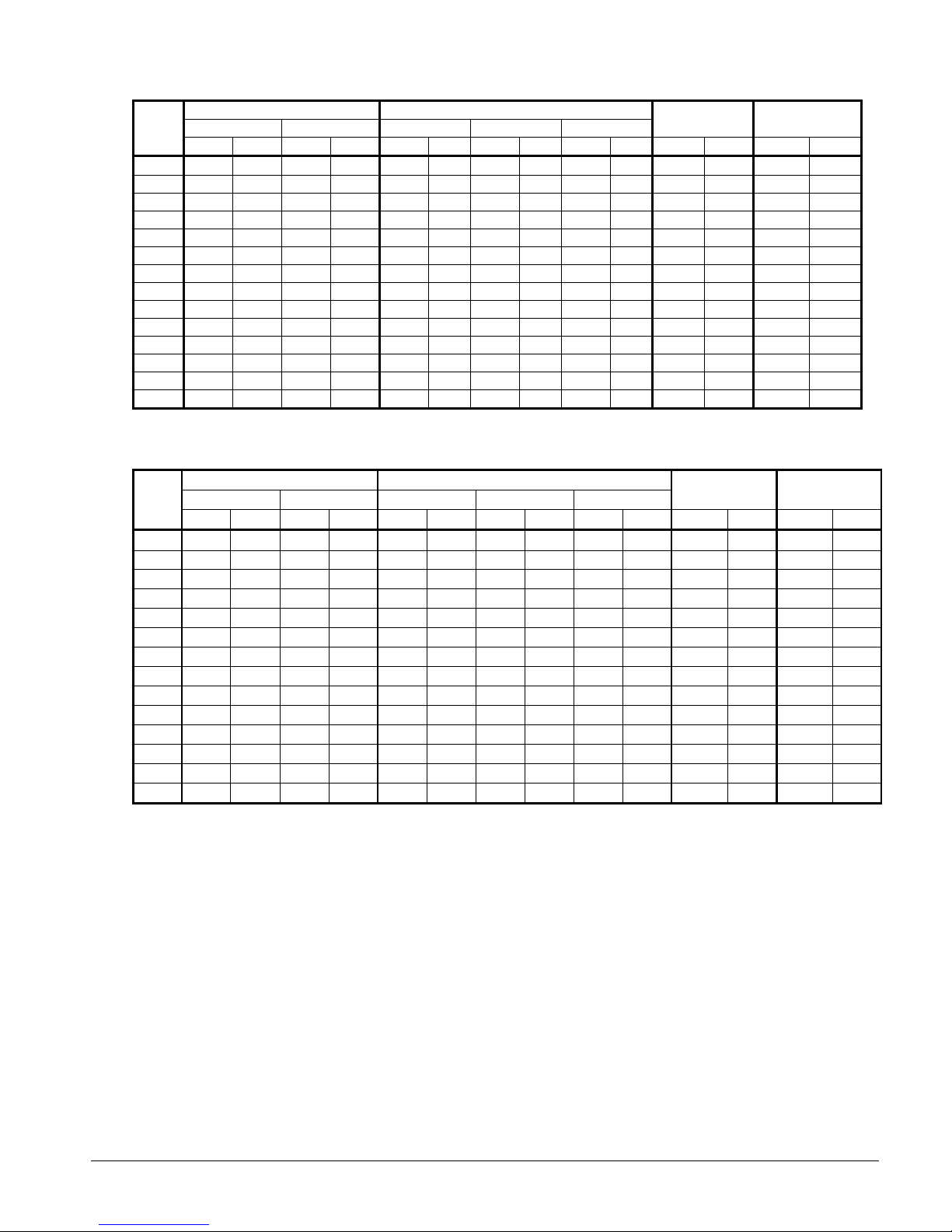
Table 4, Lifting & Mounting Weights, Remote Evaporator, Aluminum Fins, AGS-CM/B
AGS
120
125
130
135
140
145
160
165
170
175
180
190
195
210
Lifting Weights Mounting Weights
L1, L2 L3, L4 MM1, MM2 M3, M4 MM5, MM6
lbs kg lbs kg lbs kg lbs kg lbs kg lbs kg lbs kg
3029 1374 1021 463 1780 807 1521 690 749 340 8100 3674 8100 3674
3169 1437 1307 593 1938 879 1659 753 879 399 8952 4061 8952 4061
3029 1374 1021 463 1780 807 1521 690 749 340 8100 3674 8100 3674
3169 1437 1307 593 1938 879 1659 753 879 399 8952 4061 8952 4061
3029 1374 1021 463 1780 807 1521 690 749 340 8100 3674 8100 3674
3169 1437 1307 593 1938 879 1659 753 879 399 8952 4061 8952 4061
3029 1374 1021 463 1780 807 1521 690 749 340 8100 3674 8100 3674
3196 1450 1590 721 2099 952 1764 800 923 419 9571 4341 9571 4341
3169 1437 1307 593 1938 879 1659 753 879 399 8952 4061 8952 4061
3196 1450 1590 721 2099 952 1764 800 923 419 9571 4341 9571 4341
3169 1437 1307 593 1938 879 1659 753 879 399 8952 4061 8952 4061
3169 1437 1307 593 1938 879 1659 753 879 399 8952 4061 8952 4061
3196 1450 1590 721 2099 952 1764 800 923 419 9571 4341 9571 4341
3196 1450 1590 721 2099 952 1764 800 923 419 9571 4341 9571 4341
Operating
Weight
Shipping
Weight
Table 5, Lifting & Mounting Weights, Remote Evaporator, Copper Fins, AGS-CM/B
AGS
120
125
130
135
140
145
160
165
170
175
180
190
195
210
Lifting Weights Mounting Weights
L1, L2 L3, L4 MM1, MM2 M3, M4 MM5, MM6
lbs kg lbs kg lbs kg lbs kg lbs kg lbs kg lbs kg
3667 1663 1659 753 2205 1000 1946 883 1174 533 9376 4253 9376 4253
3967 1799 2105 955 2470 1120 2191 994 1411 640 10548 4785 10548 4785
3667 1663 1659 753 2205 1000 1946 883 1174 533 9376 4253 9376 4253
3967 1799 2105 955 2470 1120 2191 994 1411 640 10548 4785 10548 4785
3667 1663 1659 753 2205 1000 1946 883 1174 533 9376 4253 9376 4253
3967 1799 2105 955 2470 1120 2191 994 1411 640 10548 4785 10548 4785
3667 1663 1659 753 2205 1000 1946 883 1174 533 9376 4253 9376 4253
4154 1884 2548 1156 2738 1242 2403 1090 1562 708 11487 5211 11487 5211
3967 1799 2105 955 2470 1120 2191 994 1411 640 10548 4785 10548 4785
4154 1884 2548 1156 2738 1242 2403 1090 1562 708 11487 5211 11487 5211
3967 1799 2105 955 2470 1120 2191 994 1411 640 10548 4785 10548 4785
3967 1799 2105 955 2470 1120 2191 994 1411 640 10548 4785 10548 4785
4154 1884 2548 1156 2738 1242 2403 1090 1562 708 11487 5211 11487 5211
4154 1884 2548 1156 2738 1242 2403 1090 1562 708 11487 5211 11487 5211
Operating
Weight
Shipping
Weight
IMM AGS-2 15
Page 16
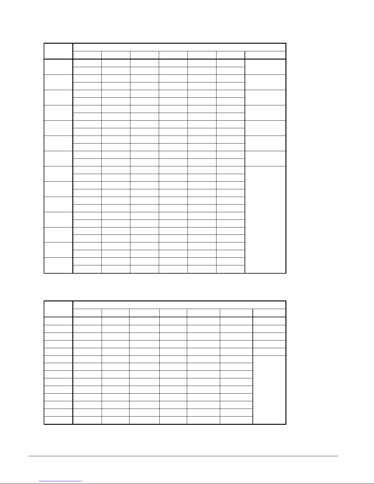
Table 6, Spring Vibration Isolators, Aluminum Fin, AGS-CS/H
AGS
Model
120
125
130
135
140
145
160
165
170
175
180
190
195
210
M1 M2 M3 M4 M5 M6 Kit Number
CP2-28 CP2-28 CP2-28 CP2-28 CP2-27 CP2-27
GREEN GREEN GREEN GREEN ORANGE ORANGE
CP2-31 CP2-31 CP2-31 CP2-31 CP2-28 CP2-28
GRAY GRAY GRAY GRAY GREEN GREEN
CP2-28 CP2-28 CP2-28 CP2-28 CP2-27 CP2-27
GREEN GREEN GREEN GREEN ORANGE ORANGE
CP2-31 CP2-31 CP2-31 CP2-31 CP2-28 CP2-28
GRAY GRAY GRAY GRAY GREEN GREEN
CP2-28 CP2-28 CP2-28 CP2-28 CP2-27 CP2-27
GREEN GREEN GREEN GREEN ORANGE ORANGE
CP2-31 CP2-31 CP2-31 CP2-31 CP2-28 CP2-28
GRAY GRAY GRAY GRAY GREEN GREEN
CP2-28 CP2-28 CP2-28 CP2-28 CP2-28 CP2-28
GREEN GREEN GREEN GREEN GREEN GREEN
CP2-31 CP2-31 CP2-31 CP2-31 CP2-31 CP2-31
GRAY GRAY GRAY GRAY GRAY GRAY
CP2-31 CP2-31 CP2-31 CP2-31 CP2-31 CP2-31
GRAY GRAY GRAY GRAY GRAY GRAY
CP2-31 CP2-31 CP2-31 CP2-31 CP2-31 CP2-31
GRAY GRAY GRAY GRAY GRAY GRAY
CP2-31 CP2-31 CP2-31 CP2-31 CP2-31 CP2-31
GRAY GRAY GRAY GRAY GRAY GRAY
CP2-31 CP2-31 CP2-31 CP2-31 CP2-31 CP2-31
GRAY GRAY GRAY GRAY GRAY GRAY
CP2-31 CP2-31 CP2-31 CP2-31 CP2-31 CP2-31
GRAY GRAY GRAY GRAY GRAY GRAY
CP2-31 CP2-31 CP2-31 CP2-31 CP2-31 CP2-31
GRAY GRAY GRAY GRAY GRAY GRAY
Mounting Location
330904101
330904102
330904101
330904102
330904101
330904102
330904103
330904104
Table 7, Neoprene-in-Shear Isolators, Aluminum Fin, AGS-CS/H
AGS
Model
120
125
130
135
140
145
160
165
170
175
180
190
195
210
M1 M2 M3 M4 M5 M6 Kit Number
RP-4, RED RP-4, RED RP-4, RED RP-4, RED RP-4, BLACK RP-4, BLACK 330904111
RP-4, RED RP-4, RED RP-4, RED RP-4, RED RP-4, RED RP-4, RED 330904112
RP-4, RED RP-4, RED RP-4, RED RP-4, RED RP-4, BLACK RP-4, BLACK 330904111
RP-4, RED RP-4, RED RP-4, RED RP-4, RED RP-4, RED RP-4, RED 330904112
RP-4, RED RP-4, RED RP-4, RED RP-4, RED RP-4, BLACK RP-4, BLACK 330904111
RP-4, RED RP-4, RED RP-4, RED RP-4, RED RP-4, RED RP-4, RED
RP-4, RED RP-4, RED RP-4, RED RP-4, RED RP-4, RED RP-4, RED
RP-4, RED RP-4, RED RP-4, RED RP-4, RED RP-4, RED RP-4, RED
RP-4, RED RP-4, RED RP-4, RED RP-4, RED RP-4, RED RP-4, RED
RP-4, RED RP-4, RED RP-4, RED RP-4, RED RP-4, RED RP-4, RED
RP-4, RED RP-4, RED RP-4, RED RP-4, RED RP-4, RED RP-4, RED
RP-4, RED RP-4, RED RP-4, RED RP-4, RED RP-4, RED RP-4, RED
RP-4, RED RP-4, RED RP-4, RED RP-4, RED RP-4, RED RP-4, RED
RP-4, RED RP-4, RED RP-4, RED RP-4, RED RP-4, RED RP-4, RED
Mounti ng Location ( See Footprint D ra wings, page 13)
330904112
16 IMM AGS-2
Page 17
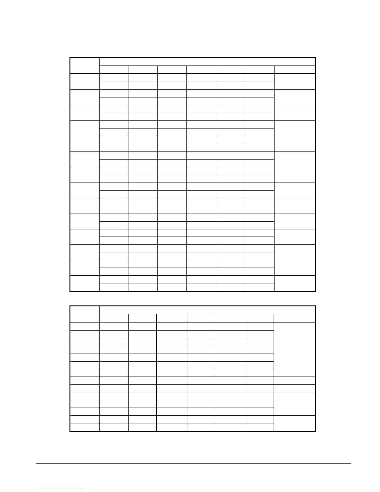
Table 8, Spring Vibration Isolators, Copper Fin, AGS-CS/H
AGS
Model
120
125
130
135
140
145
160
165
170
175
180
190
195
210
M1 M2 M3 M4 M5 M6 Kit Number
CP2-31 CP2-31 CP2-31 CP2-31 CP2-28 CP2-28
GRAY GRAY GRAY GRAY GREEN GREEN
CP2-32 CP2-32 CP2-31 CP2-31 CP2-31 CP2-31
WHITE WHITE GRAY GRAY GRAY GRAY
CP2-31 CP2-31 CP2-31 CP2-31 CP2-28 CP2-28
GRAY GRAY GRAY GRAY GREEN GREEN
CP2-32 CP2-32 CP2-31 CP2-31 CP2-31 CP2-31
WHITE WHITE GRAY GRAY GRAY GRAY
CP2-31 CP2-31 CP2-31 CP2-31 CP2-28 CP2-28
GRAY GRAY GRAY GRAY GREEN GREEN
CP2-31 CP2-31 CP2-31 CP2-31 CP2-31 CP2-31
GRAY GRAY GRAY GRAY GRAY GRAY
CP2-31 CP2-31 CP2-31 CP2-31 CP2-31 CP2-31
GRAY GRAY GRAY GRAY GRAY GRAY
CP2-32 CP2-32 CP2-32 CP2-32 CP2-31 CP2-31
WHITE WHITE WHITE WHITE GRAY GRAY
CP2-32 CP2-32 CP2-31 CP2-31 CP2-31 CP2-31
WHITE WHITE GRAY GRAY GRAY GRAY
CP2-32 CP2-32 CP2-32 CP2-32 CP2-31 CP2-31
WHITE WHITE WHITE WHITE GRAY GRAY
CP2-32 CP2-32 CP2-31 CP2-31 CP2-31 CP2-31
WHITE WHITE GRAY GRAY GRAY GRAY
CP2-32 CP2-32 CP2-31 CP2-31 CP2-31 CP2-31
WHITE WHITE GRAY GRAY GRAY GRAY
CP2-32 CP2-32 CP2-32 CP2-32 CP2-31 CP2-31
WHITE WHITE WHITE WHITE GRAY GRAY
CP2-32 CP2-32 CP2-32 CP2-32 CP2-31 CP2-31
WHITE WHITE WHITE WHITE GRAY GRAY
Mounting Location
330904102
330904105
330904102
330904105
330904102
330904104
330904104
330904106
330904105
330904106
330904105
330904105
330904106
330904106
Table 9, Neoprene-in-Shear Isolators, Copper Fin, AGS-CS/H
AGS
Model
120
125
130
135
140
145
160
165
170
175
180
190
195
210
M1 M2 M3 M4 M5 M6 Kit Number
RP-4, RED RP-4, RED RP-4, RED RP-4, RED RP-4, RED RP-4, RED
RP-4, RED RP-4, RED RP-4, RED RP-4, RED RP-4, RED RP-4, RED
RP-4, RED RP-4, RED RP-4, RED RP-4, RED RP-4, RED RP-4, RED
RP-4, RED RP-4, RED RP-4, RED RP-4, RED RP-4, RED RP-4, RED
RP-4, RED RP-4, RED RP-4, RED RP-4, RED RP-4, RED RP-4, RED
RP-4, RED RP-4, RED RP-4, RED RP-4, RED RP-4, RED RP-4, RED
RP-4, RED RP-4, RED RP-4, RED RP-4, RED RP-4, RED RP-4, RED
RP-4, GRN RP-4, GRN RP-4, GRN RP-4, GRN RP-4, RED RP-4, RED 330904113
RP-4, RED RP-4, RED RP-4, RED RP-4, RED RP-4, RED RP-4, RED 330904112
RP-4, GRN RP-4, GRN RP-4, GRN RP-4, GRN RP-4, RED RP-4, RED 330904113
RP-4, RED RP-4, RED RP-4, RED RP-4, RED RP-4, RED RP-4, RED
RP-4, RED RP-4, RED RP-4, RED RP-4, RED RP-4, RED RP-4, RED
RP-4, GRN RP-4, GRN RP-4, GRN RP-4, GRN RP-4, RED RP-4, RED
RP-4, GRN RP-4, GRN RP-4, GRN RP-4, GRN RP-4, RED RP-4, RED
IMM AGS-2 17
Mounti ng Location ( See Footprint D ra wing, pg. 13)
330904112
330904112
330904113
Page 18
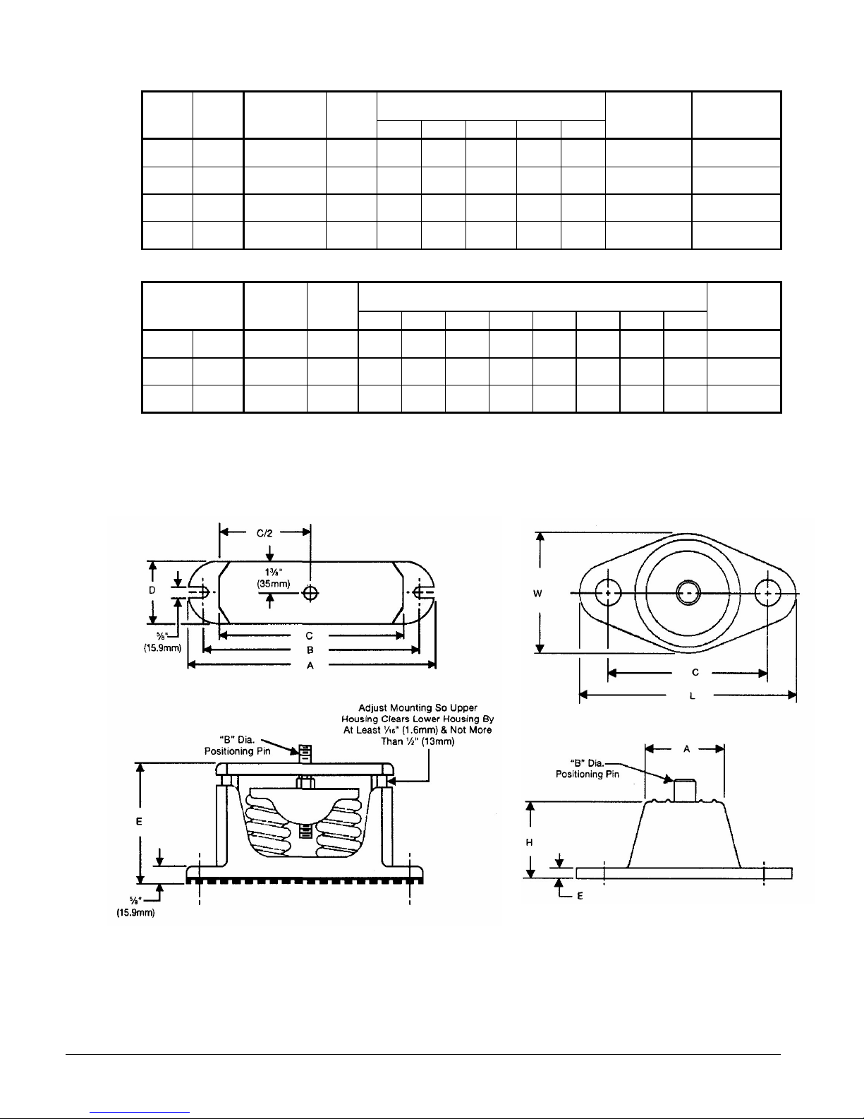
Table 10, Spring Flex Isolators
9.0
(228.6)
9.0
(228.6)
9.0
(228.6)
9.0
(228.6)
Dimensions
In. (mm)
7.7
(195.6)
7.7
(195.6)
7.7
(195.6)
7.7
(195.6)
2.7
(68.6)
2.7
(68.6)
2.7
(68.6)
2.7
(68.6)
5.75
(146.0)
5.75
(146.0)
5.75
(146.0)
5.75
(146.0)
Housing
Part Number
226103B-00 (2) 226117A-00
226103B-00 (2) 226118A-00
226103B-00 (2) 226119A-00
226103B-00 (2) 226120A-00
Spring
Part Number
Housing
CP-2-27 Orange
CP-2-28 Green
CP-2-31 Gray
CP-2-32 White
Spring
Color
Max. Load
Each
Lbs. (kg)
1500
(681)
1800
(815)
2200
(998)
2600
(1180)
Defl.
In. (mm)
0.5
(12.7)
0.5
(12.7)
0.5
(12.7)
0.5
(12.7)
A B C D E
10.2
(259.1)
10.2
(259.1)
10.2
(259.1)
10.2
(259.1)
Table 11, Neoprene-in-Shear Isolators
5.0
5.0
5.0
Dimensions
In. (mm)
0.56
(14.2)
0.56
(14.2)
0.56
(14.2)
0.25
(6.4)
0.25
(6.4)
0.25
(6.4)
1.6
(41.1)
1.6
(41.1)
1.6
(41.1)
6.5
(165.1)
6.5
(165.1)
6.5
(165.1)
4.6
(116.8)
4.6
(116.8)
4.6
(116.8)
McQuay
Part Number
216398A-04
216398A-01
216398A-03
Type
RP-4 Black
RP-4 Red
RP-4 Green
Note (1) "D" is the m ou nt ing hole diam eter.
Max. Load
Each
Lbs. (kg)
1500
(681)
2250
(1019)
3300
(1497)
Defl.
In. (mm)
0.25
(6.4)
0.25
(6.4)
0.25
(6.4)
3.75
(95.3)
3.75
(95.3)
3.75
(95.3)
A B C D (1) E H L W
0.5
(12.7)
(127.0)
0.5
(12.7)
(127.0)
0.5
(12.7)
(127.0)
Figure 15, Spring Flex Mountings Figure 16, Single Neoprene-in-
Shear Mounting
18 IMM AGS-2
Page 19
Chilled Water Pump
It is recommended that the chilled water pumps' starters be wired to, and controlled by, the
chiller's microprocessor. The controller will energize the pump whenever at least one
circuit on the chiller is enabled to run, whether there is a call for cooling or not. Wiring
connection points are shown in Figure 23 on page 42.
Water Piping
Due to the variety of piping practices, follow the recommendations of local authorities.
They can supply the installer with the proper building and safety codes required for a
proper installation.
Design the piping with a minimum number of bends and changes in elevation to keep
system cost down and performance up. It should contain:
1. Vibration eliminators to reduce vibration and noise transmission to the building.
2. Shutoff valves to isolate the unit from the piping system during unit servicing.
3. Manual or automatic air vent valves at the high points of the system and drains at the
low parts in the system. The evaporator should not be the highest point in the piping
system.
4. Some means of maintaining adequate system water pressure (i.e., expansion tank or
regulating valve).
5. Water temperature and pressure indicators located at the evaporator inlet and outlet to
aid in unit servicing. Any connections should be made prior to filling the system with
water.
6. A strainer to remove foreign matter from the water before it enters the pump. Place the
strainer far enough upstream to prevent cavitation at the pump inlet (consult pump
manufacturer for recommendations). The use of a strainer will prolong pump life and
help maintain high system performance levels.
NOTE
the inlet of the evaporator. This will aid in preventing foreign material from entering
the evaporator and causing damage or decreasing its performance. Care must also be
exercised if welding pipe or flanges to the evaporator connections to prevent any weld
slag from entering the vessel.
7. Any water piping to the unit must be protected to prevent freeze-up if below freezing
temperatures are expected.
:
A 40 mesh strainer must also be placed in the supply water line just prior to
CAUTION
If a separate disconnect is used for the 115V supply to the unit, it should power the
entire control circuit, not just the evaporator heaters. It should be clearly marked
so that it is not accidentally shut off during cold seasons. Freeze damage to the
evaporator could result. If the evaporator is drained for winter freeze protection,
the heaters must be de-energized to prevent burnout.
8. If the unit is used as a replacement chiller on a previously existing piping system, flush
the system thoroughly prior to unit installation. Perform regular chilled water analysis
and chemical water treatment immediately at equipment start-up.
IMM AGS-2 19
Page 20

9. In the event glycol is added to the water system as a late addition for freeze protection,
recognize that the refrigerant suction pressure will be lower, cooling performance less,
and water side pressure drop greater. If the percentage of glycol is large, or if
propylene is employed in lieu of ethylene glycol, the added pressure drop and loss of
performance could be substantial.
10. For ice making or low temperature glycol operation, a different freezestat pressure
value is usually required. The freezestat setting can be manually changed through the
MicroTech II controller.
Make a preliminary leak check prior to insulating the water piping and filling the system.
Include a vapor barrier with the piping insulation to prevent moisture condensation and
possible damage to the building structure. It is important to have the vapor barrier on the
outside of the insulation to prevent condensation within the insulation on the cold surface
of the pipe.
System Water Volume
It is important to have adequate water volume in the system to provide an opportunity for
the chiller to sense a load change, adjust to the change and stabilize. As the expected load
change becomes more rapid, a greater water volume is needed. The system water volume is
the total amount of water in the evaporator, air handling products and chilled water piping.
If the water volume is too low, operational problems can occur including rapid compressor
cycling, rapid loading and unloading of compressors, erratic refrigerant flow in the chiller,
improper motor cooling, shortened equipment life and other undesirable consequences.
For normal comfort cooling applications where the cooling load changes relatively slowly, a
minimum system volume of three minutes times the flow rate (gpm) is recommend. For
example, if the design chiller flow rate is 400 gpm, we recommend a minimum total system
volume of 1200 gallons (400 gpm x 3 minutes).
For process applications, such as a quenching tank, where the cooling load can change
rapidly, additional system water volume is needed. The load would be very stable until the
hot material is immersed in the water tank. Then, the load would increase drastically. For
this type of application, system volume can need to be increased.
Since there are many other factors that can influence performance, systems can successfully
operate below these suggestions. However, as the water volume decreases below these
suggestions, the possibility of problems increases.
Variable Speed Pumping
Variable water flow involves reducing the water flow through the evaporator as the load
decreases. McQuay chillers are designed for this duty, provided that the rate of change in
water flow is slow, and the minimum and maximum flow rates for the vessel are not
exceeded.
The recommended maximum change in water flow is 10 percent of the change per minute.
The water flow through the vessel must remain between the minimum and maximum values
listed on page 25. If flow drops below the minimum allowable, large reductions in heat
transfer can occur. If the flow exceeds the maximum rate, excessive pressure drop and tube
erosion can occur.
20 IMM AGS-2
Page 21
Evaporator Freeze Protection
AGS chillers are equipped with thermostatically controlled evaporator heaters that help
protect against freeze-up down to -20°F (-28°C).
NOTE: The heaters come from the factory connected to the control power circuit. The
control power can be rewired in the field to a separate 115V supply (do not wire directly to
the heater). See the field wiring diagram on page 42. If this is done, mark the disconnect
switch clearly to avoid accidental deactivation of the heater during freezing temperatures.
Exposed chilled water piping also requires protection.
For additional protection, at least one of the following procedures should be used during
periods of sub-freezing temperatures:
1. Adding of a concentration of a glycol anti-freeze with a freeze point 10 degrees F below
the lowest expected temperature. This will result in decreased capacity and increased
pressure drop.
Note: Do not use automotive grade antifreezes as they contain inhibitors harmful to
chilled water systems. Use only glycols specifically designated for use in building
cooling systems.
2. Draining the water from outdoor equipment and piping and blowing the chiller tubes
dry from the chiller. Do not energize the chiller heater when water is drained from the
vessel.
CAUTION
If fluid is absent from the evaporator, the evaporator heater must be de-energized
to avoid burning out the heater and causing damage from the high temperatures.
1. Providing operation of the chilled water pump, circulating water through the chilled
water system and through the evaporator.
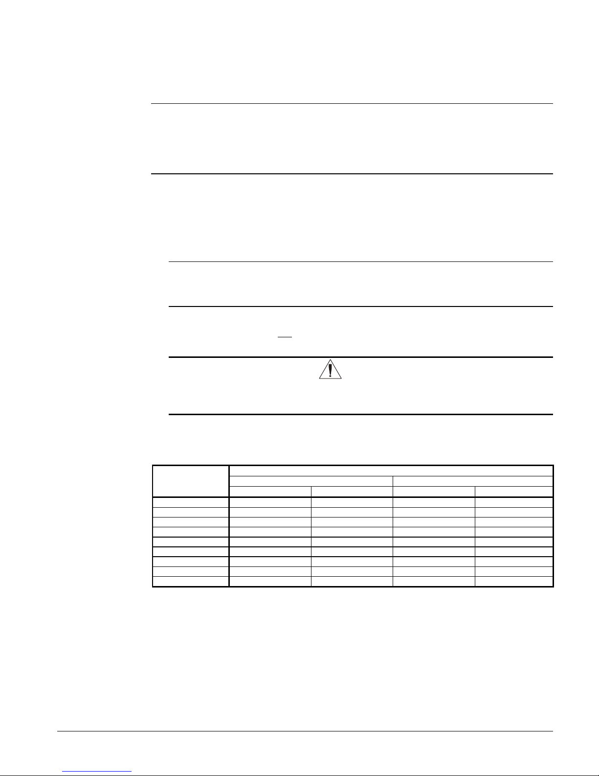
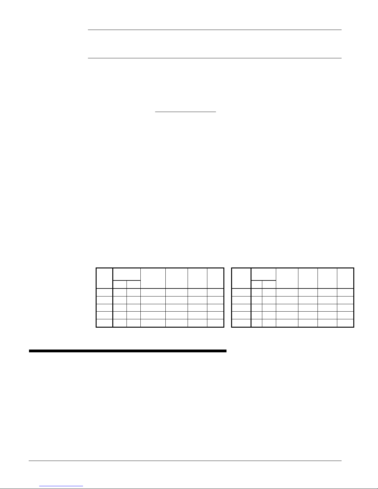
Table 12, Freeze Protection
Temperature
°°°°F (°°°°C)
20 (6.7) 16 18 11 12
10 (-12.2) 25 29 17 20
0 (-17.8) 33 36 22 24
-10 (-23.3) 39 42 26 28
-20 (-28.9) 44 46 30 30
-30 (-34.4) 48 50 30 33
-40 (-40.0) 52 54 30 35
-50 (-45.6) 56 57 30 35
-60 (-51.1) 60 60 30 35
Notes:
1. These figures are examples only and cannot be appropriate to every situation. Generally, for an extended margin of
protection, select a temperature at least 15°F lower than the expected lowest ambient temperature. Inhibitor levels
should be adjusted for solutions less than 25% glycol.
2. Glycol of less than 25% concentration is not recommended because of the potential for bacterial growth and loss of
heat transfer efficiency.
For Freeze Protection For Burst Protection
Ethylene Glycol Propylene Glycol Ethylene Glycol Propylene Glycol
Percent Volume Glycol Concentration Required
IMM AGS-2 21
Page 22
Operating Limits:
Maximum standby ambient temperature, 130°F (55°C)
Maximum operating ambient temperature, see below
Minimum operating ambient temperature (standard), 35°F (2°C)
Minimum operating ambient temperature (optional low-ambient control), 0°F (-18°C)
Leaving chilled water temperature, 40°F to 60°F (4°C to 16°C)
Leaving chilled fluid range (with anti-freeze), 20°F to 60°F (-7°C to 16°C). Unloading is
not permitted with fluid leaving temperatures below 30°F (-1°C).
Operating Delta-T range, 6 degrees F to 16 degrees F (10.8 C to 28.8 C)
Maximum operating inlet fluid temperature, 76°F (24°C)
Maximum startup inlet fluid temperature, 90°F (32°C)
Maximum non-operating inlet fluid temperature, 100°F (38°C)
NOTE: Contact the local McQuay sales office for operation outside any of these limits.
Maximum Operating Ambient Temperatures
Standard Efficiency, designated by a "0" as the last digit in the model number (such as
AGS 170C) are designed for operation up to 125 degrees. Significant unloading above 115
degrees can occur depending on a variety of factors. Contact your sales representative for
performance above 115 degrees. Additional unloading can result with leaving water
temperatures above 45 degrees.
High Efficiency, designated by a "5" as the last digit in the model number (such as AGS
175C) are designed for operation up to 125 degrees without unloading for leaving water
temperatures between 40 and 45 degrees Fahrenheit. Contact your sales representative for
evaporator duty outside of this range. The High Efficiency models have larger components,
and/or more fans than the comparable Standard Efficiency models. This results in
improved efficiency and the ability to operate at higher ambient air temperatures.
High Ambient Option, A factory-installed option that provides components allowing
operation in high ambient temperature locations. It can be applied to any unit and is
mandatory on:
1. All units with the optional VFD low ambient control.
2. All units that can have operating ambient temperatures above 115°F (46°C).
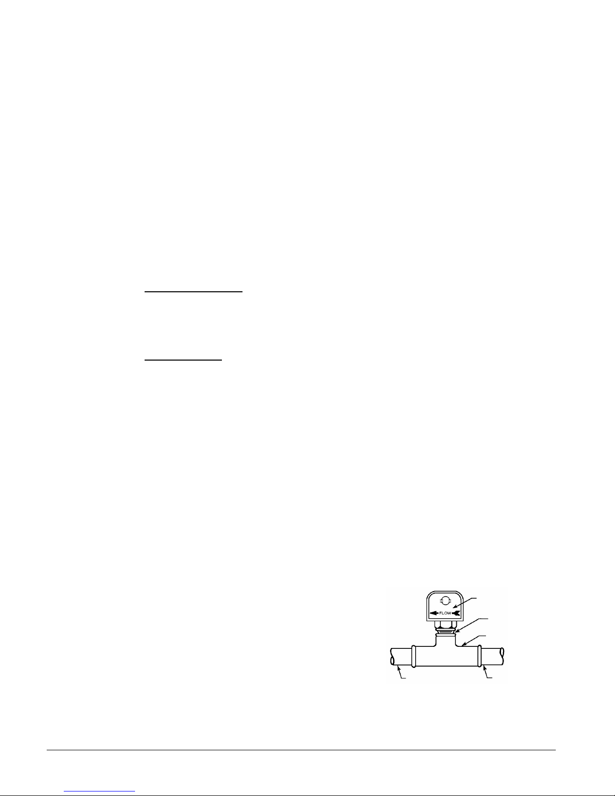
Flow Switch
A flow switch must be included in the
chilled water system to prove that there is
adequate water flow to the evaporator
before the unit can start. It also serves to
shut down the unit in the event that water
flow is interrupted in order to guard
against evaporator freeze-up.
A solid state flow switch that is factorymounted and wired in the chiller leaving
water nozzle is available as an option.
A flow switch for field mounting and
wiring in the leaving chilled water is also
available as an option from McQuay under
22 IMM AGS-2
Figure 17, Flow Switch
1 1/4" (32mm) pipe
dia. min. after switch
Flow direction marked
on switch
1" (25mm) NPT flow
switch connection
Tee
1 1/4" (32mm) pipe
dia. min. before switch
Page 23
ordering number 017503300. It is a paddle-type switch and adaptable to any pipe size from
Vent
Valve
Vibration
Valved
Against Freezing
Vibration
Valve
Valve
1" (25mm) to 8" (203mm) nominal.
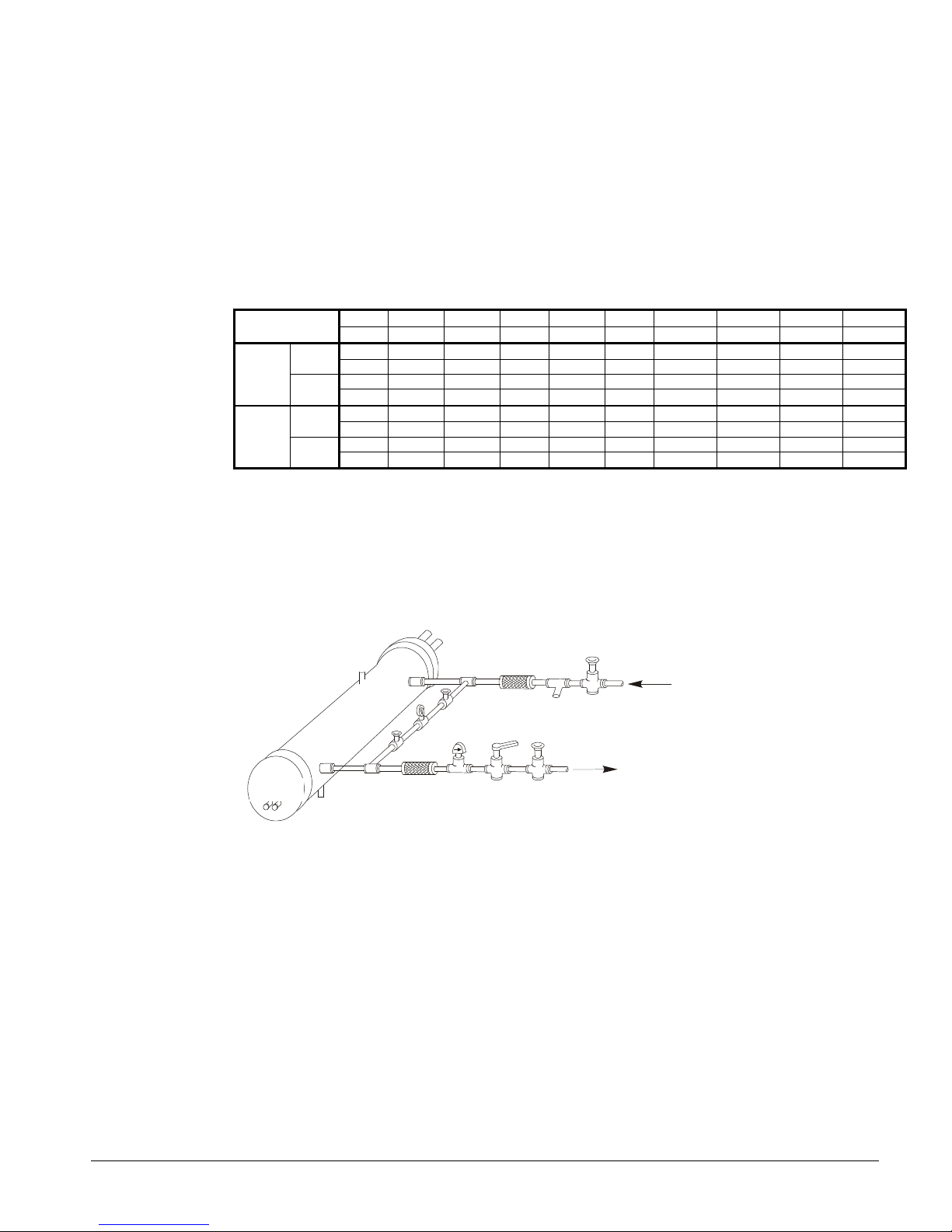
Certain minimum flow rates are required to close the switch and are listed in Table 13.
Installation should be as shown in Figure 18.
Electrical connections in the unit control center should be made at terminals 60 and 67 from
switch terminals Y and R. The normally open contacts of the flow switch should be wired
between these two terminals. Flow switch contact quality must be suitable for 24 VAC, low
current (16ma). Flow switch wire must be in separate conduit from any high voltage
conductors (115 VAC and higher) and have an insulation rating of 600 volts.
Table 13, Flow Switch Flow Rates
(NOTE !)
Min.
Adjst.
Max.
Adjst.
Flow
Flow Lpm 0.8 1.1 2.2 2.8 4.3 11.4 22.9 35.9 38.6
Flow
Flow Lpm 2.8 4.1 6.1 7.3 11.4 27.7 53.4 81.8 90.8
NOTES:
1. A segmented 3-inch paddle (1, 2, and 3 inches) is furnished mounted, plus a 6-inch paddle loose.
2. Flow rates for a 2-inch paddle trimmed to fit the pipe.
3. Flow rates for a 3-inch paddle trimmed to fit the pipe.
4. Flow rates for a 3-inch paddle.
5. Flow rates for a 6-inch paddle.
inch 1 1/4 1 1/2 2 2 1/2 3 4 5 6 8 Pipe Size
mm 32 (2) 38 (2) 51 63 (3) 76 102 (4) 127 (4) 153 (4) 204 (5)
gpm 5.8 7.5 13.7 18.0 27.5 65.0 125.0 190.0 205.0
Lpm 1.3 1.7 3.1 4.1 6.2 14.8 28.4 43.2 46.6
gpm 3.7 5.0 9.5 12.5 19.0 50.0 101.0 158.0 170.0
No
gpm 13.3 19.2 29.0 34.5 53.0 128.0 245.0 375.0 415.0
Lpm 3.0 4.4 6.6 7.8 12.0 29.1 55.6 85.2 94.3
gpm 12.5 18.0 27.0 32.0 50.0 122.0 235.0 360.0 400.0
No
Figure 18, Typical Field Water Piping
Suction
In
Gauge
Flow
Eliminator
Balancing
Pressure
Out
Liquid
Drain
Notes:
1. Connections for vent and drain fittings are located on the top and bottom of the evaporator.
2. Piping must be supported to avoid putting strain on the evaporator nozzles.
Eliminator
Switch
Water
Strainer
Gate
Flow
Gate
Protect All Field Piping
Flow
Refrigerant Charge
All packaged units are designed for use with R-134a and are shipped with a full operating
charge. The operating charge for each unit is shown in the Physical Data Tables beginning
on page 26 for packaged units, and page 60 for remote evaporator models. Model AGSCM/CB with remote evaporators are shipped with a full unit charge. Refrigerant must be
added in the field for the evaporator and for the refrigerant lines.
Glycol Solutions
When using glycol anti-freeze solutions the chiller's capacity, glycol solution flow rate, and
pressure drop through the evaporator can be calculated using the following formulas and
tables.
IMM AGS-2 23
Page 24
Note: The procedure below does not specify the type of glycol. Use the derate factors
()()(
)
found in Table 14 for corrections when using propylene glycol and those in Table 15 for
ethylene glycol.
1. Capacity - Cooling capacity is reduced from that with plain water. To find the
reduced value, multiply the chiller’s water system tonnage by the capacity correction
factor to find the chiller’s capacity when using glycol.
2. Flow - To determine flow (or Delta-T) knowing Delta-T (or flow) and capacity:
GPM−=
24
factorflowtons
TDelta
3. Pressure drop - To determine pressure drop through the evaporator when using
glycol, enter the water pressure drop curve at the water flow rate. Multiply the water
pressure drop found there by the "PD" factor to obtain corrected glycol pressure drop.
4. Power - To determine glycol system kW, multiply the water system kW by the factor
designated "Power".
Test coolant with a clean, accurate glycol solution hydrometer (similar to that found in
service stations) to determine the freezing point. Obtain percent glycol from the freezing
point table below. On glycol applications, the supplier normally recommends that a
minimum of 25% solution by weight be used for protection against corrosion or that
additional inhibitors should be employed.
NOTE: Do not use automotive grade antifreeze. Industrial grade glycols must be used.
Automotive antifreeze contains inhibitors that will cause plating on the copper tubes within
the chiller evaporator. The type and handling of glycol used must be consistent with local
codes.
Table 14, Ethylene Glycol Factors
Freeze
%
E.G.
Point
oF o
26 -3.3 0.996 0.998 1.036 1.097
10
18 -7.8 0.988 0.994 1.061 1.219
20
7 -13.9 0.979 0.991 1.092 1.352
30
-7 -21.7 0.969 0.986 1.132 1.532
40
-28 -33.3 0.958 0.981 1.182 1.748
50
Capacity Power Flow PD
C
Table 15, Propylene Glycol Factors
Freeze
% P.G.
10
20
30
40
50
Point
oF o
26 -3.3 0.991 0.996 1.016 1.092
19 -7.2 0.981 0.991 1.032 1.195
9 -12.8 0.966 0.985 1.056 1.345
-5 -20.6 0.947 0.977 1.092 1.544
-27 -32.8 0.932 0.969 1.140 1.906
Capacity Power Flow PD
C
Water Flow and Pressure Drop
Adjust the chilled water flow through the evaporator to meet specified conditions. The
flow rates must fall between the minimum and maximum values shown in the table on the
following page. Flow rates below the minimum values shown will result in laminar flow
that will reduce efficiency, cause erratic operation of the electronic expansion valve and
could cause low temperature cutouts. On the other hand, flow rates exceeding the
maximum values shown can cause erosion on the evaporator water connections and tubes.
Measure the chilled water pressure drop through the evaporator at field-installed pressure
taps. It is important not to include valve or strainer pressure drops in these readings.
24 IMM AGS-2
Page 25
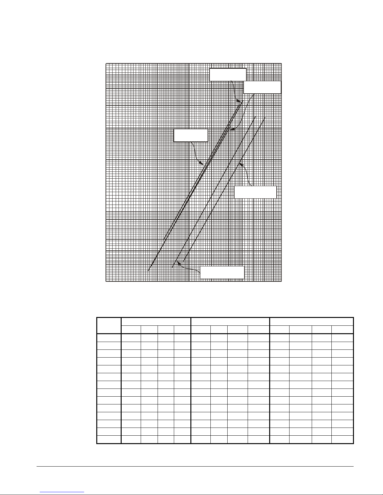
Figure 19, Evaporator Pressure Drops
200
300
400
500
600
700
800
900
1000
Flow Rate (GPM)
P
r
e
s
s
u
r
e
D
r
o
p
(
f
t
o
f
w
a
t
e
r
)
Flow Rate (L/s)
P
r
e
s
s
u
r
e
D
r
o
p
(
k
P
a
)
AGS Models
AGS Models
120, 130, 140
125, 135, 160
AGS Models
6 13 19 25 32 38 44 50 57 63
70
60
50
40
30
20
10
AGS Models
145
9
8
7
AGS Models
190, 195, 210
210
180
150
120
90
60
30
27
24
21
6
5
165, 170, 175, 180
4
100
Minimum/Nominal/Maximum Flow Rates
AGS
MODEL
120
125
130
135
140
145
160
165
170
175
180
190
195
210
MINIMUM FLOW NOMINAL FLOW MAXIMUM FLOW
gpm l/s ft kpa gpm l/s ft kpa gpm l/s ft kpa
175 11.1 4.6 13.7 280 17.7 10.6 31.6 467 29.5 26.5 79.1
182 11.5 4.9 14.6 292 18.5 11.8 35.2 486 30.8 29.2 87.2
188 11.9 5.3 15.8 300 19.0 12.9 38.5 501 31.7 30.4 90.7
196 12.4 5.6 16.7 314 19.9 13.5 40.3 524 33.1 33.5 100.0
201 12.7 5.9 17.6 321 20.3 13.6 40.6 535 33.8 30.4 90.7
215 13.6 6.9 20.6 343 21.7 16.1 48.0 572 36.2 40.2 119.9
227 14.4 7.2 21.5 363 23.0 17.1 51.0 606 38.3 43.0 128.4
241 15.2 4.8 14.4 385 24.4 11.3 33.8 642 40.6 28.6 85.3
252 16.0 5.2 15.7 403 25.5 12.3 36.7 672 42.6 31.1 92.7
259 16.4 5.7 17.0 414 26.2 12.9 38.5 690 43.7 32.6 97.2
269 17.1 5.9 17.7 431 27.3 13.9 41.4 718 45.5 35.0 104.5
278 17.6 5.2 15.5 445 28.2 12.3 36.7 742 47.0 30.7 91.6
285 18.1 5.4 16.1 457 28.9 12.8 38.2 761 48.2 32.6 97.3
302 19.1 5.9 17.6 483 30.6 14.3 42.7 805 50.9 34.5 103.0
18
15
12
IMM AGS-2 25
Page 26
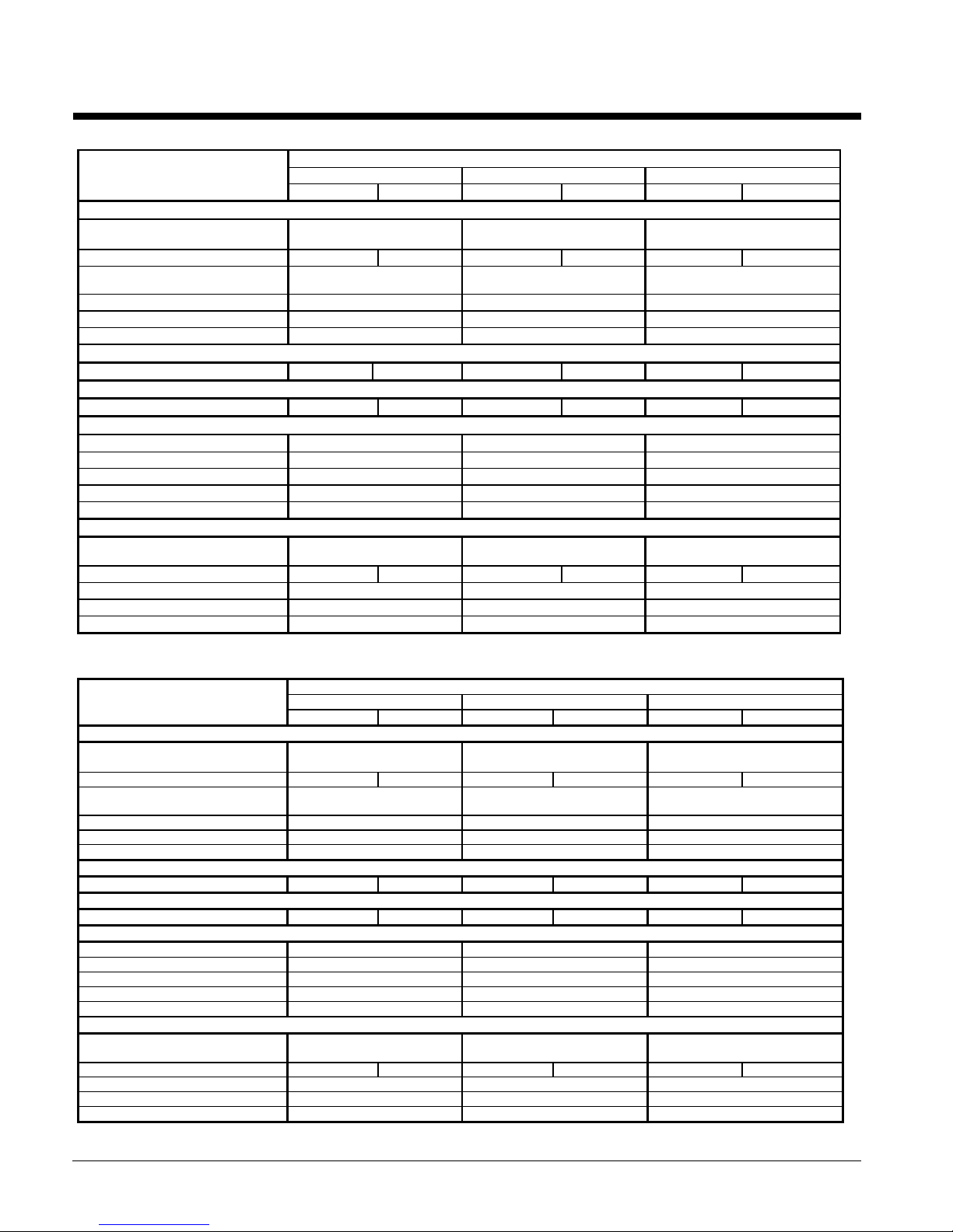
Physical Data, Standard Efficiency
Table 16, Physical Data, AGS 120C – AGS 140C
DATA
BASIC DATA
Unit Cap. @ 44°F LWT, 95°F Ambient
Temperature kW, (tons)
Unit Operating Charge lbs (kg) 131 (59) 131 (59) 131 (59) 131 (59) 131 (59) 131 (59)
Cabinet Dimensions
L x W x H, in. (mm)
Unit Operating Weight, lbs. (kg) 9452 (4291) 9452 (4291) 9452 (4291)
Unit Shipping Weight, lbs (kg) 9020 (4095) 9020 (4095) 9020 (4095)
Economizer No No No
COMPRESSORS, SCREW, SEMI-HERMETIC
Nominal Capacity, tons (kW) 60 (211) 60 (211) 60 (211) 70 (246) 70 (246) 70 (246)
CONDENSERS, HIGH EFFICIENCY FIN AND TUBE TYPE WITH INTEGRAL SUBCOOLER
Pumpdown Capacity, lbs (kg) 358 (163) 358 (163) 358 (163) 358 (163) 358 (163) 358 (163)
CONDENSER FANS, DIRECT DRIVE PROPELLER TYPE
No. of Fans – 30 in. Fan Dia. 8 8 8
No. of Motors -- hp (kW) 8 2 (1.5) 8 2 (1.5) 8 2 (1.5)
Fan & Motor RPM, 60Hz 1140 1140 1140
60 Hz Fan Tip Speed, fpm (m/s) 8950 (4224) 8950 (4224) 8950 (4224)
60 Hz Total Unit Airflow, cfm (l/s) 86900 (41020) 86900 (41020) 86900 (41020)
EVAPORATOR, DIRECT EXPANSION SHELL AND TUBE
Shell Dia.-Tube Length
in.(mm) - in. (mm)
Evaporator R-134a Charge lbs (kg) 1.95 (0.9) 1.95 (0.9) 1.95 (0.9) 1.95 (0.9) 1.95 (0.9) 1.95 (0.9)
Water Volume, gallons (liters) 49 (185) 49 (185) 49 (185)
Max. Water Pressure, psi (kPa) 152 (1048) 152 (1048) 152 (1048)
Max. Refrigerant Press., psi (kPa) 352 (2427) 352 (2427) 352 (2427)
120C 130C 140C
Ckt 1 Ckt 2 Ckt 1 Ckt 2 Ckt 1 Ckt 2
116.7 (410) 125.2 (440) 133.7 (470)
187 x 89 x 101
4750 x 2261 x 2565
15.5 x 82.4
(394 x 2093)
AGS MODEL NUMBER
187 x 89 x 101
4750 x 2261 x 2565
15.5 x 82.4
(394 x 2093)
187 x 89 x 101
4750 x 2261 x 2565
15.5 x 82.4
(394 x 2093)
Table 17, Physical Data, AGS 160C – AGS 180C
AGS MODEL NUMBER
DATA 160C 170C 180C
Ckt. 1 Ckt. 2 Ckt. 1 Ckt. 2 Ckt. 1 Ckt. 2
BASIC DATA
Unit Cap. @ 44°F LWT, 95°F Ambient
Temperature kW, (tons)
Unit Operating Charge, lbs (kg) 131 (59) 131 (59) 159 (72) 159 (72) 171 (78) 171 (78)
Cabinet Dim., L x W x H, in. (mm)
Unit Operating Weight, lbs. (kg) 10209 (4635) 11277 (5120) 11277 (5120)
Unit Shipping Weight, lbs (kg) 9484 (4306) 10552 (4791) 10552 (4791)
Economizer No No Yes
COMPRESSORS, SCREW, SEMI-HERMETIC
Nominal Capacity, tons (kW) 70 (246) 85 (299) 85 (299) 85 (299) 95 (334) 95 (334)
CONDENSERS, HIGH EFFICIENCY FIN AND TUBE TYPE WITH INTEGRAL SUBCOOLER
Pumpdown Capacity, lbs (kg) 358 (163) 358 (163) 399 (181) 399 (181) 399 (181) 399 (181)
CONDENSER FANS, DIRECT DRIVE PROPELLER TYPE
No. of Fans; 30 in. Fan Dia., 8 10 10
No. of Motors – hp (kW) 8 2 (1.5) 10 2 (1.5) 10 2 (1.5)
Fan & Motor RPM, 60Hz 1140 1140 1140
60 Hz Fan Tip Speed, fpm 8950 (4224) 8950 (4224) 8950 (4224)
60 Hz Total Unit Airflow, cfm (l/s) 86900 (41020) 108630 (51280) 108630 (51280)
EVAPORATOR, DIRECT EXPANSION SHELL AND TUBE
Shell Dia.,Tube Length in.(mm)
Evaporator R-134a Charge lbs (kg) 2.53 (1.1) 2.53 (1.1) 3.16 (1.4) 3.16 (1.4) 3.16 (1.4) 3.16 (1.4)
Water Volume, gallons (liters) 83 (314) 106 (401) 106 (401)
Max. Water Pressure, psi (kPa) 152 (1048) 152 (1048) 152 (1048)
Max. Refrigerant Press., psi (kPa) 352 (2427) 352 (2427) 352 (2427)
151.4 (532) 168.1 (591) 179.6 (631)
187 x 89 x 101
4750 x 2261 x 2565
19.4 x 82.4
(493 x 2093)
225 x 89 x 101
5715 x 2261 x 2565
19.4 x 105.1
(493 x 2670)
225 x 89 x 101
5715 x 2261 x 2565
19.4 x 105.1
(493 x 2670)
26 IMM AGS-2
Page 27
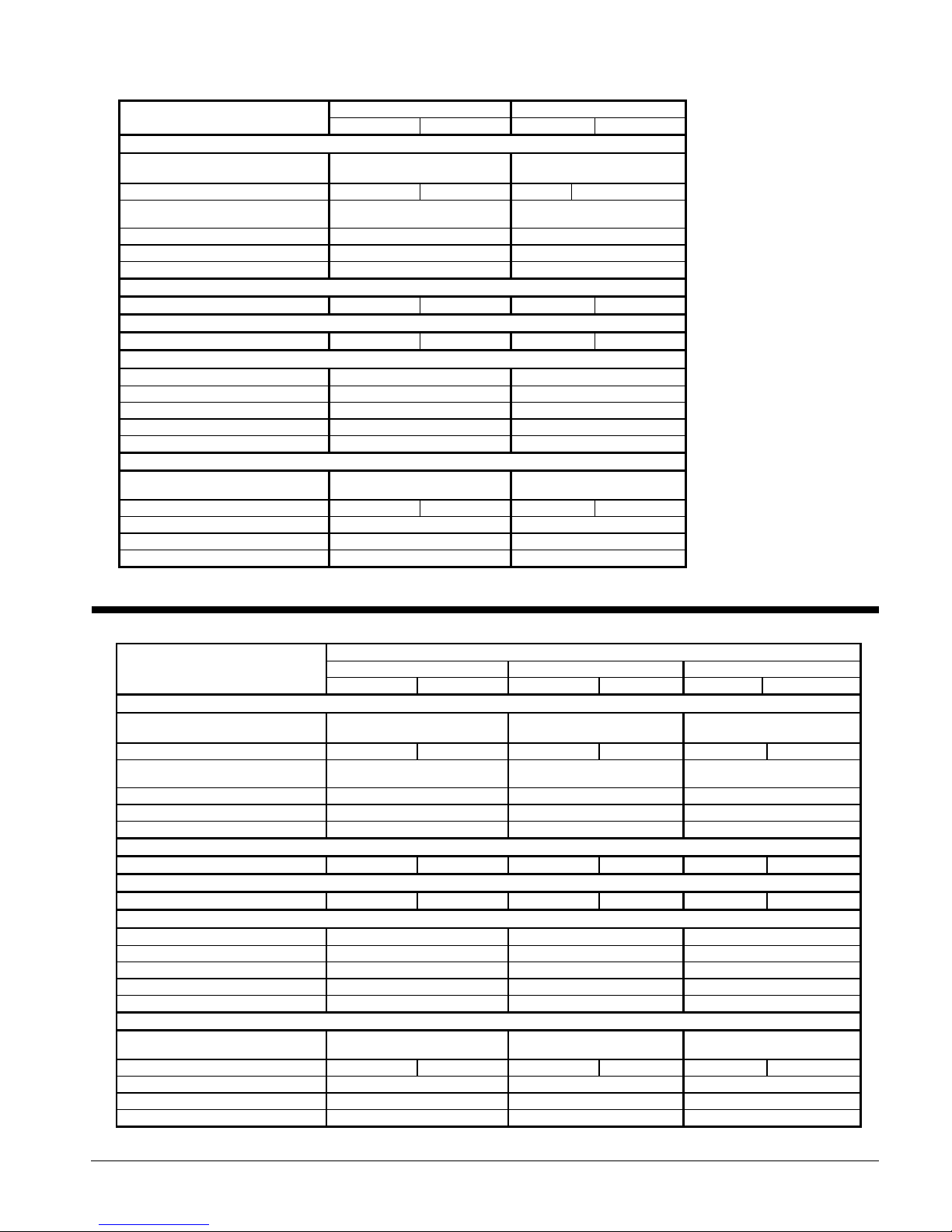
Table 18, Physical Data, AGS 190C – AGS 210C
DATA
BASIC DATA
Unit Cap. @ 44°F LWT, 95°F Ambient
Temperature kW, (tons)
Unit Operating Charge lbs (kg) 172 (78) 172 (78) 201 (91) 201 (91)
Cabinet Dimensions
L x W x H, in. (mm)
Unit Operating Weight, lbs. (kg) 11277 (5120) 11928 (5415)
Unit Shipping Weight, lbs (kg) 10552 (4791) 11011 (4999)
Economizer Yes Yes
COMPRESSORS, SCREW, SEMI-HERMETIC
Nominal Capacity, tons (kW) 95 (334) 95 (334) 95 (334) 95 (334)
CONDENSERS, HIGH EFFICIENCY FIN AND TUBE TYPE WITH INTEGRAL SUBCOOLER
Pumpdown Capacity, lbs (kg) 399 (181) 399 (181) 438 (199) 438 (199)
CONDENSER FANS, DIRECT DRIVE PROPELLER TYPE
No. of Fans -- 30 in. Fan Dia., 10 12
No. of Motors -- hp (kW) 10 2 (1.5) 12 2.5 (1.9)
Fan & Motor RPM, 60Hz 1140 1140
60 Hz Fan Tip Speed, fpm (m/s) 8950 (4224) 8950 (4224)
60 Hz Total Unit Airflow, cfm (l/s) 108630 (51280) 130360 (61530)
EVAPORATOR, DIRECT EXPANSION SHELL AND TUBE
Shell Dia.-Tube Length
in.(mm) - in. (mm)
Evaporator R-134a Charge lbs (kg) 3.63 (1.6) 3.63 (1.6) 3.63 (1.6) 3.63 (1.6)
Water Volume, gallons (liters) 106 (401) 104 (392)
Max. Water Pressure, psi (kPa) 152 (1048) 152 (1048)
Max. Refrigerant Press., psi (kPa) 352 (2427) 352 (2427)
AGS 190C AGS 210C
Ckt 1 Ckt 2 Ckt 1 Ckt 2
185.6 (653) 201.2 (707)
225 x 89 x 101
5715 x 2261 x 2565
19.4 x 105.1
(493 x 2670)
263 x 89 x 101
6680 x 2261 x 2565
19.4 x 105.1
(493 x 2670)
Physical Data, High Efficiency
Table 19, Physical Data, AGS 125C – AGS 145C
DATA
BASIC DATA
Unit Cap. @ 44°F LWT, 95°F Ambient
Temperature kW, (tons)
Unit Operating Charge lbs (kg) 159 (72) 159 (72) 159 (72) 159 (72) 159 (72) 159 (72)
Cabinet Dimensions
L x W x H, in. (mm)
Unit Operating Weight, lbs. (kg) 10930 (4962) 10930 (4962) 10485 (4760)
Unit Shipping Weight, lbs (kg) 10205 (4633) 10205 (4633) 9942 (4514)
Economizer No No No
COMPRESSORS, SCREW, SEMI-HERMETIC
Nominal Capacity, tons (kW) 60 (211) 60 (211) 60 (211) 70 (246) 70 (246) 70 (246)
CONDENSERS, HIGH EFFICIENCY FIN AND TUBE TYPE WITH INTEGRAL SUBCOOLER
Pumpdown Capacity, lbs (kg) 399 (181) 399 (181) 399 (181) 399 (181) 399 (181) 399 (181)
CONDENSER FANS, DIRECT DRIVE PROPELLER TYPE
No. of Fans – 30 in. Fan Dia., 10, 30 (762) 10, 30 (762) 10, 30 (762)
No. of Motors -- hp (kW) 10 2 (1.5) 10 2 (1.5) 10 2 (1.5)
Fan & Motor RPM, 60Hz 1140 1140 1140
60 Hz Fan Tip Speed, fpm (m/s) 8950 (4224) 8950 (4224) 8950 (4224)
60 Hz Total Unit Airflow, cfm (l/s) 108630 (51280) 108630 (51280) 108630 (51280)
EVAPORATOR, DIRECT EXPANSION SHELL AND TUBE
Shell Dia.-Tube Length
in.(mm) - in. (mm)
Evaporator R-134a Charge lbs (kg) 2.53 (1.1) 2.53 (1.1) 2.53 (1.1) 2.53 (1.1) 2.44 (1.1) 2.44 (1.1)
Water Volume, gallons (liters) 83 (314) 83 (314) 62 (236)
Max. Water Pressure, psi (kPa) 152 (1048) 152 (1048) 152 (1048)
Max. Refrigerant Press., psi (kPa) 352 (2427) 352 (2427) 352 (2427)
125C 135C 145C
Ckt 1 Ckt 2 Ckt 1 Ckt 2 Ckt 1 Ckt 2
121.6 (428) 130.9 (460) 143.0 (503)
225 x 89 x 101
5715 x 2261 x 2565
19.4 x 82.4
(493 x 2093)
AGS MODEL NUMBER
225 x 89 x 101
5715 x 2261 x 2565
19.4 x 82.4
(493 x 2093)
225 x 89 x 101
5715 x 2261 x 2565
19.4 x 105.1
(493 x 2670)
IMM AGS-2 27
Page 28

Table 20, Physical Data, AGS 165C – AGS 195C
DATA
BASIC DATA
Unit Cap. @ 44°F LWT, 95°F Ambient
Temperature kW, (tons)
Unit Operating Charge lbs (kg) 186 (84) 186 (84) 186 (84) 186 (84) 201 (91) 201 (91)
Cabinet Dimensions
L x W x H, in. (mm)
Unit Operating Weight, lbs. (kg) 11928 (5415) 11277 (5120) 11277 (5120)
Unit Shipping Weight, lbs (kg) 11011 (4999) 11011 (4999) 11011 (4999)
Economizer N0 N0 Yes
COMPRESSORS, SCREW, SEMI-HERMETIC
Nominal Capacity, tons (kW) 70 (246) 85 (299) 85 (299) 85 (299) 95 (334) 95 (334)
CONDENSERS, HIGH EFFICIENCY FIN AND TUBE TYPE WITH INTEGRAL SUBCOOLER
Pumpdown Capacity, lbs (kg) 438 (199) 438 (199) 438 (199) 438 (199) 438 (199) 438 (199)
CONDENSER FANS, DIRECT DRIVE PROPELLER TYPE
No. of Fans – 30 in. Fan Dia. 12 12 12
No. of Motors -- hp (kW) 12 2 (1.5) 12 2 (1.5) 12 2 (1.5)
Fan & Motor RPM, 60Hz 1140 1140 1140
60 Hz Fan Tip Speed, fpm (m/s) 8950 (4224) 8950 (4224) 8950 (4224)
60 Hz Total Unit Airflow, cfm (l/s) 130360 (61530) 130360 (61530) 130360 (61530)
EVAPORATOR, DIRECT EXPANSION SHELL AND TUBE
Shell Dia.-Tube Length
in.(mm) - in. (mm)
Evaporator R-134a Charge lbs (kg) 3.16 (1.4) 3.16 (1.4) 3.16 (1.4) 3.16 (1.4) 3.16 (1.4) 3.16 (1.4)
Water Volume, gallons (liters) 106 (401) 106 (401) 106 (401)
Max. Water Pressure, psi (kPa) 152 (1048) 152 (1048) 152 (1048)
Max. Refrigerant Press., psi (kPa) 352 (2427) 352 (2427) 352 (2427)
165C 175C 195C
Ckt 1 Ckt 2 Ckt 1 Ckt 2 Ckt 1 Ckt 2
160.5 (564) 172.5 (607) 190.3 (669)
263 x 89 x 101
6680 x 2261 x 2565
19.4 x 105.1
(493 x 2670)
AGS MODEL NUMBER
263 x 89 x 101
6680 x 2261 x 2565
19.4 x 105.1
(493 x 2670)
263 x 89 x 101
6680 x 2261 x 2565
19.4 x 105.1
(493 x 2670)
28 IMM AGS-2
Page 29
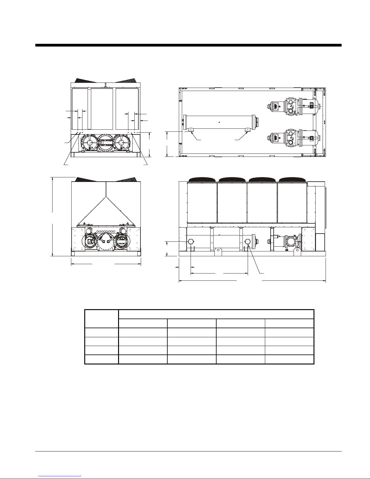
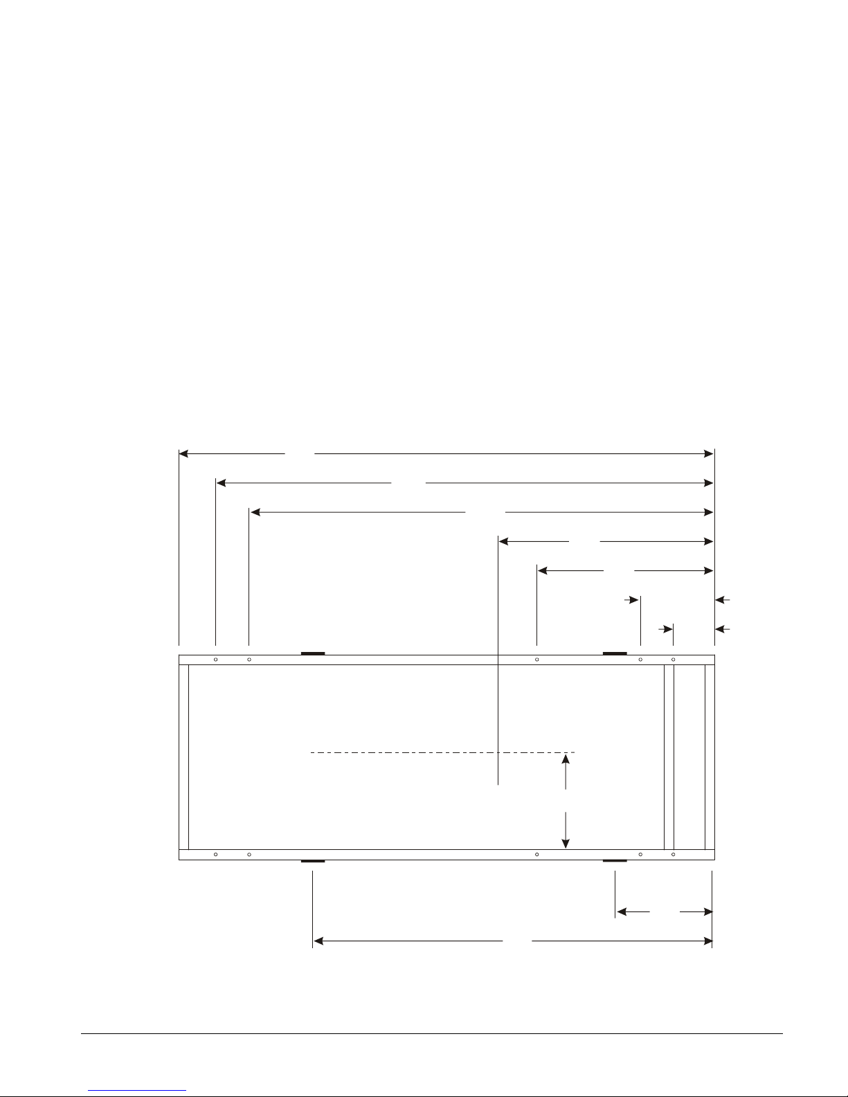
Dimensional Data
" A "
" B "
18.4
(467.4)
" C " VICTAULIC CONNECTION
" D "
INLET
Figure 20, Dimensions, AGS 120CS/H – AGS 160CS/H
Note: See p age 13 for lift ing locations , mount ing locations , weig ht s and m ounting loads.
6.0 (152.4)
8.5 (215.9)
0.875 (22.2)
KNOCK-OUT
( QTY 4 TOTAL)
100.4
(2550.2)
CONTROL
PANEL
FIELD CONTROL
CONNECTION
POWER
PANEL
88.5 (2247.9)
POWER
PANEL
POWER ENTRY
8.0 (203.2)
7.2 (182.9)
31.5
(800.1)
OUTLET
3307127-00-01
186.6 (4739.6)
UNIT
SIZE
AGS120C
AGS130C
AGS140C
AGS160C
" A " " B " " C " " D "
15.2 (386.1) 72.3 (1836.4) 6 (152.4) 32.1 (815.3)
15.2 (386.1) 72.3 (1836.4) 6 (152.4) 32.1 (815.3)
15.2 (386.1) 72.3 (1836.4) 6 (152.4) 32.1 (815.3)
16.2 (411.5) 70.3 (1785.6) 8 (203.2) 30.1 (764.5)
Dimensions In (mm)
IMM AGS-2 29
Page 30

Figure 21, Dimensions, AGS 125CS/H –190CS/H
" A "
" B "
(467.4)
"C " VICTAULIC CONNECTION
" D "
INLET
Note: See page13 f or lifting lo cations, mounting lo cations, weights and mountin g loads.
6.0 (152.4)
8.5 (215.9)
0.875 (22.2)
KNOCK OUT
( QTY 4 TOTAL)
100.4
(2550.2)
CONTROL
PANEL
CONNECTION
330712701-00-02
POWER
PANEL
88.5 (2248.9)
POWER
POWER ENTRYFIELD CONTROL
PANEL
8.0 (203.2)
7.2 (182.9)
31.5
(800.1)
18.4
OUTLET
224.8 (5709.9)
UNIT
SIZE
AGS125C
AGS135C
AGS145C
AGS170C
AGS180C
AGS190C
Dimensions In (mm)
" A " " B " " C " " D "
39.3 (998.2) 70.3 (1785.6) 8 (203.2) 30.1 (764.5)
39.3 (998.2) 70.3 (1785.6) 8 (203.2) 30.1 (764.5)
15.6 (396.2) 94.9 (2410.5) 6 (152.4) 32.1 (815.3)
16.7 (424.2) 92.9 (2359.7) 8 (203.2) 30.1 (764.5)
16.7 (424.2) 92.9 (2359.7) 8 (203.2) 30.1 (764.5)
16.7 (424.2) 92.9 (2359.7) 8 (203.2) 30.1 (764.5)
30 IMM AGS-2
Page 31

Figure 22 , Dimensions, AGS 165CS/H –210CS/H
" A "
" B "
" C " VICTAULIC CONNECTION
" D "
INLET
Note: See page 13 for lifti ng locations, mounting l ocations, weights and mo unting loads.
6.0 (152.4)
8.5 (215.9)
0.875 (22.2)
KNOCK OUT
( QTY 4 TOTAL)
100.4
(2550.2)
FIELD CONTROL
CONNECTION
3307127-00-03
POWER
PANEL
88.5 (2247.9)
POWER
PANEL
POWER ENTRY
8.0 (203.2)
7.2 (182.9)
31.5
(800.1)
18.4 (467.4)
OUTLET
263.0 (6680.2)
UNIT
SIZE
AGS165C
AGS175C
AGS195C
AGS210C
Dimensions In (mm)
" A " " B " " C " " D "
54.9 (1394.5) 92.9 (2359.7) 8 (203.2) 30.1 (764.5)
54.9 (1394.5) 92.9 (2359.7) 8 (203.2) 30.1 (764.5)
54.9 (1394.5) 92.9 (2359.7) 8 (203.2) 30.1 (764.5)
54.9 (1394.5) 92.9 (2359.7) 8 (203.2) 30.1 (764.5)
IMM AGS-2 31
Page 32

Electrical Data
Field Wiring
General
Wiring must comply with all applicable codes and ordinances. Warranty does not cover
damage to the equipment caused by wiring not complying with specifications.
An open fuse indicates a short, ground, or overload. Before replacing a fuse or restarting a
compressor or fan motor, the trouble must be found and corrected.
Copper wire is required for all power lead terminations at the unit, and copper must be used for
all other wiring to the unit.
AGS units can be ordered with main power wiring for either multiple-point power (standard)
or single-point connection (optional).
If the standard multiple-point power wiring is ordered, two separate power connections are
made to power blocks (or optional circuit breaker disconnects) in power panel. See the
dimension drawings beginning on page 29 for entry locations. Separate disconnects are
required for each electrical circuit if the McQuay optional factory-mounted disconnects are not
ordered.
If the optional single-point power connection is ordered, a single power connection is made to
a power block (or optional circuit breaker disconnect) in the unit power panel. A separate
disconnect is required if the McQuay optional factory-mounted disconnect is not ordered.
Isolation circuit breakers for each circuit are included.
It can be desirable to have the unit evaporator heaters on a separate disconnect switch from the
main unit power supply so that the unit power can be shut down without defeating the freeze
protection provided by the evaporator heaters. See the field wiring diagram on page 42 for
connection details.
The 115-volt control transformer is factory mounted and wired.
CAUTION
If a separate disconnect is used for the 115V supply to the unit, it must power the entire
control circuit, not just the evaporator heaters. It must be clearly marked so that it is not
accidentally shut off during cold seasons. Freeze damage to the evaporator could result.
If the evaporator is drained for winter freeze protection, the heaters must be de-energized
to prevent heater burnout.
CAUTION
AGS unit compressors are single-direction rotation compressors and can be damaged if
rotated in the wrong direction. For this reason, proper phasing of electrical power is
important. Electrical phasing must be A, B, C for electrical phases 1, 2 and 3 (A=L1,
B=L2, C=L3) for single or multiple point wiring arrangements. The solid-state starters
contain phase reversal protection. DO NOT ALTER THE WIRING TO THE
STARTERS.
32 IMM AGS-2
Page 33

Table 21, AGS 120C – AGS 210C, Electrical Data, Single-Point
AGS
UNIT
SIZE
120C 380 60 320 400 MCM 400 400
125C 380 60 328 400 MCM 400 450
130C 380 60 342 400 MCM 400 450
135C 380 60 350 400 MCM 400 450
140C 380 60 359 2-250 MCM 400 500
145C 380 60 367 2-250 MCM 450 500
160C 380 60 400 2-250 MCM 450 500
165C 380 60 416 2-300 MCM 500 500
170C 380 60 441 2-300 MCM 500 600
175C 380 60 449 2-300 MCM 500 600
VOLTS HZ
208 581 (2) 350 MCM 700 800
230 526 (2) 300 MCM 600 700
460 279 300 MCM 350 350
575 211 4/0 AWG 250 250
208 595 (2) 350 MCM 700 800
230 539 (2) 300 MCM 600 700
460 285 300 MCM 350 350
575 216 4/0 AWG 250 300
208 625 (2) 300 MCM 700 800
230 563 (2) 300 MCM 700 800
460 291 350 MCM 350 400
575 222 4/0 AWG 250 300
208 639 (2) 400 MCM 800 800
230 576 (2) 350 MCM 700 800
460 298 350 MCM 350 400
575 227 4/0 AWG 250 300
208 660 (2) 400 MCM 800 800
230 593 (2) 350 MCM 700 800
460 301 350 MCM 350 400
575 231 250 MCM 300 300
208* 674 (2) 400 MCM 800 800
230 606 (2) 350 MCM 700 800
460 308 350 MCM 350 400
575 236 250 MCM 300 300
208* 716 (2) 2-250 MCM 800 1000
230 646 (2) 400 MCM 800 800
460 325 400 MCM 400 450
575 255 250 MCM 300 350
208* 745 (2) 2-250 MCM 1000 1000
230 672 (2) 400 MCM 800 800
460 338 400 MCM 400 450
575 265 300 MCM 300 350
208* 775 (2) 2-250 MCM 1000 1000
230 701 (2) 400 MCM 800 800
460 351 400 MCM 400 450
575 279 300 MCM 350 350
208* 790 (2) 2-250 MCM 1000 1000
230 714 (2) 2-250 MCM 800 800
460 357 2-250 MCM 400 450
575 284 300 MCM 350 350
MINIMUM
CIRCUIT
AMPACITY
(MCA)
POWER
SUPPLY
(NOTE 1)
FIELD WIRE
Continued on next page.
FIELD FUSE SIZE or
HACR BREAKER SIZE
RECOM-
MENDED
MAXIMUM
IMM AGS-2 33
Page 34

AGS
UNIT
SIZE
180C 380 60 469 (2)-250 MCM 600 600
190C 380 60 469 (2)-250 MCM 600 600
195C 380 60 479 (2)-250 MCM 600 600
210C 380 60 493 (2)-250 MCM 600 600
Notes
1. See Note 1 on page 47 for explanation of wiring nomenclature.
2. Table based on 75°C field wire.
3. A “HACR” breaker is a circuit breaker designed for use on equipment with multiple motors.
4. Complete notes are on page 47.
VOLTS HZ
208* 853 (2) 2-300 MCM 1000 1000
230 772 (2) 2-250 MCM 1000 1000
460 380 2-250 MCM 450 500
575 301 350 MCM 350 400
208* 853 (2) 2-300 MCM 1000 1000
230 772 (2) 2-250 MCM 1000 1000
460 380 2-250 MCM 450 500
575 301 350 MCM 350 400
208* 871 (2) 2-300 MCM 1000 1000
230 788 (2) 2-250 MCM 1000 1000
460 387 2-250 MCM 450 500
575 306 350 MCM 350 400
208* 897 (2) 2-300 MCM 1000 1200
230 812 (2) 2-250 MCM 1000 1000
460 396 2-250 MCM 450 500
575 313 400 MCM 350 400
It stands for Heating, Air Conditioning, Refrigeration.
MINIMUM
CIRCUIT
AMPACITY
(MCA)
POWER
SUPPLY
(NOTE 1)
FIELD WIRE
FIELD FUSE SIZE or
HACR BREAKER SIZE
RECOM-
MENDED
MAXIMUM
Table 22, AGS 120C – AGS 210C, Electrical Data, Multiple-Point
ELECTRICAL CIRCUIT 1 (COMP 1) ELECTRICAL CIRCUIT 2 (COMP 2)
AGS
UNIT
VOLTS HZ
SIZE
208 320 400 MCM 400 500 320 400 MCM 400 500
230 289 350 MCM 350 450 289 350 MCM 350 450
120 380 60 176 3/0 AWG 225 300 176 3/0 AWG 225 300
460 154 2/0 AWG 200 250 154 2/0 AWG 200 250
575 116 1 AWG 150 200 116 1 AWG 150 200
208 327 400 MCM 400 500 327 400 MCM 400 500
230 296 350 MCM 350 450 296 350 MCM 350 450
125 380 60 180 3/0 AWG 225 300 180 3/0 AWG 225 300
460 157 2/0 AWG 200 250 157 2/0 AWG 200 250
575 119 1 AWG 150 200 119 1 AWG 150 200
208 320 400 MCM 400 500 363 2-250 MCM 450 600
230 289 350 MCM 350 450 327 400 MCM 400 500
130 380 60 176 3/0 AWG 225 300 198 3/0 AWG 250 300
460 154 2/0 AWG 200 250 166 2/0 AWG 200 250
575 116 1 AWG 150 200 128 1 AWG 175 200
208 327 400 MCM 400 500 371 2-250 MCM 450 600
230 296 350 MCM 350 450 333 400 MCM 400 500
135 380 60 180 3/0 AWG 225 300 202 4/0 AWG 250 300
460 157 2/0 AWG 200 250 169 2/0 AWG 200 250
575 119 1 AWG 150 200 130 1 AWG 175 200
208 363 2-250 MCM 450 600 363 2-250 MCM 450 600
230 327 400 MCM 400 500 327 400 MCM 400 500
140 380 60 198 3/0 AWG 250 300 198 3/0 AWG 250 300
460 166 2/0 AWG 200 250 166 2/0 AWG 200 250
575 128 1 AWG 175 200 128 1 AWG 175 200
MINIMUM
CIRCUIT
AMPS
(MCA)
POWER
SUPPLY
FIELD WIRE
FIELD FUSING
REC
FUSE
SIZE
MAX
FUSE
SIZE
MINIMUM
CIRCUIT
AMPS
(MCA)
Continued on next page.
POWER
SUPPLY
FIELD WIRE
FIELD FUSING
REC
FUSE
SIZE
MAX
FUSE
SIZE
34 IMM AGS-2
Page 35

ELECTRICAL CIRCUIT 1 (COMP 1) ELECTRICAL CIRCUIT 2 (COMP 2)
AGS
UNIT
VOLTS HZ
SIZE
208 371 2-250 MCM 450 600 371 2-250 MCM 450 600
230 333 400 MCM 400 500 333 400 MCM 400 500
145 380 60 202 4/0 AWG 250 300 202 4/0 AWG 250 300
460 169 2/0 AWG 200 250 169 2/0 AWG 200 250
575 130 1 AWG 175 200 130 1 AWG 175 200
208 363 2-250 MCM 450 600 420 2-300 MCM 500 700
230 327 400 MCM 400 500 379 2-250 MCM 450 600
160 380 60 198 3/0 AWG 250 300 239 250 MCM 300 400
460 166 2/0 AWG 200 250 190 3/0 AWG 250 300
575 128 1 AWG 175 200 151 2/0 AWG 200 250
208 378 2-250 MCM 450 600 434 2-300 MCM 450 600
230 340 400 MCM 400 500 393 2-250 MCM 400 500
165 380 60 206 4/0 AWG 250 350 247 250 MCM 250 350
460 173 2/0 AWG 225 250 197 3/0 AWG 225 250
575 132 1/0 AWG 175 225 156 2/0 AWG 175 225
208 427 2-300 MCM 600 700 427 2-300 MCM 600 700
230 386 2-250 MCM 500 600 386 2-250 MCM 500 600
170 380 60 243 250 MCM 300 400 243 250 MCM 300 400
460 193 3/0 AWG 250 300 193 3/0 AWG 250 300
575 154 2/0 AWG 200 250 154 2/0 AWG 200 250
208 434 2-300 MCM 600 700 434 2-300 MCM 600 700
230 393 2-250 MCM 500 600 393 2-250 MCM 500 600
175 380 60 247 250 MCM 300 400 247 250 MCM 300 400
460 197 3/0 AWG 250 300 197 3/0 AWG 250 300
575 156 2/0 AWG 200 250 156 2/0 AWG 200 250
208 469 (2) 250 MCM 600 800 469 (2) 250 MCM 600 800
230 425 2-300 MCM 500 700 425 2-300 MCM 500 700
180 380 60 258 300 MCM 350 400 258 300 MCM 350 400
460 209 4/0 AWG 250 350 209 4/0 AWG 250 350
575 166 2/0 AWG 200 250 166 2/0 AWG 200 250
208 469 (2) 250 MCM 600 800 469 (2) 250 MCM 600 800
230 425 2-300 MCM 500 700 425 2-300 MCM 500 700
190 380 60 258 300 MCM 350 400 258 300 MCM 350 400
460 209 4/0 AWG 250 350 209 4/0 AWG 250 350
575 166 2/0 AWG 200 250 166 2/0 AWG 200 250
208 478 (2) 250 MCM 600 800 478 (2) 250 MCM 600 800
230 433 2-300 MCM 600 700 433 2-300 MCM 600 700
195 380 60 263 300 MCM 350 400 263 300 MCM 350 400
460 213 4/0 AWG 300 350 213 4/0 AWG 300 350
575 169 2/0 AWG 200 250 169 2/0 AWG 200 250
208 491 (2) 250 MCM 600 800 491 (2) 250 MCM 600 800
230 445 2-300 MCM 600 700 445 2-300 MCM 600 700
210 380 60 270 300 MCM 350 450 270 300 MCM 350 450
460 218 4/0 AWG 300 350 218 4/0 AWG 300 350
575 172 2/0 AWG 225 250 172 2/0 AWG 225 250
MINIMUM
CIRCUIT
AMPS
(MCA)
POWER
SUPPLY
FIELD WIRE
FIELD FUSING
REC
FUSE
SIZE
MAX
FUSE
SIZE
MINIMUM
CIRCUIT
AMPS
(MCA)
POWER
SUPPLY
FIELD WIRE
FIELD FUSING
REC
FUSE
SIZE
MAX
FUSE
SIZE
IMM AGS-2 35
Page 36

Table 23, AGS 120C – AGS 210C, Compressor and Condenser Fan Motor Amp Draw
AGS
UNIT
VOLTS HZ
SIZE
208 232 232 7.3 8 40.0
230 210 210 6.6 8 40.0
120 380 60 128 128 4.0 8 20.0
460 112 112 3.3 8 20.0
575 85 85 2.4 8 12.8
208 232 232 7.3 10 40.0
230 210 210 6.6 10 40.0
125 380 60 128 128 4.0 10 20.0
460 112 112 3.3 10 20.0
575 85 85 2.4 10 12.8
208 232 267 7.3 8 40.0
230 210 240 6.6 8 40.0
130 380 60 128 145 4.0 8 20.0
460 112 122 3.3 8 20.0
575 85 94 2.4 8 12.8
208 232 267 7.3 10 40.0
230 210 240 6.6 10 40.0
135 380 60 128 145 4.0 10 20.0
460 112 122 3.3 10 20.0
575 85 94 2.4 10 12.8
208 267 267 7.3 8 40.0
230 240 240 6.6 8 40.0
140 380 60 145 145 4.0 8 20.0
460 122 122 3.3 8 20.0
575 94 94 2.4 8 12.8
208 267 267 7.3 10 40.0
230 240 240 6.6 10 40.0
145 380 60 145 145 4.0 10 20.0
460 122 122 3.3 10 20.0
575 94 94 2.4 10 12.8
208 267 312 7.3 8 40.0
230 240 282 6.6 8 40.0
160 380 60 145 178 4.0 8 20.0
460 122 141 3.3 8 20.0
575 94 113 2.4 8 12.8
208 267 312 7.3 12 40.0
230 240 282 6.6 12 40.0
165 380 60 145 178 4.0 12 20.0
460 122 141 3.3 12 20.0
575 94 113 2.4 12 12.8
208 312 312 7.3 10 40.0
230 282 282 6.6 10 40.0
170 380 60 178 178 4.0 10 20.0
460 141 141 3.3 10 20.0
575 113 113 2.4 10 12.8
208 312 312 7.3 12 40.0
230 282 282 6.6 12 40.0
175 380 60 178 178 4.0 12 20.0
460 141 141 3.3 12 20.0
575 113 113 2.4 12 12.8
208 340 340 7.3 10 40.0
230 308 308 6.6 10 40.0
180 380 60 187 187 4.0 10 20.0
460 154 154 3.3 10 20.0
575 123 123 2.4 10 12.8
RATED LOAD AMPS
CIRCUIT #1 CIRCUIT #2
FAN
MOTORS
FLA
(EACH)
NO OF
FAN
MOTORS
Continued on next page.
L R A
FAN
MOTORS
(EACH)
36 IMM AGS-2
Page 37
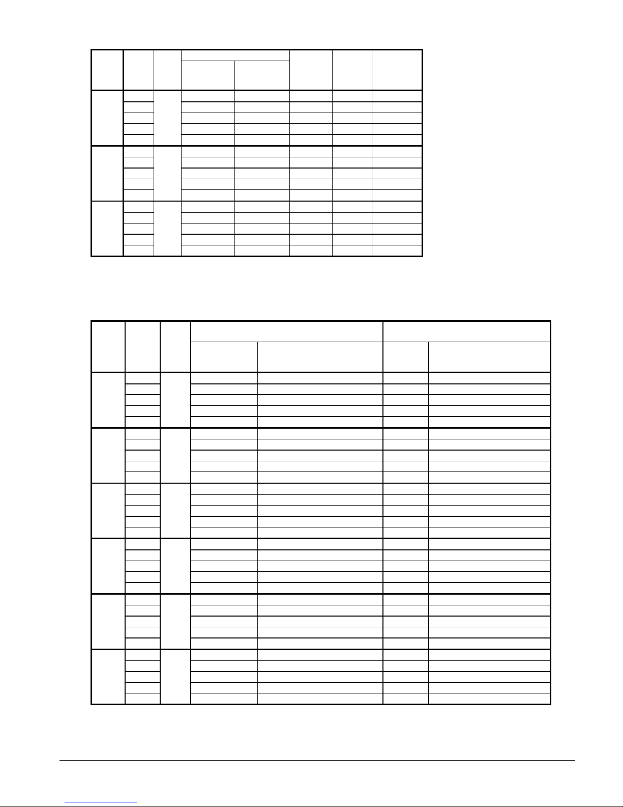
AGS
UNIT
VOLTS HZ
SIZE
208 340 340 7.3 10 40.0
230 308 308 6.6 10 40.0
190 380 60 187 187 4.0 10 20.0
460 154 154 3.3 10 20.0
575 123 123 2.4 10 12.8
208 340 340 7.3 12 40.0
230 308 308 6.6 12 40.0
195 380 60 187 187 4.0 12 20.0
460 154 154 3.3 12 20.0
575 123 123 2.4 12 12.8
208 340 340 11.0 12 46.0
230 308 308 9.9 12 46.0
210 380 60 187 187 6.0 12 25.0
460 154 154 4.1 12 23.0
575 123 123 3.0 12 20.0
NOTES:
1. Table based on 75°C field wire.
2. Complete notes are on page on page 47.
RATED LOAD AMPS
CIRCUIT #1 CIRCUIT #2
FAN
MOTORS
FLA
(EACH)
NO OF
FAN
MOTORS
L R A
FAN
MOTORS
(EACH)
Table 24, AGS 120C – AGS 210C, Customer Wiring Information With Single-Point Power
AGS
UNIT
VOLTS HZ
SIZE
208 800 1/0 – 750 MCM (4/C) 800 1/0 – 500 MCM (3/C)
230 800 1/0 – 750 MCM (4/C) 800 1/0 – 500 MCM (3/C)
120 380 60 400 #6 – 350 MCM (2/c) 400 3/0 – 500 MCM (2/C)
460 400 #6 – 350 MCM (2/c) 400 3/0 – 500 MCM (2/C)
575 400 #6 – 350 MCM (2/c) 250 #6 – 350 MCM (1/C)
208 800 1/0 – 750 MCM (4/C) 800 1/0 – 500 MCM (3/C)
230 800 1/0 – 750 MCM (4/C) 800 1/0 – 500 MCM (3/C)
125 380 60 400 #6 – 350 MCM (2/C) 400 3/0 – 500 MCM (2/C)
460 400 #6 – 350 MCM (2/C) 400 3/0 – 500 MCM (2/C)
575 400 #6 – 350 MCM (2/C) 250 #6 – 350 MCM (1/C)
208 800 1/0 – 750 MCM (4/C) 800 1/0 – 500 MCM (3/C)
230 800 1/0 – 750 MCM (4/C) 800 1/0 – 500 MCM (3/C)
130 380 60 400 #6 – 350 MCM (2/C) 400 3/0 – 500 MCM (2/C)
460 400 #6 – 350 MCM (2/C) 400 3/0 – 500 MCM (2/C)
575 400 #6 – 350 MCM (2/C) 250 #6 – 350 MCM (1/C)
208 800 1/0 – 750 MCM (4/C) 800 1/0 – 500 MCM (3/C)
230 800 1/0 – 750 MCM (4/C) 800 1/0 – 500 MCM (3/C)
135 380 60 400 #6 – 350 MCM (2/C) 400 3/0 – 500 MCM (2/C)
460 400 #6 – 350 MCM (2/C) 400 3/0 – 500 MCM (2/C)
575 400 #6 – 350 MCM (2/C) 250 #6 – 350 MCM (1/C)
208 800 1/0 – 750 MCM (4/C) 800 1/0 – 500 MCM (3/C)
230 800 1/0 – 750 MCM (4/C) 800 1/0 – 500 MCM (3/C)
140 380 60 400 #6 – 350 MCM (2/C) 400 3/0 – 500 MCM (2/C)
460 400 #6 – 350 MCM (2/C) 400 3/0 – 500 MCM (2/C)
575 400 #6 – 350 MCM (2/C) 250 #6 – 350 MCM (1/C)
208 800 1/0 – 750 MCM (4/C) 800 1/0 – 500 MCM (3/C)
230 800 1/0 – 750 MCM (4/C) 800 1/0 – 500 MCM (3/C)
145 380 60 400 #6 – 350 MCM (2/C) 400 3/0 – 500 MCM (2/C)
460 400 #6 – 350 MCM (2/C) 400 3/0 – 500 MCM (2/C)
575 400 #6 – 350 MCM (2/C) 250 #6 – 350 MCM (1/C)
WIRING TO STANDARD UNIT POWER BLOCK
TERMINAL SIZE
AMPS
CONNECTOR WIRE RANGE
PER PHASE
(COPPER WIRE ONLY)
Continued on next page
WIRING TO OPTIONAL NONFUSED
MOLDED CASE SWITCH IN UNIT
SIZE
CONNECTOR WIRE RANGE
PER PHASE
(COPPER WIRE ONLY)
IMM AGS-2 37
Page 38

AGS
UNIT
SIZE
NOTE:
1. Terminal size amps are the maximum amps that the power block is rated for.
2. Complete notes are on page 47.
3. Data based on 75°C wire.
4. (2/C) notation means two cables per conduit.
VOLTS HZ
208 800 1/0 – 750 MCM (4/C) 800 1/0 – 500 MCM (3/C)
230 800 1/0 – 750 MCM (4/C) 800 1/0 – 500 MCM (3/C)
160 380 60 800 1/0 – 750 MCM (4/C) 600 3/0 – 500 MCM (2/C)
460 400 #6 – 350 MCM (2/C) 600 3/0 – 500 MCM (2/C)
575 400 #6 – 350 MCM (2/C) 600 3/0 – 500 MCM (2/C)
208 800 1/0 – 750 MCM (4/C) 800 1/0 – 500 MCM (3/C)
230 800 1/0 – 750 MCM (4/C) 800 1/0 – 500 MCM (3/C)
165 380 60 800 1/0 – 750 MCM (4/C) 600 3/0 – 500 MCM (2/C)
460 400 #6 – 350 MCM (2/C) 600 3/0 – 500 MCM (2/C)
575 400 #6 – 350 MCM (2/C) 600 3/0 – 500 MCM (2/C)
208 1000 1/0 – 750 MCM (4/C) 1200 250 – 500 MCM (4/C)
230 800 1/0 – 750 MCM (4/C) 800 1/0 – 800 MCM (2/C)
170 380 60 800 1/0 – 750 MCM (4/C) 600 3/0 – 500 MCM (2/C)
460 400 #6 – 350 MCM (2/C) 600 3/0 – 500 MCM (2/C)
575 400 #6 – 350 MCM (2/C) 400 3/0 – 500 MCM (2/C)
208 1000 1/0 – 750 MCM (4/C) 1200 250 – 500 MCM (4/C)
230 800 1/0 – 750 MCM (4/C) 800 1/0 – 800 MCM (2/C)
175 380 60 800 1/0 – 750 MCM (4/C) 600 3/0 – 500 MCM (2/C)
460 400 #6 – 350 MCM (2/C) 600 3/0 – 500 MCM (2/C)
575 400 #6 – 350 MCM (2/C) 400 3/0 – 500 MCM (2/C)
208 1000 1/0 – 750 MCM (4/C) 1200 250 – 500 MCM (4/C)
230 1000 1/0 – 750 MCM (4/C) 1200 250 – 500 MCM (4/C)
180 380 60 800 1/0 – 750 MCM (4/C) 600 3/0 – 500 MCM (2/C)
460 400 #6 – 350 MCM (2/C) 600 3/0 – 500 MCM (2/C)
575 400 #6 – 350 MCM (2/C) 400 3/0 – 500 MCM (2/C)
208 1000 1/0 – 750 MCM (4/C) 1200 250 – 500 MCM (4/C)
230 1000 1/0 – 750 MCM (4/C) 1200 250 – 500 MCM (4/C)
190 380 60 800 1/0 – 750 MCM (4/C) 600 3/0 – 500 MCM (2/C)
460 400 #6 – 350 MCM (2/C) 600 3/0 – 500 MCM (2/C)
575 400 #6 – 350 MCM (2/C) 400 3/0 – 500 MCM (2/C)
208 1000 1/0 – 750 MCM (4/C) 1200 250 – 500 MCM (4/C)
230 1000 1/0 – 750 MCM (4/C) 1200 250 – 500 MCM (4/C)
195 380 60 800 1/0 – 750 MCM (4/C) 600 3/0 – 500 MCM (2/C)
460 400 #6 – 350 MCM (2/C) 600 3/0 – 500 MCM (2/C0
575 400 #6 – 350 MCM (2/C) 400 3/0 – 500 MCM (2/C)
208 1000 1/0 – 750 MCM (4/C) 1200 250 – 500 MCM (4/C)
230 1000 1/0 – 750 MCM (4/C) 1200 250 – 500 MCM (4/C)
210 380 60 800 1/0 – 750 MCM (4/C) 600 3/0 – 500 MCM (2/C)
460 400 #6 – 350 MCM (2/C) 600 3/0 – 500 MCM (2/C)
575 400 #6 – 350 MCM (2/C) 400 3/0 – 500 MCM (2/C)
WIRING TO STANDARD UNIT POWER BLOCK
TERMINAL SIZE
AMPS
CONNECTOR WIRE RANGE
PER PHASE
(COPPER WIRE ONLY)
WIRING TO OPTIONAL NONFUSED
MOLDED CASE SWITCH IN UNIT
SIZE
AMPS
CONNECTOR WIRE RANGE
PER PHASE
(COPPER WIRE ONLY)
38 IMM AGS-2
Page 39

Table 25, AGS 120C – 210C, Wiring Information with Multiple-Point Power w/o Disconnect
AGS
UNIT
VOLTS HZ
SIZE
208 400 400 #6 – 350 MCM (2/C) #6 – 350 MCM (2/C)
230 400 400 #6 – 350 MCM (2/C) #6 – 350 MCM (2/C)
120 380 60 400 400 #6 – 350 MCM (2/C) #6 – 350 MCM (2/C)
460 400 400 #6 – 350 MCM (2/C) #6 – 350 MCM (2/C)
575 400 400 #6 – 350 MCM (2/C) #6 – 350 MCM (2/C)
208 400 400 #6 – 350 MCM (2/C) #6 – 350 MCM (2/C)
230 400 400 #6 – 350 MCM (2/C) #6 – 350 MCM (2/C)
125 380 60 400 400 #6 – 350 MCM (2/C) #6 – 350 MCM (2/C)
460 400 400 #6 – 350 MCM (2/C) #6 – 350 MCM (2/C)
575 400 400 #6 – 350 MCM (2/C) #6 – 350 MCM (2/C)
208 400 400 #6 – 350 MCM (2/C) #6 – 350 MCM (2/C)
230 400 400 #6 – 350 MCM (2/C) #6 – 350 MCM (2/C)
130 380 60 400 400 #6 – 350 MCM (2/C) #6 – 350 MCM (2/C)
460 400 400 #6 – 350 MCM (2/C) #6 – 350 MCM (2/C)
575 400 400 #6 – 350 MCM (2/C) #6 – 350 MCM (2/C)
208 400 400 #6 – 350 MCM (2/C) #6 – 350 MCM (2/C)
230 400 400 #6 – 350 MCM (2/C) #6 – 350 MCM (2/C)
135 380 60 400 400 #6 – 350 MCM (2/C) #6 – 350 MCM (2/C)
460 400 400 #6 – 350 MCM (2/C) #6 – 350 MCM (2/C)
575 400 400 #6 – 350 MCM (2/C) #6 – 350 MCM (2/C)
208 400 400 #6 – 350 MCM (2/C) #6 – 350 MCM (2/C)
230 400 400 #6 – 350 MCM (2/C) #6 – 350 MCM (2/C)
140 380 60 400 400 #6 – 350 MCM (2/C) #6 – 350 MCM (2/C)
460 400 400 #6 – 350 MCM (2/C) #6 – 350 MCM (2/C)
575 400 400 #6 – 350 MCM (2/C) #6 – 350 MCM (2/C)
208 400 400 #6 – 350 MCM (2/C) #6 – 350 MCM (2/C)
230 400 400 #6 – 350 MCM (2/C) #6 – 350 MCM (2/C)
145 380 60 400 400 #6 – 350 MCM (2/C) #6 – 350 MCM (2/C)
460 400 400 #6 – 350 MCM (2/C) #6 – 350 MCM (2/C)
575 400 400 #6 – 350 MCM (2/C) #6 – 350 MCM (2/C)
208 400 800 #6 – 350 MCM (2/C) 1/0 – 750 MCM (4/C)
230 400 400 #6 – 350 MCM (2/C) #6 – 350 MCM (2/C)
160 380 60 400 400 #6 – 350 MCM (2/C) #6 – 350 MCM (2/C)
460 400 400 #6 – 350 MCM (2/C) #6 – 350 MCM (2/C)
575 400 400 #6 – 350 MCM (2/C) #6 – 350 MCM (2/C)
208 400 800 #6 – 350 MCM (2/C) 1/0 – 750 MCM (4/C)
230 400 400 #6 – 350 MCM (2/C) #6 – 350 MCM (2/C)
165 380 60 400 400 #6 – 350 MCM (2/C) #6 – 350 MCM (2/C)
460 400 400 #6 – 350 MCM (2/C) #6 – 350 MCM (2/C)
575 400 400 #6 – 350 MCM (2/C) #6 – 350 MCM (2/C)
208 800 800 1/0 – 750 MCM (4/C) 1/0 – 750 MCM (4/C)
230 400 400 #6 – 350 MCM (2/C) #6 – 350 MCM (2/C)
170 380 60 400 400 #6 – 350 MCM (2/C) #6 – 350 MCM (2/C)
460 400 400 #6 – 350 MCM (2/C) #6 – 350 MCM (2/C)
575 400 400 #6 – 350 MCM (2/C) #6 – 350 MCM (2/C)
208 800 800 1/0 – 750 MCM (4/C) 1/0 – 750 MCM (4/C)
230 400 400 #6 – 350 MCM (2/C) #6 – 350 MCM (2/C)
175 380 60 400 400 #6 – 350 MCM (2/C) #6 – 350 MCM (2/C)
460 400 400 #6 – 350 MCM (2/C) #6 – 350 MCM (2/C)
575 400 400 #6 – 350 MCM (2/C) #6 – 350 MCM (2/C)
208 800 800 1/0 – 750 MCM (4/C) 1/0 – 750 MCM (4/C)
230 800 800 1/0 – 750 MCM (4/C) 1/0 – 750 MCM (4/C)
180 380 60 400 400 #6 – 350 MCM (2/C) #6 – 350 MCM (2/C)
460 400 400 #6 – 350 MCM (2/C) #6 – 350 MCM (2/C)
575 400 400 #6 – 350 MCM (2/C) #6 – 350 MCM (2/C)
TERMINAL SIZE (AMPS) CONNECTOR WIRE RANGE PER PHASE (COPPER WIRE ONLY)
CKT 1 CKT 2 CKT 1 CKT 2
Continued on next page
WIRING TO UNIT POWER BLOCK
IMM AGS-2 39
Page 40

AGS
UNIT
SIZE
NOTES:
1. Terminal size amps are the maximum amps that the power block is rated for.
2. See Table 26 for multiple point with Disconnect Switch connections.
3. Data based on 75°C wire.
4. (2/C) notation means two cables per conduit.
5. Complete notes are on page 47.
VOLTS HZ
208 800 800 1/0 – 750 MCM (4/C) 1/0 – 750 MCM (4/C)
230 800 800 1/0 – 750 MCM (4/C) 1/0 – 750 MCM (4/C)
190 380 60 400 400 #6 – 350 MCM (2/C) #6 – 350 MCM (2/C)
460 400 400 #6 – 350 MCM (2/C) #6 – 350 MCM (2/C)
575 400 400 #6 – 350 MCM (2/C) #6 – 350 MCM (2/C)
208 800 800 1/0 – 750 MCM (4/C) 1/0 – 750 MCM (4/C)
230 800 800 1/0 – 750 MCM (4/C) 1/0 – 750 MCM (4/C)
195 380 60 400 400 #6 – 350 MCM (2/C) #6 – 350 MCM (2/C)
460 400 400 #6 – 350 MCM (2/C) #6 – 350 MCM (2/C)
575 400 400 #6 – 350 MCM (2/C) #6 – 350 MCM (2/C)
208 800 800 1/0 – 750 MCM (4/C) 1/0 – 750 MCM (4/C)
230 800 800 1/0 – 750 MCM (4/C) 1/0 – 750 MCM (4/C)
210 380 60 400 400 #6 – 350 MCM (2/C) #6 – 350 MCM (2/C)
460 400 400 #6 – 350 MCM (2/C) #6 – 350 MCM (2/C)
575 400 400 #6 – 350 MCM (2/C) #6 – 350 MCM (2/C)
TERMINAL SIZE (AMPS) CONNECTOR WIRE RANGE PER PHASE (COPPER WIRE ONLY)
CKT 1 CKT 2 CKT 1 CKT 2
WIRING TO UNIT POWER BLOCK
Table 26, AGS 120C –210C, Wiring Data with Multiple-Point Power w/ Disconnect Switch
AGS
UNIT
SIZE
VOLTS HZ
208 400 400 3/0 – 500 MCM (2/C) 3/0 – 500 MCM (2/C)
230 400 400 3/0 – 500 MCM (2/C) 3/0 – 500 MCM (2/C)
120 380 60 250 250 #6 – 350 MCM (1/C) #6 – 350 MCM (1/C)
460 250 250 #6 – 350 MCM (1/C) #6 – 350 MCM (1/C)
575 150 150 #6 – 350 MCM (1/C) #6 – 350 MCM (1/C)
208 400 400 3/0 – 500 MCM (2/C) 3/0 – 500 MCM (2/C)
230 400 400 3/0 – 500 MCM (2/C) 3/0 – 500 MCM (2/C)
125 380 60 250 250 #6 – 350 MCM (1/C) #6 – 350 MCM (1/C)
460 250 250 #6 – 350 MCM (1/C) #6 – 350 MCM (1/C)
575 150 150 #6 – 350 MCM (1/C) #6 – 350 MCM (1/C)
208 400 400 3/0 – 500 MCM (2/C) 3/0 – 500 MCM (2/C)
230 400 400 3/0 – 500 MCM (2/C) 3/0 – 500 MCM (2/C)
130 380 60 250 250 #6 – 350 MCM (1/C) #6 – 350 MCM (1/C)
460 250 250 #6 – 350 MCM (1/C) #6 – 350 MCM (1/C)
575 150 150 #6 – 350 MCM (1/C) #6 – 350 MCM (1/C)
208 400 400 3/0 – 500 MCM (2/C) 3/0 – 500 MCM (2/C)
230 400 400 3/0 – 500 MCM (2/C) 3/0 – 500 MCM (2/C)
135 380 60 250 250 #6 – 350 MCM (1/C) #6 – 350 MCM (1/C)
460 250 250 #6 – 350 MCM (1/C) #6 – 350 MCM (1/C)
575 150 150 #6 – 350 MCM (1/C) #6 – 350 MCM (1/C)
208 400 400 3/0 – 500 MCM (2/C) 3/0 – 500 MCM (2/C)
230 400 400 3/0 – 500 MCM (2/C) 3/0 – 500 MCM (2/C)
140 380 60 250 250 #6 – 350 MCM (1/C) #6 – 350 MCM (1/C)
460 250 250 #6 – 350 MCM (1/C) #6 – 350 MCM (1/C)
575 150 150 #6 – 350 MCM (1/C) #6 – 350 MCM (1/C)
208 400 400 3/0 – 500 MCM (2/C) 3/0 – 500 MCM (2/C)
230 400 400 3/0 – 500 MCM (2/C) 3/0 – 500 MCM (2/C)
145 380 60 250 250 #6 – 350 MCM (1/C) #6 – 350 MCM (1/C)
460 250 250 #6 – 350 MCM (1/C) #6 – 350 MCM (1/C)
575 150 150 #6 – 350 MCM (1/C) #6 – 350 MCM (1/C)
TERMINAL SIZE (AMPS) CONNECTOR WIRE RANGE PER PHASE (COPPER WIRE ONLY)
CKT 1 CKT 2 CKT 1 CKT 2
Continued on next page
WIRING TO UNIT DISCONNECT SWITCH (MOLDED CASE SWITCH)
40 IMM AGS-2
Page 41

AGS
UNIT
SIZE
NOTE:
1. Terminal size amps are the maximum amps that the disconnect switch is rated for.
2. Data based on 75°C wire.
3. (2/C) notation means two cables per conduit.
4. Complete notes are on page 47.
VOLTS HZ
208 400 600 3/0 – 500 MCM (2/C) 3/0 – 500 MCM (2/C)
230 400 600 3/0 – 500 MCM (2/C) 3/0 – 500 MCM (2/C)
160 380 60 250 400 #6 – 350 MCM (1/C) 3/0 – 500 MCM (2/C)
460 250 250 #6 – 350 MCM (1/C) #6 – 350 MCM (1/C)
575 150 150 #6 – 350 MCM (1/C) #6 – 350 MCM (1/C)
208 400 600 3/0 – 500 MCM (2/C) 3/0 – 500 MCM (2/C)
230 400 600 3/0 – 500 MCM (2/C) 3/0 – 500 MCM (2/C)
165 380 60 250 400 #6 – 350 MCM (1/C) 3/0 – 500 MCM (2/C)
460 250 250 #6 – 350 MCM (1/C) #6 – 350 MCM (1/C)
575 150 150 #6 – 350 MCM (1/C) #6 – 350 MCM (1/C)
208 600 600 3/0 – 500 MCM (2/C) 3/0 – 500 MCM (2/C)
230 600 600 3/0 – 500 MCM (2/C) 3/0 – 500 MCM (2/C)
170 380 60 400 400 3/0 – 500 MCM (2/C) 3/0 – 500 MCM (2/C)
460 250 250 #6 – 350 MCM (1/C) #6 – 350 MCM (1/C)
575 250 250 #6 – 350 MCM (1/C) #6 – 350 MCM (1/C)
208 600 600 3/0 – 500 MCM (2/C) 3/0 – 500 MCM (2/C)
230 600 600 3/0 – 500 MCM (2/C) 3/0 – 500 MCM (2/C)
175 380 60 400 400 3/0 – 500 MCM (2/C) 3/0 – 500 MCM (2/C)
460 250 250 #6 – 350 MCM (1/C) #6 – 350 MCM (1/C)
575 250 250 #6 – 350 MCM (1/C) #6 – 350 MCM (1/C)
208 600 600 3/0 – 500 MCM (2/C) 3/0 – 500 MCM (2/C)
230 600 600 3/0 – 500 MCM (2/C) 3/0 – 500 MCM (2/C)
180 380 60 400 400 3/0 – 500 MCM (2/C) 3/0 – 500 MCM (2/C)
460 250 250 #6 – 350 MCM (1/C) #6 – 350 MCM (1/C)
575 250 250 #6 – 350 MCM (1/C) #6 – 350 MCM (1/C)
208 600 600 3/0 – 500 MCM (2/C) 3/0 – 500 MCM (2/C)
230 600 600 3/0 – 500 MCM (2/C) 3/0 – 500 MCM (2/C)
190 380 60 400 400 3/0 – 500 MCM (2/C) 3/0 – 500 MCM (2/C)
460 250 250 #6 – 350 MCM (1/C) #6 – 350 MCM (1/C)
575 250 250 #6 – 350 MCM (1/C) #6 – 350 MCM (1/C)
208 600 600 3/0 – 500 MCM (2/C) 3/0 – 500 MCM (2/C)
230 600 600 3/0 – 500 MCM (2/C) 3/0 – 500 MCM (2/C)
195 380 60 400 400 3/0 – 500 MCM (2/C) 3/0 – 500 MCM (2/C)
460 250 250 #6 – 350 MCM (1/C) #6 – 350 MCM (1/C)
575 250 250 #6 – 350 MCM (1/C) #6 – 350 MCM (1/C)
208 600 600 3/0 – 500 MCM (2/C) 3/0 – 500 MCM (2/C)
230 600 600 3/0 – 500 MCM (2/C) 3/0 – 500 MCM (2/C)
210 380 60 400 400 3/0 – 500 MCM (2/C) 3/0 – 500 MCM (2/C)
460 250 250 #6 – 350 MCM (1/C) #6 – 350 MCM (1/C)
575 250 250 #6 – 350 MCM (1/C) #6 – 350 MCM (1/C)
TERMINAL SIZE (AMPS) CONNECTOR WIRE RANGE PER PHASE (COPPER WIRE ONLY)
CKT 1 CKT 2 CKT 1 CKT 2
WIRING TO UNIT DISCONNECT SWITCH
IMM AGS-2 41
Page 42

Field Wiring Diagram
TB1
72
IF REMOTE STOP CONTROL
IS USED, REMOVE LEAD 897
897
60
66
AUTO
ON
MANUAL
60
68
AUTO
ON
MANUAL
71
4-20MA FOR
4-20MA FOR
GND
60
67
70
70
TIME
DISCONNECT
UNIT MAIN
120 VAC
1
2
120 VAC
81
75
FU4
FU5
FU7
85
2
120 VAC
24 VAC
ALARM BELL OPTION
BELL
COM
2
REMOTE EVAPORATOR ONLY
TB*1
93
2
120 VAC
SV
LIQUID LINE
EXV
JUNCTION
BLACK
WHITE
GREEN
EV
NOTE:
*TB11 = CIRCUIT #1
*TB21 = CIRCUIT #2
EXV 1 (TOP) - CIRCUIT #1
EXV 2 (BOTTOM) - CIRCUIT #2
Figure 23, Typical Field Wiring Diagram
3 PHASE
POWER
SUPPLY
(BY OTHERS)
TERMINAL BLOCK
FUSED CONTROL
CIRCUIT TRANSFORMER
GND LUG
TO COMPRESSOR(S)
AND FAN MOTORS
120 VAC
N
DISCONNECT FU7 IF SUPPLYING SEPARATE 120V SOURCE.
NOTE: ALL FIELD WIRING
TO BE INSTALLED AS NEC
CLASS 1 WIRING SYSTEM
WITH CONDUCTOR RATED
600 VOLTS
FACTORY SUPPLIED ALARM
ALARM BELL
OPTION
REMOTE STOP
SWITCH
(BY OTHERS)
ICE MODE
SWITCH
(BY OTHERS)
DISCONNECT
(BY OTHERS)
FIELD WIRED
ABR
ALARM BELL RELAY
CLOCK
15 A
FUSE
(BY OTHERS)
CHWR
EVAP. PUMP RELAY #1
(BY OTHERS)
120 VAC 1.0 AMP MAX
CHWR
EVAP. PUMP RELAY #2
(BY OTHERS)
120 VAC 1.0 AMP MAX
OFF
OFF
TB1
(115 VAC)
82
(24 VAC OR 30 VDC)
TB1-2
1 2
N
N
FROM TERM. 40 TO 53.
ALARM BELL
RELAY
NO
EVAP. FLOW
SWITCH
(BY OTHERS)
*MANDATORY IF FACTORY FLOW SWITCH OPTION IS NOT SELECTED.
DWG. 330590801 REV. 0D
42 IMM AGS-2
NOR. OPEN PUMP AUX.
CONTACTS (OPTIONAL)
EVAP. WATER RESET
(BY OTHERS)
DEMAND LIMIT
(BY OTHERS)
SOLENOID
DRIVER
+
-
+
-
BLACK
WHITE
GREEN
RED
NOTE:
BOX
RED
NOTE: See page 49 for additional
remote evaporator wiring
Page 43

Figure 24, AGS 120C - 210C Unit Controller Schematic
J11
J12
J13
J14
J15
J1
J2
812
801
J3
803
BLK
RED
BLK
RED
J4
J5
ID1
ID2
ID3
ID4
ID5
ID6
ID7
ID8
IDC1
808
809
810
811
CHWI
U
T
P
U
T
S
CONTROLLER
A+
GND
B-
813
C1
NO1
NO2
NO3
C4
NO4
NO5
NO6
WJ
802
C7
C7
NO8
NC8
NO7
GO
B1
B2
B3
GND
+VDC
S1
67
66
68
60
804
805
806
814
60
67
75
EVAPORATOR
EVAPORATOR
OUTSIDE AIR TEMP (S07)
DEMAND LIMIT (S10)
73
EVAP. WATER TEMP. RESET (S11)
EVAP. LEAVING WATER TEMP (S08)
EVAP. ENTERING WATER TEMP (S09)
MJ
4-20MA
4-20MA
800
75
60
PE
G
PE
SHIELD
69
BLK
RED
SHIELD
70
70
70
B4
BC4
B5
BC5
BLACK
WHITE
GROUND
PUMP 1
PUMP 2
71
72
PE
UNIT SWITCH
REMOTE SWITCH
EVAP. FLOW SWITCH
MODE SWITCH
FACTORY
INSTALLED
FLOW
SWITCH
807
MS1
897
BLU
800
RS1
C1
D IG IT A L O
C4
WHTBRN
UNIT
ALARM
C8
IMM AGS-2
43
Page 44

Unit Controller Schematic Continued
855
852
FU10
120V
120V
LINE
CONTACT
LOCATION
TERMINAL BLOCK
AND LEAD NUMBERS
85
82
81
60
75
2
SCHEM. 330590301 REV. 0D
CHWR
CHWR
2
1
TB1
1
1
2
2
60
60
60
75
821, 891
801, 807
800, 802, 813
2
2
2
75
897, 809
66
67
68
70
71
72
73
81
82
85
60
60
NOTE:
MJ
820, 822, 850
891
851, F2-2
83
854, F3-2
84
VFD ONLY
69
803
1
FU12
890
115V OUTLET
850
853
(p LAN) TO CIRCUIT CONTROL BOXES
BLACK
WHITE
GROUND
(TERMINATE AT EACH CONTROLLER)
EVAPORATOR PUMP 1
EVAPORATOR PUMP 2
UNIT ALARM
1 2
FU11
1 2
1 2
LINE 1
LOAD 1
822
823
824
829
830
83
T2
120V
1
526
24V
1
(SEE LINE 301)
(SEE LINE 307)
B
851
854
REC
W
G
HTR-EVAP
1TS2
LINE 2
LOAD 2
ABR
NO.
-301
MJ
-302
-303
-304
-305
-306
-307
-308
-309
-310
-311
-312
-313
-314
-315
-316
-317
-318
-319
-320
-321
-322
-323
-324
-325
-326
-327
-328
-329
-330
-331
-332
-333
-334
-335
-336
-337
-338
-339
-340
-341
-342
-343
-344
-345
-346
-347
-348
-349
-350
-351
-352
-353
-354
-355
-356
-357
-358
-359
-360
-361
-362
-363
-364
853, 890
852, 855
897, 830
812
810
811
806
804
805
814
829
823
824
TB1-75 THRU
TB1-89 ARE
FIELD
WIRING
TERMINALS.
PE
HEATER
2
1
2
C-BOX
HEATER
1
2
821820
(SEE LINE 306)
44
IMM AGS-2
Page 45
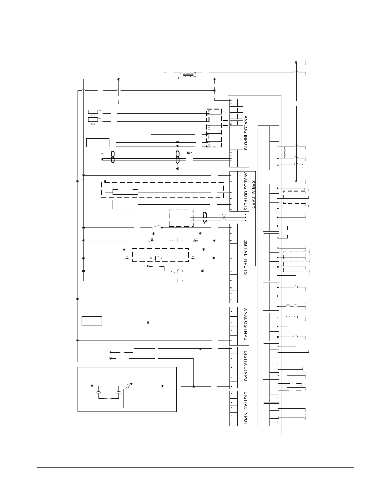
Figure 25, AGS 120C - 210C Circuit Controller Schematic
J2
121
J3
SHIELD
J5
ID1
ID2
ID3
ID4
ID5
ID6
ID7
ID8
IDC1
128
A+
GND
B-
J11
1
J12
C1
NO1
NO2
NO3
J13
C4
NO4
NO5
NO6
WJ
123
J14
C7
C7
NO8
NC8
J15
NO7
GO
B4
BC4
BC5
FAN 1
FAN 2
FAN 3
J4
J6
B6
B7
B8
GND
24V
113
RED
BLK
RED
VG
124
125
141
126
ID9
ID10
ID11
ID12
IDC9
142
N/A ON NON-VFD UNITS
129
131
21
WHT
DIFFERENTIAL PRESSURE SWITCH
PE
MHPR
MECHANICAL HIGH PRESSU RE FAULT
133
134
24
4-20MA
SLIDE LOAD
135
136
20
PE
J16
C9
NO9
NO10
NO11
J17
NO12
NC12
NO13
NC13
J18
C12
120
OHMS
1
FAN 4
FAN 5
MJ
MJ
ID13H
IDC13
ID14H
(LOWER LEVEL)
188
40
OIL SEP.
2) ONE HUNDRED SERIES FOR CIRCUIT #1
3) TWO HUNDRED SERIES FOR CIRCUIT #2
22
MJ
139
(SEE LINE 687)
0-10VDC
0-10VDC
CS
1
1
3
3
J5
J4
882
883
BLACK
WHITE
GREEN
D3
SCOM
SHLD
165
TB1-
GND
A+
B-
DETAIL 2 - THERMISTOR CARD
GUARDISTOR
J3-1
J3-2
REMOTE EVAP. ONLY.
IN SERIES WITH 170
185
142
TB1-28TB1-
29
143
143
29
165
91
91
165
TB1-
90
(SEE LINE 693)
TO T5
MJ
0-5 VDC
0-5 VDC
SLIDE LOAD
INDICATOR
116
20
122
EVAP PRESS TRANSDUCER (S01)
RED
WHT
BLK
DISCHARGE PRESS TRANS DUCER (S02)
RED
WHT
BLK
BIAS 5
21 VDC
1
DC GROUND
2
SUCTION TEMP. (S04)
DISCHARGE TEMP. (S05)
BIAS G
114
120
T3
120V
1
2
5
40
6
MJ
40
J1
G
J1
J2
J3
25
26
137
138
B5
PE
N/A ON NON-VFD UNITS
140
FAN VFD
EXV DRIVER
(SEE DETAIL 1)
CIRCUIT SWITCH
STARTER FAULT
127
164
VFD FAULT
INDICATOR
3
2
GREEN
MOTOR
170 171
1 2
LP*
NOTES: 1) * - REPRESENTS CIRCUIT
OLS
GRN
BLK
130
VGD
Y1
164
FLT
COM NO
SASB+
Y2
Y3
Y4
N/A ON VFD UNITS
C1
143
C4
C8
COMPRESSOR
SSS CONTACT
HEATER
C9
FAN 6
DPS
C 1
2 4
132
OU TPU T S
D IG IT A L
3
1
J7
ID13
J8
ID14
C13
IMM AGS-2
CONTROLLER
45
Page 46

Circuit Controller Schematic Continued
ECONOMIZER
1
2
2
2
2
3
4
21
22
24
25
26
27
28
40
40
40
50
PE
2
MHPR
151
153
T4
120V
(TO TB1-1)
(SEE LINE 690)
2
PE
PE
2
50
SCHEM. 330590401 REV. 0D
SV
50
PUMPDOWN
DETAIL 1
ANALOG OUTPUT J4-Y3
+
-
PID
GREEN
WHITE
BLACK
+
-
195
196
117
TO: TB1-2
TO: TB1-1
1
5
2
6
24V AC
24V AC
PUMPDOWN
(TERMINATE AT EACH CONTROLLER)
PE
20
20
C2
C1
C2
C1
C2
C1
C2
C1
C1
C2
149
SV
187
K1
27
28
155
C2
C1
3-OIL, 135
142, BLK, 130, 2-OIL
163, 2-LOAD, 2-UNLOAD, 190
CB12
197
101
117
1
105, 114, 116, 160
SV
179
2
LIQ
93
174, 178
30
30
176, 177
880
881
882
883
HEATER
FIELD
EVAPORATOR
FIELD INSTALLED ON REMOTE EVAPORATOR
49
188, 189
49
91
165
29
143
120V
FU7
2 1
41
105
41
(p LAN) TO OTHER CIRCUIT CONTROLLERS AND UNIT CONTROLLER
BLACK
(RESISTOR USED ONLY AT END OF DAISY CHAIN)
WHITE
GROUND
CB11
180 181
184
144
146
148
150
USED ON AGS130-210 UNITS ONLY
USED ON AGS210 UNITS ONLY
152
154
160
162
185
172
173
1
1
175 176
189
191
192
102
D3 CARD
3
1 2
1
5
LOAD SOLENOID
UNLOAD SOLENOID
186
AGS190-210C
190
910
MHP
24V
ONLY
177
2
6
174
T1
115V
103
(SEE LINE 694)
93
178
4
182
M*1
M*2
M*3
M*6
GRN
GRN
SSS RUN
HTR-OIL SEP.
1
CONNECTED
REMOTE
M*4
M*5
2
BIAS
BLOCK
-
+
5
G
21
21
1
SV
TO UNIT CONTROLLER B-
TO UNIT CONTROLLER A+
TO CIRCUIT CONTROLLER J4
TO CIRCUIT CONTROLLER J4
183
0 1
145
147
161
163
126
TB1-40 139
EXV
MOTOR
116
120V
RED
T5
NB
EXV
DRIVER
LINE
NO.
-601
-602
-603
-604
-605
-606
-607
-608
-609
-610
-611
-612
-613
-614
-615
-616
-617
-618
-619
-620
-621
-622
-623
-624
-625
-626
-627
-628
-629
-630
-631
-632
-633
-634
-635
-636
-637
-638
-639
-640
-641
-642
-643
-644
-645
-646
-647
-648
-649
-650
-651
-652
-653
-654
-655
-656
-657
-658
-659
-660
-661
-662
-663
-664
-665
-666
-667
-668
-669
-670
-671
-672
-673
-674
-675
-676
-677
-678
-679
-680
-681
-682
-683
-684
-685
-686
-687
-688
-689
-690
-691
-692
-693
-694
-695
-696
-697
-698
-699
-700
-701
TERMINAL BLOCK
AND LEAD NUMBERS
TB*1
180
183, 145
147, 149, 151, 153
155, 161, 187, 197
113, 101, 117, 179
181, MHP-1
MHP-2, 182, 184
122, 124, 127
WHT, 129
3-SLIDE, 133
1-SLIDE, 137
2-SLIDE, 138
172, 1-LOAD
173, 1-UNLOAD
123, 125, 140
132, RED, 134
1-OIL, 136, 139
GRN - OIL, DPS
GRN, LOAD, UNLOAD
46
IMM AGS-2
Page 47

Electrical Data Notes
1. The field wire size designation is explained in
the table to the right that defines the number of
wires and conduit recommended. A “2” in
parenthesis (2) indicates that two conduits are
required.
2. Allowable voltage limits
Unit nameplate 208V/60Hz/3PH: 187V to 229V
Unit nameplate 230V/60Hz/3Ph: 207V to 253V
Unit nameplate 380V/60Hz/3Ph: 342V to 418V
Unit nameplate 460V/60Hz/3Ph: 414V to 506V
Unit nameplate 575V/60Hz/3Ph: 517V to 633V
Maximum of 2 percent voltage unbalance.
3. Unit wire size ampacity (MCA) is equal to 125% of the largest compressor-motor RLA plus 100%
of RLA of all other loads in the circuit including control transformer. Wire size ampacity for
separate 115V control circuit power is 15 amps.
4. Compressor RLA values are for wire sizing purposes only but do reflect normal operating current
draw at unit rated capacity.
5. Single point power supply requires a single disconnect to supply electrical power to the unit. This
power must be fused.
6. Multiple point power supply requires two independent power circuits.
7. All field wiring to unit power block or optional nonfused disconnect switch must be copper.
8. Field wire size values given in tables apply to 75°C rated wire per NEC.
9. External disconnect switch(s) or HACR breakers must be field supplied.
Sample No. of Wires No. of Conduit
350 MCM 3 1
2-250 MCM 6 1
(2) 250 MCM 6 2
(2) 2-250 MCM 12 2
Note: On single point power units a non-fused disconnect switch in the cabinet is available as an
option.
10. All wiring must be done in accordance with applicable local and national codes.
11. Recommended time delay fuse size or HACR breakers is equal to 150% of the largest compressor
motor RLA plus 100% of remaining compressor RLAs and the sum of condenser fan FLAs.
12. Maximum time delay fuse size or HACR breakers is equal to 225% of the largest compressor-
motor RLA plus 100% of remaining compressor RLAs and the sum of condenser fan FLAs.
Power Limitations:
1. Voltage within ± 10 percent of nameplate rating.
2. Voltage unbalance not to exceed 2% with a resultant current unbalance of 6 to 10 times the voltage
unbalance per NEMA MG-1, 1998 Standard.
BAS Interface
Optional Protocol Selectability BAS interfaces: the locations and interconnection requirements for the
various standard protocols are found in their respective installation manuals, obtainable from the local
McQuay sales office, www.mcquay.com, and also shipped with each unit.
Modbus IM 743 LONW
ORKS
IM 735 BACnet IM 736
Remote Operator Interface Panel
The box containing the optional remote interface panel will have installation instructions, IOM MT II
Remote, in it. The manual is also available for downloading from www.mcquay.com.
IMM AGS-2
47
Page 48

Remote Evaporator
WATER IN
DX EVAPORATOR
FIELD CONNECTION
SUCTION
SUCTION
CHARGING
330591001-R3
FACTORY PIPING
DISCHARGE
CHECK AND
This section contains data that is unique to AGS-CM/B remote evaporator models
including:
• Refrigerant piping on page 49.
• Dimensions on page 51.
• Vibration isolators on page 58.
• Physical data on page 60.
Data common to both packaged and remote evaporator models are:
• Electrical data on page 32.
• Evaporator pressure drop, on page 25.
Piping Layout
Figure 26 shows the piping layout for one of the two refrigerant circuits for AGS units with
a remote evaporator. Note that the refrigerant specialties are field installed adjacent to the
evaporator. The outdoor unit, the evaporator, and a kit of refrigerant components are
shipped as separate pieces. The outdoor unit is shipped with an operating charge of
refrigerant. Refrigerant for the evaporator and field refrigerant piping is furnished by the
contractor and must be added in the field.
The location and size of the refrigerant (and water) connections are shown on the
dimension drawings beginning on page 51. Looking at the control panel, circuit #1 is on
the left, #2 on the right.
NOTE: All field piping, wiring, and procedures must be performed in accordance with
ASHRAE, EPA, and industry standards.
Figure 26, Piping Schematic (Remote Evaporator)
SCHRADER
LIQUID
SHUT-OFF
VALVE
LIQUID
TUBING
CHARGING
VALVE
AIR
FLOW
FIELD CONNECTION
LIQUID LINE
SCHRADER
VALVE
AIR
FLOW
VALVE
(HEADER)
FILTER
DRIER
DISCHARGE
AIR
FLOW
CONDENSOR
ASSEMBLY
TUBING
SOLENOID
VALVE
SCHRADER
VALVE
RELIEF
VALVE
SHUT-OFF
VALVE
FRAME 3200
COMPRESSOR
WATER OUT
SHUT-OFF
VALVE
SUCTION LINE
RELIEF
VALVE
VALVE
TUBING
48
IMM AGS-2
SCHRADER
VALVE
SIGHT
GLASS
EXPANSION
VALVE
FIELD PIPING
Page 49

Field Wiring (Remote Evaporator)
Field wiring connections from the remote evaporator to the outdoor unit are shown on
Figure 23 on page 42. Additionally, sensor connections 2, 3, and 4 below, are required:
1. The electronic expansion valve has a 30-feet long cable attached and can be used, as is,
when the outdoor unit is less than 30 feet away. Beyond that, a junction box must be
located within 30 feet of the evaporator, and up to 70 additional feet of 14GA wire
connected from the cable to the unit, allowing up to a total distance of 100 feet (30 feet
of cable and up to 70 feet of 14GA).
2. Two evaporator water temperature sensors with 100 feet of cable coiled in the unit
control panel for extension to the evaporator and insertion in fittings located on the side
of the inlet and outlet nozzles.
3. One suction line refrigerant temperature sensor per circuit with 100 feet of cable coiled
in the unit control panel for extension to the evaporator. Place the sensor in a brazed
well (provided in kit, installed in the field) on the suction line in a straight-flat area,
close to the suction line pressure transducer. Install with heat conductive compound
and insulate well. If installed on a horizontal pipe run, locate between the 2-4 o’clock
position.
4. One suction line pressure transducer per circuit with 100 feet of cable coiled in the unit
control panel for extension to the evaporator. Mount the transducer in the suction line,
2-3 feet from the evaporator head, on the top or side of the pipe. Connection is ¼-inch
flare with a flare Schrader.
Kit Components
The kit shipped with the unit has the following components for field installation:
Filter-drier and cores Sight glass
Electronic expansion valve Solenoid valve
Evaporator vent and drain plugs Filter-drier cores for economizer piping
Charging Valve (Sizes AGS 180 through 210)
Refrigerant Line Sizing
Layout and size the refrigerant piping in accordance with the latest edition of the ASHRAE
Handbook. A line sizing guide can be found below. Keep the refrigerant suction line
pressure drop at close to a maximum of 2-degree F. drop in saturated temperature. Each of
the two suction line’s velocity must be sufficient to carry oil when considering a capacity
reduction of 25% in each circuit.
NOTE: The following applies to all size units:
• Do not run refrigerant piping underground.
• Maximum linear line length can not exceed 75 feet.
• Maximum total equivalent length (TEL) can not exceed 180 feet.
• The evaporator can not be located more than 15 feet above the outdoor unit.
• The evaporator can not be located more than 20 feet below the outdoor unit.
• Suction line connection at unit = 3 5/8 inches.
• Suction line connection at evaporator = 4 1/8 inches.
• Liquid line connection at the unit = 1 3/8.
• Liquid line connection at the evaporator = 1 5/8.
• A piping drawing showing altitudes, line lengths, slopes and all fittings, using Form SF
99006 (Revised 5/02), must be sent to the McQuay Technical Response Center for
review prior to entering a unit order.
• When facing the unit control box, the left-hand compressor is circuit # 1, and the right-
hand is compressor # 2. With mix-matched compressor sizes, #1 is the smallest.
IMM AGS-2
49
Page 50

Table 27, Fitting Equivalent Feet of Pipe
Line Size
In. OD
2 5/8 29.00 69.0 1.0 6.0 4.1
3 1/8 35.0 84.0 1.0 7.5 5.0
3 5/8 41.0 100.0 1.0 9.0 5.9
4 1/8 47.0 120.0 1.0 10.0 6.7
Angle Valve Globe Valve Ball Valve
90 Degree Std.
Radius Elbow
90 Degree Long
Radius Elbow
Table 28, Recommended Horizontal or Downflow Suction Line Size
AGS
Model
120/125
130/135
140/145
160/165
170 to 210
Circuit
Both 3 5/8 0.54 3 5/8 0.80 3 5/8 1.07 3 5/8 1.34 3 5/8 1.61
#1 3 5/8 0.54 3 5/8 0.80 3 5/8 1.07 3 5/8 1.34 3 5/8 1.61
#2 3 5/8 0.71 3 5/8 1.06 3 5/8 1.42 3 5/8 1.77 3 5/8 2.12
Both 3 5/8 0.71 3 5/8 1.06 3 5/8 1.42 3 5/8 1.77 3 5/8 2.12
# 1 3 5/8 0.71 3 5/8 1.06 3 5/8 1.42 3 5/8 1.77 3 5/8 2.12
# 2 3 5/8 1.00 3 5/8 1.51 3 5/8 2.01 4 1/8 1.36 4 1/8 1.63
Both 3 5/8 1.00 3 5/8 1.51 3 5/8 2.01 4 1/8 1.36 4 1/8 1.63
Up to 50
Equiv. Ft.
Size PD Size PD Size PD Size PD Size PD
NOTE: “Size” is tubing size in inches, “PD” is the pressure drop in equivalent degrees F. The line pressure
drop can be interpolated by feet.
Up to 75
Equiv. Ft.
Up to 100
Equiv. Ft.
Up to 125
Equiv. Ft.
Up to 150
Equiv. Ft.
Table 29, Recommended Upflow Suction line Size
AGS
Model
120/125
130/135
140/145
160/165
170 to 210
Up to 50
Circuit
Both 3 1/8 1.09 3 1/8 1.64 3 1/8 2.19
#1 3 1/8 1.09 3 1/8 1.64 3 1/8 2.19
#2 3 1/8 0.71 3 1/8 1.06 3 1/8 1.42
Both 3 1/8 0.71 3 1/8 1.06 3 1/8 1.42
# 1 3 1/8 0.71 3 1/8 1.06 3 1/8 1.42
# 2 3 5/8 1.00 3 5/8 1.51 3 5/8 2.01
Both 3 5/8 1.00 3 5/8 1.51 3 5/8 2.01
Equiv. Ft.
Size PD Size PD Size PD
Up to 75
Equiv. Ft.
Up to 100
Equiv. Ft.
NOTE: “Size” is tubing size in inches, “PD” is the pressure drop in equivalent degrees F. The line pressure
drop can be interpolated by feet.
Table 30, Recommended Liquid line Size.
AGS
Model
120/125
130/135
140/145
160/165
170 to 210
Circuit
Both 1 3/8 0.69 1 3/8 1.04 1 3/8 1.39 1 3/8 1.74 1 3/8 2.08
#1 1 3/8 0.69 1 3/8 1.04 1 3/8 1.39 1 3/8 1.74 1 3/8 2.08
#2 1 3/8 0.92 1 3/8 1.37 1 3/8 1.83 1 3/8 2.29 1 3/8 2.75
Both 1 3/8 0.92 1 3/8 1.37 1 3/8 1.83 1 3/8 2.29 1 3/8 2.75
# 1 1 3/8 0.92 1 3/8 1.37 1 3/8 1.83 1 3/8 2.29 1 3/8 2.75
# 2 1 3/8 1.30 1 3/8 1.95 1 3/8 2.6 1 3/8 3.25 1 3/8 3.90
Both 1 3/8 1.30 1 3/8 1.95 1 3/8 2.6 1 3/8 3.25 1 3/8 3.90
Up to 50
Equiv. Ft.
Size PD Size PD Size PD Size PD Size PD
NOTE: “Size” is tubing size in inches, “PD” is the pressure drop in equivalent degrees F. The line pressure
drop can be interpolated by feet.
Up to 75
Equiv. Ft.
Up to 100
Equiv. Ft.
Up to 125
Equiv. Ft.
Up to 150
Equiv. Ft.
50
IMM AGS-2
Page 51

Dimensions, Unit with Remote Evaporator
330712801D010C
AGS-C-120-130-140-160
186.6 (4739.6)
SUCTION
330712801D020C
AGS-C-125-135-145-170
224.8 (5709.9)
SUCTION
(3.62 O.D.)
CONNECTION
( 1.38 O.D.)
0.875
KNOCK-OUT
( QTY 4 TOTAL)
Figure 27, Models AGS 120CM/B, 130CM/B, 140CM/B, 160CM/B
LIQUID
CONNECTION
( 1.38 O.D.)
CONNECTION
( 3.62 O.D.)
Circuit
# 2
Circuit
#1
100.4
(2550.2)
FIELD CONTROL
(2) CONNECTIONS
LIQUID CONNECTIONS
(NOTE: COMPRESSORS HIDDEN)
(2) POWER ENTRY
88.5 (2247.9)
Figure 28, Models AGS 125CM/B, 135CM/B, 145CM/B, 170CM/B
LIQUID
CONNECTION
0.875
KNOCK OUT
( QTY 4 TOTAL)
FIELD CONTROL
(2) CONNECTIONS
IMM AGS-2
(2) POWER
ENTRY
51
Page 52
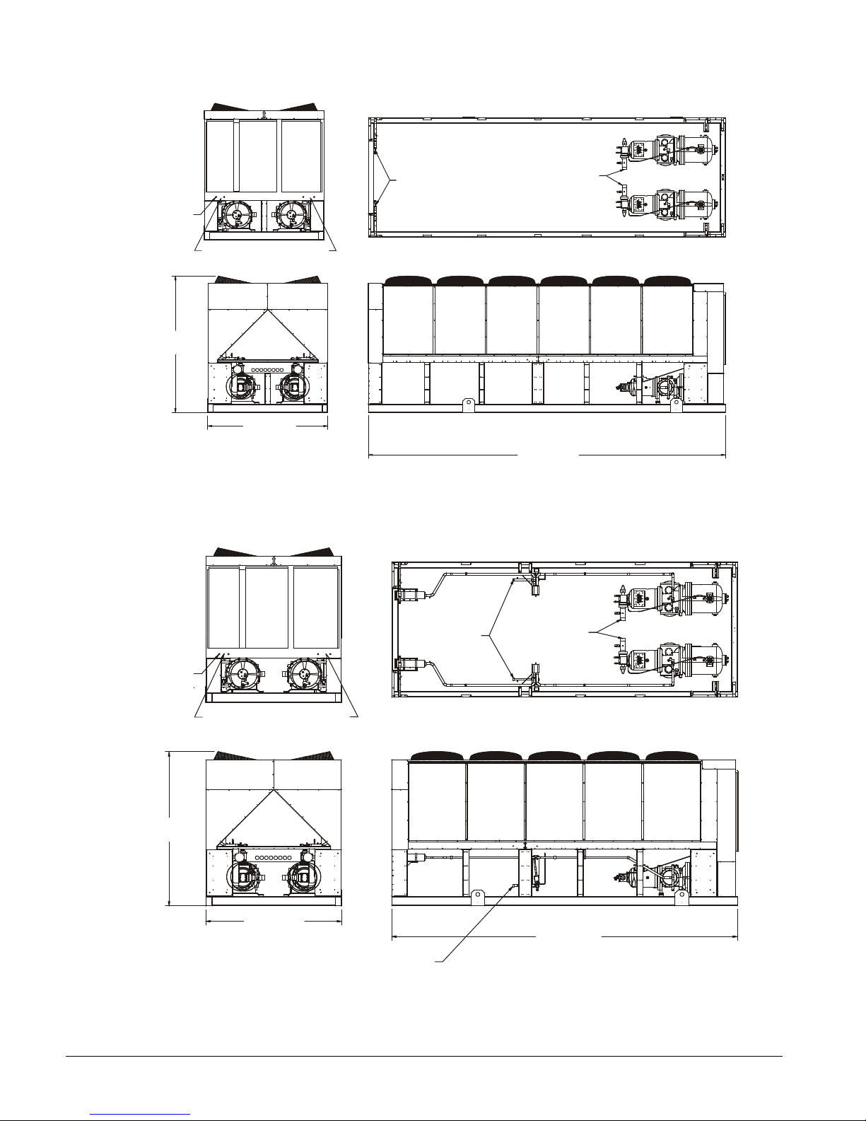
Figure 29, AGS 165CM/B – AGS 175CM/B (with Remote Evaporator)
330712801D030A
AGS-C-165-175
263.0 (6680.2)
SUCTION
(3.12 O.D.)
330712801D020C
AGS-C-180-190
224.8 (5709.9)
LIQUID
SUCTION
0.875
KNOCK OUT
( QTY 4 TOTAL)
100.4
(2550.2)
FIELD CONTROL
(2) CONNECTIONS
88.5 (2247.9)
(2) POWER
ENTRY
LIQUID
CONNECTION
( 1.38 O.D.)
CONNECTION
Figure 30, AGS 180CM/B - AGS 190CM/B (with Remote Evaporator)
0.875
KNOCK OUT
( QTY 4 TOTAL)
100.4
(2550.2)
FIELD CONTROL
(2) CONNECTIONS
88.5 (2247.9)
(2) POWER
ENTRY
LIQUID CONNECTIONS
CONNECTION
( 1.38 O.D.)
CONNECTION
(3.62 O.D.)
52
IMM AGS-2
Page 53

0.875
330712801D030C
AGS-C-195-210
263.0 (6680.2)
LIQUID CONNECTION
SUCTION
KNOCK OUT
( QTY 4 TOTAL)
Figure 31, AGS 195CM/B - AGS 210CM/B (with Remote Evaporator)
CONNECTION
( 1.38 O.D.)
(3.62 O.D.)
100.4
(2550.2)
FIELD CONTROL
(2) CONNECTIONS
88.5 (2247.9)
(2) POWER
ENTRY
LIQUID CONNECTIONS
IMM AGS-2
53
Page 54

Evaporators
EVAP. - AGS 120C-140C
8.8
(223.5)
68.0 (1727.2)
06.00 SCH 40 PIPE
72.3 (1836.4)
85.6 (2174.2)
18.2
(462.3)
92.2 (2341.9)
1.6
2.8 (71.1)
HEATER
11.9
90°
AGS 160C
68.0 (1727.2)
(508.0)
8.8
(223.5)
1/2" NPTF
3000# HALF CPLG.
08.00 SCH 40 PIPE
VICTAULIC GROOVED
70.3 (1786.0)
85.6 (2174.2)
22.5
(572.0)
92.9 (2359.7)
HEATER
13.9 (353.1)
90°
SUCTION
Figure 32, Evaporator for AGS 120C - 140C
2.6 (66.0)
01.625 IDS.
FLANGE
(QTY. 2)
12.4
(315.0)
(302.3)
3.0
(76.2)
MTG.
DWG. 330645800
3.0
(76.2)
12.4
(315.0)
2.6 (66.0)
04.125 IDS.
FLANGE
(QTY. 2)
HEATER
LEADS
21.7
(551.2)
QTY.4
LIQUID
(40.6)
16.0
(406.4)
0.69 HOLES
3.9 (99.1)
OUTLET
VICTAULIC
GROOVED
(QTY. 2)
1/4" NPTF
(QTY. 2)
1/2" NPTF
(QTY. 2)
1/2" NPTF
3000# HALF CPLG.
(QTY. 2)
INLET
LEADS
SUCTION
Figure 33, Evaporator for AGS 160C, AGS 125C - 135C
3.7
3.0 (76.2)
01.625 IDS.
FLANGE
(QTY. 2)
12.4
(315.0)
(94.0)
MTG.
DWG. 330645900
EVAP - AGS 125C-135C
12.4
(315.0)
3.0 (76.2)
04.125 IDS.
FLANGE
(QTY. 2)
HEATER
LEADS
23.7
(601.9)
LIQUID
3.9 (99.1)
1.6 (40.6)
20.0
0.69 HOLES
QTY.4
(QTY 2)
OUTLET
1/4" NPTF
(QTY. 2)
1/2" NPTF
(QTY. 2)
LEADS
4.7 (119.4)
(QTY. 2)
INLET
54
IMM AGS-2
Page 55

Figure 34, Evaporator for AGS 145C
EVAP - AGS 145C
8.8
(223.5)
90.6 (2301.2)
06.00 SCH 40 PIPE
VICTAULIC GROOVED
QTY.4
95.0 (2413.0)
18.2
(462.3)
2.8 (71.1)
1.6
HEATER
11.9
90°
SUCTION
AGS 170C-210C
90.6 (2301.2)
(508.0)
8.8
(223.5)
08.00 SCH 40 PIPE
VICTAULIC GROOVED
22.5
(572.0)
4.7 (119.4)
1.6
1/2" NPTF
1/4" NPTF
HEATER
90°
SUCTION
2.6 (66.0)
01.625 IDS.
FLANGE
(QTY. 2)
12.4
(315.0)
(48.3)
3.0
(76.2)
MTG.
DWG. 330646000
3.0 (76.2)
12.4
(315.0)
2.6 (66.0)
04.125 IDS.
FLANGE
(QTY. 2)
LIQUID
HEATER
LEADS.
21.7
(5512)
0.69 HOLES
3.9 (99.1)
(40.6)
16.0
(406.4)
OUTLET
(QTY. 2)
108.3 (2750.8)
114.9 (2918.5)
1/4" NPTF
(QTY. 2)
1/2" NPTF
(QTY. 2)
1/2" NPTF
3000# HALF CPLG.
(QTY. 2)
LEADS.
INLET
3.0 (76.2)
01.625 IDS.
FLANGE
(QTY. 2)
12.4
(315.0)
Figure 35, Evaporator for AGS 165C - 195C, AGS 170C - 210C
13.9 (353.1)
3.7
(93.9)
330646100
EVAP - AGS 165C-195C
3.7 (93.9)
(315.0)
MTG.
3.0 (76.2)
12.4
HEATER
LEADS
04.125 IDS.
FLANGE
(QTY. 2)
23.7
(601.9)
QTY.4
LIQUID
(40.6)
0.69 HOLES
3.9 (99.1)
OUTLET
QTY. 2
20.0
92.9 (2359.7)
108.3 (2750.8)
115.6 (2936.2)
(QTY. 2)
(QTY. 2)
1/2" NPTF
3000# HALF CPLG.
(QTY. 2)
INLET
LEADS
IMM AGS-2
55
Page 56

Lifting and Mounting Dimensions and Weights, Remote Evaporator
" G "
Figure 36, Mounting and Lifting Dimensions
" E "
" F "
" D "
" C "
M4M2
C/G
CONTROL BOX
44.00
L3L2
M6
M1 M3 M5
" A "
L1
" B "
L4
3307127-00-04
AGS
MODEL
120
125
130
135
140
145
160
165
170
175
180
190
195
210
A B C D E F G
36.00 136.60 12.00 57.30 174.60 61.36 186.60
36.00 168.85 12.00 69.25 212.80 74.80 224.80
36.00 136.60 12.00 57.30 174.60 61.36 186.60
36.00 168.85 12.00 69.25 212.80 74.80 224.80
36.00 136.60 12.00 57.30 174.60 61.36 186.60
36.00 168.85 12.00 69.25 212.80 74.80 224.80
36.00 136.60 12.00 57.30 174.60 61.36 186.60
36.00 189.00 12.00 84.00 251.00 86.83 263.00
36.00 168.85 12.00 69.25 212.80 74.80 224.80
36.00 189.00 12.00 84.00 251.00 86.83 263.00
36.00 168.85 12.00 69.25 212.80 74.80 224.80
36.00 168.85 12.00 69.25 212.80 74.80 224.80
36.00 188.77 12.00 84.00 251.00 86.83 263.00
36.00 188.77 12.00 84.00 251.00 86.83 263.00
NOTES:
1. Center of gravity (f) is calculated from shipping weight.
2. Dimensions in inches.
DIMENSIONS IN INCHES
56
IMM AGS-2
Page 57

Table 31, Lifting and Mounting Weights, Aluminum Fins (Remote Evaporator)
AGS
MODEL
120
125
130
135
140
145
160
165
170
175
180
190
195
210
NOTE: Refer to Figure 36.
Lifting Weights Mounting Weights
L1 & L2 L3 & L4 M1 & M2 M3 & M4 M5 & M6
lbs. kg lbs. kg lbs. kg lbs. kg lbs. kg lbs. kg
3029 1375 1021 464 1747 793 1488 676 815 370 8100 8100
3169 1439 1307 593 1910 867 1632 741 935 424 8952 8952
3029 1375 1021 464 1747 793 1488 676 815 370 8100 8100
3169 1439 1307 593 1910 867 1632 741 935 424 8952 8952
3029 1375 1021 464 1747 793 1488 676 815 370 8100 8100
3169 1439 1307 593 1910 867 1632 741 935 424 8952 8952
3029 1375 1021 464 1747 793 1488 676 815 370 8100 8100
3196 1451 1590 722 2071 940 1741 790 974 442 9571 9571
3169 1439 1307 593 1910 867 1632 741 935 424 8952 8952
3196 1451 1590 722 2071 940 1741 790 974 442 9571 9571
3169 1439 1307 593 1910 867 1632 741 935 424 8952 8952
3169 1439 1307 593 1910 867 1632 741 935 424 8952 8952
3196 1451 1590 722 2071 940 1741 790 974 442 9571 9571
3196 1451 1590 722 2071 940 1741 790 974 442 9571 9571
Operating &
Shipping
Weights
Table 32, Lifting and Mounting Weights, Copper Fins (Remote Evaporator)
Operating &
Shipping
Weights
AGS
MODEL
120
125
130
135
140
145
160
165
170
175
180
190
195
210
Lifting Weights Mounting Weights
L1 & L2 L3 & L4 M1 & M2 M3 & M4 M5 & M6
lbs. kg lbs. kg lbs. kg lbs. kg lbs. kg lbs. kg
3348 1520 1340 608 1960 890 1701 772 1028 467 9376 4257
3568 1620 1706 775 2176 988 1898 862 1201 545 10548 4789
3348 1520 1340 608 1960 890 1701 772 1028 467 9376 4257
3568 1620 1706 775 2176 988 1898 862 1201 545 10548 4789
3348 1520 1340 608 1960 890 1701 772 1028 467 9376 4257
3568 1620 1706 775 2176 988 1898 862 1201 545 10548 4789
3348 1520 1340 608 1960 890 1701 772 1028 467 9376 4257
3675 1668 2069 939 2390 1085 2060 935 1293 587 11487 5215
3568 1620 1706 775 2176 988 1898 862 1201 545 10548 4789
3675 1668 2069 939 2390 1085 2060 935 1293 587 11487 5215
3568 1620 1706 775 2176 988 1898 862 1201 545 10548 4789
3568 1620 1706 775 2176 988 1898 862 1201 545 10548 4789
3675 1668 2069 939 2390 1085 2060 935 1293 587 11487 5215
3675 1668 2069 939 2390 1085 2060 935 1293 587 11487 5215
NOTE: Refer to Figure 36.
IMM AGS-2
57
Page 58
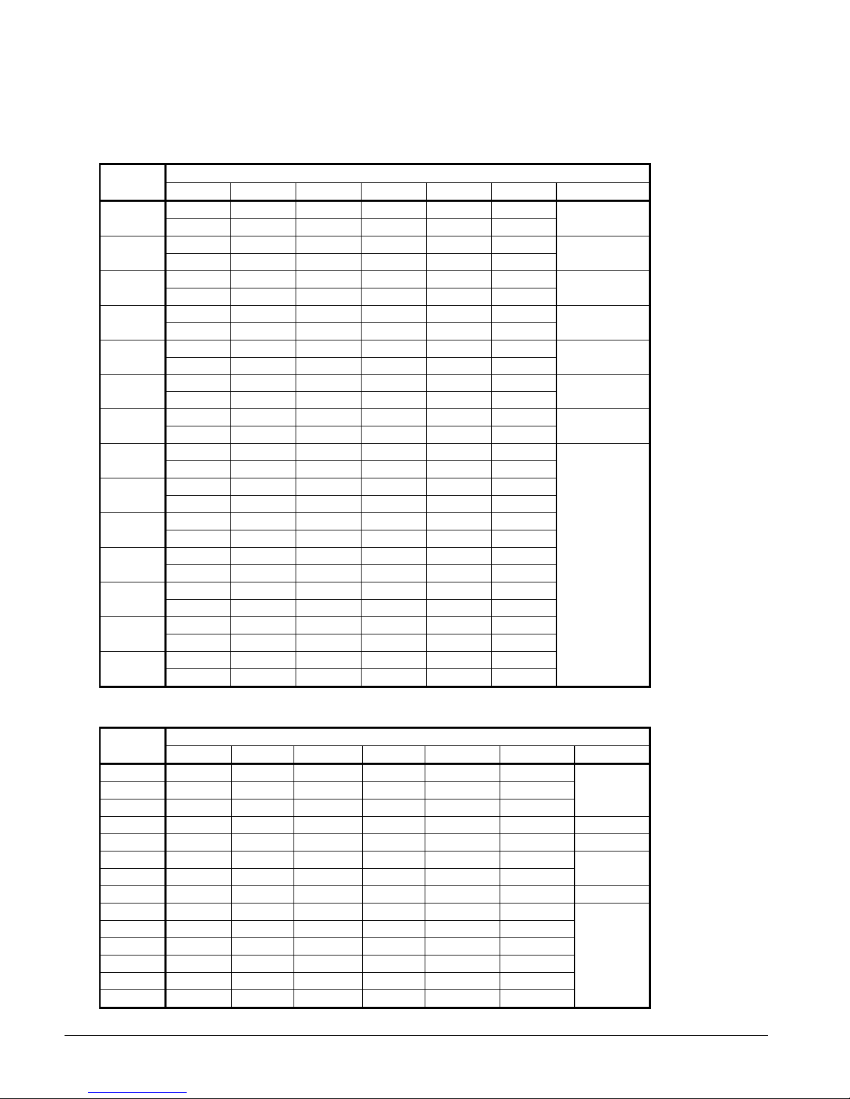
Vibration Isolators, Remote Evaporator
The vibration isolator specific locations and the kit numbers shown on the following two pages are based
on Figure 36 and the weights shown on the previous page.
Table 33, Spring Vibration Isolators, AGS 120C – 210C, Aluminum Fin
AGS
Model
120
125
130
135
140
145
160
165
170
175
180
190
195
210
M1 M2 M3 M4 M5 M6 Kit Number
CP2-28 CP2-28 CP2-27 CP2-27 CP1-28 CP1-28
GREEN GREEN ORANGE ORANGE GREEN GREEN
CP2-31 CP2-31 CP2-28 CP2-28 CP1-31 CP1-31
GRAY GRAY GREEN GREEN WHITE WHITE
CP2-28 CP2-28 CP2-27 CP2-27 CP1-28 CP1-28
GREEN GREEN ORANGE ORANGE GREEN GREEN
CP2-31 CP2-31 CP2-28 CP2-28 CP1-31 CP1-31
GRAY GRAY GREEN GREEN WHITE WHITE
CP2-28 CP2-28 CP2-27 CP2-27 CP1-28 CP1-28
GREEN GREEN ORANGE ORANGE GREEN GREEN
CP2-31 CP2-31 CP2-28 CP2-28 CP1-31 CP1-31
GRAY GRAY GREEN GREEN WHITE WHITE
CP2-28 CP2-28 CP2-27 CP2-27 CP1-28 CP1-28
GREEN GREEN ORANGE ORANGE GREEN GREEN
CP2-31 CP2-31 CP2-28 CP2-28 CP1-31 CP1-31
GRAY GRAY GREEN GREEN WHITE WHITE
CP2-31 CP2-31 CP2-28 CP2-28 CP1-31 CP1-31
GRAY GRAY GREEN GREEN WHITE WHITE
CP2-31 CP2-31 CP2-28 CP2-28 CP1-31 CP1-31
GRAY GRAY GREEN GREEN WHITE WHITE
CP2-31 CP2-31 CP2-28 CP2-28 CP1-31 CP1-31
GRAY GRAY GREEN GREEN WHITE WHITE
CP2-31 CP2-31 CP2-28 CP2-28 CP1-31 CP1-31
GRAY GRAY GREEN GREEN WHITE WHITE
CP2-31 CP2-31 CP2-28 CP2-28 CP1-31 CP1-31
GRAY GRAY GREEN GREEN WHITE WHITE
CP2-31 CP2-31 CP2-28 CP2-28 CP1-31 CP1-31
GRAY GRAY GREEN GREEN WHITE WHITE
Mounting Location
330904121
330904122
330904121
330904122
330904121
330904122
330904121
330904122
Table 34, Neoprene-in-Shear Isolators, AGS 120C – 210C, Aluminum Fin
AGS
Model
120
125
130
135
140
145
160
165
170
175
180
190
195
210
58
IMM AGS-2
M1 M2 M3 M4 M5 M6 Kit Number
RP-4, RED RP-4, RED RP-4, RED RP-4, RED RP-4, BLACK RP-4, BLACK
RP-4, RED RP-4, RED RP-4, RED RP-4, RED RP-4, BLACK RP-4, BLACK
RP-4, RED RP-4, RED RP-4, RED RP-4, RED RP-4, BLACK RP-4, BLACK
RP-4, RED RP-4, RED RP-4, RED RP-4, RED RP-4, RED RP-4, RED 330904112
RP-4, RED RP-4, RED RP-4, RED RP-4, RED RP-4, BLACK RP-4, BLACK 330904111
RP-4, RED RP-4, RED RP-4, RED RP-4, RED RP-4, RED RP-4, RED
RP-4, RED RP-4, RED RP-4, RED RP-4, RED RP-4, RED RP-4, RED
RP-4, GRN RP-4, GRN RP-4, RED RP-4, RED RP-4, BLACK RP-4, BLACK 330904131
RP-4, RED RP-4, RED RP-4, RED RP-4, RED RP-4, RED RP-4, RED
RP-4, RED RP-4, RED RP-4, RED RP-4, RED RP-4, RED RP-4, RED
RP-4, RED RP-4, RED RP-4, RED RP-4, RED RP-4, RED RP-4, RED
RP-4, RED RP-4, RED RP-4, RED RP-4, RED RP-4, RED RP-4, RED
RP-4, RED RP-4, RED RP-4, RED RP-4, RED RP-4, RED RP-4, RED
RP-4, RED RP-4, RED RP-4, RED RP-4, RED RP-4, RED RP-4, RED
Mounti ng Location ( See Footprint D ra wings, page 13)
330904111
330904112
330904112
Page 59

Table 35, Spring Vibration Isolators, AGS 120C – 210C, Copper Fin (Remote Evaporator)
AGS
Model
120
125
130
135
140
145
160
165
170
175
180
190
195
210
M1 M2 M3 M4 M5 M6 Kit Number
CP2-31 CP2-31 CP2-28 CP2-28 CP1-31 CP1-31
GRAY GRAY GREEN GREEN WHITE WHITE
CP2-31 CP2-31 CP2-31 CP2-31 CP2-31 CP2-31
GRAY GRAY GRAY GRAY GRAY GRAY
CP2-31 CP2-31 CP2-28 CP2-28 CP1-31 CP1-31
GRAY GRAY GREEN GREEN WHITE WHITE
CP2-31 CP2-31 CP2-31 CP2-31 CP2-31 CP2-31
GRAY GRAY GRAY GRAY GRAY GRAY
CP2-31 CP2-31 CP2-28 CP2-28 CP1-31 CP1-31
GRAY GRAY GREEN GREEN WHITE WHITE
CP2-31 CP2-31 CP2-31 CP2-31 CP2-31 CP2-31
GRAY GRAY GRAY GRAY GRAY GRAY
CP2-31 CP2-31 CP2-28 CP2-28 CP1-31 CP1-31
GRAY GRAY GREEN GREEN WHITE WHITE
CP2-32 CP2-32 CP2-31 CP2-31 CP2-31 CP2-31
WHITE WHITE GRAY GRAY GRAY GRAY
CP2-31 CP2-31 CP2-31 CP2-31 CP2-31 CP2-31
GRAY GRAY GRAY GRAY GRAY GRAY
CP2-32 CP2-32 CP2-31 CP2-31 CP2-31 CP2-31
WHITE WHITE GRAY GRAY GRAY GRAY
CP2-31 CP2-31 CP2-31 CP2-31 CP2-31 CP2-31
GRAY GRAY GRAY GRAY GRAY GRAY
CP2-31 CP2-31 CP2-31 CP2-31 CP2-31 CP2-31
GRAY GRAY GRAY GRAY GRAY GRAY
CP2-32 CP2-32 CP2-31 CP2-31 CP2-31 CP2-31
WHITE WHITE GRAY GRAY GRAY GRAY
CP2-32 CP2-32 CP2-31 CP2-31 CP2-31 CP2-31
WHITE WHITE GRAY GRAY GRAY GRAY
Mounting Location
330904122
330904123
330904122
330904123
330904122
330904123
330904122
330904105
330904123
330904105
330904123
330904105
IMM AGS-2
Table 36, Neoprene-in-Shear Isolators, AGS 120C – 210C, Copper Fin
AGS
Model
120
125
130
135
140
145
160
165
170
175
180
190
195
210
M1 M2 M3 M4 M5 M6 Kit Number
RP-4, RED RP-4, RED RP-4, RED RP-4, RED RP-4, BLK RP-4, BLK
RP-4, RED RP-4, RED RP-4, RED RP-4, RED RP-4, BLK RP-4, BLK
RP-4, RED RP-4, RED RP-4, RED RP-4, RED RP-4, RED RP-4, RED
RP-4, RED RP-4, RED RP-4, RED RP-4, RED RP-4, RED RP-4, RED
RP-4, RED RP-4, RED RP-4, RED RP-4, RED RP-4, RED RP-4, RED
RP-4, RED RP-4, RED RP-4, RED RP-4, RED RP-4, RED RP-4, RED
RP-4, RED RP-4, RED RP-4, RED RP-4, RED RP-4, RED RP-4, RED
RP-4, GRN RP-4, GRN RP-4, RED RP-4, RED RP-4, BLK RP-4, BLK 330904131
RP-4, RED RP-4, RED RP-4, RED RP-4, RED RP-4, RED RP-4, RED 330904112
RP-4, GRN RP-4, GRN RP-4, GRN RP-4, GRN RP-4, RED RP-4, RED 330904113
RP-4, RED RP-4, RED RP-4, RED RP-4, RED RP-4, RED RP-4, RED
RP-4, RED RP-4, RED RP-4, RED RP-4, RED RP-4, RED RP-4, RED
RP-4, GRN RP-4, GRN RP-4, GRN RP-4, GRN RP-4, RED RP-4, RED
RP-4, GRN RP-4, GRN RP-4, GRN RP-4, GRN RP-4, RED RP-4, RED
Mounti ng Location ( See Footprint D ra wing, page 13)
330904111
330904112
330904112
330904113
59
Page 60

Physical Data, Standard Efficiency
Table 37, Physical Data, AGS 120C – AGS 140C (Remote Evaporator)
DATA
BASIC DATA
Unit Operating Charge lbs (kg), Note 1 131 (59) 131 (59) 131 (59) 131 (59) 131 (59) 131 (59)
Cabinet Dimensions
L x W x H, in. (mm)
Outdoor Unit Operating Weight, lbs. (kg) 8100 (36770 8952 (4064) 8100 (36770
Outdoor Unit Shipping Weight, lbs (kg) 8100 (36770 8952 (4064) 8100 (36770
Add for Copper Fins, lbs (kg) 1276 (579) 1596 (725) 1276 (579)
COMPRESSORS, SCREW, SEMI-HERMETIC
Nominal Capacity, tons (kW) 60 (211) 60 (211) 60 (211) 70 (246) 70 (246) 70 (246)
CONDENSERS, HIGH EFFICIENCY FIN AND TUBE TYPE WITH INTEGRAL SUBCOOLER
Pumpdown Capacity, lbs (kg) 197 (89) 197 (89) 197 (89) 197 (89) 164 (74) 164 (74)
CONDENSER FANS, DIRECT DRIVE PROPELLER TYPE
No. of Fans – 30 in. Fan Dia. 8 8 8
No. of Motors -- hp (kW) 8 2 (1.5) 8 2 (1.5) 8 2 (1.5)
Fan & Motor RPM, 60Hz 1140 1140 1140
60 Hz Fan Tip Speed, fpm (m/s) 8950 (4224) 8950 (4224) 8950 (4224)
60 Hz Total Unit Airflow, cfm (l/s) 86900 (41020) 86900 (41020) 86900 (41020)
REMOTE EVAPORATOR, DIRECT EXPANSION SHELL AND TUBE
Shell Dia.-Tube Length
in.(mm) - in. (mm)
Operating Weight, lbs (kg) 1282 (562) 1282 (562) 1282 (562)
Shipping Weight, lbs (kg) 875 (397) 875 (397) 875 (397)
Evaporator R-134a Charge lbs (kg) 1.95 (0.9) 1.95 (0.9) 1.95 (0.9) 1.95 (0.9) 1.95 (0.9) 1.95 (0.9)
Water Volume, gallons (liters) 49 (185) 49 (185) 49 (185)
Max. Water Pressure, psi (kPa) 152 (1048) 152 (1048) 152 (1048)
Max. Refrigerant Press., psi (kPa) 352 (2427) 352 (2427) 352 (2427)
120C 130C 140C
Ckt 1 Ckt 2 Ckt 1 Ckt 2 Ckt 1 Ckt 2
187 x 89 x 101
4750 x 2261 x 2565
15.5 x 82.4
(394 x 2093)
NOTE: Charge quantity does not include field piping.
AGS MODEL NUMBER
187 x 89 x 101
4750 x 2261 x 2565
15.5 x 82.4
(394 x 2093)
187 x 89 x 101
4750 x 2261 x 2565
15.5 x 82.4
(394 x 2093)
Table 38, Physical Data, AGS 160C – AGS 180C (Remote Evaporator)
AGS MODEL NUMBER
DATA 160C 170C 180C
Ckt. 1 Ckt. 2 Ckt. 1 Ckt. 2 Ckt. 1 Ckt. 2
BASIC DATA
Unit Operating Charge, lbs (kg) 131 (59) 131 (59) 159 (72) 159 (72) 171 (78) 171 (78)
Cabinet Dim., L x W x H, in. (mm)
Outdoor Unit Operating Wt, lbs. (kg) 8100 (36770 8952 (4064 8952 (4064
Outdoor Unit Shipping Wt, lbs (kg) 8100 (36770 8952 (4064 8952 (4064
Add for Copper Fins, lbs (kg) 1276 (579) 1596 (725) 1596 (725)
COMPRESSORS, SCREW, SEMI-HERMETIC
Nominal Capacity, tons (kW) 70 (246) 85 (299) 85 (299) 85 (299) 95 (334) 95 (334)
CONDENSERS, HIGH EFFICIENCY FIN AND TUBE TYPE WITH INTEGRAL SUBCOOLER
Pumpdown Capacity, lbs (kg) 197 (89) 197 (89) 247 (112) 247 (112) 247 (112) 247 (112)
CONDENSER FANS, DIRECT DRIVE PROPELLER TYPE
No. of Fans; Fan Dia., in. (mm) 8 10 10
No. of Motors – hp (kW) 8 2 (1.5) 10 2 (1.5) 10 2 (1.5)
Fan & Motor RPM, 50Hz 1140 1140 1140
60 Hz Fan Tip Speed, fpm 8950 (4224) 8950 (4224) 8950 (4224)
m60 Hz Total Unit Airflow, cfm (l/s) 86900 (41020) 108630 (51280) 108630 (51280)
REMOTE EVAPORATOR, DIRECT EXPANSION SHELL AND TUBE
Shell Dia.,Tube Length in.(mm)
Operating Weight, lbs (kg) 1916 (870) 2283 (1037) 2283 (1037)
Shipping Weight, lbs (kg) 1224 (556) 1400 (636) 1400 (636)
Evaporator R-134a Charge lbs (kg) 2.53 (1.1) 2.53 (1.1) 3.16 (1.4) 3.16 (1.4) 3.16 (1.4) 3.16 (1.4)
Water Volume, gallons (liters) 83 (314) 106 (401) 106 (401)
Max. Water Pressure, psi (kPa) 152 (1048) 152 (1048) 152 (1048)
Max. Refrigerant Press., psi (kPa) 352 (2427) 352 (2427) 352 (2427)
187 x 89 x 101
4750 x 2261 x 2565
19.4 x 82.4
(493 x 2093)
225 x 89 x 101
5715 x 2261 x 2565
19.4 x 105.1
(493 x 2670)
225 x 89 x 101
5715 x 2261 x 2565
19.4 x 105.1
(493 x 2670)
60
IMM AGS-2
Page 61

Table 39, Physical Data, AGS 190C – AGS 210C (Remote Evaporator)
DATA
BASIC DATA
Unit Operating Charge lbs (kg) 172 (78) 172 (78) 201 (91) 201 (91)
Cabinet Dimensions
L x W x H, in. (mm)
Unit Shipping Weight, lbs (kg) 8952 (4064) 9571 (4345
Unit Operating Weight, lbs. (kg) 8952 (4064) 9571 (4345
Add for Copper Fins, lbs (kg 1596 (725) 1916 (870)
COMPRESSORS, SCREW, SEMI-HERMETIC
Nominal Capacity, tons (kW) 95 (334) 95 (334) 95 (334) 95 (334)
CONDENSERS, HIGH EFFICIENCY FIN AND TUBE TYPE WITH INTEGRAL SUBCOOLER
Pumpdown Capacity, lbs (kg) 247 (112) 247 (112) 296 (134) 296 (134)
CONDENSER FANS, DIRECT DRIVE PROPELLER TYPE
No. of Fans -- Fan Dia., in. (mm) 10 12
No. of Motors -- hp (kW) 10 2 (1.5) 12 2.5 (1.9)
Fan & Motor RPM, 50Hz 1140 1140
60 Hz Fan Tip Speed, fpm (m/s) 8950 (4224) 8950 (4224)
60 Hz Total Unit Airflow, cfm (l/s) 108630 (51280) 130360 (61530)
REMOTE EVAPORATOR, DIRECT EXPANSION SHELL AND TUBE
Shell Dia.-Tube Length
in.(mm) - in. (mm)
Operating Weight, lbs (kg) 2281 (1036) 2281 (1036)
Shipping Weight, lbs (kg) 1437 (652) 1437 (652)
Evaporator R-134a Charge lbs (kg) 3.63 (1.6) 3.63 (1.6) 3.63 (1.6) 3.63 (1.6)
Water Volume, gallons (liters) 106 (401) 104 (392)
Max. Water Pressure, psi (kPa) 152 (1048) 152 (1048)
Max. Refrigerant Press., psi (kPa) 352 (2427) 352 (2427)
AGS 190C AGS 210C
Ckt 1 Ckt 2 Ckt 1 Ckt 2
225 x 89 x 101
5715 x 2261 x 2565
19.4 x 105.1
(493 x 2670)
263 x 89 x 101
6680 x 2261 x 2565
19.4 x 105.1
(493 x 2670)
Physical Data, High Efficiency
Table 40, Physical Data, AGS 125C – AGS 145C (Remote Evaporator)
DATA
BASIC DATA
Unit Operating Charge lbs (kg) 159 (72) 159 (72) 159 (72) 159 (72) 159 (72) 159 (72)
Cabinet Dimensions
L x W x H, in. (mm)
Unit Operating Weight, lbs. (kg) 8952 (4064 8952 (4064 8952 (4064
Unit Shipping Weight, lbs (kg) 8952 (4064 8952 (4064 8952 (4064
Add for Copper Fins, lbs (kg 1596 (725) 1596 (725) 1596 (725)
COMPRESSORS, SCREW, SEMI-HERMETIC
Nominal Capacity, tons (kW) 60 (211) 60 (211) 60 (211) 70 (246) 70 (246) 70 (246)
CONDENSERS, HIGH EFFICIENCY FIN AND TUBE TYPE WITH INTEGRAL SUBCOOLER
Pumpdown Capacity, lbs (kg) 247 (112) 247 (112) 247 (112) 247 (112) 247 (112) 247 (112)
CONDENSER FANS, DIRECT DRIVE PROPELLER TYPE
No. of Fans -- Fan Dia., in. (mm) 10, 30 (762) 10, 30 (762) 10, 30 (762)
No. of Motors -- hp (kW) 10 2 (1.5) 10 2 (1.5) 10 2 (1.5)
Fan & Motor RPM, 60Hz 1140 1140 1140
60 Hz Fan Tip Speed, fpm (m/s) 8950 (4224) 8950 (4224) 8950 (4224)
60 Hz Total Unit Airflow, cfm (l/s) 108630 (51280) 108630 (51280) 108630 (51280)
REMOTE EVAPORATOR, DIRECT EXPANSION SHELL AND TUBE
Shell Dia.-Tube Length
in.(mm) - in. (mm)
Operating Weight, lbs (kg) 1916 (870) 1916 (870) 1525 (692)
Shipping Weight, lbs (kg) 1224 (556) 1224 (556) 1005 (456)
Evaporator R-134a Charge lbs (kg) 2.53 (1.1) 2.53 (1.1) 2.53 (1.1) 2.53 (1.1) 2.44 (1.1) 2.44 (1.1)
Water Volume, gallons (liters) 83 (314) 83 (314) 62 (236)
Max. Water Pressure, psi (kPa) 152 (1048) 152 (1048) 152 (1048)
Max. Refrigerant Press., psi (kPa) 352 (2427) 352 (2427) 352 (2427)
125C 135C 145C
Ckt 1 Ckt 2 Ckt 1 Ckt 2 Ckt 1 Ckt 2
225 x 89 x 101
5715 x 2261 x 2565
19.4 x 82.4
(493 x 2093)
225 x 89 x 101
5715 x 2261 x 2565
19.4 x 82.4
(493 x 2093)
225 x 89 x 101
5715 x 2261 x 2565
19.4 x 105.1
(493 x 2670)
IMM AGS-2
61
Page 62

Table 41, Physical Data, AGS 165C – AGS 195C (Remote Evaporator)
DATA
BASIC DATA
Unit Operating Charge lbs (kg) 186 (84) 186 (84) 186 (84) 186 (84) 201 (91) 201 (91)
Cabinet Dimensions
L x W x H, in. (mm)
Unit Operating Weight, lbs. (kg) 9571 (4345) 9571 (4345) 9571 (4345)
Unit Shipping Weight, lbs (kg) 9571 (4345) 9571 (4345) 9571 (4345)
Add for Copper Fins, lbs (kg 1916 (879) 1916 (879) 1916 (879)
COMPRESSORS, SCREW, SEMI-HERMETIC
Nominal Capacity, tons (kW) 70 (246) 85 (299) 85 (299) 85 (299) 95 (334) 95 (334)
CONDENSERS, HIGH EFFICIENCY FIN AND TUBE TYPE WITH INTEGRAL SUBCOOLER
Pumpdown Capacity, lbs (kg) 296 (134) 296 (134) 296 (134) 296 (134) 296 (134) 296 (134)
CONDENSER FANS, DIRECT DRIVE PROPELLER TYPE
No. of Fans -- Fan Dia., in. (mm) 12 12 12
No. of Motors -- hp (kW) 12 2 (1.5) 12 2 (1.5) 12 2 (1.5)
Fan & Motor RPM, 60Hz 1140 1140 1140
60 Hz Fan Tip Speed, fpm (m/s) 8950 (4224) 8950 (4224) 8950 (4224)
60 Hz Total Unit Airflow, cfm (l/s) 130360 (61530) 130360 (61530) 130360 (61530)
REMOTE EVAPORATOR, DIRECT EXPANSION SHELL AND TUBE
Shell Dia.-Tube Length
in.(mm) - in. (mm)
Operating Weight, lbs (kg) 2283 (1037) 2283 (1037) 2281 (1036)
Shipping Weight, lbs (kg) 1400 (636) 1400 (636) 1437 (652)
Evaporator R-134a Charge lbs (kg) 3.16 (1.4) 3.16 (1.4) 3.16 (1.4) 3.16 (1.4) 3.63 (1.6) 3.63 (1.6)
Water Volume, gallons (liters) 106 (401) 106 (401) 106 (401)
Max. Water Pressure, psi (kPa) 152 (1048) 152 (1048) 152 (1048)
Max. Refrigerant Press., psi (kPa) 352 (2427) 352 (2427) 352 (2427)
165C 175C 195C
Ckt 1 Ckt 2 Ckt 1 Ckt 2 Ckt 1 Ckt 2
263 x 89 x 101
6680 x 2261 x 2565
19.4 x 105.1
(493 x 2670)
AGS MODEL NUMBER
263 x 89 x 101
6680 x 2261 x 2565
19.4 x 105.1
(493 x 2670)
263 x 89 x 101
6680 x 2261 x 2565
19.4 x 105.1
(493 x 2670)
62
IMM AGS-2
Page 63

Solid State Starters
Solid state starters are standard on all AGS units. A solid state starter uses a siliconcontrolled rectifier (SCR) power section to allow a motor to be brought to full speed with a
reduced initial voltage that increases to full line voltage over a given time. The McQuay
motor starter, custom designed for this specific application, is microprocessor controlled.
Along with this starting technique, the motor starter also provides protection for the motor
and monitors its load conditions.
The starter offers:
• Solid state design.
• Closed-loop motor current control.
• Programmable motor protection.
• Programmable operating parameters.
• Programmable metering options.
The three-phase starter contains a six-SCR power section with two SCRs per phase
connected in inverse parallel. This power section is capable of providing maximum torque
per amp throughout the motor’s speed-torque curve with minimal motor and starter heating.
At the same time, the starter continually monitors the amount of current being delivered to
the motor, thus helping to protect the motor from overheating or drawing excessive current.
The starter will automatically stop the motor if the line-to-line current is not within
acceptable ranges, or if the current is lost in a line. The motor current scaling is set
according to the motor size and the specific application. The starter circuitry is contained
on a single printed circuit board, which contains all the logic and SCR gate drive circuitry.
Operating messages are displayed on a three-character LED display located in the unit
control panel. The LED display on the control card displays:
• Operating messages that indicate the status of the motor and/or starter.
• Operating parameters that are programmed into the starter.
• Fault codes that indicate a problem with the motor application or starter.
Operating Messages
Possible operating messages are as follows:
Message Meaning
noL Line voltage is not present.
rdy Line voltage is present and starter is ready.
acc Motor is accelerating after a start command has been received.
uts The motor has achieved full speed.
run Motor is operating at full speed, and ramp time has expired.
dCL A Stop command was received and the motor is decelerating with the set
deceleration profile.
IMM AGS-2
63
Page 64
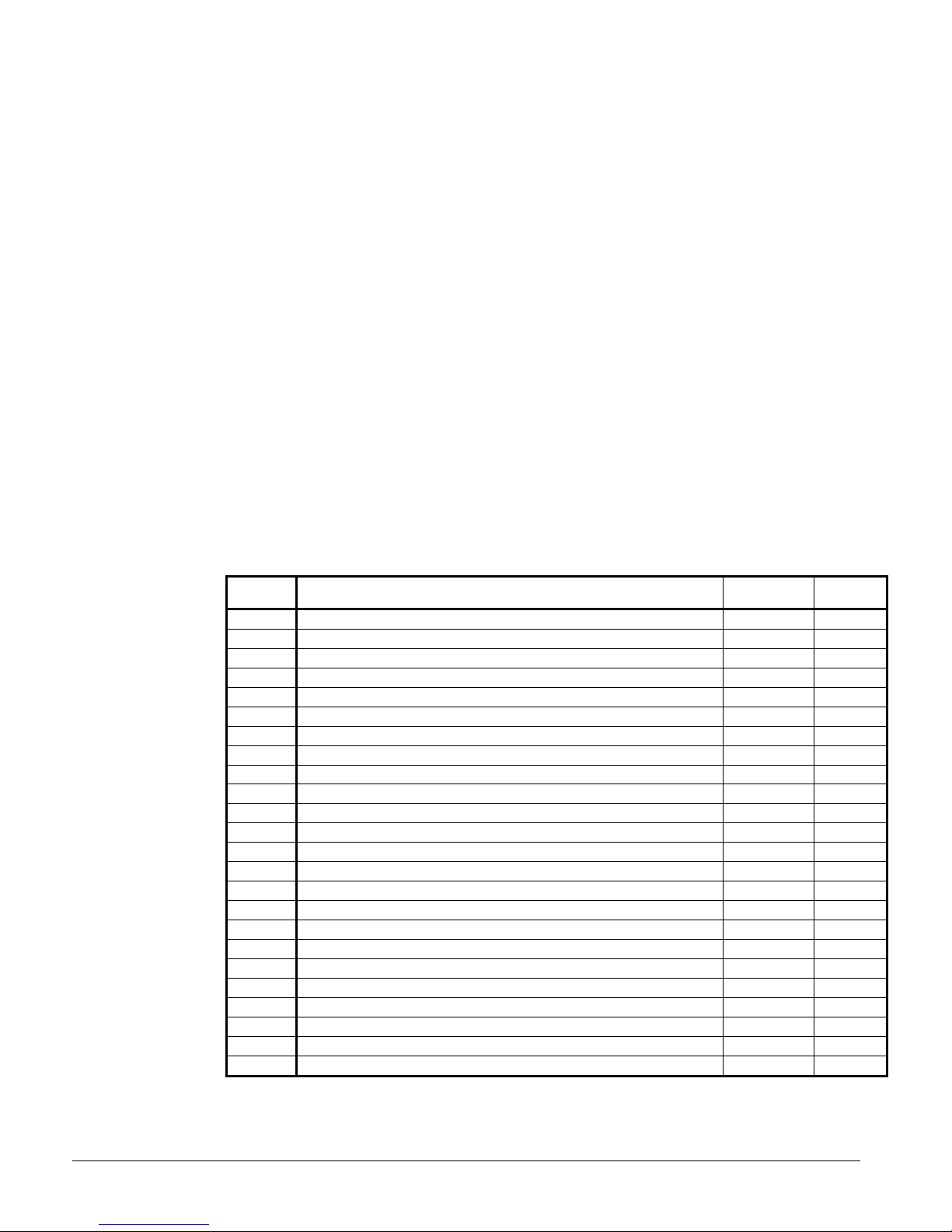
OL OL will alternately blink with the normal display on the LED display when
motor thermal overload content has reached 90% to 99% of its capacity.
OLL The motor thermal overload content has reached 100%, and the motor has
stopped. The motor cannot be restarted until the overloaded motor has
cooled and OLt is displayed.
OLt The motor thermal overload content has been reduced to 60% or less, and
the motor can be restarted.
ena Passcode protection is enabled.
dis Passcode is disabled.
oxx xx = overload thermal content in percentage. Press the Down button to
toggle to this display.
cxx xx = pending fault.
no Attempted to change a passcode protected parameter without proper
security.
… Three decimal places blink when remote display is active.
Fxx xx Fault Code
Table 42, Fault Codes
Number Des cr iption
00 No Fa ul t -- --
01 UTS Time L imit Expired Y Y
02 Motor T herm al Overload Trip Y N
10 Pha se Rotation E rror, Not A-B-C N Y
12 Low Line Frequency N Y
13 High Line Frequency N Y
15 Inp ut Power Not Three phase N Y
21 Low Line L1-L2 Vo lt age Y Y
22 Low Line L2-L3 Vo lt age Y Y
23 Low Line L3-L1 Vo lt age Y Y
24 High Li ne L1-L2 Voltage Y Y
25 High Li ne L2-L3 Voltage Y Y
26 High Li ne L3-L1 Voltage Y Y
27 Pha se loss N Y
28 No Li ne Voltage N Y
30 I.O.C. (Inst antaneous Overcurrent) N N
31 Overcurrent Y N
37 Current I mbalance Y Y
38 Ground Fa ul t Y N
39 No Current At Run N Y
40 Shorted/Open SCR N N
47 Stack Prot ec tion Fault N Y
48 Bypas s Contact or F ault (on STOP input) Y N
50 Control Power Low N Y
Continued next page
Controlled
Stop
Auto
Res et
64
IMM AGS-2
Page 65

Number Des cr iption
51 Current S ensor Offse t Error -- N
52 Burden Swit ch Error N N
60 Therm istor T ri p N N
61 Stack OT Swi tch Trip N N
71 Ana lo g Input Trip Y Y
82 Modbus Ti me-out Y Y
94 CPU E rror – Software Fault N N
95 CPU E rror – Parame ter Storage Fault N N
96 CPU E rror – Illegal Instructi on Trap N N
97 CPU E rror – Software W atc hd og Fault N N
98 CPU E rror – Spurious I nterrupt N N N
99 CPU E rror – Program Storage Fault N N
Controlled
Stop
Starter Planned Maintenance
During commissioning:
• Torque all power connections during commissioning. This includes factory-wired
components.
• Check all of the control wiring in the package for loose connections.
During the first month after the starter has been put in operation:
• Re-torque all power connections every two weeks. This includes factory-wired
components.
• Inspect cooling fans (if applicable) after two weeks for proper operation.
After the first month of operation:
• Re-torque all power connections every year.
• Clean any accumulated dust from the starter using a clean source of compressed air.
• Inspect the cooling fans every three months for proper operation.
• Clean or replace any air vent filters on the starter every three months.
Auto
Res et
IMM AGS-2
NOTE: If mechanical vibrations are present at the installation site, inspect the connections
more frequently.
65
Page 66

Figure 37, Trouble Shooting Guide
N
N
N
N
N
N
N
N
N
N
N
N
N
Start
Replace
Fuses
Replace
Circuit
Breaker
Correct
Inline Fault
o
o
o
Fuses OK?
Circuit
Breaker OK?
Yes
In-Line OK?
Yes
Correct Power
Source
Problem
Yes
Low or Missing
1
Phase Order
2
Thermal Trip?
Yes
o
Wiring OK?
Control Card
3
Line?
o
4
Yes
Fault
oYes
5
Yes
o
6
Interlock
Open?
o
7
Yes Yes
Replace
Swap Any
2 Power
Leads
High
Ambient?
Correct and
Wait to Cool
8
o
Yes
Circulation?
9
Bad Air
o
Correct
Interlock
State
Correct
Wiring
o
Does Problem
Still Exist
Yes
Go to Page 39
Correct
Wiring
Return To
Service
o
Return To
Service
Wiring OK?
Yes
Correct and
Wait to Cool
o
7
Motor
Overloaded?
Yes
Lower Motor
Load
66
IMM AGS-2
10
Page 67

e
s
e
s
Yes
Yes
N
o
N
o
N
o
N
o
blem?
ror
Motor
act
a
w
stanc
e
Replace
ControlCard
CheckJumper
s
Parameter
s
andCT
s
DoesProblem
StillExist?
Contact
From Previous Page
11
Current
Imbalance Fault?
Yes
No
Correct Wiring
Replace
Defective SCRs
No
No
7
Wiring Good?
Yes Y
12
Motor
Winding Short?
No
SCRs OK?
Yes Y
All Gate
Pulses Present?
No
Replace
Control Card
Yes
13
14
Yes
Fuses Blown or
Breaker Tripped?
Replace Fuse
or Reset Breaker
Motor Pro
Repai
Replace
Cont
Bensh
For Assi
12
CT Burden
Switches Set
Correctly?
15
IMM AGS-2
Return to
Normal
Operation
McQuay
For Assistance
67
Page 68

FLOW CHART DETAILS:
1. Fuses Determine if power line fuses have been installed, and if
they are operating properly.
2. Circuit Breaker Determine if the circuit breaker is off, or has tripped and
disconnected the line from the starter.
3. Power Line Voltage Verify that line voltage is present, and that it is the correct
voltage.
4. Phase Order Fault If Fault Codes F1 or F2 are displayed on the control card
LED display, exchange any two incoming power line
cable connections.
5. Heat Sink Switch Investigate whether heat sink thermal switch is open.
6. Safety Device Determine if an equipment protection device attached to
the starter is disabling the start command.
7. Wiring Connections Verify that the wiring connections are correct and that the
terminations are tightened.
8. Air Temperature Investigate whether the air temperature surrounding the
heat sink is hot.
9. Air Circulation Determine if the airflow around the heat sink fins is being
restricted, or if a fan has failed.
10. Motor Overload Determine if the motor’s load is too large for the motor
size.
11. Current Imbalance Fault If Fault Codes F23 or F24 are displayed on the control
card LED display, diagnose and correct the cause of the
current imbalance parameter P16.
12. Motor Winding Problem Conducting a megger test of the motor can identify an
internal motor winding problem. NOTE: To avoid
damaging the starter isolate the motor before conducting
the megger test.
WARNING
Hazardous voltages exist at the starter terminals. Lock out and tag all power sources
before making resistance measurements to avoid personal injury or death.
13. SCRs This step can help determine if a problem exists with the
SCRs. Using a multi-meter or similar device, measure the
resistance between:
•
L1 terminal and T1 terminal
•
L2 terminal and T2 terminal
•
L3 terminal and T3 terminal
The resistance should be more than 50k ohms. Measure
the gate resistance between the white and red of each
twisted pair (6 total). The gate resistance should be
between 8 and 50 ohms.
14. Gate Pulses
This step can help to determine if the control card is
functioning properly. Check for gate firing voltage
between 0.3 and 1.5 volts when the card is operating.
15. Motor Current
68
IMM AGS-2
Determine if motor current signal scaling is correct.
Page 69

Solid State Starter Settings
Operating Parameters Settings for Default Value and Settable Range:
Table 43, Starter Settings
No. Operating Parameter Default Range of Setting
P1
P2
P3
P4
P5
P6
P7
P8
P9
P10
P11
P12
P13
P14
P15
P16 Rated RMS Voltage 460
P17
P18
P19
P20
P21
P22
P23
P24
P25
P26
P27
P28
P29
P30
P31
P32
Motor Full Load Amps (FLA) 1A 1 to 9999A
Motor Rated Load Amps (RLA) 1A 1 to 9999A
Motor Service Factor 1.25 1-1.99
Motor Overload Class 10 1-40,Off
Initial Motor Starting Current 225% 50 - 400%
Max. Motor Starting Current 300% 100 – 800%
Motor Ramp Time 7 sec 0 - 300 sec
UTS time 10 sec 1 - 900 sec
Stop Mode Cos Coast/Voltage decel
Deceleration Level 1 40% 0 – 100%
Deceleration Level 2 20% 0 – 50%
Deceleration Time 2 sec 1 – 180 sec
Default Meter Display 0(Status) 0-19
Overcurrent Trip Level 140% Off, 50 to 800%RLA
Overcurrent Trip Time 2 sec Off, .1 – 90 sec
100,110,120,200,208,220,230,24
0,350,380,400,415,440,460,480,
500,525,575,600,660,690,1000
Overvoltage Trip Level 10% Off, 1 – 40% rated volts
Undervoltage Trip Level 10% Off, 1 – 40% rated volts
Over/Under Voltage Delay Time 1 Sec .1-90 Sec
Current Imbalance Trip Level 40% 5 - 40%
Controlled Fault Stop Off Off, On
Auto Fault Reset Delay Time 60 Off, 1 – 120 sec
CT Ratio 2640
Control Source Ter Terminal/Network
Modbus Address 2 1 - 247
Modbus Baud Rate 19.2 Kbps 1.2,2.4,4.8,9.6,19.2 kbps
Modbus Timeout 1 sec Off, 1 – 120 sec
Analog Output Function 1 1 - 11
Analog Output Span 100% 1 – 125%
Analog Output Offset 0% 0 – 99%
Passcode 0-9999
Fault Log Display faults
72,96,144,288,864,2640,2880,57
60,8000,14400,28800
IMM AGS-2
69
Page 70

Component Location
Major Component Location
Figure 38, Unit Cutaway View
Power Panel
Control Panel
Filter-drier (2)
Electronic
Expansion
Valve (2)
Liquid Connection for Remote
Evaporators, Models AGS 120C – 175C
70
IMM AGS-2
Suction Connection for
Remote Evaporators (2)
Chilled Water Inlet
Two-circuit DX Evaporator
Chilled Water Outlet
Page 71

Figure 39, Piping Schematic, One of Two Circuits
SCHRADER
VALVE
SOLENOID
GLASS
EXPANSION
VALVE
WATER IN
WATER OUT
DX EVAPORATOR
SUCTION
SHUT-OFF
SUCTION
SCHRADER
330591001-PACKAGE
LIQUID
TUBING
LIQUID
SHUT-OFF
VALVE
CHARGING
VALVE
AIR
FLOW
SCHRADER
VALVE
AIR
FLOW
FILTER
CONDENSOR
ASSEMBLY
DRIER
VALVE
(HEADER)
DISCHARGE
AIR
FLOW
TUBING
VALVE
SCHRADER
VALVE
RELIEF
VALVE
FRAME 3200
COMPRESSOR
TUBING
RELIEF
VALVE
VALVE
(OPTIONAL)
CHARGING
VALVE
SIGHT
The above diagram illustrates one of the two circuits of an AGS chiller. The evaporator has
two single-pass circuits with water passing over baffles on the shell side.
The vertical and slanted coils on one side of the unit comprise a condensing circuit. Models
AGS 180C through 210C have an external economizer circuit consisting of a brazed-plate
heat exchanger and expansion valve (not shown on the above diagram).
Figure 40, Compressor-mounted Components
Mechanical High
Pressure Cutout Switch
Compressor Relief Valve
Oil Heater
Optical Oil Level Sensor
IMM AGS-2
71
Page 72

Control Transformer
Line
Reactors for
Optional
Fan VFDs
VFD Fuses
Fan Circuit
Breakers
Power Panel
The power panel is located on the front of the unit, to the right of the control panel.
Figure 41, Power Panel Components (Single Point Power)
Cir#2 Circuit Breaker,
Single Point Power Only
Primary Control Power Fuses
Cir#1 Circuit Breaker,
Single Point Power Only
Unit Circuit
Breaker
(Optional)
Cir#2 Fan VFD
(Optional)
Cir#1 Fan VFD
(Optional)
Fan Contactors
Cir#2 Starter
Grounding
Lug
Incoming
Power
Connection
Cir#1 Starter
72
IMM AGS-2
Page 73

Control Panel
The control panel is located on the front of the unit, to the left of the power panel.
Distributed control architecture enhances unit reliability. Each compressor circuit has its own
microprocessor controller so that if one circuit controller is inoperative, the other circuit
controller will still be able to run its compressor and circuit components.
Figure 42, Control Panel Components
T2 T13 T14 T15 T23 T24 T25
T2 24V Unit Controller Transformer
T13, T23 24V Circuit Controller Transformers
T14, T24 24V Compressor Load/Unload Trns.
T15, T25 24V EXV Driver Transformer
Transformers
Unit Controller
Cir#1 Controller
Cir#2 Controller
IMM AGS-2
73
Page 74

Glass
System Maintenance
General
On initial start-up and periodically during operation, it will be necessary to perform certain
routine service checks. Among these are checking the liquid line sight glasses, and the
compressor oil level sight glass. In addition, check the MicroTech II controller temperature
and pressure readings with gauges and thermometers to see that the unit has normal
condensing and suction pressure and superheat and subcooling readings. A recommended
maintenance schedule is located at the end of this section.
A Periodic Maintenance Log is located at the end of this manual. It is suggested that the
log be copied and a report be completed on a regular basis. The log will serve as a useful
tool for a service technician in the event service is required.
Initial start-up date, vibration readings, compressor megger readings and oil analysis
information should be kept for reference base-line data.
Compressor Maintenance
Since the compressor is semi-hermetic, no yearly compressor maintenance is normally
required; however, vibration is an excellent check for proper mechanical operation.
Compressor vibration contributes to a decrease in unit performance and efficiency and
indicates that maintenance is required. It is recommended that the compressor be checked
with a vibration analyzer at, or shortly after, start-up and again on an annual basis. The load
should be maintained as closely as possible to the load of the original test and only one
compressor should be running at a time. The initial vibration analyzer test provides a
benchmark of the compressor and, when performed routinely, can give a warning of
impending problems.
Lubrication
No routine lubrication is required on AGS units. The fan motor bearings are permanently
lubricated. No further lubrication is required. Excessive fan motor bearing noise is an
indication of a potential bearing failure.
Figure 43, Compressor Oil Filter
Compressor oil must be ICI RL68HB, McQuay Part
Number 735030446 in a 1-gallon container. This is
synthetic polyolester oil with anti-wear additives and
is highly hygroscopic. Care must be taken to
minimize exposure of the oil to air when charging oil
into the system.
The oil filter resides in the compressor
Oil
Sight
The top of the oil level should be visible in the sight glass. If the glass is completely filled
with oil at all times, the circuit is overcharged with oil. If only refrigerant is visible in the
glass, the circuit has insufficient oil.
A mechanical oil pressure differential switch is mounted on the unit frame adjacent to each
compressor and will shut down the compressor at a differential pressure greater than 25 psi.
Oil Filter
Housing
housing as shown in Figure 43. Units without a
suction service shutoff valve require pumping down
the circuit in order to change the filter.
74
IMM AGS-2
Page 75

The switch has automatic reset but is locked out by the MicroTech II control, which must be
reset through the software. A gauge can be put across the switch to actually measure the
pressure drop. The normal pressure drop is 5 to 6 psi. Change the filter at 15 psi.
Electrical Terminals
DANGER
Electric equipment can cause electric shock with a risk of severe personal injury or
death. Turn off, lock out and tag all power before continuing with following service.
Panels can have more than one power source.
CAUTION
Periodically check electrical terminals for tightness and tighten as required. Always
use a back-up wrench when tightening electrical terminals.
Condensers
The condensers are air-cooled and constructed of 3/8" (9.5mm) OD internally finned copper
tubes bonded in a staggered pattern into louvered aluminum fins. No maintenance is
ordinarily required except the routine removal of dirt and debris from the outside surface of
the fins. McQuay recommends the use of non-caustic, non-acidic, foaming coil cleaners
available at most air conditioning supply outlets. Flush the coil from the inside out.
WARNING
Use caution when applying coil cleaners. They can contain potentially harmful
chemicals. Wear breathing apparatus and protective clothing. Thoroughly rinse all
surfaces to remove any cleaner residue. Do not damage the fins during cleaning.
If the service technician has reason to believe that the refrigerant circuit contains
noncondensables, recovery of the noncondensables will be required, strictly following
Clean Air Act regulations governing refrigerant discharge to the atmosphere. The service
Schrader valves are located on both vertical coil headers on both sides of the unit at the
control box end of the coil. Access panels are located at the end of the condenser coil
directly behind the control panel. Recover the noncondensables with the unit off, after
shutdown of 15 minutes or longer, to allow air to collect at the top of the coil. Restart and
run the unit for a brief period. If necessary, shut the unit off and repeat the procedure.
Follow accepted environmentally sound practices when removing refrigerant from the unit.
Liquid Line Sight Glass
Observe the refrigerant sight glasses (one per circuit) weekly. A clear glass of liquid
indicates that there is adequate refrigerant charge in the system to provide proper feed
through the expansion valve. Bubbling refrigerant in the liquid line sight glass, during
stable run conditions, may indicate that there can be an electronic expansion valve (EXV)
problem since the EXV regulates liquid subcooling. Refrigerant gas flashing in the sight
glass could also indicate an excessive pressure drop in the liquid line, possibly due to a
clogged filter-drier or a restriction elsewhere in the liquid line (see page 25 for maximum
allowable pressure drops).
An element inside the sight glass indicates the moisture condition corresponding to a given
element color. If the sight glass does not indicate a dry condition after about 12 hours of
operation, the circuit should be pumped down and the filter-drier changed. An oil acid test
is also recommended.
IMM AGS-2
75
Page 76
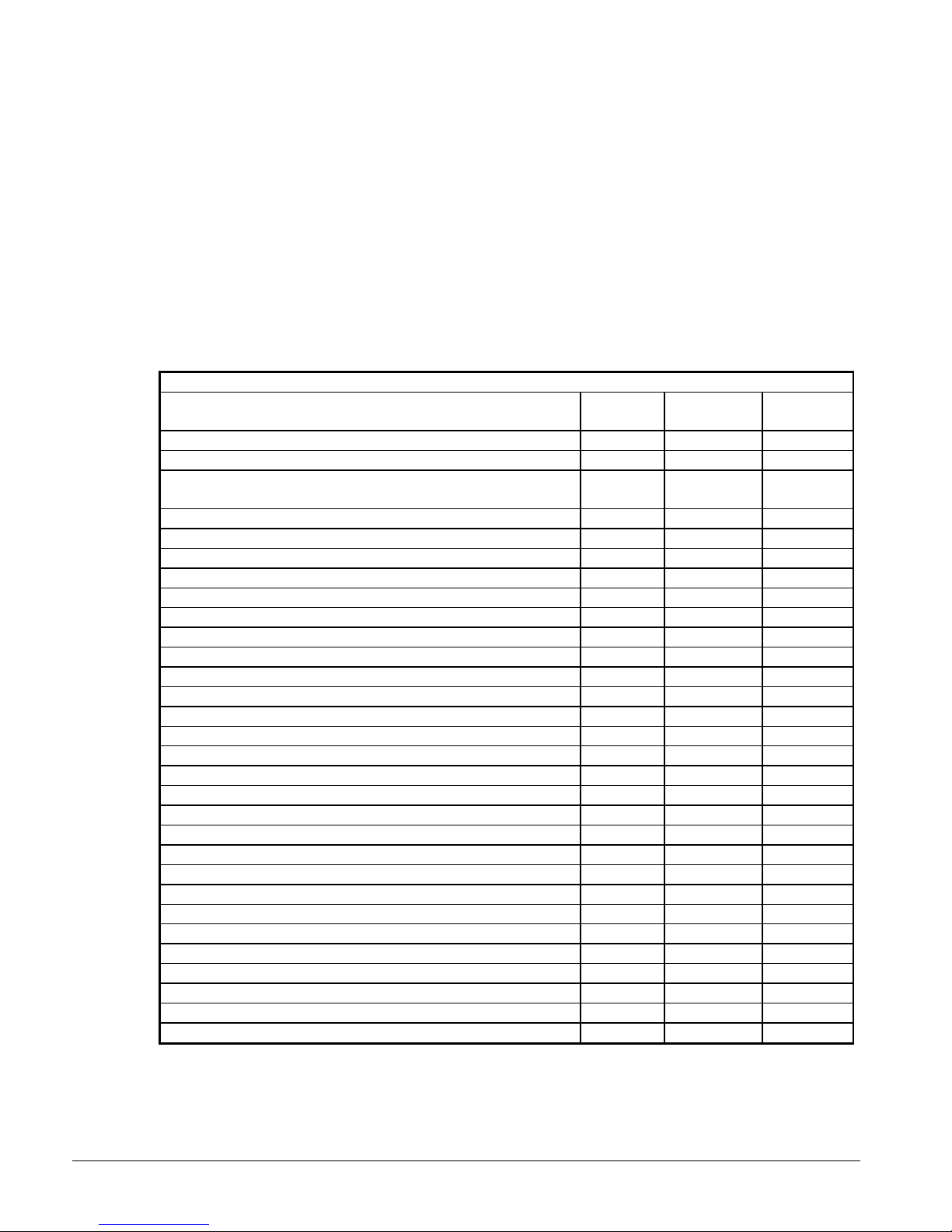
Do not use the sight glass on the EXV body for refrigerant charging. Its purpose is to view
Visually inspect unit for loose or damaged components and
the position of the valve.
Lead-Lag
A feature on all McQuay AGS air-cooled chillers is a system for alternating the sequence in
which the compressors start to balance the number of starts and run hours. Lead-Lag of the
refrigerant circuits is accomplished automatically through the MicroTech II controller.
When in the auto mode, the circuit with the fewest number of starts will be started first. If
all circuits are operating and a stage down in the number of operating compressors is
required, the circuit with the most operating hours will cycle off first. The operator can
override the MicroTech II controller, and manually select the lead circuit as circuit #1 or #2.
Preventative Maintenance Schedule
PREVENTATIVE MAINTENANCE SCHEDULE
OPERATION WEEKLY
General
Complete unit log and review (Note 3) X
MONTHLY
(Note 1)
ANNUAL
(Note 2)
visible leaks
Inspect thermal insulation for integrity X
Clean and paint as required X
Electrical
Sequence test controls X
Check contactors for pitting, replace as required X
Check terminals for tightness, tighten as necessary X
Clean control panel interior X
Clean control box fan filter (Note 7) X
Visually inspect components for signs of overheating X
Verify compressor and oil heater operation X
Megger compressor motor X
Refrigeration/Oil
Leak test X
Check liquid line sight glasses for clear flow X
Check compressor oil sight glass for correct level (oil charge) X
Check filter-drier pressure drop (see manual for spec) X
Check oil filter pressure drop (Note 6) X
Perform compressor vibration test X
Perform oil analysis test on compressor oil X
Condenser (air-cooled)
Clean condenser coils (Note 4) X
Check fan blades for tightness on shaft (Note 5) X
Check fans for loose rivets and cracks, check motor brackets X
Check coil fins for damage and straighten as necessary X
X
Notes:
1. Monthly operations include all weekly operations.
2. Annual (or spring start-up) operations include all weekly and monthly operations.
3. Log readings can be taken daily for a higher level of unit observation.
76
IMM AGS-2
Page 77

4. Coil cleaning can be required more frequently in areas with a high level of airborne particles.
5. Be sure fan motors are electrically locked out.
6. Replace the filter if pressure drop exceeds 20 psi.
7. The weekly fan filter cleaning schedule can be modified to meet job conditions. It is important
that the filter allows full air flow.
Warranty Statement
Limited Warranty
McQuay’s written Limited Product Warranty, along with any extended warranty expressly purchased is
the only warranty. Consult your local McQuay Representative for warranty details. Refer to Form
430285Y. To find your local McQuay Representative, go to www.mcquay.com.
Service
CAUTION
1. Service on this equipment must be performed by trained, experienced
refrigeration personnel familiar with equipment operation, maintenance, correct
servicing procedures, and the safety hazards inherent in this work. Causes for
repeated tripping of equipment protection controls must be investigated and
corrected.
2. Anyone servicing this equipment must comply with EPA requirements regarding
refrigerant reclamation and venting.
DANGER
Disconnect all power before doing any service inside the unit to avoid bodily injury or
death. MULTIPLE POWER SOURCES CAN FEED THE UNIT.
Liquid Line Filter-Driers
Replace the filter-drier cores any time excessive pressure drop is read across the filter-drier
and/or when bubbles occur in the sight glass with normal subcooling. There is one, twocore drier in each circuit. Models AGS 180 to 210 have economizers that incorporate an
additional filter-drier that should also be checked. The maximum recommended pressure
drop across the filter-drier is 7 psi at full load.
The filter-driers should also be changed if the moisture indicating liquid line sight glass
indicates excess moisture in the system, or an oil test indicates the presence of acid.
High acid cores may be used temporarily, but replaced after two day use.
IMM AGS-2
77
Page 78

The following is the procedure for changing the filter-drier core:
The standard unit pumpdown is set to stop pumpdown when 20 psig (138 kPa) suction
pressure is reached. To fully pump down a circuit beyond 20 psig (138 kPa) for service
purposes, a "Full Pumpdown" service mode can be activated using the keypad.
With Full Pumpdown = Yes, then the next time the circuit is pumped down, the pumpdown
will continue until the evaporator pressure reaches 15 psig (103 kPa) or 120 seconds have
elapsed, whichever occurs first. Upon completing the pumpdown, the "FullPumpDwn"
setpoint is automatically changed back to "No".
The procedure to perform a full service pumpdown for changing the filter-drier core is as
follows:
1. Under the "Alarm Spts", change the "FullPumpDwn" setpoint from "No" to "Yes".
2. Move the circuit switch to the OFF position. The compressor will unload to minimum
slide position and the unit will pump down.
3. Upon completing the full pumpdown per step 3, the "FullPumpDwn" setpoint is
automatically changed back to "No" which reverts back to standard 20 psig (138 kPa)
pumpdown stop pressure.
4. If the pumpdown does not go to 15 psig (103 kPa) on the first attempt, one more
attempt can be made by repeating the above steps. Do not repeat "FullPumpDwn" more
than once to avoid excessive screw temperature rise under this abnormal condition.
5. The circuit is now in the deepest pumpdown that can be achieved by the use of the
compressor. Close the two liquid line shutoff valves upstream of the filter-drier, on the
circuit to be serviced plus the optional suction shutoff valve. Manually open the EXV,
then remove the remaining refrigerant from the evaporator by the use of a refrigerant
recovery unit.
6. Loosen the cover bolts, remove the cap and replace the filters.
7. Evacuate and open valves.
Evacuate the lines through the liquid line manual shutoff valve(s) to remove
noncondensables that could have entered during filter replacement. Perform a leak check
before returning the unit to operation.
Compressor Slide Valves
The slide valves used for unloading the compressor are hydraulically actuated by pulses
from the load/unload solenoid as controlled by the circuit controller. See OM AGS for
details on the operation.
Electronic Expansion Valve (EXV)
The electronic expansion valve is located in each circuit’s liquid line entering the
evaporator.
The expansion valve meters the amount of refrigerant entering the evaporator to match the
cooling load. It does this by maintaining constant suction superheat. (Superheat is the
difference between the actual refrigerant temperature of the gas as it leaves the evaporator
and the saturation temperature corresponding to the evaporating pressure.) The EXV logic
controls the superheat between 4°F at 0% slide position and 8°F at 100% slide position.
The position of the valve can be viewed at any time by using the MicroTech II controller
keypad through the View Refrigerant menus. There are 6386 steps between closed and full
open. There is also a sight glass on the EXV to observe valve movement and to check if it
is open or closed visually.
78
IMM AGS-2
Page 79

Evaporator
The evaporator is a two-circuit, direct expansion, shell-and-tube type with water flowing
through the shell and refrigerant flowing in one pass through the tubes. The tubes are
internally enhanced to provide extended heat transfer surface. Normally, no service work is
required on the evaporator other than cleaning the water side in the event of improper water
treatment or contamination.
Charging Refrigerant
Note:
It is a good idea to record the normal values of refrigerant pressures, subcooling, superheat,
and evaporator and condenser approach temperatures during startup by the McQuay service
technician. This makes it easier to spot errant unit behavior.
Indications of a low refrigerant R-134a charge:
• Condenser subcoolong approaching 0 degrees F.
• Suction superheat higher than 10 to 12 degrees F.
• Bubbles in the sight glass.
Indications of a high refrigerant R-134a charge:
• Condenser pressure is abnormally high.
• Subcooling is abnormally high. Take note of the subcooling on the unit at startup and
use this value as a benchmark.
• EXV is at minimum position and discharge superheat is low (below 22 degrees F). The
circuit controller View Refrigerant Screen #7 displays the valve position and the valve
range. The minimum position occurs when the valve position value remains at the
lower limit of the range displayed.
AGS air-cooled screw compressor chillers are shipped factory-charged with a full operating
charge of refrigerant; but there can be times when a unit must be recharged at the job site.
Follow these recommendations when field charging. Refer to the unit operating charge
found in the Physical Data Tables beginning on page 26 for packaged units and page 60 for
remote evaporator units. An initial charge of 80% to 90% of the nameplate is assumed.
Unit charge adjustment should be done at 100% load, at normal cooling outdoor
temperature (preferably higher than 75°F (24°C), and with all fans on. Unit must be
allowed to run 15 minutes or longer so that the condenser fan staging and load is stabilized
at normal operating discharge pressure. For best results, charge with condenser pressure at
design conditions.
Each circuit of the evaporator has a sight glass located in the liquid line. If the unit can be
run at close to ARI conditions (95°F ambient temperature and 44°F chilled water), there
should be no bubbles in the sight glass, but this does not necessarily mean that the unit is
correctly charged. Charge until the superheat and subcooling temperatures are within
range. The discharge superheat should be above 22 degrees F.
Procedure to charge an undercharged AGS unit:
1. If a unit is low on refrigerant, first determine the cause before attempting to recharge
the unit. Locate and repair any refrigerant leak. Evidence of oil is a good indicator of
leakage. However, oil may not be visible at all leaks. Liquid leak detector fluids work
well to show bubbles at medium size leaks, but electronic leak detectors can be needed
to locate small leaks. Do not use oil/refrigerant detection additives.
2. Add the charge to the system only through the evaporator charging valve.
3. The charge must be added at the 100% slide valve position and above conditions.
IMM AGS-2
79
Page 80

4. Add sufficient charge to clear the conditions listed above under “Indications of a low
refrigerant R-134a charge”.
5. Overcharging of refrigerant will raise the condenser pressure and increase the
condenser subcooling.
Standard Controls
NOTE: A complete explanation of the MicroTech II controller and unit operation is contained
in the Operation Manual OM AGS.
Thermistor sensors
Evaporator leaving water temperature - This sensor is located on the evaporator water
outlet connection and is used for capacity control of the chiller and low water temperature
freeze protection.
Evaporator entering water temperature - This sensor is located on the evaporator water
inlet connection and is used for monitoring purposes and return water temperature reset
control.
Evaporator pressure transducer circuit #1, 2 - This sensor is located on the suction side
of the compressor (evaporator outlet) and is used to determine saturated suction refrigerant
pressure and temperature. It also provides low pressure freeze protection.
Condenser pressure transducer circuit #1, 2 - the sensor is located in the discharge line
and is used to read discharge pressure and saturated refrigerant temperature (calculated).
The transducer will signal the controller to hold load or unload the compressor if a rise in
head pressure occurs which is outside the MicroTech II controller setpoint limits. The
signal is also used in the calculation of discharge superheat.
Liquid pressure transducer #1, 2 – located on the liquid line ahead of the EXV. It is used
to determine liquid pressure and subcooling and is used to control the EXV.
Outside air - This sensor is located on the back of the control box. It measures the outside
air temperature, is used to determine if low ambient start logic is necessary, and can be the
reference for low ambient temperature lockout.
Suction temperature circuit #1, 2 - The sensor is located in a well on the suction line.
The purpose of the sensor is to measure refrigerant temperature and superheat.
Discharge line temperature circuit #1, 2 - The sensor is located in a well on the discharge
line. It measures the refrigerant temperature and is used to calculate discharge superheat.
Demand limit - This requires a field connection of a 4-20 milliamp DC signal from an
external source such as a building automation system. It will determine the maximum
number of cooling stages that can be energized.
Evaporator water temperature reset - This requires a 4-20 milliamp DC signal from a
building automation system or temperature transmitter to reset the leaving chilled water
setpoint.
High condenser pressure control
MicroTech II control is equipped with high pressure transducers on each refrigerant circuit.
The main purpose of the high pressure transducer is to maintain proper head pressure
control. It also sends a signal to the MicroTech II control to unload the compressor in the
event of an excessive rise in discharge pressure to 275 psig (1896 kPa). Also, MicroTech II
control will inhibit additional circuit loading at 267 psig (1841 kPa). The high pressure
switch trip setting is 282 psig (1944 kPa). The high pressure alarm is in response to the
signal sent by the pressure transducer.
80
IMM AGS-2
Page 81

Mechanical high pressure equipment protection control
The high pressure equipment protection control is a single pole, pressure-activated switch
that opens on a pressure rise. When the switch opens, the control circuit is de-energized,
dropping power to the compressor and fan motor contactors. The switch is factory set (nonadjustable) to open at 310 psig (2137 kPa) ±7 psig and reclose at 200 psig (1379 kPa) ±7
psig. Although the high pressure switch will close again at 200 psig (1379 kPa), the control
circuit will remain locked out and it must be reset through the MicroTech II control.
The control is mounted on the rear of the compressor. See page 71.
Compressor motor protection
The compressors are supplied with two types of motor protection. Solid state electronic
overloads mounted in the control box sense motor current to within 2% of the operating
amps. The MUST TRIP amps are equal to 140% of unit nameplate compressor RLA. The
MUST HOLD amps are equal to 125% of unit nameplate RLA. A trip of these overloads
can result from the unit operating outside of normal conditions. Repeat overload trips
under normal operation can indicate wiring or compressor motor problems. The overloads
are manual reset and must be reset at the overload, as well as through the MicroTech II
controller.
The compressors also have a solid state Guardister circuit that provides motor over
temperature protection. The Guardister circuit has automatic reset and gives a Starter Fault
(F75) that is cleared through the starter display and must also be reset through the
MicroTech II control.
Head pressure control (standard)
The MicroTech II controller automatically cycles the condenser fans in response to
condenser pressure. Each fan in a circuit is cycled independently for 4, 5 or 6 steps per
circuit, depending on the unit size. This maintains head pressure and allows the unit to run
at ambient air temperatures down to 35°F (1.7°C). The settings are adjustable through the
controller.
Each fan added has a decreasing percentage effect, so the control pressure band is smaller
when more fans are on and largest with only one or two fans on.
Unit operation with the standard control is satisfactory down to outdoor temperatures of
35°F (-1.7°C). Below this temperature, the VFD option is required to regulate the speed of
the first fan on the circuit to adequately control the discharge pressure. The VFD option
allows unit operation to 0°F (-17.8°C) outdoor temperature, assuming no greater than 5mph wind.
Head pressure control (optional low ambient)
The optional low ambient control includes a variable frequency drive (VFD) on the first fan
on each circuit. The remaining fans cycle based on discharge pressure. This control must
be used for operation in ambient temperatures below 35°F (1.7°C) down to 0°F (-17.8°C).
NOTE
: VFD and standard fan cycling will provide proper operating refrigerant discharge
pressures at the ambient temperatures listed for them, provided the coil is not affected by
the existence of wind. Louvers must be utilized for low ambient operation if the unit is
subjected to winds greater than 5 mph.
Compressor short cycling protection
The MicroTech II controller contains logic to prevent rapid compressor restarting.
Excessive compressor starts can be hard on starting components and create excessive motor
winding temperatures. The anti-cycle timers are set for a five-minute stop-to-start cycle and
a 20-minute start-to-start cycle. Both are adjustable through the MicroTech II control.
IMM AGS-2
81
Page 82

Controls, Settings and Functions
Table 44, Controls
DESCRIPTION FUNCTION SYMBOL SETTING RESET LOCATION
Compressor
Heaters
Compressor
Solenoid - Load
Compressor
Solenoid - Unload
Evaporator Heaters Help prevent evaporator freeze-up HTR-EVAP 38oF (3.3oC) N/A Evap. Barrel
Electronic
Expansion
Valve Board
Electronic
Expansion
Valve
Solid State Starter
Thermistor Card
Mechanical High
High Pressure
Switch
MicroTech II Unit
Controller
MicroTech II Circuit
Controllers
Oil Level Sensor Senses oil level in compressor OLS
Fan VFD (Optional) Controls discharge pressure FAN VFD In controller code N/A Power Panel
Control Panel
Heater
Lightning Arrestor
High Oil Delta-P
Switch
To provide heat to drive off liquid
refrigerant when compressor is off.
Loads compressor LOAD N/A N/A
Unloads the compressor UNLOAD N/A N/A
To provide power and step control to the
EXV stepper motors commanded by the
MT II.
To provide efficient unit refrigerant flow
and control subcooling.
To provide motor temperature protection
at about 220oF (104oC).
For UL, ETL, etc., safety code to prevent
high pressure above the relief valve.
To control unit functions. Refer to OM
AGS.
To control individual circuit functions.
One per circuit. Refer to OM AGS.
Maintain controller operation
To protect from high voltage spikes and
surges.
Protects compressor from running with
insufficient oil pressure
HTR1-COMPR
EXV-DRIVER N/A N/A Control Panel
EXV
K2 Fault
MHPR
UNIT
CONTROLLER
CIRCUIT
CONTROLLER
HTR-
CONTROL BOX
LA N/A N/A Power Panel
LPS Refer to OM AGS Auto
On, when
compressor is off.
In Controller
Code
None,
Inherent in design
Refer to
OM AGS
N/A
N/A
NC with oil
present
On at 40°F N/A Control Panel
N/A
N/A
Auto Power Panel
Auto Control Panel
Refer to
OM AGS
Refer to
OM AGS
N/A
On the
Compressor
On the
Compressor
On the
Compressor
In Main Liquid
Line
Control Panel
Control Panel
On
compressor
82
IMM AGS-2
Page 83

Troubleshooting Chart
Table 45, Troubleshooting
PROBLEM POSSIBLE CAUSES POSSIBLE CORRECTIVE STEPS
Compressor will not
run.
Compressor Noisy
or Vibrating
Compressor
Overload K2
Tripped or Circuit
Breaker Trip or
Fuses Blown
Compressor Will
Not Load or Unload
High Discharge
Pressure
Low Discharge
Pressure
Low Suction
Pressure
Low Oil Level Trip
High Suction
Pressure
1. Main power switch open.
2. Unit S1 system switch open.
3. Circuit switch, CS in pumpdown position.
4. Chilled water flow switch not closed.
5. Circuit breakers open.
6. Fuse blown or circuit breakers tripped.
7. Compressor overload tripped.
8. Defective compressor contactor or contactor coil.
9. System shut down by protection devices.
10. No cooling required.
11. Motor electrical trouble.
12. Loose wiring.
1. Compressor Internal problem.
2. Oil injection not adequate.
1. Low voltage during high load condition.
2. Loose power wiring.
3. Power line fault causing unbalanced voltage.
4. Defective or grounded wiring in the motor.
5. High discharge pressure.
1. Defective capacity control solenoids.
2. Unloader mechanism defective.
1. Noncondensables in the system.
2. Fans not running.
3. Fan control out of adjustment.
4. System overcharged with refrigerant.
5. Dirty condenser coil.
6. Air recirculation from fan outlet into unit coils.
7. Air restriction into unit.
1. W ind effect or a low ambient temperature.
2. Condenser fan control not correct.
3. Low suction pressure.
4. Compressor operating unloaded.
1. Inadequate refrigerant charge quantity.
2. Clogged liquid line filter-drier.
3. Expansion valve malfunctioning.
4. Insufficient water flow to evaporator.
5. W ater temperature leaving evaporator is too low.
6. Evaporator tubes fouled.
7. Suction valve (partially) closed.
8. Glycol in chilled water system
1. Insufficient oil.
2. Low discharge pressure.
1. Excessive load - high water temperature.
2. Compressor unloaders not loading compressor.
3. Superheat is too low.
4. System overcharged
1. Close switch.
2. Check unit status on MicroTech II display. Close switch.
3. Check circuit status on MicroTech II display. Close switch. Check
pump operation for flow.
4. Check unit status on MicroTech display. Close switch.
5. Close circuit breakers.
6. Check electrical circuits and motor windings for shorts or grounds.
Investigate for possible overloading. Check for loose or corroded
connections. Reset breakers or replace fuses after fault is corrected.
7. Overloads are manual reset. Reset overload at button on overload.
Clear alarm on MicroTech II display.
8. Check wiring. Repair or replace contactor.
9. Determine type and cause of shutdown and correct problem before
attempting to restart.
10. Check control settings. Wait until unit calls for cooling.
11. See 6,7,8 above.
12. Check circuits for voltage at required points. Tighten all power wiring
terminals.
1. Contact McQuayService.
2. Check that oil sight glass has oil visible during steady operation
Check pressure drop across oil filter and oil separator sight glasses
1. Check supply voltage for excessive voltage drop.
2. Check and tighten all connections.
3. Check supply voltage.
4. Check motor and replace if defective.
5. See corrective steps for high discharge pressure.
1. Check solenoids for proper operation. See capacity control section.
2. Contact McQuayService .
1. Remove noncondensables from the condenser coil after shutdown per
EPA regulations.
2. Check fan fuses and electrical circuits.
3. Check that fan setup in the controller matches unit fan number. Check
MicroTech II condenser pressure sensor for proper operation.
4. Check discharge superheat and condenser subcooling. Remove the
excess charge.
5. Clean the condenser coil.
6. Remove the cause of recirculation.
7. Remove obstructions near unit.
1. Protect unit against excessive wind into vertical coils.
2. Check that fan setup in the MicroTech II controller matches unit fan
number. Check VFD fan on units with VFD option.
3. See corrective steps for low suction pressure.
4. See corrective steps for failure to load.
1. Check liquid line sight glass. Check unit for leaks. Repair and
recharge to clear sight glass at full load, all fans on, 75°F min OAT..
2. Check pressure drop across the filter-drier. Replace filter-driers.
3. Check expansion valve superheat and valve opening position.
Replace valve only if certain valve is not working.
4. Check water pressure drop across the evaporator and adjust gpm.
5. Adjust water temperature to higher value.
6. Inspect by removing water piping. Clean chemically.
7. Open valve.
8. Check glycol concentration
1. Check oil line and separator sight glasses.
2. Faulty EXV.
1. Reduce load or add additional equipment.
2. See corrective steps below for failure of compressor to load.
3. Check superheat on MicroTech II display. Check suction line sensor
installation and sensor.
4. Check charge, an overcharge raises suction pressure
IMM AGS-2
83
Page 84

Periodic Maintenance Log
Date of inspection: Address:
Facility/job name: City/State:
Unit model number: Physical location of unit:
Unit serial number: Service technical (name):
Software identification:
Operating hours: Compressor #1 Compressor #2
Number of starts Compressor #1 Compressor #2
Follow up service required: Yes No
General Actions to be Taken
Upper part of report completed: Yes No Fill in above
Compressor operation: Yes No Explain all “No” checks
1. Mechanical operation acceptable (noise, vibration, etc.)?
2. Look at cycling and cooling, is unit controlling at set points?
3. No refrigerant leaks (full liquid sight glass)?
4. Liquid line moisture indicator shows dry system?
5. Proper condensing fan operation?
6. Condenser coil clean?
7. No corrosion or paint problems?
Compressor electrical operation:
8. Satisfactory electrical operation?
9. MicroTech II hardware operation satisfactory?
10.
MicroTech II software operation satisfactory?
11. Unit status %
Data from MicroTech II Controller:
12. Circuit status 1 % Capacity Circuit status 2 % Capacity
13. Water temperature – Evaporator: Entering/Leaving /
Circuit #1 Circuit #2
14. No. of fan states active:
15. Evaporator pressure:
16. Condenser pressure:
17. EXV position – Steps open or percent open:
18. Superheat:
19. Subcooling:
20. Liquid line temperature:
21. Outside air temperature:
22. Leaving evaporator setpoint temperature:
23. Reset option programmed? Yes No Ice storage unit? Yes No
24. Is VFD included? Yes No VFD operation OK? Yes No
25. Current alarm: ___ ___ ___ Circuit #1 ______ Circuit #2 ______
26. Previous alarm – Show all: Alarm Type Date
Circuit #1
Circuit #2
27. Compressor starts See note 1 Circuit #1 _________________
Circuit #2 _________________
28. Compressor run hours Circuit #1 _________________
Circuit #2 _________________
Data at Job Site:
29. Volts: L1_____ L2_____ L3_____
30. Amps: Comp #1 Ph 1____ PH 2____ PH 3____
31. Amps: Comp #2 PH 1____ PH 2____ PH 3____
32. Vibration – Read every six months using IRD (or equal) unfiltered at flat on top of motor end: ______ In/Sec Comp #1
______ In/Sec Comp #2
NOTE 1: If the number of starts exceeds the number of run hours, the unit is short cycling. This must be corrected as it can reduce compressor life.
84
IMM AGS-2
Page 85

IMM AGS-2
85
Page 86

86
IMM AGS-2
Page 87

Page 88

This document contains the most current product information as of this printing. For the most up-todate product information, please go to www.mcquay.com
(800) 432-1342 • www.mcquay.com IMM AGS-2 (07/08)
 Loading...