

Page 1
Operation Manual
OM AGSC-11
Air-Cooled Screw Compressor Chiller
AGS 120C through AGS 210C
Software Version AGSD30101G/H
60 Hertz, R-134a
Group: Chiller
Part Number: 331373501
Date: May 2008
Supersedes: OM AGSC-10
Page 2
Table of Contents
©2007 McQuay International
ISO Certified facility
CONTROLLER FEATURES......................... 4
GENERAL DESCRIPTION........................... 5
Power Panel Layout...................................... 6
Control Panel Layout.................................... 7
COMPONENT DESCRIPTION .................... 8
Definitions .................................................... 8
Unit and Circuit Controller Description ..... 11
SEQUENCE OF OPERATION.................... 12
CONTROL OPERATION ............................17
UNIT CONTROLLER ..................................17
Inputs/Outputs ............................................17
Setpoints .....................................................18
UNIT CONTROLLER FUNCTIONS..........20
Parameter Definitions .................................20
Unit Enable ................................................. 20
Unit Mode Selection................................... 21
Unit States................................................... 23
Ice Mode Start Delay.................................. 24
Evaporator Pump Control........................... 24
Leaving Water Temperature (LWT) Reset.. 25
Unit Capacity Overrides .............................27
Building Automation System Interface.......28
Quiet Night Operation ................................ 28
CIRCUIT CONTROLLER........................... 29
Inputs/Outputs ............................................29
Setpoints .....................................................30
CIRCUIT CONTROLLER FUNCTIONS ..32
Refrigerant Calculations .............................32
Circuit Operating Mode.............................. 33
Compressor Control.................................... 33
Pumpdown .................................................. 37
Slide Positioning......................................... 37
Unit controllers are LONM
ARK
certified with an optional LONW
ORKS
communications module
Expansion Valve (EXV) Control.................39
Oil Heater Control.......................................41
Economizer Control....................................42
Starter Communications..............................43
Condenser Fan Control ...............................45
ALARMS AND EVENTS..............................48
Unit Stop Alarms.........................................48
Unit Events..................................................49
Circuit Stop Alarms.....................................49
Circuit Events..............................................53
Alarm Logging............................................54
Event Logging.............................................55
USING THE CONTROLLER ......................56
Security .......................................................58
Entering Passwords.....................................58
Editing Setpoints.........................................58
Clearing Alarms ..........................................59
Unit Controller Menus ................................59
Circuit Controller Menus ............................68
SEE "ALARMS AND EVENTS ...................69
Unit Stop Alarms.........................................69
Unit Events..................................................70
Circuit Stop Alarms.....................................70
Circuit Events..............................................74
Alarm Logging............................................75
Event Logging.............................................76
Editing Review............................................82
START-UP AND SHUTDOWN ...................84
Temporary Shutdown..................................84
Extended (Seasonal) Shutdown ..................85
BAS INTERFACE .........................................87
FIELD WIRING DIAGRAM........................91
reserve the right to make changes in design and construction at anytime without notice. ™® The following are trademarks or
registered trademarks of their respective companies: BACnet from ASHRAE; LONM
logo are managed, granted and used by LONM
from Copeland Corporation; ElectroFin from AST ElectroFin Inc.; Modbus from Schneider Electric; FanTrol, MicroTech II, Open
Choices, and SpeedTrol from McQuay International.
2 OM AGSC-11
. Illustrations and data cover the McQuay International product at the time of publication and we
ARK
ARK
International under a license granted by Echelon Corporation; Compliant Scroll
, LonTalk, LONW
ORKS
, and the LONM
ARK
Page 3
This manual provides setup, operating, and troubleshooting information for the McQuay
MicroTech ΙΙ controller for Model AGS-C vintage, air-cooled, rotary screw compressor
chillers. Please refer to the current version of the installation and maintenance manual IMM
AGSC (available on www.mcquay.com) for information relating to the unit itself.
Among other revisions and upgrades, this software version modifies EXV valve and
economizer operation, modifies start logic and some alarms and events, changes some set
points, and adds to the BAS interface logic.
Software Version: This manual covers units with Software Version AGSD30101G and H.
Version G contains the above changes and Version H only corrects an EXV bug and does
not change this manual. The unit’s software version number can be viewed by pressing the
MENU and ENTER keys (the two right keys) simultaneously. Then, pressing the MENU
key will return to the Menu screen.
BOOT Version: 3.0F
BIOS Version: 3.62
!
DANGER
Electric shock hazard. Can cause personal injury or equipment damage. This equipment
must be properly grounded. Connections to, and service of, the MicroTech II control panel
must be performed only by personnel who are knowledgeable in the operation of the
equipment being controlled.
!
WARNING
Static sensitive components. A static discharge while handling electronic circuit boards can
cause damage to the components. Discharge any static electrical charge by touching the
bare metal inside the control panel before performing any service work. Never unplug any
cables, circuit board terminal blocks, or power plugs while power is applied to the panel.
NOTICE
This equipment generates, uses and can radiate radio frequency energy and, if not installed and used
in accordance with this instruction manual, can cause interference to radio communications. Operation
of this equipment in a residential area can cause harmful interference, in which case the user will be
required to correct the interference at the user’s own expense.
McQuay International Corporation disclaims any liability resulting from any interference or for the
correction thereof.
Temperature and Humidity Limitations
The MicroTech ΙΙ controller is designed to operate within an ambient temperature range of
-20°F to +149°F (-29°C to +65.1°C) with a maximum relative humidity of 95% (noncondensing).
Language
This version of the software is set up for English language and inch-pounds units of measure
only.
OM AGSC-11 3
Page 4

Controller Features
• Readout of the following temperature and pressure readings:
• Entering and leaving chilled water temperature
• Saturated evaporator refrigerant temperature and pressure
• Saturated condenser temperature and pressure
• Outside air temperature
• Suction line, liquid line, and discharge line temperatures − calculated superheat for
discharge and suction lines
• Automatic control of primary and standby chilled water pumps. The control will start one
of the pumps (based on lowest run-hours) when the unit is enabled to run (not necessarily
running on a call for cooling) and when the water temperature reaches a point of freeze
possibility.
• Three levels of security protection against unauthorized changing of setpoints and other
control parameters.
• Warning and fault diagnostics to inform operators of warning and fault conditions in plain
language. All events and alarms are time- and date-stamped for identification of when the
fault condition occurred. In addition, the operating conditions that existed just prior to an
alarm shutdown can be recalled to aid in isolating the cause of the problem.
• Twenty-five previous alarms and related operating conditions are available.
• Remote input signals for chilled water reset, demand limiting, and unit enable.
• Test mode allows the service technician to manually control the controllers’ outputs and
can be useful for system checkout.
• Building Automation System (BAS) communication capability via LONW
Modbus, or BACnet open standard protocols for all BAS manufacturers-simplified
with McQuay’s Open Choices feature.
• Service Test mode for troubleshooting controller hardware.
• Pressure transducers for direct reading of system pressures. Preemptive control of low
evaporator pressure conditions and high discharge temperature and pressure to take
corrective action prior to a fault trip.
• Distributed control-one unit controller and two independent circuit controllers improves
unit reliability.
• Quiet Night operation limits unit capacity and fan operation to reduce unit sound levels
during low-load, night-time operation.
ORKS
,
4 OM AGSC-11
Page 5
General Description
General Description
The AGS-C MicroTech ΙΙ distributed control system consists of multiple microprocessorbased controllers that provide monitoring and control functions required for the controlled,
efficient operation of the chiller. The system consists of the following components:
• Unit Controller, one per chiller − controls functions and settings that apply to the unit
and communicates with the other controllers. It is located in the control panel and is
labeled “UNIT CONTROL”.
• Circuit Controllers for each compressor/circuit that control compressor functions and
settings specific to the circuit. The controllers are also located in the control panel and
are labeled “CIRCUIT CONROL”.
In addition to providing all normal operating controls, the MicroTech II control system
monitors equipment protection devices on the unit and will take corrective action if the
chiller is operating outside of its normal design envelope. If an alarm condition develops,
the controller will shut down the compressor, or entire unit, and activate an alarm output.
Important operating conditions at the time an alarm condition occurs are retained in the
controller’s memory to aid in troubleshooting and fault analysis.
The system is protected by a password scheme that allows access only by authorized
personnel. The operator must enter the operator password into the controller's keypad before
any setpoints can be altered.
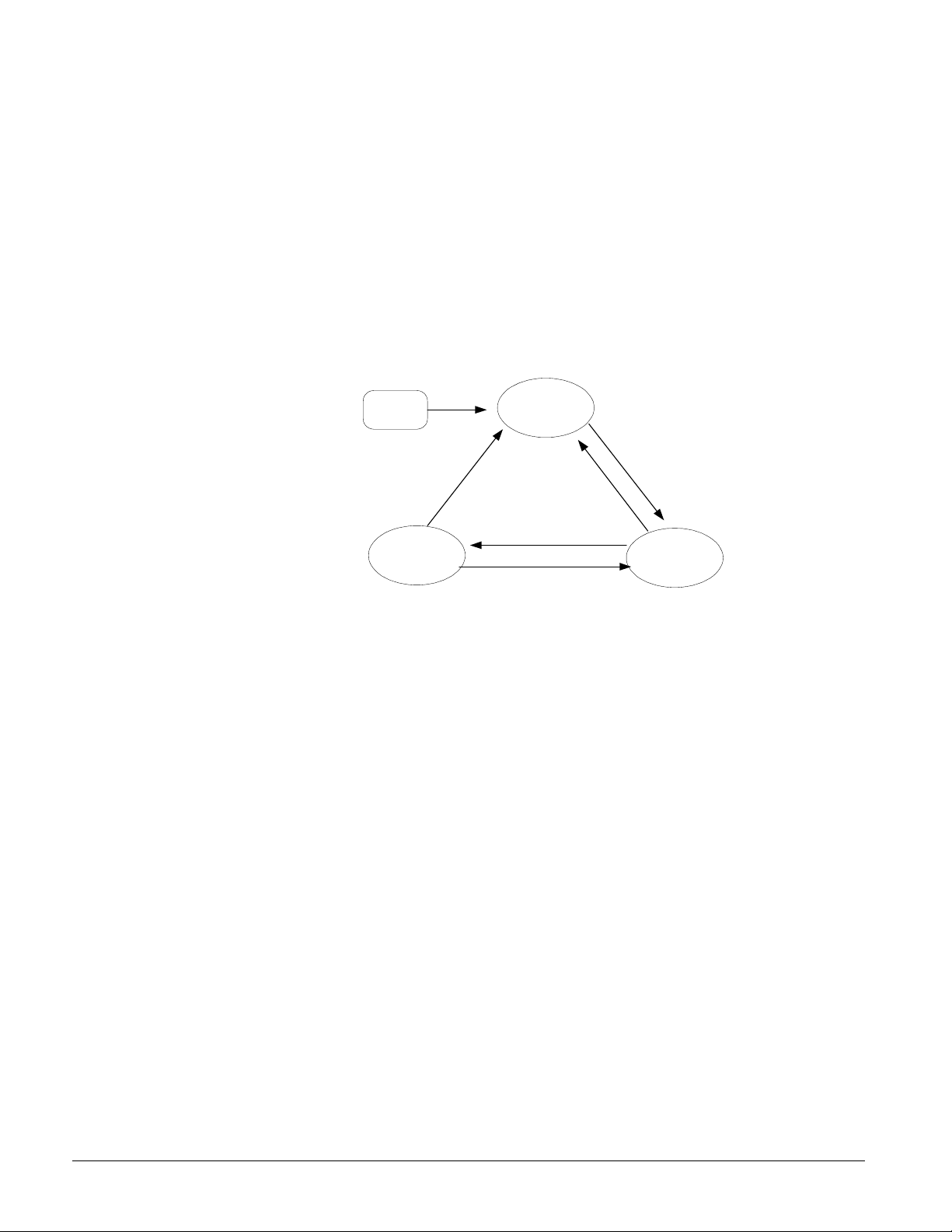
Control Architecture
Figure 1, Major Control Components
BAS Interface-
Modbus,
BACnet,
Lonworks
Chiller
RS485/
LON
Unit Controller
4x20 LCD
Solid
State
Starter
RS485 RS485
Circuit Controller
4x20 LCD
Solid
State
Starter
Circuit Controller
4x20 LCD
Carel pLAN
pLAN Addressing
The pLAN (proprietary local area network) addressing is based on a common scheme used
on all pLAN networked MicroTech II controllers. Only three addresses are needed, and are
designated as shown in the table below.
Controller Address
Dip Sw 1
Position
Unit 5 Up Down Up
Circuit 1 1 Up Down Down
Circuit 2 2 Down Up Down
The Dip switches are located on the upper front of the controller above the screen.
Dip Sw 2
Position
Dip Sw 3 Position
OM AGSC-11 5
Page 6
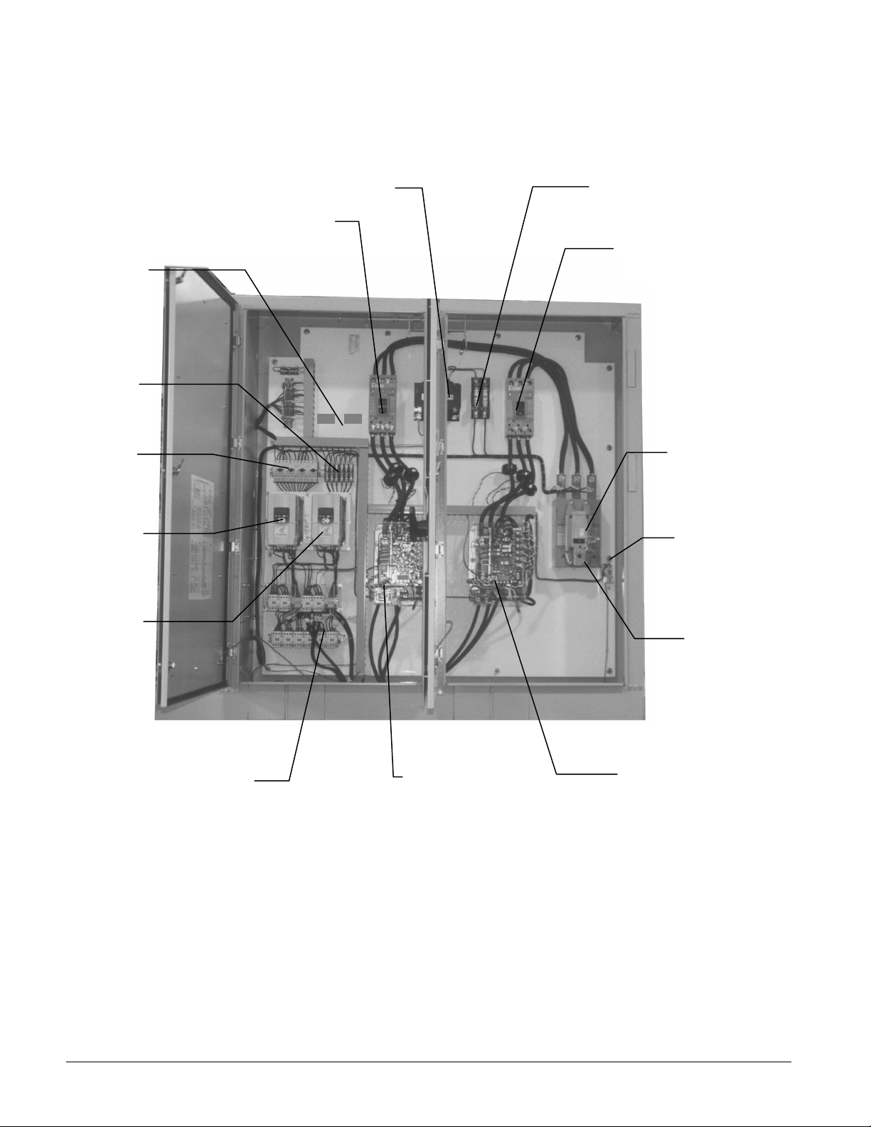
Power Panel Layout
Control Transformer
Fuses
Breakers
The power panel is located on the front of the unit, to the right of the control panel.
Figure 2, Power Panel Components (Single Point Power)
Line
Reactors
for
Optional
VFD
Fan
Circuit
Cir#2 Fan
VFD
(Optional)
Cir#2 Circuit Breaker,
Single Point Power
Primary Control Power
Fuses
Cir#1 Circuit Breaker,
Single Point Power
Unit Circuit
Breaker
(Optional)
Grounding
Lug
Cir#1 Fan
VFD
Fan Contactors
Cir#2 Starter
Incoming
Power
Connection
Cir#1 Starter
6 OM AGSC-11
Page 7
Control Panel Layout
The control panel is located on the front of the unit, to the left of the power panel.
Distributed control architecture enhances unit reliability. Each compressor circuit has its own
microprocessor controller so that if one circuit controller is inoperative, the other circuit controller
will still be able to run its compressor and circuit components.
Figure 3, Control Panel Components
T2 T13 T14 T15 T23 T24 T25
T2 24V Unit Controller Transformer
T13, T23 24V Circuit Controller Transformers
T14, T24 24V Compressor Load/Unload Trns.
T15, T25 24V EXV Driver Transformer
Transformers
Unit Controller
Cir#1 Controller
Cir#2 Controller
OM AGSC-11 7
Page 8

Component Description
Definitions
Active Setpoint
The active setpoint is the setting in effect at any given moment. This variation occurs on
setpoints that can be altered during normal operation. Resetting the chilled water leaving
temperature setpoint by one of several methods, such as return water temperature, is an
example.
Active Capacity Limit
The active setpoint is the setting in effect at any given moment. Any one of several external
inputs can limit a compressor’s capacity below its maximum value.
Condenser Saturated Temperature Target
The saturated condenser temperature target is calculated by first using the following
equation:
Sat condenser temp target raw = 0.833(evaporator sat temp) + 68.34
The “raw” value is the initial calculated value. This value is then limited to a range defined
by the Condenser Saturated Temperature Target minimum and maximum setpoints. These
setpoints simply cut off the value to a working range, and this range can be limited to a
single value if the two setpoints are set to the same value.
CPU Error
These are problems caused by a malfunction of the central processing unit.
Dead Band
The dead band is a range of values surrounding a setpoint such that a change in the variable
occurring within the dead band range causes no action from the controller. For example, if a
temperature setpoint is 44°F and it has a dead band of ± 2 degrees F, nothing will happen
until the measured temperature is less than 42°F or more than 46°F.
DIN
Digital input, usually followed by a number designating the number of the input.
Discharge Superheat
Discharge superheat shall be calculated for each circuit using the following equation:
Discharge Superheat = Discharge Temperature – Condenser Saturated Temperature
Error
In the context of this manual, “Error” is the difference between the actual value of a variable
and the target setting or setpoint.
Evaporator Approach
The evaporator approach is calculated for each circuit. The equation is as follows:
Evaporator Approach = LWT – Evaporator Saturated Temperature
Evap Recirc Timer
A timing function, with a 30-second default, that holds off any reading of chilled water for
the duration of the timing setting. This delay allows the chilled water sensors (especially
water temperatures) to take a more accurate reading of the chilled water system conditions.
8 OM AGSC-11
Page 9

EXV
Electronic expansion valve, used to control the flow of refrigerant to the evaporator,
controlled by the circuit microprocessor.
High Saturated Condenser – Hold Value
High Cond Hold Value = Max Saturated Condenser Value – 5°F
This function prevents the compressor from loading whenever the pressure approaches
within 5 degrees of the maximum discharge pressure. The purpose is to keep the compressor
online during periods of possibly temporary elevated pressures.
High Saturated Condenser – Unload Value
High Cond Unload Value = Max Saturated Condenser Value – 3°F
This function unloads the compressor whenever the pressure approaches within 3 degrees of
the maximum discharge pressure. The purpose is to keep the compressor online during
periods of possibly temporary elevated pressures.
High Superheat Error
The degrees of temperature difference between 40°F and the actual discharge temperature.
Light Load Stg Dn Point
The percent load point at which one of two operating compressors will shut off, transferring
the unit load to the remaining compressor.
Load Limit
An external signal from the keypad, the BAS or a 4-20 ma signal that limits the compressor
loading to a designated percent of full load. Frequently used to limit unit power input.
Load Balance
Load balance is a technique that equally distributes the total unit load among the running
compressors on a unit or group of units.
Low Ambient Lockout
Prevents the unit from operating (or starting) at ambient temperatures below the setpoint.
Lockout cancels when ambient temperature rises 5-degfrees above the setpoint
Low Pressure Hold Setpoint
The psi evaporator pressure setting at which the controller will not allow further compressor
loading.
Low/High Superheat Error
The difference between actual evaporator superheat and the superheat target.
LWT
Leaving water temperature. The “water” is any fluid used in the chiller circuit.
LWT Error
Error in the controller context is the difference between the value of a variable and the
setpoint. For example, if the LWT setpoint is 44°F and the actual temperature of the water at
a given moment is 46°F, the LWT error is +2 degrees.
LWT Slope
The LWT slope is an indication of the trend of the water temperature. It is calculated by
taking readings of the temperature every few seconds and subtracting them from the previous
value, over a rolling one minute interval.
ms
Milli-second
OM AGSC-11 9
Page 10

Maximum Saturated Condenser Temperature
The maximum saturated condenser temperature allowed is calculated based on the
compressor operational envelope.
OAT
Outside ambient air temperature
Offset
Offset is the difference between the actual value of a variable (such as temperature or
pressure) and the reading shown on the microprocessor as a result of the sensor signal. See
page 31.
pLAN
Peco Local Area Network is the proprietary name of the network connecting the control
elements.
Refrigerant Saturated Temperature
Refrigerant saturated temperature is calculated from the pressure sensor readings for each
circuit. The pressure is fitted to an R-134a temperature/pressure curve to determine the
saturated temperature.
Soft Load
Soft Loading is a configurable function used to ramp up the unit capacity over a given time
period, usually used to influence building electrical demand by gradually loading the unit.
SP
Setpoint
SSS
Solid state starter as used on McQuay screw compressors.
Suction Superheat
Suction superheat is calculated for each circuit using the following equation:
Suction Superheat = Suction Temperature – Evaporator Saturated Temperature
Stage Up/Down Accumulator
The accumulator can be thought of as a bank storing occurrences that indicate the need for
an additional fan.
Stageup/Stagedown Delta-T
Staging is the act of starting or stopping a compressor or fan when another is still operating.
Startup and Stop is the act of starting the first compressor or fan and stopping the last
compressor or fan. The Delta-T is the “dead band” on either side of the setpoint in which no
action is taken.
Stage Up Delay
The time delay from the start of the first compressor to the start of the second.
Startup Delta-T
Number of degrees above the LWT setpoint required to start the first compressor.
Stop Delta-T
Number of degrees below the LWT setpoint required for the last compressor to stop.
VDC
Volts, Direct current, sometimes noted as vdc.
VFD
Variable Frequency Drive, a device used to vary an electric motor’s speed.
10 OM AGSC-11
Page 11
Unit and Circuit Controller Description
ALARM
Hardware Structure
The controllers are fitted with a 16-bit microprocessor for running the control program.
There are controller terminals for connection to the controlled devices (for example: solenoid
valves, expansion valves, chilled water pumps). The program and settings are saved
permanently in FLASH memory, preventing data loss in the event of power failure without
requiring a back-up battery. The controllers also have optional remote communication
access capability for a BAS interface using standard protocols.
Each chiller has one unit controller and a circuit controller for each of two compressor
circuits. The controllers are connected and communicate via a pLAN (local area network).
The circuit controllers communicate with, and control the operation of, the compressor's
solid state starter and the circuit’s electronic expansion valve (EXV).
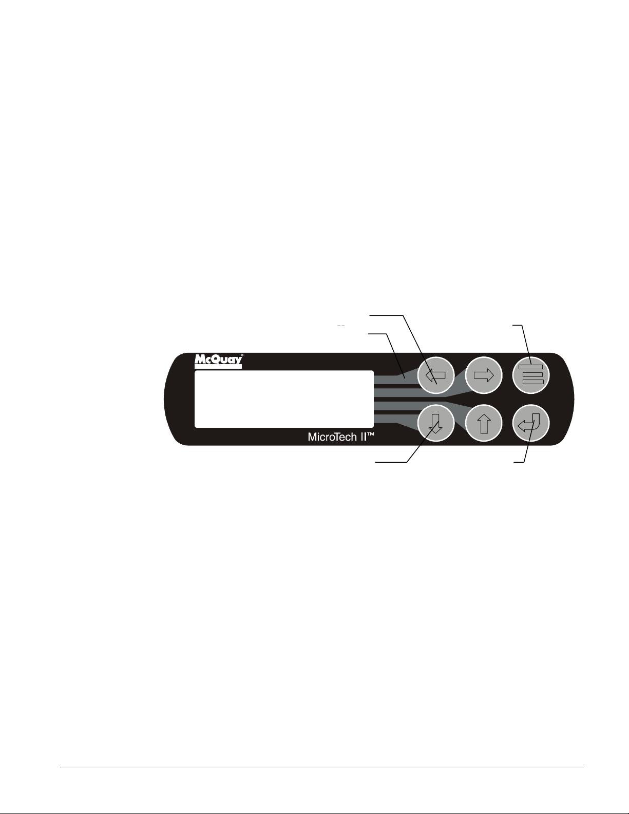
Keypad
A 4-line by 20-character liquid crystal display and 6-button keypad are mounted on the unit
and compressor controllers.
Figure 4, Keypad
Red Alarm Light Behind Arrow
MENU Key
Key-to-Screen Pathway
Air Conditioning
<
VIEW
<
<
SET
ARROW Keys (4)
ENTER Key
The four arrow keys (UP, DOWN, LEFT, RIGHT) have three modes of use.
1. Scroll between data screens in the direction indicated by the arrows (default mode).
2. Select a specific data screen in the menu matrix using dynamic labels on the right side of
the display such as ALARM, VIEW, etc. (pressing the MENU key enters this mode).
For ease of use, a visual pathway connects the appropriate button to its respective label
on the screen.
3. Change field values in setpoint programming mode as follows:
LEFT key = Default (D) RIGHT key = Cancel (C)
UP key = Increase (+) DOWN key = Decrease (-)
These four programming functions are indicated by a one-character abbreviation ( ) on the
right side of the display. This programming mode is entered by pressing the ENTER key.
OM AGSC-11 11
Page 12
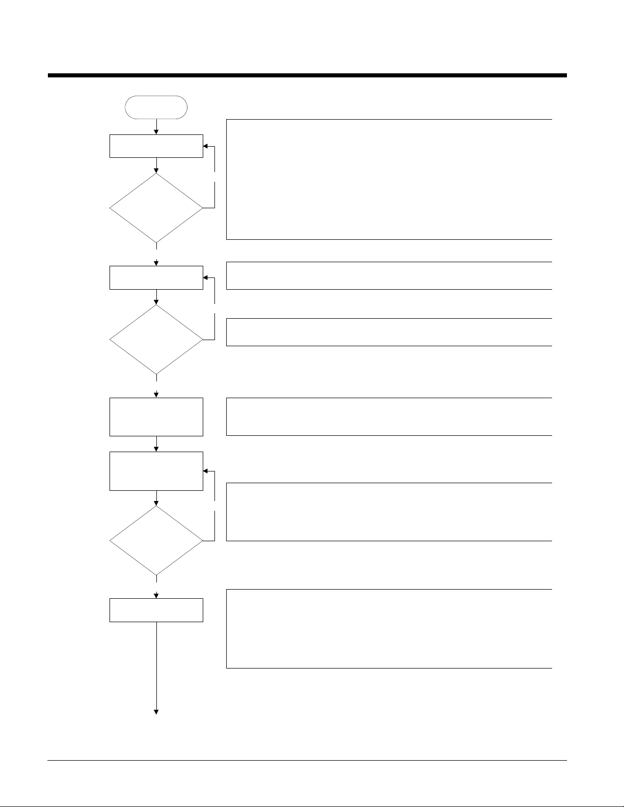
Sequence of Operation
Unit power up
The chiller may be disabled via the unit switch, the remote switch, the keypad
Unit in Off state
Is unit enabled?
Yes
Evaporator pump output on
Is flow present?
enable setting, or the BAS network. In addition, the chiller will be disabled if both
circuits are disabled, either because of an alarm or the circuit pumpdown switch on
each circuit, or if there is a unit alarm. If the chiller is disabled, the unit status
display will reflect this and also show why it is disabled.
No
If the unit switch is off, the unit status will be
disabled due to network command, the unit status will be
the remote switch is open, the unit status will be
alarm is active, the unit status will be
are enabled, the unit status will be
If the chiller is enabled, then the unit will be in the Auto state and the evaporator
water pump output will be activated.
No
The chiller will then wait for the flow switch to close, during which time the unit
status will be
Auto:Wait for flow
Off:Unit Switch
Off:Remote Switch
Off:Unit Alarm
Off:All Cir Disabled
.
. If the chiller is
Off:BAS Disable
. When
. When a unit
. In cases where no circuits
.
Yes
Wait for chilled water loop to
recirculate.
Keep pump output on while
unit is enabled.
Is there enough load to
start chiller?
Yes
Start first circuit.
After establishing flow, the chiller will wait some time to allow the chilled water loop
to recirculate for an accurate reading of the leaving water temperature. The unit
status during this time is
Auto:Evap Recirc
.
The chiller is now ready to start if enough load is present. If the LWT is not high
enough to start, the unit status will be
No
If the LWT is high enough to start, the unit status will be
Auto:Wait for load
.
Auto
. A compressor can
start at this time.
The first circuit to start is generally the one with the least number of starts, or circuit
one if there is a tie. This circuit will go through its start sequence at this point.
A number of fans may be started with the compressor based on the OAT. Fan
stages will be added/removed as needed to control condenser pressure. The EXV
will begin controlling at this point as well. The compressor cannot start loading until
it has at least 22o discharge superheat for more than 30 seconds.
12 OM AGSC-11
Page 13
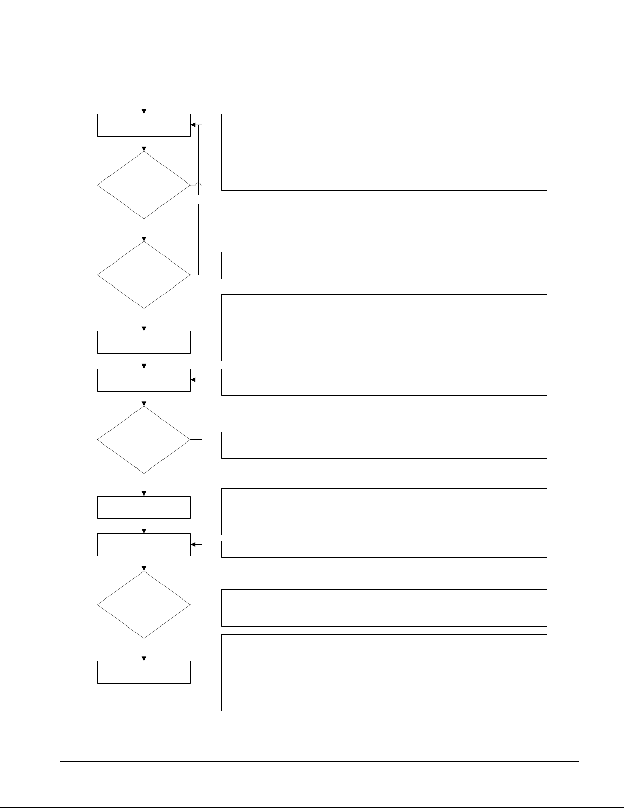
Load/unload as needed to
satisfy load.
Is more capacity
needed to satisfy load?
Yes
Has the stage up time
delay expired?
Yes
Start second circuit.
Load/unload as needed to
satisfy load.
No
The first circuit will load and unload as needed in an attempt to satisfy the load. It
will eventually get to a point where it is considered to be at full load. A circuit is at
full load when it reaches 75% slide target, it reaches the max slide target setting, or
it encounters a problem and is running in an inhibited state.
No
If a single circuit is not enough to satisfy the load, the second circuit will need to be
started.
A minimum time must pass between the start of the first circuit and the second
circuit.
The second circuit will go through its start sequence at this point.
A number of fans may be started with the compressor based on the OAT. Fan
stages will be added/removed as needed to control condenser pressure. The EXV
will begin controlling at this point as well. The compressor cannot start loading until
it has at least 22o discharge superheat for more than 30 seconds.
Both circuits will now load/unload as needed to satisfy the load. In addition, they will
load balance so that both circuits are providing nearly equal capacity.
No
Can one circuit handle
the load?
Yes
Shut down one circuit.
Load/unload as needed to
satisfy load.
Is load satisfied?
Yes
Shut down last circuit.
As the load drops off, the circuits will unload accordingly. If the LWT gets low
enough, or both circuits unload enough, one circuit can shut off.
The first circuit to shut off is generally the one with the most run hours. The circuit
will do a pumpdown by closing the EXV and continuing to run the compressor until it
reaches the pumpdown pressure or exceeds the pumpdown time limit. Then, the
compressor and all fans will be turned off.
The single running circuit will load/unload as needed to satisfy the load.
No
With one circuit running, the load may drop off to the point where even minimum
unit capacity is too much. The load has been satisfied when the LWT drops below
the shutdown point. At this time the only running circuit can shut down.
The last circuit running now shuts down. The circuit will do a pumpdown by closing
the EXV and continuing to run the compressor until it reaches the pumpdown
pressure or exceeds the pumpdown time limit. Then, the compressor and all fans
will be turned off.
The unit should be ready to start again when the LWT gets high enough. The unit
status at this time will be
Auto:Wait for load
.
OM AGSC-11 13
Page 14

The preceding flow diagram illustrates the sequence of operation.
The following sequence of operation expands and clarifies the flow diagram. The sequence
may vary slightly depending on the software revision or various options that may be installed
on the chiller.
Off Conditions
Power is supplied to the power section of the electric panel. The standard power connection
is two separate sources, one to each circuit. Optionally, the power may be supplied to a
single power connection, either a power block or optional disconnect switch.
With power supplied to the unit, 115 VAC power is applied through the control fuse F1 to the
compressor heaters, HTR1 and HTR2, evaporator heater, and the primary of the 24V control
circuit transformer.
!
CAUTION
Compressor heaters must be on for at least 12 hours prior to start-up to avoid compressor
damage..
The 24V transformer provides power to the MicroTech II controller and related components.
With 24V power applied, the controller will check the position of the front panel system
switch. If the switch is in the "stop" position, the chiller will remain off, and the display will
indicate the operating mode to be OFF: Unit Switch. The controller will then check the
pumpdown switches. If any of the switches are in the "stop" position, that circuit’s operating
mode will be displayed as OFF: Pump Down Switch. If the switches for both circuits are
in the "Stop" position, the unit status will display OFF: All Circuits Disabled. If the remote
start/stop switch is open the chiller will be OFF: Remote Switch. The chiller may also be
commanded off via communications from a separate communicating panel such a BAS
protocol interface. The display will show OFF: BAS Disable if this operating mode is in
effect.
If an alarm condition exists which prevents normal operation of both refrigerant circuits, the
chiller will be disabled and the display will indicate OFF: Unit Alarm. If the control mode
on the keypad is set to "Manual Unit Off," the chiller will be disabled and the unit status will
display OFF: Keypad Disable.
Alarm
The red alarm light in back of the left arrow key on the controller will be illuminated when
one or more of the cooling circuits has an active alarm condition which results in the circuit
being locked out or a unit alarm is active and manual reset is required. If only a circuit alarm
is active, the remaining circuits will operate as required. Events (low-level occurrences) will
not cause the key to light.
Start-up
If none of the above "off" conditions are true, the MicroTech II controller will initiate a start
sequence and energize the chilled water pump output relay. The chiller will remain in the
WaitForFlow mode until the field-installed flow switch indicates the presence of chilled
water flow. Once flow is established, the controller will sample the chilled water
temperature and compare it against the Leaving Chilled Water Setpoint, the Control Band,
and the Start-up Delta-Temperature, which have been programmed into the controller’s
memory.
If the leaving chilled water temperature is above the Active Chilled Water Setpoint plus the
adjustable Start-up Delta-T, the controller will select the refrigerant circuit with the lowest
number of starts as the lead circuit and initiate a start request. The circuit controller will
14 OM AGSC-11
Page 15

open the EXV and start the compressor. A green light under the Enter key on the circuit
controller will illuminate to indicate that the compressor is running.
If additional cooling capacity is required, the controller will activate additional cooling. As
the system load increases, the controller will start the lag refrigerant circuit when the lead
circuit reaches 75%, or some other capacity limit is reached, and the interstage timers are
satisfied. The compressors and capacity control solenoids will automatically be controlled as
required to meet the cooling needs of the system. The electronic expansion valves are
operated by the MicroTech II controller to maintain precise refrigerant control to the
evaporator at all conditions.
Standard FanTrol Condenser Fan Control
When the compressor starts, a number of fans may be started, depending on the OAT and the
Forced Fan setpoints. The MicroTech II controller will activate the remaining condenser
fans as needed to maintain proper condenser pressure. The MicroTech II controller
continuously monitors the condenser pressure and will adjust the number of operating
condenser fans as required. The number of condenser fans operating will vary with outdoor
temperature and system load. The condenser fans are matched to the operating compressors
so that when a compressor is off, all fans for that circuit will also be off.
Pumpdown
As the system chilled water load requirements diminish, the compressors will unload. As the
system load continues to drop, the electronic expansion valve will be stepped closed, the
solenoid valve will close, and the refrigerant circuits will go through a pumpdown sequence.
As the evaporator pressure falls below the pumpdown pressure setpoint while pumping
down, the compressor and condenser fans will stop. The unit has a one-time pumpdown
control logic; therefore, if the evaporator pressure rises while the compressor is in the off
state, the controller will not initiate another pumpdown sequence. The circuit controller will
keep the compressor off until the next call for cooling occurs.
The chilled water pump output relay will generally remain energized until the unit is in the
Off State due to the remote stop switch, unit Off switch, BAS command, or keypad setting
calling for the unit to be disabled.
Liquid Line Solenoid Valve (LLSV)
The LLSV cycles with the compressor starter. Its purpose is to provide a positive seal in the
liquid line in the event of a power failure. A power failure may prevent the expansion valve
from closing completely by removing power before the valve steps all the way closed.
OM AGSC-11 15
Page 16
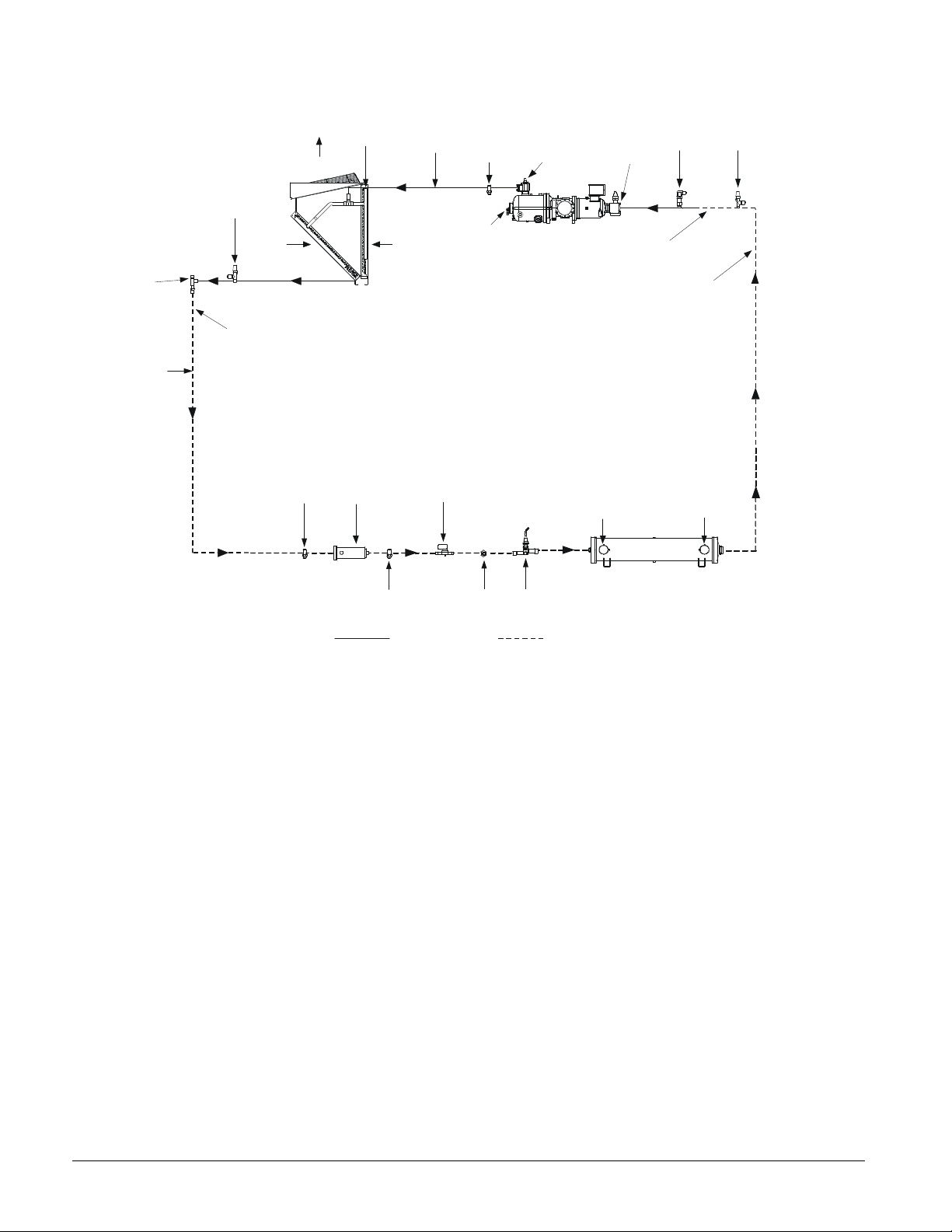
Figure 5, AGS-C Piping Schematic
WATER IN
DX EVAPORATOR
FIELD CONNECTION
SUCTION
SUCTION
CHARGING
330591001-R3
FACTORY PIPING
DISCHARGE
CHECK AND
SCHRADER
(HEADER)
AIR
FLOW
CHARGING
VALV E
AIR
LIQUID
SHUT-OFF
VALVE
LIQUID
TUBING
FLOW
FIELD CONNECTION
LIQUID LINE
VALVE
CONDENSOR
DISCHARGE
AIR
FLOW
ASSEMBLY
TUBING
SCHRADER
VALVE
RELIEF
VALVE
SHUT-OFF
VALVE
FRAME 3200
COMPRESSOR
SHUT-OFF
VALVE
SUCTION LINE
RELIEF
VALVE
VALVE
TUBING
SCHRADER
VALVE
FILTER
DRIER
SCHRADER
VALVE
SOLENOID
VALVE
SIGHT
GLASS
EXPANSION
VALVE
WATER OUT
FIELD PIPING
NOTE: The above figure illustrates the piping for the remote evaporator option. For the standard packaged
version, the field piping shown as dotted would be installed in the factory.
16 OM AGSC-11
Page 17
Control Operation
This section on MicroTech II control is divided into three subsections:
• Unit Controller, explains the functions of the unit controller, see page 17.
• Circuit Controller, explains the functions of the circuit controller, see page 29
• Using the Controller, explains how to navigate through the menus and how to make
entries, see page 48.
Unit Controller
Inputs/Outputs
Analog Inputs
The following parameters are analog inputs to this controller. They are used internally as
needed and are sent via the pLAN to other control devices.
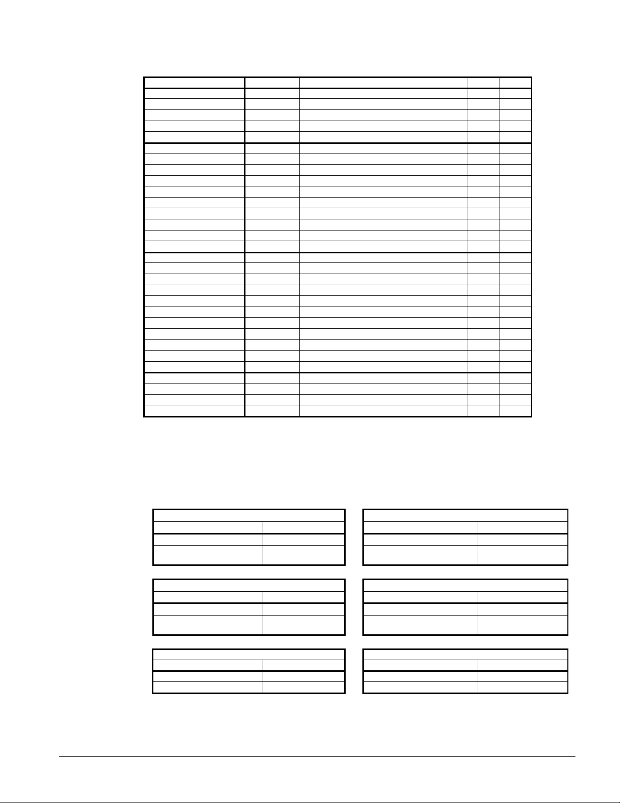
Table 1, Unit Analog Inputs
# Description Signal Source Range
1 Outdoor Ambient Temperature Thermister (10k@25°C) -58 to 212°F
2 Demand Limit 4-20 mA Current, External 0 to 100% limit
3 Chilled Water Reset 4-20 mA Current, External 0 to max reset
4 Leaving Evaporator Water Temperature Thermister (10k@25°C) -58 to 212°F
5 Entering Evaporator Water Temperature Thermister (10k@25°C) -58 to 212°F
Analog Outputs
Table 2, Unit Analog Outputs
# Description Output Signal Range
1 Open -- --
2 Open -- --
3 Open -- --
4 Open -- --
Digital Inputs
Table 3, Unit Digital Inputs
# Description Signal Signal
1 Unit Switch 0 VAC (Stop) 24 VAC (On)
2 Remote Switch 0 VAC (Stop) 24 VAC (Start)
3 Evaporator Water Flow Switch 0 VAC (No Flow) 24 VAC (Flow)
4 Mode Switch 0 VAC (Cool) 24 VAC (Ice)
5 Open -- --
6 Open -- --
7 Open -- --
8 Open -- --
OM AGSC-11 17
Page 18
Digital Outputs
Table 4, Unit Digital Outputs
# Description Output OFF Output ON
1 Evaporator Water Pump 1 Pump OFF Pump ON
2 Evaporator Water Pump 2 Pump OFF Pump ON
3 Open
4 Open
5 Open
6 Open
7 Open
8 Alarm No alarm Stop alarm
Setpoints
The following parameters are remembered during power off, are factory set to the Default
value, and can be adjusted to any value in the Range column.
The Type column defines whether the setpoint is part of a coordinated set of duplicate
setpoints in different controllers. There are two possibilities as given below:
N = Normal setpoint - Not copied from, or copied to, any other controller
M = Master setpoint - Setpoint is copied to all controllers in the “Sent To” column
The PW (password) column indicates the required password level.
Codes are as follows:
O = Operator, Password is 100 M = Manager
Toggle: Setpoints that have two choices, such as ON and OFF are toggled between the two
settings using the Up or Down keys on the controller.
NOTE: in some software versions the terms “inhibit” and “hold” are used interchangeably.
Table 5, Unit Setpoints
Description Default Range Type PW
UNIT
Unit Enable OFF OFF, ON N O
Unit Mode Cool Cool, Ice, Test M O
Control source Switches Switches, Keypad, Network N O
Available Modes Cool
Cool LWT
Ice LWT
Startup Delta T
Stop Delta T
Stage Up Delta T
Stage Down Delta T
Max Pulldown
Evap Recirc Timer 30 0 to 300 seconds N M
Evap Pump Select #1 Only #1 Only, #2 Only, Auto N M
LWT Reset Type NONE NONE, RETURN, 4-20mA, OAT N M
Max Reset
Start Reset Delta T
Soft Load Off Off, On N M
Begin Capacity Limit 40% 20-100% N M
Soft Load Ramp 20 min 1-60 minutes N M
Demand Limit Off Off, On N M
Low Ambient Lockout
Ice Time Delay 12 1-23 hours N M
Clear Ice Timer No No,Yes N M
Remote Evaporator No No, Yes M M
Quiet Night Disabled Disabled, Enabled N M
Quiet Night Start Time 21:00 18:00 - 23:59 N M
Cool, Cool w/Glycol, Cool/Ice w/Glycol, ICE
44°F 25(40) to 60°F
25°F 20 to 38°F
10°F 0 to 10°F
1.5°F 0 to 3°F
2°F 0 to 3°F
1°F 0 to 3°F
5 °F/min 0.5-5.0°F /min
0°F 0 to 20°F
10 °F 0 to 20°F
55°F 0(35) to 70°F
N M
N O
N O
M O
M O
M O
M O
M M
N M
N M
N M
Continued on next page.
18 OM AGSC-11
Page 19
Recirculate Timeout
3 min 1 to 10 min
N M
35 to 70
°F
150 to 200
°F
Unit Setpoints, Continued
Description Default Range Type PW
Quiet Night End Tme 6:00 5:00 – 9:59 N M
Quiet Night Cond Offset
BAS Protocol Modbus BACnet, LONW
Ident number 1 0-200 N M
Baud Rate 19200 1200,2400,4800,9600,19200 N M
COMPRESSORS
Sequence # Cir 1 1 1-2 M M
Sequence # Cir 2 1 1-2 M M
Start-start timer 20 min 15-60 minutes M M
Stop-start timer 5 min 3-20 minutes M M
Pumpdown Pressure 25 psi 10 to 40 psi M M
Pumpdown Time Limit 120 sec 0 to 180 sec M M
Light Load Stg Dn Point 25% 20 to 50% M M
Stage Up Delay 5 min 0 to 60 min M M
Disc Temp Sensor Type PT 1000 NTC, PT 1000 (see note) M M
ALARMS
Low Evap PressureLow Evap PressureLow Oil Level Delay 120 sec 10-180 sec M M
High Oil Press Diff Delay 15 sec 0-90 sec M M
High Discharge
High Lift Pressure Delay 5 sec 0 to 30 sec M M
Evaporator Water
Evaporator Flow Proof 15 sec 5 to 15 sec N M
Startup Timer 60 sec 20 to 180 sec M M
10.0°F 0.0 to 25.0°F
ORKS
, Modbus N M
28 psi 0(26) to 45 psi M M
30 psi 0(28) to 45 psi M M
200°F
36°F 15(36) to 42°F
150 to 200 F M M
N N
N M
SENSORS
Evap LWT sensor offset 0 -5.0 to 5.0 deg N M
Evap EWT sensor offset 0 -5.0 to 5.0 deg N M
OAT sensor offset 0 -5.0 to 5.0 deg N M
NOTE: AGS-C vintage can have either PT1000 or NTC sensors. If an NTC sensor is used with a control setting of
PT1000, the unit will not run because the discharge temperature displayed will be above the allowable operating
temperature and a fault will occur. However, if a PT1000 sensor is used with a control setting of NTC, an unsafe
operating condition exists since the sensor will show the temperature as decreasing, while it is increasing .
Auto-Adjusted Ranges
Some settings have different ranges that are automatically adjusted, based on other settings.
Table 6, Auto Adjusted Ranges
Cool LWT Evaporator Water Freeze
Mode Range Mode Range
Unit Mode = Cool
Unit Mode = Cool w/Glycol
40 to 60°F
25 to 60°F
Low Evaporator Pressure Inhibit Low Evaporator Pressure Unload
Mode Range Mode Range
Unit Mode = Cool 28 to 45 Psig Unit Mode = Cool 26 to 45 Psig
Unit Mode = Cool w/Glycol,
Ice w/ Glycol
0 to 45 Psig
Low Ambient Lockout
Fan VFD Enable Range
= No for All Circuits
= Yes for Any Circuit
-10 to 70°F
It is critical that the chiller system has sufficient anti-freeze to support the settings entered
for freeze-up protection. The glycol freeze or burst temperature must be at least 10
degrees F below the freeze-up setpoint.
Unit Mode = Cool
Unit Mode = Cool w/Glycol,
Ice w/ Glycol
Unit Mode = Cool w/Glycol,
Ice w/ Glycol
High Discharge Temperature
Discharge Temp Type Range
NTC
PT 1000
36 to 42°F
10 to 42°F
0 to 45 Psig
150 to 230°F
OM AGSC-11 19
Page 20
Unit Controller Functions
Parameter Definitions
LWT Slope
LWT slope is calculated so that the slope represents the change in LWT over a time frame of
one minute and is used to help determine the slide valve target.
Every 12 seconds, the current LWT is subtracted from the value 12 seconds back. This value
is added to a buffer containing values calculated at the last five 12-second intervals. The
final result is a slope value that represents the action of the LWT for the past 60 seconds.
Unit Capacity
Unit capacity is estimated based on the slide target of each running circuit. The capacity of a
running circuit is estimated with this equation:
Circuit capacity = 0.8(slide target) + 20
A circuit that is off is assumed to be at 0% capacity. The unit capacity is then calculated by
this equation:
Unit capacity = (Circuit 1 capacity + Circuit 2 capacity)/2
Unit Enable
Enabling and disabling the chiller is controlled by the Unit Enable Setpoint, with options of
OFF and ON. Enabling allows the unit to start if there is a call for cooling and also starts the
evaporator pump.
This setpoint (in other words, enabling the unit to run) can be altered by the Unit OFF input
(unit On/Off switch), a field installed remote stop switch, a keypad entry, or a BAS request.
The Control Source Setpoint determines which sources can change the Unit Enable Setpoint
with options of SWITCHES, KEYPAD or NETWORK.
Changing the Unit Enable Setpoint can be accomplished according to the following table.
NOTE: An “x” indicates that the value is ignored.
Table 7, Enable Sources
Unit On/Off
Switch
OFF x x x x OFF
On/OFF SWITCHES OFF x x OFF
ON SWITCHES ON x x ON
ON KEYPAD x OFF x OFF
ON KEYPAD x ON x ON
ON NETWORK x x OFF OFF
ON NETWORK OFF x x OFF
ON NETWORK ON x ON ON
NOTE: An “x” indicates that the value is ignored.
Control
Source
Setpoint
Remote
Stop
Switch
Key-pad
Entry
BAS
Request
Unit
Enable
Example:
1. If the Control Source is set to Switches, the field-installed remote Stop Switch controls
enabling. If the unit-mounted On/Off switch is either On or Off, the unit will be disabled
if the remote switch is Off. If the unit-mounted On/Off switch is On, the unit will be
enabled if the remote switch is On.
2. With the unit-mounted switch On, if the Control Source is Network, and the BAS signal
is Off, the unit is not enabled. If a Remote Switch is Off, the unit is not enabled. If a
Remote Switch is ON and the BAS input is On, the unit will be enabled.
20 OM AGSC-11
Page 21

Chiller Control Source Options:
Set Unit Setpoints Screen #1 (shown below) has three fields: “Enable”, “Mode” and
“Source.”
Unit Setpoints
SET UNIT SPs (1)
Enable=On
Mode= COOL
Source = KEYPAD
1. The Enable field can only be used with Source = Keypad. To enable and disable the
chiller through the keypad, any other control inputs including unit and pumpdown
switches and BAS controls are ignored. The Enable field toggles between On and Off.
2. The Mode field is an informational display, showing the active control mode of the
chiller. It is used as an input only when the source is set to keypad. Only then can this
field be changed manually.
3. The Source field has three options, “SWITCHES”(default), “KEYPAD”, and “BAS
NETWORK”.
a. Switches source is used when there is no BAS interface used. This allows the unit
switches to function as pumpdown and shutdown switches for the circuit. This
option is used with applications using the remote start/stop input and not using a
BAS interface.
b. Keypad source is used to override BAS or remote start/stop commands. This would
be used for servicing only.
c. BAS Network source would be used for those applications using “MODBUS”,
“BACnet”, or “LON” communications through a building automation system. BAS
Protocol is set at Set Unit Setpoints item #14.
All methods of disabling the chiller, except for the unit switch, will cause a normal
pumpdown shutdown of any running circuits. Any time the unit switch is used to disable the
chiller, all running circuits will shut down immediately, without pumping down.
Shutdown by the unit switch without going through the pumpdown cycle is undesirable and
should only be used for an emergency shutdown or for manually and locally disabling the
unit after both circuits have gone through a normal shutdown.
Unit Mode Selection
The overall operating mode of the chiller is set by the Unit Mode setpoint with options of
COOL, ICE and TEST. This setpoint can be altered by the keypad, BAS, and Mode input.
Changes to the Unit Mode Setpoint are controlled by two additional setpoints.
• Available Modes setpoint: usually set during initial setup and determines the operational
modes available at any time with options of:
• COOL, cooling only operation, with setpoints available for normal chilled water
temperatures
• COOL w/Glycol, cooling only operation, allows lower setpoints than COOL
• COOL/ICE w/Glycol, allows both cooling and ice mode operation, switchable by a
field installed remote ICE mode switch, by the network (BAS) or locally through the
keypad.
• ICE w/Glycol, ice mode only, i.e., full load operation until LWT setpoint is reached
• TEST
OM AGSC-11 21
Page 22
• Control Source Setpoint: The setting determines the source that can change the Unit
Mode Setpoint with options of KEYPAD, NETWORK, or SWITCHES.
When the Control source is set to KEYPAD, the Unit Mode stays at its previous setting until
changed by the operator. When the Control source is set to BAS, the most recent BAS mode
request goes into effect, even if it changed while the Control source was set to KEYPAD or
DIGITAL INPUTS.
Changing the Unit Mode Setpoint can be accomplished according to the following table.
NOTE: An “x” indicates that the value is ignored.
Table 8, Unit Mode Setpoint Sources
Control Source
Setpoint
x x x x COOL COOL
x x x x COOL w/Glycol COOL w/Glycol
SWITCHES OFF x x COOL/ICE w/Glycol COOL w/Glycol
SWITCHES ON x x COOL/ICE w/Glycol ICE w/Glycol
KEYPAD x COOL w/Glycol x COOL/ICE w/Glycol COOL w/Glycol
KEYPAD x ICE w/Glycol x COOL/ICE w/Glycol ICE w/Glycol
NETWORK x x COOL COOL/ICE w/Glycol COOL w/Glycol
NETWORK x x ICE COOL/ICE w/Glycol ICE w/Glycol
x x x x ICE w/Glycol ICE w/Glycol
x x x x TEST TEST
Remote
ICE Mode
Switch
Keypad Entry BAS Request
Available Modes
Setpoint
Resultant Unit
Mode
The Remote ICE Mode Switch (usually a time clock) is a field installed option and is used to
switch from ice mode operation at night to cooling mode operation during the day. This
requires that the Control Source be set to SWITCHES, which in this case refers to the
Remote ICE Mode Switch.
There are really only three operational modes for the unit, although they can be used in
combination:
1. COOL, the unit unloading and compressor staging is controlled by the Active LWT
Setpoint. COOL w/ Glycol is a special case of this mode, providing for lower setpoint
ranges.
2. ICE, the unit runs with all compressors fully loaded until the LWT (set for making ice) is
reached, and the unit shuts off. The Ice Delay Timer can be set to prevent restarting until
the next ice making cycle.
3. TEST, manually energize outputs for service testing.
Unit Test Mode
The unit test mode allows manual testing of controller outputs. Entering this mode requires
the following conditions.
• Unit OFF input = OFF (i.e. entire chiller is shut down).
• Technician password active.
• Available Circuit Mode setpoint = TEST
A test menu can then be selected to allow activation of the outputs. It is possible to switch
each digital output ON or OFF and set the analog outputs to any value.
22 OM AGSC-11
Page 23
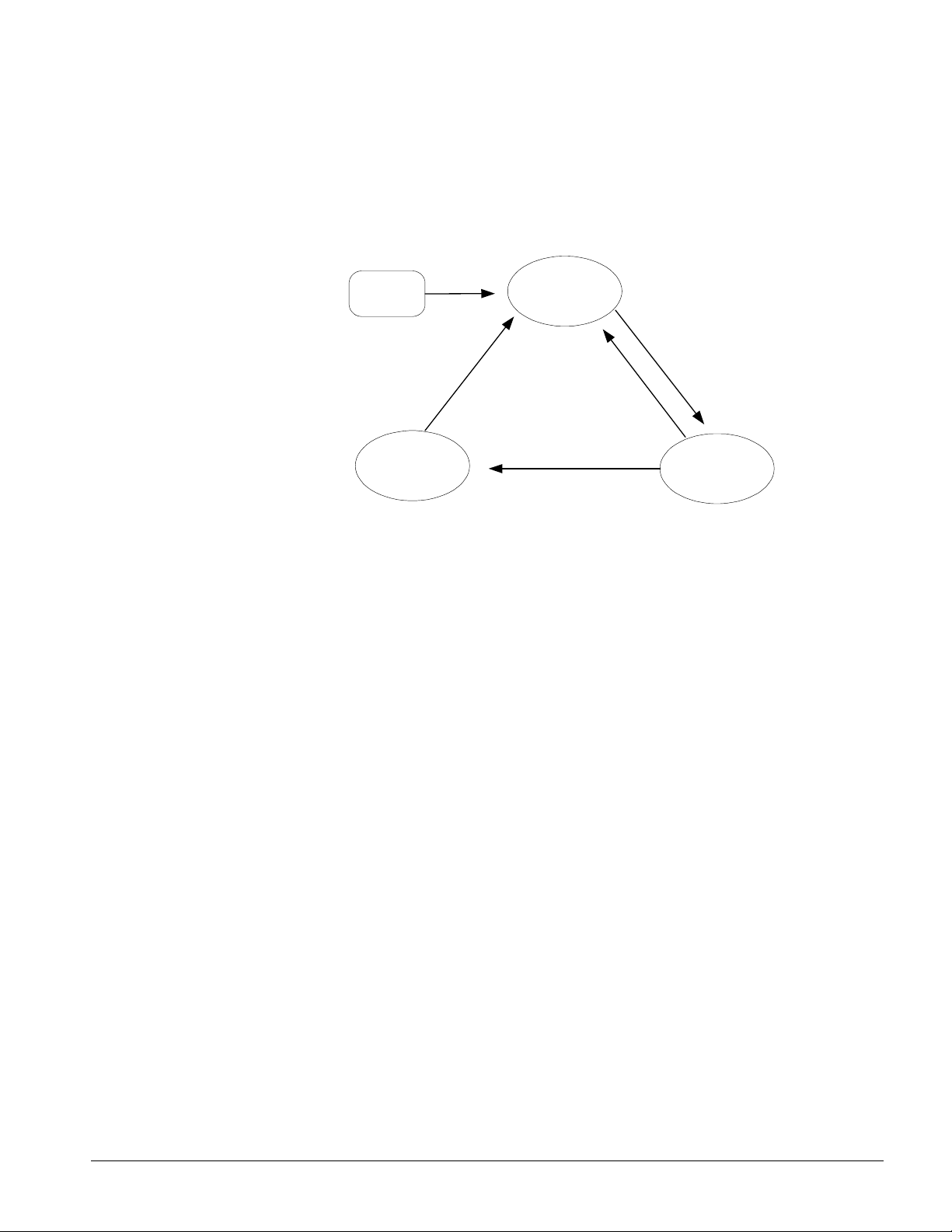
Unit States
The unit will always be in one of three states. Transitions between these states occur as
shown below.
Unit States
Power ON
T3
PUMPDOWN
OFF
T1
T4
T2
AUTO
Transitions:
T1 – Transition from Off to Auto requires all of the following:
• Unit enabled based on settings and switches.
• If unit mode is ice, the ice timer has expired
• No unit alarms exist.
• At least one circuit is enabled and available to start.
T2 – Transition from Auto to Pumpdown requires any of the following:
• Control source is keypad and the unit enable keypad setting is Off.
• Control source is BAS and either the remote switch is Off or the BAS command is Off
• Control source is switches and the remote switch is Off
T3 – Transition from Pumpdown to Off requires any of the following:
• All circuits have finished pumpdown and are Off.
• A unit alarm is active.
• Unit switch is Off.
T4 – Transition from Auto to Off requires any of the following:
• Unit switch is Off.
• A unit alarm is active.
• All circuits are unavailable to start (cannot start even after any cycle timers have
expired).
• The unit mode is ice, all circuits are Off, and the ice mode delay is active.
OM AGSC-11 23
Page 24
Ice Mode Start Delay
An adjustable start-to-start Ice Time Delay limits the frequency with which the chiller may
start in Ice mode. The timer starts when the first compressor starts while the unit is in ICE
mode. While this timer is active, the chiller cannot restart in ICE mode. The time delay is
user adjustable from 1 to 23 hours.
The ice delay timer may be manually cleared to force a restart in ice mode. The Clear Ice
Timer setpoint is specifically for clearing the ICE mode delay. In addition, cycling the
power to the controller will clear the ice delay timer.
Evaporator Pump Control
Operation of the evaporator pump is controlled by the state-transition diagram shown below.
Figure 6, Evaporator Pump States
Evaporator Pump
States
Power ON
T3
RUN
OFF
T1
T4
T2
START
T5
Transitions:
T1 – Transition from Off to Start requires any of the following:
• Unit state = Auto AND If Low OAT Lockout is active then LWT <= 40 °F
• LWT < Freeze setpoint - 1
T2 – Transition from Start to Run:
• Flow OK for time > evaporator recirculate time
T3 – Transition from Run to Off requires any of the following:
• Unit state = Off AND LWT > Freeze setpoint
• Low OAT Lockout is in effect AND No compressors running AND LWT > 70°F
T4 – Transition from Start to Off requires all of the following:
• Unit state = Off AND LWT > Freeze set point
• LWT > Freeze setpoint + 1
T5 – Transition from Run to Start
• Evaporator flow input low AND Evaporator state = Run for time greater than Flow Proof
set point
Pump selection
The pump output used will be determined by the Evap Pump Control set point. This setting
allows the following configurations:
24 OM AGSC-11
Page 25

#1 only – Pump 1 will always be used
#2 only – Pump 2 will always be used
Auto – The primary pump is the one with the least run hours, the other is used as a backup
#1 Primary – Pump 1 is used normally, with pump 2 as a backup
#2 Primary – Pump 2 is used normally, with pump 1 as a backup
Primary/Standby Pump Staging
The pump designated as primary will start first. If the evaporator state is Start for a time
greater than the recirculate timeout set point and there is no flow, then the primary pump will
shut off and the standby pump will start. When the evaporator is in the Run state, if flow is
lost for more than half of the flow proof set point, the primary pump will shut off and the
standby pump will start. Once the standby pump is started, the flow loss alarm logic will
apply if flow cannot be established in the evaporator start state, or if flow is lost in the
evaporator run state.
Auto Control
If auto pump control is selected, the primary/standby logic above is still used. When the
evaporator is not in the run state, the run hours of the pumps will be compared. The pump
with the least hours will be designated as the primary at this time.
Leaving Water Temperature (LWT) Reset
It is often desirable to raise (reset) the LWT setpoint to reduce unit energy consumption.
The Active Leaving Water variable (setpoint value) is normally set to the current Leaving
Water Temperature (LWT) setpoint, unless the unit is in COOL mode and any of the reset
methods shown below are selected and in effect. Reset is not available when in the ICE
mode.
The type of reset in effect is determined by the LWT Reset Type setpoint. The Active
Leaving Water variable is sent from the unit controller to all circuits for capacity control after
the applicable reset is applied.
Reset Type – NONE
The Active Leaving Water variable is set equal to the current LWT setpoint.
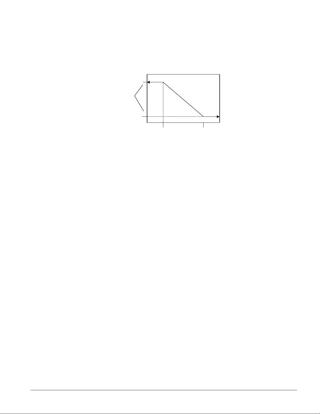
Reset Type – RETURN
The Active Leaving Water variable is adjusted by the return water temperature.
Figure 7, Return Water Reset
Return Reset
LWT set Point+Max Reset
(54)
Active
LWT
(oF)
Max Reset
(10)
LWT Set Point
(44)
0
Start Reset Delta T
Evap Delta T (oF)
OM AGSC-11 25
Page 26

The active setpoint is reset using the following parameters:
1. Cool LWT setpoint
2. Max Reset setpoint
3. Start Reset Delta T setpoint
4. Evap Delta T
Reset is accomplished within the controller by changing the Active Leaving Water variable
from the Cool LWT setpoint to the Cool LWT set-point + Max Reset setpoint as the
Evaporator EWT – LWT (Evap Delta T) varies from the Start Reset Delta T set-point to 0.
Referring to Figure 7 as an example, the LWT is 44°F and a 10-degree maximum reset value
was selected. In other words, the Active LWT setpoint would range from the normal 44°F
setting up to 54°F depending on the Evap Delta-T. The amount of reset would be at the
maximum value (10 degrees) when the Evap Delta-T is zero and at the minimum value when
the Evap Delta-T is at the Start Reset Delta T value and is proportional in between. The Start
Reset Delta T function is available so that the start of reset can be adjusted. For example, on
a system with a 10-degree Delta-T, it may be desirable to not start the resetting until the
evaporator Delta-T goes down to eight degrees (80% load), or some other value.
Reset Type – 4-20 mA
The Active Leaving Water variable is adjusted by the 4 to 20 mA reset analog input.
Parameters used:
1. Cool LWT setpoint
2. Max Reset setpoint
3. LWT Reset signal
Reset is 0 if the reset signal is less than or equal to 4 mA. Reset is equal to the Max Reset
Delta T setpoint if the reset signal equals or exceeds 20 mA. The amount of reset will vary
linearly between these extremes if the reset signal is between 4 mA and 20 mA. An example
of the operation of 4-20 reset in Cool mode is shown below.
Figure 8, 4-20 mA Remote Reset Signal
4-20 mA Reset - Cool Mode
(54)
Active
LWT
(oF)
Max Reset
(10)
Cool LWT Set
Point (44)
0
4
Reset Signal (mA)
20
Reset Type – OAT
The Active Leaving Water variable is reset based on the outdoor ambient temperature (OAT).
Parameters used:
1. Cool LWT setpoint
2. Max Reset setpoint
3. OAT
26 OM AGSC-11
Page 27
Reset is 0 if the outdoor ambient temperature is greater than 75°F. From 75°F down to 60°F
the reset varies linearly from no reset to the max reset at 60°F. At ambient temperatures less
than 60°F, reset is equal to the Max Reset setpoint.
Figure 9, Outside Air Reset
OAT Reset
Cool LWT+Max Reset
(54)
Active
LWT
(oF)
Max Reset
(10)
Cool LWT Set-Point
(44)
60
OAT (oF)
75
Unit Capacity Overrides
Unit capacity limits can be used to limit total unit capacity in COOL mode only. Multiple
limits may be active at any time, and the lowest limit is always used in the compressor
capacity control.
The estimated unit capacity and the active capacity limit are sent to all circuits for use in
compressor capacity control.
Soft Load
Soft Loading is a configurable function used to ramp up the unit capacity over a given time,
usually to influence building electrical demand by gradually loading the unit. The setpoints
that control this function are:
• Soft Load – (ON/OFF)
• Begin Capacity Limit – (Unit % load at start)
• Soft Load Ramp – (1 to 60 minutes))
The Soft Load Unit Limit increases linearly from the Begin Capacity Limit set-point to
100%, over the amount of time specified by the Soft Load Ramp set-point. If the option is
turned off, the soft load limit is set to 100%.
Demand Limit
The maximum unit capacity can be limited by a 4 to 20 mA signal wired to the Demand
Limit terminals, 70 and 71 on TB1. This function is only enabled if the Demand Limit
setpoint is set to ON.
As the signal varies from 4 mA up to 20 mA, the maximum unit capacity changes linearly
from 100% to 0%. Although the demand limit can call for 0% capacity, this signal will never
cause a running compressor to shut down. Rather, all running compressors will be held at
minimum load, and this may occur at a demand limit value that is actually less than 20mA.
OM AGSC-11 27
Page 28

Network (BAS) Limit
The maximum unit capacity can be limited by a network signal. This function is only
enabled if the unit control source is set to NETWORK. The signal will be received through
the BAS interface on the unit controller.
As the signal varies from 0% up to 100%, the maximum unit capacity changes linearly from
0% to 100%. Although the network limit can call for 0% capacity, this signal will never
cause a running compressor to shut down. Rather, all running compressors will be held at
minimum load, and this may occur at a network limit value that is actually less than more
than 0%.
Building Automation System Interface
Connection to Chiller
Connection to the chiller for all BAS protocols will be at the unit controller. An interface
card (communication module) will have been installed in the unit controller at the factory, if
so ordered, or the module can be field installed after unit installation. The specific module
will depend on the protocol being used. Setting is made in Set Unit Setpoints, menu 14.
Additional information can be found in the following manuals:
LONW
ORKS –
BACnet – ED 15062 Modbus – ED 15063
IM 735 BACnet – IM 736 Modbus – IM 743
Quiet Night Operation
Logic has been added to limit unit capacity and fans running during nighttime hours.
• Settings were added to enable or disable this logic, set the start and end times, and set the
condenser target offset.
• Quiet Night operation is in effect if it is enabled via the set point, the unit is running in
cool mode, and the unit time is between the start and end time settings.
• When Quiet Night is in effect, the maximum LWT reset will be applied. This is to limit
the capacity of the compressors. In addition, the circuits will offset their condenser
targets up. Depending on conditions, this can result in less fans running and/or the VFD
running at a lower speed.
• The unit status will indicate when Quiet Night is in effect (assuming no overriding status
is active).
•
The Quiet Night reset will be overridden by any other reset source (4-20mA, return
water, OAT).
28 OM AGSC-11
Page 29

Circuit Controller
Inputs/Outputs
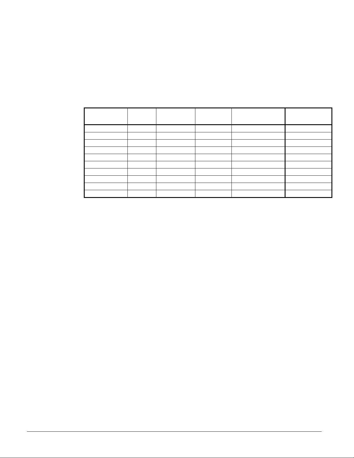
Table 9, Analog Inputs
# Description Signal Source Range
1 Evaporator Pressure 0.5 – 4.5 V DC (See Note)
2 Condense r Pressure 0.5 – 4. 5 VDC (See Not e)
3 Open
4 Suction Temperature NTC Thermister (10k@25°C ) -58 to 212°F
5 Discharg e Tem perature NTC Thermister (10k@ 25°C) -58 to 212°F
6 Open
7 Slide Lo ad Indicator 4 to 20 mA
8 Open
NOTE: Value at the converter board input. Value at the converter board output is 0.1 VDC – 0.9 VDC.
These parameters are analog inputs to the circuit controller. They are used internally as
needed and are sent to the correct pLAN addresses for use by other controllers or displays.
Table 10, Analog Outputs
# Description Output Signal Range
1 Fan VFD 0 to 10 VDC 0 to 100%
2 Open
3 EXV Driver 0 to 10 VDC 0 to 6386 steps
4 Open
0 to 132 psi
3.6 to 410 psi
0 to 100%
Table 11, Digital Inputs
# Description Signal Signal
1 Circuit Switch 0 VAC (Off) 24 VAC (Auto)
2 Open
3 Open
4 VFD Fault 0 VAC (Fault) 24 VAC (No Fault)
5 Oil Differential Pressure Switch 0 VAC (Fault) 24 VAC (No Fault)
6 Mechanical High Pressure Switch 0 VAC (Fault) 24 VAC (No Fault)
7 Mechanical Low Pressure Switch (1) Fault No Fault
7 Open
8 Open
9 Oil Level Sensor 0 VAC (Fault) 24 VAC (No Fault)
10-14 Open
NOTE (1) With remote evaporator, this alarm will trigger with low pressure after 40 second compressor run time.
The status of digital inputs may be viewed on Circuit Status screen 5, on the circuit
controllers only.
Table 12, Digital Outputs
# Description Output OFF Output ON
1 Fan 1 Contactor Fan off Fan on
2 Fan 2 Contactor Fan off Fan on
3 Fan 3 Contactor Fan off Fan on
4 Fan 4 Contactor Fan off Fan on
5 Fan 5 Contactor Fan off Fan on
6 Fan 6 Contactor Fan off Fan on
7 Load/Unload Pulse Hold load slide Move load slide
8 Load/Unload Select Unload Load
9 Compressor SSS Contact Compressor off Compressor on
Continued next page
OM AGSC-11 29
Page 30

# Description Output OFF Output ON
10 Open
11 Oil Heater Heater off Heater on
12 Economizer Models 180, 190, 210, 195, 161 Economizer off Economizer on
13 EXV Close Signal
EXV follows
0 -10 VDC
EXV closed, ignores 0 –
10 VDC
Setpoints
The following parameters are remembered during power off, are factory set to the Default
value, and can be adjusted to any value in the Range column.
The PW (password) column indicates the password level that must be active in order to
change the setpoint. Codes are as follows:
O = Operator, password is 100, M = Manager,
Entering a Password
The password can be found at SET, UNIT SPS on the last menu, conveniently located so that
you can scroll up one menu to access the Password Enter Screen.
Table 13, Circuit Controller Setpoints
Description Default Range PW
COMPRESSOR
1 Clear Cycle Timers No No, Yes M
2 Compressor Size 167 167, 179, 197 M
3 Maximum Slide Target (Note 3) 100.0 0-100.0% M
4 Circuit mode Enable Disable, Enable, Test M
5 Slide target 0 0-100 M
6 Slide control Auto Auto, Manual M
7 Motor FLA (See Table 14) 1 to 341 amps M
8 Motor RLA (See Table 14) 1 to 341 amps M
9 Ground Fault Enable Disable Enable, Disable M
10 Ground Fault Trip Level 1 0 to 100% M
11 Full Load Amps 10 amps 1 to 9999 amps M
12 Service Factor 125% 100 to 199% M
13 Ground Fault Enable Disable Disable/Enable M
14 Ground Fault Trip Level 1% 1 to 100% M
15 Overload Class 10 0 to 40 M
16 Initial Motor Current 225% 50 - 400% FLA M
17 Maximum Motor Current 300% 100 - 800% FLA M
18 Ramp Time 7 seconds 0 - 300 seconds M
19 Up To Speed Time 10 seconds 1 - 900 seconds M
20 Stop Mode CoS
21 Rated RMS Voltage 460 volts 100 to 1000 volts M
22 Over voltage Trip Level 10% 1 - 40% rated volts M
23 Under voltage Trip Level 10% 1 - 40% rated volts M
24 Ovr/Undr Volt Trip Delay 1.0 seconds 0.1 - 90.0 seconds M
25 Current Imbalance Trip Level 15% 5 - 40% M
26 Auto fault Reset Time 60 seconds 0 - 120 seconds M
27 CT Ratio 864:1 72 – 8000:1 M
EXV
1 Manual EXV position 0 0-6386 M
2 EXV control Auto Auto, Manual M
3 Service Pumpdown No No, Yes M
Continued next page
Coast(CoS)
Voltage Decel (dcL)
M
30 OM AGSC-11
Page 31

Description Default Range PW
FANS
1 Number of fans 4 4 to 6 M
2 Fan VFD On Off, On M
Stage 2 On Dead band (Note 2)
3
(Stage 1 On Dead band)
Stage 3 On Dead band
4
(Stage 2 On Dead band)
Stage 4 On Dead band
5
(Stage 3 On Dead band)
Stage 5 On Dead band
6
(Stage 4 On Dead band)
7 Stage 2 Off Dead band 8.0 (20.0)
8 Stage 3 Off Dead band 7.0 (16.0)
9 Stage 4 Off Dead band 6.0 (11.0)
10 Stage 5 Off Dead band 5.0 (8.0)
11 VFD Min Speed 25% 20 to 60% M
12 VFD Max Speed 100% 90 to 110% M
Saturated Condenser Temp
13
Target Max
Saturated Condenser Temp
14
Target Min
15
Forced FanTrol 1
16
Forced FanTrol 2
17
Forced FanTrol 3
SENSORS (Note 1)
1 Evap pressure offset 0 -10.0 to 10.0 psi M
2 Cond pressure offset 0 -10.0 to 10.0 psi M
3 Suction temp offset 0 -5.0 to 5.0 deg M
4 Discharge temp offset 0 -5.0 to 5.0 deg M
5 Slide Minimum Position Offset 0 -15 to 15% M
6 Slide Maximum Position Offset 0 -15 to 15% M
5.0
(8.0)
8.0
(10.0)
10.0
(11.0)
8.0 (12.0)
110.0
85.0
2 1 to 4 M
3 1 to 4 M
4 1 to 4 M
1.0-20.0°F
1.0-20.0°F
1.0-20.0°F
1.0-20.0°F
1.0-20.0°F
1.0-20.0°F
1.0-20.0°F
1.0-20.0°F
90.0-120.0°F
80.0-110.0°F
M
M
M
M
M
M
M
M
M
M
Notes:
1. Offsets are used to fine-tune certain readings generated by sensors. For example, if the controller was
showing a 125 psi value and a calibrated pressure gauge at the same location showed 127 psi, an offset of +2
psi would be entered and the controller would then read the corrected value of 127 psi.
2. VFD staging is shown in entries without parenthesis. FanTrol staging is shown in parenthesis.
3. Slide target information is explained on page 37.
Table 14, FLA/RLA Values
Compressor 575V 460V 380V 230V 208V 400V (50Hz)
RLA Without Economizer (Models 120, 130, 140, 160, 170, 125, 135, 145, 165, 175)
197
179
167
197
All
113 141 178 282 312 141
94 122 145 240 267 122
85 112 128 210 232 112
RLA With Economizer (Models 190, 195, 210)
123 154 187 308 340 154
FLA (All Models)
113 141 178 282 312 141
Dynamic Default Values
The fan staging dead bands have different default values based on the VFD enable setpoint.
When the VFD enable setpoint is changed, a set of default values for the fan staging dead
bands is loaded in accordance with the following table:
OM AGSC-11 31
Page 32

Figure 10, VFD Dynamic Default Values
VFD is Enabled VFD is Disabled
Setpoint Default loaded (oF) Setpoint Default loaded (oF)
Stage 2 On Dead band 5 Stage 1 On Dead band 8
Stage 3 On Dead band 8 Stage 2 On Dead band 10
Stage 4 On Dead band 10 Stage 3 On Dead band 11
Stage 5 On Dead band 8 Stage 4 On Dead band 12
Stage 2 Off Dead band 8 Stage 2 Off Dead band 20
Stage 3 Off Dead band 7 Stage 3 Off Dead band 16
Stage 4 Off Dead band 6 Stage 4 Off Dead band 11
Stage 5 Off Dead band 5 Stage 5 Off Dead band 8
Circuit Controller Functions
Refrigerant Calculations
Refrigerant Saturated Temperature
Refrigerant saturated temperature is calculated from the pressure sensor readings for each
circuit. The pressure will be fitted to a curve made up of 12 straight-line segments. The
points used to define these segments are shown in the following tables.
Table 15, Evaporator Pressure Conversion:
Pressure (PSI) Temperature (oF)
0 -15.0
7.1 0
19.0 20.0
34.7 39.0
50.7 54.0
70.4 69.0
99.6 87.0
129.2 102.0
166.8 118.0
205.4 132.0
246.5 145.0
320.0 165.0
428.5 188.1
Table 16, Condenser Pressure Conversion:
Pressure (PSI) Temperature (oF)
0 0.6
17.5 18.5
31.5 35.9
50.0 53.7
76.0 73.4
115.0 95.6
161.5 116.2
185.0 125.2
260.0 149.2
284.5 155.9
349.5 172.0
365.5 175.5
428.5 188.1
32 OM AGSC-11
Page 33

Circuit Operating Mode
The circuits on the chiller can each be individually enable or disabled with an ON or OFF for
the Unit Enable setting. Test mode on each circuit can also be entered independent of all
other circuits. With the circuit switch on, the circuit mode setpoint offers settings of either
enable, disable, or test. This simply allows the circuit to be disabled through a keypad
setting.
ICE Mode
Ice mode is designed to have the compressors run at full load until the LWT setpoint is
reached, then shut off until the next ice making cycle starts. ICE settings are made in the
unit controller.
In ICE mode, the compressor capacity is increased at the maximum rate continuously until
reaching the maximum slide position. Load balancing, LWT error, and LWT slope are
ignored. Low and high pressure events are disabled.
An adjustable Start-to-Start Ice Delay Timer will limit the frequency with which the chiller
may start in ICE mode. The timer starts when the first compressor starts while the unit is in
ICE mode. While this timer is active, the chiller cannot restart in ICE mode. The time delay
is user adjustable from 1 to 23 hours.
The Ice Delay Timer may be manually cleared to force a restart in ICE mode. A setpoint
specifically for clearing the ICE mode delay (Clear ICE Timer) is available. In addition,
cycling the power to the controller will clear the Ice Delay Timer.
Circuit Test Mode
The circuit test mode allows manual testing of all controller outputs. Entering this mode
requires the following conditions.
• Circuit Switch = OFF
• Technician password active
• Circuit Mode setpoint = TEST
A test menu can then be selected to allow activation of the outputs. It is possible to switch
each digital output ON or OFF and set the analog outputs to any value. Upon entering the
test mode, all outputs will always default to the OFF state. Upon leaving the test mode, all
outputs will automatically reset to the OFF state.
Compressors cannot be started in TEST mode.
Compressor Control
Multiple Compressor Staging
This section defines which compressor is the next one to start or stop. Unless programmed
otherwise, compressors with fewer starts will start first, and compressors with more run
hours will stop first.
Functions
• Can start/stop compressors according to an operator-defined sequence.
• Can start compressors based on # of starts (run hours if starts are equal) and stop on run
hours.
• The above two modes can be combined, so that there are two or more groups, where all
compressors in the first group are started (based on number of starts/hours) before any in
the second group, etc. Conversely, all compressors in a group are stopped (based on run
hours) before any in the preceding group, etc.
These setpoints are a unit function and are programmed in the unit controller.
OM AGSC-11 33
Page 34

Starting
A compressor should be started when all of the following are true:
• Number of compressors running =0
• LWT Error > Startup Delta T SP
The second compressor should be started when all of the following are true:
• Number of compressors running = 1
• Running compressor is running at full load
• LWT Error > Stage Up Delta T SP
• Stage Up Delay is not active
• Max Compressors On set point = 2
Stopping
A compressor should shut off when all of the following are true:
• Number of compressors running > 1
• LWT Error < -(Stage Down Delta T SP)
A compressor should shut off when all of the following are true:
• Number of compressors running > 1
• Running compressors are running with slide position < light load stagedown set point
• LWT Error < Stage Up Delta SP
A compressor should shut off when all of the following are true:
• Number of compressors running = 1
• LWT Error < -(Stop Delta T SP)
Multiple Compressor Start/Stop Timing – Cool Mode
This section defines when a compressor is to start or stop when in Cool mode. The settings
are located in the unit controller.
Settings (made in the set setpoint section of the unit controller0
• Startup Delta-T setpoint (for starting the first compressor)
• Stageon Delta-T setpoint (for starting the second compressor)
• Stop Delta-T setpoint (for stopping the last compressor running)
• Stageoff-Delta-T setpoint (for stopping the second compressor)
The first compressor will start when:
LWT > LW setpoint + Startup Delta-T
The second compressor will start when:
LWT > LW setpoint + Stageon Delta-T and the Stageon Timer times out
The second compressor will stop when:
LWT < LW setpoint – Stageoff Delta-T
The last compressor will stop when:
LWT < LW setpoint – Stop Delta-T
The first compressor must be fully loaded before the second will start, unless something is
preventing it from fully loading such as:
• Slide control = manual
• A low or high pressure limit event has been active for 10 seconds
In other words, if there is a call for cooling and the first compressor is being prevented
from achieving full load, the second compressor will start.
• Slide target has been reached, max slide position setting
34 OM AGSC-11
Page 35

Multiple Compressor Start/Stop Timing – Ice Mode
Stopping and starting when in the ICE Mode is based solely on the LWT setpoint.
The first compressor starts when the LWT is greater than the ICE setpoint plus the Startup
Delta-T. The second compressor starts when the LWT is greater than the ICE setpoint plus
the Stageon Delta-T and the staging timer has expired.
They both run at full load until the ICE mode setpoint (in unit controller) is reached, then
shut off. The ICE Time Delay (a start-to-start timer that is usually set at 12 hours) prevents
frequent restarting when the LWT rises a little while still in the ICE mode.
Compressor Capacity Control
Slide Position is a relative capacity adjustment from 0.0%(Min load) to 100.0%(Max Load).
There are two MicroTech II controller readings that apply to the indicator, Slide Target and
Slide Position. It is important to understand the difference between these. The Slide Target
is the value in which the controller uses to display the calculated prediction of slide position,
this value represents the destination or goal of pulsing the load and unload solenoid coils.
The slide target is used for direction of control for all load and unload operations, including
alarm limit events. When putting a circuit in Manual mode, the slide target is the value that
you will be adjusting. The controller will load or unload the chiller to match, with in about
3%, the target entered with the current slide position value. The second value is the Slide
Position (Pos) this is the slide position value which is the 4-20mA reading received from the
position indicator. These values can be viewed at the circuit controller on screen “VIEW
CIR STATUS (1)”.
A slide target of 0.0% is fully unloaded and the unload solenoid will be constantly energized.
A slide target of 100.0% means that the chiller is at full load and the load solenoid is
continually energized. The chiller will regulate the slide position to infinite steps between
0% and 100% by pulsing the appropriate solenoid. Facing the discharge end of the
compressor, looking along the left side, the solenoid coil on the top is for load (oil vent) and
the solenoid coil on the side is for unload (oil feed). During normal operation, the controller
makes decisions to move the Slide target, the calculated value, and pulses the proper
solenoid in order to keep the actual and the target position with in a few percent.
Low discharge superheat will unload the compressor. If the circuit is running and the low
pressure inhibit event is active, the compressor will unload when the discharge superheat
drops below 20 degrees. The unloading will occur by adjusting the slide target down by 2%
every 10 seconds.
Compressor capacity is determined by calculating a slide position target, which is the slide
position required for the compressor to load, or unload, sufficiently to meet the load.
Adjustment to the slide target for normal running conditions occurs every 5 seconds. For
loading, a maximum change of 1% is allowed, and for unloading, a maximum change of 2%
is allowed. The compressors signal the controller the position of the slide valve.
The circuit controller determines the slide target (where the slide valve should be) based on a
number of inputs such as:
• the actual water temperature compared to LWT setpoint (LWT Error)
• the LWT Slope (how fast is the LWT changing in the last 60 seconds)
• the load condition of slope the other compressor, if it is running, for load balance
considerations
• other parameters that can affect loading such as Max Pulldown Rate and an external
Load Limit signal listed on page 36.
If the slide valve is not at the slide target (within a 6% dead band), the controller pulses the
slide valve solenoid to reposition the valve to the target.
OM AGSC-11 35
Page 36

Cool Mode
When the chiller is in COOL mode, capacity of the compressor is adjusted to maintain
leaving water temperature at the Active LWT setpoint while balancing the load between
running circuits.
Ice Mode
In ICE mode, the compressor capacity is increased at the maximum rate continuously until
reaching the maximum slide position. Load balancing, LWT error, and LWT slope are
ignored. The unit shuts off when the LWT setpoint is reached.
Low Outdoor Air Temperature (OAT) Start Logic
In order to avoid low pressure alarms at the start of a circuit during low outdoor tempeatures,
low OAT start logic allows for running at low pressures for a longer time than normal, and
allows for multiple start attempts.
A low OAT start is initiated if the condenser saturated temperature is less than 60°F when the
compressor starts. Once this happens, the circuit is in this low OAT start state for a time
equal to the Startup Timer setpoint (in unit controller). During this time, the freezestat logic
and the low pressure events are disabled. The absolute limit of –10 psi suction pressure is
still enforced.
At the end of the low OAT start, the evaporator pressure is checked. If the pressure is greater
than, or equal to, the low evaporator pressure unload setpoint (see below), the start is
considered successful. If the pressure is less than the unload setpoint, the start is not
successful and the compressor will stop. Three start attempts are allowed before tripping on
the restart alarm; so if on the third attempt the start is not successful, the restart alarm is
triggered.
The restart counter is reset when either a start is successful or the circuit is off on an alarm.
Capacity Overrides – Limits of Operation
The following conditions will override the automatic slide control when the chiller is in
COOL mode or ICE mode. These overrides keep the circuit from entering a condition in
which it is not designed to run. Any compressor running with capacity limits because of
these conditions is considered to be at full load in the compressor staging logic.
External Load Limit
The capacity can be limited by keyboard entry, by a BAS or by an external 4-20 ma signal.
Low Evaporator Pressure
If the compressor is running and the evaporator pressure drops below the Low Evaporator
Pressure-Hold setpoint (unit controller), the compressor will not be allowed to increase
capacity. This limit is active until the evaporator pressure reaches the hold setpoint + 2 psi.
If the compressor is running above minimum load capacity and the evaporator pressure drops
below the Low Evaporator Pressure-Unload setpoint, the compressor will begin reducing
capacity. The slide target will be adjusted down 5% every 5 seconds until the evaporator
pressure rises above the Low Evaporator Pressure-Unload setpoint. The compressor is then
not allowed to increase capacity until the Hold event clears.
High Lift Pressure
If the compressor is running and the condenser pressure rises above the High Lift Pressure
Hold setpoint, the compressor will not be allowed to increase capacity. This limit will be
active until the condenser pressure drops 10 psi below the hold setpoint.
If the compressor is running above minimum load capacity and the condenser pressure rises
above the High Condenser Pressure Unload setpoint, the compressor will begin reducing
capacity. The slide target will be adjusted down 5% every 5 seconds until the condenser
pressure drops below the High Condenser Pressure-Unload setpoint. The compressor is not
allowed to increase capacity until the condenser pressure is more than 10 psi below the
unload setpoint.
36 OM AGSC-11
Page 37

Low Discharge Superheat Unload
Low discharge superheat will unload the compressor. If the circuit is running and the low
pressure inhibit event is active, the compressor will unload when the discharge superheat
drops below 20 degrees. The unloading will occur by adjusting the slide target down by 2%
every 10 seconds.
Maximum LWT Pulldown Rate
The maximum rate at which the leaving water temperature can drop is limited by the
Maximum Rate setpoint, only when the LWT is less than 60oF. Above 60°F, a rapid
pulldown is desired. A slope unload factor is used to reduce the slide target if the pulldown
rate exceeds the Maximum Rate setpoint. The setpoint is in the unit controller set setpoints
section and set as °F/min.
Slope Unload Factor: Maximum Rate + LWT slope
If the pulldown rate is too fast, the slide adjustment made will be equal to the slope unload
factor.
High Water Temperature Capacity Limit
If the evaporator LWT exceeds 65°F, compressor slide position is limited to a maximum of
75%. Compressors will unload to 75% or less if running at greater than 75% slide position
when the LWT exceeds the limit. This feature is to keep the circuit running within the
capacity of the condenser coil.
Unit Capacity Overrides
Unit capacity limits override the automatic slide control when the chiller is in COOL mode
only. The active capacity limit, as well as the estimated unit capacity, will be calculated in
the unit controller and sent to all circuits.
If the unit capacity is greater than the active capacity limit, then no circuit will increase slide
position. If the unit capacity is greater than the active limit plus 1%, the circuits will unload
until the unit capacity is less than 1% greater than the active limit.
Pumpdown
Normal Pumpdown
When a circuit reaches a condition where the compressor needs to shut down normally, a
pumpdown will be performed. The slide target will automatically go to 0 while pumping
down, and the compressor will run until the pumpdown pressure has been reached, or the
pumpdown time has been exceeded.
Service Pumpdown
If the option for a service pumpdown is enabled, then on the next pumpdown the pressure
setpoint will be 5 psi. The circuit will pumpdown to this pressure and shut off. When the
compressor has completed the service pumpdown, the setpoint is reset to NO.
Slide Positioning
Slide Position Indicator
Each compressor estimates its slide load percentage from the present value of the slide
position indicator. The percentage is based on the 4-20mA signal from the slide load
indicator. A percentage value of 0 corresponds to approximately a 4mA signal; a percentage
value of 100 corresponds to approximately a 20mA signal.
AGS-C Slide Calibration Procedure
Slide Position is a relative capacity adjustment from 0.0%(Min load) to 100.0%(Max Load).
There are two MicroTech readings that apply to the indicator, Slide Target and Slide
Position. It is important to understand the difference between these. The Slide Target is the
OM AGSC-11 37
Page 38

value in which the controller uses to display the calculated prediction of slide position, this
value represents the destination or goal of pulsing the load and unload solenoid coils. The
slide target is used for direction of control for all load and unload operations, including alarm
limit events. When putting a circuit in Manual mode, the slide target is the value that you
will be adjusting. The controller will load or unload the chiller to match, with in about 3%,
the target entered with the current slide position value. The second value is the Slide
Position (Pos) this is the slide position value which is the 4-20mA reading received from the
position indicator. These values can be viewed at the circuit controller on screen “VIEW
CIR STATUS (1)”.
A slide target of 0.0% is fully unloaded and the unload solenoid will be constantly energized.
A slide target of 100.0% means that the chiller is at full load and the load solenoid is
continually energized. The chiller will regulate the slide position to infinite steps between
0% and 100% by pulsing the appropriate solenoid. Facing the discharge end of the
compressor, looking along the left side, the solenoid coil on the top is for load (oil vent) and
the solenoid coil on the side is for unload (oil feed). During normal operation, the controller
makes decisions to move the Slide target, the calculated value, and pulses the proper
solenoid in order to keep the actual and the target position with in a few percent.
Figure 11, Slide Indicator and Coils Locations
Load Coil
Unload Coil
Slide Indicator
Calibration Procedure:
1. The circuit to be calibrated should be near normal operating temperatures. Note that the
compressor requires sufficient oil pressure to unload the compressor while it is running,
and may load up due to lack of oil feed pressure.
2. On the Circuit controller, first verify what your current slide target is at screen “View
Circ Status (1)” and then go to screen “SET COMP SPs (2)” to switch circuit into
manual slide control. Note: Some hold limits will be ignored but all alarm limits are
still active while in manual slide control.
3. Slowly take the circuit to 0% slide position. When the slide target is at 0%, verify that
the unload coil is energized.
4. Find the slide indicator device located on the left side of the compressor facing the
discharge end. Unscrew the metal cap and press the calibrate button beside the LED.
The red LED will come on for about 30 seconds and then start to blink. The indicator is
now calibrated at 0%.
5. Now, slowly take the circuit to 100% slide position, watching that the suction pressure
and other unit readings are OK. Always keep discharge superheat above 22°F. When
the slide target is at 100%, verify that the load coil is energized. Press the calibrate
button. The red LED will come on for about 30 seconds and then the green LED will
come on. The indicator is now calibrated at 100%.
6. The mechanical calibration is now complete for the compressor you are working with.
Replace the calibration cap.
38 OM AGSC-11
Page 39

7. Once you have the mechanical slide calibration complete you may fine tune the
calibration from the circuit controller, if necessary. On the circuit controller scroll all the
way to the right, this is the calibration and offsets menu. Scroll down until you see “SET
SENSOR OFFSET(3)”. You will see an adjustment for Min Load and Max Load and on
the bottom line you will see the value of actual slide position indicator. Add offset until
value is within +/-.5% of the corresponding full load or minimum load position.
8. Repeat calibration procedure until all circuits have min and max positions calibrated.
Note: The Slide Indicator Transducers may vary a considerable amount with temperature
change, and therefore they need to be calibrated at typical running temperatures.
Slide Pulse
The slide pulse output moves the compressor slide in order to reach the capacity requested
by the slide position target. The output will pulse for 200 ms every 6 seconds while the Slide
Pulse flag is true, that is, whenever there is a difference between the actual slide position and
the requested position.
Manual Slide Control Mode
The slide position on each circuit can be controlled manually. A setting on the compressor
setpoints screen in each circuit controller allows the operator to select manual slide control.
On the same screen, a slide target can be selected, from 0% to 100%.
Anytime a circuit is in manual slide control, it is considered to be at full load in the staging
logic. It also will not be considered in load balancing calculations. None of the capacity
limits outlined above will apply in manual slide control, but all stop alarms are still
applicable.
Slide control will revert back to automatic control if a stop alarm occurs on the circuit or
unit, or the slide control has been manual for four hours.
Expansion Valve (EXV) Control
The EXV can be in any of three states (or control modes) as explained below. The EXV
state is determined by parameters shown in Figure 12. The valve has thousands of steps, or
positions, that it will take depending on factors as explained below.
Pressure Control
In pressure control, the evaporator pressure is controlled by the EXV position. The pressure
target varies based on evaporator LWT and discharge superheat values. A proportionalintegral-derivative (PID) logic is used to control the pressure to the target value.
The base pressure target is calculated using the following formula:
Base target = 0.6(LWT) – 2
The base target is limited to a range from the low pressure inhibit setpoint plus 2 psi, up to
52 psi.
The pressure control target may be adjusted if the discharge superheat is not within an
acceptable range. If the superheat is less than 22°F, the base pressure target will be reduced
by a value equal to the low superheat error. If the superheat is more than 40°F, the base
pressure target will be increased by a value equal to the high superheat error. At any time,
the adjusted target pressure cannot go below the low pressure inhibit setpoint or above 52
psi.
When the EXV transitions to the pressure control state, the target will start at the current
evaporator pressure value. The pressure target will then decrement 0.2 psi every second until
reaching the normal calculated target. If the pressure at transition is less than the calculated
target, then pressure control will start immediately with the calculated target.
OM AGSC-11 39
Page 40

Superheat Control
In superheat control, suction superheat is controlled directly by the EXV. The superheat
target varies linearly from 6 to 10°F as discharge superheat changes from 30°F to 22°F. PID
logic is used to control the superheat to the target value.
When the EXV transitions to the superheat control state, the target will start at the current
suction superheat value. This target will then decrement 0.1 degree F every second until
reaching the normal target.
Closed
Any time the EXV is not in pressure control or superheat control, it will be in a closed state.
At this time, the EXV position is 0 steps and the EXV close signal (digital output) is active.
The following exceptions exist:
• Pre-open logic has been added to open the EXV prior to starting the compressor,
allowing it to be in a better position at start-up. The solenoid valve remains closed.
• After the compressor pumps down and shuts off, the EXV will re-open for 30
seconds to prevent hydraulic lock between the solenoid valve and expansion valve
EXV State Transitions
The EXV state is determined by parameters illustrated in the following Figure 12.
Figure 12, EXV Transition
EXV States
Closed
Superheat
T2
T3
Power ON
T1T4T5
Pressure
EXV Transitions:
T1 – Transition from Closed to Pressure Control requires all of the following:
• Unit State = Auto
• Evap State = Run
• Compressor is available
• Compressor is next on
• Stage up now flag is set
• Compressor State = Off
T2 – Transition from Pressure Control to Superheat Control requires all of the following:
• Suction Superheat >= Superheat target
• Evap LWT <= 60°F
• EXV State = Pressure AND Discharge Superheat >= 22°F for at least 3 minutes
• Discharge Temperature <= 180°F
T3 – Transition from Superheat Control to Pressure Control requires any of the following:
• Evap LWT > 63°F
• Low Evap Pressure Unload event active
• Discharge Superheat < 22°F
• Discharge Temperature > 185°F
40 OM AGSC-11
Page 41

T4, T5 – Transition from any state to Closed state requires the following:
• Compressor in Pumpdown
• Compressor shut down
EXV Control Range
The table below shows the EXV range of steps (positions) for each size compressor, at
minimum and maximum capacity, as determined by the slide position. The minimum and
maximum values vary linearly with slide position, defining a new EXV control range for
every change in slide position. Thus, the range of EXV steps allowed (minimum and
maximum step) increases as the load increases and more refrigerant flow is required. The
minimum and maximum opening also increases as the compressor size, and its capacity and
motor cooling requirement, increases.
Table 17, EXV Control Range
EXV Slide %
Min 0 250 250 250
Max 0 3000 3000 3000
Min 100 870 1080 1300
Max 100 3400 4200 5000
167 179 197
Based on the values in the above table, the EXV control range varies as shown in the figure
below. The shaded area the control range. The control range considers factors such as
providing sufficient refrigerant flow for motor cooling and preventing liquid flood-back.
Compressor Size
Figure 13, Control Range
EXV Control Range
Max EXV
@ 100%
EXV
Steps
Max EXV
@ 0%
Min EXV
@ 100%
Min EXV
@ 0%
0
Slide Position (%)
100
Manual EXV Control
The EXV position can be set manually. Manual control can only be selected when the
compressor is in the run state. At any other time, the EXV control setpoint is forced to auto.
When EXV control is set to manual, the EXV position is equal to the manual EXV position
setting. If set to manual when the compressor state transitions from run to another state, the
control setting is automatically set back to auto.
Oil Heater Control
The oil heater is on when the compressor is not running and the oil level input is closed for
15 seconds. This output will turn off immediately when either the oil level switch opens or
the compressor state is no longer OFF.
OM AGSC-11 41
Page 42

Economizer Control
An economizer is provided on selected units (Models 180, 190, 195, 210, and 161) and is
activated when the circuit state is Run and the compressor’s slide position indicator exceeds
95%. It turns off when the circuit goes to a state other than Run, or the slide position drops
below 60%. Under certain conditions, an economizer can improve system efficiency by
subcooling the refrigerant being fed to the evaporator.
The liquid refrigerant flow from the condenser flows through one side of a brazed-plate heat
exchanger (the economizer). A side stream of the liquid refrigerant flows through an
expansion valve to the other side of the brazed plate exchanger where it evaporates at
interstage pressure. The saturated temperature at this pressure is considerably lower than the
saturated condensing temperature. This lower temperature refrigerant cools the main stream
of refrigerant before it enters the evaporator, reducing its enthalpy and increasing the
refrigerant capacity of every pound of refrigerant circulated.
Figure 14, Economizer Piping
To
Evaporator
To
Compressor
Interstage
EXV
SV
Economizer
TXV
SV
SV
Filter
Drier
Solinoid
Valve
Ball
Valve
Legend
From
Condenser
EXV
Electronic
Expansion
Valve
TXV
Thermal
Expansion
Valve
42
OM AGSC-11
Page 43

Starter Communications
The Modbus protocol is used to establish communications between the circuit controller and
the compressor starter using a serial card in the serial port, with the circuit controller acting
as the master and the starter as the slave.
The starter and the circuit controller exchange information concerning starting, faults,
current, voltage, power factor, and kW.
Table 18, Parameters to be Read/Written:
Register Description R/W Range Units
1020 Starter Control R/W
1021 Starter Status R
1026 Avg Current R Amps
1027 L1 Current R Amps
1028 L2 Current R Amps
1029 L3 Current R Amps
1032 Avg Voltage R Volts
1033 L1-L2 Voltage R Volts
Bit Mask
0: Run/Stop 1: Fault Reset
Bit Mask
0: Ready 1: Running
2: UTS 3: Alarm
4: Fault 5: Lockout
-
-
1034 L2-L3 Voltage R Volts
1035 L3-L1 Voltage R Volts
1037 PF R
1038 KW R KW
1039 KVA R KVA
1045 Motor FLA R/W 1-9999 Amps
1046 Motor RLA R/W 1-9999 Amps
1057
1058 Ground Fault Trip Level R/W 1-100 % RLA
1078
Ground Fault Trip
Enable
Fault Code – Most
Recent Fault Log Entry
R/W 0: Disabled 1: Enabled -
R -
-99 to 100 (in 16 bit two’s
compliment signed format)
0.01
Read-only parameters are displayed at the circuit controller, and sent over pLAN to the unit
controller where they will also be displayed. Read/write parameters are accessible at the
circuit controller only. These read/write parameters are changeable when the starter
communication is working and the proper password is active.
Starter Faults
Starter faults are viewed from unit controller. Some starter faults will be implemented as
unique alarms, and all others will be grouped into a generic starter fault alarm. The most
recent fault code shall be stored in the alarm log parameter list. The fault reset signal is sent
to the starter when the operator clears the active alarm on the unit controller.
OM AGSC-11
The starter fault codes and their corresponding alarms are shown in the table below: These
faults are displayed on the starter three-character LED display. See IMM AGS-2 for details.
43
Page 44

Table 19, Starter Faults
Internal
Fault Code
00 No Fault N/a
01 Up to Speed (UTS) Time Limit Expired No Starter Transition
02 Motor Thermal Overload Trip Compressor Current Overload Trip
10 Phase Rotation Error, not ABC Phase Reversal
12 Low Line Frequency (Hz) Starter Fault
13 High Line Frequency (Hz) Starter Fault
15 Input power not three phase Phase Loss
21 Low Line L1-L2 Voltage Undervoltage
22 Low Line L2-L3 Voltage Undervoltage
23 Low Line L3-L1 Voltage Undervoltage
24 High Line L1-L2 Voltage Overvoltage
25 High Line L2-L3 Voltage Overvoltage
26 High Line L3-L1 Voltage Overvoltage
27 Phase Loss Phase Loss
28 No Line Voltage Undervoltage
30 Instantaneous Overcurrent Compressor Current Overload Trip
31 Overcurrent Compressor Current Overload Trip
37 Current Imbalance Motor Current Imbalance
38 Ground Fault Ground Fault Protection
39 No Current at Run Low Motor Current
40 Shorted/Open SCR Starter Fault
47 SCR Stack Protection Fault Starter Fault
48 Bypass Contactor Fault (on Stop Input) No Starter Transition
50 Control Power Low Starter Fault
51 Current Sensor Offset Error Starter Fault
52 Burden Switch Error Starter Fault
60 Thermistor Trip High Motor Temperature
61 SCR Stack OT Switch Trip Starter Fault
71 Analog Input Trip Starter Fault
82 Modbus Timeout Starter Fault (detected by circuit controller)
94 CPU Error – Software Fault Starter Fault
95 CPU Error – Parameter Storage Fault Starter Fault
96 CPU Error – Illegal Instruction Trap Starter Fault
97 CPU Error – Software Watchdog Fault Starter Fault
98 CPU Error – Spurious Attempt Starter Fault
99 CPU Error – Program Storage Fault Starter Fault
Starter Fault Description Alarm Triggered
If a starter fault is active and the active alarms are cleared at the unit controller, the clear
alarm signal will also be sent to the starter to clear the alarm status in the starter. If the fault
condition is still true, the alarm will return.
Starter Communications
This software version changes starter communication so that starter communication is not
required in order to run a circuit. When starter communication is functioning, the power data
coming from the starter will be displayed and if starter faults occur, the alarm descriptions
will better indicate the actual problem. Also, the starter fault code for starter faults is
displayed in the alarm log. If a starter fault occurs while communication is not functional,
this fault code will simply show ’00’ in the alarm log.
44
OM AGSC-11
Page 45

Some starter faults are auto clearing in the starter itself. The alarms triggered by these faults
have been set up to allow auto clearing the first two occurrences each day. The third
occurrence will be a manual reset alarm. Since the third occurrence is a manual reset alarm,
the only way to clear it is via the active alarm screens on the unit controller. The alarms that
use this logic include:
Current Imbalance Current Low Phase Loss
Phase Reversal Voltage High Voltage Low
No Starter Transition Starter Fault (catch-all for faults not otherwise classified)
The generic Starter Fault alarm can be triggered if a starter fault that does not fit into a
specific category occurs. In addition, if a starter fault occurs while starter communications
are not working, the generic Starter Fault alarm will always be triggered since the starter
fault code cannot be read from the starter.
Some starter faults are never auto clearing in the starter. The alarms triggered by these faults
can be cleared either via the active alarm screens on the unit controller, or by clearing the
fault at the starter. The alarms triggered by these faults include the following:
High Current Trip High Motor Temperature Ground Fault
Condenser Fan Control
Optional VFD Low Ambient Control
This option is required for unit operation between 35°F and 0°F ambient air temperature.
Condenser pressure trim control is accomplished using an optional VFD on one fan. This
VFD control uses a proportional-integral function to drive the saturated condenser
temperature to a target value by changing the fan speed. The target value is normally the
same as the saturated condenser temperature target setpoint.
VFD State
The VFD will be started when all the following conditions are true:
• Compressor State is not Off.
• Fan VFD is enabled.
• Saturated Condenser Temp >= Saturated Condenser Temp Target.
• Fan speed output = 0.
OM AGSC-11
The VFD will be turned off when either of the following conditions is true:
• FanTrol fans on = 0 AND Fan speed output = min speed setpoint AND Condenser
Saturated Temp < 70oF
• Compressor State = Off
Stage Up Compensation
In order to create a smoother transition when another fan is staged on, the VFD compensates
by slowing down initially. This is accomplished by adding the new fan stage up dead band
to the VFD target. The higher target causes the VFD logic to decrease fan speed. Then,
every 5 seconds, 0.5oF is subtracted from the VFD target until it is equal to the saturated
condenser temperature target setpoint. This will allow the VFD to slowly bring the saturated
condenser temperature back down.
Standard FanTrol (Fan Staging Control)
Fan Stages Without VFD Option
If the VFD option is not enabled in the circuit controller’s set setpoints section, there are up
to 6 stages of FanTrol available. See the table below:
45
Page 46

Table 20, Fan Staging Without VFD
FanTrol Stage Fans On
1 1
2 1,2
3 1,2,3
4 1,2,3,4
5 1,2,4,5,6
6 1,2,3,4,5,6
Fan Stages With VFD Option
When the VFD option is enabled, the first fan is controlled by the fan VFD. This leaves up
to 5 stages of FanTrol available. See the table below:
Table 21, Fan Staging With VFD
FanTrol Stage Fans On
1 2
2 2,3
3 2,3,4
4 2,3,4,5
5 2,3,4,5,6
Staging Up
The controller looks at high the discharge pressure is and how quickly it is rising by
accumulating “points” in a collection bin called the “Stage Up Accumulator”.
There are four Stage Up dead bands that apply to the FanTrol stages. Stages one through
three use their respective dead bands. Stage four to six share the fourth Stage Up dead band.
When the saturated condenser temperature is above the Target + the active dead band, a
Stage Up error is accumulated.
Stage Up Error Step = Saturated Condenser Refrigerant Temperature – (Target + Stage
Up dead band)
The Stage Up Error Step is added to Stage Up Accumulator once every Stage Up Error Delay
seconds. When Stage Up Error Accumulator is greater than the Stage Up Error Setpoint
another stage is added.
If the pressure rises to a high level, the Stage Up Error will be large and a lot of “points” will
be added to the accumulator. A large rate of increase will be noted due to the timing element.
This method allows the discharge pressure to rise slowly and moderately without turning on
a fan. Ambient temperatures or the cooling load may drop in the interim, negating the need
for the next fan to start.
When a stage up occurs or the saturated condenser temperature falls back within the Stage
Up dead band the Stage Up Accumulator is reset to zero.
Forced Fan Stage At Start
Fans may be started simultaneously with the compressor based on outdoor ambient
temperature. When the compressor starts, a FanTrol stage is forced based on the following
table. Since this logic applies only to FanTrol fans, the VFD fan is not affected.
Table 22, Forced Fans at Startup
OAT FanTrol Stage At Start
> 75 oF Forced FanTrol 1 SP
> 90 oF Forced FanTrol 2 SP
> 105 oF Forced FanTrol 3 SP
46
OM AGSC-11
Page 47

Staging Down
There are four Stage Down dead bands. Stages one through three use their respective dead
bands. Stages four to six share the fourth Stage Down dead band.
When the saturated condenser refrigerant temperature is below the Target – the active dead
band, a Stage Down error is accumulated.
Stage Down Error Step = (Target - Stage Down dead band – Saturated Condenser
Refrigerant temperature
The Stage Down Error Step is added to Stage Down Accumulator once every Stage Down
Error Delay seconds. When the Stage Down Error Accumulator is greater than the Stage
Down Error Setpoint, another stage of condenser fans turned off.
When a stage down occurs, or the saturated temperature rises back within the Stage Down
dead band, the Stage Down Error Accumulator is reset to zero. The accumulator is also held
at zero after startup until either the outside ambient temperature is less than or equal to 75°F,
or the saturated condenser temperature is greater than the condenser target less the active
stage down dead band.
OM AGSC-11
47
Page 48

Alarms and Events
Situations may arise that require some action from the chiller or that should be logged for
future reference. A condition that causes a shutdown and requires manual reset is known as
a stop alarm. Other conditions can trigger what is known as an event, which may or may not
require an action in response. All stop alarms and events are logged.
Unit Stop Alarms
The alarm output and red button led shall be turned ON when any stop alarm occurs. They
shall be turned off when all alarms have been cleared.
Evaporator Flow Loss
Alarm description (as shown on screen): Evap Water Flow Loss
Trigger:
1: Evaporator Pump State = Run AND Evaporator Flow Digital Input = No Flow for time >
Flow Proof Set Point AND at least one compressor running
2: Evaporator Pump State = Start for time greater than Recirc Timeout Set Point and all
pumps have been tried
Action Taken: Rapid stop all circuits
Reset:
This alarm can be cleared at any time manually via the keypad or via the BAS clear alarm
signal.
If active via trigger condition 1:
When the alarm occurs due to this trigger, it can auto reset the first two times each day, with
the third occurrence being manual reset.
For the auto reset occurrences, the alarm will reset automatically when the evaporator state is
Run again. This means the alarm stays active while the unit waits for flow, then it goes
through the recirculation process after flow is detected. Once the recirculation is complete,
the evaporator goes to the Run state which will clear the alarm. After three occurrences, the
count of occurrences is reset and the cycle starts over if the manual reset flow loss alarm is
cleared.
If active via trigger condition 2:
If the flow loss alarm has occurred due to this trigger, it is always a manual reset alarm.
Evaporator Water Freeze Protect
Alarm description (as shown on screen): Evap Water Freeze
Trigger: Evaporator LWT drops below evaporator freeze protect set point AND Unit State =
Auto AND Evaporator LWT Sensor Fault not active
Action Taken: Rapid stop all circuits
Reset: This alarm can be cleared manually via the keypad or via the BAS clear alarm signal,
but only if the alarm trigger conditions no longer exist.
Leaving Evaporator Water Temperature Sensor Fault
Alarm description (as shown on screen): Evap LWT Sens Fault
Trigger: Sensor shorted or open
Action Taken: Rapid stop all circuits
Reset: This alarm can be cleared manually via the keypad, but only if the sensor is back in
range.
48
OM AGSC-11
Page 49

Outdoor Air Temperature Sensor Fault
Alarm description (as shown on screen): OAT Sensor Fault
Trigger: Sensor shorted or open
Action Taken: Rapid stop all circuits
Reset: This alarm can be cleared manually via the keypad, but only if the sensor is back in
range.
pLAN Failure
Alarm description (as shown on screen): pLAN Failure
Trigger: No circuit controllers found on pLAN for 60 seconds
Action Taken: Rapid stop all circuits
Reset: This alarm can be cleared manually via the keypad, but only if at least one circuit is
connected to pLAN.
Unit Events
The following unit events are logged in the event log with a time stamp.
Entering Evaporator Water Temperature Sensor Fault
Event description (as shown on screen): EWT Sens Fault
Trigger: Sensor shorted or open
Action Taken: Return water reset cannot be used.
Reset: Auto reset when sensor is back in range.
Circuit Stop Alarms
All circuit stop alarms require shutdown of the circuit on which they occur. Rapid stop
alarms do not do a pumpdown before shutting off. All other alarms will do a pumpdown.
The red button led on the circuit controller shall be turned on when any circuit stop alarm
occurs. It shall be turned off when all circuit alarms have been cleared. In addition, the
alarm status shall be sent to the unit control so the alarm output and the red button led on the
unit controller can be energized while alarms are active.
Alarm descriptions apply to both circuits, the circuit number is represented by ‘N’ in the
description.
Low Evaporator Pressure At Start
Alarm description (as shown on screen): LowPress StartFail N
Trigger: The saturated condenser temperature at start is equal to or greater than 70 °F AND
the circuit has failed a Start Logic attempt.
Action Taken: Rapid stop circuit
Reset: This alarm can be cleared manually via the Unit Controller keypad.
Low Evaporator Pressure
Alarm description (as shown on screen): Evap Press Low N
Trigger: [Freezestat trip AND Compressor State = Run AND Start Logic not active AND
Evap Pressure Sensor Fault not active] OR [Evaporator Press < -10 psi AND startup timer
complete AND Evap Pressure Sensor Fault not active]
Freezestat logic allows the circuit to run for varying times at low pressures. The lower the
pressure, the shorter the time the compressor can run. This time is calculated as follows:
Freeze error = Low Evaporator Pressure Unload – Evaporator Pressure
Freeze time = 70 – 6.25 x freeze error, limited to a range of 20-70 seconds
OM AGSC-11
49
Page 50

When the evaporator pressure goes below the Low Evaporator Pressure Unload set point, a
timer starts. If this timer exceeds the freeze time, then a freezestat trip occurs. If the
evaporator pressure rises to the unload set point or higher, and the freeze time has not been
exceeded, the timer will reset.
Action Taken: Rapid stop circuit
Reset: This alarm can be cleared manually via the Unit Controller keypad if the evaporator
pressure is above –10 psi.
High Lift Pressure
Alarm description (as shown on screen): Lift Pressure High N
Trigger: Condenser Saturated Temperature > Max Saturated Condenser Value for time >
High Lift Delay set point
Action Taken: Rapid stop circuit
Reset: This alarm can be cleared manually via the Unit Controller keypad.
Mechanical Low Pressure
Alarm description (as shown on screen): Mech Low Pressure N
Trigger: Mechanical Low Pressure switch input is low AND Remote Evap set point = yes
AND Circuit State = Run for longer than 20 seconds
Action Taken: Rapid stop circuit
Reset: This alarm can be cleared manually via the Unit Controller keypad.
Mechanical High Pressure
Alarm description (as shown on screen): Mech High Pressure N
Trigger: Mechanical High Pressure switch input is low
Action Taken: Rapid stop circuit
Reset: This alarm can be cleared manually via the Unit Controller keypad if the MHP switch
input is high.
High Discharge Temperature
Alarm description (as shown on screen): Disc Temp High N
Trigger: Discharge Temperature > High Discharge Temperature set point AND compressor
is running AND Discharge Temperature Sensor Fault is not active
Action Taken: Rapid stop circuit
Reset: This alarm can be cleared manually via the Unit Controller keypad.
Low Oil Level
Alarm description (as shown on screen): Oil Level Low N
Trigger: Oil Level Switch input is open for time greater than Low Oil Level Delay while
compressor is in the Run state AND the Low Oil Level Event has occurred in the past hour.
Action Taken: Rapid stop circuit
Reset: This alarm can be cleared manually via the Unit Controller keypad.
High Oil Pressure Difference
Alarm description (as shown on screen): Oil Pres Diff High N
Trigger: Oil DP switch input is low for time greater than High Oil Pressure Difference
Delay set point AND compressor is running
Action Taken: Rapid stop circuit
Reset: This alarm can be cleared manually via the Unit Controller keypad.
50
OM AGSC-11
Page 51

Low OAT Restart Fault
Alarm description (as shown on screen): LowOATRestart Fail N
Trigger: Circuit has failed three Start Logic attempts under Low Outside Ambient
Conditions (saturated condenser temperature at start is less than 70 °F)
Action Taken: Rapid stop circuit
Reset: This alarm can be cleared manually via the Unit Controller keypad.
No Pressure Change After Start
Alarm description (as shown on screen): NoPressChgAtStart N
Trigger: After start of compressor, either at least a 1 psi drop in evaporator pressure OR 5
psi rise in condenser pressure has not occurred after 15 seconds
Action Taken: Rapid stop circuit
Reset: This alarm can be cleared manually via the Unit Controller keypad.
No Pressure At Startup
Alarm description (as shown on screen): No Press At Start N
Trigger: [Evap Pressure < 5 psi OR Cond Pressure < 5 psi] AND Compressor start
requested AND VFD disabled
Action Taken: Rapid stop circuit
Reset: This alarm can be cleared manually via the Unit Controller keypad.
Starter Fault Alarms
If starter communication is operational and the starter fault input goes low, then the alarm
triggered will vary based on the fault code received from the starter. See the table below:
Alarm Description as shown on screen Code
Starter Fault
Current Overload Trip Current Overload N Code = 2, 30, or 31
Current Imbalance Current Imbalance N Code = 37
Low Motor Current Motor Current Low N Code = 39
High Motor Temperature Motor Temp High N Code = 60
Phase Loss Phase Loss Cir N Code = 15 or 27
Phase Reversal Phase Reversal Cir N Code = 10
Overvoltage Overvoltage Cir N Code = 24, 25, or 26
Undervoltage Undervoltage Cir N Code = 21, 22, 23, or 28
Ground Fault Protection Ground Fault Prot N Code = 38
No Starter Transition No Starter Trans N Code = 1 or 48
Some starter faults are auto clearing in the starter itself. The alarms triggered by these faults
will allow auto resetting the first two occurrences each day. The third occurrence will be a
manual reset alarm. The third occurrence is a manual reset alarm, and the only way to clear
it is via the active alarm screens on the unit controller. The alarms that use this logic
include:
Current Imbalance
Current Low
Phase Loss
Phase Reversal
Voltage High
Voltage Low
No Starter Transition
Starter Fault
Starter Fault N Code = Not listed below
OM AGSC-11
51
Page 52

Some starter faults are never auto clearing in the starter. The alarms triggered by these faults
can be cleared either via the keypad on the unit controller, or by clearing the fault manually
at the starter. The alarms triggered by these faults include the following:
High Current Trip
High Motor Temperature
Ground Fault
If starter communication is not operational and the starter fault input goes low, the Starter
Fault alarm is triggered for every alarm. The auto reset logic still applies to the Starter Fault
alarm in this case, but it applies to starter faults in general rather than specific starter faults
since there is no way to differentiate between starter faults without communication.
Evaporator Pressure Sensor Fault
Alarm description (as shown on screen): EvapPressSensFault N
Trigger: Sensor shorted or open
Action Taken: Rapid stop circuit
Reset: This alarm can be cleared manually via the keypad, but only if the sensor is back in
range.
Condenser Pressure Sensor Fault
Alarm description (as shown on screen): CondPressSensFault N
Trigger: Sensor shorted or open
Action Taken: Rapid stop circuit
Reset: This alarm can be cleared manually via the keypad, but only if the sensor is back in
range.
Suction Temperature Sensor Fault
Alarm description (as shown on screen): SuctTempSensFault N
Trigger: Sensor shorted or open
Action Taken: Rapid stop circuit
Reset: This alarm can be cleared manually via the keypad, but only if the sensor is back in
range.
Discharge Temperature Sensor Fault
Alarm description (as shown on screen): DiscTempSensFault N
Trigger: Sensor shorted or open
Action Taken: Rapid stop circuit
Reset: This alarm can be cleared manually via the keypad, but only if the sensor is back in
range.
Slide Position Sensor Fault
Alarm description (as shown on screen): Slide Pos Sens Fault N
Trigger: Sensor shorted or open AND Slide Control set to Auto
Action Taken: Rapid stop circuit
Reset: This alarm can be cleared manually via the keypad, but only if the sensor is back in
range or Slide Control is set to manual.
52
OM AGSC-11
Page 53

pLAN Failure
Alarm description (as shown on screen):
Trigger: pLAN communication with unit controller is lost
Action Taken: Rapid stop circuit
Reset: This alarm automatically resets when communication with the unit controller is
established. This alarm is not logged.
Circuit Events
The following events limit operation of the circuit in some way as described in the Action
Taken column. The occurrence of a circuit event only affects the circuit on which it
occurred. Circuit events are logged in the event log on the unit controller.
Low Evaporator Pressure - Hold
Event description (as shown on screen): EvapPress Low Hold N
Trigger: The low pressure events are not enabled until the compressor has started and the
evaporator pressure has risen above the Low Evaporator Pressure - Hold set point. The unit
mode must also be Cool. Then, while running, if evaporator pressure <= Low Evaporator
Pressure - Hold set point the event is triggered.
Action Taken: Inhibit loading by only allowing the slide target to be reduced.
Reset: While still running, the event will be reset if evaporator pressure > (Low Evaporator
Pressure - Hold SP + 2psi). The event is also reset if the unit mode is switched to Ice, or the
compressor state is no longer Run.
Low Evaporator Pressure - Unload
Event description (as shown on screen): EvapPressLowUnload N
Trigger: The low pressure events are not enabled until the compressor has started and the
evaporator pressure has risen above the Low Evaporator Pressure - Hold set point. The unit
mode must also be Cool. Then, while running, if evaporator pressure <= Low Evaporator
Pressure - Unload set point the event is triggered.
Action Taken: Unload the compressor by decreasing the slide target 5% every five seconds
until the evaporator pressure rises above the Low Evaporator Pressure – Unload set point.
Reset: While still running, the event will be reset if evaporator pressure > (Low Evaporator
Pressure - Hold SP + 2psi). The event is also reset if the unit mode is switched to Ice, or the
compressor state is no longer Run.
High Lift Pressure - Hold
Event description (as shown on screen): LiftPressHigh Hold N
Trigger: While the compressor is running and unit mode is Cool, if saturated condenser
temperature >= High Saturated Condenser - Hold Value, the event is triggered.
Action Taken: Inhibit loading by only allowing the slide target to be reduced.
Reset: While still running, the event will be reset if saturated condenser temperature < (High
Saturated Condenser - Hold Value – 10oF). The event is also reset if the unit mode is
switched to Ice, or the compressor state is no longer Run.
High Lift Pressure - Unload
Event description (as shown on screen): LiftPressHighUnloadN
Trigger: While the compressor is running and unit mode is Cool, if saturated condenser
temperature >= High Saturated Condenser - Unload Value, the event is triggered.
Action Taken: Unload the compressor by decreasing the slide target 5% every five seconds
until the condenser pressure drops below the High Saturated Condenser - Unload Value.
OM AGSC-11
53
Page 54

Reset: While still running, the event will be reset if saturated condenser temperature < (High
Saturated Condenser - Unload Value – 10oF). The event is also reset if the unit mode is
switched to Ice, or the compressor state is no longer Run.
Oil Level Low
Event description (as shown on screen): Oil Level Low Cir N
Trigger: Oil Level Switch input opens longer than Low Oil Level Delay while compressor
is in the Run state AND the Low Oil Level Event has not occurred in the past hour.
Action Taken: Rapid stop circuit
Reset: Compressor state = off
Failed Pumpdown
Event description (as shown on screen): Pumpdown Fail Cir N
Trigger: Circuit state = pumpdown for time > Pumpdown Time set point
Action Taken: Shutdown circuit
Reset: N/A
Power Loss While Running
Event description (as shown on screen): Run Power Loss Cir N
Trigger: Circuit controller is powered up after losing power while compressor was running
Action Taken: Delay start of compressor by time equal to the Start-Start timer set point.
Reset: N/A
VFD Fault
Event description (as shown on screen): VFD Fault Cir N
Trigger: VFD enabled and VFD fault input goes low
Action Taken: None
Reset: N/A
Slide Position Error
Event description (as shown on screen): Slide Pos Error Cir N
Trigger: Circuit state = run and the slide position indicator is not tracking within 25% of the
slide target for a period of 5 minutes.
Action Taken: None
Reset: N/A
Alarm Logging
When an alarm occurs, the alarm type, date, and time are stored in the active alarm buffer
corresponding to that alarm (viewed on the Alarm Active screens) and also in the alarm
history buffer (viewed on the Alarm Log screens). The active alarm buffers hold a record of
all current alarms. The active alarms can be cleared by pressing the Edit key when the end
of the list has been reached by scrolling.
A separate alarm log stores the last 25 alarms to occur. When an alarm occurs, it is put into
the first slot in the alarm log and all others are moved down one, dropping the last alarm. In
the alarm log, the date and time the alarm occurred are stored, as well as a list of other
parameters. These parameters include unit state, OAT, LWT, and EWT for all alarms. If the
alarm is a circuit alarm, then the circuit state, refrigerant pressures and temperatures, EXV
control state, EXV position, slide position, slide target, number of fans, and compressor run
time on are also stored.
54
OM AGSC-11
Page 55

Event Logging
An event log similar to the alarm log holds the last 25 events to occur. When an event
occurs, it is put into the first slot in the event log and all other entries are moved down one,
dropping the last event. Each entry in the event log includes an event description as well as
the time and date of the occurrence. No additional parameters are logged for events.
The event log shall only be accessible with the Manager password.
OM AGSC-11
55
Page 56

Using the Controller
ALARM
Compressor Run Light
Key-to-Screen Pathway
Red Alarm Li
ght
4x20 Display & Keypad
Layout
The 4-line by 20-character/line, liquid crystal display and 6-key keypad for both of the
circuit controller and the unit controller is shown below.
Figure 15, Display (in MENU mode) and Keypad Layout
Air Conditioning
Left Arrow Key and
<
VIEW
<
<
SET
ARROW Keys (4)
ENTER Key and Green
Note that each ARROW key has a pathway to a line in the display. Pressing an ARROW key
will activate the associated line when in the MENU mode. There is no display line
associated with the Down Arrow.
Arrow Keys
The four arrow keys (UP, DOWN, LEFT, RIGHT) have three modes of use.
1. Scroll between data screens as indicated by the arrows (default mode).
2. Select a specific data screen in a hierarchical fashion using dynamic labels on the right
side of the display (this mode is entered by pressing the MENU key).
3. Change field values in edit mode according to the following table:
LEFT Default (D)
RIGHT Cancel (C)
UP Increment (+)
DOWN Decrement (-)
These four edit functions are indicated by one-character abbreviations on the right side of the
display (this mode is entered by pressing the ENTER key).
56
OM AGSC-11
Getting Started, Navigating -
procedures are the same for both the unit controller and the circuit controller
Press the MENU key to get started. The navigating
.
MENU Key
The MENU key is used to switch between the MENU mode as shown in Figure 15 and the
SCROLL mode as shown in Figure 16. The MENU mode is basically a shortcut to specific
groups of menus used for checking ALARMS, for VIEWING information, or to SET
Page 57

setpoint values. The SCROLL mode allows the user to move about the matrix (from one
menu to another, one at a time) by using the four ARROW keys.
When in the MENU mode (as shown in Figure 15), pressing the LEFT ARROW key will
select the ALARM menus, the RIGHT ARROW key will select the VIEW menus and the
UP key the SET menus. The controller will go the next lower menu in the hierarchy, and
then other menus can be accessed by using the ARROW keys. Pressing the MENU key from
any menu screen will automatically return to the MENU mode as shown in Figure 15.
Another way to navigate through the menus is to press the MENU key when in the MENU
mode (as above). This will switch the controller to the SCROLL mode. The controller will
automatically go to the first screen as shown below (the upper-left menu on the menu matrix
shown on page 60 for the unit controller and page 77 for the circuit controller. From there,
the four ARROW keys can be used to scroll up, down, or across to any other menu.
Table 23, Shortcut Menus
LEVEL 1 LEVEL 2 LEVEL 3 (No. of Screens)
UNIT VIEW UNIT (2)
VIEW
SET
TEST MENUS TEST CIRCUIT TEST CIRCUIT (4)
CIRCUIT STATUS VIEW CIRCUIT STATUS (9)
REFRIGERANT VIEW REFRIGERANT (7)
FANS VIEW FANS (2)
COMPRESSOR SPs SET COMPRESSOR SPs (4)
EXV SPs SET EXV SPs (2)
FAN SPs SET FANS SPs (6)
SENSOR OFFSETS SET SENSOR OFFSET (3)
Figure 16, Display (in SCROLL Mode) and Keypad Layout
Air Conditioning
MENU Key
VIEW UNIT STATUS
Unit = COOL
Compr. #1/#2=OFF/OFF
Evap Pump = RUN
ARROW Keys
ENTER Key
ENTER Key
Pressing the ENTER key changes the function of the ARROW keys to the editing function as
shown below:
LEFT key, Default, changes a value to the factory-set default value.
RIGHT key, Cancel, cancels any change made to a value and returns to the original
setting.
UP key, Increment, increases the value of the setting
OM AGSC-11
DOWN key, Decrement decreases the value of a setting.
These four edit functions are indicated by one-character abbreviation on the right side of the
display (this mode is entered by pressing the ENTER key).
57
Page 58

Most menus containing setpoint values have several different setpoints shown on one menu
screen. When in a setpoint menu, the ENTER key is used to proceed from the top line to the
second line and on downward. The cursor will blink at the entry point for making a change.
The ARROW keys (now in the edit mode) are used to change the setpoint as described
above. When the change has been made, press the ENTER key to enter it. Nothing is
changed until the ENTER key is pressed.
For example, to change the chilled water setpoint:
1. Press MENU key to go to the MENU mode (see Figure 15, Display (in MENU mode) and
Keypad Layout
2. Press SET (the UP Key) to go to the setpoint menus.
3. Press UNIT SPs (the Right key) to go to setpoints associated with unit operation.
4. Press the DOWN key to scroll down through the setpoint menus to the third menu which
contains Evap LWT=XX.X°F.
5. Press the ENTER key to move the cursor down from the top line to the second line in
order to make the change.
6. Use the ARROW keys (now in the edit mode as shown above) to change the setting.
7. When the desired value is achieved, press ENTER to enter it and also move the cursor
down.
At this point, the following actions can be taken:
1. Change another setpoint in this menu by scrolling to it with the ENTER key
2. Using the ENTER key, scroll to the first line in the menu. From there the ARROW keys
can be used to scroll to different menus.
Security
All setpoints on the unit controller, as well as the circuit controllers, are protected using
passwords. Two four-digit passwords provide OPERATOR and MANAGER levels of access
to changeable parameters.
Entering Passwords
Passwords can be entered using the ENTER PASSWORD screen on the unit controller,
which is the last screen in the Unit SPs column. The password is entered by pressing the
ENTER key, scrolling to the correct value with the UP and DOWN arrow keys, and pressing
ENTER again. The longer a key is held down, the faster it will increment. The entered
password is not shown after the enter key is pressed. The operator password is 100.
Once the correct password has been entered, the ENTER PASSWORD screen indicates
which password is active (none, operator, technician, or manager). If the wrong password is
entered, a temporary message will appear so stating. If no valid password is active, the
active password level displays “none”.
Entering an incorrect password while a password is active will render that password inactive.
Entering a valid password that is not the same as the active password will result in the active
password level being changed to reflect the new password level.
Editing Setpoints
After a valid password has been entered at the unit controller, setpoints on the circuit
controllers and the unit controller can be changed. If the operator attempts to edit a setpoint
for which the necessary password level is not active, no action will be taken.
Once a password has been entered, it remains valid for 60 minutes after the last key-press on
the unit controller.
58
OM AGSC-11
Page 59

Clearing Alarms
At Unit: Alarms are only shown on the unit controller and are cleared at the unit controller.
No password is required to clear an alarm.
To clear an alarm, go to the unit controller Alarm Log. Scroll down to the last alarm listed.
The screen will note “No More Alarms”. Press and hold Enter for several seconds until the
circuit controllers get a clear signal. If there are no active alarms, the red Alarm light will be
off and alarms status will clear from the unit and circuit controllers.
With BAS: prior to this version, the BAS was not able to clear any alarms at all if certain
alarms were active. This has been changed so that the evaporator flow loss alarm, the
evaporator water freeze alarm, and the pLAN failure alarm can be cleared regardless of what
other alarms are active. This will allow these particular alarms to be cleared by the BAS
even if a single circuit is off on some alarm, so the other circuit will be able to run.
Unit Controller Menus
Various menus are shown in the controller display. Each menu screen shows specific
information. In some cases menus are used only to view the status of the unit, in some cases
they are used for checking and clearing alarms, and in some case they are used to set the
setpoint values that can be changed.
The menus are arranged in a matrix of screens across a top horizontal row. Some of these
top-level screens have sub-screens located under them. The content of each screen and its
location in the matrix are shown in Figure 17. Each menu screen’s detailed description
begins on page 61.
Table 24, Unit Controller Shortcut Menus
LEVEL 1 LEVEL 2 LEVEL 3
STATUS VIEW UNIT STATUS (1-4)
TEMP VIEW UNIT TEMP (1-2)
CIR 1 VIEW CIR 1 STATUS (1-5)
CIR 2 VIEW CIR 2 STATUS (1-5)
CIR 1 VIEW REFR CIR 1 (1-5)
CIR 2 VIEW REFR CIR 2 (1-5)
VIEW
ALARM
SET
Test Unit
UNIT
CIR STATUS
REFRIGERANT
FANS VIEW FANS
LOG EVENT/ALARM LOG
ACTIVE ALARM ACTIVE
UNIT SPs SET UNIT SPs (1-15)
COMPRESSOR SPs SET COMP SPs (1-4)
ALARM LIMITS SET ALARM LIMITS (1-4)
The ARROW keys on the controller are used to navigate through the menus. The keys are
also used to change numerical setpoint values contained in certain menus.
As an alternate to selecting screens with the menu function, it is possible to scroll through all
of them with the 4 arrow keys. For this use, the screens are arranged logically in a matrix as
shown below.
OM AGSC-11
59
Page 60

Figure 17, Unit Controller Menu Matrix
Table Con
tinued
VIEW MENUS
VIEW UNIT
STATUS (1)
VIEW UNIT
STATUS (2)
VIEW UNIT
STATUS (3)
VIEW UNIT
STATUS (4)
VIEW UNIT
TEMP (1)
VIEW UNIT
TEMP (2)
VIEW CIR
#1 (1)
VIEW CIR
#1 (2)
VIEW CIR
#1 (3)
VIEW CIR
#1 (4)
VIEW CIR #2
(1)
VIEW CIR #2
(2)
VIEW CIR #2
(3)
VIEW CIR #2
(4)
VIEW
REFRG
CIR 1 (1)
VIEW
REFRG
CIR 1 (2)
VIEW
REFRG
CIR 1 (3)
VIEW
REFRG
CIR 1 (4)
VIEW
REFRG
CIR 2 (1)
VIEW
REFRG
CIR 2 (2)
VIEW
REFRG
CIR 2 (3)
VIEW
REFRG
CIR 2 (4)
VIEW
FANS (1)
VIEW
FANS (2)
Event & Alarm
Menus
EVENT
LOG
EVENT
LOG
(25)
(1)
ALARM
LOG
(1)
.
.
.
.
.
.
.
.
.
.
.
.
.
.
.
.
ALARM
LOG
(25)
VIEW CIR
#1 (5)
Alarm
Menu
ALARM
ACTIVE
(1)
.
.
.
.
.
.
.
.
ALARM
ACTIVE
(n)
SET UNIT
SPs
(1)
SET UNIT
SPs
(15)
Screen Hierarchy
Top Level Menu:
< ALARM
< VIEW
< SET
<
Second Level Menus
ALARM menu:
ALARM < ACTIVE
< LOG
<
<
VIEW CIR #2
(5)
.
.
.
.
.
.
.
.
REFRG
CIR 1 (5)
Set Menus
SET COMP
SPs
(1)
SET COMP
SPs
(2)
SET
STARTER
SPs
(3)
SET
STARTER
SPs
(4-8)
VIEW
SET ALARM
SET ALARM
SET ALARM
SET ALARM
LMTS
(1)
LMTS
(2)
LMTS
(3)
LMTS
(4)
VIEW
REFRG
CIR 2 (5)
Menus
TEST UNIT
Test
60
OM AGSC-11
Page 61

VIEW menu:
<
<
VIEW < UNIT
< CIR STATUS
<REFRIGERANT
< FANS
Third Level Menu
VIEW UNIT menu:
VIEW < STATUS
UNIT < TEMP
<
<
VIEW CIRCUIT STATUS menu:
VIEW CIR < CIR 1
STATUS < CIR 2
<
VIEW REFRIGERANT menu:
VIEW REFR < CIR 1
< CIR 2
<
SET menu:
SET < ALARM LIMITS
< UNIT SPs
< COMPRESSOR SPs
Screen Definitions
This section contains a description of each menu’s content. The menus are arranged by
column per the matrix on page 59.
View Menus
View menus are used only for viewing the status or setting of some parameter, no setpoint
changes can be made here. Numbers in parenthesis, such as (1), (2), are used when more
than one menu is in a column. Changes to setpoints can only be made in the Set menus.
View Unit Status
VIEW UNIT STATUS (1)
{Unit Status}
Evap Pump= {state}
Cool, Ice, Test Mode
OM AGSC-11
61
Page 62

(Unit Status) will display one of the following:
Auto Off:Ice Mode Timer Off:All Cir Disabled
Off:Unit Alarm Off:Keypad Disable Off:Remote Switch
Off:BAS Disable Off:Unit Switch Off:Test Mode
Auto:Wait for load Auto:OAT Lockout Auto:Evap Recirc
Auto:Wait for flow Auto:Pumpdown
Pump states are Off, Start, and Run.
VIEW UNIT STATUS (2)
Softload Limit=XXX.X
Demand Limit= XXX.X
Network Limit= XXX.X
Values are in percent.
VIEW UNIT STATUS (3)
Unit Capacity=XXX.X%
Ice Delay= XXh XXm
Unit capacity is based on slide valve(s) position.
Ice delay will be visible only when unit mode is ICE.
VIEW UNIT STATUS (4)
1 2 3 4 -8
D.O. X X X X -X
D.I. X X X X -X
The digital output (D.O.) and input (D.I.) status will show either a “0” or a “1” designating
off and on states.
VIEW UNIT STATUS (5)
Analog Inputs (mA)
Demand Limit= XX.X
LWT Reset= XX.X
View Unit Temperature
VIEW UNIT TEMP (1)
Evap LWT= XXX.X oF
Evap EWT= XXX.X oF
Active SP= XXX.X oF
VIEW UNIT TEMP (2)
LWT Pulldn= 0.0 oF/m
Evap Delta T= XX.X
OAT= XXX.X oF
View Circuit Status
For convenience, some circuit controller information is displayed here in the unit controller
as well as in the circuit controllers. In the following VIEW CIR screens, the N field
indicates which circuit (#1, #2) is being viewed.
62
OM AGSC-11
Page 63

VIEW CIR N STATUS(1)
{Circuit Status}
.X psi
Slide Pos= 000.0%
Slide Target=000.0%
Circuit Status will display one of the following:
Off:Ready Off:Cycle Timer Off:Low OAT Lock
Off:Keypad Disable Off:Pumpdown Switch Off:Alarm
Off:Test Mode Run:Pumpdown Run:Normal
Run:LWT PullDn Limit Run:Unit Cap Limit Run:High LWT Limit
Run:Disc SH Low Run:Evap Press Low Run:Lift Press High
Off:pLAN failure
VIEW CIR N STATUS(2)
Hours = XXXXX
Starts = XXXXX
VIEW CIR N STATUS
(3)
Current (amps)
L1 L2 L3 Avg
XXX XXX XXX XXX
VIEW CIR N STATUS
(4)
Voltage
L1-2 L2-3 L3-1 Avg
XXX XXX XXX XXX
VIEW CIR N STATUS
(5)
PF= 0.XX %RLA=XXX.X
KW= XXX
KVA= XXX
OM AGSC-11
View Refrigerant
In the following VIEW REFR screens, the N field indicates which circuit (#1, #2) is being
viewed.
VIEW REFR CIR N (1)
Evap Press=XXX
Cond Press=XXX.X psi
63
Page 64

F
VIEW REFRG CIR N (2)
Sat Evap= XXX.X°°°°
Sat Cond= XXX.X°°°°F
VIEW REFRG CIR N (3)
Suct Temp = XXX.X °°°°F
Disc Temp = XXX.X °°°°F
VIEW REFRG CIR N (4)
Suct SH= XXX.X °°°°F
Disc SH= XXX.X °°°°F
VIEW REFRG CIR N (5)
Evap Approach=XX.X°°°°F
Cond Approach=XX.X°°°°F
EXV position = XXXX
View Fans
VIEW FANS (1)
Fans On, Cir 1= X
Fans On, Cir 2= X
VIEW FANS (2)
VFD Spd, Cir1=XXX.X%
VFD Spd, Cir2=XXX.X%
This screen appears when the VFD is enabled.
Screen Definitions – ALARM
ALARM LOG: XX
{Alarm Description}
hh:mm mm/dd/yy
{Parameters}
Alarm Description will indicate which alarm occurred. If the alarm is a circuit alarm, then
the circuit for which the alarm occurred will also be indicated.
Parameters at the time of the alarm are shown on the bottom line of the screen one at a time.
They are listed below. They are scrolled through by pressing the edit key and using the up
and down arrows to scroll through the list. Parameters include:
64
OM AGSC-11
Page 65

LWT EWT OAT
Select w/Unit Off
SET UNIT SPs (3)
SET UNIT SPs (4)
Circuit State Evaporator Pressure Condenser Pressure
Liquid Pressure Suction Temperature Discharge Temperature
Liquid Temperature Discharge Superheat Subcooling
EXV Position EXV State Slide Position
Starter Fault Code (will show “00” when the alarm logged is not a starter fault)
EVENT LOG: XX
{Event Description}
hh:mm mm/dd/yy
*** ALARM ***
hh:mm mm/dd
{Alarm Description}
This screen shows the current alarm, if there is one.
Screen Definitions – SET
SET UNIT SPs (1)
Enable=On
Mode= COOL
Source = KEYPAD
SET UNIT SPs (2)
Available Modes
= COOL
The bottom line is a reminder that the unit must be shut off to change modes.
Cool LWT = XX.X°°°°F
Ice LWT = XX.X°°°°F
StartDelta=XX.X°°°°F
StopDelta= X.X°°°°F
Stg Up Delta= X.X°°°°F
Stg Down Delta=X.X°°°°F
SET UNIT SPs (5)
Max Pulldn=X.X°°°°F/min
EvapRecTimer=XXX sec
Evap Pump= #1 Only
OM AGSC-11
65
Page 66

F
SoftLoadRamp= XXmin
SET UNIT SPs (6)
Reset Type= none
Max Reset = XX.X°°°°F
StrtResetDT= XX.X°°°°
SET UNIT SPs (7)
Soft Load= Off
Begin Capacity= XXX%
SET UNIT SPs (8)
Demand limit= Off
Low Amb Lock= XX.X°°°°F
SET UNIT SPs (9)
Ice Time Delay=XXhrs
Clear Ice Timer=No
Remote Evap=No
SET UNIT SPs (10)
Sensor Offset
Evap LWT= XX.X°°°°F
Evap EWT= XX.X°°°°F
SET UNIT SPs (11)
Sensor Offset
OAT= XX.X°°°°F
SET UNIT SPs (12)
Quiet Night= Disable
Start @ XX:XX
End @ XX:XX
SET UNIT SPs (13)
Quiet Night
Cond Offset= XX.X°°°°F
SET UNIT SPs (14)
CLOCK
mm/dd/yyyy
hh:mm day
66
OM AGSC-11
Page 67

SET ALARM LIMITS (1)
SET UNIT SPs (15)
Units = °°°°F/psi
Lang = ENGLISH
SET UNIT SPs (16)
Protocol=
Ident Number=
Baud Rate=
SET UNIT SPs (17)
Enter Password:0000
Active Password
Level:none
Compressor Setpoints
SET COMP SPs (1)
Seq # Comp 1= X
Seq # Comp 2= X
SET COMP SPs (2)
Start-Start = XXmin
Stop-Start = XXmin
SET COMP SPs (3)
Pumpdown
Pressure=XX.Xpsi
Time Limit= XXX sec
SET COMP SPs (4)
Light Load Stage
Down Point= XX%slide
Stg Up Delay= XX min
SET COMP SPs (5)
Stg Up Delay= XXXsec
Discharge Temp
Sensor Type= PT1000
OM AGSC-11
Alarm Setpoints
Low Evap Pressure
Hold=XXXpsi
Unload=XXXpsi
67
Page 68

SET ALARM LIMITS (2)
SET ALARM LIMITS (3)
SET ALARM LIMITS (4)
LowOilDelay= XXX sec
HighOilDpDel=XXX sec
High Disc Temp=XXX°°°°F
HighLift Delay=XXsec
LowOATStartTmr=XXsec
Evap Freeze= XX.X°°°°F
Evap Flow Proof=XXXs
Screen Definitions – TEST
TEST UNIT
Alarm Out=Off
Evap Pump 1= Off
Evap Pump 2= Off
Circuit Controller Menus
68
OM AGSC-11
Page 69

See "Alarms and Events
Situations may arise that require some action from the chiller or that should be logged for
future reference. A condition that causes a shutdown and requires manual reset is known as
a stop alarm. Other conditions can trigger what is known as an event, which may or may not
require an action in response. All stop alarms and events are logged.
Unit Stop Alarms
The alarm output and red button led shall be turned ON when any stop alarm occurs. They
shall be turned off when all alarms have been cleared.
Evaporator Flow Loss
Alarm description (as shown on screen): Evap Water Flow Loss
Trigger:
1: Evaporator Pump State = Run AND Evaporator Flow Digital Input = No Flow for time >
Flow Proof Set Point AND at least one compressor running
2: Evaporator Pump State = Start for time greater than Recirc Timeout Set Point and all
pumps have been tried
Action Taken: Rapid stop all circuits
Reset:
This alarm can be cleared at any time manually via the keypad or via the BAS clear alarm
signal.
If active via trigger condition 1:
When the alarm occurs due to this trigger, it can auto reset the first two times each day, with
the third occurrence being manual reset.
For the auto reset occurrences, the alarm will reset automatically when the evaporator state is
Run again. This means the alarm stays active while the unit waits for flow, then it goes
through the recirculation process after flow is detected. Once the recirculation is complete,
the evaporator goes to the Run state which will clear the alarm. After three occurrences, the
count of occurrences is reset and the cycle starts over if the manual reset flow loss alarm is
cleared.
If active via trigger condition 2:
If the flow loss alarm has occurred due to this trigger, it is always a manual reset alarm.
Evaporator Water Freeze Protect
Alarm description (as shown on screen): Evap Water Freeze
Trigger: Evaporator LWT drops below evaporator freeze protect set point AND Unit State =
Auto AND Evaporator LWT Sensor Fault not active
Action Taken: Rapid stop all circuits
Reset: This alarm can be cleared manually via the keypad or via the BAS clear alarm signal,
but only if the alarm trigger conditions no longer exist.
OM AGSC-11
Leaving Evaporator Water Temperature Sensor Fault
Alarm description (as shown on screen): Evap LWT Sens Fault
Trigger: Sensor shorted or open
Action Taken: Rapid stop all circuits
Reset: This alarm can be cleared manually via the keypad, but only if the sensor is back in
range.
69
Page 70

Outdoor Air Temperature Sensor Fault
Alarm description (as shown on screen): OAT Sensor Fault
Trigger: Sensor shorted or open
Action Taken: Rapid stop all circuits
Reset: This alarm can be cleared manually via the keypad, but only if the sensor is back in
range.
pLAN Failure
Alarm description (as shown on screen): pLAN Failure
Trigger: No circuit controllers found on pLAN for 60 seconds
Action Taken: Rapid stop all circuits
Reset: This alarm can be cleared manually via the keypad, but only if at least one circuit is
connected to pLAN.
Unit Events
The following unit events are logged in the event log with a time stamp.
Entering Evaporator Water Temperature Sensor Fault
Event description (as shown on screen): EWT Sens Fault
Trigger: Sensor shorted or open
Action Taken: Return water reset cannot be used.
Reset: Auto reset when sensor is back in range.
Circuit Stop Alarms
All circuit stop alarms require shutdown of the circuit on which they occur. Rapid stop
alarms do not do a pumpdown before shutting off. All other alarms will do a pumpdown.
The red button led on the circuit controller shall be turned on when any circuit stop alarm
occurs. It shall be turned off when all circuit alarms have been cleared. In addition, the
alarm status shall be sent to the unit control so the alarm output and the red button led on the
unit controller can be energized while alarms are active.
Alarm descriptions apply to both circuits, the circuit number is represented by ‘N’ in the
description.
Low Evaporator Pressure At Start
Alarm description (as shown on screen): LowPress StartFail N
Trigger: The saturated condenser temperature at start is equal to or greater than 70 °F AND
the circuit has failed a Start Logic attempt.
Action Taken: Rapid stop circuit
Reset: This alarm can be cleared manually via the Unit Controller keypad.
Low Evaporator Pressure
Alarm description (as shown on screen): Evap Press Low N
Trigger: [Freezestat trip AND Compressor State = Run AND Start Logic not active AND
Evap Pressure Sensor Fault not active] OR [Evaporator Press < -10 psi AND startup timer
complete AND Evap Pressure Sensor Fault not active]
Freezestat logic allows the circuit to run for varying times at low pressures. The lower the
pressure, the shorter the time the compressor can run. This time is calculated as follows:
Freeze error = Low Evaporator Pressure Unload – Evaporator Pressure
Freeze time = 70 – 6.25 x freeze error, limited to a range of 20-70 seconds
70
OM AGSC-11
Page 71

When the evaporator pressure goes below the Low Evaporator Pressure Unload set point, a
timer starts. If this timer exceeds the freeze time, then a freezestat trip occurs. If the
evaporator pressure rises to the unload set point or higher, and the freeze time has not been
exceeded, the timer will reset.
Action Taken: Rapid stop circuit
Reset: This alarm can be cleared manually via the Unit Controller keypad if the evaporator
pressure is above –10 psi.
High Lift Pressure
Alarm description (as shown on screen): Lift Pressure High N
Trigger: Condenser Saturated Temperature > Max Saturated Condenser Value for time >
High Lift Delay set point
Action Taken: Rapid stop circuit
Reset: This alarm can be cleared manually via the Unit Controller keypad.
Mechanical Low Pressure
Alarm description (as shown on screen): Mech Low Pressure N
Trigger: Mechanical Low Pressure switch input is low AND Remote Evap set point = yes
AND Circuit State = Run for longer than 20 seconds
Action Taken: Rapid stop circuit
Reset: This alarm can be cleared manually via the Unit Controller keypad.
Mechanical High Pressure
Alarm description (as shown on screen): Mech High Pressure N
Trigger: Mechanical High Pressure switch input is low
Action Taken: Rapid stop circuit
Reset: This alarm can be cleared manually via the Unit Controller keypad if the MHP switch
input is high.
High Discharge Temperature
Alarm description (as shown on screen): Disc Temp High N
Trigger: Discharge Temperature > High Discharge Temperature set point AND compressor
is running AND Discharge Temperature Sensor Fault is not active
Action Taken: Rapid stop circuit
Reset: This alarm can be cleared manually via the Unit Controller keypad.
OM AGSC-11
Low Oil Level
Alarm description (as shown on screen): Oil Level Low N
Trigger: Oil Level Switch input is open for time greater than Low Oil Level Delay while
compressor is in the Run state AND the Low Oil Level Event has occurred in the past hour.
Action Taken: Rapid stop circuit
Reset: This alarm can be cleared manually via the Unit Controller keypad.
High Oil Pressure Difference
Alarm description (as shown on screen): Oil Pres Diff High N
Trigger: Oil DP switch input is low for time greater than High Oil Pressure Difference
Delay set point AND compressor is running
Action Taken: Rapid stop circuit
Reset: This alarm can be cleared manually via the Unit Controller keypad.
71
Page 72

Low OAT Restart Fault
Alarm description (as shown on screen): LowOATRestart Fail N
Trigger: Circuit has failed three Start Logic attempts under Low Outside Ambient
Conditions (saturated condenser temperature at start is less than 70 °F)
Action Taken: Rapid stop circuit
Reset: This alarm can be cleared manually via the Unit Controller keypad.
No Pressure Change After Start
Alarm description (as shown on screen): NoPressChgAtStart N
Trigger: After start of compressor, either at least a 1 psi drop in evaporator pressure OR 5
psi rise in condenser pressure has not occurred after 15 seconds
Action Taken: Rapid stop circuit
Reset: This alarm can be cleared manually via the Unit Controller keypad.
No Pressure At Startup
Alarm description (as shown on screen): No Press At Start N
Trigger: [Evap Pressure < 5 psi OR Cond Pressure < 5 psi] AND Compressor start
requested AND VFD disabled
Action Taken: Rapid stop circuit
Reset: This alarm can be cleared manually via the Unit Controller keypad.
Starter Fault Alarms
If starter communication is operational and the starter fault input goes low, then the alarm
triggered will vary based on the fault code received from the starter. See the table below:
Alarm Description as shown on screen Code
Starter Fault
Current Overload Trip Current Overload N Code = 2, 30, or 31
Current Imbalance Current Imbalance N Code = 37
Low Motor Current Motor Current Low N Code = 39
High Motor Temperature Motor Temp High N Code = 60
Phase Loss Phase Loss Cir N Code = 15 or 27
Phase Reversal Phase Reversal Cir N Code = 10
Overvoltage Overvoltage Cir N Code = 24, 25, or 26
Undervoltage Undervoltage Cir N Code = 21, 22, 23, or 28
Ground Fault Protection Ground Fault Prot N Code = 38
No Starter Transition No Starter Trans N Code = 1 or 48
Some starter faults are auto clearing in the starter itself. The alarms triggered by these faults
will allow auto resetting the first two occurrences each day. The third occurrence will be a
manual reset alarm. The third occurrence is a manual reset alarm, and the only way to clear
it is via the active alarm screens on the unit controller. The alarms that use this logic
include:
Current Imbalance
Current Low
Phase Loss
Phase Reversal
Voltage High
Voltage Low
No Starter Transition
Starter Fault
Starter Fault N Code = Not listed below
72
OM AGSC-11
Page 73

Some starter faults are never auto clearing in the starter. The alarms triggered by these faults
can be cleared either via the keypad on the unit controller, or by clearing the fault manually
at the starter. The alarms triggered by these faults include the following:
High Current Trip
High Motor Temperature
Ground Fault
If starter communication is not operational and the starter fault input goes low, the Starter
Fault alarm is triggered for every alarm. The auto reset logic still applies to the Starter Fault
alarm in this case, but it applies to starter faults in general rather than specific starter faults
since there is no way to differentiate between starter faults without communication.
Evaporator Pressure Sensor Fault
Alarm description (as shown on screen): EvapPressSensFault N
Trigger: Sensor shorted or open
Action Taken: Rapid stop circuit
Reset: This alarm can be cleared manually via the keypad, but only if the sensor is back in
range.
Condenser Pressure Sensor Fault
Alarm description (as shown on screen): CondPressSensFault N
Trigger: Sensor shorted or open
Action Taken: Rapid stop circuit
Reset: This alarm can be cleared manually via the keypad, but only if the sensor is back in
range.
Suction Temperature Sensor Fault
Alarm description (as shown on screen): SuctTempSensFault N
Trigger: Sensor shorted or open
Action Taken: Rapid stop circuit
Reset: This alarm can be cleared manually via the keypad, but only if the sensor is back in
range.
Discharge Temperature Sensor Fault
Alarm description (as shown on screen): DiscTempSensFault N
Trigger: Sensor shorted or open
Action Taken: Rapid stop circuit
Reset: This alarm can be cleared manually via the keypad, but only if the sensor is back in
range.
Slide Position Sensor Fault
Alarm description (as shown on screen): Slide Pos Sens Fault N
Trigger: Sensor shorted or open AND Slide Control set to Auto
Action Taken: Rapid stop circuit
Reset: This alarm can be cleared manually via the keypad, but only if the sensor is back in
range or Slide Control is set to manual.
OM AGSC-11
73
Page 74

pLAN Failure
Alarm description (as shown on screen):
Trigger: pLAN communication with unit controller is lost
Action Taken: Rapid stop circuit
Reset: This alarm automatically resets when communication with the unit controller is
established. This alarm is not logged.
Circuit Events
The following events limit operation of the circuit in some way as described in the Action
Taken column. The occurrence of a circuit event only affects the circuit on which it
occurred. Circuit events are logged in the event log on the unit controller.
Low Evaporator Pressure - Hold
Event description (as shown on screen): EvapPress Low Hold N
Trigger: The low pressure events are not enabled until the compressor has started and the
evaporator pressure has risen above the Low Evaporator Pressure - Hold set point. The unit
mode must also be Cool. Then, while running, if evaporator pressure <= Low Evaporator
Pressure - Hold set point the event is triggered.
Action Taken: Inhibit loading by only allowing the slide target to be reduced.
Reset: While still running, the event will be reset if evaporator pressure > (Low Evaporator
Pressure - Hold SP + 2psi). The event is also reset if the unit mode is switched to Ice, or the
compressor state is no longer Run.
Low Evaporator Pressure - Unload
Event description (as shown on screen): EvapPressLowUnload N
Trigger: The low pressure events are not enabled until the compressor has started and the
evaporator pressure has risen above the Low Evaporator Pressure - Hold set point. The unit
mode must also be Cool. Then, while running, if evaporator pressure <= Low Evaporator
Pressure - Unload set point the event is triggered.
Action Taken: Unload the compressor by decreasing the slide target 5% every five seconds
until the evaporator pressure rises above the Low Evaporator Pressure – Unload set point.
Reset: While still running, the event will be reset if evaporator pressure > (Low Evaporator
Pressure - Hold SP + 2psi). The event is also reset if the unit mode is switched to Ice, or the
compressor state is no longer Run.
High Lift Pressure - Hold
Event description (as shown on screen): LiftPressHigh Hold N
Trigger: While the compressor is running and unit mode is Cool, if saturated condenser
temperature >= High Saturated Condenser - Hold Value, the event is triggered.
Action Taken: Inhibit loading by only allowing the slide target to be reduced.
Reset: While still running, the event will be reset if saturated condenser temperature < (High
Saturated Condenser - Hold Value – 10oF). The event is also reset if the unit mode is
switched to Ice, or the compressor state is no longer Run.
High Lift Pressure - Unload
Event description (as shown on screen): LiftPressHighUnloadN
Trigger: While the compressor is running and unit mode is Cool, if saturated condenser
temperature >= High Saturated Condenser - Unload Value, the event is triggered.
Action Taken: Unload the compressor by decreasing the slide target 5% every five seconds
until the condenser pressure drops below the High Saturated Condenser - Unload Value.
74
OM AGSC-11
Page 75

Reset: While still running, the event will be reset if saturated condenser temperature < (High
Saturated Condenser - Unload Value – 10oF). The event is also reset if the unit mode is
switched to Ice, or the compressor state is no longer Run.
Oil Level Low
Event description (as shown on screen): Oil Level Low Cir N
Trigger: Oil Level Switch input opens longer than Low Oil Level Delay while compressor
is in the Run state AND the Low Oil Level Event has not occurred in the past hour.
Action Taken: Rapid stop circuit
Reset: Compressor state = off
Failed Pumpdown
Event description (as shown on screen): Pumpdown Fail Cir N
Trigger: Circuit state = pumpdown for time > Pumpdown Time set point
Action Taken: Shutdown circuit
Reset: N/A
Power Loss While Running
Event description (as shown on screen): Run Power Loss Cir N
Trigger: Circuit controller is powered up after losing power while compressor was running
Action Taken: Delay start of compressor by time equal to the Start-Start timer set point.
Reset: N/A
VFD Fault
Event description (as shown on screen): VFD Fault Cir N
Trigger: VFD enabled and VFD fault input goes low
Action Taken: None
Reset: N/A
Slide Position Error
Event description (as shown on screen): Slide Pos Error Cir N
Trigger: Circuit state = run and the slide position indicator is not tracking within 25% of the
slide target for a period of 5 minutes.
Action Taken: None
Reset: N/A
Alarm Logging
When an alarm occurs, the alarm type, date, and time are stored in the active alarm buffer
corresponding to that alarm (viewed on the Alarm Active screens) and also in the alarm
history buffer (viewed on the Alarm Log screens). The active alarm buffers hold a record of
all current alarms. The active alarms can be cleared by pressing the Edit key when the end
of the list has been reached by scrolling.
A separate alarm log stores the last 25 alarms to occur. When an alarm occurs, it is put into
the first slot in the alarm log and all others are moved down one, dropping the last alarm. In
the alarm log, the date and time the alarm occurred are stored, as well as a list of other
parameters. These parameters include unit state, OAT, LWT, and EWT for all alarms. If the
alarm is a circuit alarm, then the circuit state, refrigerant pressures and temperatures, EXV
control state, EXV position, slide position, slide target, number of fans, and compressor run
time on are also stored.
OM AGSC-11
75
Page 76

Event Logging
An event log similar to the alarm log holds the last 25 events to occur. When an event
occurs, it is put into the first slot in the event log and all other entries are moved down one,
dropping the last event. Each entry in the event log includes an event description as well as
the time and date of the occurrence. No additional parameters are logged for events.
The event log shall only be accessible with the Manager password.
Using the Controller" on page 48 for information on how to navigate and use the menu
screens, as well as changing setpoints. As an alternate to selecting screens with the menu
function, it is possible to scroll through all of them with the 4 arrow keys. For this use, the
circuit controllers' screens are arranged logically in a matrix as shown below. Note that all
Event and Alarm menus reside in the unit controller.
Shortcut Menus
Pressing the Menu button at any time accesses these menus. The hierarchical structure of the
shortcut menus is shown below.
LEVEL 1 LEVEL 2 LEVEL 3 (No. of Screens)
UNIT VIEW UNIT (1-2)
VIEW
SET
TEST MENUS TEST CIRCUIT TEST CIRCUIT (1-4)
CIR STATUS VIEW CIR STATUS (1-9)
REFRIGERANT VIEW REFRIGERANT (1-7)
FANS VIEW FANS (1-2)
COMPRESSOR SPs SET COMP SPs (1-4)
EXV SPs SET EXV SPs (1-2)
FAN SPs SET FANS (1-6)
SENSOR OFFSETS SET SENSOR OFFSET (1-3)
76
OM AGSC-11
Page 77

Figure 18, Circuit Controller Menu Matrix
< VIEW
< FANS
VIEW UNIT (1)
VIEW MENUS SET MENUS
VIEW
UNIT (1)
VIEW
UNIT (2)
VIEW
CIR
STATUS
(1)
VIEW
CIR
STATUS
(2)
VIEW
CIR
STATUS
(3)
-
-
-
-
VIEW
CIR
STATUS
(9)
VIEW
REFRG
(1)
VIEW
REFRG
(2)
VIEW
REFRG
(3)
-
-
-
-
VIEW
REFRG
(7)
VIEW
FANS
(1)
VIEW
FANS
(2)
SET
COMP
SPs (1)
SET
COMP
SPs (2)
SET
STARTER
SPs (3)
SET
STARTER
SPs 4)-
Screen Hierarchy
Top Level Menu:
< SET
<
<
Second Level Menus
View menu:
VIEW < UNIT
< CIR STATUS
<REFRIGERANT
SET
EXV
SPs (1)
SET FANS
(1)
SET FANS
(2)
SET FANS
(3)
-
-
-
-
SET FANS
(6)
SET
SENSOR
OFFSETS
(1)
SET
SENSOR
OFFSETS
(2)
SET
SENSOR
OFFSETS
(3)
TEST
MENUS
TEST
CIRCUIT
(1)
TEST
CIRCUIT
(2)
TEST
CIRCUIT
(3)
TEST
CIRCUIT
(4)
OM AGSC-11
Set menu:
SET <COMPRESSOR SPs
< EXV SPs
< SENSOR OFFSET
< FAN SPs
Screen Definitions
The following section contains a description of each menu’s content. The menus are
arranged by column per the matrix on page 68.
View Menus
View menus are used only for viewing the status or setting of some parameter, no setting
changes can be made here. Numbers in parenthesis, such as (1), (2), are used when more
than one menu is in a column. Changes to setpoints can only be made in the Set menus.
View Unit Status
{Unit status}
Evap pump = {State}
77
Page 78

VIEW UNIT (2)
VIEW CIR STATUS (1)
VIEW CIR STATUS (2)
VIEW CIR STATUS (3)
VIEW CIR STATUS (4)
VIEW CIR STATUS (5)
Unit Status will display one of the following:
Off:Ice Mode Timer Off:All Cir Disabled Off:Unit Alarm
Off:Keypad Disable Off:Remote Switch Off:BAS Disable
Off:Unit Switch Off:Test Mode Auto:Wait for load
Auto:OAT Lockout Auto:Evap Recirc Auto:Wait for flow
Auto:Pumpdown
Pump states include Off, Start, and Run.
Evap LWT= XXX.X°°°°F
Active SP= XX.X°°°°F
LWT pulldn= XX.X°°°°F/m
View Circuit Status
{Circuit Status}
Slide Pos= XXX.X%
Slide Target= XXX.X%
(Circuit Status) will display one of the following:
Off:Ready Off:Cycle Timer Off:Low OAT Lock
Off:Keypad Disable Off:Pumpdown Switch Off:Alarm
Off:Test Mode Run:Pumpdown Run:Normal
Run:LWT PullDn Limit Run:Unit Cap Limit Run:High LWT Limit
Run:Disc SH Low Run:Evap Press Low Run:Lift Press High
Off:pLAN failure Off:Stage UP Delay
Hours = XXXXX
Starts = XXXXX
KW Hours= XXXXXXX
Current (amps)
L1 L2 L3 Avg
XXX XXX XXX XXX
Voltage
L1-2 L2-3 L3-1 Avg
XXX XXX XXX XXX
PF= 0.XX %RLA=XXX.X
KW= XXX
KVA= XXX
78
OM AGSC-11
Page 79

VIEW CIR STATUS (6)
Digital Outputs
VIEW CIR STATUS (7)
VIEW CIR STATUS (8)
VIEW CIR STATUS (9)
Evap Press=XXX.X psi
1 2 3 4 5 6 7 8 9
X X X X X X X X X
Th e sta tus wi l l b e g ive n wit h “ 1” = on and “ 0” = o ff.
Digital Outputs
11 12 13
X X X
Analog Outputs
(volts X 100)
3=XXXX
Th e val ue gi ven is t he v olt s t ime s 10 0.
Digital Inputs
1 4 5 6 9
X X X X X
View Refrigerant
VIEW REFRIGERANT (1)
Cond Press=XXX.X psi
VIEW REFRIGERANT (2)
Sat Evap = XXX.X °°°°F
Sat Cond = XXX.X °°°°F
VIEW REFRIGERANT (3)
Suct Temp = XXX.X °°°°F
Disc Temp = XXX.X °°°°F
VIEW REFRIGERANT (4)
Suct SH = XXX.X °°°°F
Disc SH= XXX.X °°°°F
VIEW REFRIGERANT (5)
Evap Approach=XX.X°°°°F
Cond Approach=XX.X°°°°F
OM AGSC-11
79
Page 80

F
VIEW REFRIGERANT (6)
MaxCondSatT= XXX.X°°°°
EXV Ctrl=Superheat
SH target= XX.X°°°°F
VIEW REFRIGERANT (7)
EXV Steps= XXXX
EXV ctrl range:
XXXX – XXXX steps
View Fans
VIEW FANS (1)
Fans Running= X
Stage Up Err= XXX
Stage Dn Err= XXX
VIEW FANS (2)
Target Sat T=XXX.X°°°°F
VFD Speed= XXX.X%
VFD Target=XXX.X °°°°F
Screen Definitions – SET
Compressor Setpoints
SET COMP SPs (1)
Clear Cycle Tmr= no
Comp Size= XXX
Max Slide= XXX.X %
SET COMP SPs (2)
Circuit Mode=Enable
Slide Target= XXX.X%
Slide Control=auto
SET STARTER SPs (3)
Motor FLA= XXX amps
Motor RLA= XXX amps
SET STARTER SPs (4)
Ground Fault Disable
GF Trip Level= XXX%
The starter set points are stored in permanent memory on the starter and the Circuit control
set points will be reset to the values stored on starter when the Circuit control is powered up.
80
OM AGSC-11
Page 81

When the Circuit control is powered up the starter set points
SET EXV SPs
Circuit control.
Ground Fault Enable, Ground Fault Trip Level, Rated RMS Voltage and CT Ratio set points
are
NOT
adjustable while the compressor is running.
EXV Setpoints
MUST
be adjusted from the
Manual EXV Pos= XXXX
EXV Control=auto
Service Pumpdown=No
Sensor Offsets
SET SENSOR OFFSET(1)
Evap Press= XX.X psi
Cond Press= XX.X psi
SET SENSOR OFFSET(2)
Suct Temp= X.X °°°°F
Disch Temp= X.X °°°°F
SET SENSOR OFFSET(3)
Slide min pos= XX%
Slide max pos= XX%
Slide Pos= XXX.X%
Fan Setpoints
SET FAN SPs (1)
Number of fans = X
Fan VFD = no
SET FAN SPs (2)
Stg Up Dead band(°°°°F)
Stg1=XX.X Stg3=XX.X
Stg2=XX.X Stg4=XX.X
SET FAN SPs (3)
Stg Off Deadband(°°°°F)
Stg2=XX.X Stg3=XX.X
Stg4=XX.X Stg5=XX.X
SET FAN SPs (4)
VFD Min speed= XXX%
VFD Max speed= XXX%
OM AGSC-11
81
Page 82

SET FAN SPs (5)
Cond Sat Temp Target
Max= XXX.X °°°°F
Min= XXX.X °°°°F
SET FAN SPs (6)
# Fans On At Startup
>75°°°°F >90°°°°F >105°°°°F
X X X
Screen Definitions – TEST
TEST CIRCUIT (1)
Slide
Direction = Unload
Pulse = Off
TEST CIRCUIT (2)
Oil Heater= Off
Liquid Inj= Off
EXV Closed= Off
TEST CIRCUIT (3)
Economizer= Off
EXV Position=XXXX
Fan VFD Spd=XXX.X%
TEST CIRCUIT (4)
Condenser Fans:
1=Off 2=Off 3=Off
4=Off 5=Off 6=Off
Editing Review
Editing is be accomplished by pressing the ENTER key until the desired field is selected.
This field shall be indicated by a blinking cursor under it. The arrow keys shall then operate
as defined below.
CANCEL (Right)..........Reset the current field to the value it had when editing began.
DEFAULT (Left)..........Set value to original factory setting.
INCREMENT (Up).......Increase the value or select the next item in a list.
DECREMENT (Down).Decrease the value or select the previous item in a list.
During edit mode, the display shows a two-character wide menu pane on the right as shown
below.
82
OM AGSC-11
Page 83

SET UNIT SPs (X) <D
(data) <C
(data) <+
(data) <-
Additional fields can be edited by pressing the ENTER key until the desired field is selected.
When the last field is selected, pressing the ENTER key switches the display out of “edit”
mode and returns the arrow keys to “scroll” mode.
Alarms
When an alarm occurs, the alarm type, limit value (if any), date, and time are stored in the
active alarm buffer corresponding to that alarm (viewed on the Alarm Active screens) and
also in the alarm history buffer (viewed on the Alarm Log screens). The active alarm buffers
hold a record of the last occurrence of each alarm and whether or not it has been cleared.
The alarm can be cleared by pressing the Edit key. A separate buffer is available for each
alarm (High Cond Pressure, Evaporator Freeze Protect, etc.). The alarm history buffer holds
a chronological account of the last 25 alarms of any type.
Security
Two four-digit passwords provide OPERATOR and MANAGER levels of access to
changeable parameters. Either password can be entered using the ENTER PASSWORD
screen which can be accessed either through the SET OTHER menu or by simply pressing
the ENTER key while on one of the SET screens. The password can then be entered by
pressing the ENTER key, scrolling to the correct value with the UP and DOWN arrow keys,
and pressing ENTER again. Once the correct password has been entered, the previously
selected screen will reappear. Once a password has been entered, it will remain valid for 15
minutes after the last key-press.
OM AGSC-11
83
Page 84

Start-up and Shutdown
McQuayService personnel or factory authorized service agency
must perform initial start-up in order to activate warranty.
Most relays and terminals in the unit control center are powered when S1 is closed and the
control circuit disconnect is on. Therefore, do not close S1 until ready for start-up or the unit
may start unintentionally.
Seasonal Start-up
1. Double check that the discharge shutoff valve and the optional compressor suction
butterfly valves are open. Open the economizer outlet valve if so equipped.
2. Check that the manual liquid-line shutoff valves at the outlet of the subcooler coils are
open.
3. Check the leaving chilled water temperature setpoint on the MicroTech II controller to be
sure it is set at the desired chilled water temperature.
NOTICE
!
CAUTION
4. Start the auxiliary equipment for the installation by turning on the time clock, and/or
remote on/off switch, and chilled water pump.
5. Check to see that pumpdown switches PS1 and PS2 are in the "Pumpdown and Stop"
(open) position. Throw the S1 switch to the "auto" position.
6. Under the "Control Mode" menu of the keypad, place the unit into the automatic cool
mode.
7. Start the system by moving pumpdown switch PS1 to the "auto" position.
8. Repeat step 7 for PS2.
Temporary Shutdown
Move pumpdown switches PS1 and PS2 to the "Pumpdown and Stop" position. After the
compressors have pumped down, turn off the chilled water pump.
!
CAUTION
Do not turn the unit off using the "S1" switch, without first moving PS1 and PS2 to the "Stop"
position, unless it is an emergency, as this will prevent the unit from going through a proper
shutdown/pumpdown sequence.
84
OM AGSC-11
Page 85

!
CAUTION
The unit has a one-time pumpdown operation. When PS1 and PS2 are in the "Pumpdown
and Stop" position the unit will pumpdown once and not run again until the PS1 and PS2
switches are moved to the auto position. If PS1 and PS2 are in the auto position and the
load has been satisfied, the unit will go into one-time pumpdown and will remain off until the
MicroTech II control senses a call for cooling and starts the unit. Under no circumstance
use the compressors for pumpdown of the system with the liquid line valves closed.
!
CAUTION
Water flow to the unit must not be interrupted before the compressors pump down to avoid
freeze-up in the evaporator.
!
CAUTION
If all power to the unit is turned off, the compressor heaters will become inoperable. Once
power is resumed to the unit, the compressor and oil separator heaters must be energized a
minimum of 12 hours before attempting to start the unit.
Failure to do so can damage the compressors due to excessive accumulation of liquid in the
compressor.
Start-up After Temporary Shutdown
1. Insure that the compressor heaters have been energized for at least 12 hours prior to
starting the unit.
2. Start the chilled water pump.
3. With System switch S1 in the "on" position, move pumpdown switches PS1 and PS2 to
the "auto" position.
4. Observe the unit operation until the system has stabilized.
Extended (Seasonal) Shutdown
1. Move the PS1 and PS2 switches to the manual pumpdown position.
2. After the compressors have pumped down, turn off the chilled water pump.
3. Turn off all power to the unit and to the chilled water pump.
4. If fluid is left in the evaporator, confirm that the evaporator heaters are operational.
5. Move the emergency stop switch S1 to the "off" position.
6. Close the compressor discharge valve and the optional compressor suction valve (if so
equipped) as well as the liquid line shutoff valves and the economizer outlet valve if so
equipped.
7. Tag all opened compressor disconnect switches to warn against start-up before opening
the compressor suction valve and liquid line shutoff valves.
8. If glycol is not used in the system, drain all water from the unit evaporator and chilled
water piping if the unit is to be shutdown during winter and temperatures below -20°F
can be expected. The evaporator is equipped with heaters to help protect it down to
-20°F. Chilled water piping must be protected with field-installed protection. Do not
leave the vessels or piping open to the atmosphere over the shutdown period.
9. Do not apply power to the evaporator heaters if the system is drained of fluids as this can
cause the heaters to burn out.
OM AGSC-11
85
Page 86

Start-up After Extended (Seasonal) Shutdown
1. With all electrical disconnects locked and tagged out, check all screw or lug-type
electrical connections to be sure they are tight for good electrical contact.
!
CAUTION
Lock and tag out all power sources when checking connections. Electrical shock can cause
severe personal injury or death
2. Check the voltage of the unit power supply and see that it is within the ±10% tolerance
that is allowed. Voltage unbalance between phases must be within ±3%.
3. See that all auxiliary control equipment is operative and that an adequate cooling load is
available for start-up.
4. Check all compressor flange connections for tightness to avoid refrigerant loss. Always
replace valve seal caps.
5. Make sure system switch S1 is in the "Stop" position and pumpdown switches PS1 and
PS2 are set to "Pumpdown and Stop", throw the main power and control disconnect
switches to "on." This will energize the crankcase heaters. Wait a minimum of 12 hours
before starting up unit. Turn compressor circuit breakers to "off" position until ready to
start unit.
6. Open the optional compressor suction butterfly as well as the liquid line shutoff valves,
compressor discharge valves and economizer outlet valve if so equipped.
7. Vent the air from the evaporator water side as well as from the system piping. Open all
water flow valves and start the chilled water pump. Check all piping for leaks and
recheck for air in the system. Verify the correct flow rate by taking the pressure drop
across the evaporator and checking the pressure drop curves in the installation manual,
IMM AGSC-2.
.
8. The following table gives glycol concentrations required for freeze protection.
Table 25, Freeze Protection
Temperature
°°°°F (°°°°C)
20 (6.7) 16 18 11 12
10 (-12.2) 25 29 17 20
0 (-17.8) 33 36 22 24
-10 (-23.3) 39 42 26 28
-20 (-28.9) 44 46 30 30
-30 (-34.4) 48 50 30 33
-40 (-40.0) 52 54 30 35
-50 (-45.6) 56 57 30 35
-60 (-51.1) 60 60 30 35
Notes:
1. These figures are examples only and cannot be appropriate to every situation. Generally, for an extended margin of
protection, select a temperature at least 10°F lower than the expected lowest ambient temperature. Inhibitor levels
should be adjusted for solutions less than 25% glycol.
2. Glycol of less than 25% concentration is not recommended because of the potential for bacterial growth and loss of
heat transfer efficiency.
Ethylene Glycol Propylene Glycol Ethylene Glycol Propylene Glycol
For Freeze Protection For Burst Protection
Percent Volume Glycol Concentration Required
Operating Limits:
Maximum standby ambient temperature, 130°F (55°C)
Maximum operating ambient temperature is 115°F (46°C), or 125°F (52°C) with the addition of
the optional high ambient package
Minimum operating ambient temperature (standard), 35°F (2°C)
Minimum operating ambient temperature (with optional low-ambient control), 0°F (-18°C)
86
OM AGSC-11
Page 87

Leaving chilled water temperature, 40°F to 60°F (4.4°C to 15.6°C)
Leaving chilled fluid temperatures (with anti-freeze), 30°F to 60°F (-2°C to 16°C). Unloading is
not permitted with fluid leaving temperatures below 30°F (-1°C).
Operating Delta-T range, 6 degrees F to 16 degrees F (3.3 degrees C to 8.9 degrees C)
Maximum operating inlet fluid temperature, 76°F (24°C)
Maximum non-operating inlet fluid temperature, 100°F (38°C)
BAS Interface
Connection to Chiller
Connection to the chiller for all BAS protocols will be at the unit controller. An interface
card will have to be installed in the unit controller depending on the protocol being used.
Protocols Supported
The following building automation system (BAS) protocols shall be supported. It shall be
possible to change the building automation interface without loading different software.
BACnet
When protocol is set to BACnet, the baud rate and ident set points shall not be accessible.
The ident setting is locked at 1 for BACnet, and the baud rate is locked to 19200.
LONworks
With protocol set to LON, the baud rate and ident set points shall not be accessible. The
ident setting is locked at 1 for LON, and the baud rate is locked to 4800.
Modbus
With the protocol set to Modbus, the baud rate and ident set points are accessible.
Available Parameters
Types: A = Analog, I= Integer, D= Digital
I/O: I = Input only, O = Output only, I/O = Input/Output
Type Index I/O Description LONW
A 1 I/O Network Cool LWT set point x x x
A 2 O Active LWT set point
A 3 I Network Capacity Limit x x x
A 4 O Evap EWT
A 6 O Evap LWT
A 10 O Unit capacity (%)
A 11 I Network Cool LWT set point default x
A 15 O Suction Temp
A 16 O Evap sat temp
A 17 O Evap pressure
A 19 O Discharge Temp
A 20 O Cond sat temp
A 21 O Cond pressure
A 26 O Compressor Average Amps
A 27 O Compressor Kilowatts
A 29 O Compressor Average Volts
A 39 O OAT
A 42 O Active Capacity Limit
Continued next page
ORKS
BACnet Modbus
x x x
x x x
x x x
x x x
x x x
x x x
x x x
x x x
x x x
x x x
x x x
x x x
x x x
x x x
x x x
OM AGSC-11
87
Page 88

Type Index I/O Description LONW
A 50 I/O Network Ice LWT set point x x x
I 1 O Active alarms 1
I 2 O Active alarms 2
I 3 O Active alarms 3
I 4 O Active alarms 4
I 5 O Active alarms 5
I 6 O Active alarms 6
I 7 O Active alarms 7
I 8 O Active alarms 8
I 9 O Active alarms 9
I 10 O Active alarms 10
I 11 O Active alarms 11
I 12 O Active alarms 12
I 13 O Active alarms 13
I 14 O Active alarms 14
I 15 O Active alarms 15
I 16 O Active alarms 16
I 17 I Network chiller mode set point x x x
I 18 O LON Chiller run mode
I 19 O Active unit mode
I 20 I Network Capacity Limit default set point x
I 21 I Network chiller mode default set point x
I 22 O CSM unit full load/circuit available status
I 28 O Unit model type, refrigerant
I 29 O Unit language
I 30 O Unit software version
I 32 I Compressor select x x x
I 35 I/O Clock year
I 36 I/O Clock month x x
I 37 I/O Clock day of month x x
I 38 I/O Clock day of week
I 39 I/O Clock hours x x
I 40 I/O Clock minutes
I 45 O Compressor starts
I 46 O Compressor run hours
I 47 O Evaporator pump run hours
D 1 I/O Network chiller enable set point x x x
D 2 O Chiller enable status
D 3 O Active alarm indicator
D 4 O Chiller run enabled
D 5 O Chiller local control
D 6 O Chiller capacity limited
D 7 O Evaporator Water Flow
D 8 O Condenser Water Flow
D 9 I Network chiller enable default set point x
D 10 I Ignore network defaults x
D 12 I Set clock command x x
D 19 I Pump select x x x
D 24 I Network clear alarm signal x x x
D 29 O Evaporator pump
ORKS
BACnet Modbus
x x x
x x x
x x x
x x x
x x x
x x x
x x x
x x x
x x x
x x x
x x x
x x x
x x x
x x x
x x x
x x x
x x x
x x x
x x x
x x X
x x X
x x x
x x x
x x x
x x x
x x x
x x x
x x x
x x x
x x x
x x x
x x x
x x x
x x x
x x
x x
x x
88
OM AGSC-11
Page 89

Parameter Details
Units of Measure
Parameters will be expressed in different units dependant on the protocol selected.
Parameter
Type
Temperature
Pressure
Percentage % X 10 % X 10 % X 200
Chiller Mode
Applies to Integer 17 and Integer 19. Network Chiller Mode Set Point and Active Chiller
Mode use the same numbering scheme to represent ice mode or cool mode. The output
representing the mode is shown below for each protocol.
Mode LONW
Cool 3 2 2
Ice 11 1 1
LON Chiller Run Mode
Applies to Integer 18. The LON Chiller Run Mode parameter indicates the unit state as
follows:
State LONW
Off 0 1 1
Run 2 3 3
Pumpdown 3 4 4
Service 4 5 5
State = Off any time the state is not Run or Service
State = Run when the unit state is Auto
State = Service when the unit is in Test mode
Modbus
Units
o
F X 10
PSI X 10
ORKS
BACnet Modbus
ORKS
BACnet Modbus
BACnet
Units
o
F X 10
PSI X 10 KPa X 10
LONW
Units
o
C X 100
ORKS
OM AGSC-11
Unit Identification
Integer 28 indicates the unit model type and refrigerant. For the AGS with R134a refrigerant
the output is 10.
Integer 29 indicates the unit language. For the AGS the language can only be English, so
output is 1.
Integer 30 indicates the software version and revision. The hundreds digit represents the
version, and the remaining part represents the revision letter.
Compressor Select
Compressor Select is used to select the compressor for which the associated parameters will
be sent to the BAS interface. The input should equal the number of the compressor for which
data is desired. If a 0 is sent from the BAS, this will also select compressor 1.
89
Page 90

Timeclock Setting
The chiller time and date may be changed through the BAS interface. Time and date are
updated by first setting the values for the time and date inputs on the BAS. When the BAS
sets digital index 12 high, the time and date in the controller is set to the values supplied by
the BAS. The values used are as follows:
Year: Integer # 35 (00 to 99)
Month: Integer # 36 (1 to 12)
Day of Month: Integer # 37 (1 to 31)
Day of Week: Integer # 38 (1 to 7)
Hour: Integer # 39 (0 to 23)
Minute: Integer # 40 (0 to 59)
Network Defaults
The network set point default values are used only for the LONworks protocol. Digital
index 10 determines whether the network defaults should be loaded at startup. The startup
process is as follows.
Immediately after the controller powers up, the protocol is checked. If the protocol is
LONworks, then the current status of the BAS unit enable set point, digital 1, is stored in a
temporary location and the BAS enabled set point is set to disable. A ten second timer
should lapse, then the “ignore network defaults” setting is checked. If this is set low, then
the defaults for BAS cool set point, network limit, unit enable, and unit mode will be loaded.
If the setting is set high, then no defaults are loaded and the status of the BAS enable set
point is restored to the original value.
Unit Full Load/Circuit Available Status for CSM
A unit full load flag and circuit available flags are set for use by the CSM. These flags tell
the BAS system when the unit is running at the maximum available capacity, and which
circuits are available to the BAS for more capacity.
The full load flag is set when either of the following are true:
-Each circuit is either running at maximum capacity or is disabled
-Unit capacity is greater than or equal to the unit capacity limit
The circuit available flag for each circuit is set when all the following are true:
-Circuit is communicating on pLAN
-Unit Control Source = BAS
-[Remote switch is closed AND Unit switch is closed AND Unit state = Off] OR Unit state =
Auto
-Low OAT lock condition does not exist
-Circuit is enabled
The unit full load flag is represented by bit 0 of integer index 22. Circuit one available flag
is represented by bit 1, and circuit two available flag is represented by bit 2.
Digital Output Parameters
Type Index I/O
D 2 O Chiller enable status Set whenever the chiller is enabled by all settings and switches
D 3 O Active alarm indicator Set when any alarm is active. Active events do not set this output
D 4 O Chiller run enabled Set when the unit state is auto
D 5 O Chiller local control Set when the unit control source is set to keypad or switches.
D 6 O Chiller capacity limited
D 7 O Evaporator water flow Set when evaporator flow switch is closed
Description Details
Set when a unit capacity limit is active, any circuit is disabled, or any circuit
is limited in capacity.
90
OM AGSC-11
Page 91

Field Wiring Diagram
DWG. 330590801 REV.
ON
AND FAN MOTORS
ALARM BELL
SV
DISCONNECT
Figure 19, Typical Field Wiring Diagram (Single Point Power Option)
3 PHASE
POWER
SUPPLY
DISCONNECT
(BY OTHERS)
UNIT MAIN
TERMINAL BLOCK
GND LUG
TO COMPRESSOR(S)
FUSED
CIRCUIT
(BY OTHERS)
120 VAC
N
DISCONNECT FU7 IF SUPPLYING SEPARATE 120V SOURCE.
NOTE: ALL FIELD WIRING
TO BE INSTALLED AS NEC
CLASS 1 WIRING SYSTEM
WITH CONDUCTOR RATED
600 VOLTS
(BY OTHERS)
EVAP. PUMP RELAY
120 VAC 1.0 AMP
EVAP. PUMP RELAY
OPTION
REMOTE
SWITCH
FACTORY SUPPLIED ALARM
FIELD WIRED
ABR
ALARM BELL RELAY
TIME
CLOCK
120 VAC 1.0 AMP
(BY OTHERS)
ICE MODE
SWITCH
(BY OTHERS)
EVAP. FLOW
SWITCH
(BY OTHERS)
*MANDATORY IF FACTORY FLOW SWITCH OPTION IS NOT SELECTED.
EVAP. WATER
NOR. OPEN PUMP AUX.
CONTACTS (OPTIONAL)
4-20MA FOR
(BY OTHERS)
4-20MA FOR
DEMAND
(BY OTHERS)
15 A
FUSE
CHWR
(BY OTHERS)
CHWR
(BY OTHERS)
OFF
AUTO
ON
MANUAL
OFF
AUTO
MANUAL
+
-
+
-
FU4 FU5
120 VAC
FU7
TB1
(115 VAC)
1
2
82
2
85
2
81
75
TB1
(24 VAC OR 30 VDC)
60
66
60
68
60
67
72
70
71
70
GND
TB1-2
BELL
1 2
ALARM BELL OPTION
120 VAC
N
120 VAC
N
24 VAC
IF REMOTE STOP
897
IS USED, REMOVE LEAD
FROM TERM. 40 TO
REMOTE EVAPORATOR ONLY
TB*1
120 VAC
EXV
DRIVER
BLACK
WHITE
GREEN
RED
93
2
JUNCTION
NOTE:
EXV 1 (TOP) - CIRCUIT #1
EXV 2 (BOTTOM) - CIRCUIT #2
ALARM BELL
RELAY
COM NO
LIQUID LINE
SOLENOID
NOTE:
*TB11 = CIRCUIT #1
*TB21 = CIRCUIT #2
BOX
BLACK
WHITE
GREEN
RED
EV
OM AGSC-11
91
Page 92

All McQuay equipment is sold pursuant to McQuay’s Standard Terms and Conditions of Sale and
Limited Product Warranty.
This document contains the most current product information as of this printing. For the most up-todate product information, please go to www.mcquay.com.
•
(800) 432-1342 • www.mcquay.com OM AGSC-11 (5/08)
 Loading...