

Page 1
Product Manual
Air-Cooled Reciprocating Chiller
AGR 070AS - 100AS, Packaged Chiller
AGR 070AM – 100AM, Remote Evaporator
70 to 100 Tons, 245 to 350 kW
R-22, R-134a
60 Hertz
PM AGR-3
Page 2
Table of Contents
Introduction ............................................................................................3
Design Advantages.................................................................................4
Selection Procedure................................................................................9
Application Adjustment Factors...........................................................13
Performance Data .................................................................................16
Part Load Data......................................................................................18
Sound Data ...........................................................................................19
Pressure Drop Curves...........................................................................22
Electrical Data ......................................................................................23
Physical Data ........................................................................................29
Dimensional Data .................................................................................33
Application Data...................................................................................38
Optional Features..................................................................................46
Product Specification, AGR-AS ..........................................................48
Product Specification, AGR-AM.........................................................53
: The Model AGR 070AM through AGR
NOTE
100AM chillers with remote evaporators are
not included in the ARI Certification Program.
: R-134a ratings are not ARI certified.
NOTE
Our Facility is
Document Number: PM AGR-3
Revision: March 2001
Replaces: PM AGR-2
"McQuay" is a registered trademark of McQuay International
"Illustrations and data cover the McQuay International products at the time of publication and we reserve the right to
make changes in design and construction at anytime without notice"
2001 McQuay International
ISO Certified
2
AGR 070A through 100A Product Manual AGR-3
Page 3
Introduction
N
McQuay offers air-cooled chillers from 10 through 425 tons (35 - 1500 kW). This
manual covers two varieties of the reciprocating compressor, air-cooled Global
Chiller Line:
AGR 070 AS - AGR 100AS, Packaged Air-Cooled Chillers, R-22 and R-134a
AGR 070AM - AGR 100AM, Air-Cooled with Remote Evaporator, R-22 only
Nomenclature
A G R - XXX A S
Air-Cooled
Global
Reciprocating Compressor
AGR-AS Model ARI Standard 550/590-98 Certified
Efficiency
Reliability
Features and Benefits
Cross-circuit compresso r staging
•
Copeland Disc us compressors
•
Exceeds ASHRAE Standard 90.1 for
•
efficiency
Rugged, proven c ompressor design
•
Factory installed operating and equipment
•
protection controls
Code and agency approval
•
Application
S= Standard Cooling
=
Design Vintage
ominal To ns
Complete factory assembly and testing
Flexibility
Serviceability
Product Manual AGR-3 AGR 070A through 100A
Sizes available in convenient 5 ton
increments
Multiple control options
Remote evaporator available (R-22 only)
•
Available with HCFC-22 or HFC 134a
•
Dual refrigerant circuits
•
Easy servicing -- All electrical and
•
refrigerant components are readily accessible
Small footprint
•
3
Page 4

Design Advantages
Construction
Factory assembled and mounted on heavy-gauge powder coat painted, galvanized steel channel base.
This base distributes the unit weight for roof loading. Flexible installation is possible by virtue of the
unit’s small footprint and low sound level.
Compressors
The AGR product line uses Copeland DISCUS valve semi-hermetic compressors. These rugged
compressors are designed for R-22 and the high loading associated with air-cooled applications. They
operate under lighter loading with R-134a.
Semi-hermetic, 1750 rpm induction type motors are used. The motors are refrigerant-gas cooled.
Solid-state modules in the motor terminal box respond to temperature sensors imbedded in all three
motor windings, providing inherent thermal overload protection for all run and start conditions.
The compresso r ho using is c o nstr ucte d fro m clo se d gr ai ned , high nic kel co nte nt, a ll oy c ast -ir on with no
bolted joint between the motor and compressor. The housing includes a cast-iron cylinder head and
stator cover, and a crankcase oil sightglass. A suction strainer built into the compressor in the gas
stream between the suction service valve and the motor, filters out foreign and abrasive particles. An
internal relief valve relieves discharge pressure to the suction side for protection at high compression
ratios as required by ANSI/ASHRAE 15 Safety Code.
Main bearings are solid cast bronze insert type with oversized bearing areas that result in ultra-low
bearing loa ding.
The crankshaft is die-forged, high strength iron alloy with integral counterweights, statically and
dynamically balanced for smooth operation.
Connecting rods are lightweight aluminum with integral bearing surfaces on the crankshaft and piston
ends. Pistons are close grain cast iron with oil and compression rings. Piston pins are full floating type
for long life.
Compressors have a force-feed lubrication system with positive oil displacement, a reversible oil pump,
and an operating oil c harge. The pump feeds oil through r ifle drilled passages in the crankshaft to a ll
bearing surfaces. Magnetic plugs trap metal particles that enter the crankcase. The oil supply is filtered
through a large ar ea oil strainer. A crankcase heater minimize s oil d ilution b y refriger ant at co mpressor
startup.
Condenser Coils
Condenser coils have internally enhanced seamless copper tubes arranged in a staggered row pattern.
The coils are mechanically expanded into McQuay lanced and rippled aluminum fins with full fin
collars. An integral subcooler circuit provides subcooling to greatly reduce the possibility of liquid line
flashing. The exterior condenser coils are fitted with a vinyl-coated wire mesh protective guard.
Condenser Fans and Motors
Multiple direct drive dynamically balanced propeller fans operate in formed venturi openings at low tip
speeds for maximum efficiency and minimum noise and vibration. A heavy-gauge vinyl-coated fan
guard protects each fan.
Each condenser fan motor is heavy-duty, 3-phase with permanently lubricated ball bearings and
inherent overload protection. SpeedTrol option includes a single-phase motor with fan speed control on
the lead fan per circuit. Fan motors on the AGR 070-100A are totally-enclosed-air-over (TEAO)
construction providing optimum environmental protection.
Copeland's Compliant Scroll® is a registered trademark of the Copeland Corporation, Sydney, Ohio.
4
AGR 070A through 100A Product Manual AGR-3
Page 5
Evaporator
The evaporator is direct expansion, shell-and-tube type with water flowing in the baffled shell side and refrigerant
flowing through the tubes. Two independent refrigerant circuits within the evaporator serve the units dual
refrigerant circuits.
The evaporator has a carbon steel shell and seamless high efficiency copper tubes roller expanded into a carbon
steel tube sheet. Water baffles are polypropylene to resist corrosion.
Refrigerant heads are carbon steel with multi-pass baffles to ensure oil return and are removable to permit access to
the tubes from either end. For water removal, 3/8" (10mm) vent and drain plugs are provided on the top and bottom
of the shell.
The evaporator is wrapped with an electric resistance heater cable and insulated with 3/4" (19mm) thick vinyl nitrate
polymer sheet insulation, protecting against water freeze-up at ambient air temperatures to -20°F (-29°C). An
ambient air thermostat controls the heater cable.
The fitted and glued in place insulation has a K factor of 0.28 at 75°F (23°C).
The refrigerant (tube) side maximum working pressure is 225 psig (1552 kPa). The water side working pressure is
225 psig (1552 kPa). Each evaporator is designed, constructed, inspected, and stamped according to the
requirements of the ASME Boiler and Pressure Vessel Code. Double thickness insulation is an available option.
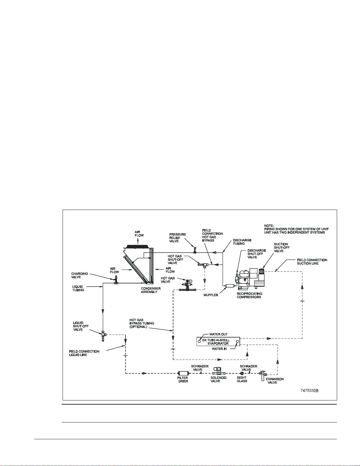
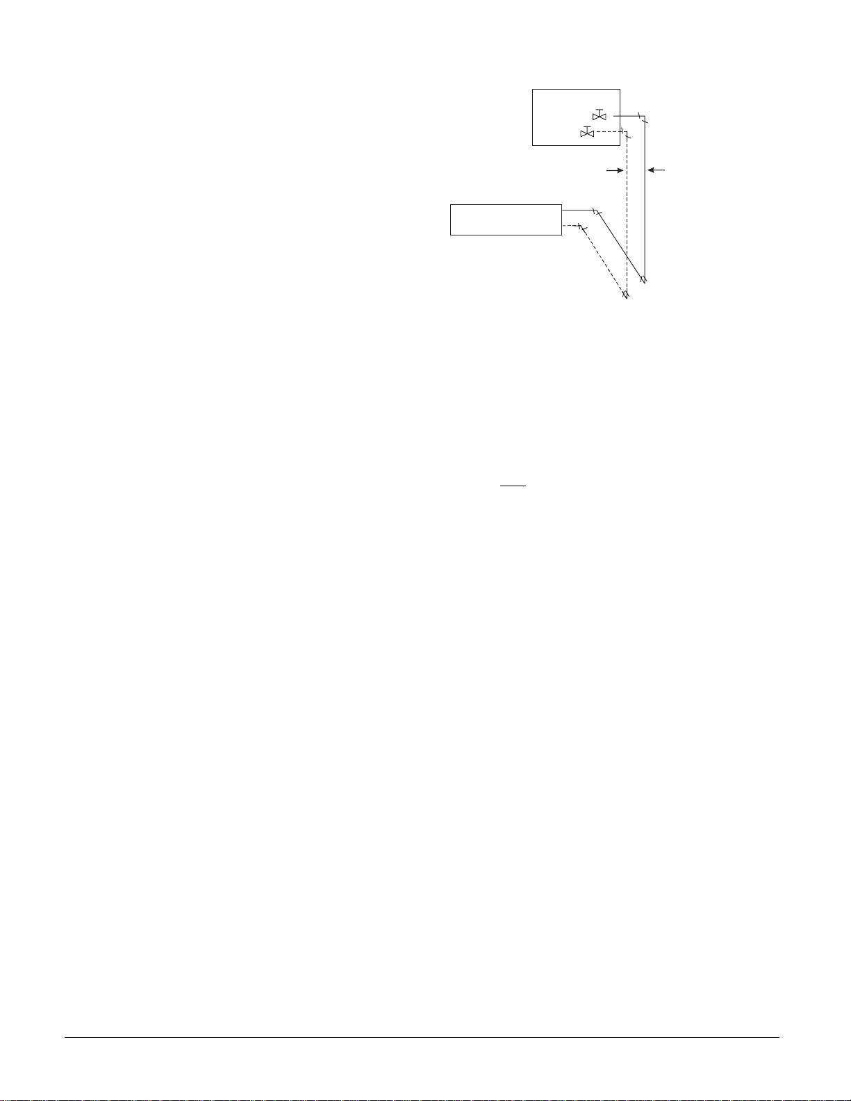
On Model AGR AM units the evaporator is shipped separate for field mounting and piping to the outdoor unit.
The refrigerant specialties shown in Figure 1 (dotted lines) must be purchased from McQuay with the unit and
installed by the installing contractor.
NOTE:
The remote evaporator option is available on R-22 application only and is outside ARI certification.
Figure 1, AGR ---AM, Remote E vaporator Piping (One of two circuits shown)
NOTE:
protect against evaporator freeze-up under low water flow conditions.
Product Manual AGR-3 AGR 070A through 100A
A water flow switch or both water flow switch and water pump starter interlock, must be field installed to
5
Page 6
Electrical Control Center
Operating and equipment protection controls and motor starting components are separately housed in a
centrally located, weatherproof control panel with hinged and key locked doors. In addition to one of
the three types of control described in the next sections, the following components are housed in the
panel:
Power terminal block
•
Control, input, and output terminal block
•
120V control circuit transformer
•
Optional disconnect switch with through-the-door operating handle
•
Compressor contactors (circuit breakers are available as an option) (part winding on 208/230V,
•
across-the-line on 380/460/575V) compressor motor inherent thermal and overload protection is
standard.
Optional phase voltage monitor with under/over/phase reversal protection
•
Fan contactors with separate fuse blocks
•
The standard FanTrol system controls fan staging for control of refrigerant discharge pressure.
•
The FanTrol system cycles condenser fans based on discharge pressure and outdoor temperature
and is suited for operation to 40°F (4.4°C).
The optional SpeedTrol control uses both fan cycling and fan speed control on the lead fan per
•
circuit and allows operation to 0°F (-18°C) outdoor temperature.
Mechanical high pressure cutout
•
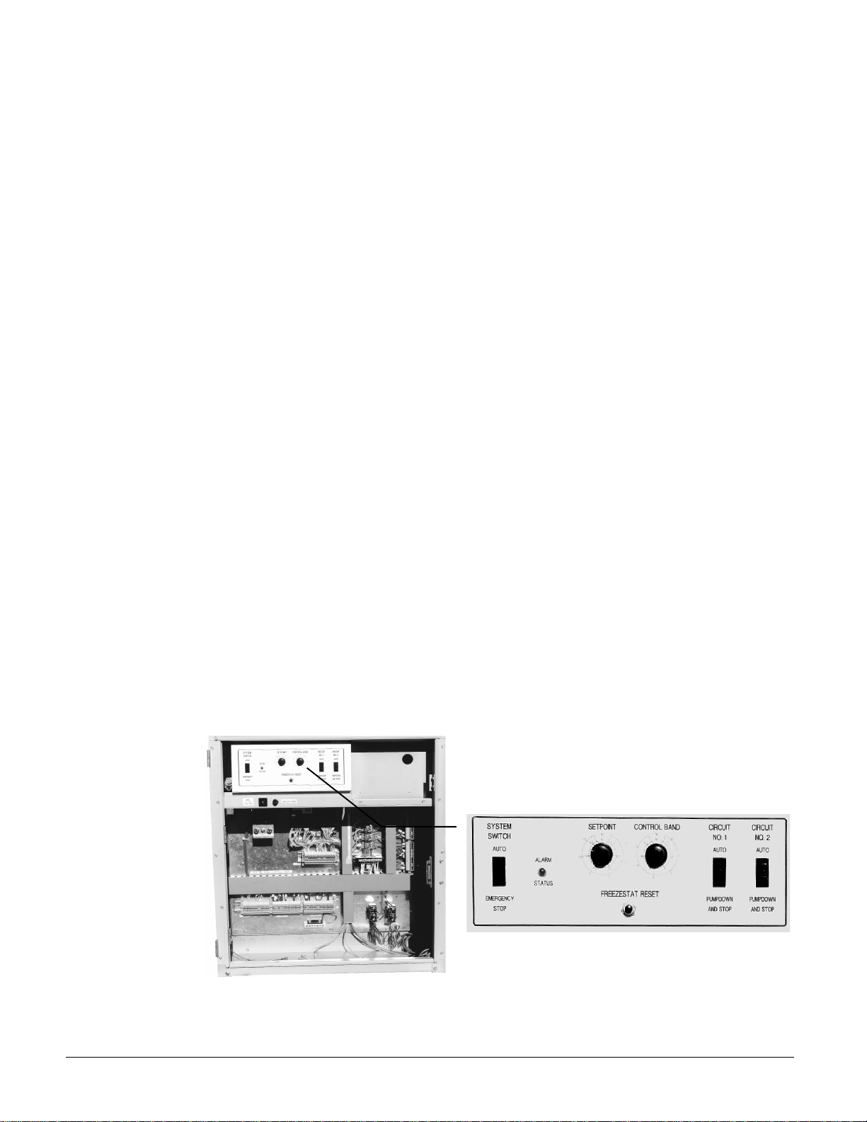
Global UNT Controller (Standard on R-22)
Microprocessor based control that accomplishes unit capacity control by 6-stage cross-circuit
compressor cycling and unloading based on leaving chilled water temperature. Setpoint and control
band are easily field adjusted. Anti-cycling and stage delay timers are included. Equipment protection
controls include low refrigerant pressure, low evaporator flow (field installed flow switch), low oil
pressure, and sensor failures. Outside air temperature sensor is standard. Reset options are; outside air,
return water, remote reset, demand limit, zone temperature reset. The optional Zone Terminal control is
required to adjust the reset setpoints. The UNT control is used only with R-22.
Thirty feet of sensor cable is included, rolled up in the control panel, on remote evaporator models.
Figure 2, Standard Global UNT Controller
6
AGR 070A through 100A Product Manual AGR-3
Page 7
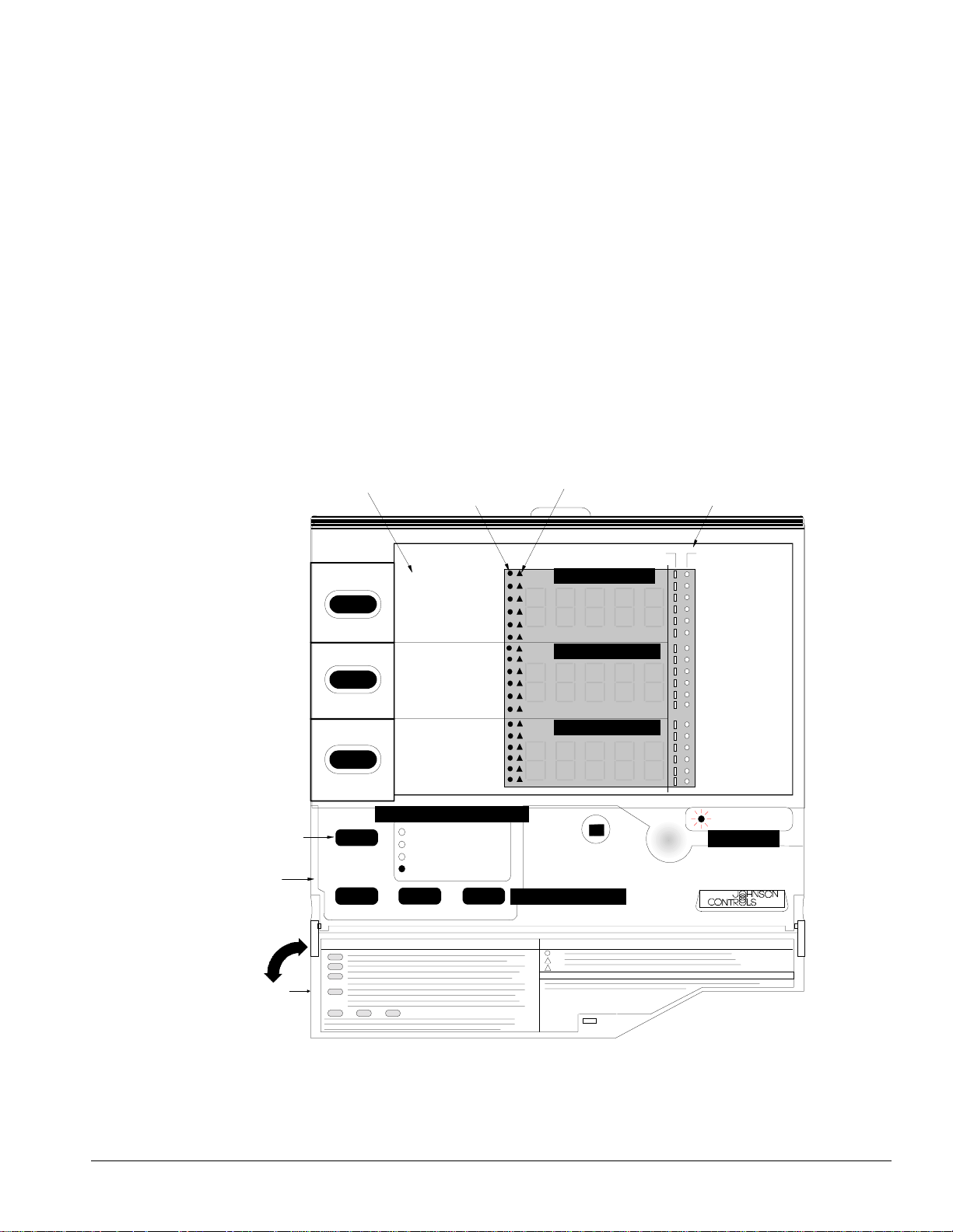
Global UNT with Zone Terminal (optional)
Can be mounted in the chiller control panel or remotely located providing monitoring and adjusting of
certain functions.
Monitoring
•
Monitor up to three setting or sensed values
•
Monitor 18 different on/off inputs
•
Monitor alarm status via a flashing alarm light and flashing symbol
•
Adjusting allows adjustment of any flashing set points, three at a time, typically set up so that the
•
relationship between values can be viewed simultaneously. For example,
Display 1 = Lvg Water temp
•
Display 2 = Lvg Water SP
•
Display 3 = % Unit Load
•
Figure 3, Zone Terminal Configuration
Display Item List
Display Indicator Dot
Warning Signal
On/Off St at us
Display
Button 1
Mode
Selector
Button
Mode
Selector
Panel
Door
2
3
McQuay AGZ/AGR Global Chiller
Lvg Water Temp
Evap Pres #1
Evap Pres #2
OA/AI3 Input
OA/AI3 HiLimSP
OA/AI3 ResetSP
Lvg Water SP
LvgWtr RBnd SP
Contrl Band SP
Actual Lvg SP
Unoccpd Lvg SP
OA Lockout SP
% Unit Load
Lvg Low Lim SP
SoftSta Capcty
SoftStart Time
Cir #1 Starts
Cir #2 Starts
Operating Mode Indicator
MONITOR
ADJUST
TIME SCHEDULE
PASSWORD
ENTER
INSERT 10
Display Area 11
Display Area 21
Display Area 31
Up/Down Arrow Keys
ON OFF
Occupied
Flow Failure
OA Lockout
Cir#2Lead=On
Pmp/Stp #1=0
Pmp/Stp #2=0
Solenoid #1
Solenoid #2
Frzstat#1Alm
Frzstat#2Alm
MinLowPres#1
MinLowPres#2
Compressor 1
Compressor 2
Stage 3
Stage 4
Stage 5 Opt.
Stage 6 Opt.
ALARM
Alarm Light
AGZ-AGR
Product Manual AGR-3 AGR 070A through 100A
7
Page 8
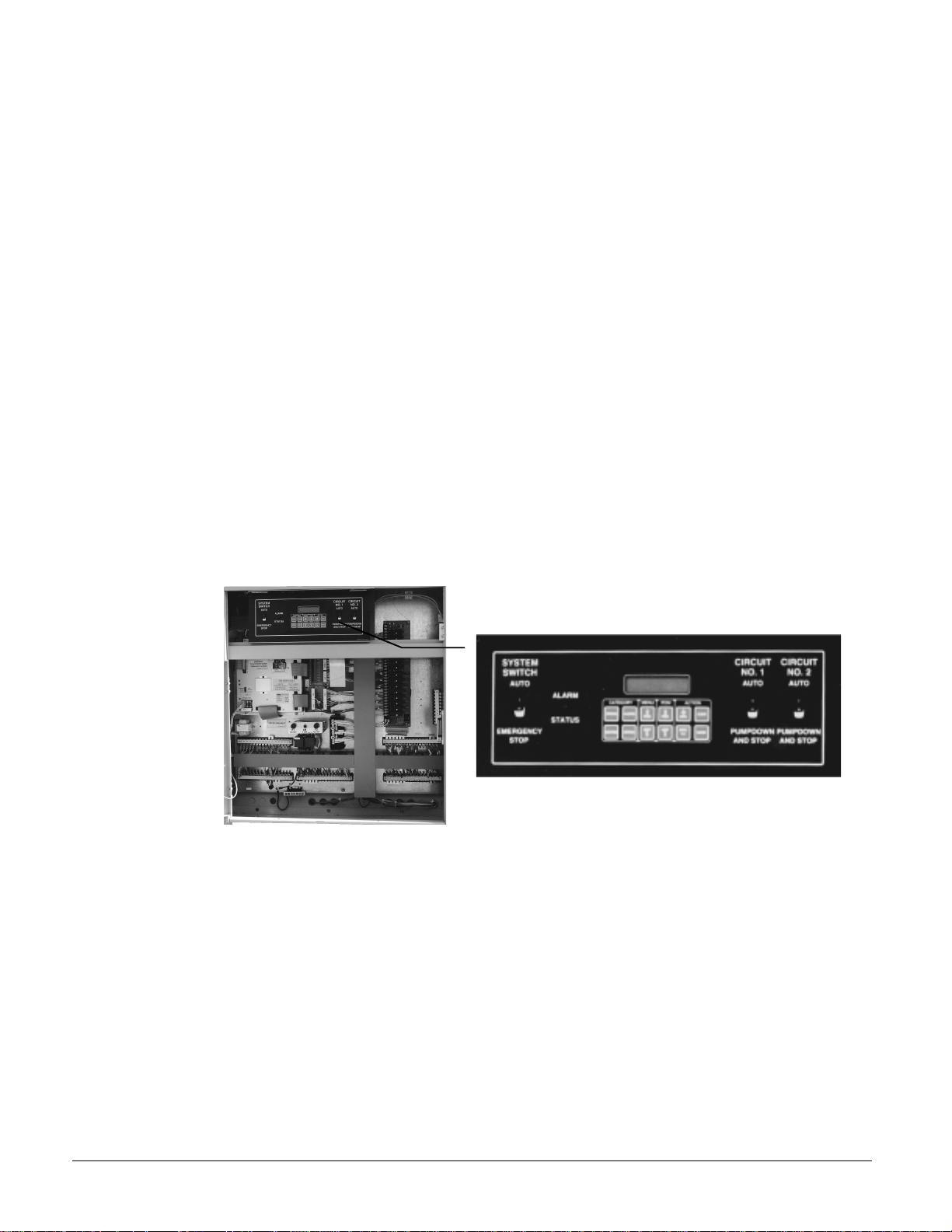
MicroTech Control (optional on R-22, standard on R-134a)
Exclusive microprocessor control is common throughout McQuay equipment. The interface is a 12 key
keypad and 2-line, 40 character backlit liquid crystal display. The MicroTech continuously performs
self-diagnostic checks on all system temperatures, pressures, and equipment protection controls, and
will automatically shut down a circuit or the entire unit at fault conditions. The cause, time, and date of
the occurrence is recorded and can be displayed. The seven previous incidents are kept in memory for
service reference.
If a fault occurs, the controller takes preventive measures in an effort to keep the unit operating; staging
down capacity, activating a pre-alarm signal, and automatically switching to the alarm menu on the
display. Pre-alarms are self-clearing when the fault condition is no longer present.
Critical shutdown alarms such as high condenser pressure (with mechanical back up), freeze protection,
oil pressure (with mechanical back up), and low evaporator pressure are manual reset and must be
cleared at the keypad to resume operation.
Choose the MicroTech control and Open Protocol options to interface with virtually any building
management system and perform remot e monitor ing and co ntrol b y hard wiring o r mod em. A no minal
site license fee is required for BAS interface.
A single chiller can connect directly to the BAS. Two or more units will require an Open Protocol
Panel (OPM) for connection.
One hundred feet of sensor cable is included, rolled up in the control panel, on remote evaporator
models.
NOTE:
Figure 4, Optional MicroTech Control Panel
The MicroTech control is required on R-134a applications.
8
AGR 070A through 100A Product Manual AGR-3
Page 9
Selection Procedure
Packaged Chiller, Model AS, R-22
Selection with Inch-Pound (I-P) units
Table 9 covers the range of leaving evaporator water temperatures and outside ambient temperatures
included under ARI 550/590. The tables are based on a 10°F temperature drop through the evapor ator.
Adjustment factors for applications having other than a 10°F drop can be found in Table 3. The
minimum leaving chilled water temperature setpoint without glycol is 42°F. For glycol selections, see
Table 1 for ethylene or Table 2 for propylene glycol adjustment factors. Ratings are based on a 0.0001
fouling factor in the evaporator at sea level operation. For other fouling factors, different delta-Ts, or
altitude correction factors, see Table 3. For applications outside the catalog ratings contact your local
McQuay sales representative.
Selection example
Given: 67 tons minimum 95°F ambient temperature
160 gpm, 55°F to 44°F chilled water 0.0001 fouling factor
1. From Performance Table 9, an AGR 070AS at the given conditions will produce 67.5 tons with a
compressor kW input of 77.1 and a unit EER of 9.6.
2. If any elements are unkno wn, use the following equation (water only) to calculate them:
tons−×
=GPM
24
Tdelta
3 Determine the evaporator pressure drop. Using Figure 9, enter at 160 and follow up to the AGR
070AS line intersect. Read horizontally to obtain an evaporator pressure drop of 16.0 feet of water.
Selection example using ethylene glycol
Given:
64 tons minimum
95°F ambient temperature
54°F to 44°F chilled fluid
0.0001 fouling factor
Protect from freezing down to 0°F
1. From Table 1, select an ethylene glycol concentration of 40% to protect against freezing at 0°F.
2. At 40% ethylene glycol, the adjustment factors are: Capacity =0.961, kW = 0.976,
flow = 1.121, pressure drop = 1.263
3. Select the AGR 070AS and correct with 40% ethylene glycol factors.
4. Correct capacity = 0.961 x 67.5 tons = 64.9 tons
5. Correct compressor kW = 0.976 x 77.1 = 75.2 kW
6. Calculate chilled water flow:
249.64
tons°×
= capacity) corrected(at flowWater
10
F
Glycol flow (at 40% solution) = 1.121 X 155.8 = 174.7 GPM
155.8 =
GPM
Determine the evaporator pressure drop. Using Figure 9, enter at 155.7 (flow rate for water) and follow
up to the AGR 070AS line intersect. Read horizontally to obtain an evaporator pressure drop of 15.5
feet. The pressure drop for 40% glycol solution = 1.263 X 15.5 feet = 19.6 feet of water.
Product Manual AGR-3 AGR 070A through 100A
9
Page 10

Selection Procedure 60 Hertz, SI Units
Table 10, covers a range of leaving evaporator water temperatures and outside ambient temperatures.
The tables are b ased on a 5°C temper ature dro p through the evapo rator. The minimum leaving chilled
water temperature setpoint without glycol is 5.6°C. For brine selections, see Table 1 for ethylene or
Table 2 for propylene glycol adjustment factors. Ratings are based on a 0.0176 fouling factor in the
evaporator at sea level operation. For other fouling factors, different Delta-Ts, or altitude correction
factors, see Table 3. For applications outside the catalog ratings contact your local McQuay sales
representative.
Selection Example
Given:
235 kW cooling capacity required
35°C ambient air temperature
11 L/s, 12°C - 7°C chilled water temperature
0.0176 evaporator fouling factor
1. From Table 10, an AGR 070AS at the given conditions will produce 240.0 kW with a compressor
kW input of 77.5 and a COP of 2.84.
2. Determine the evaporator pressure drop. Using Figure 9, enter at 11 L/s and follow to the AGR
070AS line intersect. Read horizontally to obtain an evaporator pressure drop of 55 kPa of water.
Selection example using ethylene glycol
Given:
225 kW cooling capacity required
35°C ambient air temperature
11 L/s, 12°C - 7°C chilled water temperature
0.0176 evaporator fouling factor
Protect against freezing down to -18°C
1. From Table 1, select an ethylene glycol concentration of 40% to protect against freezing
at -18°C
2. At 40% ethylene glycol, the adjustment factors are: Capacity = 0.961, kW = 0.976,
GPM = 1.121, pressure drop = 1.263
3. Select the AGR 070AS and correct with 40% ethylene glycol factors.
4. Correct capacity = 0.961 x 240.0 kW = 230.6 kW
5. Correct compressor kW = 0.976 x 77.5 kW = 75.6 kW
6. Calculate flow:
Glycol flow (at 40% solution) = 1.121 X 11.0 L/s = 12.3 L/s
7. Determine the evaporator pressure drop. Using Figure 9, enter at 11.0 L/s (flow rate for water) and
follow to the AGR 070AS line intersect. Read horizontally to obtain an evaporator pressure drop
of 55 kPa of water.
The pressure drop for 40% solution = 1.263 X 55 kPa = 69.5 kPa
10
AGR 070A through 100A Product Manual AGR-3
Page 11

Packaged Chiller, Model AS, R-134a
NOTE: R-134a performance is not ARI Certified
AGR performance with R-134a refrigerant is calculated from the R-22 ratings as follows:
1) Calculate the unit R-134a capacity;
2) Calculate the unit R-134a power input;
a) Calculate the unit R-22 power (kW shown in tables is compressor only);
22
b) Calculate the unit fan and control power (unaffected by refrigerant);
c) Calculate the R-134a compressor power;
d) Calculate the unit R-134a kW;
3) Calculate R-134a EER:
kWUnitR
−
=
134
multiply the R-22 capacity by 0.68.
12022
xTonsR
EERUnit
2222/
−=
multiply the R-22 compressor kW by 0.615
fan & contro l power from b)+R-134a compressor power c)
EERaR
134
=
134
MBHcapacityaR
kWUnitaR
TablefromkWCompressorRkWUnitRkWControlFan
Remote Evaporator, Model AM
Selection with Inch-Pound (I-P) units
Since the AGR-AM units always include a specific remote shell-and-tube evaporator, the ratings are based on leaving chilled water temperature and ambient air temperature from the Rating Tables corrected for line loss as follows.
Table 9 (Inch-Pound units) and Table 10 (SI units) cover the normal range of leaving evaporator water
temperatures and outside ambient air temperatures. The tables are based on a 10°F (5°C) temperature
drop thro ugh the evapora tor. Adjustment factors for applicati ons having other tha n a 10°F (5°C) drop
can be found in Table 3. The minimum leaving chilled water temperature setpoint without glycol is
42°F (5.6°C). For brine selections, see Table 1 for ethylene Table 2 for propylene glycol adjustment
factors. Ratings are based on a 0.0001 (0.0176) fouling factor in the evaporator at sea level operation.
For other fouling factors, derates for different delta-Ts, or altitude correction factors, see Table 3 . For
applications outside the catalog ratings contact your local McQuay sales representative.
The length and configuration of the interconnecting refrigerant piping will affect the system capacity.
Derates base d on e q uival ent lengt h o f pip e ar e gi ven i n Table 8. Re fer to App li ca tio n Da ta , Re fri ger ant
Piping section for guidelines.
The steps for selecting an AGR-AM are as follows:
1. Add 3% to the required cooling capacity (to approximate correction factors) and make a
preliminary unit selection from performance Table 9 or Table 10.
2. Divide the required capacity by the appropriate capacity correction factors: glycols from Table 1 or
Table 2; altitude, chilled water Delta T, or fouling factor Table 3; and refrigerant piping derate from
Table 8 as explained in step 3 below.
3. Determine the suction line size by summing the equivalent feet (from Table 4) of all the fittings
(use a sketch of the piping layout) and
of tubing. This will then equal the
unit suction connection size from Table 6 as the first try). Knowing the equivalent feet and the unit
size, check the line selection in Table 6 or Table 7 and correct if required.
4. If the unit rated capacity in the tables is less than the corrected required cap acity, redo the selection
with the next larger unit. In most cases the line size will be the unit connection size. If the
selection is satisfactory, correct the power (if applicable) and determine water pressure drop.
Product Manual AGR-3 AGR 070A through 100A
adding the sum of these fitting losses
total equivalent feet
to the actual linear feet
. (To use the equivalent feet, start with the
11
Page 12
Selection example
A
p
Given:
Figure 5, Sample Piping Layout
GR-AM
10 ft.
64 tons required capacity
95°F ambient temperature
Cool 154 gpm from 54°F to 44°F
0.0001 evaporator fouling factor
2,000 foot altitude
Remote Eva
orator
10 ft.
Liquid
Line
20 ft.
Suction
Line
30 ft.
Add 3% to the required capacity for approximate derate: 64 x 1.03 = 66 tons. From Performance Table
9, an AGR-070AM at the given conditions will produce 67.5 tons with a compressor kW input of 77.1
and a unit EER of 9.6.
1. Determine derate factors :
Altitude correction from Table 3: 0.986 Capacity, 1.009 Power
2. Piping cor rection:
Assume 2 1/8" suction line based on connection size in Table 6
(3) 90° Standard ells (Table 4) 3 x 5 ft =15 ft
Plus actual linear feet 70 ft
Total Equivalent Feet 85 ft
Check Table 7 for size and find that 2 1/8” is acceptable size for oil carry. If the selected riser size
is too large, double risers would be required. See Refrigerant Piping section for important
information, including double riser layouts.
The capacity correction factor from Table 8 is 0.984.
3. The corrected capacity of the AGR is: 67.5 tons x 0.986{altitude} x 0.984{piping} = 65.5 tons
This satisfies the 64 ton requirement.
4. Correct the compressor power required: 77.1 kW x 1.009{altitude} = 77.8 kW.
5. Calculate the unit power input from corrected EER:
W = BTU / EER W =65.5 tons x 12,000 / (9.6 EER / 1.009) = 81.1 kW
6. Determine the evaporator pressure drop. Enter the pressure drop curves (Figure 9) at 154 gpm and
read up to AGR 070AM, read over to pressure drop of 15 ft.
Selection example using ethylene glycol
Given: 64 tons required capacity
95°F ambient temperature
54°F to 44°F chilled fluid
0.0001 fouling factor
Protect from freezing down to 0°F
1. From Table 1, select an ethylene glycol concentration of 40% to protect against freezing at 0°F.
2. At 40% ethylene glycol, the adjustment factors are: Capacity =0.961, kW = 0.976,
Flow = 1.121, pressure drop = 1.263
3. Select the AGR 070AM and correct with 40% ethylene glycol factors and piping correction factor.
4. Correct capacity = 0.961 X 67.5 tons = 64.6 tons
5. Correct compressor kW = 0.976 X 77.1 = 75.2 kW
12
AGR 070A through 100A Product Manual AGR-3
Page 13
6. Calculate chilled water flow:
Water flow (at corrected capacity) = = 155.3 GPM
Glycol flow (at 40% solution) = 1.121 X 155.3 GPM = 174.1 GPM
Determine the evaporator pressure drop. Using Figure 9, enter at 155.3 GPM and follow up to the
AGR 070AM line intersect. Read horizontally to obtain an evaporator pressure drop of 15 feet. The
pressure drop for 40% solution = 1.263 X 15 feet = 19 feet.
Selection Procedure 60 Hz Metric Units
The selection procedure for Metric units is exactly the same as English except that Metric tables and
metric units are used.
Application Adjustment Factors
Ethylene and Propylene Glycol Factors
AGR units can operate with a leaving chilled fluid temperature range of 20°F (-6.7°C) to 60°F
(15.6°C). A glycol solution is required when leaving chilled fluid temperature is below 42°F (5.6°C).
The use of glycol will reduce the performance of the unit depending on concentration.
64.7 24
tonsF×
10
°
Altitude Correction Factors
Performance tables are based at sea level. Elevations other than sea level affect the performance of the
unit. The decreased air density will reduce condenser capacity and reduce the unit's performance. For
performance at elevations other than sea level refer to Table 3. Maximum allowable altitude is 6,000
feet (1830 meters).
Evaporator Temperature Drop Factors
Performance tab les are ba sed on a 10 °F (5.5°C) temperature drop through the evapora tor. Adjustment
factors for applications with temperature ranges from 6°F to 16°F (3.3°C to 8.9°C) are in Table 3.
Temperature drops outside this 6 to 16 degrees F (3.3 to 8.9 degrees C) range may affect the control
system's capability to maintain acceptable control and are not recommended.
The maximum water temperatur e that ca n b e c ir cul at ed thr o ugh the eva po r a to r i n a non-o p e ra ti ng mod e
is 100°F (37.8°C). Maximum entering temperature during operation is 90°F (32.2°C).
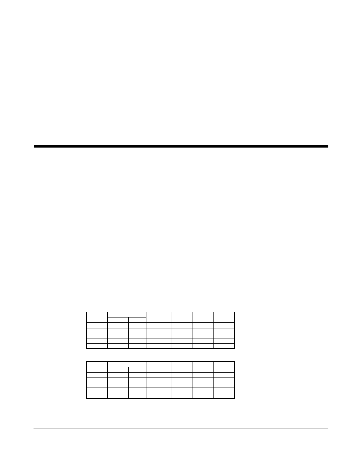
Table 1, Ethylene Glycol
%
E.G.
10 23.0 -5 0.991 0.996 1.013 1.070
20 14.0 -10 0.982 0.992 1.040 1.129
30 1.4 -17 0.972 0.986 1.074 1.181
40 -13.0 -25 0.961 0.976 1.121 1.263
50 -34.6 -37 0.946 0.966 1.178 1.308
Table 2, Propylene glycol
%
P.G.
10 26 -3 0.987 0.992 1.010 1.068
20 19 -7 0.975 0.985 1.028 1.147
30 9 -13 0.962 0.978 1.050 1.248
40 -5 -21 0.946 0.971 1.078 1.366
50 -27 -33 0.929 0.965 1.116 1.481
NOTE: Ethylene and propylene glycol ratings are outside the scope of
Freeze Point
°F °C
Freeze Point
°F °C
Standard 550/590-98 certification program
Capacity Power Flow PD
Capacity Power Flow PD
Product Manual AGR-3 AGR 070A through 100A
13
Page 14
Fouling factor
Performance tables are based on water with a fouling factor of
22
per ARI 550/590-98. As fouling increases,
/0176.0,,/0001.0
°×°
kWCmorBTUFxhrxft
performance decreases. For performance at other than 0.0001 (0.0176) fouling factor see Table 3.
Foreign matter in the chilled water system will adversely affect the heat transfer capability of the
evaporator, and could increase the pressure drop and reduce the water flow. To ensure optimum unit
operation, maintain proper water treatment.
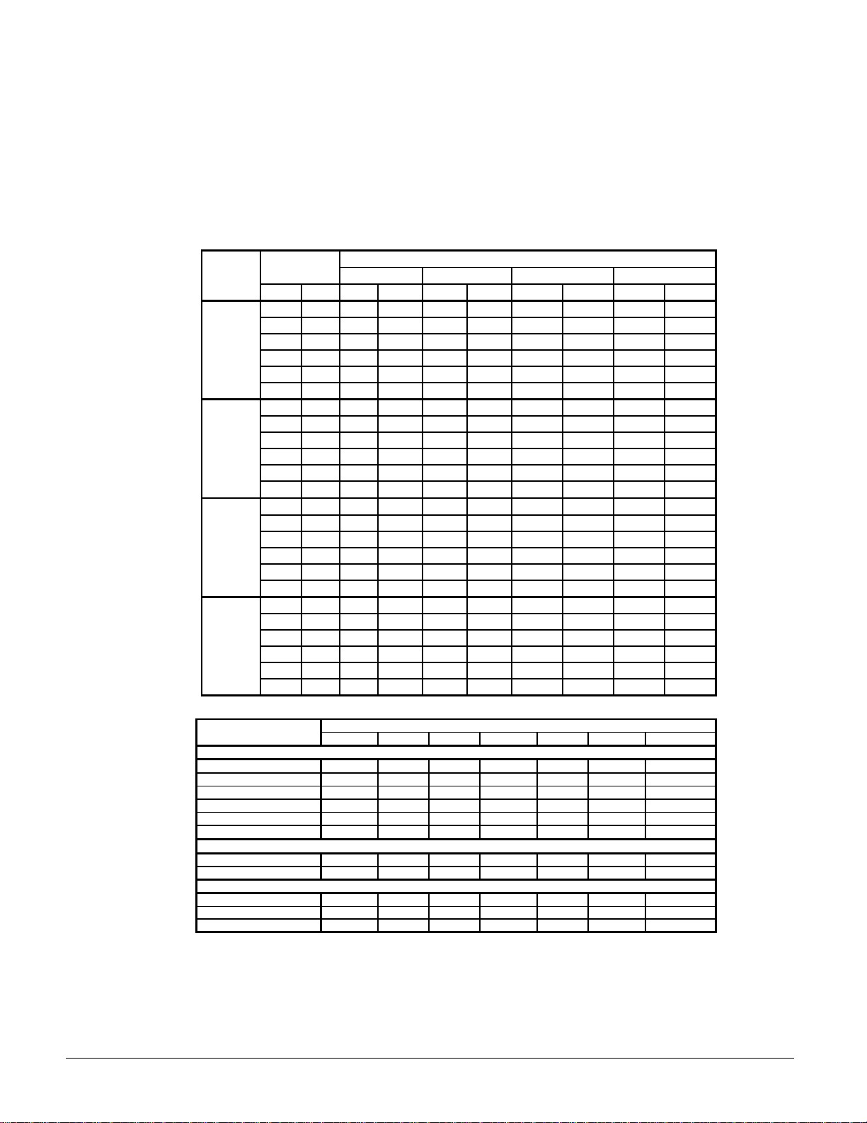
Table 3, Capacity and Power Derates
Chilled Water
ALTITUDE
SEA 10 5.6 1.000 1.000 0.993 0.998 0.970 0.991 0.927 0.977
LEVEL 12 6.7 1.005 1.002 0.998 1.000 0.975 0.993 0.932 0.979
2000 feet 10 5.6 0.986 1.009 0.979 1.007 0.956 1.000 0.914 0.986
(610 m) 12 6.7 0.992 1.011 0.985 1.009 0.962 1.002 0.919 0.988
4000 feet 10 5.6 0.973 1.021 0.966 1.019 0.944 1.012 0.902 0.998
(1220 m) 12 6.7 0.978 1.025 0.971 1.023 0.949 1.016 0.906 1.002
6000 feet 10 5.6 0.959 1.031 0.952 1.029 0.930 1.022 0.889 1.008
(1830 m) 12 6.7 0.963 1.034 0.956 1.032 0.934 1.024 0.893 1.011
Delta-T
°F °C Cap. Power Cap. Power Cap. Power Cap. Power
6 3.3 0.992 0.995 0.985 0.993 0.962 0.986 0.919 0.972
8 4.4 0.995 0.997 0.988 0.995 0.965 0.988 0.922 0.974
14 6.8 1.010 1.005 1.003 1.003 0.980 0.996 0.936 0.982
16 8.9 1.014 1.007 1.007 1.005 0.984 0.998 0.940 0.984
6 3.3 0.978 1.005 0.971 1.003 0.949 0.996 0.906 0.982
8 4.4 0.982 1.007 0.975 1.005 0.953 0.998 0.910 0.984
14 6.8 0.997 1.014 0.990 1.012 0.967 1.005 0.924 0.991
16 8.9 1.000 1.016 0.993 1.014 0.970 1.007 0.927 0.993
6 3.3 0.966 1.016 0.959 1.014 0.937 1.007 0.895 0.993
8 4.4 0.969 1.018 0.962 1.016 0.940 1.009 0.898 0.995
14 6.8 0.982 1.027 0.975 1.025 0.953 1.018 0.910 1.004
16 8.9 0.986 1.028 0.979 1.026 0.956 1.019 0.914 1.005
6 3.3 0.953 1.025 0.946 1.023 0.924 1.016 0.883 1.002
8 4.4 0.955 1.028 0.948 1.026 0.926 1.019 0.885 1.005
14 6.8 0.968 1.036 0.961 1.034 0.939 1.026 0.897 1.013
16 8.9 0.972 1.037 0.965 1.035 0.943 1.027 0.901 1.014
0.0001 (0.0176) 0.00025 (0.044) 0.00075 (0.132) 0.00175 (0.308)
Table 4, Equivalent Feet for Fittings
Fitting Type
Elbows
90° Standard
90° Long Radius
90° Street
45° Standard
45° Street
180° Bend
Tees
Full Size 1.4 1.7 2.3 2.6 3.3 4.1 5.0
Reducing 2.0 2.6 3.3 4.0 5.0 6.0 7.5
Valves
Globe Valve, Open 22 29 38 43 55 69 84
Gate Valve, Open 0.9 1.0 1.5 1.8 2.3 2.8 3.2
Angle Valve, Open 9.0 12 15 18 24 29 35
7/8 1 1/8 1 3/8 1 5/8 2 1/8 2 5/8 3 1/8
2.0 2.6 3.3 4.0 5.0 6.0 7.5
1.4 1.7 2.3 2.6 3.3 4.1 5.0
3.2 4.1 5.6 6.3 8.2 10 12
0.9 1.3 1.7 2.1 2.6 3.2 4.0
1.5 2.1 3.0 3.4 4.5 5.2 6.4
3.2 4.1 5.6 6.3 8.2 10 12
Fouling Factor
Line Size inch, OD Copper
14
AGR 070A through 100A Product Manual AGR-3
Page 15
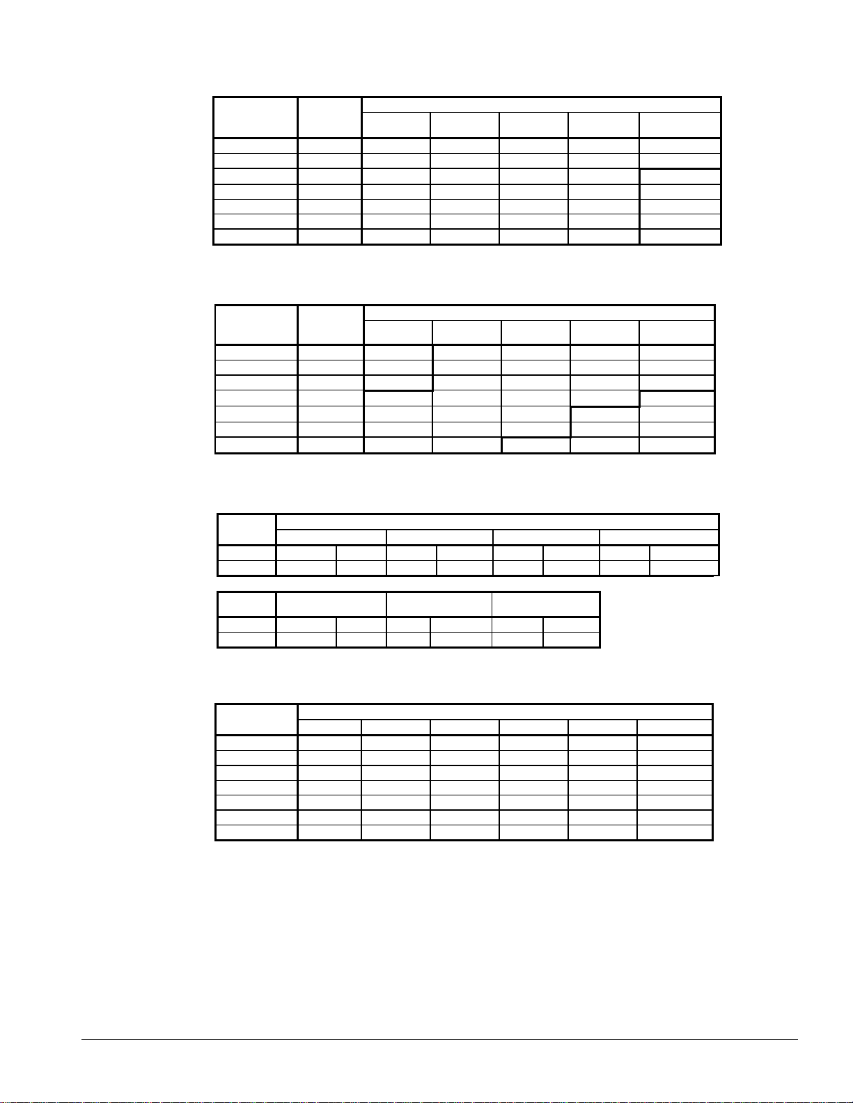
Table 5, Recommended Liquid Line Sizes Per Refrigerant Circuit
AGR-AM
Unit Model
070AM
075AM
080AM
085AM
090AM
095AM
100AM
Liquid
Connection
Size at Unit
1 1/8" 1 1/8 " 1 1/8 " 1 1/8 " 1 1/8 " 1 1/8 "
1 1/8" 1 1/8 " 1 1/8 " 1 1/8 " 1 1/8 " 1 1/8 "
1 1/8" 1 1/8 " 1 1/8 " 1 1/8 " 1 1/8 "
1 1/8" 1 1/8 " 1 1/8 " 1 1/8 " 1 1/8 "
1 1/8" 1 1/8 " 1 1/8 " 1 1/8 " 1 1/8 "
1 1/8" 1 1/8 " 1 1/8 " 1 1/8 " 1 1/8 "
1 1/8" 1 1/8 " 1 1/8 " 1 1/8 " 1 1/8 "
Up To 50
Equiv. Feet
Recommended Liquid Line Size Per Circuit
Up To 75
Equiv. Feet
Up To 100
Equiv. Feet
Up To 125
Equiv. Feet
Table 6. Recommended Horizontal and Downflow Suction Line Size
AGR-AM
Unit Model
070AM 2 1/8" 2 1/8"
075AM 2 1/8" 2 1/8"
080AM 2 1/8", 2 5/8" 2 1/8", 2 5/8"
085AM 2 5/8"
090AM 2 5/8"
095AM 2 5/8"
100AM 2 5/8"
Suction
Connection
Size at Unit
Up To 50
Equiv. Feet
2 5/8" 2 5/8" 2 5/8" 2 5/8"
2 5/8" 2 5/8" 2 5/8"
2 5/8" 2 5/8" 2 5/8"
2 5/8" 2 5/8"
Recommended Suction Line Size
Up To 75
Equiv. Feet
2 5/8" 2 5/8" 2 5/8" 2 5/8"
2 5/8" 2 5/8" 2 5/8" 2 5/8"
2 5/8" 2 5/8" 2 5/8" 2 5/8"
Up To 100
Equiv. Feet
3 1/8" 3 1/8" 3 1/8"
Up To 125
Equiv. Feet
3 1/8" 3 1/8"
3 1/8" 3 1/8"
Up To 150
Equiv. Feet
1 3/8"
1 3/8"
1 3/8"
1 3/8"
1 3/8"
Up To 150
Equiv. Feet
3 1/8"
Table 7, Minimum Suction Riser Size
AGR
Model
System1 212121 2
Line Size 2 1/8 2 1/8 2 1/8 2 1/8 2 1/8 2 5/8 2 5/8 2 5/8
AGR
Model
System 1 2 1 2 1 2
Line Size 2 5/8 2 5/8 2 5/8 2 5/8 2 5/8 2 5/8
070AM 075AM 080AM 085AM
090AM 095AM 100AM
Minimum Suction Riser for Oil Carry by Unit System
Table 8, Refrigerant Piping Derates
AGR-AM
Unit Model
070AM 1.0 0.969
075AM 1.0 0.969
080AM 1.0 0.961
085AM 1.0
090AM 1.0
095AM 1.0
100AM 1.0
At Unit 50 Equiv. ft. 75 Equiv. ft. 100 Equiv. ft. 125 Equiv. ft. 150 Equiv. ft.
Capacity Loss Due to Refrigerant Piping
0.984 0.978 0.973 0.967
0.984 0.978 0.973 0.967
0.978 0.971 0.963 0.957
0.982 0.974 0.966 0.957
0.979 0.968 0.957
0.979 0.968 0.957
0.976 0.964
0.980 0.975 0.971
0.978 0.974
0.978 0.974
0.978
Product Manual AGR-3 AGR 070A through 100A
15
Page 16
Performance Data
0
64.8
69
63
9.3
59.3
80.28.3
55.5
86
075.9
66
6
67.5
9.6
63.5
83.0
8.6
59.5
88.97.546.078.6
67.5
8
67.8
078.49.9
65.8
84.3
8.8
61.6
90
6
073.0
65
9
69.3
6
65.5
9
9.3
61.6
80.3
8.3
5
85.6
078.0
67.6
3
9.6
65.9
83.18.6
61.8
88.97.546.0
80.768
676
579.49.8
68.3
84.5
8.8
64.0
90.6
0
8
9
0
80
6
8
83.3
9.3
68.5
89.48.3
6
95.3
0
86
3
8
9
86.19.673.3
92.6
8.5
68.6
99.07.546.0
89
85.184.8
80.5
88.3
9.875.9
9
0
88.379.3
0
83.787.310
90.9
9
5
97.5
8.3
69
3
0
94.3
8
5
89.5
90
93.9
9
9
8.6
646.0
97.5
83
8
92.5
92.5
87.6
96.3
9.9
82.5102.6
8.8
0
90.3
80
85.788.310.8
8
91.9
9.576.298.5
8
0
96.5
83.0
6
9
86.794.9
9.8
81.5102.0
8
0
99.8
84.3
9
9
93.5
5
89.6
9
0
8
8
0
97.9
89.6
9
92.9
98.610.6
87.9102.6
9.3
82.6110.18.3
6
92.8
99.3101.8
0
94.0106.19.6
88
0
8.6
82.8
546.0108.29
9
8
9.8
91.5115.9
8.785.9
99
6
96
9
9.3
90
6
96
5
8.6
90.6135
546.0118.3104.5
8
9.8100
8
94.0137.87.6
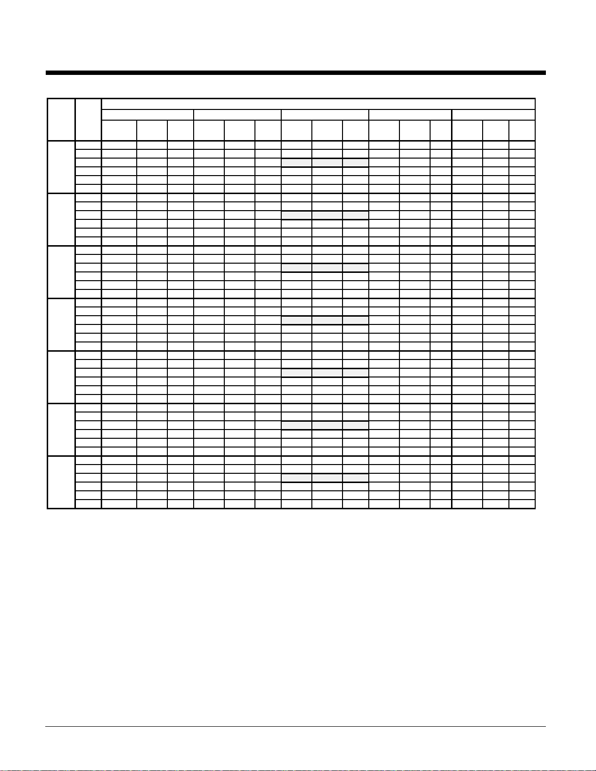
Table 9, AGR 070 – AGR 100, 60 Hz, R-22, I-P Units
See Selection Procedure section for derates for the "AM" remote evaporator units
AGR
LWT
SIZE
(°F)
Capac.
40.
42.0 73.5 65.5 12.4 69.4 70.5 10.9 65.3 75.4 9.5 61.4 81.5 8.5 57.5 87.5 7.4
44.
48.0 81.3 68.6 13.1 76.9 73.5 11.6 72.5 79.7 10.1 68.1 85.7 9.0 63.7 92.1 7.8
50.0 84.0 69.6 13.3 79.4 75.0 11.8 74.9 80.7 10.2 70.4 87.2 9.1 65.8 93.7 7.9
40.
42.0 75.5 66.8 12.1 71.7 73.1 10.8 67.8 76.0 9.5 63.7 81.7 8.4 59.5 87.3 7.4
44.
48.0 83.3 69.6 13.0 79.1 78.0 11.4 74.9 81.8 10.0 70.6 85.9 8.9 66.3 92.2 8.2
50.0 85.9 70.7 13.2 81.6 79.1 11.7 77.3 84.0 10.2 72.9 87.4 9.1 68.6 93.9 8.0
40.
42.0 83.9 74.5 12.2 79.7 81.4 10.8 75.4 84.7 9.5 70.7 91.0 8.4 66.1 97.2 7.3
44.
48.0 92.5 77.4 12.9 87.9 86.9 11.5 83.2 91.1 10.0 78.5 95.7 8.9 73.7 102.7 8.2
50.0 95.5 78.7 13.2 90.7 88.0 11.7 85.8 93.5 10.2 81.1 97.3 9.1 76.3 104.5 8.0
40.
42.0 91.3 81.2 12.3 86.6 88.7 10.9 81.9 92.4 9.5 76.9 99.3 8.5 71.9 106.0 7.4
44.
48.0 100.6 84.5 13.1 95.5 94.7 11.6 90.5 99.3 10.1 85.3 104.3 9.0 80.2 112.0 8.3
50.0 103.8 85.8 13.3 98.6 96.0 11.8 93.3 102.0 10.3 88.1 106.1 9.2 82.9 114.0 8.1
40.
42.0 93.4 82.1 12.4 88.7 89.7 11.0 83.9 93.4 9.6 78.7 100.3 8.6 73.6 107.1 7.5
44.
46.
48.0 103.0 85.4 13.2 97.8 95.8 11.7 92.6 100.4 10.2 87.3 105.4 9.1 82.0 113.2 8.4
50.0 106.3 86.7 13.5 100.9 97.0 11.9 95.5 103.1 10.4 90.2 107.2 9.3 84.9 115.2 8.2
40.
42.0 101.3 91.7 12.1 96.1 100.3 10.8 90.9 104.4 9.5 85.4 112.2 8.4 79.8 119.7 7.4
44.0104.
48.0 111.7 95.4 12.9 106.0 107.0 11.4 100.4 112.3 10.0 94.7 117.9 8.9 89.0 126.5 8.2
50.0 115.2 96.9 13.2 109.4 108.4 11.7 103.6 115.2 10.2 97.8 119.8 9.1 92.0 128.8 8.0
40.0107.1
42.0 110.8 101.8 12.2 105.2 111.2 10.7 99.5 115.8 9.5 93.3 124.4 8.4 87.3 132.9 7.3
44.0114.4 103.012.4 108.7 113.011.0102.8117.79.
48.0 122.1 105.9 12.9 116.0 118.8 11.4 109.8 124.5 10.0 103.5 130.8 8.9 97.2 140.4 8.2
Notes:
1. Boxed ratings certified in accordance with ARI Standard 550/590-98 for "AS" units only. Remote evaporator units (AM) are outside the ARI scope.
2. Ratings based on HCFC-22, evaporator fouling factor of 0.0001, 2.4 gpm/ton, and at sea level.
3. kWi input is for compressors only, EER is for the entire unit, including compressors, fan motors and control power.
4. For 208V units, multiply capacity and EER by 0.98
5. For units with SpeedTrol option, multiply capacity and EER by 0.98
6. Operation below 42°F requires glycol and performance adjustment.
7. Ratings can be interpolated but not extrapolated.
50.0 126.0 107.6 13.2 119.7 120.4 11.7 113.3 127.8 10.2 107.0 133.0 9.1 100.6 142.9 7.9
75°F 85°F 95°F 105°F 115°F
PWR
Tons
71.1
1.2 72.811.
kWi
.2 12.
.4 11.
.7 12.7 76.
.7 75.312.482.
.7 76.512.7
2.2 12.
.4 12.
.2 12.2
4.2 12.6102.7 104.511.2
.4 11.9101.7 109.510.
Capac.
EER
Tons
12.167.1
12.
12.4 74.1 74.2 11.070.1 77.
12.
12.791.
12.
11.
12.4
12.7 112.4 115.911.2 106.3120.
PWR
kWi
.4 10.7
71.7 71.511.1
77.
72.4 11.4 70.
71.910.
.1 11.2 72.
.1 10.
2.7 11.077.
.1 11.184.7
1.1 11.2
4.7
AMBIENT AIR TEMPERATURE
EER
11.2
.7 79.2
11.4
11.
11.
Capac.
Tons
PWR
kWi
.1 74.1
77.1
74.
72.
1.1
7.4 10.
7.2 108.
.1 113.
Capac.
EER
Tons
.4 74.
.7 79.7 100.
4.4 103.78.979.2 111.1 7.
.4 114.
.4 122.28.284.6130.37.2
.7 126.
.1 128.78.
PWR
kWi
4.18.7 71.2 100.87.7
Capac.
EER
.4 71.4 105.1 7.4
.7 76.4 109.1 7.7
PWR
Tons
7.7
4.1
.7 103.97.
74.6108.07.
77.4 110.07.7
77.4 117.4 7.2
122.07.
124.37.7
kWi
.1 7.2
.4 7.
.4 7.
EER
7.2
7.7
7.2
16
AGR 070A through 100A Product Manual AGR-3
Page 17
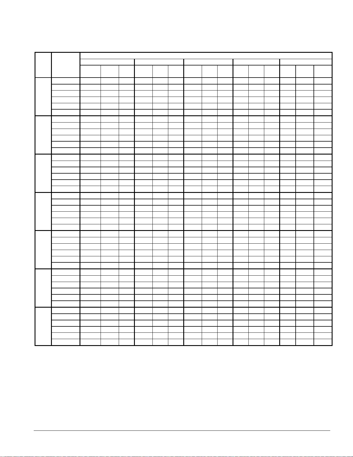
Table 10, AGR 070 – AGR 100, 60 Hz, R-22, SI Units
See Selection Procedure section for derates for the "AM" remote evaporator units
AMBIENT AIR TEMPERATURE
LWT
SIZE
070AS 7.0 (44.6°F) 265.4 67.6 3.62 247.2 72.4 3.24 240.0 77.5 2.84 227.2 82.8 2.56 214.3 88.1 2.28
070AM 8.0 (46.4°F) 271.6 68.7 3.68 245.1 73.2 3.30 247.9 78.7 2.92 234.5 84.0 2.62 221.1 89.5 2.32
075AS 7.0 (44.6°F) 274.4 69.3 3.57 261.8 75.1 3.21 249.1 77.9 2.83 235.8 83.0 2.56 222.6 88.2 2.27
075AM 8.0 (46.4°F) 282.7 70.4 3.64 269.7 76.9 3.26 256.7 79.9 2.88 243.3 84.3 2.61 229.7 89.7 2.34
080AS 7.0 (44.6°F) 304.9 77.2 3.58 290.8 83.7 3.20 276.7 86.8 2.83 262.1 92.4 2.54 247.3 98.2 2.27
080AM 8.0 (46.4°F) 314.2 78.4 3.65 299.6 85.6 3.26 285.0 88.9 2.88 270.4 93.9 2.59 255.5 99.8 2.34
085AS 7.0 (44.6°F) 331.6 84.2 3.61 316.2 91.2 3.24 300.9 94.6 2.86 285.0 100.7 2.57 268.9 107.2 2.30
085AM 8.0 (46.4°F) 341.5 85.5 3.69 325.7 93.3 3.31 310.1 96.9 2.91 293.9 102.3 2.62 277.8 108.9 2.35
090AS 7.0 (44.6°F) 339.4 85.1 3.65 323.7 92.2 3.27 308.0 95.7 2.89 291.5 101.8 2.60 275.2 108.3 2.33
090AM 8.0 (46.4°F) 349.6 86.4 3.71 333.4 94.4 3.34 317.2 98.0 2.94 300.7 103.4 2.65 284.2 110.0 2.38
095AS 7.0 (44.6°F) 367.9 95.1 3.58 350.9 103.1 3.20 334.0 106.9 2.83 316.1 113.8 2.56 298.4 121.1 2.27
095AM 8.0 (46.4°F) 379.1 96.5 3.63 361.6 105.5 3.26 344.1 109.5 2.88 326.0 115.6 2.59 308.2 123.0 2.33
100AS 7.0 (44.6°F) 402.4 105.5 3.57 384.0 114.3 3.21 365.2 118.6 2.83 345.9 126.3 2.56 326.4 134.3 2.28
100AM 8.0 (46.4°F) 414.6 107.1 3.64 395.5 117.0 3.26 376.3 121.5 2.88 356.7 128.3 2.61 337.1 136.4 2.33
NOTES:
1. Ratings based on HCFC-22, evaporator fouling of 0.00176, 0.048 l/s per kW, and sea level altitude. Remote evaporator units (AM) are outside ARI scope.
2. Interpolation is allowed; extrapolation is not permitted. Consult McQuay for performance outside the cataloged ratings.
3. kWi input is for compressors only. EER is for the entire unit, including compressors, fan motors and control power.
4. For LWT below 4.4°C and below please refer to Application Data.
5. For 208V units, multiply capacity and EER by 0.98
6. For units with SpeedTrol option, multiply capacity and EER by 0.98
7. Operation below 5.6°C requires glycol and performance adjustment.
(°C)
5.0 (41.0°F) 251.4 66.1 3.50 238.6 70.4 3.13 225.8 74.7 2.75 213.6 80.3 2.48 201.4 85.6 2.21
6.0 (42.8°F) 258.9 66.8 3.57 245.8 71.4 3.19 232.7 76.1 2.79 220.3 81.5 2.52 207.8 86.9 2.25
9.0 (48.2°F) 283.8 69.7 3.76 269.8 74.2 3.35 255.8 79.8 2.97 241.9 85.2 2.67 227.9 90.9 2.37
10.0 (50.0°F) 292.2 70.7 3.81 277.7 75.6 3.40 263.4 80.7 2.99 249.2 86.6 2.69 234.6 92.4 2.40
5.0 (41.0°F) 258.5 67.4 3.45 246.6 72.8 3.10 234.4 75.5 2.75 221.7 80.4 2.47 208.9 85.3 2.20
6.0 (42.8°F) 266.3 68.4 3.51 254.1 73.8 3.16 241.7 76.6 2.79 228.6 81.7 2.51 215.4 86.8 2.23
9.0 (48.2°F) 290.9 71.4 3.72 277.6 78.5 3.32 264.3 82.0 2.94 250.6 85.7 2.64 237.0 91.1 2.43
10.0 (50.0°F) 299.1 72.3 3.78 285.5 79.6 3.40 271.8 84.0 2.99 257.9 87.1 2.70 244.3 92.6 2.40
5.0 (41.0°F) 287.4 75.1 3.45 274.0 81.1 3.10 260.6 84.0 2.75 246.4 89.6 2.48 232.1 95.0 2.19
6.0 (42.8°F) 296.0 76.2 3.52 282.4 82.3 3.15 268.7 85.3 2.80 253.9 91.0 2.51 239.2 96.7 2.22
9.0 (48.2°F) 323.1 79.4 3.71 308.5 87.4 3.33 293.5 91.3 2.94 278.6 95.4 2.65 263.5 101.5 2.44
10.0 (50.0°F) 332.5 80.6 3.78 317.3 88.6 3.38 301.7 93.5 2.99 286.9 96.9 2.70 271.7 103.1 2.41
5.0 (41.0°F) 312.5 81.8 3.48 297.8 88.4 3.13 283.3 91.7 2.77 267.9 97.7 2.49 252.4 103.6 2.22
6.0 (42.8°F) 322.0 83.1 3.55 307.0 89.6 3.18 292.0 93.0 2.81 276.1 99.2 2.53 260.2 105.4 2.25
9.0 (48.2°F) 351.3 86.7 3.76 335.2 95.3 3.36 319.3 99.6 2.97 302.8 104.0 2.68 286.6 110.7 2.47
10.0 (50.0°F) 361.4 87.8 3.81 344.9 96.6 3.41 328.1 102.0 3.02 311.7 105.7 2.73 295.2 112.4 2.44
5.0 (41.0°F) 319.7 82.7 3.52 305.0 89.4 3.15 290.1 92.7 2.80 274.2 98.7 2.52 258.4 104.8 2.24
6.0 (42.8°F) 329.5 84.0 3.58 314.3 90.6 3.21 299.0 94.0 2.84 282.5 100.3 2.56 266.4 106.5 2.28
9.0 (48.2°F) 359.7 87.6 3.79 343.2 96.4 3.39 326.7 100.7 3.00 309.9 105.1 2.71 293.1 111.8 2.50
10.0 (50.0°F) 370.0 88.8 3.86 352.9 97.6 3.44 335.9 103.1 3.05 319.1 106.8 2.76 302.3 113.6 2.47
5.0 (41.0°F) 346.7 92.4 3.45 330.5 99.8 3.10 314.4 103.5 2.75 297.3 110.4 2.47 280.2 117.1 2.19
6.0 (42.8°F) 357.2 93.9 3.51 340.6 101.3 3.15 324.0 105.1 2.79 306.5 112.1 2.51 288.8 119.1 2.23
9.0 (48.2°F) 390.0 97.9 3.71 372.0 107.7 3.31 354.2 112.6 2.94 336.1 117.5 2.64 318.1 125.0 2.44
10.0 (50.0°F) 401.1 99.2 3.79 382.7 109.1 3.39 364.3 115.2 2.99 346.0 119.4 2.70 327.6 127.0 2.40
5.0 (41.0°F) 379.3 102.5 3.44 361.7 110.8 3.09 344.0 114.8 2.75 325.1 122.4 2.46 306.4 129.9 2.19
6.0 (42.8°F) 390.8 104.2 3.51 372.7 112.4 3.14 354.6 116.6 2.79 335.2 124.3 2.50 315.9 132.1 2.23
9.0 (48.2°F) 426.5 108.6 3.70 406.9 119.5 3.32 387.3 124.8 2.94 367.5 130.4 2.64 347.6 138.7 2.45
10.0 (50.0°F) 438.7 110.1 3.78 418.6 121.1 3.37 398.4 127.8 2.99 378.6 132.4 2.69 358.4 140.9 2.39
25°C (77°F) 30°C (86°F) 35°C (95°F) 40°C (104°F) 45°C (113°F)AGR
Capac.kWPWR
kWi
COP
Capac.kWPWR
kWi
COP
Capac.kWPWR
kWi
COP
Capac.kWPWR
kWi
COP
Capac.kWPWR
kWi
COP
Product Manual AGR-3 AGR 070A through 100A
17
Page 18
Part Load Data
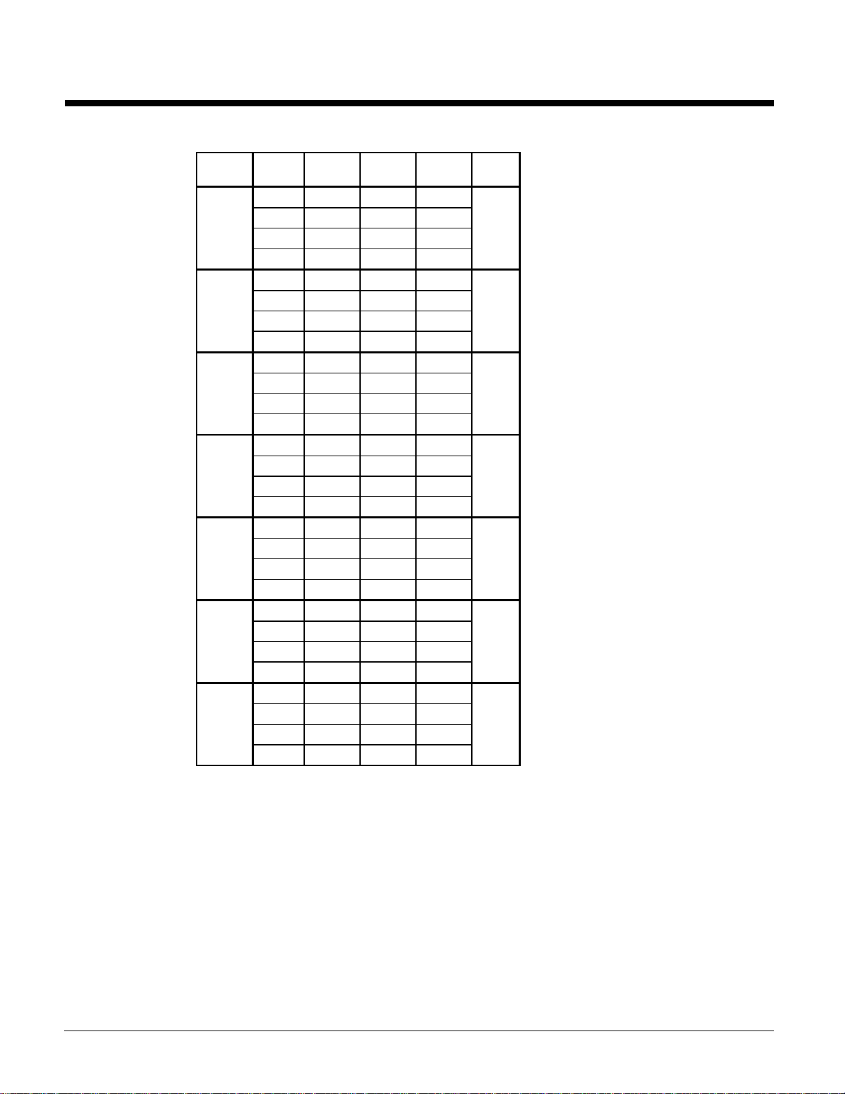
Table 11, 60 Hz, R-22
Unit Size % Load
070AS
075AS
080AS
085AS
090AS
095AS
100AS
100.00
75.00
50.00
25.00
100.00
75.00
50.00
25.00
100.00
75.00
50.00
25.00
100.00
75.00
50.00
25.00
100.00
75.00
50.00
25.00
100.00
75.00
50.00
25.00
100.00
75.00
50.00
25.00
Capacity
Tons
67.5 84.4 9.6
50.5 48.9 12.4
33.7 26.7 15.2
16.8 11.8 17.0
70.1 87.6 9.6
52.6 53.8 11.7
35 34.0 12.4
17.5 14.6 14.4
77.9 97.2 9.6
58.4 59.1 11.9
38.9 34 13.7
19.4 16.1 14.5
84.7 104.9 9.7
63.5 63.5 12
42.3 35.2 14.4
21.1 15.4 16.4
86.7 106 9.8
65 64.1 12.2
43.3 35.5 14.6
21.6 15.6 16.6
94 117.6 9.6
70.4 71.5 11.8
46.9 39.2 14.3
23.4 16.5 17.0
102.8 128.5 9.6
77.1 79.3 11.7
51.4 43.9 14.0
25.7 19.3 16.0
Power
Unit kW
EER IPLV
14.2
12.3
13.0
13.6
13.8
13.5
13.2
18
Notes: Certified in accordance with ARI Standard 550/590-98.
AGR 070A through 100A Product Manual AGR-3
Page 19

Sound Data
Table 12, AGR 070AS/AM - 100AS/AM Sound Pressure
Unit
Model
AGR070A
AGR075A
AGR080A
AGR085A
AGR090A
AGR095A
AGR100A
Note: Data at 30 ft. (9m) from side of unit.
63 125 250 500 1000 2000 4000 8000
65 65 64 64 62 56 54 54 66
66 67 65 65 62 56 55 55 67
66 68 65 65 62 56 56 55 67
67 69 66 65 62 56 56 55 67
67 69 66 65 62 56 56 55 67
68 69 67 66 63 58 58 56 68
69 70 68 66 63 58 58 56 68
Sound Pressure At 30 ft. From Sides Of Unit (dB)
Octave Band
Table 13, AGR 070AS/AM – 100AS/AM Sound Power
Unit
Model
AGR070A
AGR075A
AGR080A
AGR085A
AGR090A
AGR095A
AGR100A
Note: Per ARI Standard 370
63 125 250 500 1000 2000 4000 8000
92 92 91 91 89 83 81 81 93
93 94 92 92 89 83 82 82 94
93 95 92 92 89 83 83 82 94
94 96 93 92 89 83 83 82 94
94 96 93 92 89 83 83 82 94
95 96 94 93 90 85 86 83 95
96 97 95 93 90 85 86 83 95
Sound Power
Octave Band
Sound Pressure
Overall
A-Weighted
Sound Power
Overall
A-Weighted
Sound levels are as important as unit cost and efficiency, and must be addressed before to the start of
any development program. Efforts by McQuay design engineers to design chillers that are sensitive to
the sound requirements of the market have paid off.
Background Information
Sound is a vibration in an elastic medium and is essentially a pressure and particle displacement
phenomena. A vibrating body produces compression waves and as the waves are emitted from the
vibrating body, molecules are ultimately compressed. These values are transmitted through gas, liquid,
solidanything which is elastic or viscous.
The sound data provided in this section is presented with both sound pressure and sound power levels.
Sound power is the total sound energy radiated by a source per unit of time integrated over the surface
through which the sound is radiated. Sound power is a calculated quantity and cannot be measure d
directly like sound pressur e. Sound p ower i s not de p end ent on t he sur ro und ing envi ro nment o r d ist anc e
from the source, as is sound pressure.
Sound pressure varies with the distance from the source and is dependent on its surroundings. For
example, a brick wall located 10 feet from a unit will affect the sound pressure measurements
differently than a brick wall at 20 feet. Sound pressure is measured in decibels (dB), which is a
dimensionless ratio (on a logarithmic scale) between measured sound pressure and a reference sound
pressure level.
Sound Pressure Levels - Full Load
All sound pressure tables give the overall "A" weighted sound pressure levels which are considered
typical of what may be measured in a free field with a hand held sound meter, in the absence of any
nearby reflective surfaces. The sound pressure levels are measured at 30 feet (10 meters) from the side
of the unit at 100% unit load and ARI conditions. 95°F (35°C) ambient air temperature and 54/44°F
(12/7°C) evaporator water temperatures for air-cooled units.
Product Manual AGR-3 AGR 070A through 100A
19
Page 20

Sound Power Levels
Acoustical consultants may require sound power octave band data to perform a detailed acoustical
analysis. The tables that follow present sound power levels per ARI Standard 370, “Sound Rating
of Large Outdoor Refrigerating and Air Conditioning Equipment”. These standards were developed
to establish uniform methods of determining the sound power radiated by large outdoor and indoor
equipment. The aforementioned methods are based on providing sound power levels by octave
band and the overall ‘A’ weighted value. Measurements are taken over a prescribed area around the
unit and the data is mathematically calculated to give the sound power, dB.
Sound Reduction due to Distance from the Unit
The distance between a source of sound and the location of the sound measurement plays an
important role in minimizing sound problems. The equation below can be used to calculate the
sound pressure level
at any distance if the
sound power
tabulated in Table 14. Another way of determining the effect of distance is to work from sound
pressure only. “Q”, the directionality factor, is a dimensionless number that compensates for the
type of sound reflection from the source. For example, a unit sitting on a flat roof or ground with
no other reflective surfaces or attenuation due to grass, snow, etc., between source and receiver:
Q=2.
Figure 6, "Q" Definition, Plan View, Unit Located in Center
is known. Results for typical distances are
Uniform Spherical Radiation
Q=1 no reflecting surface
Uniform Hemispherical Radiation
Q=2 single reflecting surface
Uniform Radiation over ¼ of sphere
Q=4 two reflecting surfaces
Sound pressure can be calculated at any distance from the unit if the sound power is known.
Lp=Lw-(20 log r) + (10 log Q) - .5
Lp = sound pressure r = distance from unit in feet
Lw = sound power Q = directionality factor
With Q=1, Unit suspended in space (theoretical condition), the equation simplifies to:
Lp = Lw – (20)(log r) –0.5
With Q=2, for a unit sitting on a flat roof or ground with no adjacent vertical wall as a reflective
surface, the equation simplifies to:
Lp = Lw – (20)(log r) + 2.5
With Q=4 for a unit sitting on a flat roof or ground with one adjacent vertical wall as a reflective
surface, the equation simplifies to:
Lp = Lw – (20)(log r) + 5.5
The equations are reduced to table form in Table 14 for various distances and the two most usual
cases of “Q” type of location.
Table 14, dB Conversion of Sound Power to Pressure for Distance
Distance from Sound Source
ft. (m)
30 (9) 27.1 24.0
50 (15) 31.6 28.5
75 (23) 35.1 32.0
100 (30) 37.6 34.5
150 (46) 41.1 38.0
200 (61) 43.6 40.5
DB Reduction from Sound Power at the Source to Sound
Pressure at Referenced Distance
Q=2 Q=4
20
AGR 070A through 100A Product Manual AGR-3
Page 21

300 (91) 47.6 44.0
Figure 7, Sound Pressure Attenuation Due to Distance from Unit
Unit Orientation to Minimize Sound
The AGR reciprocating chiller’s sound is directional in nature allowing the contractor/engineer to
position the unit to minimize potential noise problems. Because the sound pressure levels are lower at
both ends of the unit than at the sides, the chiller should be oriented such that the control box end or end
opposite the control box faces the direction where the lowest sound level is required.
The control box end provides an excellent acoustic barrier to the compressor sound as it covers one full
end of the unit. The sound pressure levels at the control box end will be 4 dBA less than on the sides.
Figure 8, Sound Directionality
Sound Pressure Levels - Low Ambient Operation
Unit operation at a lower ambient temperature than 95°F will also result in lower sound pressure levels.
The sound pressure level will decrease 1 dBA for ambient temperatures between 85°F to 94°F (29.4°C
to 34.4°C), 2 dBA for ambient temperatures between 75°F to 84°F (23.9°C to 28.9°C), and 3 dBA for
ambient temperatures between 65°F to 74°F (18.3°C to 23.3°C).
Product Manual AGR-3 AGR 070A through 100A
21
Page 22

Pressure Drop Curves
Figure 9, Evaporator Pressure Drops
22
Unit
Size
070AS/AM 16.0 162 10.22 40.5 270 17.04 6.8 101 6.39
075AS/AM 9.6 168 10.60 24.0 280 17.67 4.3 105 6.62
080AS/AM 11.7 187 11.80 29.6 312 19.66 5.1 117 7.37
085AS/AM 13.5 203 12.81 33.3 338 21.35 5.9 127 8.00
090AS/AM 10.5 208 13.12 26.3 347 21.87 4.5 130 8.20
095AS/AM 12.0 226 14.26 30.0 377 23.76 5.2 141 8.91
100AS/AM 13.4 240 15.14 33.6 400 25.24 5.7 150 9.46
: Minimum and maximum flows are established to ensure the Delta-T for each unit size falls within the 6 - 16°F range for
Note
proper unit control. Contact factory for unit operation outside of minimum and maximum flows shown.
(ft) of Water
NOMINAL MAXIMUM MINIMUM
PD
Flow Flow Flow
(gpm) (lps)
PD
(ft) of Water
(gpm) (lps)
(ft) of Water
PD
(gpm) (lps)
AGR 070A through 100A Product Manual AGR-3
Page 23

Electrical Data
Table 15, 60 Hz, Single Point Power Electrical Data
AGR
Unit
Size
070AS
070AM
075AS
075AM
080AS
080AM
085AS
085AM
090AS
090AM
095AS
095AM
100AS
100AM
All Electrical Data notes are on page 26.
Minimum
Volts
208 322 3 400 1 2.50 450
230 300 3 350 1 2.50 400
380 190 3 3/0 1 2.00 250
460 153 3 2/0 1 1.50 200
575 114 3 #2 1 1.25 150
208 351 3 500 1 3.00 450
230 329 3 400 1 2.50 450
380 220 3 4/0 1 2.00 300
460 163 3 2/0 1 1.50 225
575 126 3 #1 1 1.50 150
208 384 6 3/0 2 2.00 500
230 373 3 500 1 3.00 500
380 240 3 250 1 2.50 300
460 187 3 3/0 1 2.00 250
575 151 3 2/0 1 1.50 200
208 411 6 4/0 2 2.00 500
230 408 6 4/0 2 2.00 500
380 256 3 300 1 2.50 350
460 206 3 4/0 1 2.00 250
575 171 3 3/0 1 2.00 225
208 411 6 4/0 2 2.00 500
230 408 6 4/0 2 2.00 500
380 256 3 300 1 2.50 350
460 206 3 4/0 1 2.00 250
575 171 3 3/0 1 2.00 225
208 461 6 250 2 2.00 600
230 458 6 4/0 2 2.00 600
380 269 3 300 1 2.50 350
460 220 3 4/0 1 2.00 300
575 176 3 3/0 1 2.00 225
208 501 6 250 2 2.00 700
230 498 6 250 2 2.00 700
380 279 3 300 1 2.50 350
460 231 3 250 1 2.00 300
575 180 3 3/0 1 2.00 250
Circuit
Ampacity
(MCA)
Field Wire Conduit Hub
Quantity
POWER SUPPLY
Wire
Gauge
Quantity
Nominal
Size
Max. Fuse
HACR Breaker
Size
or
Product Manual AGR-3 AGR 070A through 100A
23
Page 24

Table 16, 60 Hz, Compressor And Condenser Fan Motor Amp Draw
AGR
Unit
Size
070AS
070AM
075AS
075AM
080AS
080AM
085AS
085AM
090AS
090AM
095AS
095AM
100AS
100AM
Notes:
1. Part winding start is a special option on 380 – 575 volt units.
2. All Electrical Data notes are on page 26.
Volts
Rated Load Amps Locked Rotor Amps
Compressors Compressors
No.
1
208 122 135 7.8 4 30.5 N.A. N.A. 400 463
230 112 127 7.2 4 27.6 N.A. N.A. 340 340
380 65 87 4.1 4 20.0 365 365 N/A N/A
460 60 63 3.6 4 13.8 315 315 195 195
575 42 48 3.0 4 11.0 245 245 152 152
208 135 135 7.8 6 30.5 N.A. N.A. 463 463
230 127 127 7.2 6 27.6 N.A. N.A. 340 340
380 87 87 4.1 6 20.0 365 365 N/A N/A
460 63 63 3.6 6 13.8 315 315 195 195
575 48 48 3.0 6 11.0 245 245 152 152
208 135 162 7.8 6 30.5 N.A. N.A. 463 654
230 127 162 7.2 6 27.6 N.A. N.A. 340 654
380 87 103 4.1 6 20.0 365 740 N/A N/A
460 63 82 3.6 6 13.8 315 510 195 330
575 48 68 3.0 6 11.0 245 405 152 262
208 162 162 7.8 6 30.5 N.A. N.A. 654 654
230 162 162 7.2 6 27.6 N.A. N.A. 654 654
380 103 103 4.1 6 20.0 740 740 N/A N/A
460 82 82 3.6 6 13.8 510 510 330 330
575 68 68 3.0 6 11.0 405 405 262 262
208 162 162 7.8 6 30.5 N.A. N.A. 654 654
230 162 162 7.2 6 27.6 N.A. N.A. 654 654
380 103 103 4.1 6 20.0 740 740 N/A N/A
460 82 82 3.6 6 13.8 510 510 330 330
575 68 68 3.0 6 11.0 405 405 262 262
208 162 202 7.8 6 30.5 N.A. N.A. 654 654
230 162 202 7.2 6 27.6 N.A. N.A. 654 654
380 103 113 4.1 6 20.0 740 740 N/A N/A
460 82 93 3.6 6 13.8 510 510 330 330
575 68 72 3.0 6 11.0 405 405 262 262
208 202 202 7.8 6 30.5 N.A. N.A. 654 654
230 202 202 7.2 6 27.6 N.A. N.A. 654 654
380 113 113 4.1 6 20.0 740 740 N/A N/A
460 93 93 3.6 6 13.8 510 510 330 330
575 72 72 3.0 6 11.0 405 405 262 262
No.
2
Fan
Motors
(Each)
No. Of
Fan
Motors
Fan
Motors
(Each)
Across-The-Line Part Winding (1)
No. 1No. 2No. 1No. 2
24
AGR 070A through 100A Product Manual AGR-3
Page 25

Table 17, 60 Hz Single Point Power, Field Wiring Data
AGR
Unit
Size
070AS
070AM
075AS
075AM
080AS
080AM
085AS
085AM
090AS
090AM
095AS
095AM
100AS
100AM
All Electrical Data notes are on page 26.
Volts
208 335 # 4 - 400 MCM 400 250 - 500 MCM
230 335 # 4 - 400 MCM 400 250 - 500 MCM
380 335 # 4 - 400 MCM 250 #4 - 350 MCM
460 335 # 4 - 400 MCM 250 #4 - 350 MCM
575 335 # 4 - 400 MCM 150 #2 - 3/0
208 840 (2 qty.) 1/0 - 600 MCM 400 250 - 500 MCM
230 335 # 4 - 400 MCM 400 250 - 500 MCM
380 335 # 4 - 400 MCM 250 #4 - 350 MCM
460 335 # 4 - 400 MCM 250 #4 - 350 MCM
575 335 # 4 - 400 MCM 150 #2 - 3/0
208 840 (2 qty.) 1/0 - 600 MCM 400 250 - 500 MCM
230 840 (2 qty.) 1/0 - 600 MCM 400 250 - 500 MCM
380 335 # 4 - 400 MCM 250 #4 - 350 MCM
460 335 # 4 - 400 MCM 250 #4 - 350 MCM
575 335 # 4 - 400 MCM 250 #4 - 350 MCM
208 840 (2 qty.) 1/0 - 600 MCM 600 (2 qty.) 250 - 500 MCM
230 840 (2 qty.) 1/0 - 600 MCM 600 (2 qty.) 250 - 500 MCM
380 335 # 4 - 400 MCM 400 250 - 500 MCM
460 335 # 4 - 400 MCM 250 #4 - 350 MCM
575 335 # 4 - 400 MCM 250 #4 - 350 MCM
208 840 (2 qty.) 1/0 - 600 MCM 600 (2 qty.) 250 - 500 MCM
230 840 (2 qty.) 1/0 - 600 MCM 600 (2 qty.) 250 - 500 MCM
380 335 # 4 - 400 MCM 400 250 - 500 MCM
460 335 # 4 - 400 MCM 250 #4 - 350 MCM
575 335 # 4 - 400 MCM 250 #4 - 350 MCM
208 840 (2 qty.) 1/0 - 600 MCM 600 (2 qty.) 250 - 500 MCM
230 840 (2 qty.) 1/0 - 600 MCM 600 (2 qty.) 250 - 500 MCM
380 335 # 4 - 400 MCM 400 250 - 500 MCM
460 335 # 4 - 400 MCM 250 #4 - 350 MCM
575 335 # 4 - 400 MCM 250 #4 - 350 MCM
208 840 (2 qty.) 1/0 - 600 MCM 600 (2 qty.) 250 - 500 MCM
230 840 (2 qty.) 1/0 - 600 MCM 600 (2 qty.) 250 - 500 MCM
380 335 # 4 - 400 MCM 400 250 - 500 MCM
460 335 # 4 - 400 MCM 250 #4 - 350 MCM
575 335 # 4 - 400 MCM 250 #4 - 350 MCM
Terminal
Amps
Wiring to Standard Wiring to Optional
Power Block Non-Fused Disconnect Switch
Connector Wire Range
(Copper Wire Only)
Terminal
Amps
Connector Wire Range
(Copper Wire Only)
Product Manual AGR-3 AGR 070A through 100A
25
Page 26

Notes for “Electrical Data Single Point” Power:
1. Unit wire size ampacity (MCA) is equal to 125% of the largest compressor-motor RLA plus 100%
of RLA of all other loads in the circuit including the control transformer.
2. The control transformer is furnished. A separate 115v power supply can be used if desired.
3. If a separate 115V power supply is used for the control circuit, then the wire sizing amps is 10
amps for all unit sizes.
4. Recommended power lead wire sizes for 3 conductors per conduit are based on 100% conductor
ampacity in accordance with NEC. Nominal voltage drop has been included. It is recommended
that power leads be kept short. All terminal block connections must be made with copper (type
THW) wire.
5. “Recommended Fuse Sizes or HACR breaker size” is selected at approximately 150% to 175% of
the largest compressor RLA, plus 100% of all other loads in the circuit.
6. “Maximum Fuse or HACR breaker size” is selected based on 225% of the largest compressor RLA,
plus 100% of all other loads in the circuit.
7. The recommended power lead wire sizes are based on an ambient temperature of 86°F (30°C).
Ampacity correction factors must be applied for other ambient temperatures. Refer to the National
Electrical Code Handbook.
8. Must be electrically grounded according to national and local electrical codes.
9. MCA may vary slightly due to fan motor options such as SpeedTrol.
Voltage Limitations:
Within ± 10 percent of unit nameplate rating.
Notes for “Compressor and Condenser Fan Amp Draw”:
1. Compressor RLA values are for wiring sizing purposes only and may be higher than nominal
operating current draw at rated capacity.
2. If unit is equipped with SpeedTrol condenser fan motors, the first motor on each refrigerant circuit
is a single phase, 1hp motor, with a FLA of 2.8 amps at 460 volts and 5.6 amps at 208, 230 volts
and LRA of 7.3 amps at 460 volts and 14.5 amps at 208, 230 volts.
3. Compressor LRA for reduced inrush start are for the first winding of part-winding start only.
Notes for “Field Wiring Data”:
1. The standard unit requires a single disconnect to supply electrical power to the unit. Power supply
must either be fused or use a HACR type circuit breaker.
2. Multiple point power connection for field wiring is available as an option. Two power terminal
blocks are supplied in the unit, one for each system in the unit. Each power terminal block supplies
both compressor and fan motor power for each system. The control transformer is furnished and
connected to the system #1 power terminal block.
3. All field wiring to unit power block or optional non-fused disconnect switch must be copper.
4. All field wire size values given in table apply to 75°C rated wire per NEC.
26
AGR 070A through 100A Product Manual AGR-3
Page 27

Figure 10, Typica l Field Wiring with MicroTech Controller
See Note 3 for “Electrical Data Single Point Power” on page 26
Product Manual AGR-3 AGR 070A through 100A
27
Page 28

Figure 11, Typical Field Wiring Diagram with UNT Controller
28
See note 3 for “Electrical Data Single Point Power” on page 26
AGR 070A through 100A Product Manual AGR-3
Page 29

Physical Data
AGR-AS, Packaged Chiller
Table 18, AGR 070AS – AGR 085AS
PHYSICAL DATA
STANDARD EFFICIENCY
BASIC DATA Ckt.1 Ckt.2 Ckt.1 Ckt.2 Ckt.1 Ckt.2 Ckt.1 Ckt.2
Unit Capacity @ ARI Conditions (1), Tons (kW) 67.5 (237.6) 70.1 (246.7) 77.9 (273.9) 84.7 (298.1)
Number Of Refrigerant Circuits 2222
Unit Operating Charge, R-22, lbs. (kg) 60 (27.2) 84 (38.1) 84 (38.1) 86 (39.9) 86 (39.9) 86 (39.9) 86 (39.9) 86 (39.9)
Unit Operating Charge, R-134a, , lbs. (kg) 63 (28.6) 88 (40.0) 88 (40.0) 90 (41.9) 90 (41.9) 90 (41.9) 90 (41.9) 90 (41.9)
Cabinet Dimensions, LxWxH, In. 94.0 x 88.2 x 96.2 136.4 x 88.2 x 96.2 136.4 x 88.2 x 96.2 136.4 x 88.2 x 96.2
Cabinet Dimensions, LxWxH, (mm) 2388 x 2241 x 2444 3463 x 2241 x 2444 3463 x 2241 x 2444 3463 x 2241 x 2444
Unit Operating Weight, Lbs. (kg) 4755 (2154) 5506 (2497) 5740 (2604) 5921 (2686)
Unit Shipping Weight, Lbs. (kg) 4650 (2106) 5359 (2431) 5593 (2537) 5774 (2619)
Add'l Weight If Copper Finned Coils, Lbs. (kg) 830 (375) 1245 (565) 1245 (565) 1245 (565)
COMPRESSORS
Type Semi-Hermetic Semi-Hermetic Semi-Hermetic Semi-Hermetic
Nominal Horsepower 35 40 40 40 40 50 50 50
Number Of Cylinders Per Compressor 66666888
Oil Charge Per Compressor, oz. 140 255 255 255 255 255 255 255
Oil Charge Per Compressor, (g) (3969) (7229) (7229) (7229) (7229) (7229) (7229) (7229)
CAPACITY REDUCTION STEPS - PERCENT OF COMPRESSOR DISPLACEMENT
Standard Staging - Circuit #1 in Lead 0-16-33-49-67 0-17-33-50-67 0-15-42-58-73 0-25-50-63-75
Standard Staging - Circuit #2 in Lead 0-17-33-51-67 0-17-33-50-67 0-27-42-56-71 0-25-50-63-75
CONDENSERS - HIGH EFFICIENCY FIN AND TUBE TYPE WITH INTEGRAL SUBCOOLING
Coil Face Area, sq. ft. 58 58 87 87 87 87 87 87
Coil Face Area, (m2) (5.4) (5.4) (8.1) (8.1) (8.1) (8.1) (8.1) (8.1)
Finned Height x Finned Length, In. 100x 83.5 100x 83.5 100x125.3 100x125.3 100x125.3 100x125.3 100x125.3 100x125.3
Finned Height x Finned Length, (mm)
Fins Per Inch x Rows Deep 16 x 3 16 x 3 16 x 3 16 x 3 16 x 3 16 x 3 16 x 3 16 x 3
Pumpdown capacity @ 90% lbs. (kg) 108 (49) 108 (49) 162 (73) 162 (73) 162 (73) 162 (73) 162 (73) 162 (73)
Maximum Relief Valve Pressure Setting, psig (kPa) 450 (3103) 450 (3103) 450 (3103) 450 (3103) 450 (3103) 450 (3103) 450 (3103) 450 (3103)
CONDENSER FANS – DIRECT DRIVE PROPELLER TYPE
Number Of Fans - Fan Diameter, In. (mm) 4 - 28 (712) 6 - 28 (712) 6 - 28 (712) 6 - 28 (712)
Number Of Motors - HP (kW) 4 - 2.0 (1.5) 6 - 2.0 (1.5) 6 - 2.0 (1.5) 6 - 2.0 (1.5)
Fan And Motor RPM, 60Hz 1140 1140 1140 1140
60 Hz Fan Tip Speed, fpm (m/Sec) 8357 (35.4) 8357 (35.4) 8357 (35.4) 8357 (35.4)
60 Hz Total Unit Airflow, cfm (m3/sec) 40800 (19.3) 61200 (28.9) 61200 (28.9) 61200 (28.9)
DIRECT EXPANSION EVAPORATOR - BAFFLED SHELL AND THRU-TUBE
Diameter, in. - Length, ft. 12.75- 4 12.75 - 5.5 12.75 - 5.5 12.75 - 5.5
Diameter, (mm) – Length, (mm) 324 - 1220 324 - 1676 324 - 1676 324 - 1676
Water Volume, gallons, (l) 12.8 (48.5) 17.6 (66.6) 17.6 (66.6) 17.6 (66.6)
Water Side Design Pressure, psig (kPa) 225 (1552) 225 (1552) 225 (1552) 225 (1552)
Refrigerant Design Pressure, psig (kPa) 225 (1552) 225 (1552) 225 (1552) 225 (1552)
Water Inlet / Outlet Victaulic Connections, In. (mm) 5 (141.3) 5 (141.3) 5 (141.3) 5 (141.3)
Drain - NPT int, In. (mm) .375 (9.5) .375 (9.5) .375 (9.5) .375 (9.5)
Vent - NPT int, In. (mm) .375 (9.5) .375 (9.5) .375 (9.5) .375 (9.5)
NOTE: Nominal capacity based on 95°F ambient air and 54°F/44°F water range, R-22.
070AS 075AS 080AS 085AS
-83-100 -83-100 -86-100 -88-100
-84-100 -83-100 -85-100 -88-100
2032 x
2121
2032 x
2121
AGR MODEL NUMBER
2540 x
3183
2540 x
3183
2540 x
3183
2540 x
3183
2540 x
3183
2540 x
3183
Product Manual AGR-3 AGR 070A through 100A
29
Page 30

Table 19, AGR 090AS – AGR 100AS
PHYSICAL DATA AGR MODEL NUMBER
STANDARD EFFICIENCY 090AS 095AS 100AS
BASIC DATA Ckt.1 Ckt.2 Ckt.1 Ckt.2 Ckt.1 Ckt.2
Unit Capacity @ ARI Conditions (1), Tons (kW) 86.7 (305.2) 94.0 (330.1) 102.8 (359.8)
Number Of Refrigerant Circuits 2 2 2
Unit Operating Charge, R-22, lbs.(kg) 90 (40.8) 90 (40.8) 90 (40.8) 92 (41.7) 92 (41.7) 92 (41.7)
Unit Operating Charge, R-134a, lbs.(kg) 94 (42.8) 94 (42.8) 94 (42.8) 96 (43.7) 96 (43.7) 96 (43.7)
Cabinet Dimensions, LxWxH, In. 136.4 x 88.2 x 96.2 136.4 x 88.2 x 96.2 136.4 x 88.2 x 96.2
Cabinet Dimensions, LxWxH, (mm) 3463 x 2241 x 2444 3463 x 2241 x 2444 3463 x 2241 x 2444
Unit Operating Weight, Lbs. (kg) 6184 (2805) 6194 (2810) 6194 (2810)
Unit Shipping Weight, Lbs. (kg) 6008 (2725) 6018 (2730) 6018 (2730)
Add'l Weight If Copper Finned Coils, Lbs. (kg) 1245 (565) 1245 (565) 1245 (565)
COMPRESSORS
Type Semi-Hermetic Semi-Hermetic Semi-Hermetic
Nominal Horsepower 50 50 50 60 60 60
Number Of Cylinders Per Compressor 888888
Oil Charge Per Compressor, oz. 255 255 255 255 255 255
Oil Charge Per Compressor, (g) (7229) (7229) (7229) (7229) (7229) (7229)
CAPACITY REDUCTION STEPS - PERCENT OF COMPRESSOR DISPLACEMENT
Standard Staging - Circuit #1 in Lead 0-25-50-63-75 0-23-50-61-75 0-25-50-63-75
Standard Staging - Circuit #2 in Lead 0-25-50-63-75 0-27-50-64-75 0-25-50-63-75
CONDENSERS - HIGH EFFICIENCY FIN AND TUBE TYPE WITH INTEGRAL SUBCOOLING
Coil Face Area, sq. ft. 87 87 87 87 87 87
Coil Face Area, (m2) (8.1) (8.1) (8.1) (8.1) (8.1) (8.1)
Finned Height x Finned Length, In. 100x125.3 100x125.3 100x125.3 100x125.3 100x125.3 100x125.3
Finned Height x Finned Length, (mm)
Fins Per Inch x Rows Deep 16 x 3 16 x 3 16 x 3 16 x 3 16 x 3 16 x 3
Pumpdown capacity @ 90% lbs. (kg) 162 (73) 162 (73) 162 (73) 162 (73) 162 (73) 162 (73)
Maximum Relief Valve Pressure Setting, psig (kPa) 450 (3103) 450 (3103) 450 (3103) 450 (3103) 450 (3103) 450 (3103)
CONDENSER FANS – DIRECT DRIVE PROPELLER TYPE
Number Of Fans - Fan Diameter, in. (mm) 6 - 28 (712) 6 - 28 (712) 6 - 28 (712)
Number Of Motors - HP (kW) 6 - 2.0 (1.5) 6 - 2.0 (1.5) 6 - 2.0 (1.5)
Fan And Motor RPM, 60Hz 1140 1140 1140
60 Hz Fan Tip Speed, fpm (m/sec) 8357 (35.4) 8357 (35.4) 8357 (35.4)
60 Hz Total Unit Airflow, cfm (m3/sec) 61200 (28.9) 61200 (28.9) 61200 (28.9)
DIRECT EXPANSION EVAPORATOR - BAFFLED SHELL AND THRU-TUBE
Diameter, in. - Length, ft. 14 - 5.5 14 - 5.5 14 - 5.5
Diameter, (mm) – Length, (mm) 356 - 1676 356 - 1676 356 - 1676
Water Volume, gallons, (l) 21.2 (80.3) 21.2 (80.3) 21.2 (80.3)
Water Side Design Pressure, psig (kPa) 225 (1552) 225 (1552) 225 (1552)
Refrigerant Design Pressure, psig (kPa) 225 (1552) 225 (1552) 225 (1552)
Water Inlet / Outlet Victaulic Connections, In. (mm) 5 (141.3) 5 (141.3) 5 (141.3)
Drain - NPT int, In. (mm) .375 (9.5) .375 (9.5) .375 (9.5)
Vent - NPT int, In. (mm) .375 (9.5) .375 (9.5) .375 (9.5)
NOTE: Nominal capacity based on 95°F ambient air and 54°F/44°F water range.
-88-100 -86-100 -88-100
-88-100 -89-100 -88-100
2540 x
3183
2540 x
3183
2540 x
3183
2540 x
3183
2540 x
3183
2540 x
3183
30
AGR 070A through 100A Product Manual AGR-3
Page 31

AGR-AM, Remote Evaporator
Table 20, AGR 070AM - 085AM
PHYSICAL DATA AGR MODEL NUMBER
STANDARD EFFICIENCY 070A M 075AM 080AM 085AM
OUTDOOR UNIT BASIC DATA Ckt.1 Ckt.2 Ckt.1 Ckt.2 Ckt.1 Ckt.2 Ckt.1 Ckt.2
Number Of Refrigerant Circuits 2222
Unit Operating Charge, R-22, lbs. (kg) 60 (27.2) 84 (38.1) 84 (38.1) 86 (39.9) 86 (39.9) 86 (39.9) 86 (39.9) 86 (39.9)
Unit Operating Charge, R-134a, , lbs. (kg) 63 (28.6) 88 (40.0) 88 (40.0) 90 (41.9) 90 (41.9) 90 (41.9) 90 (41.9) 90 (41.9)
Cabinet Dimensions, LxWxH, In. 94.0 x 88.2 x 96.2 136.4 x 88.2 x 96.2 136.4 x 88.2 x 96.2 136.4 x 88.2 x 96.2
Cabinet Dimensions, LxWxH, (mm) 2388 x 2241 x 2444 3463 x 2241 x 2444 3463 x 2241 x 2444 3463 x 2241 x 2444
Unit Operating Weight, Lbs. (kg) 3978 (1802) 4509 (2043) 4743 (2149) 4924 (2331)
Unit Shipping Weight, Lbs. (kg) 3855 (1746) 4384 (1986) 4618 (2092) 4799 (2174)
Add'l Weight If Copper Finned Coils, Lbs. (kg) 830 (375) 1245 (565) 1245 (565) 1245 (565)
COMPRESSORS
Type Semi-Hermetic Semi-Hermetic Semi-Hermetic Semi-Hermetic
Nominal Horsepower 35 40 40 40 40 50 50 50
Number Of Cylinders Per Compressor 66666888
Oil Charge Per Compressor, oz. 140 255 255 255 255 255 255 255
Oil Charge Per Compressor, (g) (3969) (7229) (7229) (7229) (7229) (7229) (7229) (7229)
CAPACITY REDUCTION STEPS - PERCENT OF COMPRESSOR DISPLACEMENT
Standard Staging - Circuit #1 in Lead 0-16-33-49-67 0-17-33-50-67 0-15-42-58-73 0-25-50-63-75
Standard Staging - Circuit #2 in Lead 0-17-33-51-67 0-17-33-50-67 0-27-42-56-71 0-25-50-63-75
CONDENSERS - HIGH EFFICIENCY FIN AND TUBE TYPE WITH INTEGRAL SUBCOOLING
Coil Face Area,Sq. Ft. 5858878787878787
Coil Face Area, (m2) (5.4) (5.4) (8.1) (8.1) (8.1) (8.1) (8.1) (8.1)
Finned Height x Finned Length, In. 100x 83.5 100x 83.5 100x125.3 100x125.3 100x125.3 100x125.3 100x125.3 100x125.3
Finned Height x Finned Length, (mm)
Fins Per Inch x Rows Deep 16 x 3 16 x 3 16 x 3 16 x 3 16 x 3 16 x 3 16 x 3 16 x 3
Pumpdown capacity @ 90% Lbs. (kg) 108 (49) 108 (49) 162 (73) 162 (73) 162 (73) 162 (73) 162 (73) 162 (73)
Maximum Relief Valve Pressure Setting, psig (kPa) 450 (3103) 450 (3103) 450 (3103) 450 (3103) 450 (3103) 450 (3103) 450 (3103) 450 (3103)
CONDENSER FANS - DIRECT DRIVE PROPELLER TYPE
Number Of Fans - Fan Diameter, In. (mm) 4 - 28 (712) 6 - 28 (712) 6 - 28 (712) 6 - 28 (712)
Number Of Motors - HP (kW) 4 - 2.0 (1.5) 6 - 2.0 (1.5) 6 - 2.0 (1.5) 6 - 2.0 (1.5)
Fan And Motor RPM, 60Hz 1140 1140 1140 1140
60 Hz Fan Tip Speed, FPM (M/Sec) 8357 (35.4) 8357 (35.4) 8357 (35.4) 8357 (35.4)
60 Hz Total Unit Airflow, CFM (M3/sec) 40800 (19.3) 61200 (28.9) 61200 (28.9) 61200 (28.9)
REMOTE DIRECT EXPANSION EVAPORATOR - BAFFLED SHELL AND -TUBE
Model Number, CDE 1204-1 1255-1 1255-1 1255-1
Operating Weight Lbs (kg) 777 (352) 997 (452) 997 (452) 997 (452)
Shipping Weight Lbs (kg) 745 (338) 925 (420) 925 (420) 925 (420)
Diameter, in. - Length, Ft. 12.75- 04 12.75 - 5.5 12.75 - 5.5 12.75 - 5.5
Diameter, (mm) - Length, (mm) 324 - 1220 324 - 1676 324 - 1676 324 - 1676
Water Volume, Gallons, (L) 12.8 (48.5) 17.6 (66.6) 17.6 (66.6) 17.6 (66.6)
Refrigerant Volume, cu. Ft. (cu. m.) 1.25 (.0353) 1.69 (.0478) 1.69 (.0478) 1.69 (.0478)
Operating Charge, Per System, Lbs (kg) (Note 1) 2.8 (1.27) 3.8 (1.72) 3.8 (1.72) 3.8 (1.72)
Water Side Design Pressure, psig (kPa) 225 (1552) 225 (1552) 225 (1552) 225 (1552)
Refrigerant Design Pressure, psig (kPa) 225 (1552) 225 (1552) 225 (1552) 225 (1552)
Water Inlet / Outlet Victaulic Connections, In. (mm) 5 (141.3) 5 (141.3) 5 (141.3) 5 (141.3)
Drain - NPT int, In. (mm) .375 (9.5) .375 (9.5) .375 (9.5) .375 (9.5)
Vent - NPT int, In. (mm) .375 (9.5) .375 (9.5) .375 (9.5) .375 (9.5)
NOTES:
1. Includes evaporator. Does not include suction and liquid line charge. Outdoor unit and evaporator are shipped with R-22 holding charge.
-83-100 -83-100 -86-100 -88-100
-84-100 -83-100 -85-100 -88-100
2032 x
2121
2032 x
2121
2540 x
3183
2540 x
3183
2540 x
3183
2540 x
3183
2540 x
3183
2540 x
3183
Product Manual AGR-3 AGR 070A through 100A
31
Page 32

Table 21, AGR 090AM - 100AM
PHYSICAL DATA AGR MODEL NUMBER
STANDARD EFFICIENCY 090A M 095AM 100AM
OUTDOOR UNIT BASIC DATA Ckt.1 Ckt.2 Ckt.1 Ckt.2 Ckt.1 Ckt.2
Number Of Refrigerant Circuits 2 2 2
Unit Operating Charge, R-22, lbs.(kg) 90 (40.8) 90 (40.8) 90 (40.8) 90 (40.8) 92 (41.7) 92 (41.7)
Unit Operating Charge, R-134a, lbs.(kg) 94 (42.8) 94 (42.8) 94 (42.8) 94 (42.8) 94 (42.8) 94 (42.8)
Cabinet Dimensions, LxWxH, In. 136.4 x 88.2 x 96.2 136.4 x 88.2 x 96.2 136.4 x 88.2 x 96.2
Cabinet Dimensions, LxWxH, (mm) 3463 x 2241 x 2444 3463 x 2241 x 2444 3463 x 2241 x 2444
Unit Operating Weight, Lbs. (kg) 5858 (2654) 5068 (2296) 5068 (2296)
Unit Shipping Weight, Lbs. (kg) 4933 (2235) 4943 (2239) 4943 (2239)
Add'l Weight If Copper Finned Coils, Lbs. (kg) 1245 (565) 1245 (565) 1245 (565)
COMPRESSORS
Type Semi-Hermetic Semi-Hermetic Semi-Hermetic
Nominal Horsepower 50 50 50 60 60 60
Number Of Cylinders Per Compressor 888888
Oil Charge Per Compressor, oz. 255 255 255 255 255 255
Oil Charge Per Compressor, (g) (7229) (7229) (7229) (7229) (7229) (7229)
CAPACITY REDUCTION STEPS - PERCENT OF COMPRESSOR DISPLACEMENT
Standard Staging - Circuit #1 in Lead 0-25-50-63-75 0-23-50-61-75 0-25-50-63-75
Standard Staging - Circuit #2 in Lead 0-25-50-63-75 0-27-50-64-75 0-25-50-63-75
CONDENSERS - HIGH EFFICIENCY FIN AND TUBE TYPE WITH INTEGRAL SUBCOOLING
Coil Face Area,Sq. Ft. 878787878787
Coil Face Area, (m2) (8.1) (8.1) (8.1) (8.1) (8.1) (8.1)
Finned Height x Finned Length, In. 100x125.3 100x125.3 100x125.3 100x125.3 100x125.3 100x125.3
Finned Height x Finned Length, (mm)
Fins Per Inch x Rows Deep 16 x 3 16 x 3 16 x 3 16 x 3 16 x 3 16 x 3
Pumpdown capacity @ 90% Lbs. (kg) 162 (73) 162 (73) 162 (73) 162 (73) 162 (73) 162 (73)
Maximum Relief Valve Pressure Setting, psig (kPa) 450 (3103) 450 (3103) 450 (3103) 450 (3103) 450 (3103) 450 (3103)
CONDENSER FANS - DIRECT DRIVE PROPELLER TYPE
Number Of Fans - Fan Diameter, In. (mm) 6 - 28 (712) 6 - 28 (712) 6 - 28 (712)
Number Of Motors - HP (kW) 6 - 2.0 (1.5) 6 - 2.0 (1.5) 6 - 2.0 (1.5)
Fan And Motor RPM, 60Hz 1140 1140 1140
60 Hz Fan Tip Speed, FPM (M/Sec) 8357 (35.4) 8357 (35.4) 8357 (35.4)
60 Hz Total Unit Airflow, CFM (M3/sec) 61200 (28.9) 61200 (28.9) 61200 (28.9)
REMOTE DIRECT EXPANSION EVAPORATOR - BAFFLED SHELL AND -TUBE
Model Number, CDE 1455-1 1455-1 1455-1
Operating Weight Lbs (kg) 1126 (511) 1126 (511) 1126 (511)
Shipping Weight Lbs (kg) 1025 (465 1025 (465 1025 (465
Diameter, in. - Length, Ft. 14 - 5.5 14 - 5.5 14 - 5.5
Diameter, (mm) - Length, (mm) 356 - 1676 356 - 1676 356 - 1676
Water Volume, Gallons, (L) 21.2 (80.3) 21.2 (80.3) 21.2 (80.3)
Refrigerant Volume, cu. Ft. (cu. m.) 2.33 (.0659) 2.33 (.0659) 2.33 (.0659)
Operating Charge, Per System, Lbs (kg) (Note 1) 5.2 (2.36) 5.2 (2.36) 5.2 (2.36)
Water Side Design Pressure, psig (kPa) 225 (1552) 225 (1552) 225 (1552)
Refrigerant Design Pressure, psig (kPa) 225 (1552) 225 (1552) 225 (1552)
Water Inlet / Outlet Victaulic Connections, In. (mm) 5 (141.3) 5 (141.3) 5 (141.3)
Drain - NPT int, In. (mm) .375 (9.5) .375 (9.5) .375 (9.5)
Vent - NPT int, In. (mm) .375 (9.5) .375 (9.5) .375 (9.5)
NOTES:
1. Includes evaporator. Does not include suction and liquid line charge. Outdoor unit and evaporator are shipped with
R-22 holding charge.
-88-100 -86-100 -88-100
-88-100 -89-100 -88-100
2540 x
3183
2540 x
3183
2540 x
3183
2540 x
3183
2540 x
3183
2540 x
3183
32
AGR 070A through 100A Product Manual AGR-3
Page 33

Dimensional Data
Packaged Chiller, AGR-AS
Figure 12, Dimensions AGR 070AS
AGR
Model
Number
070AS
Dimensions
A B C D E F X Y Z lb (kg) lb (kg)
96.2
(2444)
91.7
(2329)
60.0
(1525)
23.9
(607)
4.3
(108)
16.0
(406)
Center of Gravity
inch (mm)
45.0
(1143)
Product Manual AGR-3 AGR 070A through 100A
41.8
(1062)
Operating Shipping
38.8
(986)
(2155)
4755
Weights
4650
(2107)
Additional Weight
with Copper
Fin Coils lb (kg)
830
(375)
33
Page 34

Figure 13, Dimensions AGR 075AS through 100AS
34
AGR
Model
Number
075AS
080AS
085AS
090AS
095AS
100AS
Dimensions
A C D E F X Y Z lb. (kg) lb. (kg)
96.2
(2444)
96.2
(2444)
96.2
(2444)
96.2
(2444)
96.2
(2444)
96.2
(2444)
99.2
(2520)
99.2
(2520)
99.2
(2520)
99.2
(2520)
99.2
(2520)
99.2
(2520)
45.2
(1148)
45.2
(1148)
45.2
(1148)
45.2
(1148)
45.2
(1148)
45.2
(1148)
4.4
(112)
4.4
(112)
4.4
(112)
3.8
(96)
3.8
(96)
3.8
(96)
17.5
(444)
17.5
(444)
17.5
(444)
17.5
(444)
17.5
(444)
17.5
(444)
Center of Gravity
inch (mm)
60.4
(1534)
60.4
(1534)
60.4
(1534)
60.4
(1534)
60.4
(1534)
60.4
(1534)
42.2
(1072)
41.5
(1054)
40.8
(1036)
42.0
(1067)
42.0
(1067)
42.0
(1067)
37.3
(947)
36.9
(937)
36.2
(919)
36.8
(935)
35.4
(899)
35.4
(899)
Weights
Operating Shipping
5506
(2495)
5740
(2605)
5920
(2685)
6185
(2805)
6195
(2810)
6195
(2810)
AGR 070A through 100A Product Manual AGR-3
5360
(2429)
5595
(2540)
5775
(2620)
6010
(2725)
6020
(2730)
6020
(2730)
Additional Weight
for Copper
Fin Coils lb (kg)
1245
(565)
1245
(565)
1245
(565)
1245
(565)
1245
(565)
1245
(565)
Page 35

Remote Evaporator, AGR-AM
Figure 14, AGR 070AM
AGR
MODEL
NUMBER
070AM 96.2 (1444) 49.34 (1253) 20.88 (597) 23.52 (597) 9.34 (237) 20.88 (597) 25.52 (648)
AGR
MODEL
NUMBER
070AM 44.0 (1118) 37.5 (953) 43.0 (1092) 4090 (1855) 3980 (1805) 830 (375) 2 1/8 1 1/8
ACDEFGH
CENTER OF GRAVITY UNIT WEIGHTS ADD'L FOR SUCTION LIQUID
inch (mm) lb (kgs) COPPER FIN CONN. CONN.
X Y Z OPERATING SHIPPING lb (kgs) in. in
COMPRESSOR # 1 (SUCTION #1) COMPRESSOR # 2 (SUCTION #2)
inch (mm) inch (mm)
Product Manual AGR-3 AGR 070A through 100A
35
Page 36

Figure 15, AGR 075AM - AGR 100AM
36
AGR
MODEL
NUMBER
075AM 96.2 (2444) 88.5 (2248) 20.9 (531) 25.5 (648) 48.5 (1232) 20.9 (531) 25.5 (648)
080AM 96.2 (2444) 88.5 (2248) 20.9 (531) 25.5 (648) 49.0 (1245) 23.9 (608) 27.8 (707)
085AM 96.2 (2444) 86.0 (2184) 23.9 (608) 27.8 (707) 49.0 (1245) 23.9 (608) 27.8 (707)
090AM 96.2 (2444) 86.0 (2184) 23.9 (608) 27.8 (707) 49.0 (1245) 23.9 (608) 27.8 (707)
095AM 96.2 (2444) 86.0 (2184) 23.9 (608) 27.8 (707) 49.0 (1245) 23.9 (608) 27.8 (707)
100AM 96.2 (2444) 86.0 (2184) 23.9 (608) 27.8 (707) 49.0 (1245) 23.9 (608) 27.8 (707)
AGR
MODEL
NUMBER
075AM 59.8 (1519) 37.5 (953) 41.5 (1054) 4670 (2118) 4510 (2045) 1245 (565) 2 1/8 1 1/8
080AM 59.8 (1519) 36.9 (937) 40.8 (1036) 4905 (2224) 4745 (2152) 1245 (565) 2 1/8,2 5/8 1 1/8
085AM 59.8 (1519) 36.3 (922) 39.9 (1013) 5089 (2308) 4925 (2234) 1245 (565) 2 5/8 1 1/8
090AM 59.8 (1519) 37.3 (947) 40.9 (1039) 5224 (2370) 5060 (2295) 1245 (565) 2 5/8 1 1/8
095AM 59.8 (1519) 37.3 (947) 39.3 (998) 5234 (2374) 5070 (2300) 1245 (565) 2 5/8 1 1/8
100AM 59.8 (1519) 37.3 (947) 39.3 (998) 5238 (2376) 5070 (2300) 1245 (565) 2 5/8 1 1/8
ACDE F G H
CENTER OF GRAVITY UNIT WEIGHTS
X Y Z OPERATING SHIPPING
COMPRESSOR # 1 (SUCTION #1) COMPRESSOR # 2 (SUCTION #2)
inch (mm) lb (kgs)
inch (mm) inch (mm)
ADD'L FOR
COPPER FIN
lb (kgs)
SUCTION
CONN.
LIQUID
CONN.
in
AGR 070A through 100A Product Manual AGR-3
in
Page 37

CDE Evaporators
Figure 16, CDE Evaporators
CDE USED ON WATER CONNECTION REFRIGERANT CONNECTION
MODEL AGR-AM inch (mm) inch (mm)
NUMBER MODEL C L P T M N
CDE-1204-1 070 36.0 (914) 9.5 (241) 5.0 (127) 7.0 (178) 2 1/8 (54) 1 3/8 (35)
CDE-1255-1 075, 080, 085 54.0 (1372) 11.0 (278) 5.0 (127) 7.0 (178) 2 1/8 (54) 1 3/8 (35)
CDE-1455-1 090, 095, 100 54.0 (1372) 11.0 (278) 5.0 (127) 7.0 (178) 2 1/8 (54) 1 3/8 (35)
CDE DIMENSIONAL DATA
MODEL inch (mm)
NUMBER A B D E F G
CDE-1204-1 53.5 (1359) 17.5 (445) 8.8 (224) 17.5 (445) 12.1 (307) 2.3 (58)
CDE-1255-1 71.5 (1816) 17.5 (445) 8.8 (224) 19.0 (483) 12.1 (307) 3.0 (76)
CDE-1455-1 71.5 (1816) 19.1 (485) 8.8 (224) 19.0 (483) 12.1 (307) 3.0 (76)
CDE
MODEL
NUMBER K R S U V W BB
CDE-1204-1 3.0 (76) 50.0 (1270) 52.0 (1321) 1.8 (45) 2.8 (71) 16.0 (406 14.0 (356)
CDE-1255-1 3.0 (76) 68.0 (1727) 70.0 (1778) 1.8 (45) 2.8 (71) 16.0 (406) 14.0 (356)
CDE-1455-1 3.0 (76) 68.0 (1727) 70.0 (1778) 1.8 (45) 2.8 (71) 17.6 (447) 14.0 (356)
DIMENSIONAL DATA
inch (mm)
Product Manual AGR-3 AGR 070A through 100A
37
Page 38

Application Data
AIR
Unit Placement
AGR units are for outdoor applications and
can be mounted either on a roof or at ground
level. For roof mounted applications, install
the unit on a steel channel or I-beam frame
to support the unit above the roof. For
ground level applications, install the unit on
a substantial base that will not settle. A onepiece concrete slab with footings extended
below the frost line is recommended. Be
sure the foundation is level within
1/2"(13mm) over its length and width. The
foundation must be strong enough to
support the weights listed in the Physical
Data Tables.
Clearances
Do not block the flow of air to and
from the condenser coil. Restricting
airflow or allowing air recirculation
will result in a decrease in unit
performance and efficiency because
discharge pressures are increased.
There must be no obstruction above
the unit that would deflect discharge
air downward where it could be
recirculated back to the inlet of the
condenser coil. The condenser fans are
propeller type and will not operate
with ductwork.
Figure 17, Clearances
DISCHARGE
LOW
The recommended minimum side clearance between two units is 10 feet (3048mm).
Distance less than 10 feet (3048mm) can result in air recirculation.
AIR FLOW
AIR FLOW
10 FT.
AIR
DISCHARGE
DISCHARGE
AIR FLOW
AIR FLOW
38
Install the unit with enough side
clearance for air entrance to the coil
and for servicing. Provide service
access to the evaporator, compressors,
electrical control panel and piping
components.
AIR FLOW
The unit must not be installed in a pit or enclosure that is deeper
or taller than the height of the unit unless extra space is provided,
(consult factory) the minimum clearance on each side of the unit is
8 feet (2438mm) when installed in a pit.
AIR
DISCHARGE
Do not allow debris to accumulate
near the unit where it could be drawn
into the condenser coil. Keep
AIR FLOW
condenser coils and fan discharge free
of snow or other obstructions to permit
8 FT .
adequate airflow for proper unit
operation.
Sound Isolation
The minimum clearance to a side wall or building taller than the
unit height is 6 feet (1828mm) provided no solid wall above 6 feet
(1830mm) tall is closer than 8 feet (2438mm) to the opposite
side of the unit. (consult factory for special situations.)
The ultra-low sound levels for the AGR chiller is sufficient for most applications. However, there will
be applications where sound levels are an issue. Avoid locations beneath windows or between
structures where normal operating sounds may be objectionable. Reduce structurally transmitted sound
by isolating water lines, electrical conduit and the unit itself. Use wall sleeves and rubber isolated
piping hangers to reduce transmission of water or pump noise into occupied spaces. Use flexible
AGR 070A through 100A Product Manual AGR-3
Page 39

electrical c onduit to isolate so und through el ectrical conduit. Spring isola tors are effective in red ucing
the low amplitude sound generated by reciprocating compressors and for unit isolation in sound
sensitive areas.
Typical Chilled Water Piping
Flush the system water piping thoroughly before making conne ctions to the unit evapo rator. Install a
strainer of 40 mesh in the return water line before the inlet to the chiller. Design the water piping so the
chilled water circulating pump discharges into the evaporator inlet.
Connect the return water line to the evaporator inlet connection. Connect the supply water line to the
evaporator outlet connection.
Install and calibrate a flow switch in the horizontal piping of the supply (evaporator outlet) water line.
Provide drain connections at low points in the system to permit complete drainage of the system. Locate
air vents at the high points in the system to purge air out of the system. A vent connection on top of the
evaporator vessel allows air to be purged out of the evaporator. Purge air from the water system before
unit start-up to ensure adequat e flow through the evaporator.
Install pressure gauges in the inlet and outlet water lines to the evaporator. Measure pressure drop
through the evaporator and compare to flow as shown in Figure 9. Vibration eliminators are
recommended in both the supply and return water lines.
Insulate chilled water piping to reduce heat loss and prevent co ndensation. Chillers not running in the
winter should have their water systems thoroughly drained to protect against freezing. If the chiller
operates year round, or if the system is not drained for the winter, protect the chilled water piping
exposed to outdoor temperature against freezing. Wrap the lines with a heater cable and add proper
amount of glycol to the system to further protect the system.
The total water volume in the system should be sufficient to prevent “on-off” cycling. Turnover rate
should not be less than 8 minutes for normal variable loads. Turnover rate for process cooling or a
constant load, should not be less than 6 minutes.
Chilled Water Piping
The thermostat sensor is factory mounted in the leaving water thermowell on AS units. If an optional
high return water sensor is provided, install sensor bulb in a field supplied tee or strap to the outside of
the water line.
Figure 18, Typical Chilled Water Piping
Product Manual AGR-3 AGR 070A through 100A
39
Page 40

Series Compared to Parallel Operation
Consider system pressure drop when designing the water piping. Parallel piped systems have half of the
total system flow going through the evaporator of each chiller, reducing the individual unit and total
system pressure drop.
Series piped evaporators require that the to tal system water flows through both evaporators. Not only is
the pressure drop through each evap orator increased but the pressure dr ops must be added together to
obtain the total evaporator pressure drop. Series piped evaporators normally require larger circulating
pumps for the chilled water system.
Temperature and Water Flow Limitations
AGR units are designed to operate in temperatures from 40°F (4.5°C) to 115°F (46°C). A low ambient
option with SpeedTrol condenser fan control allows operation down to 0°F (-18°C). The minimum
ambient temperature is based on still conditions where the wind is not greater than five mph. Greater
wind velocities directly into the unit condenser coil will result in reduced discharge pressure, decreasing
the minimum operating ambient temperature. When possible, position the unit on the down wind side
of the building or where the unit will be least affected by wind. Field installed wind baffles are
available. The baffles allow the chiller to operate effectively down to the ambient temperature for
which the unit was designed.
Evaporator flow rates below the minimum values may result in laminar flow causing freeze-up
problems, scaling and poor control. Flow rates above the maximum values will result in unacceptable
pressure drops and may cause excessive nozzle and tube erosion, potentially leading to failure.
Low Temperature Applications
Compressor unloading is acceptable for applications with 35°F or higher leaving fluid temperatures
(LFT). For applications where the (LFT) is less than 35°F, only full load compressor operation is
allowed. Motor cooling can become a problem due to reduced refrigerant flow. If compressor part load
operation is required below 35°F LFT, contact the factory for additional requirements. For applications
with 35 degrees LFT, it is acceptable to use UNT or Microtech controls provided that only one LFT
setpoint is needed.
Ice Storage Applications
Microtech controls must be used for ice storage applications where leaving fluid temperatures are below
32°F. The Micr otech has logic to change setpo ints from the low ice making mode to higher no rmal
comfort cooling setpoints. It is important that the Microtech controller receive a signal to convert from
ice mode to normal operating mode. Microtech includes the logic to keep compressors fully loaded
when operating in ice mode. The double insulation thickness option is recommended to prevent
sweating.
Two Pipe Systems
When the same supply and return lines are used for both heating and cooling water, several limitations
should be observed. The maximum allowable temperature to the evaporator should not exceed 100°F
in a non-operating mode. The maximum allowable temperature for system changeover from heating to
cooling is 90°F entering the evaporator. System controls provided by others should prevent chiller
operation until the loop temperature drops to 90 degrees and should prevent water above 100°F from
entering the evaporator under any circumstances. When the loop water temperature ranges between 75
and 90 degrees entering the evaporator, the high return water staging thermostat should be used to
prevent compressor overloading.
40
System Water Volume Considerations:
All chillers need adequate time to recognize a load change, respond to the change and stabilize without
short cycling the compressor. The water volume in the system and the size of the piping loop is a
critical consideration. Good engineering practice is to have a minimum water volume of eight times the
AGR 070A through 100A Product Manual AGR-3
Page 41

flow rate (GPM) for comfort cooling applications. For process applications where the load can change
quickly, contact the factory for recommendations. A water storage tank (provided by others) may be
required to increase the system water volume in some systems.
Evaporator Freeze Protection
Evaporator freeze-up can be a concern in the application of air-cooled water chillers. To protect against
freeze-up, insulation and an electric heater cable are furnished with the unit. This protects the
evaporator down to -20°F (-29°C) ambient. Although the evaporator is equipped with freeze
protection, it does not protect water piping external to the unit or the evaporator if there is a power
failure or heater cable burnout. Consider the following recommendations for additional protection.
1. If the unit will not be operated during the winter, drain evaporator and chilled water piping and
flush with glycol. Drain and vent connections are provided on the evaporator to ease draining.
2. Add a glycol solution to the chilled water system to provide freeze protection. The freeze point
should be approximately ten degrees below minimum design ambient temperature.
3. Continuous circul ation of water thro ugh the evaporator and piping.
4. Insulation and heat tracing the chilled water piping.
The evaporator heater cable is wired to the 115 volt circuit in the control box. This power should be
supplied from a separate source, but it may be supplied from the control circuit. Operation of the heater
cable is automatic thro ugh the ambient sensing ther mostat tha t energi zes the evap ora tor heate r cab le fo r
protection against freeze-up. Unless the evaporator is drained in the winter, the disconnect to the
evaporator heater must not be open.
Extended Shutdown
This unit is equipped with a recycling pumpdown control system. This permits the compressors to run
and re-pumpdown following a 2 hour “off” cycle if the refrigerant evaporator pressure is high enough to
close the low pressure switch (57 to 60 psig). If the unit is expected to be off for an extended period of
time, completely de-energize the unit except for piping and chiller vessel heat tape.
Refrigerant Piping
Introduction
Proper refrigerant piping can represent the difference between a reliable, trouble free system and
months or years of inefficient, problematic performance. The following section is based on ASHRAE
information.
System concerns related to piping are:
1. Refrigerant pressure drop
2. Solid liquid feed to the expansion valve(s)
3. Continuous oil return
Of the three listed, the most important and least understood is number 3, “Continuous oil return”. The
failure of oil to return at or close to the rate of displacement from the compressor can result in oil
trapping and ultimately to compressor failure.
On the other hand, the instantaneous return of a large volume of compressor oil, as a slug, can be
equally damaging to a c ompressor.
Also more oil is displaced at start-up of a compressor than occurs during a normal running period.
Thus, if a compressor experiences excessive starts because of recycling pumpdown control, the larger
quantity of oil pumped out is trapped in the condenser with the refrigerant charge, and may not return
regardless of the adequacy of the piping system.
A similar problem to a lesser extent occurs when the equipment is oversized for the available cooling
load.
Product Manual AGR-3 AGR 070A through 100A
41
Page 42

Extreme care should be exercised to assure that both piping and controls are suitable for the
application such that displaced oil is returned to the compressor moderately.
loss to the system can be due to a hang up in the evaporator, as well as in the piping.
SUCTION LINES
McQuay recommends the use of ASHRAE for guidelines in sizing and routing piping with one
exception. See the current ASHRAE Handbook Refrigeration Edition, Chapter 2 for tables and
guidelines. The single exception is to the piping of direct expansion cooling coils located above the
compressors. In all cases, regardless of whether the equipment has pumpdown control or not, a trap in
the suction line equal to the height of the coil section is recommended. In its absence, upon a power
failure, all of the liquid in the coil will fall by gravity to the compressor below.
Suction line gas velocities may range between 900 and 4000 feet per minute. Consideration should be
given to the possibility of objectionable noise in or adjacent to occupied space. Where this is a
concern, gas velocities on the low side are recommended.
Routing must also take into account the requirement established in the latest ANSI/ASHRAE 15.
To size the suction line, determine:
a. The maximum tons for th e circuit
b. The actual length in feet
c. The equivalent length contributed by elbows, fittings, valves or other refrigerant specialties.
ASHRAE Tables 2-10, 11 & 12
d. If a vertical riser exists including the trap at the coil, determine the minimum tons for the
circuit.
Note, too, that oil
Add b and c above to obtain the total equivalent feet. Use ASHRAE Table 3 (for R22) or Table 4 (for
R134a). Suction line selections are based upon the pressure equivalent of a 2ºF loss per 100 equivalent
feet.
Select a line size that displays an equal or slightly larger tons than that determined in a) above.
To determine the actual line loss:
1. Modify the table tons by the value in Note 4 of Table 3 or 4 for the design condensing
temperature.
2. Use the formula in Note 3 to calculate the line loss in terms of the saturation temperature.
3. Convert the saturation temperature loss calculated to a pressure drop equivalent using the
(Delta) listed in the table for the comparable delta temperature.
Caution
Note
establish the temperature required at the evaporator to produce the required cooling, as well as, the
suction pressure that the compressor must operate at to deliver the required capacity.
Having selected the suction li ne size, ba sed upon to tal equiva lent length and maximum tons, verify the
line size selected will maintain entrainment of the lubricating oil up any vertical risers at the minimum
tons for the circuit. See d above, and ASHRAE Table 2-13.
: Excessive pressure drop is undesirable because:
It reduces available compressor capacity.
•
It increases power consumed from the net tons realized.
•
It may affect the performance of both the evaporator and the expansion valve previously
•
selected for the application.
: The line loss calculated, expressed in temperature, or PSIG pressure drop will be used to
42
Note:
If the line size selected will not maintain satisfactory oil return in a suction riser, the following
options are available:
AGR 070A through 100A Product Manual AGR-3
Page 43

The vertical length can be sized smaller to accommodate the lower circuit tons at reduced load.
Minimum compressor capacity can be increased by eliminating the lowest step of compressor capacity.
Hot gas bypass can be introduced at the distributor to the evaporator, increasing the volume of gas
available in the suction line to entrain the oil.
An oil separator may be installed in the discharge line.
With reciprocating compressor units only, and only as a last resort, double suction risers can be utilized.
Since a double suction riser works by providing an oil trap to assist the return of some oil, with
refrigerant, up the smaller diameter line,
a) the trap must be as small as possible,
b) there must not be multiple traps, and
c) whenever double risers are used in a suction line, a suction accumulator with a controlled oil
return must be installed in the line ahead of the compressor.
In horizontal refrigerant gas lines, oil return to compressors is aided by sizing lines at a velocity above
the minimum recommended and pitching the lines in the direction of refrigerant flow.
SIZING A DOUBLE RISER
At maximum circuit tons, the line size should be selected from the table based upon the recommended
maximum line loss.
With the minimum tons known, a smaller line size should be selected from ASHRAE Chapter 2, Table
13 or 14 capable of entraining oil at the reduced tons. The smaller sized line should be the one installed
to always be active.
The net internal area of this smaller sized line (see Table 13 or 14) should be deducted from the area of
the size selected in paragraph 1) immediately above. The remainder represents the area of the other
riser. From Table 13 or 14, select a line size with an area equal, or close, to the calculated net area.
The combination of these two risers will provide the required performance at full circuit tons. The line
selected for the minimum load should always be active; and both lines should enter the overhead
horizontal line in a manner to prevent spillage of oil back down the other riser.
LONG VERTICAL RISER INSTALLATION
Where job conditions require refrigerant gas lifts of more than 25 feet, McQuay recommends the
installation of a short trap half-way up the riser or at not more than 20 feet intervals. These traps are
required to capture and hold small quantities of oil during off cycles.
Liquid Lines
Liquid lines are generally sized for 1 to 2 degrees F line losses or their equivalent in pressure drop.
Actual selection can vary based upon the pressure drop expected from refrigerant specialties such as
solenoids, refrigerant driers, valves, etc. piping lifts or risers and the amount of condenser sub-cooling
expected.
The principal concern in sizing and routing liquid lines is assurance that liquid is present in the line at
start-up of the compressor, and that liquid, not vapor, is available at the inlet to the expansion valve
during system operation.
Liquid may not be available in a liquid line at start-up if:
1. The solenoid valve is located adjacent to the condenser or condensing unit; remote from the
expansion valve.
2. An excessive length of liquid line is located in a heated ambient and the application permits
migration of the refrigerant to a cold air cooled condenser.
3. Liquid refrigerant is permitted to gravitate from the liquid line to the condenser because of the
relative location of components.
Product Manual AGR-3 AGR 070A through 100A
43
Page 44

4. Liquid line solenoid valves should be located adjacent to the expansion valve with possibly only a
sight glass interposing the two.
In the event that situations 2 or 3 above are possible, the application should include a check valve at the
condenser end of the liquid line. The check valve should be a low pressure drop valve, and since the
line between the check valve and the solenoid valve can be comparable to a pressure vessel as the line
becomes heated, the check valve should include a pressure relief device, relieving from the line side to
the condenser side of the circuit. The relief can be sized for a pressure differential from 80 to 180 psi,
but not more than 180 psi, and should be auto-resetting as the pressure is relieved.
CAUTION
: The liquid line should not include a check valve unless the line also includes an automatic
resetting pressure relief device.
CAUTION
: If the relief device being used is relieving from the line to the condenser side of the check
valve, the maximum desirable pressure differential with R-22 refrigerant is 180 psi, with R-134a, 100
psi.
If liquid lines are short, they may be of smaller diameter than the size indicated in the ASHRAE
Refrigerant Handbook, 1998 Edition, Chapter 2, Tables 3 or 4. As indicated above, the designer must
size the liquid line to assure that pure liquid will reach the inlet of the expansion valve. If the condenser
is sized to produce 10ºF of subcooling, and each degree represents 3.0 psi with R-22 (or 2.2. psi with R134a). The liquid line and its refrigerant specialties may have pressure losses totaling 10 x 3.05 psi (or
10 x 2.2) and still satisfy the objective of delivering pure liquid to the expansion valve.
In calculating the pressure losses, or gains, note that each foot of rise in a liquid line results in an
approximate 0.5 psi loss. Thus a 10 foot rise represents 5 pounds per square inch loss in refrigerant
pressure, or the equivalent of 1.6ºF subcooling with R-22. Total line losses will include values for line
friction, equivalents for valves and elbows and pressure losses from manufacturers’ catalogs for driers,
solenoids, sight glasses, etc .
In estimating condenser subcooling, note that saturated condensing pressure should be read, or
estimated, at the same point in the system where the liquid refrigerant temperature is obtained. That
condensing pressure is not the discharge pressure read at the compressor outlet. Because it is less, the
net value of subcooling will be lower than might otherwise be assumed.
44
Where rises in liquid lines result in a 0.5 PSI loss per foot of lift, a drop in the liquid line results in a
rise in the refrigerant pressure. A substantial drop in the liquid line can assist the delivery of pure liquid
at the valve. If it is a substantial increase because of a large drop, the expansion valve selection must be
re-checked to confirm that the valve to be used is not radically oversized.
Liquid Lines from Condensers to Receivers
Receivers in a refrigerant system have both liquid and gas contained within the same vessel. In aircooled condenser applications, the condensing temperature can change rapidly resulting in the
requirement for more liquid at a lower temperature and pressure to be introduced into the receiver.
In order for this flow of lower temperature and pressure of liquid refrigerant to enter the receiver, 1) the
receiver must be located below the condenser outlet with no restrictions in the line, and 2) the liquid
line connecting the condenser and the receiver must be sized for a maximum velocity of 100 fpm.
Piping sizes for this are shown in the ASHRAE tables.
: If the interconnecting piping described above contains a Seasontrol back-flooding type head
Note
pressure control valve representing a restriction in the liquid line, a separate vent from the top of the
receiver to the discharge line entering the condenser is required.
AGR 070A through 100A Product Manual AGR-3
Page 45

Liquid Line Components
To assist in laying out and specifying split systems, the following recommended (or equal) components
can be used.
Table 22, Liquid Line Components for Dual Independent Refrigerant Circuits
Unit
Model
AGR 070AM #1 & #2 460 C-487 E25S270 SA-195 Y-979
AGR 075AM #1 & #2 480 C-487 E25S270 SA-19S OVE-40
Refrigerant
Circuit
Nom.R-22
mbh
Sporlan Part Number Shown - (Equivalents Are Acceptable)
Filter
Drier
Solenoid
Valve
Sight
Glass
Expansion
Valve
AGR 080AM
AGR 085AM #1 & #2 589 C-969 E25S290 SA-19S OVE-55
AGR 095AM
AGR 100AM #1 & #2 689 C-969 E25S290 SA-19S OVE-55
#1 490 C-487 E25S270 SA-19S OVE-40
#2 589 C-969 E25S290 SA-19S OVE-55
#1 589 C-969 E25S290 SA-19S OVE-55
#2 689 C-969 E25S290 SA-19S OVE-55
Product Manual AGR-3 AGR 070A through 100A
45
Page 46

Optional Features
Electrical
Disconnect Switch
A factory or field installed non-fused disconnect switch with standard thru-the-door handle is available
on all units except AGR 080 and larger with 208/230 volt power.
Circuit Breakers
Factory installed circuit breakers are available on unit with single or multiple point power supply. This
option provides unit installed compressor short circuit protection and makes servicing easier.
Multiple Point Power Connections
Two separate power connections are furnished, one for each circuit's compressor and fan motors.
Part Winding Start
Part winding start is available as a special option on 380 – 575 volt units.
115 Volt Convenience Outlet
Meets most code requirements for a convenience outlet at or near the unit.
Controls
Hot Gas Bypass
Hot gas bypass permits unit operation down to 10% of full load capacity. This option includes a hot gas
bypass valve, solenoid valve, and manual shutoff valve for each circuit.
Gauges
Optional fact ory mounted gauge s include high side and low side refrigerant gauges and oil pressure
gauge for each refrigerant circuit for units with the standard UNT controller. (The data is included on
the optional MicroTech control keypad display.)
High Return Water Staging Thermostat
Field installed high return temperature unloader thermostat senses high return water temperatures at
startup and unloads the refrigerant circuit to avoid unit shutdown due to compressor motor overload.
Field location of the thermostat bulb is also required. (Function is standard on the MicroTech.)
SpeedTrol Head Pressure Control
Optional SpeedTrol head pressure control allows unit operation down to 0°F (-18°C). (Not available on
380 volt - 60 Hertz units.) SpeedTrol includes a single-phase variable speed motor in the first fan
position for each system.
Water Flow Switch
A water flow switch is available for field installation in the chilled water piping to prevent evaporator
freeze-up under low or no flow conditions. Terminals are provided in the unit control center for field
hook-up of the water flow switch. If this option is not ordered with the unit, then a field supplied water
flow switch is required.
Zone Terminal Display
For use with the standard Global UNT controller. Can be field mounted on unit or remotely. See page
7 for details. (Not required on MicroTech option.)
MicroTech
The control panel contains a Model 250-6 microprocessor based controller. T he operator can review
and change operating parameters from the interface keypad. The interface keypad has twelve input
keys and a two line by sixteen character display. The system is protected by a simple password scheme
allowing access to authorized personnel. A valid password must be entered before any set points can be
changed.
(Required option with R-134a use)
46
AGR 070A through 100A Product Manual AGR-3
Page 47

MicroTech continuously performs self-diagnostic checks and will automatically shutdown a
compressor, a refrigerant circuit, or the entire unit should a fault occur. The cause of the shutdown will
be retained in memory and can easily be displayed for operator review. The MicroTech controller will
also retain and display the time the fault occurred and the operating conditions that were present at the
time of the fault. In addition to alarm diagnostics, the controller also provides the operator with a
warning of pre-alarm conditions.
Remote Monitoring Software
MicroTech Monitor software may be used on the customers personal computer to communicate with the
MicroTech controller. The controller connects directly or remotely over phone lines with an optional
modem.
Remote Monitoring and Sequencing (RMS) Panel
A separate panel with keypad and 2-line by 16-character display to sequence up to three chillers and
chilled water pumps. Provides automatic lead-lag and can utilize MicroTech Monitor™ software.
Thermal Storage
Select the MicroTech and double chiller insulation options for ice storage applications. A field
supplied changeover signal will determine whether the chiller operates in normal or ice mode.
Alarm Bell
Field installed and wired to the control panel to provide remote indication of unit alarm condition.
Unit
Protective Base Guards
Optional factory installed vinyl-coated welded wire base guards provide all-around lower unit
protection on ground level installations. Coil guards are standard.
Copper Fin Condenser Coils
Copper fin condenser coils and coated coils are available as an option on all models.
Black Fin
Aluminum fin stock precoated with phenolic epoxy for corrosion protection, 1000 hour salt spray rated.
Aluminum or Copper Fins with Protective Coating
Coating is
range of chemicals and salt water, 3000 hour salt spray rated.
Electro Fin
flexible dip and bake epoxy coating providing corrosion resistance to a wide
Phase Loss/Voltage Protection
Phase loss with under/over voltage protection and multiple LED indication of fault type is available as a
factory or field installed option to guard against compressor motor burnout.
Vibration Isolators
Spring vibrati on isolators are available for field installation to re duce vibrat i on transmission thr ough the
unit base.
Double Chiller Barrel Insulation
Factory installed double insulation (1 ½ inch total) on evaporator barrel.
Hail/Wind Guard
Field installed sheet metal guards to protect the unit coils from hail damage and to provide more stable
operation at low ambient temperatures by decreasing discharge pressure instability from wind.
Product Manual AGR-3 AGR 070A through 100A
47
Page 48

Product Specification, AGR-AS
SECTION 15XXX
AIR-COOLED RECIPROCATING COMPRESSOR CHILLERS
AGR 070AS - AGR 100AS
PART 1 - GENERAL
1.01 SUMMARY
Section includes design, performance criteria, refrigerants, controls, and installation
requirements for air-cooled reciprocating compressor chillers.
1.02 REFERENCES
Comply with applicable Standards/Codes of ARI 550/590-98, ANSI/ASHRAE 15, ETL,
cETL, ASME Section VIII, NEC, ASHRAE Standard 90.1, and OSHA as adopted by the
State.
1.03 SUBMITTALS
A. Submit shop drawings and product data in accordance with the specifications.
B. Submittals shall include the following:
1.
2.
3.
4.
5.
6.
1.04 QUALITY ASSURANCE
A. Qualifications: Equipment manufacturer must specialize in the manufacture of the
products specified and have five years experience with the equipment and refrigerant
offered.
Dimensioned plan and elevation view drawings, required clearances, and
location of all field connections.
Summary of all auxiliary utility requirements such as: electricity, water,
compressed air, etc. Summary shall indicate quality and quantity of each
required utility.
Single line schematic drawing of the power field hookup requirements,
indicating all items which are furnished.
Schematic diagram of control system indicating points for field
interface/connection.
Diagram shall fully delineate field and factory wiring.
Installation manuals.
48
B. Regulatory Requirements: Comply with the codes and standards specified.
C Chiller manufacturer plant must be ISO9002 Registered.
AGR 070A through 100A Product Manual AGR-3
Page 49

1.05 DELIVERY AND HANDLING
A. Chillers shall be delivered to the job site completely assembled and charged with
refrigerant and oil by the manufacturer.
B. Comply with the manufacturers instructions for rigging and handling equipment.
1.06. WARRANTY
The refrigeration equipment manufacturer’s warranty shall be for a period of one year from
date of equipment start-up but not more than 18 months from shipment. The warranty shall
cover material and workmanship that prove defective within the above period, excluding
refrigerant.
1.07 MAINTENANCE
Maintenance of the chillers shall be the responsibility of the owner and performed in
accordance with the manufacturer’s instructions.
PART 2--PRODUCTS
2.01 ACCEPTABLE MANUFACTURERS
A. McQuay International
B. (Approved Equal)
2.02 UNIT DESCRIPTION
Provide and install as shown on the plans factory assembled, factory charged, and factory run
tested air-cooled reciprocating compressor packaged chillers in the quantity specified. Each
chiller shall consist of reciprocating semi-hermetic compressors, multi-circuit direct expansion
evaporator, air-cooled condenser section, control system and all components necessary for
controlled unit operation.
2.03 DESIGN REQUIREMENTS
A. General: Provide a complete reciprocating compressor packaged chiller as specified
herein and as shown on the drawings. The unit shall be in accordance with the
standards referenced in section 1.02 and any local codes in effect.
B. Performance: Refer to the schedule of performance on the drawings. The chiller shall
be capable of stable operation to a minimum of 30 percent of full load without hot gas
bypass. Performance shall be in accordance with ARI Standard 550/590.
C. Acoustics: Sound pressure levels for the unit shall not exceed the following specified
levels. The manufacturer shall provide the necessary sound treatment to meet these
levels if required. Sound data shall be provided with the quotation and be measured
at 30 feet from the unit and one meter above the unit base line
Octave Band
63 125 250 500 1000 2000 4000 8000 dBA
_____ ____ ____ ____ ____ ____ ____ ____ ____
Product Manual AGR-3 AGR 070A through 100A
49
Page 50

2.04 CHILLER COMPONENTS
A. Structure: The chiller shall have a heavy-duty fully painted, formed steel, full length
and width base. The base, condenser support legs and all other sheet metal
components shall be galvanized, phosphorized, and painted. Coils shall be protected
with wire grilles or louvers. Adequate space shall be provided to service or remove
all components.
B. Compressors: The compressors shall be accessible hermetic reciprocating type with
suction and discharge service valves, crankcase oil heater and suction strainer.
Compressors shall have a forced feed lubrication system with a reversible oil pump
and initial oil charge. The compressor motor shall be refrigerant gas cooled, high
torque, hermetic induction type, four-pole, with inherent thermal protection on all
three phases and shall be mounted on RIS vibration isolator pads.
C. Evaporator: The evaporator shall be direct expansion, shell and tube with carbon steel
shell and high efficiency copper tubes rolled into steel tube sheets. The refrigerant
heads shall have multi-pass baffles to assist oil return and be removable to permit
access to the tubes from either end. The shall be insulated with 3/4 inch (19mm)
closed cell polymer insulation with a minimum K factor of 0.28 at 75°F (23°C) and
be heated with an electric heater to provide freeze protection to -20°F (-29°C)
ambient temperature. The refrigerant side working pressure shall be at least 225 psig
(1552 kPa). The water side working pressure shall be at least 225 psig (1552 kPa).
The evaporator must be designed, constructed, inspected, and stamped according to
the ASME Code.
D. Condenser: The condenser coils shall consist of 3/8 inch (10mm) seamless copper
tubes mechanically bonded into rippled plate type fins. The fins shall have full drawn
collars to completely cover the tubes. A subcooling coil shall be an integral part of
the main condenser coil. Condenser fans shall be propeller type arranged for vertical
air discharge and individually driven by direct drive fan motors. Each fan shall be in
its own compartment to eliminate cross flow of condenser air during fan cycling and
shall be equipped with a heavy-gauge vinyl coated fan guard. Fa n mot ors shall be
weather protected, three-phase, direct-drive, 1140 rpm, totally-enclosed-air-over
(TEAO) type. Speed controlled fan motors shall be single-phase.
E.
Refrigerant Circuit: The refrigerant circuit shall include a liquid line shutoff valve,
refrigerant filter-drier, sight glass with moisture indicator, liquid line solenoid valve
(no exceptions), thermal expansion valve, and insulated suction line.
50
AGR 070A through 100A Product Manual AGR-3
Page 51

F.
Control System: A centrally located weatherproof control panel shall contain the
field power connection points, control interlock terminals, and control system. Power
and starting components shall include factory fusing of fan motors and control circuit;
control transformers, individual contactors for each fan motor, solid-state start timer,
solid-state three-phase motor overload protection, inherent fan motor overload
protection and unit power terminal blocks for connection to remote disconnect switch.
Terminals shall also be provided for power supply to the evaporator heater circuit.
Hinged access doors shall be lockable. Barrier panels are required to protect against
accidental contact with line voltage when accessing the control system. The
operating and equipment protection controls shall be:
Global UNT microprocessor based control that accomplishes unit capacity control by
6-stage cross-circuit compressor cycling based on leaving chilled water temperature.
Set point and control band shall easily field adjusted and anti-cycling and stage delay
relays are to be included. Equipment protection controls shall include low and high
refrigerant pressure cutouts, low evaporator flow, sensor failures, and evaporator
freeze protection. Motor protection shall include phase voltage, volts ratio, and solid
state compressor motor protection. The controller shall be equipped with a Zone
Terminal option that provides an onboard LCD display of unit operating parameters
and adjustment of any optional controls.
- OR -
MicroTech microprocessor control with a 12 key keypad and 4-line, 40 character backlit liquid
crystal display operator interface. The controller shall continuously perform self-diagnostic
checks on all system temperatures, pressures, and equipment protection controls, and
automatically shut down a circuit or the entire unit at fault conditions. The cause, time, and
date of the occurrence shall be recorded and displayed along with availability to view the
seven previous incidents.
The controller shall take proactive measures to stay on-line for non-critical abnormalities;
staging down capacity, activating a pre-alarm signal and automatically switching to the alarm
menu on the display. These pr e-al arms shal l be self-clearing when the off-condition is
corrected.
Critical shutdown alarms such as high condenser pressure, freeze protection, and low
evaporator pressure sh all be manual reset and cleared at the keypad to resume operation.
The refrigerant discharge pressure shall be controlled by a FanTrol system that cycles
condenser fans based on discharge pressure and shall be operational 40°F (4.4°C).
- OR -
The refrigerant discharge pressure shall be controlled by a SpeedTrol control employing both
fan cycling and fan speed control and allow operation to
0°F (-18°C).
Product Manual AGR-3 AGR 070A through 100A
51
Page 52

2.05 OPTIONS AND ACCESSORIES
The following options are to be included:
Hot gas bypass on all circuits
•
Low ambient, variable speed, head pressure control to 0°F (-17.8°C)
•
Copper fin condenser coils
•
Wire mesh base guards.
•
Chilled water flow switch to be field mounted in the chilled water line and field wired to
•
terminals in the control panel
Spring vibration isolators for field installation
•
Factory mounted refrigerant pressure gauges for each circuit
•
High return water staging thermostat to prevent compressor overload due to warm water
•
starts
Nonfused disconnect switch with thru-the-door handle
•
Alarm bell mounted and wired by the contractor for remote failure indication
•
Factory installed circuit breaker to provide unit short circuit protection
•
Phase loss with under/over voltage protection and with LED indication of the fault type
•
115 volt convenience outlet
•
Field installed wind/hail guards
•
Double evaporator barrel insulation
•
PART 3 - EXECUTION
3.01 INSTALLATION
A. Install in strict accordance with manufacturer’s requirements, shop drawings, and
contract documents.
B. Adjust and level chiller in alignment on supports.
C. Coordinate electrical installation with electrical contractor.
D Coordinate controls with control contractor.
E. Provide all appurtenances required to ensure a fully operational and functional chiller.
3.02 START-UP
A. Ensure proper charge of refrigerant and oil.
B. Provide testing, and starting of machine, and instruct the Owner in its proper
operation and maintenance.
52
AGR 070A through 100A Product Manual AGR-3
Page 53

Product Specification, AGR-AM
SECTION 15XXX
AIR-COOLED RECIPROCATING CHILLERS
WITH REMOTE EVAPORATORS
AGR 070AM - AGR 100AM
PART 1 - GENERAL
1.01 SUMMARY
Section includes design, performance criteria, refrigerants, controls, and installation
requirements for air-cooled reciprocating compressor chillers.
1.02 REFERENCES
Comply with applicable Standards/Codes of ANSI/ASHRAE 15, ETL, cETL, ASME Section
VIII, NEC, ASHRAE Standard 90.1, and OSHA as adopted by the State.
1.03 SUBMITTALS
A. Submit shop drawings and product data in accordance with the specifications.
B. Submittals shall include the following:
1.
2.
3.
4.
5.
6.
1.04 QUALITY ASSURANCE
A. Qualifications: Equipment manufacturer must specialize in the manufacture of the
products specified and have five years experience with the equipment and refrigerant
offered.
B. Regulatory Requirements: Comply with the codes and standards specified.
Dimensioned plan and elevation view drawings, required clearances, and
location of all field connections.
Summary of all auxiliary utility requirements such as: electricity, water,
compressed air, etc. Summary shall indicate quality and quantity of each
required utility.
Single line schematic drawing of the power field hookup requirements,
indicating all items which are furnished.
Schematic diagram of control system indicating points for field
interface/connection.
Diagram shall fully delineate field and factory wiring.
Installation manuals.
C Chiller manufacturer plant must be ISO9002 Registered.
Product Manual AGR-3 AGR 070A through 100A
53
Page 54

1.05 DELIVERY AND HANDLING
A. Chillers shall be delivered to the job site as two components, an outdoor section with
compressors, condenser, and controls plus a shell-and-tube evaporator for remote
mounting.
B. Comply with the manufacturers instructions for rigging and handling equipment.
1.06. WARRANTY
The refrigeration equipment manufacturer’s warranty shall be for a period of one year from
date of equipment start-up but not more than 18 months from shipment. The warranty shall
cover material and workmanship that prove defective within the above period, excluding
refrigerant.
1.07 MAINTENANCE
Maintenance of the chillers shall be the responsibility of the owner and performed in
accordance with the manufacturer’s instructions.
PART 2--PRODUCTS
2.01 ACCEPTABLE MANUFACTURERS
A. McQuay International
B. (Approved Equal)
2.02 UNIT DESCRIPTION
Provide and install as shown on the plans factory assembled, and factory run tested, air-cooled
reciprocating compressor condensing units, remote shell-and-tube heat exchanger,
interconnecting refrigerant piping, control system and all components necessary for controlled
unit operation.
2.03 DESIGN REQUIREMENTS
A. General: Provide a complete air-cooled reciprocating compressor chiller with remote
heat exchanger as specified herein and as shown on the drawings. The unit shall be in
accordance with the standards referenced in section 1.02 and any local codes in
effect.
B. Performance: Refer to the schedule of performance on the drawings. The chiller shall
be capable of stable operation to a minimum of 30 percent of full load without hot gas
bypass. Performance shall be in accordance with Standard 550/590.
C. Acoustics: Sound pressure levels for the unit shall not exceed the following specified
levels. The manufacturer shall provide the necessary sound treatment to meet these
54
levels if required. Sound data shall be provided with the quotation and be measured
at 30 feet from the unit and one meter above the unit base line.
Octave Band
63 125 250 500 1000 2000 4000 8000 dBA
____ ____ _____ _____ _____ ____ ____ ____ ____
AGR 070A through 100A Product Manual AGR-3
Page 55

2.04 CHILLER COMPONENTS
A. Structure: The outdoor section shall have a heavy-duty fully painted, formed steel,
full length and width base. The base, condenser support legs and all other sheet metal
components shall be galvanized, phosphorized, and painted. Coils shall be protected
with wire grilles or louvers. Adequate space shall be provided to service or remove
all components.
B. Compressors: The compressors shall be accessible hermetic reciprocating type with
suction and discharge service valves, crankcase oil heater and suction strainer.
Compressors shall have a forced feed lubrication system with a reversible oil pump
and initial oil charge. The compressor motor shall be refrigerant gas cooled, high
torque, hermetic induction type, four-pole, with inherent thermal protection on all
three phases and shall be mounted on RIS vibration isolator pads.
C. Remote Evaporator: The evaporator shall be direct expansion, shell and tube with
carbon steel shell and high efficiency copper tubes rolled into steel tube sheets. The
refrigerant heads shall have multi-pass baffles to assist oil return and be removable to
permit access to the tubes from either end. The evaporator shall be insulated with 3/4
inch (19mm) closed cell polymer insulation with a minimum K factor of 0.28 at 75°F
(23°C) and be heated with an electric heater to provide freeze protection to -20°F (29°C) ambient temperature. The refrigerant side working pressure shall be at least
225 psig (1552 kPa). The water side working pressure shall be at least 225 psig
(1552 kPa). The evaporator must be designed, constructed, inspected, and stamped
according to the ASME Code.
D. Condenser: The condenser coils shall consist of 3/8 inch (10mm) seamless copper
tubes mechanically bonded into rippled plate type fins. The fins shall have full drawn
collars to completely cover the tubes. A subcooling coil shall be an integral part of
the main condenser coil. Condenser fans shall be propeller type arranged for vertical
air discharge and individually driven by direct drive fan motors. Each fan shall be in
its own compartment to eliminate cross flow of condenser air during fan cycling and
shall be equipped with a heavy-gauge vinyl coated fan guard. Fa n mot ors shall be
weather protected, three-phase, direct-drive, 1140 rpm, totally-enclosed-air-over
(TEAO) type. Speed controlled fan motors shall be single-phase, direct drive, 1140
rpm.
E.
Refrigerant Circuit: The outdoor unit shall be factory equipped with suction and
liquid shutoff valves, relief val ves charging valves and discharge mufflers. The
interconnecting refrigerant circuit shall be furnished and installed by the contractor
using a refrigerant filter-drier, sight glass with moisture indicator, liquid line solenoid
valve (no exceptions) and thermal expansion valve provided by the manufacturer. The
suction line shall be insulated..
Product Manual AGR-3 AGR 070A through 100A
55
Page 56

F.
Control System: A centrally located weatherproof control panel shall contain the
field power connection points, control interlock terminals, and control system. Power
and starting components shall include factory fusing of fan motors and control circuit;
control transformer, individual contactors for each fan motor, solid-state start timer,
solid-state three-phase motor overload protection, inherent fan motor overload
protection and unit power terminal blocks for connection to remote disconnect switch.
Terminals shall also be provided for power supply to the evaporator heater circuit.
Hinged access doors shall be lockable. Barrier panels are required to protect against
accidental contact with line voltage when accessing the control system. The
operating and equipment protection controls shall be:
Global UNT microprocessor based control that accomplishes unit capacity control by
6-stage cross-circuit compressor cycling based on leaving chilled water temperature.
The sensor shall be field wired and mounted in thermowells factory installed in the
evaporator water nozzles. Set point and control band shall be easily field adjusted
and anti-cycling and stage delay relays are to be included. Equipment protection
controls shall include low and high refrigerant pressure cutouts, low evaporator flow,
sensor failures, and evaporator freeze protection. Motor protection shall include
phase voltage, volts ratio, and solid state compressor motor protection. The
controller shall be equipped with a Zone Terminal option that provides an onboard
LCD display of unit operating parameters and adjustment of any optional controls.
- OR -
MicroTech microprocessor control with a 12 key keypad and 4-line, 40 character
backlit liquid crystal display operator interface. The controller shall continuously
perform self-diagnostic checks on all system temperatures, pressures, and equipment
protection controls, and automatically shut down a circuit or the entire unit at fault
conditions. The cause, time, and date of the occurrence shall be recorded and
displayed along with availability to view the seven previous incidents.
The controller shall take proactive measures to stay on-line for non-critical
abnormalities; staging down capacity, activating a pre-alarm signal and automatically
switching to the alarm menu on the display. These pre-alarms shall be self-clearing
when the off-condition is corrected.
Critical shutdown alarms such as high condenser pressure, freeze protection, and low
evaporator pressure shall be manual reset and cleared at the keypad to resume
operation.
The refrigerant discharge pressure shall be controlled by a FanTrol system cycling
condenser fans based on discharge pressure and shall be operational 40°F (4.4°C).
- OR -
The refrigerant discharge pressure shall be controlled by a SpeedTrol control
employing both fan cycling and fan speed control and allow operation to
0°F (-18°C).
56
AGR 070A through 100A Product Manual AGR-3
Page 57

2.05 OPTIONS AND ACCESSORIES
The following options are to be included:
Hot gas bypass on all circuits
•
Low ambient, variable speed, head pressure control to 0°F (-17.8°C)
•
Copper fin condenser coils
•
Wire mesh base guards.
•
Chilled water flow switch to be field mounted in the chilled water line and field wired to
•
terminals in the control panel
Spring vibration isolators for field installation
•
Factory mounted refrigerant pressure gauges for each circuit
•
High return water staging thermostat to prevent compressor overload due to warm water
•
starts
Alarm bell mounted and wired by the contractor to provide remote alarm indication
•
Nonfused disconnect switch with thru-the-door handle
•
Factory installed circuit breaker to provide unit short circuit protection
•
Phase loss with under/over voltage protection and with LED indication of the fault type
•
115 volt convenience outlet
•
Field installed wind/hail guards
•
Double evaporator barrel insulation
•
PART 3 - EXECUTION
3.01 INSTALLATION
A. Install in strict accordance with manufacturer’s requirements, shop drawings, and
contract documents.
B. Adjust and level chiller outdoor and indoor sections on supports.
C. Coordinate electrical installation with electrical contractor.
D Coordinate controls with control contractor.
E. Provide all appurtenances required to ensure a fully operational and functional chiller
system.
3.02 START-UP
A. Leak test, evacuate and charge system with proper charge of refrigerant and oil.
B. Provide testing, and starting of machine, and instruct the Owner in its proper
operation and maintenance.
Product Manual AGR-3 AGR 070A through 100A
57
Page 58

58
AGR 070A through 100A Product Manual AGR-3
Page 59

Product Manual AGR-3 AGR 070A through 100A
59
Page 60

Post Office Box 2510, Staunton, Virginia 24402-2510 USA • (800) 432-1342 • www.mcquay.com
 Loading...