

Page 1
Installation, Operation, and Maintenance Manual
IOM AFSD-1
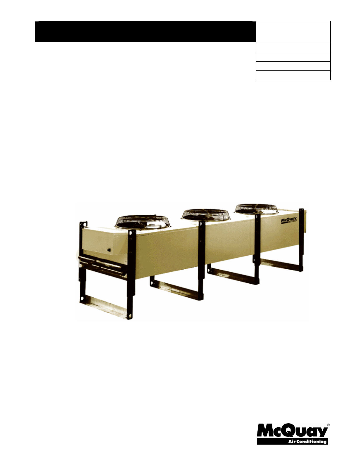
Direct Drive Fluid Coolers
Type AFS 005 Through AFS 107
Type AFD 046 Through AFD 212
Group: Chiller
Part Number: 331375001
Effective: February 2007
Supersedes: January 2005
Page 2
Table of Contents
Product Offering ........................................................................................................3
Introduction................................................................................................................4
Installation ..................................................................................................................4
Unit Location .....................................................................................................................................5
Holding Charge ..................................................................................................................................5
Sound Vibration .................................................................................................................................6
Walls or Obstructions .........................................................................................................................6
Multiple Units ....................................................................................................................................6
Units in Pits........................................................................................................................................6
Decorative Fences ..............................................................................................................................6
General...............................................................................................................................................7
Piping Installation ..............................................................................................................................7
Glycol Charge ....................................................................................................................................9
Mixing Glycol and Water ...................................................................................................................9
Glycol Sludge Prevention...................................................................................................................9
Fluid Circulating Pump ......................................................................................................................9
Physical Data ............................................................................................................10
Dimensional Data .....................................................................................................12
Electrical Data..........................................................................................................14
Electrical Wiring ..............................................................................................................................14
Wiring Diagrams..............................................................................................................................17
Start Up.....................................................................................................................18
Prestart .............................................................................................................................................18
Filling and Purging the System.........................................................................................................18
Temperature Control ........................................................................................................................18
Maintenance .............................................................................................................29
Cleaning Instructions........................................................................................................................29
Manufactured in an ISO certified facility
Illustrations cover the general appearance of McQuay International products at the time of publication and we reserve the right to
make changes in design and construction at anytime without notice.
2 Direct Drive Fluid Coolers IOM AFSD-1
2004 McQuay International
Page 3

AFS
07042A
C
VOLTAGE
CONTROL
ROUGH
OPTION
056
CIRCUIT
Product Offering
MODEL
SIZE
OPTION
OPTION
DUTY
FEED
OPTION
Model
AFS - 1140 RPM fan motors, single-row of fans
AFD - 1140 RPM fan motors, double row of fans
Size
Models 005 through 021 – 1/3 horsepower motors, 1140 RPM fan motors
Models 023 through 212 – 1 ½ horsepower motors, 1140 RPM fan motors
Voltage Option
42 = 208/230 volts / 60 Hertz / 3-phase
27 = 460 volts / 60 Hertz / 3-phase
37 = 575 volts / 60 Hertz / 3-phase
Special – 208 volts / 60 Hertz/ 1-phase, 208/230/380/460 volts/50 Hertz/3-phase
Control Option
A = Fan Cycling Thermostat with Control Transformer (120V)
E = Control Transformer Only (120V)
Y = None
Rough Duty Options
A = Totally enclosed motors
B = Sealtite Wiring
C = PolyGuard fin coating with totally enclosed motors and Sealtite wiring
D = ElectroFin coating with totally enclosed motors and Sealtite wiring
E = PolyGuard Only
F = ElectroFin Only
G = Copper Fins Only (not available on 5 or 6-fan length models)
H = Copper Fins with totally enclosed motors and Sealtite wiring
Circuit Feed Option
Equals the number of feeds (from the header to the first pass of tubes) from capacity tables.
IOM AFSD-1 Direct Drive Fluid Coolers 3
Page 4
Introduction
Carefully check each shipment against the bill of lading and account for all items. Report any shortage
or damage to the delivering carrier. Damaged material is the delivering carrier’s responsibility. Do not
return to the manufacturer without prior approval.
Be careful when uncrating, to prevent damage. Heavy equipment should be left on units shipping base
until it has been moved to the final location. This equipment must be installed in accordance with
accepted industry standards. Failure to meet the following conditions may void the warranty:
1. System piping must be installed following industry standards for good piping practices.
2. Inert gas must be charged into piping during welding.
3. System must be thoroughly leak checked before initial charging.
4. Power supply to system must meet the following conditions:
Voltage for 208/230 motors not less than 195 volts or more than 253 volts.
All other voltages must be within 10% of nameplate ratings.
Phase imbalance not to exceed 2%.
5. All controls and equipment protection circuits properly connected per wiring diagram.
6. Factory installed wiring must not be changed without written factory approval.
7. Relief valves must meet all code requirements.
Installation
Inspection
When the equipment is received, carefully check all items against the bill of lading to check for
a complete shipment. Check all units for damage upon arrival. All shipping damage must be
reported to the carrier and a claim must be filed with the carrier. Check the unit’s serial plate
before unloading the unit to be sure that it agrees with the power supply available. Physical
damage to unit after acceptance is not the responsibility of McQuay International.
Handling
Note: Installation and maintenance are to be performed only by qualified personnel who are
familiar with local codes and regulations, and experienced with this type of equipment.
Avoid rough handling shock due to impact or dropping the unit. Do not push or pull the unit.
Never allow any part of the unit to fall during unloading or moving, as this can result in serious
damage.
Improper lifting or moving unit can result in property damage, severe
personal injury or death. Follow rigging and moving instructions carefully.
DANGER
4 Direct Drive Fluid Coolers IOM AFSD-1
Page 5
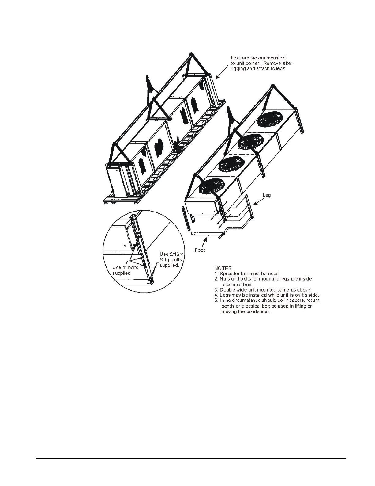
Figure 1, Unit Rigging
Unit Location
Units are designed for outdoor application and may be mounted on a roof or concrete slab
(ground level installation). Install roof mounted units on steel channels or an I-beam frame to
support the unit above the roof. Use of vibration pads or isolators is recommended. The roof
must be strong enough to support the weight of the unit. For ground level installation, mount
units on a one-piece concrete slab with footings extending below the frost line. Be certain
concrete slabs are installed level and are properly supported to prevent settling. Locate the
unit far enough away from any wall or other obstruction to provide sufficient clearance for air
entrance. Do not attach more than two-feet of ductwork to the fan outlet. Avoid air
recirculation conditions that may be caused by sight screening, walls, etc. and keep unit fan
discharge away from any building air intakes. Do not install unit where exhaust or ventilation
equipment will affect entering air temperature or foul coils.
Holding Charge
The unit is shipped with a holding charge of dry nitrogen under nominal pressure.
IOM AFSD-1 Direct Drive Fluid Coolers 5
Page 6
Sound Vibration
AFS = 4 ft.
AFD = 6 ft.
AFS = 4 ft.
AFD = 6 ft.
AFS = 3 ft.
AFD = 4 ft.
Install units away from occupied spaces, utility areas, corridors and auxiliary spaces to
reduce the transmission of sound and vibration to occupied spaces. The fluid piping should
be flexible enough to prevent the transmission of noise and vibration from the unit into the
building. If the fluid lines are to be suspended from the structure of the building, use
isolation hangers to prevent the transmission of vibration. Where piping passes through a
wall, pack fiberglass and sealing compound around the lines to minimize vibration and
retain flexibility. The unit must be secured in its final location. Holes are provided in the
base runner for this purpose
Vertical airflow type units should be located no closer than the width of the unit from a wall
or other obstruction. It two or more units are to be positioned in the same area, a similar
distance should be maintained between adjacent units. Sufficient free area should be left
around and below unit to avoid air restriction to coil.
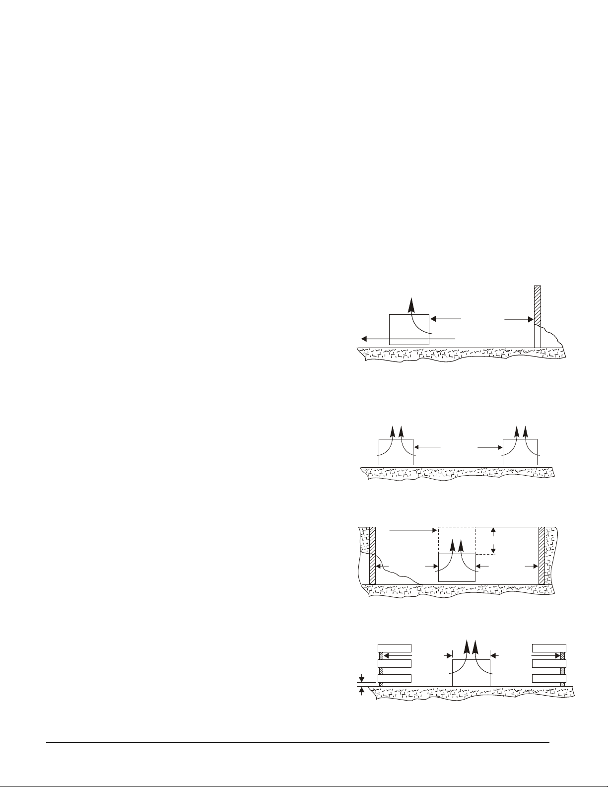
Walls or Obstructions
Locate the unit to ensure that air can
circulate freely and not be recirculated. For
proper air flow and access, all sides of the
unit must be at least the distance shown away
from any wall or obstruction. Increase this
distance whenever possible. Be sure enough
room is left for maintenance through access
doors and panels. Overhead obstructions are
not permitted. When enclosed by three walls
the unit must be installed as indicated for
units in a pit.
AIR FLOW
Multiple Units
For units placed side by side, the minimum
distance between units is as shown. If units
are placed end to end, the minimum distance
between units is 4 feet.
Units in Pits
The top of the unit should not be more than
two feet below the top of the pit, and side
minimum distance on all four sides as
shown.
Decorative Fences
Fences must have 50% free area, with 1 foot
undercut, at least the width of condenser
minimum clearance, and must not be higher
than the top of unit. If these requirements
are not met, unit must be installed as
indicated for "Units in Pits".
AIR FLOW AIR FLOW
AFS = 6 ft.
AFD = 8 ft.
1 IN.
MIN.
STACK
(BY OTHERS
IF SUPPLIED)
AFS = 4 ft.
AFD = 6 ft.
AFS = 3 ft.
AFD = 4 ft.
AIR
FLOW
AIR FLOW
2 FT. MAX.
6 Direct Drive Fluid Coolers IOM AFSD-1
Page 7
General
1. Structure supporting unit must be designed to support both the unit and the fluid.
Table 1 provides weight of fluid per gallon. Provide suitable flashing of the roof, if this
is a roof installation. For ground level mounting, a concrete pad is recommended.
Mounting holes permit the units to be bolted down to withstand wind pressures.
Provide adequate clearance for unobstructed air flow to coils.
2. Level mounting is necessary to ensure proper fluid distribution through the coil as well
as flooded suction for the pump.
Table 1, Fluid Weight Per Gallon at 130
Percent Glycol
0 (Water) 8.25 8.22
10 8.33 8.29
20 8.50 8.37
30 8.58 8.42
40 8.80 8.49
50 8.82 8.53
Pounds per Gallon
Ethylene Glycol
°°°°
F
Pounds per Gallon
Propylene Glycol
3. Water piping must comply with local codes. Correct pipe sizing will help reduce
pumping power and operating costs.
4. In case of doubt, consult the manufacturer for the dry cooler fluid pressure drop at the
specific conditions on your job.
5. Provide sufficient valves and unions to permit easy access to parts subject to wear and
possible repair or replacement.
6. After fluid piping is completed, all joints should be leak tested.
7. Where city water make-up is required, follow local codes, making certain that
disconnecting provisions are provided.
8. Select wire in accordance with nameplate data and local codes.
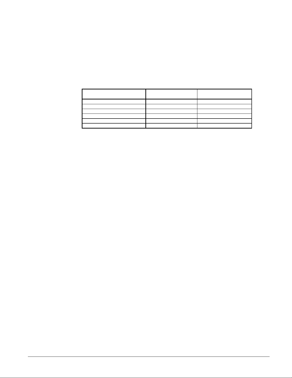
Piping Installation
The piping system should provide maximum leak prevention. Weld or sweat joints should
be used where possible. The fact that glycol solutions or other heat transfer fluids will leak
where water will not, must be taken into account.
The glycol system should not employ an automatic fill with a pressure-reducing valve. This
is because a slight leak would lead to dilution of the mixture and possible freeze potential.
Any refill should be controlled so as to maintain the proper glycol-to-water ratio.
Table 2 shows pressure drops for various pipe sizes at flow rates commonly used with a
typical dry cooler. These pipe sizes are not necessarily always correct for the run from the
condenser to the dry cooler. Proper pipe size will depend on available pump head. This can
be determined by subtracting from the total available pump head at design flow, the
condenser pressure drop and the dry cooler pressure drop. Allow some safety factor for last
minute pipe fittings added to the system and for eventual fouling of the system.
a) Glycol piping requires no insulation except when fluid temperature will be below
ambient dewpoint temperatures.
b) Vents are required at all high points in the piping to bleed air when filling the system.
If fluid coolers are at high points, vent valves should be installed at each fluid cooler.
c) It is recommended that gate valves be installed on both sides of the pump to prevent
loss of fluid in the event the pump should require repair or replacement. Shut-off
valves are also recommended at water cooled condensers in case the condensing unit is
to be moved or requires maintenance involving the coolant system.
IOM AFSD-1 Direct Drive Fluid Coolers 7
Page 8
Table 2, Pressure Loss in Feet of Water
Flow
gpm
15 1 1 1/8 17.6 15.0
20 1 1 1/6 30.2 23.1
25 1 1 1/8 34.6
25 1 1/4 1 3/8 11.5 12.6
30 1 1/4 1 3/8 16.3 17.4
35 1 1/4 1 3/8 21.8 23.0
40 1 3/8 - 26.3
40 1 112 1 5/8 13.0 12.9
45 1 1/2 1 5/8 16.5 15.7
60 - 1 5/8 - 26.3
60 2 2 1/8 7.9 7.0
80 2 2 1/8 13.7 12.0
100 2 1/2 2 5/8 8.5 6.1
150 2 1/2 2 5/8 18.6 12.9
200 3 3 1/8 10.7 9.1
250 3 3 1/8 16.5 13.7
300 3 1/2 3 5/8 11.1 9.2
300 4 4 1/8 5.9 4.9
350 4 4 1/8 7.9 6.5
400 4 1/8 10.2 8.2
Pipe
Size Steel
in.
Type “L”
O.D. Copper
in.
Schedule 40 Steel
Head ft/100 ft
Equiv. Length
Figure 2, Typical Piping
FLUID COOLER
EXPANSION
TANK
VENT AND
FILL VALVE
Copper Tube
Head ft/100 ft.
Equiv. Length
WATER COOLED
CONDENSER
DIVERTING
SHUT-OFF
VALVE
VALVE
CIRCULATING
PUMP
SHUT-OFF
VALVE
REFRIGERATION
COMPRESSOR
EVAPORATOR
WATER CHILLER
TXV
CHILLED WATER
HEAT EXCHANGER
FOR SUPPLEMENTAL
FREE COOLING
NOTE: Isolation valves, vents, drains and other piping specialties are not shown, but are
required for a fully operational system.
8 Direct Drive Fluid Coolers IOM AFSD-1
Page 9
Glycol Charge
The amount of ethylene glycol required depends upon the following:
• The holding volume of the system that includes the holding capacity of the heat source,
the interconnecting piping and the dry cooler.
• Percentage of glycol required by volume to provide protection at the design minimum
operating temperature.
Table 3, Percentage of Glycol to be Added by Percent Volume
Freeze Point °°°°F (°°°°C)
Percent Propylene Glycol
Percent Ethylene Glycol
Use as a guide only. Proper precautions need to be taken to prevent freeze damage during low ambient. Consult
glycol vendor recommendations for specific freeze protection for your location.
30 (-1) 20 (-7) 10 (-12) 0 (-18) -10 (-23) -20 (-29) -30 (-34)
4 16 25 32 38 44 48
5 19 29 36 42 47 51
Mixing Glycol and Water
Regardless of the strength of the mixture, you MUST premix the glycol and water prior to
adding it to the system. The chemical reaction between the two will release oxygen, which
is extremely undesirable in a close-loop system.
CAUTION
For dry coolers operating without a glycol mixture, adequate fluid freeze protection of
some type is necessary during ambient air temperatures below 32°F.
Glycol Sludge Prevention
Glycol systems may be subject to sludge formation in coils, due to one or more of the
following causes:
• Reaction of the corrosion inhibitor with galvanized piping (zinc).
• Reaction of the glycol with chromate type water additives.
• Reaction of the glycol with pipe dope, cutting oils, solder flux, and other system dirt.
Glycol manufacturers offer a specially inhibited glycol (formulated for snow melting
systems) that does not react with zinc. This glycol is also suitable for heat transfer systems.
Glycol manufacturers also provide inhibitor check services on a regular basis.
Consequently, good glycol system design requires the following precautions:
• No galvanized piping is to be used.
• System piping must be thoroughly cleaned and flushed with a heated trisodiurn
phosphate solution before filling with the water/glycol mixture.
• Chromate inhibitor treatment must not be used.
• The glycol manufacturer should provide inhibitor check service and supply additional
inhibitor as required.
Fluid Circulating Pump
Mechanical seal type pumps must be used for glycol systems. Gland type pumps would
cause glycol waste and, if used with a pressure reducing valve, will lead to dilution of the
glycol mixture and eventual freeze-up.
IOM AFSD-1 Direct Drive Fluid Coolers 9
Page 10

Pumps are selected for piping friction loss plus fluid pressure drop through the dry cooler
coil, plus pressure drop through the heat source. No allowance for vertical lift is made
since in a closed system a counterhead acts on the pump suction.
With glycol solutions the pump performance curve will drift to the right from its design
point, due to differences in circuit design, control valve application, pressure drop
calculations, etc. The pump should be selected high on the curve so as to provide for the
"drift'. The pump curve should be "flat" so that the pump will compensate for the inability
to exactly predict the final operating system flow condition and to provide sufficient flow
for satisfactory heat transfer and maximum protection against freezing at the far end of the
circuit. The pump motor should have sufficient power for operating over the entire pump
curve to prevent motor overload at reduced voltages. Paralleled pumps can also be used for
good power economy and continuous and automatic standby operation. Properly applied
parallel pumps will guard against system breakdown caused by a simple pump failure.
Certain older systems have non-operating standby pumps of equal capacity to the operating
unit. We recommend parallel pumps in continuous operation because they provide
practically the same type of standby, in addition to being completely automatic, at lower
initial and operating cost.
Physical Data
The inlet and outlet connection size will be based on the number of feeds in the fluid cooler
circuit. Use the tables below to determine connection sizes.
Table 4, AFS 005 – 021, Connection Sizes
Feeds Inlet / Outlet, in. Feeds Inlet / Outlet, in.
8 1 1/8 24 2 1/8
12 1 3/8 32 2 1/8
16 1 3/8 48 2 5/8
21 1 5/8 64 2 5/8
Table 5, AFS 023 – 107, Connection Sizes (Single-Row of Fans)
Feeds Inlet / Outlet, in.
14 2 1/8
18 2 1/8
21 2 5/8
28 2 5/8
42 3 1/8
56 3 5/8
Table 6, AFD Connection Sizes (Double-Row of Fans, Dual Fluid Connections)
Feeds Inlet / Outlet, in.
18 2 @ 2 1/8
28 2 @ 2 1/8
36 2 @ 2 1/8
42 2 @ 2 5/8
56 2 @ 2 5/8
84 2 @ 3 1/8
112 2 @ 3 5/8
10 Direct Drive Fluid Coolers IOM AFSD-1
Page 11

Table 7, Model 005 through 021, Physical Data
Fan Data
Model
005 1x1 24 180 325 240
008 1x1 26 260 380 330
010 1x2 24 450 600 537
012 1x2 26 470 620 557
014 1x2 26 510 650 615
016 1x2 26 530 680 635
021 1x3 26 550 725 698
Note; Net weight is dry unit only.
Fan
Configuration
Diameter of
Fans
Approx.
Net
Weight, lb.
Approx.
Shipping
Weight, lb.
Approx
Operating
Weight, lb.
Table 8, Model 023 through 212, Physical Data
Model
Configuration
023 1x2 2 23,000 6.7 730 800 788
027 1x2 2 23,200 9.2 790 840 870
031 1x2 2 21,900 9.2 790 860 870
035 1x2 2 20,700 11.8 889 950 992
041 1x3 3 34,800 13.0 1190 1280 1303
045 1x3 3 32,900 13.0 1210 1300 1323
049 1x3 3 31,800 16.7 1240 1330 1385
053 1x4 4 46,400 16.7 1580 1690 1725
061 1x4 4 43,900 16.7 1620 1730 1765
065 1x4 4 42,400 21.7 1650 1760 1839
071 1x4 4 41,500 21.7 1760 1870 1949
075 1x5 5 54,900 20.4 2000 2150 2177
079 1x5 5 54,800 26.6 2020 2150 2251
089 1x5 5 51,800 26.6 2200 2390 2431
097 1x6 6 65,800 31.6 2390 2610 2665
107 1x6 6 62,200 31.6 2630 2850 2905
046 2x2 4 46,000 13.5 1540 1730 1657
054 2x2 4 46,400 18.5 1580 1770 1741
060 2x2 4 43,900 18.5 1620 1820 1781
066 2x2 4 42,400 23.5 1650 1840 1854
070 2x2 4 41,500 23.5 1760 1950 1964
080 2x3 6 69,700 25.9 2360 2570 2585
086 2x3 6 67,000 25.9 2380 2620 2605
090 2x3 6 65,800 25.9 2420 2630 2645
098 2x3 6 63,600 33.4 2480 2690 2771
106 2x4 8 92,900 33.3 3150 3360 3440
120 2x4 8 87,800 33.3 3230 3420 3520
132 2x4 8 84,800 43.3 3300 3470 3677
140 2x4 8 83,000 43.3 3510 3730 3887
152 2x5 10 190,700 40.7 4040 4290 4394
162 2x5 10 109,700 53.1 3990 4270 4452
168 2x5 10 106,000 53.1 4130 4450 4592
178 2x5 10 103,700 53.1 4390 4680 4852
194 2x6 12 131,600 63.1 4790 5150 5339
202 2x6 12 127,200 63.1 4960 5330 5509
212 2x6 12 124,400 63.1 5270 5670 5819
NOTES:
1. All fans are 30 inches in diameter.
2. Net weight is unit only.
3. Operating weight based on 50% ethylene glycol at 130°F.
Fan
Fan Data
Number of
Fans
CFM
AFS Single-Row of Fans
AFD Double Row of Fans
Operating
Charge, gal.
Approx.
Net
Weight, lb.
Approx.
Shipping
Weight, lb.
Approx.
Operating
Weight, lb.
IOM AFSD-1 Direct Drive Fluid Coolers 11
Page 12

Dimensional Data
B
A
B
Figure 3, Dimensions for AFS 005 through AFS 021 with Vertical Flow
21 ½
17
43
34
(3) 7/8 Dia.
8¾
24 ½
Adjustable
16 - 25
Figure 4, Dimensions for AFS 005 through AFS 021 with Horizontal Flow
43
2 ½
37 ½
42 ½
8¾
A
(2) 7/8 Dia.
AFS Model
005 1 39 ¾ 30
008 1 49 ¾ 40
010 2 69 ¾ 60
012 2 69 ¾ 60
014 2 89 ¾ 80
016 2 89 ¾ 80
021 3 129 ¾ 120
Number of
Fans
Dimensions (inches)
A B
NOTES:
1. Inlet is the top connection, outlet the bottom. See
2. The electrical box is on the same end as the fluid connections with knockouts on the bottom and sides.
Table 4
on page 10 for connection sizes.
12 Direct Drive Fluid Coolers IOM AFSD-1
Page 13

NOTES:
1.
Leg extension kits are available to raise unit by 30, 36, or 42 inches.
2.
Inlet is the top connection, outlet the bottom. See
3.
The electrical box is on the same end as the fluid connections with knockouts on the bottom and sides.
4.
Two-fan units, AFD, have two sets of connections and an optional field-installed header.
IOM AFSD-1 Direct Drive Fluid Coolers 13
Table 5
and
Table 6
on page 10 for connection sizes.
Page 14

Electrical Data
Electrical Wiring
The electrical installation should be in accordance with National Electrical Code, local
codes and regulations. Wiring diagrams shown are only basic and do not show fuses,
additional disconnect switches, etc., which must be provided in the field.
Units have a disconnect switch, mounted in the electrical box, with a through-the-door
handle.
All standard motors have internal inherent overload protectors. Therefore, contactors can
be used instead of starters requiring thermal protectors, eliminating the problem of
furnishing the proper heating elements.
All fluid coolers are furnished with either single-phase or three-phase fan motors which, are
identified by the unit data plate.
Electrical leads from each motor terminate at the unit junction box. Field connections must
be made from these leads in accordance with local, state and national codes.
Three-phase motors must be connected to three-phase power of voltage to agree with motor
and unit dataplate.
The motors are wired into a common junction box. The motors must be checked for proper
rotation. Be sure to check that motor voltage and control connection agree with electric
services furnished.
14 Direct Drive Fluid Coolers IOM AFSD-1
Page 15

1140 RPM Motor Data
Table 9, Electrical Data, Model 005 through 021, 1140 RPM
AFS
Model
005 5,050 1 24 1/3 2.6 3.3 6 1.3 1.6 3 1/3 3.4 4.2 6
008 6,450 1 26 1/3 2.6 3.3 6 1.3 1.6 3 1/2 3.9 4.2 6
010 10,100 2 24 1/3 5.2 5.9 10 2.6 2.9 6 1/3 6.8 7.6 10
012 12,400 2 26 1/3 5.2 5.9 10 2.6 2.9 6 1/2 7.8 8.8 10
014 13,700 2 26 1/3 5.2 5.9 10 2.6 2.9 6 1/2 7.8 8.8 10
016 12,900 2 26 1/3 5.2 5.9 10 2.6 2.9 6 1/2 7.8 8.8 10
021 20,500 3 26 1/3 7.8 8.5 10 3.9 4.2 6 1/2 11.7 12.7 15
Notes: 1. Standard motor voltage 208-230-460/3/60.
CFM
Table 10, Electrical Data, Models 023 through 212, 1140 RPM
Model
023 1x2 2 23,000 14.0 15.8 20 7.0 7.9 10 5.6 6.4 10
027 1x2 2 23,200 14.0 15.8 20 7.0 7.9 10 5.6 6.4 10
031 1x2 2 21,900 14.0 15.8 20 7.0 7.9 10 5.6 6.4 10
035 1x2 2 20,700 14.0 15.8 20 7.0 7.9 10 5.6 6.4 10
041 1x3 3 34,800 21.0 22.8 25 10.5 11.4 15 8.4 9.2 10
045 1x3 3 32,900 21.0 22.8 25 10.5 11.4 15 8.4 9.2 10
049 1x3 3 31,800 21.0 22.8 25 10.5 11.4 15 8.4 9.2 10
053 1x4 4 46,400 28.0 29.8 30 14.0 14.9 15 11.2 12.0 15
061 1x4 4 43,900 28.0 29.8 30 14.0 14.9 15 11.2 12.0 15
065 1x4 4 42,400 28.0 29.8 30 14.0 14.9 15 11.2 12.0 15
071 1x4 4 41,500 28.0 29.8 30 14.0 14.9 15 11.2 12.0 15
075 1x5 5 54,900 35.0 36.8 40 17.5 18.4 20 14.0 14.8 15
079 1x5 5 54,800 35.0 36.8 40 17.5 18.4 20 14.0 14.8 15
089 1x5 5 51,800 35.0 36.8 40 17.5 18.4 20 14.0 14.8 15
097 1x6 6 65,800 42.0 43.8 50 21.0 21.9 25 16.8 17.6 20
107 1x6 6 62,200 42.0 43.8 50 21.0 21.9 25 16.8 17.6 20
046 2x2 4 46,000 28.0 29.8 30 14.0 14.9 15 11.2 12.0 15
054 2x2 4 46,400 28.0 29.8 30 14.0 14.9 15 11.2 12.0 15
060 2x2 4 43,900 28.0 29.8 30 14.0 14.9 15 11.2 12.0 15
066 2x2 4 42,400 28.0 29.8 30 14.0 14.9 15 11.2 12.0 15
070 2x2 4 41,500 28.0 29.8 30 14.0 14.9 15 11.2 12.0 15
080 2x3 6 69,700 42.0 43.8 50 21.0 21.9 25 16.8 17.6 20
086 2x3 6 67,000 42.0 43.8 50 21.0 21.9 25 16.8 17.6 20
090 2x3 6 65,800 42.0 43.8 50 21.0 21.9 25 16.8 17.6 20
098 2x3 6 63,600 42.0 43.8 50 21.0 21.9 25 16.8 17.6 20
106 2x4 8 92,900 56.0 57.8 60 28.0 28.9 30 22.4 23.2 30
120 2x4 8 87,800 56.0 57.8 60 28.0 28.9 30 22.4 23.2 30
132 2x4 8 84,800 56.0 57.8 60 28.0 28.9 30 22.4 23.2 30
140 2x4 8 83,000 56.0 57.8 60 28.0 28.9 30 22.4 23.2 30
152 2x5 10 190,700 70.0 71.8 80 35.0 35.9 40 28.0 28.8 30
162 2x5 10 109,700 70.0 71.8 80 35.0 35.9 40 28.0 28.8 30
168 2x5 10 106,000 70.0 71.8 80 35.0 35.9 40 28.0 28.8 30
178 2x5 10 103,700 70.0 71.8 80 35.0 35.9 40 28.0 28.8 30
194 2x6 12 131,600 84.0 85.8 90 42.0 42.9 45 33.6 34.4 40
202 2x6 12 127,200 84.0 85.8 90 42.0 42.9 45 33.6 34.4 40
212 2x6 12 124,400 84.0 85.8 90 42.0 42.9 45 33.6 34.4 40
1. All fan blades are 30” in diameter.
2. Standard motors are 1 ½ HP, 208-230/460/3/60 or 575 volt.
1. Optional single-phase motors are ¾ hp, 208/230 volt, 4.8 FLA, 1140 rpm.
Fan Data 208-230/3/60 460/3/60 575/3/60
Fan
Config.
Fans 208-230/3/60 460/3/60 208-230/1/60
No.
No. of
Fans
Dia.
in.
HP
cfm
Total
FLA
MCA
Total
FLA
AFS Single-row of Fans
AFD Double Row of Fans
MCA
Max
Fuse
Max.
Fuse
Total
FLA
Total
FLA
MCA
MCA
Max
Fuse
Max.
Fuse
HP
Total
FLA
Total
FLA
MCA
MCA
Max
Fuse
Max.
Fuse
IOM AFSD-1 Direct Drive Fluid Coolers 15
Page 16

830 RPM Motor Data
Table 11, Electrical Data, Models 023 through 212, 830 RPM
Model
023 1x2 2 9.6 10.8 15 4.8 5.4 6 4.0 4.5 10
027 1x2 2 9.6 10.8 15 4.8 5.4 6 4.0 4.5 10
031 1x2 2 9.6 10.8 15 4.8 5.4 6 4.0 4.5 10
035 1x2 2 9.6 10.8 15 4.8 5.4 6 4.0 4.5 10
041 1x3 3 14.4 15.6 20 7.2 7.8 10 6.0 6.5 10
045 1x3 3 14.4 15.6 20 7.2 7.8 10 6.0 6.5 10
049 1x3 3 14.4 15.6 20 7.2 7.8 10 6.0 6.5 10
053 1x4 4 19.2 20.4 25 9.6 10.2 15 8.0 8.5 10
061 1x4 4 19.2 20.4 25 9.6 10.2 15 8.0 8.5 10
065 1x4 4 19.2 20.4 25 9.6 10.2 15 8.0 8.5 10
071 1x4 4 19.2 20.4 25 9.6 10.2 15 8.0 8.5 10
075 1x5 5 24.0 25.2 30 12.0 12.6 15 10.0 10.5 15
079 1x5 5 24.0 25.2 30 12.0 12.6 15 10.0 10.5 15
089 1x5 5 24.0 25.2 30 12.0 12.6 15 10.0 10.5 15
097 1x6 6 28.8 30.0 30 14.4 15.0 15 12.0 12.5 15
107 1x6 6 28.8 30.0 30 14.4 15.0 15 12.0 12.5 15
046 2x2 4 19.2 20.4 25 9.6 10.2 15 8.0 8.5 10
054 2x2 4 19.2 20.4 25 9.6 10.2 15 8.0 8.5 10
060 2x2 4 19.2 20.4 25 9.6 10.2 15 8.0 8.5 10
066 2x2 4 19.2 20.4 25 9.6 10.2 15 8.0 8.5 10
070 2x2 4 19.2 20.4 25 9.6 10.2 15 8.0 8.5 10
080 2x3 6 28.8 30.0 30 14.4 15.0 15 12.0 12.5 15
086 2x3 6 28.8 30.0 30 14.4 15.0 15 12.0 12.5 15
090 2x3 6 28.8 30.0 30 14.4 15.0 15 12.0 12.5 15
098 2x3 6 28.8 30.0 30 14.4 15.0 15 12.0 12.5 15
106 2x4 8 38.4 39.6 40 19.2 19.8 20 16.0 16.5 20
120 2x4 8 38.4 39.6 40 19.2 19.8 20 16.0 16.5 20
132 2x4 8 38.4 39.6 40 19.2 19.8 20 16.0 16.5 20
140 2x4 8 38.4 39.6 40 19.2 19.8 20 16.0 16.5 20
152 2x5 10 48.0 49.2 50 24.0 24.6 25 20.0 20.5 25
162 2x5 10 48.0 49.2 50 24.0 24.6 25 20.0 20.5 25
168 2x5 10 48.0 49.2 50 24.0 24.6 25 20.0 20.5 25
178 2x5 10 48.0 49.2 50 24.0 24.6 25 20.0 20.5 25
194 2x6 12 57.6 58.8 60 28.8 29.4 30 24.0 24.5 30
202 2x6 12 57.6 58.8 60 28.8 29.4 30 24.0 24.5 30
212 2x6 12 57.6 58.8 60 28.8 29.4 30 24.0 24.5 30
Notes:
1. All fan blades are 30” in diameter.
2. All motors are 1 HP, 208-230/460/3/60 or 575 volt.
Fan Data 208-230/3/60 460/3/60 575/3/60
Fan
Config.
No. of
Fans
Total
FLA
MCA
AFD Double Row of Fans
Max.
Fuse
AFS Single-row of Fans
Total
FLA
MCA
Max.
Fuse
Total
FLA
MCA
Max.
Fuse
16 Direct Drive Fluid Coolers IOM AFSD-1
Page 17
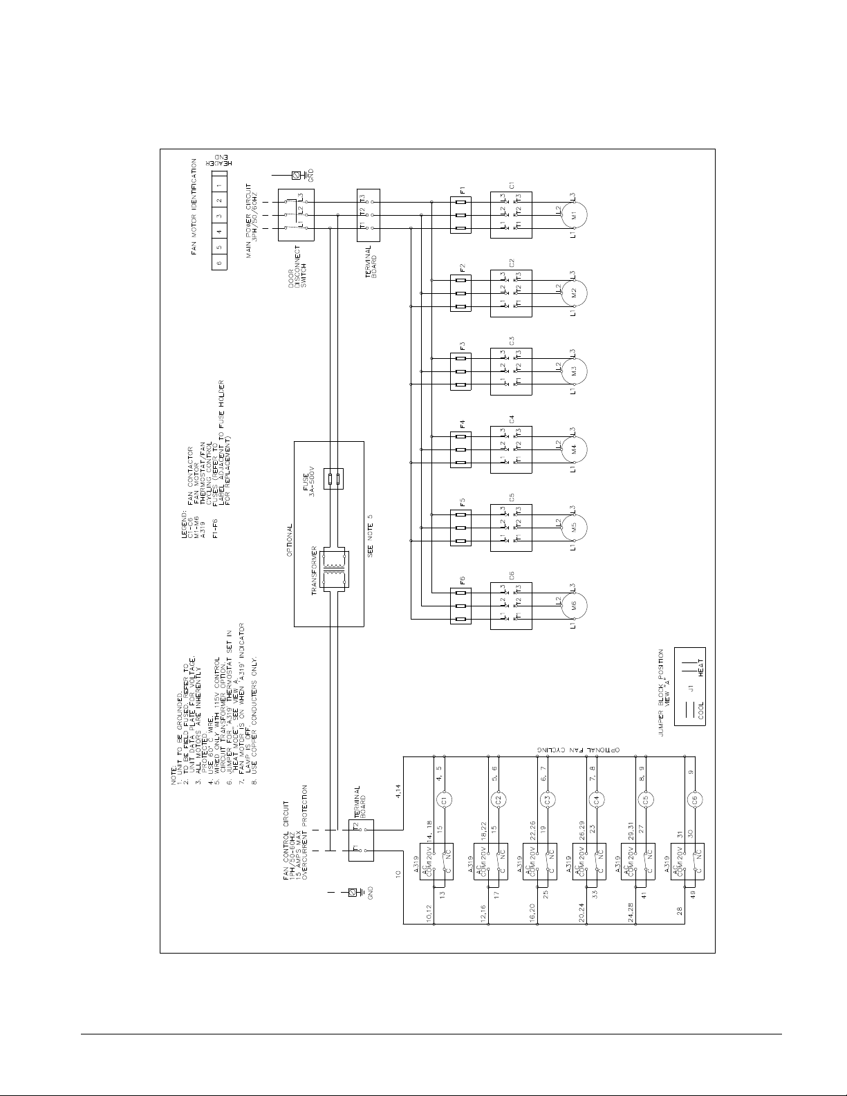
Wiring Diagrams
Figure 5, Typical Wiring for AFS Models
NOTE: Unit specific wiring diagrams are shipped with the unit.
IOM AFSD-1 Direct Drive Fluid Coolers 17
Page 18

Start Up
Prestart
Check for correct dry cooler fan rotation. This can be done by quickly jogging the fan
contactor. Be sure that the fans run freely. The same check is recommended for pumps.
Filling and Purging the System
The system should be pressure tested before adding glycol. The system can be tested with
air or water, however if the ambient temperature is at or below freezing the use of air is
recommended. Test pressure should not exceed 60 psig.
Roof Mounted Fluid Cooler
To fill the system, pour the premixed water and glycol into the expansion tank. Fill the
system until the expansion tank is half full, then purge the air from all vents. Operate the
system for a minute, then purge all vents again, and add glycol as required. Repeat the
purging of vents after the first hour of operation and again after several hours of operation.
Ground Mounted Fluid Cooler
The fluid cooler may be lowest point in the system; consequently the premixed water and
glycol will have to be pumped into the system.
Temperature Control
General
Some method of controlling the fluid temperature is required.
The standard temperature control consists of fan contactors arranged for field-connection to
a field-supplied and mounted control system; in other words, no control. Setting and
adjusting these controls will depend on the type furnished.
McQuay can furnish an optional control system using Johnson Controls A419 temperature
controls. Installation and adjustment are explained in the following paragraphs.
Installation
If the fan cycle thermostat option is provided, the solid state sensors are shipped coiled in
the control panel to prevent damages during shipment and installation. Mounted the sensors
securely to the fluid cooler header and insulate. Mount sensors on the entering or leaving
fluid headers depending on site requirements. Route and secure sensor wiring for
protection from vibration and interference.
Setting
The control is a single-stage, electronic temperature control with an SPDT output relay. It
has the following features:
• lockable keypad for programming,
• LCD for temperature and status display,
• LED for output relay status
• heating and cooling modes with adjustable setpoint and differential
18 Direct Drive Fluid Coolers IOM AFSD-1
Page 19

The electronic temperature control must be set for heating or cooling application by
placement of the mode jumper. Temperature setting is selected based on entering or leaving
fluid temperature control. Differential settings are selected to prevent excessive fan cycling
and fluid temperature swing.
Definitions
• Cut-in: The temperature at which the N.O. (Normally Open) SPDT (Single-Pole,
Double-Throw) output relay contact closes.
• Cut-out: The temperature at which the N.O. SPDT output relay contact opens.
Control Functions
The A419 control allows the user to set a variety of functions using the keypad and
jumpers. These functions are described below. For instructions on setting function
parameters, see the Adjustments section.
Keypad Programmable Functions
Setpoint (SP) establishes the temperature at which the equipment is switched on or off,
depending on the user selected mode of operation. Setpoint range is -30 to 212°F (-34 to
100°C). See the Cooling/Heating and Setpoint Modes section on page 21.
If Setpoint mode is set to Cut-in, the setpoint is the temperature at which the control closes
the N.O. contacts. If Setpoint mode is set to Cut-out, the setpoint is the temperature at
which the N.O. contacts open. Refer to Figure 8 and Figure 9.
Differential (dIF) establishes the difference in temperature between Cut-in and Cut-out.
The differential is set relative to Setpoint and may be set from 1 to 30F° or C. Refer to
Figure 8 and Figure 9.
Anti-Short Cycle Delay (ASd) establishes the minimum time that the fan remains off
before restarting again. The anti-short cycle delay is activated when the A419 control has
cycled the fan off. The delay does not allow the fan to be restarted until the programmed
amount of time has elapsed. When the delay is activated, the LCD alternately flashes the
sensor temperature and ASd. The anti-short cycle delay may be programmed for 0 to 12
minutes in 1-minute increments.
For example, if the anti-short cycle delay is programmed for 7 minutes, the control will not
restart the fan until 7 minutes after the equipment was turned off, regardless of the
temperature. During the 7-minute period, if the temperature reaches the cut-in setpoint, the
display alternates between the sensor temperature and ASd to indicate that the on cycle is
being delayed. After the 7-minute delay has elapsed, the fan is turned on, and ASd stops
flashing.
Note: A power interruption to the control will activate the anti-short cycle delay.
Figure 6, Anti-short Cycle Delay
IOM AFSD-1 Direct Drive Fluid Coolers 19
Page 20

Sensor Failure Operation (SF): establishes how the A419 control operates the fan in the
event of a sensor or sensor wiring failure. The user may select either to run the equipment
continuously or to shut it down. When the control detects a sensor circuit failure, the LCD
flashes SF alternately with OP if the sensor circuit is open, or SH if the sensor circuit is
shorted. Before indicating a failure, the control implements a 1-minute delay, which allows
verification of failure condition and avoids nuisance failure indications.
Temperature Offset (OFS): establishes the temperature setpoint shift (F° or C°) applied
when the binary input (BIN) and common (COM) terminals are connected together. The
Temperature Offset may be set from 0 to 50F° or C°. See the Offset Function section on
page 20.
Temperature Units: establishes the units of temperature (Fahrenheit or Celsius) displayed
on the LCD.
Functions Set by Jumper Position
For instructions on positioning jumpers, see Positioning the Jumpers on page 22 in the
Adjustments section. Refer to Figure 11 for jumper locations.
Heating/Cooling: Removing or installing the upper jumper at P4 establishes whether the
control operates in the Heating or Cooling mode.
Setpoint Mode: Removing or installing the lower jumper at P4 establishes whether
Setpoint is the Cut-in temperature or Cut-out temperature.
Keypad Lock: Removing or installing the jumper at P5 establishes whether the keypad is
locked or unlocked. Locking the keypad deters accidental or unauthorized changes to all of
the function parameters.
Temperature Offset Function
The Temperature Offset function shifts Heating setpoint lower and Cooling setpoint higher
by the value
applications.
The Temperature Offset is activated by closing a circuit between BIN and COM. (See
Figures 7, 8, or 9.) The BIN and COM terminals may be connected to a user-supplied
external switching device, such as a time clock, that has a set of SPST contacts.
This option enables the control to alternate between two temperature setpoints based on the
position of the binary input switch. The number of degrees added to, or subtracted from,
Setpoint is established in the Temperature Offset function (OFS) using the keypad, as
described in Setting Other Functions on page 25.
Table 12 shows an example of the effect of the Temperature Offset function when
active.
Table 12, Sample Offset Function Effect
Mode Setpoint
Cooling
Heating
*Setpoint when switch is closed.
in
the Temperature Offset. This function is not normally used on fluid cooler
Temperature
Offset Value
70° 8° 78°
70° 8° 62°
Shifted
Setpoint*
it
is
When the binary input (BIN) is connected to the common (COM), the Offset function is
enabled and BIN is displayed on the LCD above the °F or °C symbol, as shown in Figure 4.
20 Direct Drive Fluid Coolers IOM AFSD-1
Page 21

Display
The front panel of the A419 control has a liquid crystal display (LCD) and an output relay
status LED (Light-Emitting Diode) indicator.
Liquid Crystal Display
During normal operation, the LCD displays the sensor temperature, a symbol indicating
units of temperature (°F or °C), and an icon indicating Heating ( ) or Cooling (∗) mode.
See Figure 7.
The temperature value ranges from -30 to 212°F (-34 to 100°C) in 1° increments. The LCD
also displays BIN if the Temperature Offset function is activated.
Figure 7, Front Panel and Display
During programming, the LCD
displays the control functions and
their programmed values. After
30 seconds of inactivity, the
display returns to the sensor
temperature. See the Adjustments
section for instructions on using
the keypad to change settings.
Output Relay Status Indicator LED
A green LED on the control’s front panel illuminates when the output relay is energized and
the N.O. contacts are closed.
Cooling/Heating and Setpoint Modes
Jumpers are used to place the A419 control in Cooling or Heating mode and set whether
Cut-in or Cut-out occurs at Setpoint. Four operating modes are possible: Cooling/Cut-in,
Cooling/Cut-out, Heating/Cut-in, and Heating/Cut-out.
Cooling Modes
When Cooling/Cut-in mode is selected, the differential is below Setpoint. The output relay
energizes and the LED indicator illuminates when the temperature rises to Setpoint. When
the temperature drops to Setpoint minus the differential value, the output relay and LED
indicator de-energize.
When Cooling/Cut-out mode is selected, the differential is above Setpoint. The output
relay energizes and LED indicator illuminates when the temperature rises to Setpoint plus
the differential value. When the temperature drops to Setpoint, the output relay and LED
indicator de-energize.
IOM AFSD-1 Direct Drive Fluid Coolers 21
Page 22

Figure 8, Cooling Modes
Heating Modes
When the Heating/Cut-in mode is selected, the differential is above Setpoint. The output
relay energizes and LED indicator illuminates when the temperature drops to Setpoint.
When the temperature rises to Setpoint plus the differential value, the output relay and LED
de-energize.
When Heating/Cut-out mode is selected, the differential is below Setpoint. The output
relay energizes and LED indicator illuminates when the temperature drops to Setpoint
minus the differential value. When the temperature rises to Setpoint, the output relay and
LED indicator de-energize.
Figure 9, Heating Modes
Adjustments
This section provides instructions for adjusting the A419 control using the jumpers and
keypad.
IMPORTANT: Verify that the Cooling/Heating jumper is positioned properly before
powering the A419 control, so that the relay operates as intended.
Positioning the Jumpers
The P5 Jumper Pin Block has a single set of jumper pins and is used to lock or unlock the
keypad. The P4 Jumper Pin Block has two sets of jumper pins.
22 Direct Drive Fluid Coolers IOM AFSD-1
Page 23

The top set of pins at P4, labeled JUMPI, is used to set the control for Heating or Cooling
mode. The bottom set of pins, labeled JUMP2, is used to establish Setpoint at cut-in or at
cut-out. See Figure 11.
Figure 10, Positioning the Jumpers
To position a jumper in the
Installed position, place the
jumper on both pins. To position
a jumper in the Removed position,
place the jumper on only one pin.
(Saving the jumper in case it is
required in the future.) See
Figure 10.
Set the jumpers as follows, using Figure 10 and Figure 11 as guides.
1. Verify that all power to the A419 control has been removed.
2. Remove the control’s cover by loosening the four captive cover screws.
3. Position the jumpers to set Cooling/Heating, Setpoint, and Keypad Lock functions.
4. Replace the cover and fasten in place with the four screws.
5. Restore power to the control.
Figure 11, Jumper Positions and Control Settings
IOM AFSD-1 Direct Drive Fluid Coolers 23
Page 24

Table 13, Jumper Designations, Positions, and Control Settings
Function
Operating Mode
Cooling/Heating
Setpoint
Keypad Lock P5-Keypad Unlock
Jumper Pins Designation
on Control
JUMP1
(Top Pair of Pins on Block
P4)
JUMP2
(Bottom Pair of Pins on
Block P4)
Setting
Cooling Removed
Heating Installed
At Cut-in Removed
At Cut-out Installed
Locked Removed
Unlocked Installed
*IMPORTANT: The keypad cannot be unlocked without a jumper. Do not discard any
jumpers in case they are required in the future. To position a jumper in the Removed
position, place the jumper on only one pin. (Saving the jumper in case it is required in the
future.)
Jumper
Position*
Factory Default Setting
(and Jumper Position)
Cooling
(Removed position)
Cut-in
(Removed Position)
Unlocked
(Installed Position)
Changing Temperature Units
The A419 control is set at the factory to display in Fahrenheit temperature units.
To convert to Celsius units, press the Up and Down buttons
simultaneously. Press them again to return to Fahrenheit units.
Note: Make sure the Keypad Lock jumper is in the unlocked (installed) position before
adjusting the control. Verify that the control is displaying the desired temperature units
before setting the setpoint.
Setting the Setpoint
To view and adjust the setpoint, follow these steps:
1. Press and hold the Menu button until the display changes to flashing
SP. This will take about 2 seconds.
Note: If no entries are made for 30 seconds, the control reverts to the temperature display.
2. Press the Menu button again. The current setpoint is displayed.
3. Press the Up or Down button to adjust the setpoint temperature.
4. Press the Menu button to save. The display then returns to the sensor
temperature
.
Note: If the Menu button is not pressed after changing the setpoint, the control reverts to
the setpoint value previously programmed into the A419 control.
24 Direct Drive Fluid Coolers IOM AFSD-1
Page 25

Table 14, Function Ranges and Settings
Function Range
SP: Setpoint
dIF: Differential
ASd: Anti-short Cycle_Delay
OFS: Temperature Offset
SF: Sensor Failure
Operation
-30to212°F
(-34 to 100°C)
I to 30° (F or C) 5
0 to 12 minutes I
0 to 50° (F or C) 0
0 = output de-energized
1 = output energized
Factory
Setting
30
1
NOTES:
Operation at Extremes: If the combination of setpoint, plus or minus the differential, falls
outside the temperature range (-30 to 212°F), the A419 control operates as follows:
Cooling/Cut-in: If the control is operating in Cooling/Cut-in mode and setpoint minus
differential is less than -30°F, the control switches on at setpoint and off when the
temperature drops below -30°F (-34°C).
Heating/Cut-in: If the control is operating in Heating/Cut-in mode and setpoint plus
differential is greater than 212°F (100°C), the control switches on at setpoint and off when
the temperature exceeds 212°F (100°C).
Cooling/Cut-out: If the control is operating in Cooling/Cut-out mode and setpoint plus
differential is greater than 2 12°F (100°C), the control switches on when the temperature
exceeds 212°F (100°C) and off at setpoint.
Heating/Cut-out: If the control is operating in Heating/Cut-out mode and setpoint minus
differential is less than -30°F (-34°C), the control switches on when the temperature drops
below -30°F (-34°C) and off at setpoint.
Setting Other Functions
To set the Differential (dIF), Anti-short Cycle Delay (ASd), Temperature Offset (OFS), or
Sensor Failure (SF) operation, use the following method.
Figure 12, Order of the Functions
Figure 12 illustrates the order of functions shown
using the Up or Down button. The Up button
accesses functions in the clockwise direction; the
Down button accesses functions in the
counterclockwise direction.
IOM AFSD-1 Direct Drive Fluid Coolers 25
Page 26

1.
Press and hold the Menu button until the display changes to
flashing SP. This will take about 2 seconds
.
Note: If no entries are made for 30 seconds while programming is in progress, the control
reverts to the temperature display.
2.
Press the Up or Down button repeatedly until the desired function
is displayed
.
3. Press the Menu button to display the function’s current value.
4. Press the Up or Down button until the desired value is displayed.
5. Press the Menu button to save the new value. The display then
returns to the sensor temperature.
Note: If you do not press the Menu button after setting the new value, the
control reverts to the previously programmed value for that function
.
Checkout
Before applying power, make sure installation and wiring connections are according to job
specifications. After necessary adjustments and electrical connections have been made, put
the system in operation and observe the control for at least three complete operating cycles
before leaving the installation.
Troubleshooting
If the control system does not function properly, verify that the unit is wired, configured,
and set properly. If the problem persists, use the following procedures to determine the
cause of the problem:
1. Check for proper supply voltage to the A419 control.
a) Remove the cover by loosening the four captive cover screws.
WARNING
Risk of Electrical Shock. High voltages may be present at electrical terminals
and other exposed internal metal surfaces. Avoid contact with all metal
surfaces on control when cover is removed.
26 Direct Drive Fluid Coolers IOM AFSD-1
:
Page 27

b) Use a reliable AC voltmeter to check the voltage between the COM and I20V or
240V terminals on line voltage models and the two 24V terminals on low-voltage
models. Refer to the wiring diagrams furnished with the unit.
c)
The voltage must be between 20 and 30 VAC for 24 volt applications, 102 and 132
VAC for 120 volt applications, 177 and 264 VAC for 208/240 volt applications
If the voltage reading is within the required range, proceed to Step 2.
If the voltage reading is not within the required range, check the power source and
input power wires for problems.
2. Check for proper sensor operation.
a. Disconnect all power sources to control.
b. Take a temperature reading at the sensor location, using an accurate thermometer.
c. Disconnect the sensor from the control.
d. Using an ohmmeter, measure the resistance across the two sensor leads while the
sensor is at the temperature taken in step b.
e. Consult
to established temperature and resistance values.
f. If the measured values conform to the values in
g. If the sensor’s measured resistance value is substantially different from the
expected value for that temperature, check the sensor wiring. If sensor wiring is
OK, replace the sensor.
Figure 13, Nominal Temperature vs. Sensor Resistance
Figure 13
to verify that the measured temperature and resistance conform
Figure 13
, proceed to Step 3.
Check the A419 for proper operation.
Note: Perform Troubleshooting Steps 1 and 2 before performing this step.
a. Disconnect the load from the output relay terminals.
b. Check that the Keypad Lock jumper is installed, so that the keypad is unlocked.
c. Reconnect the sensor leads and supply power to the control.
d. Replace the cover.
e. Check the control settings for proper values.
IOM AFSD-1 Direct Drive Fluid Coolers 27
Page 28

f. Press and hold the Menu button until Setpoint appears (occurs in about 2 seconds).
g. Use the Up and Down buttons to change the Setpoint temperature above and below
the current sensor temperature until the output relay energizes and de-energizes as
shown in
Table 15
.
Note: If the anti-short cycle delay has a time greater than 0 minutes, the relay will
not energize until the timed delay has elapsed.
h. If the output relay does not perform as indicated in
Table 15
, replace the A419
control.
i. If proper operation of the A419 control is verified, reconnect the load and consult
the equipment manufacturer’s instructions for troubleshooting the controlled
equipment.
Table 15, A419 Output Relay Operation
Setpoint
Mode
Cut-out
Cut-in
Operating
Mode
Cooling Setpoint plus differential Setpoint
Heating Setpoint minus differential Setpoint
Cooling Setpoint
Heating Setpoint
Output Relay Energized at... Output Relay De-energized at...
Setpoint minus
differential
Setpoint plus
differential
Note: When the relay is energized, the N.O. contacts are closed and the LED is illuminated.
Fault Codes
If the LCD displays an alarm or fault code (SF or EE), consult Table 6 for explanation.
Table 6, Fault Codes Defined
Fault Code Definition System Status Solution
SF flashing
alternately
with Op
SF flashing
alternately
with SH
EE
Open temperature
sensor or sensor
wiring
Shorted
temperature
sensor or sensor
wiring
Program failure Output is off Reset the control by
Output functions
according to the selected
sensor failure mode (SF
setting)
Output functions
according to the selected
sensor failure mode (SF
setting)
See Troubleshooting
section. Cycle power to
reset the control.
See Troubleshooting
section. Cycle power to
reset the control.
pressing the Menu button.
If problems persist,
replace the control.
28 Direct Drive Fluid Coolers IOM AFSD-1
Page 29

Maintenance
Fluid coolers require a minimum of maintenance. Electrical connections should be checked
on an annual basis. Fan contactors should be inspected and replaced when there is evidence
of pitting or burning. Verify controls settings and operation at least on an annual basis.
Condenser fan motors have sealed ball bearings that do not require service. Replace
bearings when necessary.
The cooling fluid should be checked on a regular basis for proper inhibitors and glycol mix.
The unit coil will require periodic cleaning based on operation and atmosphere conditions.
Clean the unit using a brush or commercially available coil cleaners and water. Take care
not to deform the fin material. Straighten any bent fins using a fin tool.
Cleaning Instructions
Clean the finned surface at least every six months; more frequent cleaning may be required
if extreme conditions cause clogging or fouling of air passages through the finned surface.
Use Calgon Corporation's CalClean 41352 (or equal). Apply CalClean liberally to entering
air and leaving air surfaces of the finned area according to label directions and rinse
thoroughly to remove all cleaners.
CAUTION
Never clean this unit with an acid based cleaner.
IOM AFSD-1 Direct Drive Fluid Coolers 29
Page 30

This document contains the most current product information as of this printing. For the most up-todate product information, please go to www.mcquay.com.
Post Office Box 2510 Staunton, Virginia 24402-2510 USA • 540.248.0711 • www.mcquay.com IOM AFSD-1 (2/07)
 Loading...