

Page 1
AAF®-HermanNelson® Self-Contained Air
Source Heat Pump Unit Ventilator
Model AEQ Size 024 (2 Ton) to 054 (4.5 Ton)
R-410A Refrigerant, MicroTech II™ (“F” V intage)
Catalog UV1650
C
Page 2

Contents
Introduction
Nomenclature ...............................................................................3
AAF-HermanNelson Self-Contained Air Source Heat Pump
Classroom Unit Ventilator .............................................................4
Model AEQ Air Source Heat Pump Self-Contained Unit Ventilato
.....................................................................................................5
Features & Benets
GentleFlo Delivery ........................................................................6
The Right Amount of Fresh Air and Cooling .................................7
Precise Temperature and Dehumidication Control .....................7
Low Installation Costs ..................................................................8
Low Operating Costs ....................................................................9
Easy To Maintain ........................................................................10
Built To Last ................................................................................12
MicroTech II Controls
MicroTech II Controls For Superior Performance,
Easy Integration ................................................................... 13-18
MicroTech II Sensors & Control Component Locations ........ 19-21
Accessories
Time Clock ..................................................................................22
ServiceTools ...............................................................................22
Wall Louvers & Grilles ................................................................23
VentiMatic Shutter Room Exhaust Ventilation ...................... 24-25
Storage Cabinets, Sink & Bubbler ........................................ 26-27
End Panels .................................................................................27
Unit Selection
Quick Selection Procedure ................................................... 40-43
Selection Procedure ...................................................................44
Engineering Data .................................................................. 45-46
Electrical Data - Size 024 and 036 .............................................45
Electrical Data - Size 044 and 054 .............................................46
General Unit Data - Model AEQ .................................................46
Details & Dimensions
Unit Size 024 ..............................................................................47
Unit Size 036 ..............................................................................48
Unit Sizes 044 & 054 ..................................................................49
End Panels .................................................................................50
Wall Intake Louvers & Grilles .....................................................51
VentiMatic Shutter Assembly ......................................................52
Sink & Bubbler Cabinet ..............................................................53
Utility Compartment & Filler Sections ........................................54
Wiring Diagrams
MicroTech II Wiring - Typical.......................................................55
Typical Wall Senors ....................................................................56
External Input Wiring ..................................................................56
External Output Wiring-Single Unit .............................................57
External Output Wiring-Multiple Units ........................................57
Guide Specications
AAF-HermanNelson Self-Contained Air Source Heat Pump Unit
Ventilator Model AEQ Guide Specications ......................... 58-61
Applications Considerations
Why Classrooms Overheat .................................................. 28-31
Meeting IBC Seismic Requirements ...........................................32
ASHRAE Cycle II ........................................................................33
Unit Installation Considerations ............................................ 34-36
Wall Sleeve Arrangements ................................................... 37-39
C
McQuay is a registered trademark and MicroTech II, Digital Ready, GentleFlo, ServiceTools,
Microsoft is a registered trademark and Windows is a trademark of Microsoft Corporation.
and Protocol Selectability are trademarks of McQuay International.
Copyright © 2010 McQuay International. All rights reserved throughout the world.
Page 3
Introduction
Nomenclature
U AEQ 6 024 C G 12 Z B1 AL 22 G B B 1
Unit Type
U = Unit Ventilator
Product Identier
AEQ = SC - a/c Air Source
Heat Pump, Ultra Quiet
Design Series
6 = F Design
Nominal Capacity, cubic
feet/minute (cfm)
024 = 24,000 Btuh
036 = 36000 Btuh (Replacement Only)
044 = 44,000 Btuh (Replacement Only)
054 = 54,000 Btuh (Replacement Only)
Voltage
C = 208-60-1
D = 208-60-3
G = 230-60-1
H = 230-60-3
K = 460-60-3
Cooling Options
G = Direct Expansion (DX)
H = Direct Expansion (DX) with refrigerant relief valve
Heating Options
12 = Low Electric Heat, 3-Element
13 = High Electric Heat, 6-Element
Hand Orientation [Right (RH) Left (LH)]
Z = Not applicable
Controls (TC = Time Clock, CO2 = CO2 Sensor)
B1 = Basic Stand-Alone w/o TC
B2 = Basic Stand-Alone Master w/o TC
B3 = Basic Stand-Alone Slave w/o TC
B4 = Basic BACnet MS/TP w/o TC
B5 = Basic LonMark SCC w/o TC
B6 = Basic Metasys N2 Open w/o TC
B7 = Basic Stand-Alone w/ TC
B8 = Basic Stand-Alone Master w/ TC
B9 = Basic Stand-Alone w/o TC w/CO2
BA = Basic Stand-Alone Master w/o TC w/CO2
BB = Basic Stand-Alone Slave w/o TC w/CO2
BC = Basic BACnet MS/TP w/o TC w/CO2
BD = Basic LonMark SCC w/o TC w/CO2
BE = Basic Metasys N2 Open w/o TC w/CO2
BF = Basic Stand-Alone w/ TC w/CO2
BG = Basic Stand-Alone Master w/ TC w/CO2
E1 = Expanded Stand-Alone w/o TC
E2 = Expanded Stand-Alone Master w/o TC
E3 = Expanded Stand-Alone Slave w/o TC
E4 = Expanded BACnet MS/TP w/o TC
E5 = Expanded LonMark SCC w/o TC
E6 = Expanded Metasys N2 Open w/o TC
E7 = Expanded Stand-Alone w/ TC
E8 = Expanded Stand-Alone Master w/ TC
Product Styles
1 = Product Style 1
Warranty
A = Standard
E = Extended
X = Special
SKU
B = Standard Delivery
C = Ext. Delivery
Power Connection
G = Box w/Switch
Return Air
22 = RA Bottom Front / OA Rear Duct Collar
Discharge
AL = 16-5/8" Unit, Top Bar Grille Discharge
E9 = Expanded Stand-Alone w/o TC w/CO2
EA = Expanded Stand-Alone Master w/o TC w/CO2
EB = Expanded Stand-Alone Slave w/o TC w/CO2
EC = Expanded BACnet MS/TP w/o TC w/CO2
ED = Expanded LonMark SCC w/o TC w/CO2
EE = Expanded Metasys N2 Open w/o TC w/CO2
EF = Expanded Stand-Alone w/ TC w/CO2
EG = Expanded Stand-Alone Master w/ TC w/CO2
L1 = Leading Stand-Alone w/o TC
L2 = Leading Stand-Alone Master w/o TC
L3 = Leading Stand-Alone Slave w/o TC
L4 = Leading BACnet MS/TP w/o TC
L5 = Leading LonMark SCC w/o TC
L6 = Leading Metasys N2 Open w/o TC
L7 = Leading Stand-Alone w/ TC
L8 = Leading Stand-Alone Master w/ TC
L9 = Leading Stand-Alone w/o TC w/CO2
LA = Leading Stand-Alone Master w/o TC w/CO
LB = Leading Stand-Alone Slave w/o TC w/CO
LC = Leading BACnet MS/TP w/o TC w/CO
LD = Leading LonMark SCC w/o TC w/CO
LE = Leading Metasys N2 Open w/o TC w CO
LF = Leading Stand-Alone w/ TC w/CO
LG = Leading Stand-Alone Master w/ TC w/CO
44 = Electromech w/2-Pos Damper for Remote T'Stat
45 = Electromech w/2-Pos Damper w/Unit Mtd. ACO
46 = Electromech w/2-Pos Damper w/Unit Mtd. MCO
2
2
2
2
2
2
2
AAF-HermanNelson Model AEQ Unit Ventilator 3
Page 4
Introduction
AAF-HermanNelson Self-Contained Air Source Heat Pump Unit Ventilator
For more than 89 years, schools have relied on AAFHermanNelson unit ventilators to keep classrooms
comfortable. Students learn more readily in a quiet,
well-ventilated environment. That’s why Herman
Nelson invented the unit ventilator and why we remain
committed to meeting the changing requirements of
schools with the highest quality products available.
We realize that keeping expenditures down is a high
priority for school administrators and school boards.
AAF-HermanNelson unit ventilators are inexpensive to
install and operate, and they are designed and built to
provide decades of trouble-free service.
Built To Last
Our proven institutional design can withstand the rigors
of the classroom environment. It features an extra
sturdy chassis and double-wall damper on the inside;
scuff resistant nishes and tamper prevention features
on the outside. In fact, many units installed over 30
years ago continue to provide quiet, reliable classroom
comfort.
Heavy Duty Frame Construction
AAF-HermanNelson’s exclusive, unitized welded frame
is far superior to the fastener-type construction used by
other manufacturers. Loosened fasteners can cause
vibration, rattles and sagging panels.
Other design features that promote trouble-free
operation and long life include:
• A corrosion-resistant, galvanized-steel frame.
• Extra-strength, steel-bar discharge grille.
• Heavy-gauge-metal cabinet access panels and
doors.
• An extra-strength pipe tunnel that stiffens the struc-
ture while adding aerodynamic air ow within the
unit.
• Hidden reinforcement that provides additional
built-in support for the top section as well as better
support for the fan deck assembly.
• A rigid exterior that is strong enough to support
maintenance personnel without fear of damaging
the unit.
Rugged Exterior Finish
The superior nish of the unit ventilator cabinet fosters
long-lasting beauty as well as resistance to abuse and
corrosion. We apply the very highest standards at every
step of the nishing process to provide lasting quality:
• Exterior cabinet panels are fabricated from high-
quality, furniture grade steel with no sharp edges.
• A specially formulated, environmentally friendly,
thermosetting urethane powder is applied electro-
statically to the exterior panels. This lm is oven-
cured to provide correct chemical cross-linking and
to obtain maximum scuff- and mar-resistance.
• The top of the unit is nished with a textured, non-
glare and scuff-resistant, charcoal bronze electrostatic paint. End and front panels are available in a
pleasing array of architectural colors.
• The Oxford brown steel kickplate is coated and
baked with a thermosetting urethane powder paint
to blend with oor moldings and provide years of
trouble-free service.
• Each unit is painstakingly inspected before boxing, then encapsulated in a clear plastic bag,
surrounded by an extra-heavy-duty cardboard box
and secured to a skid to help provide damage-free
shipment.
MicroTech II Control For Superior
Performance, Easy Integration
AAF-HermanNelson unit ventilators can be equipped
with MicroTech II™ unit controllers for superior
performance. Factory integrated and tested controller,
sensor, actuator and unit options promote quick, reliable
start-up and minimize costly eld commissioning. Our
Protocol Selectability feature provides easy, low-cost
integration into most building automation systems.
Select BACnet®, LonTalk® or Metasys® N2 Open
communications to communicate control and monitoring
information to your BAS, without the need for costly
gateways. Unit controllers are LONMARK® certied
with the optional LonWorks® communication module.
R-410A
Refrigerant
4 AAF-HermanNelson Model AEQ Unit Ventilator
Page 5
Introduction
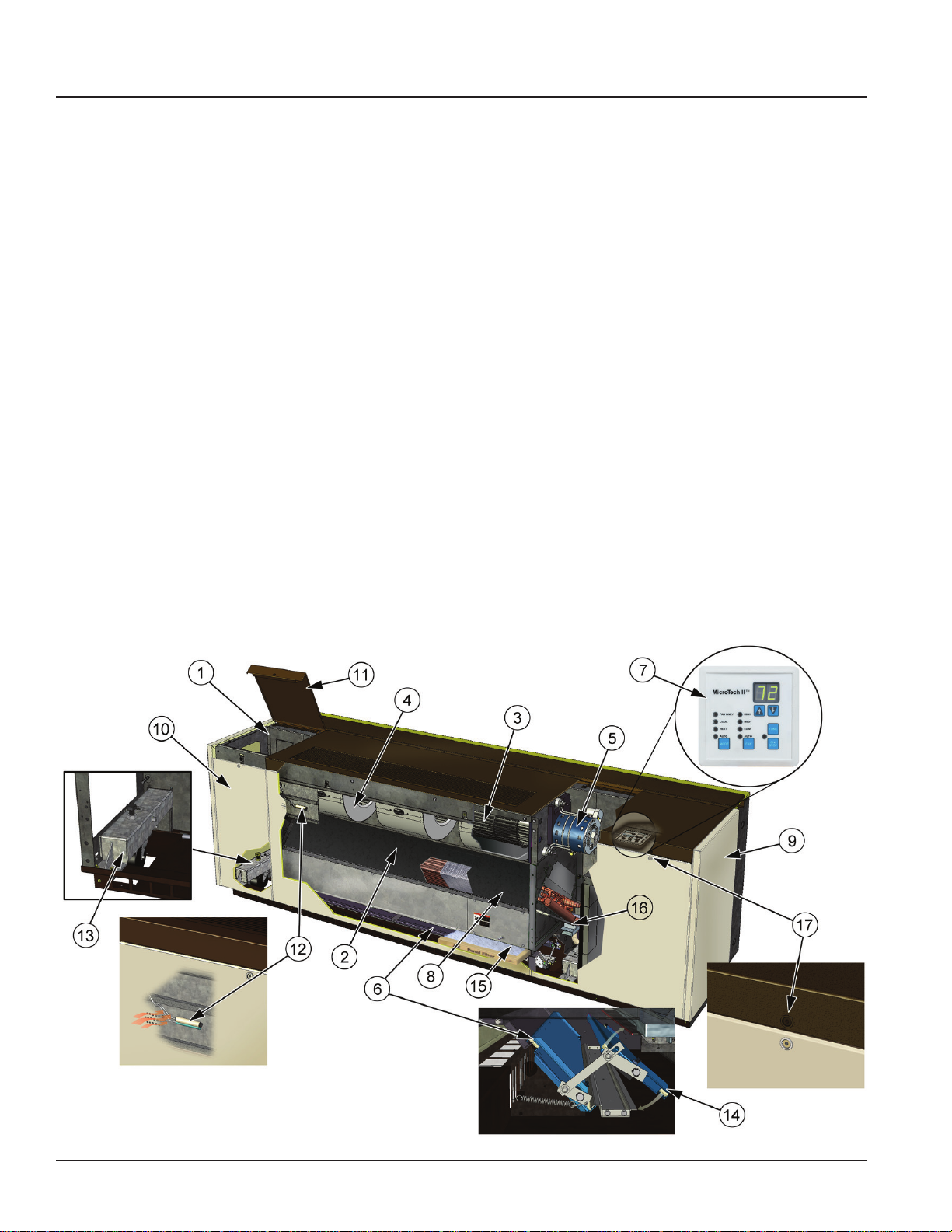
Models AEQ Air Source Heat Pump Self-Contained Unit Ventilator
Our model AEQ is a vertical, oor standing unit that
utilizes refrigerant for cooling and heating. The model
AEQ, size 024 is just right for new construction and for
retrot applications. Unit sizes 036, 044 and 054 are for
replacement applications only, not to be installed in new
construction projects in accordance with ASHRAE 90.1
Older buildings with baseboard radiant heat or other
hydronic heating systems can be easily adapted to work
efciently with the model AEQ unit. The major features
of this model are shown below and described in more
detail on the following pages.
1 Welded One-Piece Chassis offers
superior strength, durability, and
vibration reduction.
2 Unique Draw-Thru Design provides
uniform air distribution across the coil
for even discharge air temperatures.
3 Quiet, Aerodynamic Fans utilize
GentleFlo technology for exceptionally quiet unit operation.
4 Modular Fan Section improves
balance, alignment and simplies
maintenance.
5 Fan Motor Located Out of Air
Stream and away from heating coil
reduces heat exposure to prolong
life.
6 Outside Air/Return Air Damper &
Linkage Provides superior mixture of
outdoor air and room air for precise
temperature control.
7 MicroTech II Controls provide
superior comfort control and easy
integration into the building automation system of your choice.
8 Advanced Heat Transfer Coil de-
sign provides extra capacity.
9 Sturdy Cabinet Construction
includes hidden reinforcement, a
non-glare textured surface, and a
tough, scuff- and mar-resistant nish
to stand up to the abuses of a classroom environment.
10 Sectionalized Front Access Pan-
els provide easy access to unit inte-
rior. Panels are easily removed by a
single person. Front side panels can
be removed while unit is running.
11 Two Hinged Top Access Doors
provide easy access to the motor,
electrical, and refrigeration
components.
12 Sampling Chamber for unit-
mounted sensor provides accurate
sensing of room temperature.
13 Optional Adjustable Caster (Left
and Right Ends).
14 Insulated Double-Wall Outdoor
Air Damper seals tightly without
twisting.
15 Full-length Air Filter is efcient
and easy to replace. All air deliv-
ered to classroom is ltered.
16 Corrosion Proof Sloped Drain
Pan
17 Tamper Resistant Fasteners on
Access Panels
AAF-HermanNelson Model AEQ Unit Ventilator 5
Page 6
Features and Benets
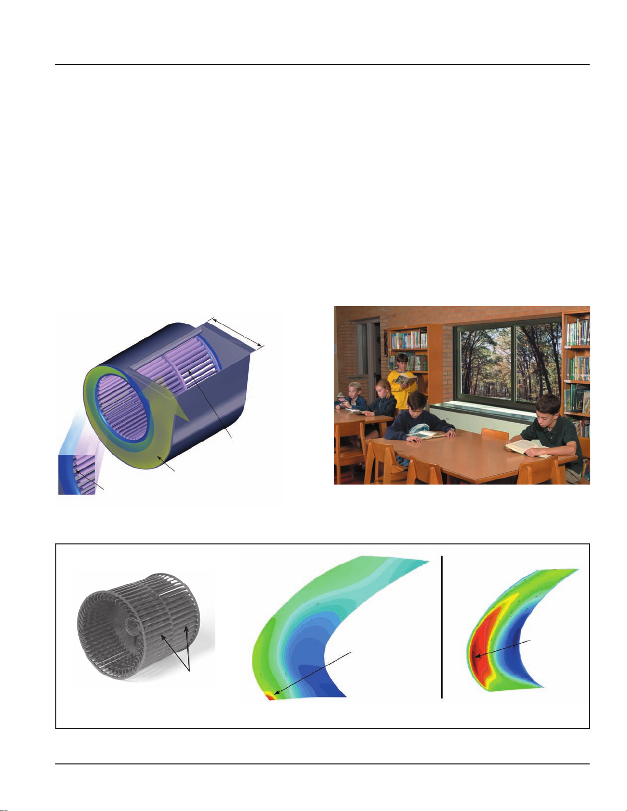
GentleFlo Delivery
AAF-HermanNelson unit ventilators are engineered
and manufactured to deliver quiet, continuous comfort.
We developed our GentleFlo™ air moving system to
minimize operating sound levels – even as demands for
more fresh air require units to operate longer and work
harder. GentleFlo features include:
• Fan wheels are large, wide and rotate at a low
speed to reduce fan sound levels. They are impactresistant and carefully balanced to provide consistent performance.
• Offset, aerodynamic fan wheel blades move air
efciently (Figure 1).
• Precision tolerances help reduce ow and pressure
turbulence, resulting in lower sound levels.
Figure 1: GentleFlo Fan Technology
Expanded Discharge
Air Opening
• Fan housings incorporate the latest logarithmic-
expansion technology for smoother, quieter air ow
(Figure 2).
• A large, expanded discharge opening minimizes air
resistance, further lowering sound levels.
• Modular fan construction contributes to equal outlet
velocities and promotes quiet operation.
• Fan shafts are of ground and polished steel to mini-
mize deections and provide consistent, long-term
operation.
• Fan assemblies are balanced before unit assembly,
then tested after assembly (and rebalanced if necessary) to provide stable, quiet operation.
Offset Aerodynamic Blades
Logrithmic Expansion Housing
Precision T olerances
Figure 2: GentleFlo Reduces Turbulence
High
Minimal
Turbulence
Offset Aerodynamic
Blades
GentleFlo Fan Blade Design Typical Fan Blade Design
Turbulence
6 AAF-HermanNelson Model AEQ Unit Ventilator
Page 7
Features and Benets
The Right Amount of Fresh Air and
Cooling
AAF-HermanNelson unit ventilators deliver required
amounts of fresh air to meet ventilation requirements
and added cooling capacity to maintain consistent
comfort for students and teachers. Our Economizer
Operation, Demand Control Ventilation (DCV) and Part
Load, Variable Air options allow you to match classroom
comfort requirements even more closely, and reduce
operating costs.
This means that you can be condent that your school
is meeting ventilation standards for Indoor Air Quality
and that your students are receiving adequate air to be
attentive to instruction. At the same time, you are saving
money in early morning hours, between classes or after
hours when classrooms are heated and cooled but not
always fully occupied.
Economizer Operation
It is well recognized that cooling, not heating, is the
main thermal challenge in school classrooms. The
typical classroom is cooled by outdoor air over half
the time, even in cold climates. It is therefore essential
that unit ventilators efciently deliver outdoor air when
classroom conditions call for “free” or economizer
cooling.
With AAF-HermanNelson unit ventilators, you can
have outdoor air whenever it is needed. Economizer
operation is facilitated by the outdoor air damper, which
automatically adjusts the above-minimum outside
air position to provide free cooling when the outdoor
air temperature is appropriate (Figure 3). On units
equipped with MicroTech II controls, three levels of
economizer control are available (see See “Economizer
Modes” on page 14).
Figure 3: Full Economizer Mode
100% Outdoor Air Into Classroom
Part-Load Variable Air Control
Part Load Variable Air control can be used in
conjunction with face and bypass damper temperature
control to automatically adjust the unit ventilator
fan speed based upon the room load and the room
temperature. This MicroTech II control option provides
higher latent cooling capabilities and quieter operation
during non-peak load periods by basing indoor fan
speed upon room load. Lower fan speeds in conjunction
with our GentleFlo fan technology contributes to a very
quiet classroom environment.
Room-temperature PI control loops determine the
speed of the fan, which varies according to the
room load. It also provides a built-in delay to prevent
overshooting for better comfort control. The outdoor air
damper’s minimum-air position is adjusted with the fan
speed to bring in a constant amount of fresh air.
Precise Temperature and Dehumidication Control
AAF-HermanNelson unit ventilators provide precise
temperature and dehumidication control to keep
students and teachers comfortable while making
maximum use of “free” outdoor-air cooling to reduce
operating costs. They utilize a draw-thru fan design
that contributes to even heat transfer and provides
uniform discharge air temperatures into the classroom.
MicroTech II control strategies and 2-stage compressor
operation, provide precise control of temperature and
humidity levels under both part-load and full-load
conditions.
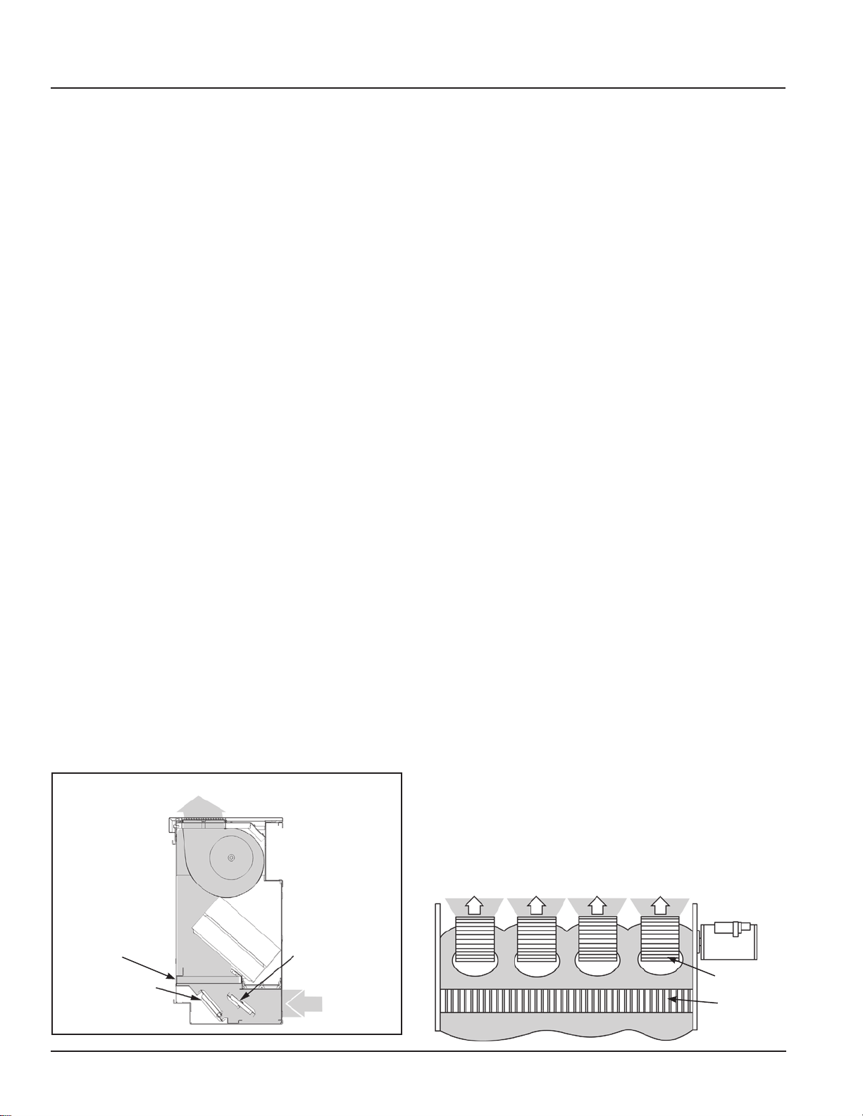
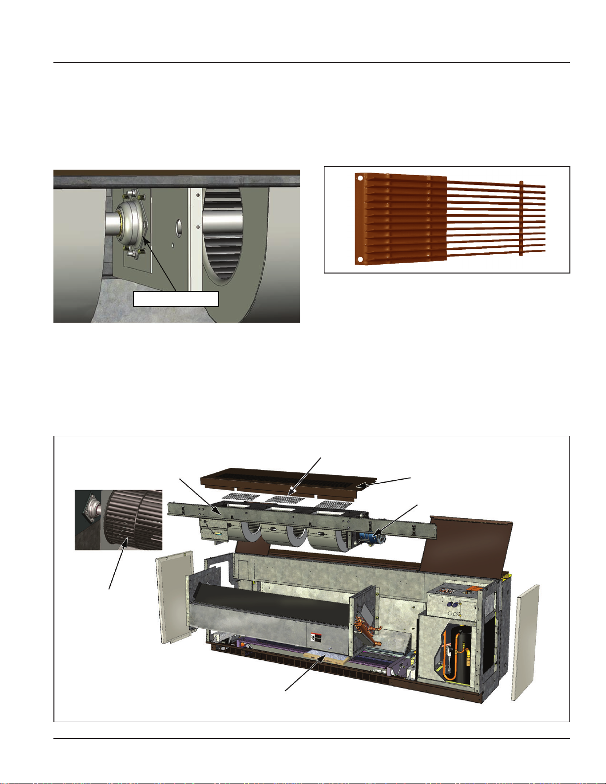
Draw-Thru Design For Even Discharge
Temperatures
The AAF-HermanNelson Draw-Thru design sets our unit
ventilators apart from most competitive models. With
this system, fans draw air through the entire heat transfer element (Figure 4) rather than blowing it through
highly concentrated areas of the coil element. The result
is more uniform discharge air temperatures into the
classroom and more efcient unit ventilator operation.
Figure 4: Draw-Thru Design Provides Even Discharge Air
Uniform Discharge Air (Shaded)
Motor
Filter
Room Air Damper
AAF-HermanNelson Model AEQ Unit Ventilator 7
Outdoor Air Damper
Outdoor Air
Fans
Condenser
Page 8
Features and Benets
Figure 5: Draw-Thru Vs. Blow-Thru Design
Coil
Coil
Room Air
Damper
Room Air
AAF-HermanNelson
Draw-Thru Design
Outdoor Air
Damper
Outside Air
Filter
RA/OA
Divider
Room Air
Outside Air
Blow-Thru Design
Low Installation Costs
Perfect For Both New Construction (Size
024) & Retrot Applications
New construction installations are easily accomplished
with the AAF-HermanNelson AEQ size 024 air source
heat pump unit ventilator because of the avoided added
cost and space required for expensive duct work. This is
important in existing buildings and also in new construc-
tion where oor-to-oor heights can be reduced, saving
on overall building costs. Further savings can be realized because air source heat pump self-contained unit
installations use less space than units that require water
supply and return piping.
Retrot installations are economical because new units
typically t the same space occupied by existing ones.
Built In Flexibility
AAF-HermanNelson unit ventilators include features
that make them easy to set up and recongure as
needed to meet special requirements. These features
include:
• Built-In Wire Race A built-in metal wire race runs
from one end of the unit to the other to provide extra
protection for wires and protect them from unit air.
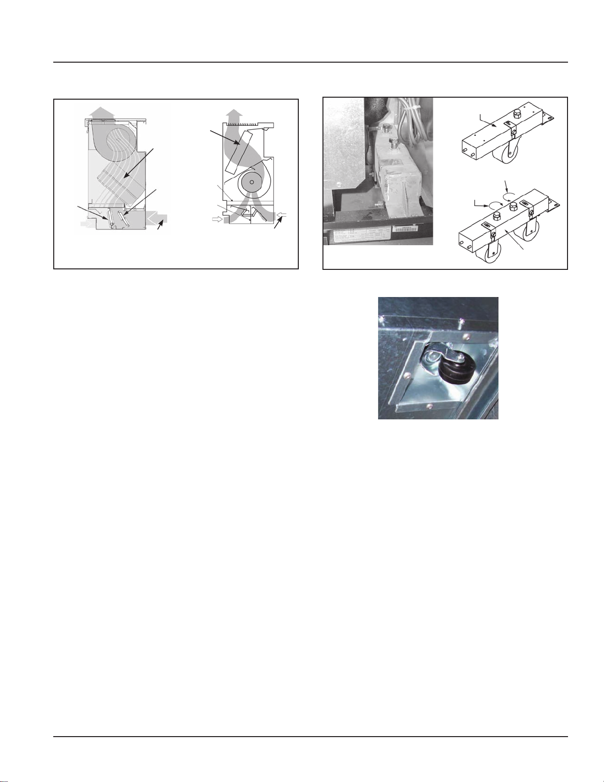
Figure 6: Optional Unit Casters
Left Caster
Counter-clockwise to lower
Clockwise to raise
Casters can be adjusted
Figure 7: Condenser Casters
Condenser casters ease installaiton. Optional unit casters can
be adjusted.
Right Caster
Controls Flexibility
Multiple control options—including MicroTech II controls
with our Protocol Selectability feature—provide easy,
low cost integration of AAF-HermanNelson unit ventilators into the building automation system of your choice
(See “MicroTech II Controls” on page 13). You can also
operate these units individually or in a master-servant
control conguration.
With MicroTech II controls, you can select BACnet, LonTalk or Metasys N2 communications to communicate
control and monitoring information to your BAS, without
the need for costly gateways. Unit controllers are LONMARK certied with the optional LonWorks communica-
tion module.
8 AAF-HermanNelson Model AEQ Unit Ventilator
Page 9
Features and Benets
Low Operating Costs
Schools consume more than 10% of the total energy
expended in the United States for comfort heating and
cooling of buildings. As energy costs increase, educators are placed in a difcult position: caught between rising costs, lower budgets and the requirements to raise
educational standards.
Fortunately, the technology and the system exists for
schools to take control of their energy expenditures
while providing a comfortable environment for learning.
And that system is the AAF-HermanNelson unit
ventilator.
Consider these realities of school environments:
• Most heating energy in schools is expended to heat
unoccupied spaces. Because lights, computers
and students give off considerable heat, occupied
spaces require little supplemental heat.
• The removal of heat is usually required in occupied
classrooms, even when outside temperatures are
moderately cold (i.e., 35 to 40°F).
• Then consider how AAF-HermanNelson unit ventilators, located in each classroom, take advantage of
these realities to lower operating costs:
• They provide individual classroom control and
comfort.
• They can be cycled on when the room is occupied
and cycled off when it is not.
• They bring in fresh air from directly outside the
classroom for high indoor air quality.
• During most of the school year, they use outdoor air
to keep classrooms comfortable without the expense of mechanical cooling.
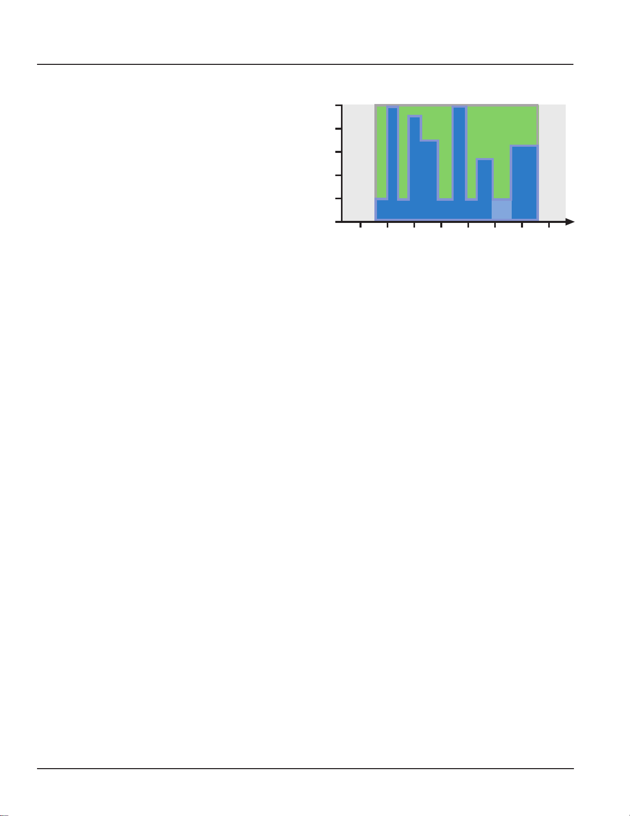
Figure 8: Energy Savings with Demand Control Ventilation
100%
Energy Savings
with DCV
20%
Unoccupied
DCV's fresh air for indoor air quality
6:00 8:00 10:00 12:00 2:00 4:00 6:00 8:00
School Hours
Cleaning
Unoccupied
After Hours
• Occupancy Mode Operation Units can be pro-
grammed to operate only sparingly during unoccupied periods and at night to conserve energy.
Two-Stage Compressor
Air conditioning units are usually sized for worse case
conditions. During high load requirement the unit
will operate in high fan speed and high compressor
capacity. Most of the time there is not a full load on
the compressor. Operation in lower load will be at
medium or low fan speeds which will be at the lower
displacement compressor stage. The two stage
compressor will remain at low speed until more cooling
is required. With the two-stage compressor, the unit
will run on lower fan speeds most of the time improving
comfort through better humidity control and quieter
operation, while minimizing issues with over-sizing.
Other units utilizing single stage compressors operate at
full compressor capacity all of the time regardless of fan
speed.
MicroTech II Control Options Further
Reduce Operating Costs
• Many of the MicroTech II control options available
with AAF-HermanNelson unit ventilators can further
reduce operating costs. For example:
• Economizer Operation Economizer operation automatically adjusts the above-minimum outside air
position to provide free cooling when the outdoor air
temperature is appropriate.
• Demand Control Ventilation By using CO2 levels
to monitor the actual occupancy pattern in a room,
the system can allow code-specic levels of outdoor air to be delivered when needed without costly
over-ventilation during periods of low or intermittent
occupancy (Figure 8).
AAF-HermanNelson Model AEQ Unit Ventilator 9
Page 10
Features and Benets
Easy To Maintain
Fan Deck
The fan deck’s rotating element has one large, selfaligning, oilable end bearing for smoother operation.
Figure 9: Long-Life Bearings
Long Life Bearing
Even “permanently” lubricated motors are supplied with
recommended lubrication charts calling for lubrication
every seven years. Maintenance instructions of the
motor manufacturer should be followed closely.
Figure 11: Fan Deck
Heavy-Duty Discharge Grille
The discharge grille on the top of the unit is made
from extra-strength steel bar stock, promoting long life
(Figure 10). It can be removed to facilitate cleaning of
fans and fan housings.
Figure 10: Heavy-Duty Steel Discharge Grille
Internal Fan Deck Components
Unlike with many competitive models, the motor in
AAF-HermanNelson unit ventilators is separate from
the fan assembly and is located out of the airstream at
the end of the fan shaft—away from the hot coil—for
easier maintenance and removal. Locating the motor
away from the coil (Figure 11) has the added benet of
extending motor life. Our direct-coupled motor and selfaligning motor mount facilitate motor change-out. The
motor comes with a molex plug that ts all sizes and
further simplies removal.
Aerodynamic Fans
Modular Fan Deck
1/4" Mesh Screens Protects Against Objects Dropping into Fan Housings
Heavy-Duty Discharge Grille
Motor Located Out of Airstream
Filter
10 AAF-HermanNelson Model AEQ Unit Ventilator
Page 11
Features and Benets
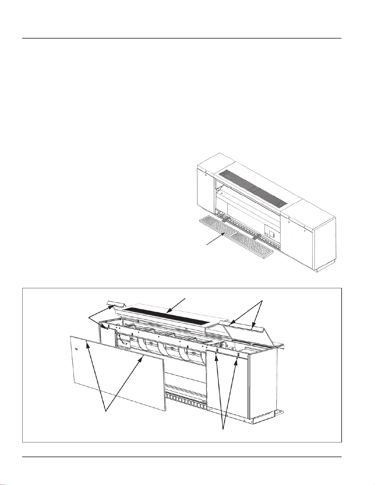
Tamper-Resistant Fasteners
Front panels and top access doors are held in place by
tamper-resistant, positive-positioning fasteners. They
are quickly removed or opened with the proper tool, but
deter unauthorized access to the unit’s interior (Figure
12).
Sectionalized Access Panels and Doors
All units have three separate front panels and hinged
top access doors, sized for convenient handling by a
single person (Figure 12). The result is easy, targeted
access to the component that needs servicing:
• Two end panels provide easy access to piping,
temperature control components and the fan switch.
Unlike units with full-length front panels, these can
be removed without disturbing the normal operation
of the unit.
• Hinged top access doors provide easy access
into the end compartments to facilitate convenient
servicing of the motor, electrical, and refrigeration
components.
• Center front panel provides easy access to the lter
and the fan shaft bearing on unit sizes 044 and 054.
Filter
Three lter types are offered:
• Units come standard with a single-use lter which is
designed to be used once and discarded.
• Optional, permanent metal lters are available and
can be removed for cleaning and reused numerous
times.
• Renewable media lters, which consist of a heavy-
duty, painted-metal structural frame and renewable
media.
Figure 13: Easy Access to Filter
Figure 12: Easy Access with Tamper-Resistant Fasteners
Tamper Resistant Fasteners
Tamper Resistant Fasteners
Removable Filter
Discharge Grille
Tamper Resistant Fasteners
Tamper Resistant Fasteners
AAF-HermanNelson Model AEQ Unit Ventilator 11
Page 12
Features and Benets
Built To Last
Durable, Energy Efcient Fan Motors
AAF-HermanNelson unit ventilators are equipped with
115/60/1 NEMA motors that feature low operating
current and wattage (Figure 14).
Figure 14: Energy-Efcient Fan Motor
Energy Efcient NEMA Motor
Decoupled Isolation System
Additional features of these motors include:
• Split-capacitor (PSC) design with automatic reset
and thermal-overload protection.
• No brushes, contacts or centrifugal starting switch-
es – the most common causes of motor failure.
• A built-in, decoupled isolation system to reduce
transmission of vibrations for quieter operation.
• A multi-tap, auto-transformer (Figure 15) provides
multiple fan motor speed control through the speed
switch. The motor is independent of supply voltage,
which allows stocking of one motor (school districtwide) for various voltage applications.
Figure 15: Multi-Tap Auto-Transformer
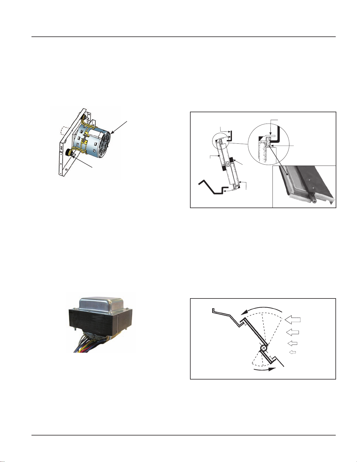
Additional features include:
• Outdoor air dampers are made of galvanized
steel to inhibit corrosion, with double-wall welded
construction for rigidity and encapsulated insulation
(Figure 16). Additional insulation is provided on the
exterior of the outdoor air damper blade and on the
outdoor air entry portion of the unit.
Figure 16: Outdoor Damper Seals Out Cold Weather
Turned Metal Damper Stop
Wool Mohair
End Seal
Additional
Insulation
Wool Mohair
End Seal
Turned Metal Damper Blade
Full-Length Wool
Mohair Damper
• Room air dampers are free-oating and designed
to prevent intermittent gusts of cold air from blowing directly into the classroom on windy days
(Figure 17). They are constructed of aluminum with
built-in rigidity. The metal forming technique that is
employed resists twisting and incorporates a fulllength counter weight for easy rotation. The simple
principle of an area exposed to a force is used to
automatically close the damper, rather than open it,
when gusts of cold air occur.
Figure 17: Room Air Damper Auto-Closed By Wind Gusts
Wind
Gust
Durable Damper Design
All dampers in AAF-HermanNelson Unit Ventilators use
the turned-metal principle on their long closing edges
(Figure 16). Positive sealing is provided by embedding
the edge into wool mohair (no metal to metal contact).
There are no plastic gaskets to become brittle with time,
sag with heat or age, or require a difcult slot t to seal.
Nylon damper bearings foster quiet, maintenance-free
operation.
12 AAF-HermanNelson Model AEQ Unit Ventilator
Page 13
MicroTech II Controls
MicroTech II Controls For Superior Performance, Easy Integration
AAF-HermanNelson unit ventilators equipped with MicroTech II
unit controllers can provide superior performance and easy integration into your building automation system of choice. MicroTech II
benets include:
• Factory integrated and tested controller, sensor,
actuator and unit options promote quick, reliable
start-up and minimize costly eld commissioning.
• High-performance features and advanced control
options can quickly pay for themselves in saved
energy costs and more comfortable classrooms.
• Select from three control levels: stand-alone,
master-servant or network control.
• For network control applications, our Protocol
Selectability feature provides easy, low-cost integration of AAF-HermanNelson unit ventilators into most
building automation systems.
• Flexible BAS network communication options guard
against controls obsolescence, keeping MicroTech
II controls viable for the life of your AAF-HermanNelson equipment.
Three Control Levels
MicroTech II unit controllers provide the exibility to
operate AAF-HermanNelson unit ventilators on any of
three levels:
• As stand-alone units, with control either at the unit
or from a wall sensor.
• In a master-servant relationship, where servant
units follow the master unit for some or all functions.
• Controlled as part of a network using a centralized
building automation system.
Stand-Alone Control
• When operating in stand-alone mode, the MicroTech II controller performs complete room temperature and ventilation control. Units can be operated in
occupied, unoccupied, stand-by, or bypass (tenant
override) modes. Occupied/unoccupied changeover
can be accomplished:
• Manually by a unit-mounted occupied/unoccupied
switch.
• Automatically by a unit-mounted occupied/unoccupied time clock.
• Automatically by a remote-mounted time clock that
operates unit-mounted day/night relays.
• If a school has more than one zone, separate, remote time clocks are used to regulate each zone. In
this case, the remote-mounted time clock energizes
or de-energizes an external, 24-volt or 120-volt
control circuit which operates the unit-mounted day/
night relays in that zone.
Master-Servant Control
Designate the master and servant units and we will
factory congure and install the controllers so they are
set up for a local peer-to-peer network between units
(leaving only the network wiring between these units to
be eld installed).
Servant units can be eld-congured to be dependent or
independent as follows:
• Dependent servant units follow the master unit
completely. They are ideal for large spaces that
have even loads across the space (such as some
libraries).
• Independent servant units (default) use master setpoints and servant sensors. The servant follows the
master unit modes, such as heat or cool, but has
the exibility to provide the conditioning required for
its area within the space. Independent servant units
perform better in spaces where loads vary from one
area of the space to the other (such as stairwells or
cafeterias).
Network Control
MicroTech II unit controllers provide easy integration
into your building automation system of choice. All
factory-installed options are handled by the unit control-
ler. This simplies the transmission of monitoring and
setpoint data to the building automation system.
You select BACnet, LonTalk or Metasys N2 Open
communications to communicate control and monitoring
information to your BAS, without the need for costly
gateways (see “Optional Communication Modules” on
page 18). Unit controllers are LONMARK certied with
the optional LonWorks communication module.
Flexible network communication options via our Proto-
col Selectability feature help you avoid control obsolescence over the life of your AAF-HermanNelson equipment.
AAF-HermanNelson Model AEQ Unit Ventilator 13
Page 14

MicroTech II Controls
Control Modes and Functions
AAF-HermanNelson unit ventilators equipped with
MicroTech II unit controllers can be programmed to
operate in a variety of modes based on the current
situation in the room and the status of the unit ventilator.
Changes in mode can be triggered manually, via
network signals, by sensor readings, or by date and
time. External inputs and outputs can be used to
change modes, communicate data to network controls
or change the functional operation of the unit.
Occupancy Modes
MicroTech II unit controllers can be set up to change
modes based on room occupancy. Four different
occupancy modes are provided, as described below.
Occupied Mode
This is the normal daytime operation mode. The
controller maintains a room set point using the outside
air capability and other functions.
Note: For non-school applications, the unit can also
be congured to cycle the fan in response to the
room load. In this case, the fan would normally
be in the Off Mode until heating or cooling is
required. The outside air damper is always closed
when the fan is off. When the fan starts, the
outside air damper opens to the required position,
usually minimum position.
Unoccupied Mode
This is the night setback operating mode, in which the
unit responds to a new room set point and cycles to
maintain the condition. The fan comes on when heating
or cooling is needed and runs until the load is satised.
The outdoor air damper is closed during this mode.
When a cooling load is satised by a refrigerant system,
the compressor is de-energized and the unit ventilator
indoor fan continues to run for a xed period of time to
remove coldness from the evaporator coil.
Stand By Mode
In this mode, the unit maintains the occupied mode set
point temperature with the outdoor air damper closed.
The fan runs continuously unless it is congured to
cycle in response to the load.
Bypass Mode
This is a tenant override operating mode in which
the unit is placed back into the Occupied Mode for
a predetermined time. The default is 120 minutes.
Settings can be made in 1-minute increments from
1 minute to 240 minutes through the Unit Ventilator
Service Tool or a network.
Economizer Modes
Economizer operation is facilitated by the outdoor
air damper, which automatically adjusts the aboveminimum outside air position to provide free cooling
when the outdoor air temperature is appropriate. Three
levels of economizer control are available:
Basic Economizer Operation:
The MicroTech II controller compares the inside and
outside temperatures. If the temperature comparison is
satisfactory, then free-air economizer operation is used
to cool the space. Reheat units also come congured
with an indoor humidity sensor.
Expanded Economizer Operation:
In addition to comparing inside and outside
temperatures, outdoor relative humidity is measured
to calculate outside air enthalpy. Free economizer
operation is used to cool the space. This helps to
minimize the entrance of humid outside air.
Leading-Edge Economizer Operation:
The MicroTech II controller compares both indoor and
outdoor temperatures and indoor and outdoor relative
humidities to determine if free economizer operation can
cool the space with non-humid outside air. This is a true
enthalpy economizer.
Night Purge Mode
Under this mode, the unit is congured to purge the
room space for one hour for various reasons (odor
or fume removal, drying, etc.).During Night Purge the
outside air damper is open full and the fan is run on
high speed. No “normal” heating or cooling takes place
(the emergency heat set point is maintained) and the
exhaust fan, if the room is so equipped, is signaled to
turn on.
Freeze Prevention Mode
This mode helps protect the unit ventilator from freezing
air conditions. Control functions vary depending on the
type of temperature control used by the unit, as follows:
Emergency Heat Mode
If the unit is left in a mode that does not normally allow
heating (such as Off, Fan Only, Cool, or Night Purge)
and the room temperature falls below 55°F, the unit
will heat the space to above 55°F and then return to
the previously set mode of operation. This mode of
operation can be eld congured and/or be disabled.
14 AAF-HermanNelson Model AEQ Unit Ventilator
Page 15

MicroTech II Controls
External Input Functions
The unit ventilator controller is provided with three (3)
binary inputs that allow a single set of dry contacts to be
used as a signal to it. Input signal choices are described
below. Multiple units can be connected to a single set of
dry contacts.
Note: Not all of the functions listed can be used at the
same time. The unit ventilator controller is pro-
vided with conguration parameters that can be
adjusted to select which function will be used for
these inputs where multiple functions are indi-
cated below. For wiring examples see installa-
tion manual IM 747: MicroTech II Unit Ventilator
Controller.
Unoccupied Input Signal
This input signals the unit ventilator controller to go
into unoccupied or occupied mode. When the contacts
close, the unit ventilator controller goes into unoccupied
mode; when the contacts open, it goes into occupied
mode. Additional variables can affect occupancy mode
and override this binary input. See “Occupancy Modes”
on page 14.
Dewpoint/Humidity Input Signal (Optional)
This input signals the unit ventilator controller to go
into active dehumidication mode. When the contacts
close (high humidity) the controller will go into active
dehumidication; when the contacts open (low humidity)
it will stop active dehumidication.
Remote Shutdown Input Signal
This input signals the unit ventilator controller to go into
shutdown mode. When the contacts close, the controller
goes into shutdown mode; when the contacts open, it
returns to normal operation.
Ventilation Lockout Input Signal
This input signals the unit ventilator controller to close
the outdoor air damper. When the contacts close
(ventilation lockout signal) the controller closes the
outdoor damper; when the contacts open, it returns to
normal outdoor damper operation.
Exhaust Interlock Input Signal
This input signals the unit ventilator controller that an
exhaust fan within the space has been energized. The
controller then repositions the outdoor air damper to a
user-adjustable minimum position. When the contacts
close (exhaust fan on signal) the controller uses the
value dened by the Exhaust Interlock OA Damper
Min Position Setpoint as the new minimum outdoor air
damper position regardless of the indoor air fan speed.
When the contacts open, it returns to normal outdoor
damper operation.
External Output Functions
The unit ventilator controller is provided with three (3)
binary outputs to perform the functions described below.
These are relay type outputs that are intended to be
used with signal level voltages only (24 VAC max).
Note: Not all of the functions listed can be used at the
same time. The unit ventilator controller is pro-
vided with conguration parameters that can be
adjusted to select which function will be used for
these outputs when multiple functions are indi-
cated below. For wiring examples, see installa-
tion manual IM 747: MicroTech II Unit Ventilator
Controller.
Lights On/Off Signal
This relay output provides one set of NO dry contacts
that can be used to signal the operation of the room
lights. When the unit ventilator controller is in occupied,
standby or bypass occupancy modes, the relay output
will signal the lights on (contacts closed); when the
controller is in unoccupied occupancy mode the relay
output will signal the lights off (contacts open).
Fault Signal
This relay output provides NO, NC, and Common
connections that can be used to signal a fault condition.
When a fault exists, the unit ventilator controller
energizes this relay output. When the fault or faults are
cleared, it de-energizes this relay output.
Exhaust Fan On/Off Signal
This relay output provides one set of NO dry contacts
that can be used to signal the operation of an exhaust
fan. When the outdoor air damper opens more than the
Energize Exhaust Fan OA Damper Setpoint, the relay
output will signal the exhaust fan on (contacts closed).
When the outdoor damper closes below this setpoint,
the relay output will signal the exhaust fan off (contacts
open).
Auxiliary Heat Signal
This relay output provides one set of NO dry contacts
that can be used to operate an auxiliary heat device.
The unit ventilator controller by default is congured to
operate a NO auxiliary heat device (de-energize when
heat is required) such as a wet heat valve actuator with
a spring setup to open upon power failure. However,
the Auxiliary Heat Conguration variable can be used
to set the controller to use an NC auxiliary heat device
(energize when heat is required) such as electric heat.
AAF-HermanNelson Model AEQ Unit Ventilator 15
Page 16

MicroTech II Controls
Advanced Control Options
MicroTech II controls make possible a number
of advanced control options that can quickly pay
for themselves in saved energy costs and more
comfortable classrooms, as described below.
Part Load Variable Air Control
Part Load Variable Air control can be used to
automatically adjust the unit ventilator fan speed based
upon the room load and the room-temperature PI
control loop. This MicroTech II control option provides
higher latent cooling capabilities and quieter operation
during non-peak load periods by basing indoor fan
speed upon room load.
During low-load or normal operation (about 60% of
the time) the fan will operate on low speed. When the
load increases to an intermediate demand, the fan
will automatically shift to the medium-speed setting.
Under near-design or design-load conditions, the fan
will operate on high speed. A built-in, 10-minute delay
helps minimize awareness of fan speed changes. Lowspeed fan operation under normal operating conditions,
in conjunction with our GentleFlo fan technology
contributes to a very quiet classroom environment.
Demand-Controlled Ventilation (Optional)
AAF-HermanNelson unit ventilators can be equipped to
use input from a CO2 controller to ventilate the space
based on actual occupancy instead of a xed design
occupancy. This Demand Controlled Ventilation (DCV)
system monitors the amount of CO2 produced by
students and teachers so that enough fresh outdoor air
is introduced to maintain good air quality. The system
is designed to achieve a target ventilation rate (e.g., 15
cfm/person) based on actual occupancy.
By using DCV to monitor the actual occupancy pattern
in a room, the system can allow code-specic levels of
outdoor air to be delivered when needed. Unnecessary
over-ventilation is avoided during periods of low or
intermittent occupancy.
With DCV you can be condent that your school is
meeting ventilation standards for Indoor Air Quality
and that your students are receiving adequate air to be
attentive to instruction. At the same time, you are saving
money in early morning hours, in between classes, or
after hours when classrooms are heated and cooled but
not always fully occupied.
Acceptance by Codes and Standards
ASHRAE Standard 62-2004 Ventilation for Indoor Air
Quality recognizes CO2 based DCV as a means of controlling ventilation based on occupancy. The ASHRAE
standard has been referenced or adopted by most
regional and local building codes. This standard references ventilation on a per-person basis.
Using CO2 control will sometimes lower the absolute
amount of outside air delivered into a room but will
maintain the per-person rate. For example, if a classroom is designed for 30 students, the ventilation rate is
450 cfm (30 students × 15 cfm/student). However, when
there are only ten students in the classroom, the CO2
control will adjust ventilation to 150 cfm (10 students
× 15 cfm/student). A minimum base ventilation rate
(typically 20% of design levels) is provided when in the
occupied mode. This provides outdoor air to offset any
interior source contamination while allowing for proper
space pressurization.
DX System Control
The unit ventilator controller is congured to operate the
compressor as secondary (mechanical) cooling when
economizer cooling is available, and as primary cooling
when economizer cooling is not available. Additional DX
control features include:
Compressor Envelope:
This helps protect the compressor from adverse
operating conditions that can cause damage and
or shortened compressor life. It ends compressor
operation if coil temperatures exceed the dened
operating envelope.
Compressor Cooling Lockout:
The unit ventilator controller is congured to lock out
compressor cooling when the outdoor air temperature
falls below the compressor cooling lock out setpoint.
Below this temperature setpoint only economizer
cooling will be available.
Minimum On and Off Time:
The unit ventilator controller is provided with minimumon and minimum-off timers to prevent adverse
compressor cycling (3-minutes default).
Compressor Start Delay Variable:
This variable is intended to be adjusted as part of the
start-up procedure for each unit. It is used to prevent
multiple unit compressors from starting at the same time
after a power failure or after an unoccupied-to-occupied
changeover. Each unit should be congured at start-
up with a slightly different (random) delay, or groups of
units should be provided with different delays.
16 AAF-HermanNelson Model AEQ Unit Ventilator
Page 17
MicroTech II Controls
System Components
The main components of the MicroTech II system are:
• The Unit Ventilator Controller (UVC)
• The Local User Interface (LUI)
• Optional plug-in network communication modules
In addition, unit ventilators equipped with MicroTech
II controllers feature factory-mounted sensors and
actuators for system control and feedback.
Unit Ventilator Controller
The MicroTech II UVC is a DDC, microprocessor-based
controller designed to provide sophisticated comfort
control of an economizer-equipped AAF-HermanNelson
unit ventilator. In addition to normal operating control,
it provides alarm monitoring and alarm-specic
component shutdown if critical system conditions occur.
Each UVC is factory wired, factory programmed and
factory run-tested for the specic unit ventilator model
and conguration ordered by the customer.
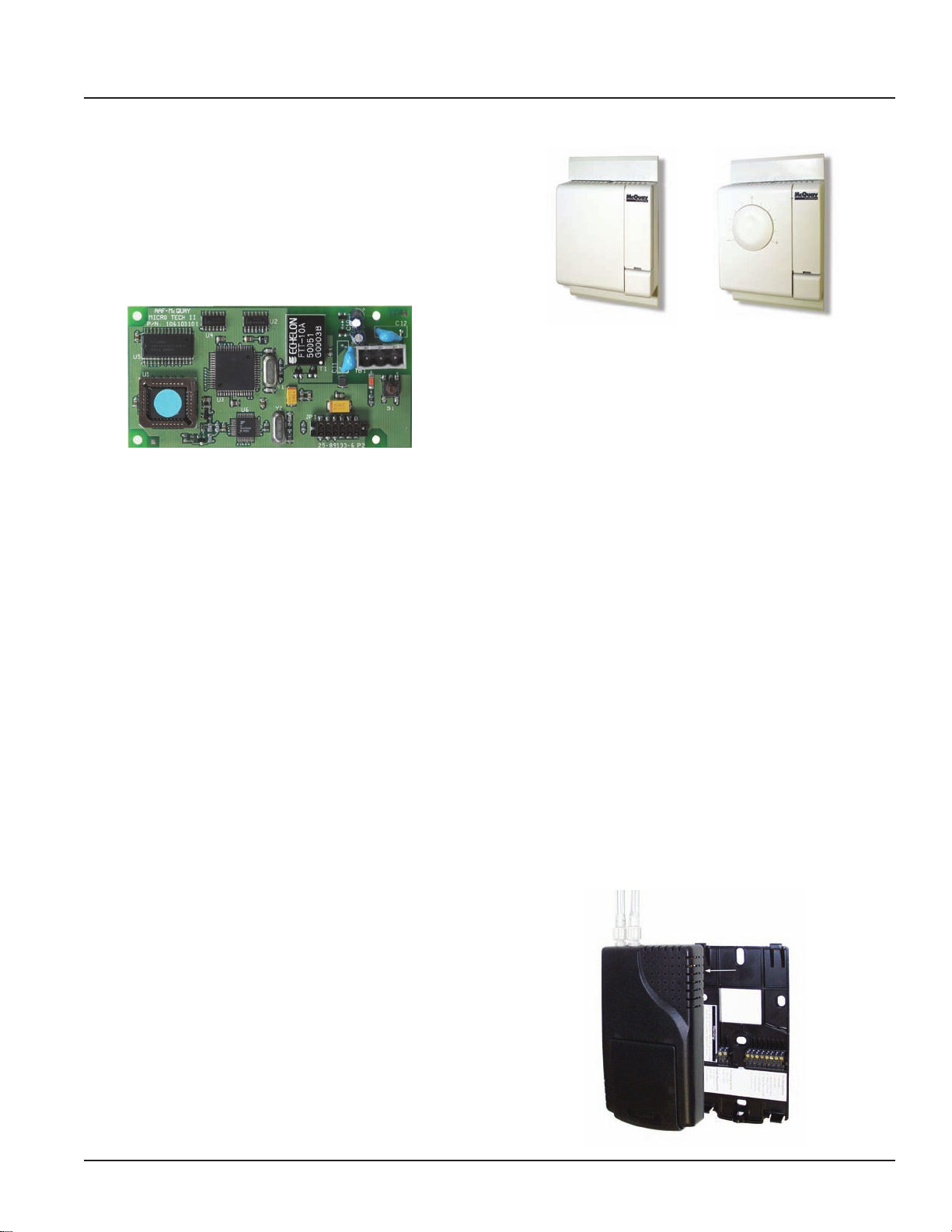
Figure 18: MicroTech II Control Board
Terminal Connections Plug-In Control Module
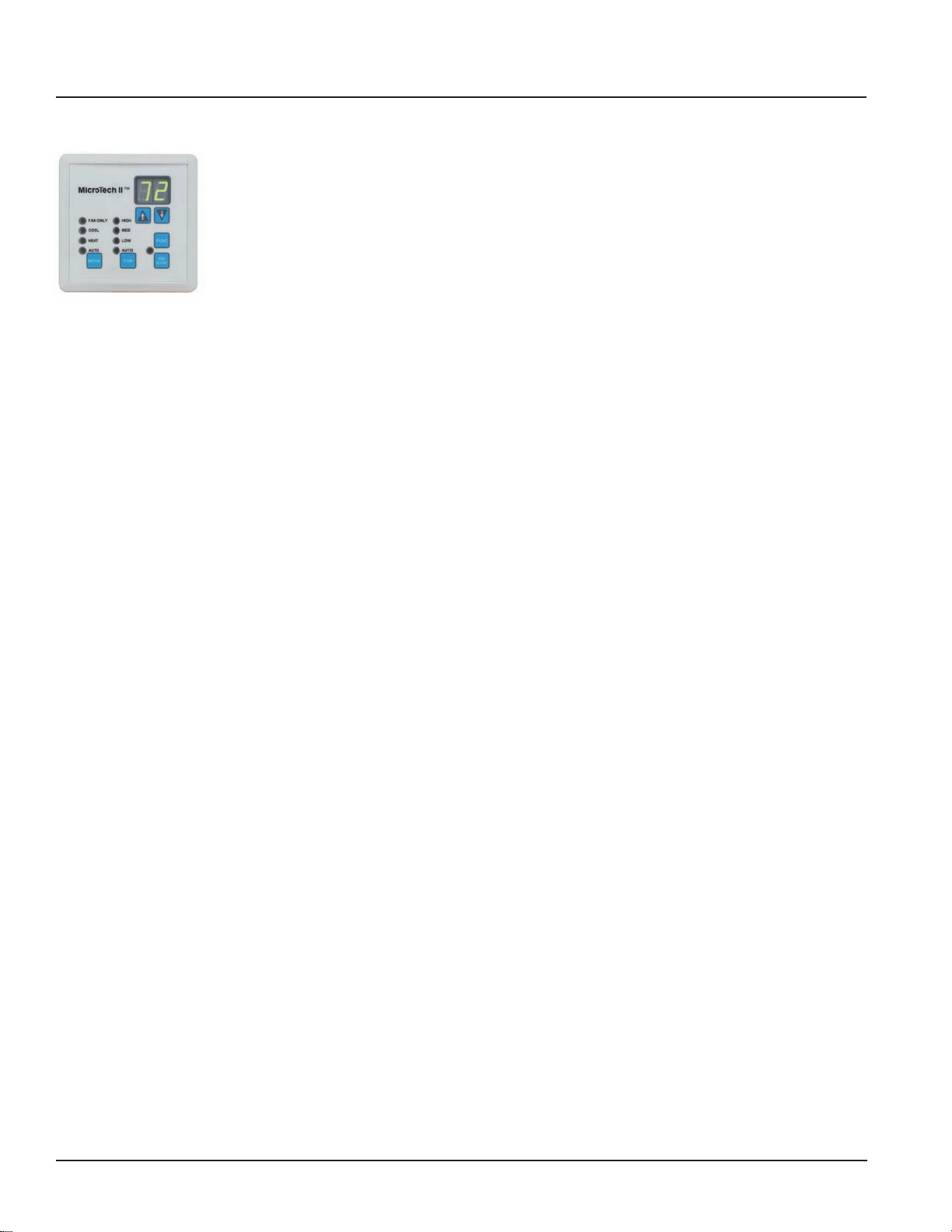
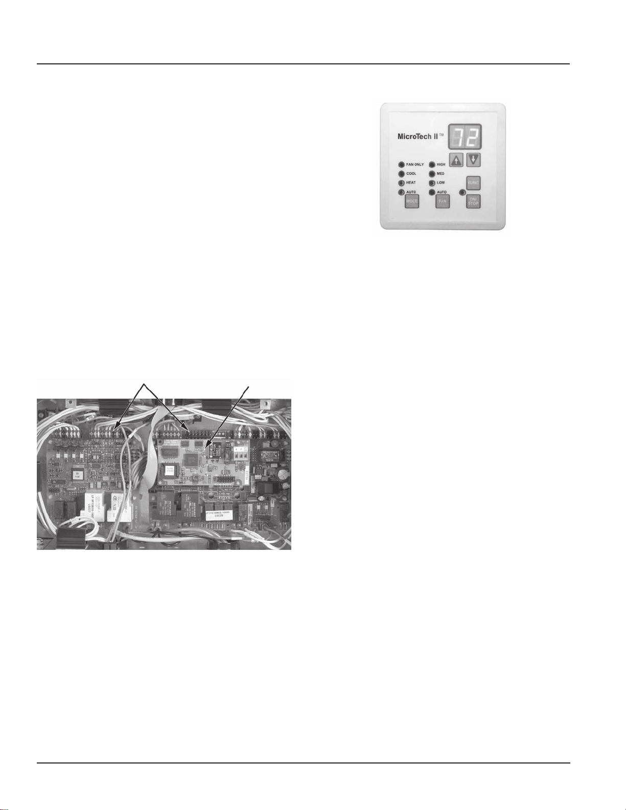
Figure 19: User Interface Touch Pad
The User Interface has individual touch-sensitive printed
circuit board mounted buttons, and comes with a built-in
menu structure (Hidden Key and Password Protected)
to change many of the common operating variables.
Four Operating Mode States
Four different user operating mode states can be
chosen on the LUI:
Heat: Heating and economizer operation only.
Cool: Cooling and economizer operation only.
Fan Only: Fan only operation.
Auto: The unit automatically switches between heating,
cooling and economizer operation to satisfy the room
load conditions. The current unit state is also displayed.
Local User Interface
A built-in LUI touch pad with digital LED Display is
located in the right hand compartment below the top
right access door. In addition to the Operating Mode
States and Fan Functions, the Touch Pad will digitally
display:
• The room set point temperature.
• The current room temperature.
• Any fault code for quick diagnostics at the unit.
Four Fan States
Four fan states are provided on all units: high, medium
low and Auto speed modulation. The Auto speed
function (part load, variable air) varies the fan speed
automatically to meet the room load whether the unit is
in heating, cooling or economizer mode.
All this is accomplished with a standard, single-speed
NEMA frame motor. A built-in 10-minute delay helps
minimize awareness of speed changes. During low-load
or normal operation (about 60% of the time) the fan will
operate at low speed. The low speed operation, along
with GentleFlo fan technology, contributes to a very
quiet classroom environment.
When the load increases to an intermediate demand,
the fan automatically shifts to the medium speed setting.
At near-design or design-load conditions the fan will
operate on high speed.
With four fan states and GentleFlo fan technology,
there is no need to oversize units or worry about
uncomfortable conditions.
AAF-HermanNelson Model AEQ Unit Ventilator 17
Page 18
MicroTech II Controls
Optional Communication Modules
Optional communication modules provide control and
monitoring information to your building automation
system without the need for costly gateways. Available
communication protocols include BACnet, LonTalk and
Metasys N2 Open. The communication modules for
each are described below.
Figure 20: Typical 2" x 4" Communication Module
BACnet MS/TP Communication Module
This module allows the UVC to inter-operate with
systems that use the BACnet (MS/TP) protocol with a
conformance level of 3. It meets the requirements of the
ANSI/ASHRAE 135-1995 standard for BACnet systems.
LonWorks SCC Communication Module
This module supports the LonWorks SCC (Space
Comfort Communication) prole number 8500-10. Unit
controllers are LonMark certied with this optional Lon-
Works communication module.
Figure 21: Wall-Mounted Temperature Sensors
Standard Expanded
Standard Sensor:
This sensor has no remote setpoint adjustment
capability.
Expanded Sensor:
This sensor has a remote room setpoint adjustment
of ±3°F (±1.5°C) from the room setpoint established
on the unit ventilator’s local user interface touch pad.
Five temperature settings are provided on each side of
center.
Humidity Sensors
On units equipped with humidity sensors, the UVC is
congured to use a 0-100% RH, 0 VDC, capacitive
humidity sensor. Humidity sensors are available as unitmounted only. The humidity sensors are used with units
using an outdoor enthalpy economizer or an indoor/
outdoor enthalpy economizer.
Metasys™ N2 Communication Module
This module provides N2 Open network communication
capability to the UVC for communication with Johnson
Metasys systems.
Sensors
The UVC is congured to use passive Positive
Temperature Coefcient (PTC) unit-mounted and
wall-mounted sensors. These sensors vary their input
resistance to the UVC as the sensed temperature
changes.
CO2 Sensor for Demand Controlled Ventilation
On units equipped for Demand Controlled Ventilation
(DCV) the UVC is congured to use a 0-2000 PPM,
0-10 VDC, single beam absorption infrared gas sensor.
CO2 sensors are available as unit mounted only. An air
collection probe (pitot tube and lter) is installed in the
return air of the unit.
Figure 22: CO2 Sensor For Demand Control Ventilation
Remote Wall-Mounted Temperature Sensors
MicroTech II unit ventilators offer three choices for remote wall-mounted room sensors (Figure 20). Each has
a tenant override capability and comes with an international, quick-fastening connection capability.
18 AAF-HermanNelson Model AEQ Unit Ventilator
Page 19
MicroTech II Controls
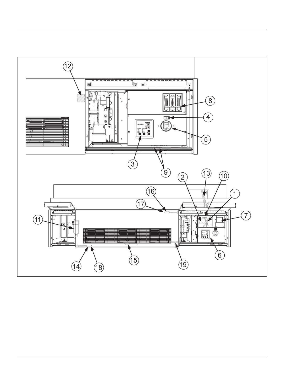
MicroTech II Sensors and Component Locations
Figure 23: MicroTech II Sensor and Component Locations
1. MicroTech II Unit Ventilator Controller (UVC):
(Located Beneath the Local User Interface Panel).
Factory mounted and run tested, microprocessorbased DDC control device capable of complete
Standalone unit control, Master/Servant control or
incorporated into a building-wide network using an
optional plug-in communication module. The UVC
contains a microprocessor that is preprogrammed
with the application code required to operate the
unit. The UVC supports up to 6 analog inputs,
12 binary inputs, and 9 binary outputs. The UVC
EXP I/O board supports up to 4 additional analog
AAF-HermanNelson Model AEQ Unit Ventilator 19
inputs and 8 additional binary outputs. Master/Ser-
vant units have the controller factory congured and
installed for a local peer-to-peer network between
these units (network wiring between these units
needs to be eld installed). Optional network communication is provided via plug-in communication
modules that connect directly to the UVC.
2. Communication Module (optional): Plug-in network communication module that is attached to the
UVC via a 12-pin header and 4 locking standoffs.
Available communication modules:
Page 20

MicroTech II Controls
• Building Automation and Control Network (BACnet®) Master Servant/Token Passing (MS/TP) Allows the UVC to inter-operate with systems that
use the BACnet (MS/TP) protocol with a conformance level of 3. Meets the requirements of ANSI/
ASHRAE 135-1995 standard for BACnet systems.
• LonWorks® compliant Space Comfort Controller
(SCC) – Supports the LonWorks SCC prole num-
ber 8500_10.
• Metasys N2® Open – Provides N2 Open network
communication capability to the UVC.
3. Local User Interface (LUI): The LUI provides a unit
mounted interface which indicates the current unit
operating state and can be used to adjust the unit
ventilator operating parameters (operating mode,
temperature set points, fan speed and occupancy
mode). The LUI features a 2-digit display, 7 keys (1
key is hidden), and 9 individual LED indicators. See
“Local User Interface” for further details.
4. Tenant Override Switch: Provides a momentary
contact closure that causes the unit to enter the
“tenant override” operating mode for a set time
period (default = 120 minutes).
5. Time Clock (TC) (optional on standalone units
only): Factory mounted 7 day/24 hour, digital time
clock with up to twenty (20) programs to sequence
the unit ventilator through occupied and unoccupied
modes in accordance with a user programmed time
schedule.
6. External Signal Connection Plugs: Three (3)
multi-pin plugs are factory provided and pre-wired
with short wire whips that are capped (they must
remain capped if not used).
Provided for eld wiring of :
• Remote Wall Mounted Temperature Sensor (op-
tional accessory).
• External Input Signals (by others): unoccupied,
remote shutdown, ventilation lockout, dew point/
humidity (night time operation), or exhaust interlock
signals
• External Output Options (by others): lights on/off,
fault indication signal, exhaust fan on/off or auxiliary
heat signal.
7. Motor Speed Transformer: (Located beneath the
Local User Interface Panel). Multi-tap auto-transformer provides multiple fan motor speed control
through the LUI.
8. Unit Main Power “On-Off” Switch (SW1): Disconnects the main power to the unit for servicing or
when the unit is to be shut down for an extended
period of time.
9. Fuse(s): Fan motor and controls have the hot
line(s) protected by factory installed cartridge type
fuse(s).
10. Control Transformer: 75 VA 24-volt NEC Class
2 transformer for 24 volt power supply. (Located
behind the motor transformer).
11. Outdoor Air/Return Air Damper Actuator (A1):
Direct coupled, oating point (tristate) actuator that
spring returns the outdoor air damper to the closed
position upon a loss of power.
12. Indoor, Direct Expansion (DX) Coil Refrigerant
Temperature Sensor – The sensor is installed on
the unit ventilator’s indoor refrigerant coil on the
right hand side of the coil “u-bend”. It is used to
sense low refrigerant temperatures on the indoor
coil.
13. Outdoor, Direct Expansion (DX) Coil Refrigerant Temperature Sensor - The sensor is installed
on the unit ventilator’s outdoor refrigerant coil on
the right hand side of the coil “u-bend”. It is used to
sense the refrigerant temperature on the outdoor
coil.
14. Room Temperature Sensor (S1): The unit mounted sensor is located in the sampling chamber (front,
center section) where room air is continuously
drawn through for prompt response to temperature
changes in the room. A Remote Wall Mounted
Temperature Sensor is also available for remote
room temperature sensing. (optional accessory).
15. Discharge Air Temperature Sensor (S2): The
sensor is located on the second fan from the right to
sense discharge air temperatures.
16. Outdoor Air Temperature Sensor (S3): The sensor is located in the outdoor air section of the unit
before the outdoor air damper. With network applications, the unit mounted sensor can be overridden
by a remote sensor through the network.
17. Outdoor Air Humidity Sensor (S8) (optional):
Unit mounted humidity sensor for units using
Expanded outdoor enthalpy economizer or Leading Edge indoor/outdoor, true enthalpy comparison
economizer. The sensor is located in the outdoor air
section of the unit before the outdoor air damper.
With network applications, the unit mounted sensor
can be overridden by a remote sensor through the
network.
20 AAF-HermanNelson Model AEQ Unit Ventilator
Page 21

MicroTech II Controls
18. Room Humidity Sensor (S6) (optional): Unit
mounted humidity sensor for units capable of active
dehumidication or with units using Leading Edge
indoor/outdoor, true enthalpy comparison economizer. The sensor is located in the sampling chamber (front, center panel) where room air is continuously drawn through for fast response to humidity
changes in the room. With network applications, the
unit mounted sensor can be overridden by a remote
sensor through the network.
19. CO2 Sensor (S7) (optional): Unit mounted, single
beam absorption infrared gas sensor with a sensing
range of 0 – 2000 ppm and voltage output of 0 to 10
VDC (100 ohm output impedance). The Pitot Tube
sensing device is located in the unit ventilator’s
return air stream. The optional CO2 sensor is used
with the UVC’s Demand Control Ventilation feature
to vary the amount of outside air based on actual
room occupancy. With network applications, the
unit mounted sensor can be overridden by a remote
sensor through the network.
Actuators
Outdoor Air/Return Air Damper (OAD) Actuator
The UVC is congured to operate a oating-point (tri-
state) direct-coupled actuator for the outdoor air damper. This actuator provides spring-return operation upon
loss of power for positive close-off of the outdoor air
damper. To determine damper position, the UVC uses
a separate, factory-preset, congurable setting for each
actuator's stroke time.
Figure 25: Outdoor Air Damper Actuator
AAF-HermanNelson Model AEQ Unit Ventilator 21
Page 22

Accessories
Optional Time Clock for Stand-Alone Units
As an option, stand-alone, non-servant unit ventilators
can be factory-equipped with a unit-mounted, digital,
24-hour/7-day time clock with 20 programs (Figure 27).
The clock is factory-wired to automatically place the
unit into occupied or unoccupied mode based upon its
schedule. Features of this clock include:
• Large keys with circular programming for easy
schedule setup
• An LCD display
• Manual 3-way override (On/Auto/Off)
• Capacitor backup to retain program memory during
power outages.
Figure 27: Optional Time Clock
ServiceTools™
ServiceTools for MicroTech II Unit Ventilators is a
CD containing software for operation on a personal
computer. This software provides a visual schematic of
the unit, a pictorial representation of the sequence of
operation and enables the service technician to:
• Monitor equipment operation.
• Congure network communications.
• Diagnose unit operating problems.
• Download application code and congure the unit.
This software is a purchased tool for service technicians
and will run on PCs with Windows® 98 (Second
Edition), 2000 (SP2), and NT4.0 (SP6) and XP (SP1)
operating systems. This tool is highly recommended
for startup and servicing. (It may be required for startup
and/or servicing, depending upon unit integration and
other requirements.) It has no BAS functions, such as
scheduling or trending, and it cannot serve as a Work
Station Monitoring package.
ServiceTools comes with a service cable having two
interface connections:
• A 12-pin connection to the main control board.
• A 3-pin connection to the optional communication
modules.
22 AAF-HermanNelson Model AEQ Unit Ventilator
Page 23

Accessories
Wall Louvers & Grilles
The 16-gauge QS 5052 mill nish aluminum louver
frame is divided in half horizontally, with make-up and
discharge-air stream sections to reduce air recirculation
within the vertical louver blade. The upper half of the
louver has a blockoff on the exterior side to increase
discharge air velocity and improve the throw of leaving
air.
The vertical louver can be ordered with anges that are
attached on the outside of all four sides of the louver,
resulting in a vertical dimension of 30" (762 mm). Weep
holes exist behind the bottom ange of the louver. A 1/2"
(13 mm) square aluminum wire mesh (bird screen) is
provided on the interior surface of the louver.
The vertical louver is fabricated from 20-gauge QS 5052
mill nish aluminum. The single piece blade has
Figure 28: Typical Wall Louver and Grille
Factory Mounted
Bird Screen
Fasteners
Bird Screen
Frame
Optional Flanges
Louver Blockoff
a turned edge along the entering and leaving surface
to reduce visibility of the outdoor coil and fan section,
and adds rigidity to the blade. The 72° offset bend near
the middle of the blade creates an air-path turn that
minimizes moisture carryover, with a total blade depth of
2¼" (57 mm) in direction of airow.
The louver is available in the following colors:
• Natural Aluminum nish (paintable QS 5052 Aluminum)
• Autumn Brown - thermosetting urethane powder
coat paint electrostatically applied and oven-cured
to provide correct chemical cross-linking.
• Dark Bronze - thermosetting urethane powder coat
paint electrostatically applied and oven-cured to
provide correct chemical cross-linking.
• Clear Anodized Aluminum nish
Figure 29: Vertical Blade Louver Outside View, Without
Flange
Outside View
Condenser
Discharge Air
Information Labels
Louver Blade
Bottom Flange
Detail of Notches (Drain Holes)
Mechanical Fasteners
(Number Required Varies
With Size of Louver)
Drain Notch At Bottom
Optional Factory
Mounted Exterior Grille
Condenser Inlet Air
Figure 30: Vertical Blade Louver Inside View, Without
Flange
Inside View
Condenser
Discharge Air
Condenser Inlet Air
Bird Screen
On Side
Toward Unit
Louver with weep holes
Bottom
AAF-HermanNelson Model AEQ Unit Ventilator 23
Page 24

Accessories
VentiMatic™ Shutter Room Exhaust
Ventilation
Outdoor air introduced by the unit ventilator must leave
the room in some way. In some states, exhaust vents
are required by law or code to accomplish this. The
VentiMatic Shutter is a more economical solution to the
problem.
• The VentiMatic shutter is a continuously variable,
gravity-actuated room exhaust vent (Figure 33).
It operates in direct response to positive static air
pressure created when ventilation air is brought
into the room by the unit ventilator. It is a “one-way”
shutter that opposes any ow of air into the room.
Figure 33: VentiMatic Shutter
Back (Outdoor Side) Front (Indoor Side)
The VentiMatic Shutter’s ability to exhaust only the
amount of air required results in considerable energy
savings. In the heating mode, the unit ventilator will
be able to bring in only the required percent minimum
outdoor air. Unlike systems that rely on powered
exhaust, no energy will be wasted heating excess
outdoor air. In the cooling mode, the unit ventilator will
be able to bring in 100% outdoor air for full natural or
free cooling when it is energy effective.
Since it is not powered, VentiMatic Shutter operation
is inherently silent. Unlike other non-powered vents, it
opens at an extremely low positive pressure (0.005").
Its shutter aps are made of temperature-resistant glass
fabric impregnated with silicone rubber for exibility and
long life. This fabric retains its original properties down
to -50°F.
VentiMatic Installation Considerations
Figure 34: VentiMatic Shutter Components
Louver ships assembled as one piece
The VentiMatic Shutter should be mounted on the same
wall as the unit ventilator. This neutralizes the effect of
wind pressure forcing excess air into the room through
the unit ventilator louver. That’s because the wind press
air ow that could occur with opposite-wall mounting.
The VentiMatic Shutter is generally mounted on an AAFHermanNelson wall louver (ordered separately) which
is then used for exhaust (Figure 34). For large unit
ventilators, two Ventimatic Shutters may be mounted
side by side on the same wall louver to adequately
promote exhaust air capacity. The size and appearance
of wall louvers and grilles used for unit ventilators and
for VentiMatic Shutters are identical and present an
architecturally coordinated and pleasing installation.
An ideal method of integrating the VentiMatic Shutter
with the unit ventilator is to locate the shutter behind
a matching open-shelf or closed-shelf storage cabinet mounted next to the unit ventilator. For example,
48-inch-length wall louver can be accommodated behind a 4-foot-high storage cabinet. The cabinet should
be ordered with a slotted-type kick plate to provide a
concealed exhaust air path to the shutter. This combina-
tion will enable a complete, integrated, energy-efcient
HVAC and room exhaust system
Note: Storage cabinets are provided by others. Contact
your McQuay sales representative for options.
24 AAF-HermanNelson Model AEQ Unit Ventilator
Page 25

Accessories
Figure 35: VentiMatic Shutter Installation
Louver
VentiMatic Shutter
Steel Shutter
Mounting Plate
The VentiMatic shutter assembly mounts on the same
wall as the unit ventilator
louver, to neutralize wind
effect.
Outside
Roomside
Building Wall
Closed Shelf Storage Cabinet
with Slotted Kickplate
Outside
Exhaust
Air
VentiMatic & Louver Assembly behind cabinet.
Flexible Glass Fabric,
Silicone-Impregnated
Shutter Leaf
Steel Bafe
Leaf Support
Cabinet Slotted Kickplate
AAF-HermanNelson Model AEQ Unit Ventilator 25
Page 26

Accessories
Storage Cabinets, Sink & Bubbler
Note: Storage Cabinets, Sink & Bubbler are provided by
others. Contact your McQuay sales representa-
tive for options.
AAF-HermanNelson storage cabinets are designed to
complement our classroom unit ventilators. They are
made from furniture-quality, cold-rolled steel and reinforced for additional strength to withstand the abuse of
a classroom environment. Cabinets are nished with a
durable epoxy powder coating to withstand marring and
scratches.
Storage Cabinets
Shelving cabinets feature epoxy powder coated steel
tops of charcoal bronze color or laminated tops.
• Available in 4 lengths: 24", 36", 48" and 60", in open
cabinets or with sliding doors with bottom glide track
for good alignment
• Optional door locks available
• 4 heavy-duty leveling legs that allow for 3/4" of verti-
cal adjustment
Sink & Bubbler Cabinet
Sink & bubbler cabinets have a one-piece 18-gauge
stainless steel top with a satin-brushed nish, a raised
front lip, and formed back and end splash boards.
• Available in 4 depths for model AEQ; 16-5/8", 195/8", 21-7/8" and 28"
• Underside of top is fully coated to minimize noise
and condensation
• Epoxy powder coated to match the Unit Ventilator
and other cabinets
• Bubbler Bowl provided as option
Figure 36: Typical Unit Ventilator Install with Storage
Cabinets Application
Self-Contained
Unit Ventilator
A Storage Cabinet, with doors
B Corner Filler Section
C Storage Cabinet with shelves, without doors
D Sink and Bubbler, with doors
E Utility Compartment
F 1" End Panel
26 AAF-HermanNelson Model AEQ Unit Ventilator
Page 27

Accessories
Utility Compartments
Note: Utility Compartments are provided by others.
Contact your McQuay sales representative for
options.
Utility Compartments can be used as spacing between
cabinets or walls and to provide added service access.
• Available in standard lengths of 18" and 24"
• Epoxy powder coated steel tops of Charcoal Bronze
paint or laminated top
Figure 37: Utility Compartment
1/4"- 20 × 1/2" Screws
1/4" Nuts
T extured Metal Top
Figure 38: 1" End Panel
16⅝" Unit
Projection
1/4"- 20 Tinnerman Nut, Clip
over Lower Hole in Unit Base
Figure 39: 6" End Panel
1/4"- 20 × 1/2" Screw
Tinnerman Nut,
Clip on End Panel
Steel Kickplate
1"
End
Panel
1/4"- 20 × 1/2"
Screw
1/4" Nuts
1/4"- 20 × 1/2" Screws
End Panels
One-inch end panels are typically used to nish off
stand-alone oor units (Figure 40). Six-inch end
panels with kick plates can be used to provide extra
space needed for piping (Figure 41). All end panels
are individually wrapped in plastic and boxed to help
prevent damage during construction.
16⅝" Unit
Projection
1/4"- 20 Tinnerman
Nut, Clip over Lower
Hole in Unit Corner
Bracket
1/4"- 20 × 1/2" Screw & 1/4" Flat Washer
Tinnerman Nut,
Clip on End Panel
Angle Bracket
Welded for
Rigidity
5"
End of Unit
Oxford Brown Kickplate, Factory Assembled
to Base of End Panel
Bracket
YC1934
6" End Panel
AAF-HermanNelson Model AEQ Unit Ventilator 27
Page 28

Application Considerations
Possible Heat Gain From
Why Classrooms Overheat
Overheated classrooms occur every day in schools
in every area of the country. The most serious result
is their detrimental effect on students’ ability to
concentrate and learn. Research has determined that
the ability to learn and retain knowledge decreases
rapidly as the temperature exceeds recommendations.
Overheated rooms also represent wasted fuel, resulting
in excessive operating costs.
Correcting an overheating problem in an existing
building is very difcult and expensive. It calls for
redesign and alteration of the heating and ventilating
system, necessitating considerable renovation. This
potential problem should be recognized, understood
and planned for when heating and ventilating systems
are designed for new and existing buildings.
Schools Have Special Needs
Schools have unique heating and ventilating needs,
in large part because of their variable occupancy and
usage patterns. Fewer cubic feet of space is provided
per student in a school building than in any other type
of commercial or public building. School classrooms
are typically occupied only six hours a day, ve days a
week, for only three-fourths of the year, with time out for
vacations. All in all, this represents approximately 15%
of the hours in a year that a classroom is occupied.
To understand the overheating problem in schools, one
must rst realize that the excess heat comes from what
is commonly termed “uncontrolled heat sources.” To
gain some perspective on how this affects heating and
cooling decisions, let’s take a look at a typical classroom
in the northern section of the midwestern United States.
Suppose we have a classroom that is 24 by 38 feet with
10-foot ceilings and 100 square feet of window area
along the outside wall. At an outside temperature of 0°F
and a desired room temperature of 72°F, let’s assume
the normal amount of heat loss from the room to the
outside is 55,000 BTUs per hour.
As the outside temperature changes, so does the
amount of heat that the room loses. This is represented
in Figure 40 by Room Heat Loss Line A, which
ranges from 55,000 BTU per hour at 0°F outside air
temperature to zero BTU at 70°F. Obviously, if the
Figure 40: Heat Gain vs. Heat Loss In Occupied
A
60,000
50,000
40,000
30,000
20,000
Room Heat Loss, BTU/HR
10,000
-10 010203040506070
ROOM HEAT LOSS LINES
B
C
D
Outside Air Temperature, °F
Temperature On Room
Heat Loss Line Above
Which Cooling Is
Always Required
10,000 BTU/HR
}
Sun, Direct & Reflected
8,500 BTU/HR
}
Heat Gain From Lights
7,800 BTU/HR
}
Heat Gain From
Students
Note: As this chart illustrates, even in very cold weather
an occupied classroom is more likely to require
cooling than heating.
Heat From Students
Body heat generated by students in a classroom is one
of the three primary sources of uncontrolled heat. In a
typical classroom of 30 students, the amount of heat
given off at all times will vary according to factors such
as age, activity, gender, etc. A conservative estimate is
260 BTU per hour per pupil. Multiply this by 30 and you
get a total of 7,800 BTU per hour added to the room by
the students alone. This excess heat is noted in Figure
40 as “Heat Gain from Students.”
Heat Gain From Lights
Heat emitted by the lighting system constitutes a
second uncontrolled heat source. Articial lighting
is needed in most classrooms even during daylight
hours to prevent unbalanced lighting and eye strain. A
typical classroom requires approximately 2,500 watts
of supplemental lighting to provide properly balanced
lighting. Fluorescent lights add heat to the room at the
rate of 3.4 BTU per watt per hour, or a total of 8,500
BTU per hour. This extra heat is represented in Figure
40 as “Heat Gain from Lights.”
Add the heat gain from lighting to the 7,800 BTU
introduced by student body heat and we now have
an extra 16,300 BTU/HR being introduced into
the classroom by uncontrolled sources. This heat
gain remains constant regardless of the outdoor air
temperature.
heating system were the only source of heat in the
classroom, the solution would be simple: The room
thermostat would cause the heating system to supply
exactly the amount of heat required to maintain the
room at the thermostat temperature setting. In reality,
the introduction of excess heat from a variety of
uncontrolled sources makes the challenge considerably
more complex.
28 AAF-HermanNelson Model AEQ Unit Ventilator
Solar Heat Gain
The sun is a third uncontrolled source of heat. And,
because it is neither positive nor constant, calculating
its contribution to the overall heat gain is difcult. Solar
heat gain can be the worst offender of the three in
classrooms with large windows. Indirect or reected
Page 29

Application Considerations
solar radiation is substantial even on cloudy days, even
in rooms with north exposure, as a result of what is
termed “skyshine.”
To get an idea of the potential effect of the sun, let’s
assume that the solar heat gain in our hypothetical
classroom will peak at 240 BTU/HR per square foot
of glass area. If we then assume a glass area of 100
square feet and at least 100 BTU/HR per square foot
of glass for solar heat gain, we can calculate a very
conservative estimate of 10,000 BTU/HR heat gain
through windows. If we add this to the heat from the
lights and body heat, total heat gain adds up to 26,300
BTU/HR from sources other than the heating and
ventilating system. This is indicated in Figure 40 by the
top horizontal line, which intersects Room Heat Loss
Line A at approximately 37°F. This is a reasonable
estimate of the maximum uncontrolled heat gain that
can be received in the typical classroom from these
common heat sources.
The Analysis
From Figure 40 it is evident that, at an outside
temperature of 48°F or higher, the heat given off by
30 students and classroom lighting is sufcient to
cause overheating. This is true even if the classroom is
occupied at night when solar heat gain is not a factor.
But, since classrooms are occupied during the day,
solar addition provides heat in varying amounts even
in classrooms with north exposures. Consequently, the
heating and ventilating system in our typical classroom
must provide cooling at all times when the outdoor
temperature is above 48°F and at any time during
colder weather when the solar heat gain exceeds room
heat loss.
If we assume an average winter temperature of
approximately 33°F in the region where our typical
classroom is located, we know that, half of the time,
both night and day, the outside temperature will be
above 33°F. However, since it is generally warmer
during the day, when school is in session, the heating
and ventilating system will be required to provide
cooling for this classroom during much of the time that
the room is occupied.
In this example, we’ve assumed that our classroom had
a room heat loss of 55,000 BTU/HR at a design outdoor
air temperature of 0°F (Room Heat Loss Line “A”).
Bear in mind, however, that the recent trend in “energy-
saving” building design often results in rooms with lower
room heat loss, as indicated by Room Heat Loss Lines
“B”, “C” and “D.” At 0°F design outdoor air temperature:
• Room “B” has a room heat loss of 45,000 BTU/HR
• Room “C” has a room heat loss of 35,000 BTU/HR
• Room “D” has a room heat loss of 25,000 BTU/HR
Note: The lowering of the temperature above which
cooling will always be required as the room heat
loss decreases.
We’ve noted that cooling is always required in
Classroom “A” when outdoor air temperatures exceed
48°F. In Classroom “B,” “C,” and “D” cooling is always
required when outdoor temperatures exceed 44°, 36°
and 23°F, respectively (Figure 40).
Now that we understand the reason for classrooms
overheating, the solution is simple: The heating and
ventilating system must provide cooling to take care of
the heat given off in the classroom by uncontrolled heat
sources.
Cooling The Classroom
The AAF-HermanNelson Unit Ventilator has become
a standard for heating and ventilating systems in
schools because it provides the solution for overheating
classrooms. The unit ventilator cools as well as heats.
During the heating season the outdoor air temperature
is nearly always below the desired room temperature.
It stands to reason then that the outside air should
be used to provide the cooling necessary to keep
classrooms down to thermostat temperature.
The classroom unit ventilator does just that. By
incorporating an automatically controlled outdoor air
damper, a variable quantity of outdoor air is introduced
in the classroom, metered exactly to counteract
overheating. Since our problem is more one of
cooling than of heating, it is evident that more than
just the room heat loss must be determined to design
a good heating and ventilating system. The cooling
requirements should be assessed as well, and the
free-cooling capacity of the equipment specied along
with the heating capacity required. If this is done, the
optimum learning temperature can be maintained in
each classroom.
AAF-HermanNelson Model AEQ Unit Ventilator 29
Page 30

Application Considerations
Meeting IAQ Requirements
Good indoor air quality (IAQ), which is important in the
home and at work, is no less important to students and
faculty in schools. For the past several years, efforts to
reduce energy costs in new school buildings have seen
the use of tighter construction, sealed windows and
heavier insulation. While these construction techniques
have helped reduce energy costs, tightly sealed
buildings, or envelopes, when combined with increased
use of recirculated air, can lead to unhealthy air.
For this reason, the American Society of Heating,
Refrigeration and Air Conditioning Engineers (ASHRAE)
now recommends 15 cfm of outdoor air per pupil, and
no longer endorses the practice of little or no usage of
outdoor air.
It should be kept in mind that a properly designed
exhaust system is essential for avoiding indoor air
quality problems. Simply put, if room air is not being
exhausted in a prescribed fashion, fresh outside air
cannot be introduced into the room. Likewise, an
excessive amount of outside air will be admitted,
wasting energy.
The AAF-HermanNelson Ventimatic shutter, a
gravity-actuated room exhaust vent, can solve both
these problems. The Ventimatic shutter allows the
correct amount of outdoor air to be brought into the
room while maintaining a slight positive pressure in
the room. This slight positive pressure, maintained
during normal operation, can also help prevent the
inltration of undesirable gases into the classroom. See
“VentiMatic™ Shutter Room Exhaust Ventilation” on
page 24.
Following ASHRAE Control Cycle II
ASHRAE Cycle II is a very economical sequence of
control because only minimum amounts of outdoor air
are heated and free outdoor air—natural cooling—is
available to offset the large internal heat gain associated
with the dense occupancy of classrooms.
AAF-HermanNelson unit ventilators are normally
controlled according to ASHRAE Control Cycle II.
ASHRAE control cycles apply only to heating, heatingand-ventilating and free-cooling operation. (For more
information on the ASHRAE Control Cycle II sequence,
see Figure 42 on page 33.)
Under ASHRAE Cycle II, the outdoor air damper
is closed during warmup of the room. As the room
temperature approaches the thermostat setting, the
outdoor air damper opens to a predetermined minimum
percentage of outside air. The heating coil capacity
controller then modulates to maintain the thermostat
setting.
If the room temperature rises above the thermostat
setting, the heating coil is turned off and the outdoor air
damper opens beyond the minimum position to maintain
the thermostat setting.
EXAMPLE: For a 60°F entering air mixture temperature
and 70°F room temperature, with 30°F outdoor
air temperature, 25% outdoor air will produce the
60°F mixture air temperature. When the outdoor air
temperature drops to 10°F, 12.5% outdoor air will
produce the 60°F mixture air temperature.
Night Setback
Substantial fuel savings can be realized by operating
the unit ventilator system at a reduced room setting at
night and during other unoccupied periods, such as
weekends and holidays. If the space temperature falls
below the setting of the unoccupied thermostat, the unit
fans will be brought on to provide additional heat. Units
with electric heat coils do not provide convective heat.
The electric coil and the unit fans will be brought on to
maintain the thermostat setting.
Typical Temperature Control Components
In general, unit ventilators require the following basic
DDC electrical components in order to operate on
any of the standard unit ventilator ASHRAE cycles of
control. The control components listed in this section
are for familiarization purposes only and should not be
construed as a bill of material.
Outdoor Air Damper Actuator
This is a modulating device under the control of the
room and discharge sensors. It positions the outdoor
air damper to admit the amount of outdoor air required
at any given point in the control cycle. The room
air damper is mechanically linked to the outdoor air
damper, which permits the use of a single actuator.
Electric actuators should be of the spring-return type so
that the outdoor air damper closes whenever the electric
power supply to the unit is interrupted.
Discharge Airstream Sensor
This device overrides the room sensor and modulates
the outdoor air damper toward the closed position when
the unit discharge air falls to a potentially uncomfortable
temperature.
30 AAF-HermanNelson Model AEQ Unit Ventilator
Page 31

Application Considerations
Electric Heat Step Control:
A modulating step controller, under control of the room
sensor, steps individual electric heating elements on
and off as required. Staging relays are sometimes used
in lieu of a step controller.
Additional Components
Additional components may be required depending on
the specic application. They include:
Room Temperature Sensor Chamber:
When the Room Temperature Sensor is to be mounted
within the unit ventilator rather than on the wall, it is
located behind a series of holes in the unit front panel
with the sensing element sealed within the room temperature chamber. The room temperature chamber is
a standard feature with units furnished with MicroTech
II controls. All units come with a factory mounted room
temperature sensor.
DX Cooling Low Ambient Lockout:
This lockout must be used on DX systems to lock out
the condensing unit when the outdoor air temperature
is below 64°F (17.5°C). This device must be integrated
into the control system so that the unit has full
ventilation cooling capability during the lockout period.
DX Low Temperature Limit:
This limit must be used on DX cooling units to deenergize the compressor when the refrigerant falls
below freezing. DX units with MicroTech II controls have
a factory-installed sensor on the return bend of the DX
coil that provides a sample of the coil’s temperature.
Two Stage Compressors
Our self-contained units with the two-stage compressor
will run on lower fan speeds up to 70% of the time,
improving comfort through better humidity control
and quieter operation, while minimizing issues with
over sizing. The unit is designed to operate in low
compression mode while in medium and low fan
speed. The reduced cooling capacity in the medium
and low fan speed will allow the system to run longer
at moderate and low load conditions providing better
humidity control. When the high capacity is needed
the high speed will provide high compression and full
capacity cooling.
Coil Selection
All coils have their own unshared n surfaces (some
manufacturers use a continuous n surface, sacricing
proper heat transfer). The result is maximum efciency
of heat transfer, which promotes comfort and reduces
operating costs.
An air break between coils in all AAF-HermanNelson
units is used to enhance decoupling of heat transfer
surfaces—providing full capacity output, comfort and
reduced operating costs.
Direct expansion (DX) coils are constructed of
aluminum ns with a formed, integral spacing collar. The
ns are mechanically bonded to the seamless copper
tubes by expansion of the tubes after assembly. Fins
are rippled or embossed for strength and increased heat
transfer surface.
Long Lasting Electric Heating Coils
With our draw-thru design, electric coils are directly
exposed to the air stream. They come with a built-in
switch to de-energize the coil when the center front
panel is removed. A unit-mounted disconnect switch is
included. A continuous electric sensory element for high
temperature is not required because the air is drawn
smoothly and evenly across the coils, prolonging life.
(Blow-thru designs use cal rods inserted into the tube of
a n tube coil that results in reduced heat transfer. The
constant movement of the electric heating cal rod within
the tube shortens life.)
Meeting AHRI 840 Requirements
AAF-HermanNelson unit ventilators are rated per AHRI
Standard 840. Per this standard, unit ventilators with
outside air ventilation and return air dampers must
provide ventilation air at a rate of minimum of 80%
rated standard air ow. They must also be capable
of providing any combination of humidity control,
circulation, heating or cooling, and ltering of air.
AAF-HermanNelson Model AEQ Unit Ventilator 31
Page 32

Application Considerations
Meeting IBC Seismic Requirements
AAF-HermanNelson unit ventilators can be specied,
as follows, to meet International Building Code seismic
requirements:
• All components included in these unit ventilators are
designed, manufactured and independently tested,
rated and certied to meet the seismic compliance
standards of the International Building Code.
• Components designated for use in systems that are
life safety, toxic, high hazard, combustible or am-
mable meet the on line, anchorage and load path
requirements for life safety as dened in IBC sections 1621.1.6, 1621.3.3,1707.7.2. and IBC Commentary, Volume II, section 1621.1.6, IBC notes
pertaining to the release of hazardous material.
• All components used as part of a system other than
the above meet as a minimum, all load path and
anchorage standards for components as outlined in
IBC section 1621.3.3 & 1707.7.2.
• All completed component assemblies are clearly
labeled for eld inspection. Seismic Compliance Labels include the manufacturer's identication, designation of certied models, denitive information
describing the product's compliance characteristics,
and the Independent Certifying Agency's name and
report identication.
Figure 41: Typical IBC Seismic Installation
Left End Compartment Area for Securing Unit
to Floor
In addition to all seismic requirements for IBC
Certication listed elsewhere in the project specication,
submittals for these units include:
1. A Certicate of Compliance from the Independent
Certifying Agency clearly indicating that components
supplied on this project are included in the compo-
nent manufacturer's Certicate of Compliance.
2. Clear installation instructions including all accessory
components that are part of the overall component
installation.
Typical Seismic Installation
When the unit is in the correct location, remove
the optional casters from the right and left end unit
compartments, and retain for later use. The bottom
plate cutouts, removed earlier to accomodate the caster
wheels, should be replaced.Using a 1/4" masonry bit,
drill through the unit bottom plate and into the oor
in the areas indicated in the gure at right (circled).
Determine the location of the holes based on clearance,
and the existence of the unit bottom plate, and as close
to the front edge of the unit as possible. Vacuum the
concrete dust that remains, so it is not drawn into the
unit components upon start up.
Using a power drill with a 5/16" hex socket bit,
secure the right and left ends of the unit with two (2)
(contractor supplied) 1/4" dia. x 2" x 5/16" hex washer
head masonry screws (or equivalent). Tighten the
screws down until the unit is secure to the oor, without
distorting the unit bottom plate.
Right End Compartment Area for Securing Unit to Floor
Right End - Optional Caster
Right End Compressor Compartment
1/4"dia. x 2" x 5/16" Hex Washer Head Concrete Screw – 2
32 AAF-HermanNelson Model AEQ Unit Ventilator
Page 33

Application Considerations
ASHRAE Cycle II
We strongly recommend that ASHRAE Cycle II be
implemented with all unit ventilators using controls
by others. ASHRAE Cycle II is a very economical
sequence since only the minimum amount of outside air
is conditioned and free natural cooling is available. See
Figure 42:
During warm-up (any classroom temperature 3°F or
more below heating setpoint), the outdoor air damper
is closed and the unit conditions only room air. As
room temperature approaches the heating setpoint the
outdoor air damper opens to a position that permits a
predetermined minimum amount of outside air to be
drawn in. Unit capacity is then controlled as needed
to maintain room setpoints. If room temperature rises
above room cooling setpoint, and the outside air is
adequate for economizer cooling, then the outdoor
air damper may open above the minimum position to
provide economizer cooling.
ASHRAE Cycle II requires that a minimum of three
temperature measurements be made:
Figure 42: ASHRAE Cycle II Operation
1 Classroom temperature.
2 Unit discharge air temperature.
3 Outdoor air temperature.
The control sequence should incorporate a Discharge
Air Low Limit function which requires a discharge
air temperature sensor and can override classroom
temperature control in order to maintain a discharge air
temperature setpoint of 55°F (ventilation cooling 45°F
mechanical cooling).
When the discharge air temperature drops below 55°F,
the discharge-air low-limit function will disable cooling
(if enabled) and modulate the unit’s heating capability
as needed to maintain the 55°F discharge-air setpoint
regardless of room temperature.
If the unit’s heating capability reaches 100%, then
the discharge air low-limit function will modulate the
outdoor air damper toward closed to maintain the 55°F
discharge air setpoint. Outdoor air temperature is used
to determine when to use economizer as a rst stage
of cooling, and when to use mechanical or hydronic
cooling as the rst stage of cooling.
Typical Outdoor Air Damper Operation
A Outdoor air damper closed.
B Outdoor air damper at minimum position.
C Economizer function is increasing the outdoor
air damper position.
Note: If outdoor air temperature is not adequate for
free cooling, secondary mechanical cooling
can be used in place of economizer cooling.
A low discharge air function is used to help
maintain comfort and provide additional equip-
ment protection by preventing the discharge
air from falling too low (typically 55°F), and
may force the outdoor air damper toward
closed to maintain the discharge air tempera-
ture regardless of room temperature.)
D Damper is at full open.
Typical Mechanical Heating Operation
E Heating (DX) is closed (or off).
F Heating begins to modulate (or on).
G Heating capability has reached 100%.
Typical Mechanical Cooling Operation
H Mechanical cooling (DX) is closed (or off).
J Mechanical cooling (DX) has reached 100%.
AAF-HermanNelson Model AEQ Unit Ventilator 33
Page 34

Application Considerations
Outside Air
Condenser Discharge
Condenser Supply Air
Unit Installation
Carefully arrange the location and installation of each
model AEQ unit to provide convenient service access
for maintenance and, if necessary, removal of the unit.
The installation consists of four basic elements in the
following order:
1. Louver
2. Galvanized Wall Sleeve
3. Horizontal Air Splitters by others (if required)
4. AEQ Self-contained Unit Ventilator
The louver brings in outdoor air for the condenser
fan section and ventilation air to the classroom while
providing a path for heated condenser air to exit.
The Wall Sleeve secures the unit, provides a watertight
and air tight seal to the building and brings in electrical
and control wiring (if required). It contains the unit main
power disconnect switch which is located in the wall
sleeve junction box. All eld electrical connections are
made inside this box.
Horizontal Air Splitters provide proper air paths and
minimize air recirculation.
The AEQ self-contained unit ventilator provides comfort
cooling and heating for the space. The Model AEQ unit
is designed to be installed into or up against an exterior
wall. The louver, air splitters (if required) and wall sleeve
are installed before the AEQ unit is installed.
On many jobs, the louver and wall sleeve are shipped
ahead of the unit itself. Installation instructions for these
components are shipped with the individual components
included in this publication.
The following are general instructions for suggested
applications. In all cases, good engineering practices
and local codes must be followed.
Lintels
When brickwork is built up to the top of the intake, lintels
must be used above the wall louvers. While the wall
is still wet, nish the brick on the top, bottom and both
sides of the intake opening with 1/2" cement mortar.
With the standard location of the wall louver, the bottom
of the intake opening must slope from the louver frame
up toward the intake opening to a point 1" above the
nished base of the unit.
If a metal sleeve connection is to be used between
the unit ventilator and the wall louver, this sleeve must
be installed after the unit ventilator is set, making a
weather-tight connection to the unit ventilator cabinet.
Turn the sleeve over the edge of the louver frame by
proper peening before the louver is nally installed.
Figure 43: Typical Self-Contained Unit Ventilator Installation
Internal Column for Wall
Bracing and Anchoring
(by others)
Optional Louver
Flange
Seal Horizontal Air
Splitters to Building
at Both Ends
Drain Holes in Splitters
(by others)
Louver–Bird Screen
3. Horizontal Air Splitters
(Field Made to Job Conditions by
Others) Pitch Down Toward Louver
Louver Blade
Weep Holes
Textured Charcoal Bronze Unit Projection Top
(Except Fully Recessed Wall Sleeve)
Conduit (by others)
Wall Sleeve Junction Box
Bottom Flange
1. Louver
Must be sealed watertight at top and both ends
Galvanized Condenser (Outdoor) Section
Textured, Scuff Resistant, Charcoal Bronze,
Environmentally Friendly Thermosetting Urethane
Powder Paint Top
4. AEQ Self-Contained Unit V entilator
Caster Kit for
Indoor Section (Optional)
Caster on
Outdoor Section
Wall Sleeve Threaded Studs for Fastening
to Unit (Ships on Wall Sleeve)
2. Galvanized Wall Sleeve
Sealed Cement Mortar, Pitched Away from Unit
Toward Louver
6" End Panel (Optional)
34 AAF-HermanNelson Model AEQ Unit Ventilator
Page 35

Application Considerations
Wall Louvers
The outdoor air wall louver is usually set directly back
of the unit ventilator. The position of the wall louver is
determined in general by the building construction. The
top of the lower channel of the louver frame should
be at least 1/2" below the level of the inlet to the unit
ventilator.
However, if a high intake opening is necessary, the top
of this opening should be not more than 28" above the
surface upon which the unit ventilator will set.
Louver (Note 2)
28"
(711mm)
Wall
Sleeve
28"
(711mm)
16-5/8"
(422mm)
3"
(76mm)
Figure 44: Wall Penetrations Detail
Louver (Note 2)
28"
(711mm)
Caulk
Perimeter
Louver (Note 2)
28"
(711mm)
Caulk
Perimeter
See
Note 1
Wall
Sleeve
Wall
Sleeve
Steel Lintel
(by others)
16-5/8"
(422mm)
3"
(76mm)
3" (76mm)
Full Recess
Steel Lintel
(by others)
16-5/8"
(422mm)
3"
(76mm)
3" (76mm)
Partial Recess
Notes:
1. Horizontal splitter (by others) must be installed
whenever there is any space between the wall
sleeve and the louver. It is necessary to seal the
ends of the wall opening.
2. The top and two sides of the louver must be
caulked water tight. The bottom edge of the lou-
ver must not be caulked, to allow for drainage.
3. Louvers may be recessed a maximum of 2"
(51mm) from the exterior face of the wall.
3" (76mm)
Caulk
Perimeter
No Recess
4. Drain must be ush with oor to allow unit instal-
lation and removal. Unit drain tube is 7/8" (22mm)
O.D. copper.
5. A eld-supplied air seal should be applied to the
exterior perimteter of the wall sleeve when unit is
installed with no recess.
Lintels
When brickwork is built up to the top of the intake, lintels
must be used above the wall louvers. While the wall
is still wet, nish the brick on the top, bottom and both
sides of the intake opening with 1/2" cement mortar.
With the standard location of the wall louver, the bottom
of the intake opening must slope from the louver frame
up toward the intake opening to a point 1" above the
nished base of the unit.
If a metal sleeve connection is to be used between
the unit ventilator and the wall louver, this sleeve must
be installed after the unit ventilator is set, making a
weather-tight connection to the unit ventilator cabinet.
Turn the sleeve over the edge of the louver frame by
proper peening before the louver is nally installed.
Figure 45: Typical Wall Opening with Lintels
Outdoor Side
Bottom of Intake
Opening Sloped
Down T oward Louver
Indoor Side
Top, Sides and Bottom on Inside of
Opening Finished Smooth with Mortar
Lintel (by others)
AAF-HermanNelson Model AEQ Unit Ventilator 35
Page 36

Application Considerations
Horizontal Splitters & Unit Recess Details
Horizontal splitter (by others) must be installed
whenever there is space between the wall sleeve and
the louver. Seal the ends of the wall opening to prevent
water penetration and air leakage. Pitch the splitters
toward the louver for water drainage
Figure 46: 16-5/8" Room Projection or Full Recess
16⅝" (422mm)
Room Projection
Inside T op
16⅝" (422mm)
28" (711mm)
Unit
30"
(762mm)
11½"
(292mm)
28"
(711mm)
(206mm)
4½" (102mm)
Louver
(See CAUTION)
8⅛"
1/2" (13mm)
W
Wall Thickness
S
1"
(25mm)
5/8"
(16mm)
11⅜"
(289mm)
Splitters
(by others)
Note: Shading indicates portion of unit wall sleeve
recessed into wall opening
Figure 47: 19-5/8" Room Projection
19⅝" (498mm)
W
Wall Thickness
Room Projection
Wall
Sleeve
Finish T op
Unit
Inside T op
Figure 48: 21-7/8" Room Projection
Room Projection
Wall
Sleeve
Finish T op
5¼"
(133mm)
28" (711mm)
21⅞" (557mm)
Unit
Inside T op
16⅝" (422mm)
11½"
(292mm)
28"
(711mm)
(206mm)
4½" (102mm)
Louver
(See CAUTION)
Wall Thickness
8⅛"
1/2" (13mm)
W
S
1"
(25mm)
5/8"
(16mm)
Splitters
(by others)
Note: Shading indicates portion of unit wall sleeve
recessed into wall opening
Figure 49: 28" Room Projection
W
Wall Sleeve
1"
28"
(711mm)
Wall Thickness
11½"
(292mm)
8⅛"
(206mm)
4½" (102mm)
S
(25mm)
5/8"
(16mm)
Room Projection
Finish T op
3
11
/8"
(289mm)
Splitters
(by others)
28" (711mm)
Unit Inside T op
16⅝" (422mm)
30"
(762mm)
30"
(762mm)
1/2" (13mm)
28" 21⅞" 19⅝" 16⅝"
Figure 49 Figure 48 Figure 47 Figure 46
28" (711mm)
8⅛"
1/2" (13mm)
S
1"
(25mm)
5/8"
(16mm)
3"
(76mm)
Splitters
(by others)
16⅝" (422mm)
28" (711mm)
11½"
(292mm)
28"
(711mm)
(206mm)
4½" (102mm)
Louver
(See CAUTION)
Note: Shading indicates portion of unit wall sleeve
recessed into wall opening
CAUTION
Horizontal splitter (by others) must be installed whenever there
is space between the wall sleeve and the louver. Seal the ends
of the wall opening to prevent water penetration and air leakage.
Pitch the splitters toward the louver for water drainage
30"
(762mm)
Louver
(See CAUTION)
Table 1: Wall Thickness, Unit Projection Into Room
Unit Projection into Room and Wall Sleeve Type
Wall
Thickness Louver
“W”
Splitter Length from Wall Sleeve to Louver "S"
2½" 2½" 0
4" 2½" 1½"
6" 2½" 3½"
8" 2½" 5½"
8⅝" 2½" 6⅛" 0"
10" 2½" 7½" 1⅜"
10⅞" 2½" 8⅜" 2¼" 0"
12" 2½" 9½" 3⅜" 1⅛"
13⅞" 2½" 3" 0"
14" 2½" 3⅛" 1/8"
16" 2½" 2⅛"
18" 2½" 4⅛"
24" 2½" 10⅛"
Note: All dimensions are approximate and subject to change
without notice. Actual building dimensions may vary.
36 AAF-HermanNelson Model AEQ Unit Ventilator
Page 37

Application Considerations
Interior Considerations
The interior wall surface behind the unit ventilator must
be smooth and level. A wall that is slightly out of plumb
can cause major problems with outside air leakage
into the room and unit. This could cause drafts and
potentially freeze coils.
Be certain that no gap is left between the unit and the
outside air louver opening. Otherwise, outside air can
leak into the room.
A rubberized, self-adhering membrane around the
outside air opening can be used to seal any air or water
leaks that might result from construction. Provide a seal
under the unit to prevent air inltration. In addition, seal
the unit top and side perimeters to prevent unnecessary
air inltration due to uneven walls.
Indoor Air Exhaust Considerations
All outdoor air introduced by the unit ventilator must
leave the room in some way. In some states, exhaust
Wall Sleeve Arrangements
vents are required by law. In states where vents are not
required by law, a decision must be made about how
best to handle this problem.
The venting system chosen should have the ability to
exhaust varying amounts of air equal to the amount
of outside air introduced by the oor unit ventilator. A
constant volume system, such as a powered exhaust, is
unable to respond to changing conditions. It will either
exhaust too much air, resulting in a negative pressure,
which draws in more outdoor air than desired. Or, it
will exhaust too little air, resulting in increased positive
pressure, which restricts the amount of outside air being
brought into the room.
The AAF-HermanNelson Ventimatic shutter is a more
economical solution to the problem. See “Ventimatic™
Shutter Room Exhaust Ventilation” on page 24 for
information on this system and its proper installation.
Figure 50: Recessed Wall Sleeve with Horizontal Air Splitters
By Others. Wall Sleeve must
be sealed watertight at top and
both ends at location shown.
Wall Sleeve
Splitter(s) Rail(s)
Seal Horizontal Air Splitter
Rail(s) to Louver. (By Others)
Indoor
By Others. Seal Horizontal Air Splitters to
building at both ends.
By Others. Seal both ends of
opening between Wall Sleeve
and Louver to prevent air and
water from entering building
structure and room.
Important Note:
By Others: Attach Horizontal Air Splitters
to Wall Sleeve Splitters as shown. Splitters to have 1" dia. drain hole approx.
6" from each end. Pitch splitters toward
louver for water drainage.
"D" Seal
By Others. Wall Sleeve
must be sealed watertight
at bottom at location shown.
Refer to cross section detail
of bottom of Wall Sleeve
and Louver.
By Others. Louver must be sealed air
and watertight at top and both ends.
Outside
3/16" Under Intake must be free for water run-off. Louver
intake must stand on embossed feet located on bottom.
By Others. Building must be sealed between Wall Sleeve and under
Louver for water run-off. Pitch toward Louver.
Condenser
Discharge
Condenser Inlet
Outdoor Air Inlet
AAF-HermanNelson Model AEQ Unit Ventilator 37
Page 38

Application Considerations
Figure 51: Sealing Full Projection Wall Sleeve and Horizontal Air Splitters
By Others. Apply sealant (by others) to bottom edge of unit (not shown)
and to top ange and both end anges of wall sleeve (as shown.) This must
provide a watertight seal to the wall of the building.
Seal Horizontal Air Splitter
Rail(s) to Louver. (By Others)
Indoor
Vertical and Horizontal
Mounting Bracket(s) Holes
for Non-Recessed (Full
Projection) Applications
Wall Sleeve
Splitter(s) Rail(s)
By Others. Louver must be sealed air
and watertight at top and both ends.
By Others. Seal Horizontal Air Splitters to
building at both ends.
By Others. Seal both ends of
opening between Wall Sleeve
and Louver to prevent air and
water from entering building
structure and room.
Important Note:
By Others: Attach Horizontal Air
Splitters to Wall Sleeve Splitters
as shown. Splitters to have 1" dia.
drain hole approx. 6" from each
end. Pitch splitters toward louver
for water drainage.
"D" Seal
By Others. Wall Sleeve must be
sealed air and watertight at bottom
“D” seal location shown. Refer to
cross section detail of bottom of
Wall Sleeve and Louver.
Figure 52: Attaching Splitters to Wall Sleeve Splitter Rails and Seals
Seals
Slope Down
Toward Louver
Screws (by others)
Top Splitter
(by others)
Outside
3/16" Under Intake must be free for water run-off. Louver
intake must stand on embossed feet located on bottom.
By Others. Building must be sealed between Wall Sleeve and under
Louver for water run-off. Pitch toward Louver.
1"(25mm)
Top Wall Sleeve Splitter Rail
Slope Down
Toward Louver
Bottom Splitter
(by others)
Seal
Seal
Bottom Wall Sleeve Splitter Rail
5/8"(16mm)
1"(25mm)
38 AAF-HermanNelson Model AEQ Unit Ventilator
Page 39

Application Considerations
Figure 53: Recessed Wall Sleeve - Direct Sealing Wall Sleeve to Louver
By Others. Wall Sleeve must be sealed watertight at
top and both ends at location shown.
Wall Sleeve Splitter Rail(s)
Indoor
By Others. Seal both ends of
opening between Wall Sleeve
and Louver to prevent air and
water from entering building
structure and room.
By Others. Wall Sleeve must be sealed air and
watertight at bottom at “D” seal location shown.
Refer to cross section detail of bottom of Wall
Sleeve and Louver.
"D" Seal
IMPORTANT NOTE: By Others. Seal Louver
to Wall Sleeve at top and bottom Wall Sleeve
Splitter Rails(s), and ends.
3/16" Under Intake must be free for water run-off. Louver intake must stand
on embossed feet located on bottom.
By Others. Building must be sealed between Wall Sleeve and under
Louver for water run-off. Pitch toward Louver.
By Others. Louver must be sealed air
and watertight at top and both ends.
Outside
Figure 54: Sealing Full Projection Wall Sleeve to Louver Intake Without Horizontal Air Splitters
By Others. Apply sealant (by others) to bottom edge of unit (not shown)
and to top ange and both end anges of wall sleeve (as shown.) This
must provide a watertight seal to the wall of the building.
Wall Sleeve
Indoor
Vertical and Horizontal Mounting
Bracket(s) Holes for Non-Recessed
(Full Projection) Applications
By Others. Seal both ends of opening between Wall Sleeve and Louver to prevent
air and water from entering the building
structure and room.
By Others. Wall Sleeve must be sealed air and watertight at bottom “D” seal at location shown.
Refer to cross section detail of bottom of Wall Sleeve and Louver.
Splitter Rail(s)
"D" Seal
IMPORTANT NOTE: By Others.
Seal Louver to Wall Sleeve at top,
Wall Sleeve Splitters and ends.
3/16" Under Intake must be free for water run-off. Louver intake
must stand on embossed feet located on bottom.
By Others. Building must be sealed between Wall Sleeve and
under Louver for water run-off. Pitch toward Louver.
By Others. Louver must be sealed
watertight at top and both ends.
Outside
AAF-HermanNelson Model AEQ Unit Ventilator 39
Page 40

Unit Selection
Quick Selection Procedure
The following procedure will provide you with a
rough determination of unit capacity for cooling and/
or heating based on the number of coil rows. Use
capacity tables for nal selection. Consult your local
AAF-HermanNelson representative for details on the
computer selection programs McQuay International
provides for this purpose
Cooling Performance Data – Size 024
Table 2: Standard Cooling at High Indoor Fan Speed
Conditions: Indoor 80°F db/67°F wb (27°C/19°C) Outdoor; 95°F db/75°F wb (35°C/24°C)
Total Capacity Sensible Capacity Efciency Power Nominal Air Flow
Btuh Watts Btuh Watts EER kW CFM L/S
21100 6180 15700 4530 9.1 2310 1000 472
Table 3: Partial Load Cooling at Medium Indoor Fan Speed
Conditions: Indoor 80°F db/67°F wb (27°C/19°C) Outdoor; 82°F db/65°F wb (28°C/18°C)
Total Capacity Sensible Capacity Efciency Power Nominal Air Flow
Btuh Watts Btuh Watts EER kW CFM L/S
16900 4950 12100 3540 11.6 1450 750 354
Table 4: Partial Load Cooling at Low Indoor Fan Speed
Conditions: Indoor 80°F db/67°F wb (27°C/19°C) Outdoor; 82°F db/65°F wb (28°C/18°C)
Total Capacity Sensible Capacity Efciency Power Nominal Air Flow
Btuh Watts Btuh Watts EER kW CFM L/S
16400 4800 11100 3240 11.7 1410 650 307
Heating Performance Data – Size 024
Table 5: Standard Heating at High Indoor Fan Speed
Conditions: Indoor 70°F db/60°F wb (21°C/16°C) Outdoor; 47°F db/42°F wb (8°C/6°C)
Total Capacity Efciency Power Nominal Air Flow
Btuh Watts COP Watts CFM L/S
20700 6090 3.0 2050 1000 472
Table 6: Partial Load Heating at Medium Indoor Fan Speed
Conditions: Indoor 70°F db/60°F wb (21°C/16°C) Outdoor; 62°F db/56.5°F wb (17°C/14°C)
Total Capacity Efciency Power Nominal Air Flow
Btuh Watts COP Watts CFM L/S
17700 5160 3.3 1560 750 354
Table 7: Partial Load Heating at Low Indoor Fan Speed
Conditions: Indoor 70°F db/60°F wb (21°C/16°C) Outdoor; 62°F db/56.5°F wb (17°C/14°C)
Total Capacity Efciency Power Nominal Air Flow
Btuh Watts COP Watts CFM L/S
17100 5010 3.1 1600 650 307
40 AAF-HermanNelson Model AEQ Unit Ventilator
Page 41

Unit Selection
Cooling Performance Data – Size 036
Table 8: Standard Cooling at High Indoor Fan Speed
Conditions: Indoor 80°F db/67°F wb (27°C/19°C) Outdoor; 95°F db/75°F wb (35°C/24°C)
Total Capacity Sensible Capacity Efciency Power Nominal Air Flow
Btuh Watts Btuh Watts EER kW CFM L/S
39300 11520 25500 7500 9.7 4065 1250 590
Table 9: Partial Load Cooling at Medium Indoor Fan Speed
Conditions: Indoor 80°F db/67°F wb (27°C/19°C) Outdoor; 82°F db/65°F wb (28°C/18°C)
Total Capacity Sensible Capacity Efciency Power Nominal Air Flow
Btuh Watts Btuh Watts EER kW CFM L/S
30800 9030 2000 5850 11.7 2630 1000 472
Table 10: Partial Load Cooling at Low Indoor Fan Speed
Conditions: Indoor 80°F db/67°F wb (27°C/19°C) Outdoor; 82°F db/65°F wb (28°C/18°C)
Total Capacity Sensible Capacity Efciency Power Nominal Air Flow
Btuh Watts Btuh Watts EER kW CFM L/S
29400 8610 18000 5280 11.4 2580 800 378
Heating Performance Data – Size 036
Table 11: Standard Heating at High Indoor Fan Speed
Conditions: Indoor 70°F db/60°F wb (21°C/16°C) Outdoor; 47°F db/42°F wb (8°C/6°C)
Total Capacity Efciency Power Nominal Air Flow
Btuh Watts COP Watts CFM L/S
35000 10230 2.6 3910 1250 590
Table 12: Partial Load Heating at Medium Indoor Fan Speed
Conditions: Indoor 70°F db/60°F wb (21°C/16°C) Outdoor; 62°F db/56.5°F wb (17°C/14°C)
Total Capacity Efciency Power Nominal Air Flow
Btuh Watts COP Watts CFM L/S
29100 8520 2.8 3055 1000 472
Table 13: Partial Load Heating at Low Indoor Fan Speed
Conditions: Indoor 70°F db/60°F wb (21°C/16°C) Outdoor; 62°F db/56.5°F wb (17°C/14°C)
Total Capacity Efciency Power Nominal Air Flow
Btuh Watts COP Watts CFM L/S
28000 8220 2.6 3180 800 378
Note: AEQ sizes 036, 044, & 054, manufactured for replacement applications only, not to be installed in new
construction projects in accordance with ASHRAE 90.1.
AAF-HermanNelson Model AEQ Unit Ventilator 41
Page 42

Unit Selection
Cooling Performance Data – Size 044
Table 14: Standard Cooling at High Indoor Fan Speed
Conditions: Indoor 80°F db/67°F wb (27°C/19°C) Outdoor; 95°F db/75°F wb (35°C/24°C)
Total Capacity Sensible Capacity Efciency Power Nominal Air Flow
Btuh Watts Btuh Watts EER kW CFM L/S
43700 12810 30000 8790 9.1 4790 1500 708
Table 15: Partial Load Cooling at Medium Indoor Fan Speed
Conditions: Indoor 80°F db/67°F wb (27°C/19°C) Outdoor; 82°F db/65°F wb (28°C/18°C)
Total Capacity Sensible Capacity Efciency Power Nominal Air Flow
Btuh Watts Btuh Watts EER kW CFM L/S
35500 10410 23800 6990 11.8 3010 1150 542
Table 16: Partial Load Cooling at Low Indoor Fan Speed
Conditions: Indoor 80°F db/67°F wb (27°C/19°C) Outdoor; 82°F db/65°F wb (28°C/18°C)
Total Capacity Sensible Capacity Efciency Power Nominal Air Flow
Btuh Watts Btuh Watts EER kW CFM L/S
34300 10050 22000 6420 11.6 2955 950 448
Heating Performance Data – Size 044
Table 17: Standard Heating at High Indoor Fan Speed
Conditions: Indoor 70°F db/60°F wb (21°C/16°C) Outdoor; 47°F db/42°F wb (8°C/6°C)
Total Capacity Efciency Power Nominal Air Flow
Btuh Watts COP Watts CFM L/S
41600 12180 2.6 4620 1500 708
Table 18: Partial Load Heating at Medium Indoor Fan Speed
Conditions: Indoor 70°F db/60°F wb (21°C/16°C) Outdoor; 62°F db/56.5°F wb (17°C/14°C)
Total Capacity Efciency Power Nominal Air Flow
Btuh Watts COP Watts CFM L/S
36100 10560 3.0 3525 1150 542
Table 19: Partial Load Heating at Low Indoor Fan Speed
Conditions: Indoor 70°F db/60°F wb (21°C/16°C) Outdoor; 62°F db/56.5°F wb (17°C/14°C)
Total Capacity Efciency Power Nominal Air Flow
Btuh Watts COP Watts CFM L/S
35400 10380 2.9 3625 950 448
Note: AEQ sizes 036, 044, & 054, manufactured for replacement applications only, not to be installed in new
construction projects in accordance with ASHRAE 90.1.
42 AAF-HermanNelson Model AEQ Unit Ventilator
Page 43

Unit Selection
Cooling Performance Data – Size 054
Table 20: Standard Cooling at High Indoor Fan Speed
Conditions: Indoor 80°F db/67°F wb (27°C/19°C) Outdoor; 95°F db/75°F wb (35°C/24°C)
Total Capacity Sensible Capacity Efciency Power Nominal Air Flow
Btuh Watts Btuh Watts EER kW CFM L/S
51200 15000 34400 10080 9.1 5620 1500 708
Table 21: Partial Load Cooling at Medium Indoor Fan Speed
Conditions: Indoor 80°F db/67°F wb (27°C/19°C) Outdoor; 82°F db/65°F wb (28°C/18°C)
Total Capacity Sensible Capacity Efciency Power Nominal Air Flow
Btuh Watts Btuh Watts EER kW CFM L/S
41600 12180 26600 7770 11.5 3620 1150 542
Table 22: Partial Load Cooling at Low Indoor Fan Speed
Conditions: Indoor 80°F db/67°F wb (27°C/19°C) Outdoor; 82°F db/65°F wb (28°C/18°C)
Total Capacity Sensible Capacity Efciency Power Nominal Air Flow
Btuh Watts Btuh Watts EER kW CFM L/S
40000 11730 24500 7170 11.2 3570 950 448
Heating Performance Data – Size 054
Table 23: Standard Heating at High Indoor Fan Speed
Conditions: Indoor 70°F db/60°F wb (21°C/16°C) Outdoor; 47°F db/42°F wb (8°C/6°C)
Total Capacity Efciency Power Nominal Air Flow
Btuh Watts COP Watts CFM L/S
49700 14580 2.5 5820 1500 708
Table 24: Partial Load Heating at Medium Indoor Fan Speed
Conditions: Indoor 70°F db/60°F wb (21°C/16°C) Outdoor; 62°F db/56.5°F wb (17°C/14°C)
Total Capacity Efciency Power Nominal Air Flow
Btuh Watts COP Watts CFM L/S
43000 12600 2.8 4500 1150 542
Table 25: Partial Load Heating at Low Indoor Fan Speed
Conditions: Indoor 70°F db/60°F wb (21°C/16°C) Outdoor; 62°F db/56.5°F wb (17°C/14°C)
Total Capacity Efciency Power Nominal Air Flow
Btuh Watts COP Watts CFM L/S
42300 12390 2.6 4720 950 448
Note: AEQ sizes 036, 044, & 054, manufactured for replacement applications only, not to be installed in new
construction projects in accordance with ASHRAE 90.1.
AAF-HermanNelson Model AEQ Unit Ventilator 43
Page 44

Unit Selection
Selection Procedure
Step 1: Determine Design Conditions
Determine design indoor and outdoor air temperatures
in accordance with established engineering practices,
as outlined in the ASHRAE Guide or other authoritative
source. Indoor temperatures of 80°F dry bulb, 67°F wet
bulb for summer and 70°F dry bulb for winter usually
are acceptable for design or peak load conditions, even
though the expected operating conditions of the system
may be somewhat different.
Step 2: Determine Heating and Cooling
Loads
Calculate design winter heating losses and summer
cooling loads in accordance with the procedures
outlined by the ASHRAE Guide or other authoritative
source. Perhaps the greatest consideration in
calculating design loads is solar heat gain. August solar
heat values might be used for summer cooling loads,
but should not be used for ventilation air or “natural
cooling” capacity calculations; since these cooling loads
reach their maximum in the spring and autumn months.
The natural cooling capacity is usually calculated for 55°
or 60°F outdoor air temperature.
Equation 7: CFM Based On Sensible Cooling Load
1.086 x TD
Q sensible (space)
CFM =
Q sensible is the maximum sensible room load and T.D.
is the temperature difference between the room design
dry bulb temperature and the nal or leaving-air dry bulb
temperature. For these calculations, a T.D. of 20°F is
usually assumed to be desirable to avoid delivering air
too cold for comfort. This gure may be varied one or
two degrees for reasons of practicality.
Note: The sensible load used in the preceding equation
is the space load and excludes the ventilation
load.
Most areas have ventilation codes which govern
the amount of ventilation air required for school
applications. For other than school applications or areas
not having codes, the ASHRAE Guide may be used for
authoritative recommendations and discussion of the
relation between odor control and outdoor air quantities.
The minimum outdoor air quantity recommended
by ASHRAE is 15 CFM per person. Lower percent
minimum outdoor air settings are more economical. In
the interest of economy, it may be desirable to use lower
percent minimums if there are no ventilation codes.
Step 3: Determine Air Quantity Required
Air quantity for heating applications is determined from
circulation of a denite number of room air volumes per
hour. Table 26 gives the recommended number of room
air changes per hour.
Table 26: Recommended Room Air Changes Per Hour
Type of Space
Classrooms, Ofces 6 to 9
Laboratories, Shops 6 to 8
Cafeterias & Kitchens 4-1/2 to 7
For rooms facing east, south or west, the higher
values shown in the table should be used so adequate
ventilation cooling will be available to prevent
overheating during mild sunny weather. The following
equation is helpful to determine the CFM air delivery for
any given rate of circulation:
Equation 6: CFM For Given Rate Of Circulation
Room Volume (cu ft) × Room Changes per Hour
60
In mechanical cooling applications, the total air quantity
may be determined or veried by use of the sensible
cooling load equation:
Recommended number of
room air changes per Hour
= CFM
Step 4: Select Unit Size
The unit should be selected to meet or exceed the CFM
delivery requirement previously determined. All model
types are available with nominal capacities of 1000,
1250 and 1500 CFM. Unit sizes 024, 036, 044 and 054.
Heating Capacity
Unit heating capacity should be selected to equal or
slightly exceed the computed room heat loss. The
heating required to warm the outdoor ventilating air up
to room temperature must also be calculated.
Cooling Capacity
Unit cooling capacity should be selected to equal or
slightly exceed the sum of computed room sensible
and latent heat gains (Room Total Capacity). When
operating on the mechanical cooling cycle, the control
system introduces a constant amount of outdoor air for
ventilation. The latent and sensible heat gain from this
outdoor ventilation air must be added to the room total
cooling load before choosing the proper capacity unit.
44 AAF-HermanNelson Model AEQ Unit Ventilator
Page 45
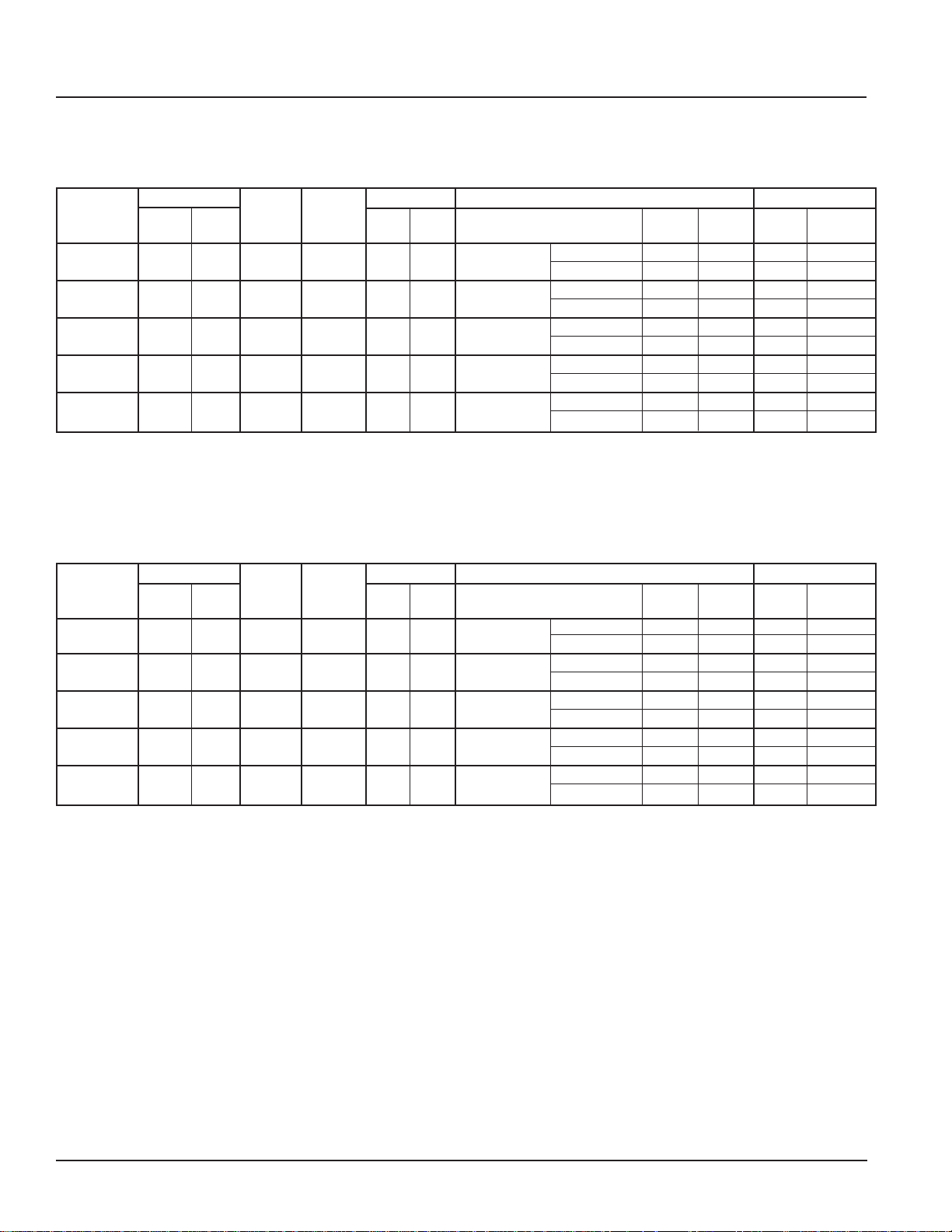
Unit Selection
Engineering Data
Table 27: Model AEQ Electrical Data – Size 024
Voltage Range
Voltage
208/60/1 197 228 2.7 2.9 11.4 52.0
High (6-elem.) 16.0 76.9 116.0 125
230/60/1
High (6-elem.) 15.3 66.7 103.2 110
208/60/3
High (6-elem.) 16.0 44.4 71.0 80
230/60/3
High (6-elem.) 15.3 38.5 63.6 70
460/60/3
Min. Max.
207 253 2.7 2.9 11.4 52.0
197 228 2.7 2.9 7.9 59.0
207 253 2.7 2.9 7.9 59.0
414 506 2.7 1.2 3.9 29.7
Room Outdoor
Fan Fan Heater Heater Maximum
FLA FLA
High (6-elem.) 15.3 19.2 32.8 35
Notes:
1
Electric Heat Options are with Compressor and Outdoor Fan
FLA = Full Load Amps RLA = Rated Load Amps MCA = Minimum Circuit Ampacity
LRA = Locked Rotor Amps
Compressor Heating Options Power Supply
RLA LRA Heat Type
1
Electric Heat
1
Electric Heat
1
Electric Heat
1
Electric Heat
1
Electric Heat
Low (3-elem.) 8.0 38.5 67.9 70
Low (3-elem.) 7.7 33.3 61.5 70
Low (3-elem.) 8.0 22.2 43.2 45
Low (3-elem.) 7.7 19.2 39.5 40
Low (3-elem.) 7.7 9.6 20.8 20
kW Amps
MCA
Fuse
Table 28: Model AEQ Electrical Data – Size 036
Voltage Range
High (6-elem.) 20.0 96.2 152.9 150
High (6-elem.) 19.2 83.3 136.9 150
High (6-elem.) 20.0 55.5 97.6 100
High (6-elem.) 19.2 48.1 88.4 90
Voltage
208/60/1
230/60/1
208/60/3
230/60/3
460/60/3
Min.
Max.
197 228 2.7 6.8 18.6 96.0
207 253 2.7 6.8 18.6 96.0
197 228 2.7 6.8 15.0 88.0
207 253 2.7 6.8 15.0 88.0
414 506 2.7 2.2 6.8 44.0
Room Outdoor
Fan
FLA
High (6-elem.) 19.2 24.1 43.5 45
Notes:
1
Electric Heat Options are with Compressor and Outdoor Fan
FLA = Full Load Amps RLA = Rated Load Amps MCA = Minimum Circuit Ampacity
LRA = Locked Rotor Amps
Compressor Heating Options Power Supply
Fan
FLA
RLA LRA
1
Electric Heat
1
Electric Heat
1
Electric Heat
1
Electric Heat
1
Electric Heat
Heat Type
Heater Heater Maximum
Low (3-elem.) 10.0 48.1 92.8 90
Low (3-elem.) 9.6 41.7 84.8 90
Low (3-elem.) 10.0 27.8 62.9 70
Low (3-elem.) 9.6 24.1 58.3 60
Low (3-elem.) 9.6 12.0 28.4 30
kW Amps
MCA
Fuse
AAF-HermanNelson Model AEQ Unit Ventilator 45
Page 46

Unit Selection
Engineering Data
Table 29: Model AEQ Electrical Data – Size 044
Voltage Range
High (6-elem.) 24.0 115.4 183.2 200
High (6-elem.) 23.0 100.0 164.0 175
High (6-elem.) 24.0 66.6 111.5 110
High (6-elem.) 23.0 57.7 100.4 100
Voltage
208/60/1
230/60/1
208/60/3
230/60/3
460/60/3
Min. Max.
197 228 2.7 6.8 23.6 96.0
207 253 2.7 6.8 23.6 96.0
197 228 2.7 6.8 15.0 88.0
207 253 2.7 6.8 15.0 88.0
414 506 2.7 2.2 7.1 41.0
Room Outdoor
Fan Fan Heater Heater Maximum
FLA
High (6-elem.) 23.0 28.9 49.9 50
Notes:
1
Electric Heat Options are with Compressor and Outdoor Fan
FLA = Full Load Amps RLA = Rated Load Amps MCA = Minimum Circuit Ampacity
LRA = Locked Rotor Amps
Compressor Heating Options Power Supply
FLA
RLA LRA
Heat Type
1
Electric Heat
1
Electric Heat
1
Electric Heat
1
Electric Heat
1
Electric Heat
Low (3-elem.) 12.0 57.7 111.1 125
Low (3-elem.) 11.5 50.0 101.5 110
Low (3-elem.) 12.0 33.3 69.9 70
Low (3-elem.) 11.5 28.9 64.3 70
Low (3-elem.) 11.5 14.4 31.8 35
kW Amps
MCA
Fuse
Table 30: Model AEQ Electrical Data – Size 054
Voltage Range
High (6-elem.) 24.0 115.4 189.5 200
High (6-elem.) 23.0 100.0 170.3 175
High (6-elem.) 24.0 66.6 117.3 125
High (6-elem.) 23.0 57.7 106.2 110
460/60/3
Voltage
208/60/1
230/60/1
208/60/3
230/60/3
Min. Max.
197 228 2.7 6.8 28.6 118.0
207 253 2.7 6.8 28.6 118.0
197 228 2.7 6.8 19.6 123.0
207 253 2.7 6.8 19.6 123.0
414 506 2.7 2.2 10.0 62.0
Room Outdoor
Fan Fan Heater Heater Maximum
FLA FLA
High (6-elem.) 23.0 28.9 53.5 60
Notes:
1
Electric Heat Options are with Compressor and Outdoor Fan
FLA = Full Load Amps RLA = Rated Load Amps MCA = Minimum Circuit Ampacity
LRA = Locked Rotor Amps
Table 31: General Unit Data
Model AEQ 024 036 044 054
Nominal Airow – CFM (L/S) 1000 (472) 1250 (590) 1500 (708) 1500 (708)
Width - In. (MM) 8.25 (210) 8.25 (210) 8.25 (210) 8.25 (210)
Room Fan Motor Horse Power 1/4
Outdoor Fan Motor Horse Power 1/3
Nom. Size – In. (MM) 10 × 48½ × 1 (254 × 1232 × 25) 10 x 60½
Filter Data Area – FT
Quantity 1 1 2 2
Approx. Ship Weight – Lbs. (KG) 885 (402) 975 (442) 1075 (448) 1075 (448)
No. of Fans 3 4 4 4
Room
Fan Data
Dia. – In. (MM) 8.12
2
(M2) 3.37 (0.31) 4.20 (0.39) 5.08 (0.47) 5.08 (0.47)
Compressor Heating Options Power Supply
RLA LRA
(206) 8.12 (206)
1
Electric Heat
1
Electric Heat
1
Electric Heat
1
Electric Heat
1
Electric Heat
Heat Type
kW Amps
MCA
Low (3-elem.) 12.0 57.7 117.4 125
Low (3-elem.) 11.5 50.0 107.8 110
Low (3-elem.) 12.0 33.3 75.6 80
Low (3-elem.) 11.5 28.9 70.1 80
Low (3-elem.) 11.5 14.4 35.4 40
1/4
3/4
× 1 (254 × 1537 × 25) 10 × 36½ × 1 (254 × 927 × 25)
8.12 (206)
1/4
3/4
8.12 (206)
1/4
3/4
Fuse
46 AAF-HermanNelson Model AEQ Unit Ventilator
Page 47

Details & Dimensions
Figure 55: Unit Size 024 Dimensions
AAF-HermanNelson Model AEQ Unit Ventilator 47
Page 48

Details & Dimensions
Figure 56: Model AEQ, Unit Size 036 Dimensions
48 AAF-HermanNelson Model AEQ Unit Ventilator
Page 49

Details & Dimensions
Figure 57: Model AEQ, Unit Size 044 & 054 Dimensions
AAF-HermanNelson Model AEQ Unit Ventilator 49
Page 50

Details & Dimensions
27 7/8"
(708mm)
27
7
/8"
(708mm)
7"
(178mm)
2
1
/2"
(64mm)
1"
(25mm)
27
7
/8"
(708mm)
18"
(457mm)
4"
(102mm)
1"
(25mm)
27
7
/8"
(708mm)
22"
(559mm)
4"
(102mm)
1"
(25mm)
16 5/8"
(422mm)
1"
(25mm)
27 7/8"
(708mm)
28"
(711mm)
1"
(25mm)
27
7
/8"
(708mm)
22"
(559mm)
4"(102mm)
1"
(25mm)
27
7
/8"
(708mm)
27
7
/8"
(708mm)
7"
(178mm)
2
1
/2"(64mm)
1"
(25mm)
27
7
/8"
(708mm)
22"
(559mm)
4"
(102mm)
1"
(25mm)
27
7
/8"
(708mm)
18"
(457mm)
4"
(102mm)
1"
(25mm)
27
7
/8"
(708mm)
27
7
/8"
(708mm)
7"
(178mm)
2
1
/2"(64mm)
1"
(25mm)
27
7
/8"
(708mm)
22"
(559mm)
4"(102mm)
1"
(25mm)
27
7
/8"
(708mm)
18"
(457mm)
4"
(102mm)
1"
(25mm)
19
5
/
8
"
(498mm)
1"
(25mm)
21
7
/
8
"
(556mm)
1"
(25mm)
27 7/8"
(708mm)
27
7
/8"
(708mm)
7"
(178mm)
2
1
/2"
(64mm)
1"
(25mm)
27
7
/8"
(708mm)
18"
(457mm)
4"
(102mm)
1"
(25mm)
27
7
/8"
(708mm)
22"
(559mm)
4"
(102mm)
1"
(25mm)
16 5/8"
(422mm)
1"
(25mm)
27 7/8"
(708mm)
28"
(711mm)
1"
(25mm)
27
7
/8"
(708mm)
22"
(559mm)
4"(102mm)
1"
(25mm)
27
7
/8"
(708mm)
27
7
/8"
(708mm)
7"
(178mm)
2
1
/2"(64mm)
1"
(25mm)
27
7
/8"
(708mm)
22"
(559mm)
4"
(102mm)
1"
(25mm)
27
7
/8"
(708mm)
18"
(457mm)
4"
(102mm)
1"
(25mm)
27
7
/8"
(708mm)
27
7
/8"
(708mm)
7"
(178mm)
2
1
/2"(64mm)
1"
(25mm)
27
7
/8"
(708mm)
22"
(559mm)
4"(102mm)
1"
(25mm)
27
7
/8"
(708mm)
18"
(457mm)
4"
(102mm)
1"
(25mm)
19
5
/
8
"
(498mm)
1"
(25mm)
21
7
/
8
"
(556mm)
1"
(25mm)
16 5/8"
(422mm)
6"
(152mm)
28"
(711mm)
19 5/8"
(498mm)
21
7
/8"
(556mm)
6"
(152mm)
6"
(152mm)
6"
(152mm)
27"
(686mm)
3"
(76mm)
27"
(686mm)
3"
(76mm)
27"
(686mm)
3"
(76mm)
27"
(686mm)
3"
(76mm)
End Panels
Figure 58: 1" (25mm) and 6" (152mm) End Panel Dimensions – Self-Contained Floor Unit Ventilators
All Dim.
in Inches
Top View
165/8" (422mm) Deep
End Panels
5
/8" (498mm) Deep
19
End Panels
217/8" (556mm) Deep
End Panels
28" (711mm) Deep
End Panels
End View
With No
Cut-out
End View
with 2
1
/2"
x 7"
(64mm x
178mm)
Cut-out
End View
with 4" x 18"
(102mm x
Dashed lines indicate kickplate
457mm)
Cut-out
End View
with 4" x 22"
(102mm x
559mm)
Cut-out
6" (152mm) End Panel Dimensions – Self-Contained Floor Unit Ventilator
Top View
End View
With No
Cut-out
50 AAF-HermanNelson Model AEQ Unit Ventilator
Page 51

Details & Dimensions
+
++
+
+
+
+
+
+
+
+
+
+
+
W (see Table)
2
1
/2"
(63.5 mm)
14±
1
/8"
(356±3.2mm)
28"
(711 mm)
1 1/4"
(31.8 mm)
Optional Flange
7
/8"
(22.2 mm)
A (see Table)
Wall Intake Louvers & Grilles
Louvers are available with a vertical blade
conguration, constructed of heavy-gauge (unpainted,
painted, or clear anodized) aluminum.
• The louver is divided in half horizontally to prevent
condenser air recirculation.
• A bird screen is provided on the leaving air side of
the intake louver.
• Louvers can be supplied with or without anges:
• Flanged louvers are typically used for a panel wall
nish.
• Unanged louvers are typically used for recessing
into a masonry wall.
• An optional (factory-mounted) heavy-duty lattice exterior grille is available with horizontal and vertical
lines that “line up” with the louver blades to present
an aesthetic appearance.
• Louvers are available in both horizontal and vertical
blade congurations:
Figure 59. Typical Wall Louver and Grille
Factory Mounted
Bird Screen
Fasteners
Bird Screen
Frame
Optional Flanges
Splitter Lines Up With
Wall Sleeve Splitter
Figure 60: Grille Detail
Table 32: Wall Louver Dimensions (W)
Unit Size
024 28" × 84" 711 × 2134 9" 229
036 28" × 96" 711 × 2438 9" 229
044, 054 28" × 108" 711 × 2743 7" 178
Louver (H × W) Discharge Air (A)
Size (H × W) MM Opening (A) MM
Figure 61: Vertical Blade Louver, Without Flange
Outside View
Condenser
Discharge Air
Condenser Inlet Air
Information Labels
Louver Blade
Optional Factory
Mounted Exterior Grille
Figure 62: Vertical Blade Louver, Without Flange
Inside View
Mechanical Fasteners
(Number Required Varies
With Size of Louver)
Drain Notch At Bottom
Bottom Flange
Detail of Notches (Drain Holes)
Bird Screen
On Side Toward Unit
AAF-HermanNelson Model AEQ Unit Ventilator 51
Condenser
Discharge Air
Condenser Inlet Air
Louver with weep holes
Page 52

Details & Dimensions
V entiMatic Shutter Assembly
Notes:
1. Horizontal blade louver shown. Vertical blade louver
also available with Ventimatic shutter.
2. Optional exterior grille matches unit ventilator louver
in material and design. Mounted in wall louver.
Figure 63: VenitMatic Shutter Assembly with Optional Grille
Two Shutter Assemblies
Mounted on One Louver
B
(See table)
3. Optional interior grille mounting hardware is not
included.
4. Louver leaves seal against plate to prevent air
inltration.
Aluminum Exterior Grille (optional)
A
(See table)
B
(See table)
Aluminum Louver
Bafe Plate
C
(See table)
Louver
Aluminum Exterior Grille (optional)
Center Cover
Steel Interior Grille (optional)
Steel Interior Grille (optional)
Aluminum Louver
Table 33: VentiMatic Shutter Assembly Dimensions & Maximum Air Capacities
Exterior Grille Louver Interior Grille Recommended Wall Opening
Width A Width B Width C for Louver
on Standard Louver Air Capacity
inches mm inches mm inches mm
23-3/4 603 24 610 27 686 24-1/4 616 10-1/2 267 1 0 500 236
36-3/4 933 36 914 39 991 36 -1/4 921 10-1/2 267 0 1 750 354
47-3/4 1213 48 1219 51 1295 48-1/4 1225 10-1/2 267 2 0 1000 472
59-3/4 1518 60 1524 63 1600 60-1/4 1530 10-1/2 267 1 1 1250 590
71-3/4 1822 72 1829 75 1905 72-1/4 1835 10-1/2 267 0 2 1500 708
Length Width
inches mm inches mm
VentiMatic Shutters to Mount Shutter(s) Max.
Maximum Number of VentiMatic
24" (610mm) 36" (914mm)
Shutter Shutter
inches mm
52 AAF-HermanNelson Model AEQ Unit Ventilator
Page 53
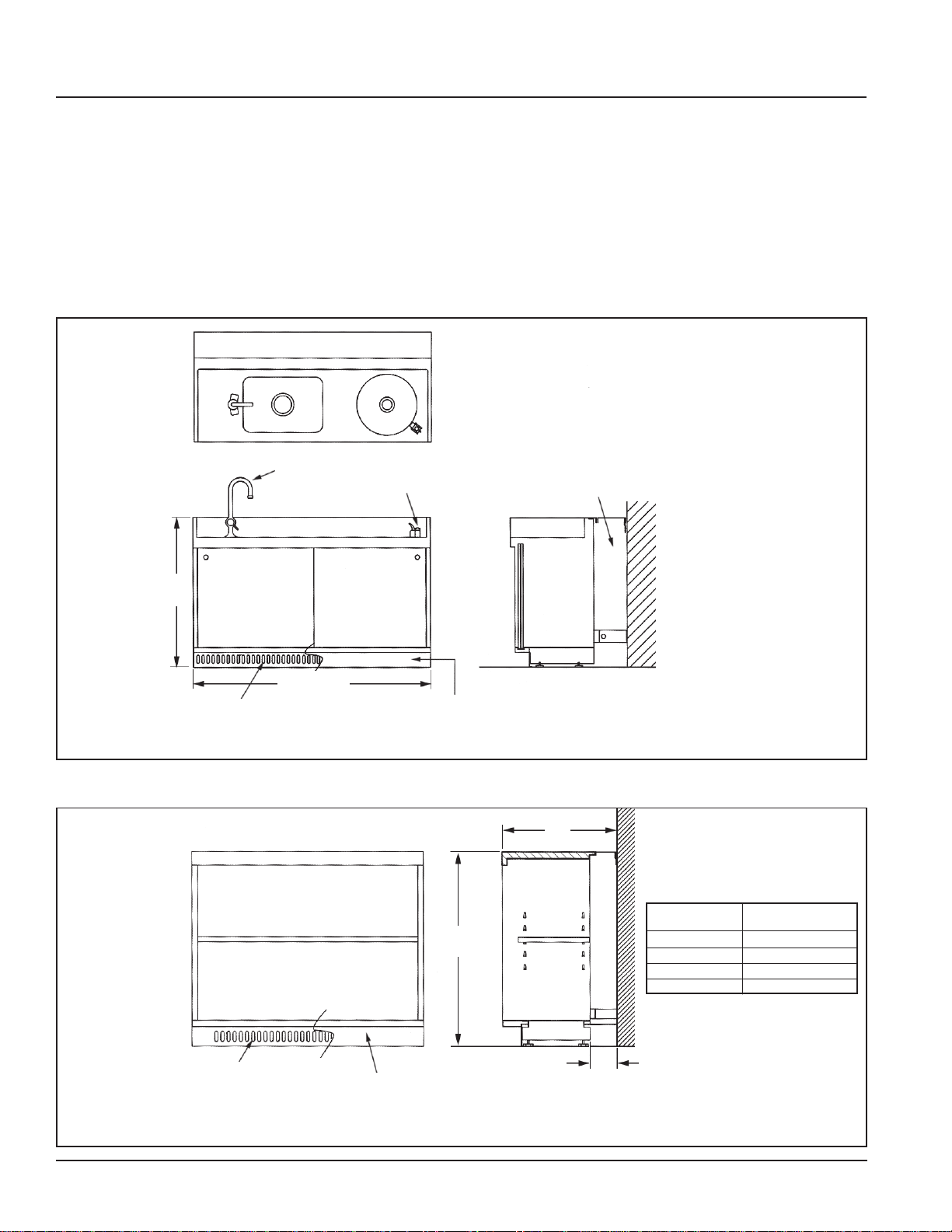
Details & Dimensions
Sink & Bubbler Cabinet
Notes:
1 Sink top is one-piece, stainless steel construction
with sound-deadening coating on the under side.
Front edge has raised lip continuously from end to
end.
2 Sliding doors available in decorator colors.
Figure 64: Sink and Bubbler
Top View
Faucet
Bubbler
30-1/8"
765mm
3 Sink and bubbler basin drains equipped with 1-1/2"
O.D. tail pieces, all chrome plated brass.
4 Sink faucet and bubbler valve are shipped loose for
eld installation by the installing contractor.
5 Sink and bubbler top is designed to project 1/16"
higher and 3/16" deeper than the adjoining cabinets, unit ventilator or end panels.
Note: Sink & Bubbler and Storage Cabinets, are
provided by others. Contact your McQuay
sales representative for details.
Piping Space
48" (1219mm)
Front Skirt with Air Inlet for
Radiation Style Cabinet
Front View
Figure 65: Standard Storage Cabinet
Front Skirt with Air Inlet for
Radiation Style Cabinet or
VentiMatic Shutter
Front View
Solid Skirt for Standard
Style Cabinet
Solid Skirt for Standard
Style Cabinet
30"
762mm
Side View
A
Side View
Total Depth Piping Space
“A” “B”
16-5/8" –
19-5/8" 3-9/16"
21-7/8" 5-13/16"
28" 11-15/16"
B
AAF-HermanNelson Model AEQ Unit Ventilator 53
Page 54

Details & Dimensions
Utility Compartment & Filler Sections
Filler sections are furnished in 18" and 24" lengths.
They are provided with enough hardware to assemble
one right hand and one left hand ller having a
combined length of 18"/24" or less. The minimum length
of one ller after cutting is 3". The ller section may be
used between a cabinet and the wall, between a unit
and the wall, between a unit and cabinets, or between
cabinets.
Figure 66: Accessories
12"
A
305mm
Top Panel
(Steel)
A A A
Note: Utility Compartments and Filler Sections are
provided by others. Contact your McQuay sales
representative for details.
18", 24"
Laminate T op
Laminate T op
Utility Compartment
Figure 67: Utility Compartment Details
A
30"
762mm
3"
(76mm)
12"
(305mm)
Front View
Total Depth Piping Space
“A” “B”
16-5/8" –
19-5/8" 3-9/16"
21-7/8" 5-13/16"
28" 11-15/16"
3" (76mm)
Side View
Corner Filler Sections
12"
(305mm)
B
28"
660mm
14"
356mm
1"
(25mm)
12"
(305mm)
54 AAF-HermanNelson Model AEQ Unit Ventilator
Page 55

Wiring Diagrams
CAUTION
Use copper conductors only. Unit terminals are not
designed to accept other types of conductors. Failure
to do so may damage the equipment.
DANGER
Disconnect alll electrical power before
servicing unit to prevent injury or death due
CAUTION
to electrical shock.
Refer to unit wiring diagram located on inside of right
front panel, for actual wiring. Improper wiring can cause
MicroTech II Wiring Diagram – Typical
Figure 68 - MicroTech II Wiring Diagram – Model AE Direct Expansion Cooling with Electric Heat, Valve Control 460 Volt/3Ph
Note: Please refer to Schematic on Unit Panel
AAF-HermanNelson Model AEQ Unit Ventilator 55
equipment and property damage.
Page 56

Wiring Diagrams
Typical Wall Sensors Diagram
Figure 68: Wall-Mounted Temperature Sensor Wiring for Wall Sensor
Figure 69: External Input Wiring Examples with or without Daisy Chaining of Units
Unit Ventilator #1
P1
Connector
GND
Comm
BI-6
BI-5
BI-4
BI-3
Unit Ventilator #2
P1
Connector
GND
Comm
BI-6
BI-5
BI-4
BI-3
Unit Ventilator #3
P1
Connector
GND
Comm
BI-6
BI-5
BI-4
BI-3
908A
907A
906A
905A
904A
908A
907A
906A
905A
904A
908A
907A
906A
905A
904A
896
896
896
Wire
Caps
Wire
Caps
Wire
Caps
Shield
Shield
Shield
External Input
Option 4 Device
(by Others)
WSHP
Boilerless System
(low temp switch)
External Input
Option 3 Device
(by Others)
Ventilation Lockout
(default) or
Exhaust Interlock
Factory Wiring
Field Wiring (by Others)
External Device (by Others)
External Input
Option 2 Device
(by Others)
Remote Shutdown
External Input
Option 1 Device
(by Others)
Unoccupied
Additional Units
56 AAF-HermanNelson Model AEQ Unit Ventilator
Page 57

Wiring Diagrams
Figure 70: External Output Wiring – Single Unit
Unit Ventilator
UVC
xBO-2
Comm
xBO-1
BO-6
BO-6
Comm
24vac Supply
24vac Comm
P6
Connector
Wire
Caps
601A
602A
603A
604A
605A
606A
608A
610A
Shield
Factory Wiring
Field Wiring (by Others)
External Device (by Others)
Figure 71: External Output Wiring – Multiple Units Shown
Unit Ventilator #1
UVC
XBO-2
Comm
XBO-1
BO-6
BO-6
Comm
24vac Supply
24vac Comm
P6
Connector
Wire
Caps
601A
602A
603A
604A
605A
606A
608A
610A
Shield
Unit Ventilator #2
UVC
XBO-2
Comm
XBO-1
BO-6
BO-6
Comm
24vac Supply
24vac Comm
P6
Connector
601A
602A
603A
604A
605A
606A
608A
610A
Wire
Caps
Shield
Unit Ventilator #...X (last unit)
UVC
XBO-2
Comm
XBO-1
BO-6
BO-6
Comm
24vac Supply
24vac Comm
P6
Connector
601A
602A
603A
604A
605A
606A
608A
610A
Wire
Caps
External Output
Option 1 Device
(by Others)
Lights On/Off
Signal
Motorized Water
Valve Open/Close
Additional Units
External Output
Option 2 Device
(by Others)
Fault Indication
or
or
Pump Restart
Signal
External Output
Option 3 Device
(by Others)
Auxiliary Heat
Signal
or
Exhaust Fan
On/Off Signal
External Output
Option 2 Device
(by Others)
Fault Indication
or
Pump Restart
Signal
Factory Wiring
Field Wiring (by Others)
External Device (by Others)
AAF-HermanNelson Model AEQ Unit Ventilator 57
Page 58

Guide Specications
AAF-HermanNelson Self-Contained Air Source Heat Pump Unit Ventilator
Model AEQ Guide Specications
General
Furnish and install where shown on plans, a complete
self-contained, air cooled, heating and cooling unit
ventilator. This unit shall meet capacities, airow and
conguration as shown on unit schedule.
Each standard unit must be listed by Underwriters
Laboratories Inc. (U.L.) as complying with all safety
standards.
The units shall ship fully assembled with the exception
of the end panels which shall be packaged separately
to allow easy access for piping and electrical rough-in.
(Option: Wall sleeves shall be shipped in advance of
unit for rough-in.)
Unit Construction
All internal sheet metal parts subject to corrosion must
be made of galvanized steel. The entire frame must
be welded construction to provide strength and rigidity.
Frames assembled with sheet metal fasteners are not
acceptable. Blow-thru design is not acceptable.
Cabinets
Exterior cabinet panels shall be constructed of heavygauge steel and every exposed corner must be welded
and ground smooth for appearance and durability.
All surfaces shall be cleaned and phosphatized, then
painted with an oven baked powder paint. Top surface
shall be Charcoal Bronze textured powder paint to resist
scratching and hide ngerprints. Front access panels
and top access door shall be supplied with tamper
resistant fasteners.
Removable discharge grille shall be constructed of
continuous, round edged, steel bars to provide a
10-degree vertical deection.
Adjustable side deection vanes shall be provided
beneath the discharge grille to give optimal lateral air
distribution. (Option: A 1/4" (6mm) mesh screen shall be
provided beneath the discharge grille to protect against
objects being dropped through the discharge grille.)
dynamically balanced. Motor shall be permanent split
capacitor (PSC) plug-in type located out of the airstream
and have an internal thermal overload device (autoreset). Fan speeds shall be controlled by High-MedLow-Off switch. Fan/coil arrangement shall be draw-thru
design for uniform coil face velocity and discharge air
temperature.
Fan motors and controls shall have each hot line
protected by factory installed cartridge type fuse(s) The
unit manufacturer shall provide one (1) spare motor for
each size and type of motor furnished as part of a unit
ventilator, except units having double extended shaft
motors shall be provided with one (1) spare fan board
assembly for each unit size.
All components of the fan/motor assembly shall be
removable from the front of the unit. The motor and fan
shaft shall have sleeve type bearings with precision
tolerances and shall not require oiling more than once
annually.
Condenser Fans and Motors
The fan board and fan housings shall be constructed of
galvanized steel. The fan motor and fan shaft shall have
permanently lubricated ball bearings. Motor shall be
permanent split capacitor (PSC) type. Fan wheels shall
be forward curved centrifugal type.
Outdoor/Room Air Dampers
Each unit shall be provided with separate room air and
outdoor air dampers. The room air damper shall be
constructed of aluminum and counterbalanced against
back pressure. Outdoor air damper shall be two-piece,
double wall construction with 1/2" (13mm) thick, 1.5
lbs. (.68 kg) density berglass insulation sandwiched
between welded galvanized steel blades. Outdoor air
damper shall have additional foam insulation on the
exterior of the blades and end partitions. Dampers shall
be tted with blended mohair seals along all sealing
edges. Damper bearings shall be made of nylon or other
material which does not require lubrication.
Room Air Fans and Motor
The motor and fan assembly shall be low speed design
and shall be double inlet, forward curved centrifugal
type with maximum fan speed of 1100 rpm. Fan wheels
shall be constructed of dark, high density, injection
molded polypropylene having high impact strength,
chemical resistance and thermal stability. Assembly
shall be direct drive type and shall be statically and
58 AAF-HermanNelson Model AEQ Unit Ventilator
Drain Pan
All units shall have a drain pan constructed of corrosion
resistant composite. A drain outlet shall be provided
on both ends of the pan. The drain hand of connection
shall be easily eld reversed to the opposite end. The
drain pan shall be able to be sloped in either direction
for proper condensate removal. Drain shall be provided
with an optional secondary, overow drain connection
on both ends of the pan.
Page 59

Guide Specications
Refrigeration System
The refrigeration section shall be constructed of
galvanized steel and shall include a factory sealed,
factory piped assembly consisting of a hermetically
sealed compressor, a condenser coil, condenser fan
and motor, and an evaporator coil. No condensate
drain piping system shall be required as the cooling
condensate is to be disposed of by directing it into
the condenser fan scrolls for re-evaporator on the hot
condenser coil. The equipment manufacturer is to
be fully responsible for the integrity of the refrigerant
piping and the entire refrigeration circult, including
compressor. Condenser and evaporator coils shall be
fully assembled and tested prior to shipment. The motor
compressor unit shall be vibration isolated internally and
externally and shall be connected in such a manner as
to prevent transmission of vibration to other components
within the section.
Single-phase only: Single-phase units shall have
permanent split capacitor (PSC) compressor motor with
compressor start relay.
Units with three-phase power: Shall utilize threephase compressors for balanced electrical compressor
loads.
The condenser coil shall be constructed of copper tubes
mechanically expanded to embossed aluminum plate
ns. The unit shall be so designed as to allow access
to the entering side of the condenser coil for cleaning
without opening the sealed refrigeration circuit. The
evaporator coil shall be constructed of copper tubing
having embossed aluminum plate ns mechanically
bonded thereto and shall be positioned above a plastic
drain pan.
Refrigerant shall be metered by a thermostatic
expansion valve in lieu of capillary tubing to achieve
evaporator performance and to protect the compressor
from oodback of liquid refrigerant. The refrigerant
section shall be adequately insulated to prevent
“sweating.”
The unit shall be furnished and wired with compressor
thermal/current overload and high pressure cutout.
Gauge ports shall be provided to allow reading of
refrigerant pressures at the suction and discharge of the
compressor. Compressor shall be equipped with internal
pressure relief valve to protect against excessive
pressure buildup.(Optional) Electric Coils
Heating elements shall be of the open wire type. Electric
heat shall be controlled in [three] stages. A capillary type
high limit thermostat shall be provided to disconnect
the heating elements through backup contactors if an
overheat condition is detected. A front panel interlock
switch shall be furnished to de-energize the electric
resistance heating element when center front panel is
opened. The water-to-refrigerant coil shall be stainless
steel plate- to plate heat exchanger. Either type shall be
constructed to be suitable for 300 lbs. (2069 kPa) water
working pressure and 450 lbs. (3104 kPa) refrigerant
pressure.
Filter
Filter shall be one-piece type. Throwaway lter shall be
factory furnished initially installed in the unit.
[Option: Furnish _____________ extra set(s) of throw-
away lters.]
[Option: Furnish one set of wire mesh permanent lters
as nal lter.]
[Option: Furnish one set of renewable (metal frame with
glass ber media) lters as nal lter.]
[Option: Furnish _____________ roll(s) of renewable
lter media.]
AAF-HermanNelson Model AEQ Unit Ventilator 59
Page 60

Guide Specications
Acoustical Features
The compressor shall be mounted on compressor
isolators for external vibration isolation. Compressor
enclosure panels shall be 16-gauge minimum.
Complete interior of compressor compartment shall
be lined with a multi-functional material that serves as
a sound barrier, an absorber of sound and also must
act as a decoupler to the compressor enclosure. This
multi-functional material shall have a mylar coating on
the face to act as a sound reector and to increase
the strength of the material. Damping material shall be
textured foam type.
The exterior of the compressor compartment shall be
coated with a high density damping material to eliminate
impact noise and vibration. The right-hand front panel
and the hinged top access door shall be coated with a
high density material to minimize noise and vibration.
VentiMatic Shutter (Room Exhaust)
Where indicated, the unit ventilator manufacturer
shall provide an “in-room” air relief VentiMatic shutter
mounted on a separate wall intake louver to prevent
excessive static pressure build-up In the room. The
VentiMatic shutter shall be constructed of galvanized
steel with shutter dampers of woven glass fabric
impregnated with silicone rubber.
Temperature Controls
The unit ventilator manufacturer shall provide factory
installed, calibrated, and tested temperature controls.
Units that are capable of providing up to 100% outside
air shall provide a microprocessor-based Direct
Digital Control (DDC) that can monitor conditions
and automatically adjust unit operations to maintain
these requirements. This DDC control shall have the
following tenant adjustments: (1) room temperature
setpoint, (2) minimum percent outdoor air setting,
and (3) unoccupied setpoint (offset). An LED status/
fault indicator shall be furnished for inspection and a
communications port shall be incorporated to allow
manipulation by a remote PC. The remote PC shall
be able to access and change pertinent operating
and room conditions from a remote location. The
microprocessor-based control must be capable of
communicating to a local IBM-compatible PC using the
RS-232 protocol. When using this remote PC, the unit
must be capable of reacting to changes made by the
remote PC. The remote PC must also be able to access
all pertinent operating and room conditions.
Network System
1. The unit control system shall perform all unit control
functions, unit diagnostics and safeties. The unit
shall operate in the standalone or network capable
mode of AAF-HermanNelson Model AEQ Unit Ven-
tilators 103 Guide Specications operation. Field
furnished and installed controls shall not be allowed.
When network capable, network communication
modules shall be factory installed, tested and able
to communicate via plug-in communication modules
that connect directly to the UVC using:
SELECT one:
a. LonMark Space Comfort Control that supports the
LonMark SCC prole number 8500-10 allowing
LonWorks network communication capability to the
UVC.
b. BACnet Master Slave/Token Passing (MS/TP) al-
lowing the UVC to inter-operate with systems that
use the BACnet (MS/TP) protocol with a conformance level of 3 meeting the requirements of ANSI/
ASHRAE 135- 1955 standard for BACnet systems.
c. Metasys N2 Open allowing Metasys N2 Open net-
work communication capability to the UVC.
2. Controls shall allow monitoring and adjustment from
a portable IBM compatible PC using the applicable
software. When using this PC and software, the
unit shall be capable of reacting to commands for
changes in control sequence and set points.
Room Temperature Sensor and Tenant
Override Options
Unit-Mounted
All units shall come equipped with a factory mounted
room temperature sensor located in a sampling
chamber (front, center panel) where room air is
continuously drawn through for fast response to
temperature changes in the room. When using a remote
wall-mounted temperature sensor the ability shall exist
to simply disconnect the unit-mounted temperature
sensor using the provided quick disconnect plug.
Tenant override switch shall be factory mounted next
to the Local User Interface (LUI) Touch Pad to provide
a momentary contact closure that causes the unit to
enter the “tenant override” operating mode for a set
time period (adjustable) of 120 minutes. The room
temperature sensor and override switch shall (SELECT
one):
A both be unit-mounted.
B be an optional wall-mounted temperature sensor,
with integral tenant override capability
60 AAF-HermanNelson Model AEQ Unit Ventilator
Page 61

Guide Specications
Sensor with Tenant Override and Setpoint
Adjustment
Wall-Mounted
A sensor with integral tenant override and status LED
shall be furnished with the unit ventilators. This sensor
shall also contain a manually adjustable temperature
setting allowing the controller setpoint to be increased
or decreased by 3°F (2°C).
(Optional) Night Control with Unit-Mounted
Time Clock
Each unit shall be furnished with a unit-mounted, eld
programmed time clock for day/night changeover. This
clock will provide up to 150 hours of operation during a
power outage.
Wall Sleeve
The galvanized steel, one-piece wall sleeve shall be
set in a wall opening and butted up directly against the
intake louver. Where it is not possible to butt the wall
sleeve against the wall intake louver, the contractor
shall fabricate and install horizontal air splitters between
the louver and wall sleeve to provide an airtight
separation between condenser discharge and return air.
The wall sleeve is to be permanently fastened in place
and shall be suitably sealed, caulked or grouted by the
contractor around the entire perimeter to prevent air
leakage.
The wall sleeve shall be tted with an electrical junction
box containing a main “on-off ” switch. All eld wiring
connections shall be made in this wall sleeve junction
box.
(It shall be the installing contractor’s responsibility to
make the nal load side power wiring connections
between the wall sleeve junction box and the unit
terminal block (including the wiring going to the electric
heating elements.The wall sleeve shall be cartoned
separately and shipped to the jobsite preceding the unit
ventilator. Junction box shall ship separately for eld
installation.)
Wall Intake Louver
The louver shall be supplied by the unit manufacturer
and shall be of heavy-gauge (unpainted, painted, or
clear anodized) aluminum construction. The louver shall
be of the vertical blade type and shall be divided in half
horizontally across the louver to prevent condenser air
recirculation. A 1/2" (13mm) square mesh bird screen
shall be provided on the backside of the wall intake
louver. All louvers shall be 28" (711mm) high by 2-1/2"
(57mm) thick and suitable for both masonry and panel
wall construction. The frame of the louver shall have
weep holes along the bottom. Lintels shall be provided
by the contractor above the louver opening.
Optional: Heavy-duty lattice grille horizontal and vertical
lines shall “line up” with the louver blades to present an
aesthetic appearance. Grille shall be fabricated from mill
nish aluminum.
Agency Listing
Unit ventilators shall be listed by Underwriters
Laboratories Inc. (U.L.) for the United States and
Canada. Unit ventilation rated per AHRI standard
840. Motors shall conform to the latest applicable
requirements of NEMA, IEEE, ANSI, and NEC
standards. Unit to be certied and labeled compliant
with the seismic design provisions of the International
Building Code (IBC) Chapter 16 and independent test
agency requirements of Chapter 17.
AAF-HermanNelson Model AEQ Unit Ventilator 61
Page 62

®
McQuay Training and Development
Now that you have made an investment in modern, efcient McQuay equipment, its care should be a high
priority. For training information on all McQuay HVAC products, please visit us at www.mcquay.com and
click on training, or call 540-248-9646 and ask for the Training Department.
Warranty
All McQuay equipment is sold pursuant to its standard terms and conditions of sale, including Limited
Product Warranty. Consult your local McQuay Representative for warranty details. Refer to Form
933-43285Y. To nd your local McQuay Representative, go to www.mcquay.com.
This document contains the most current product information as of this printing. For the most up-to-date
product information, please go to www.mcquay.com.
Manufactured in an ISO Certied Facility
©2010 McQuay International • www.mcquay.com • 800-432-1342
CAT 1650 (8-10)
 Loading...