


 Loading...
McDATA®
Sphereon™ 4400 Fabric Switch
Installation and Service Manual
P/N 620-000238-020
REV A

Record of Revisions and Updates
Revision |
Date |
Description |
|
|
|
|
|
|
620-000238-000 |
7/2005 |
General availability (GA) release of the manual. Describes Release 8.7 of the Enterprise Fabric Connectivity |
|
|
Manager application. |
|
|
|
620-000238-010 |
3/2006 |
Upodated for ROHs changes. |
|
|
|
620-000238-020 |
8/2006 |
Describes Release 9.0 of the Enterprise Fabric Connectivity Manager application. |
|
|
|
Copyright © 2005, 2006 McDATA Corporation. All rights reserved.
Printed August 2006
Third Edition
With the exception of downloading a copy of this publication for the customer’s own use, no part of this publication may be reproduced or distributed except as authorized under the terms of the "McDATA Corporation License to Copy Machine Readable Documentation."
The information contained in this document is subject to change without notice. McDATA Corporation assumes no responsibility for any errors that may appear.
All computer software programs, including but not limited to microcode, described in this document are furnished under a license, and may be used or copied only in accordance with the terms of such license. McDATA either owns or has the right to license the computer software programs described in this document. In addition, McDATA Corporation retains all rights, title and interest in the computer software programs.
ii McDATA Sphereon 4400 Fabric Switch Installation and Service Manual

Figures
1-1 |
Sphereon 4400 Fabric Switch (Front View) ............................................... |
1-3 |
1-2 |
Sphereon 4400 Fabric Switch (Rear View) ................................................ |
1-3 |
1-3 |
Management Server ................................................................................... |
1-10 |
1-4 |
24-Port Ethernet Hub ................................................................................. |
1-12 |
1-5 |
Door Key ...................................................................................................... |
1-14 |
1-6 |
Loopback Plug ............................................................................................ |
1-14 |
1-7 |
Fiber-Optic Protective Plug ....................................................................... |
1-15 |
1-8 |
Null Modem Cable ..................................................................................... |
1-15 |
2-1 |
Patch Cable and MDI Selector Configuration .......................................... |
2-7 |
2-2 |
Mounting Bracket Installation (Ethernet Hub) ........................................ |
2-8 |
2-3 |
Hardware View .......................................................................................... |
2-13 |
2-4 |
Identification View ..................................................................................... |
2-14 |
2-5 |
Date Time View .......................................................................................... |
2-15 |
2-6 |
Parameters View ......................................................................................... |
2-16 |
2-7 |
Fabric Parameters View ............................................................................. |
2-18 |
2-8 |
Network View ............................................................................................. |
2-20 |
2-9 |
Basic Information View ............................................................................. |
2-21 |
2-10 |
SNMP View ................................................................................................. |
2-23 |
2-11 |
SSH Configuration ..................................................................................... |
2-24 |
2-12 |
OSMS View .................................................................................................. |
2-25 |
2-13 |
SSL View ...................................................................................................... |
2-26 |
2-14 |
Maintenance Feature Installation View .................................................. |
2-28 |
2-15 |
Connection Description Dialog Box ........................................................ |
2-33 |
2-16 |
1U Management Server Connections ...................................................... |
2-36 |
2-17 |
Identification Changes Dialog Box .......................................................... |
2-42 |
2-18 |
Internet Protocol (TCP/IP) Properties Dialog Box ................................ |
2-43 |
2-19 |
Add New User Wizard .............................................................................. |
2-45 |
2-20 |
Properties Dialog Box (General Tab) ....................................................... |
2-46 |
Figures iii

Figures
2-21 |
Date/Time Properties Dialog Box (Time Zone Tab) .............................. |
2-47 |
2-22 |
Date/Time Properties Dialog Box (Date & Time Tab) .......................... |
2-48 |
2-23 |
Add User Dialog Box .................................................................................. |
2-50 |
2-24 |
Address Properties Dialog Box (IP Address Page) ................................ |
2-51 |
2-25 |
Hardware View ........................................................................................... |
2-54 |
2-26 |
New Feature Key Dialog Box .................................................................... |
2-56 |
2-27 |
Configure Date and Time Dialog Box ...................................................... |
2-58 |
2-28 |
Identification View ...................................................................................... |
2-60 |
2-29 |
Configure Switch Parameters Dialog Box ............................................... |
2-61 |
2-30 |
Configure Fabric Parameters Dialog Box ................................................ |
2-63 |
2-31 |
Configure Ports Dialog Box ....................................................................... |
2-65 |
2-32 |
Configure SNMP Dialog Box .................................................................... |
2-67 |
2-33 |
New Threshold Alert Dialog Box ............................................................. |
2-68 |
2-34 |
Email Event Notification Setup Dialog Box ............................................ |
2-71 |
2-35 |
InCD Icon (Unformatted CD) .................................................................... |
2-75 |
2-36 |
McDATA Filecenter Home Page .............................................................. |
2-81 |
3-1 |
Daisy-Chained Ethernet Hubs .................................................................. |
3-18 |
4-1 |
Clean Fiber-Optic Components .................................................................. |
4-6 |
4-2 |
McDATA Filecenter Home Page ................................................................ |
4-7 |
4-3 |
Port List View .............................................................................................. |
4-14 |
4-4 |
Diagnostics View ......................................................................................... |
4-18 |
4-5 |
System Files View ....................................................................................... |
4-21 |
4-6 |
Switch View ................................................................................................. |
4-22 |
4-7 |
Basic Information View .............................................................................. |
4-23 |
4-8 |
Firmware Upgrade View ........................................................................... |
4-24 |
4-9 |
Backup Configuration View ...................................................................... |
4-26 |
4-10 |
Restore Configuration View ...................................................................... |
4-27 |
4-11 |
Port List View .............................................................................................. |
4-35 |
4-12 |
Port Properties Dialog Box ........................................................................ |
4-39 |
4-13 |
Port Technology Dialog Box ...................................................................... |
4-40 |
4-14 |
Port Diagnostics Dialog Box ...................................................................... |
4-42 |
4-15 |
Swap Ports Dialog Box ............................................................................... |
4-44 |
4-16 |
Save Data Collection Dialog Box .............................................................. |
4-45 |
4-17 |
Set Online State Dialog Box ....................................................................... |
4-47 |
4-18 |
Firmware Library Dialog Box .................................................................... |
4-48 |
4-19 |
Backup and Restore Configuration Dialog Box ...................................... |
4-51 |
4-20 |
Reset Configuration Dialog Box ................................................................ |
4-52 |
4-21 |
Discover Setup Dialog Box ........................................................................ |
4-53 |
4-22 |
Address Properties Dialog Box ................................................................. |
4-54 |
4-23 |
InstallShield Wizard Dialog Box ............................................................... |
4-56 |
iv McDATA Sphereon 4400 Fabric Switch Installation and Service Manual

|
|
|
Figures |
|
|
|
|
5-1 |
SFP Optical Transceiver Removal and Replacement .............................. |
5-4 |
|
5-2 |
Redundant Power Supply Removal and Replacement ........................... |
5-8 |
|
6-1 |
Front-Accessible FRUs ................................................................................. |
6-2 |
|
6-2 |
Rear-Accessible FRUs .................................................................................. |
6-3 |
|
6-3 |
Miscellaneous Parts ...................................................................................... |
6-4 |
|
6-4 |
Power Cords and Receptacles .................................................................... |
6-5 |
|
B-1 |
InstallShield Wizard Dialog Box ................................................................ |
B-4 |
|
Figures v

Figures
vi McDATA Sphereon 4400 Fabric Switch Installation and Service Manual

Tables
2-1 |
Factory-Set Defaults (Product) ................................................................... |
2-1 |
2-2 |
Factory-Set Defaults (Management Server) .............................................. |
2-2 |
2-3 |
Installation Task Summary ......................................................................... |
2-2 |
2-4 |
Operational States and Symbols ............................................................... |
2-53 |
3-1 |
Factory-Set Defaults ..................................................................................... |
3-1 |
3-2 |
MAP Summary ............................................................................................. |
3-2 |
3-3 |
Event Codes versus Maintenance Action ................................................. |
3-2 |
3-4 |
MAP 100 Event Codes ............................................................................... |
3-11 |
3-5 |
MAP 200 Event Codes ............................................................................... |
3-13 |
3-6 |
MAP 200 Byte 0 FRU Codes ...................................................................... |
3-13 |
3-7 |
MAP 300 Error Messages .......................................................................... |
3-17 |
3-8 |
MAP 400 Event Codes ............................................................................... |
3-25 |
3-9 |
MAP 500 Event Codes ............................................................................... |
3-27 |
3-10 |
Link Incident Messages ............................................................................. |
3-27 |
3-11 |
Invalid Attachment Reasons and Actions ............................................... |
3-29 |
3-12 |
Inactive Port Reasons and Actions ........................................................... |
3-34 |
3-13 |
MAP 600 Event Codes ............................................................................... |
3-39 |
3-14 |
E_Port Segmentation Reasons and Actions ............................................ |
3-41 |
3-15 |
Port Fence Codes and Actions .................................................................. |
3-46 |
3-16 |
Fabric Merge Failure Reasons and Actions ............................................ |
3-50 |
4-1 |
Port Operational States ................................................................................ |
4-8 |
4-2 |
Port List Table ............................................................................................. |
4-14 |
4-3 |
Inspect Port Properties Table .................................................................... |
4-15 |
4-4 |
POM Data Table ......................................................................................... |
4-16 |
4-5 |
Inspect Port Transceiver Technology Table ............................................ |
4-16 |
4-6 |
Performance View Table ........................................................................... |
4-17 |
Tables vii

Tables
4-7 |
Statistical Information in Performance View .......................................... |
4-36 |
4-8 |
Port Properties Table .................................................................................. |
4-37 |
4-9 |
Port Technology Table ................................................................................ |
4-40 |
5-1 |
Concurrent FRUs ........................................................................................... |
5-2 |
6-1 |
Front-Accessible FRU Parts List .................................................................. |
6-2 |
6-2 |
Rear-Accessible FRU Parts List ................................................................... |
6-3 |
6-3 |
Miscellaneous Parts List ............................................................................... |
6-4 |
6-4 |
Power Cord and Receptacle List ................................................................. |
6-6 |
viii McDATA Sphereon 4400 Fabric Switch Installation and Service Manual

Contents
Preface ............................................................................................................................ |
|
xv |
Chapter 1 |
General Information |
|
|
Switch Description............................................................................ |
1-1 |
|
Field-Replaceable Units ............................................................ |
1-2 |
|
SFP Transceiver .......................................................................... |
1-3 |
|
Power Supply Assembly .......................................................... |
1-4 |
|
Controls, Connectors, and Indicators ............................................ |
1-5 |
|
RESET Button ............................................................................. |
1-5 |
|
Ethernet LAN Connector.......................................................... |
1-5 |
|
Power and System Error LEDs ................................................ |
1-6 |
|
FRU Status LEDs........................................................................ |
1-6 |
|
Maintenance Port....................................................................... |
1-6 |
|
Chassis Ground Connector ...................................................... |
1-6 |
|
Switch Specifications ........................................................................ |
1-6 |
|
Maintenance Approach.................................................................... |
1-8 |
|
Switch Management ......................................................................... |
1-9 |
|
Management Server .................................................................. |
1-9 |
|
Management Server Specifications ....................................... |
1-10 |
|
Ethernet Hub (Optional)......................................................... |
1-11 |
|
Error-Detection, Reporting, and Serviceability Features .......... |
1-12 |
|
Tools and Test Equipment.............................................................. |
1-14 |
|
Tools Supplied with the Product ........................................... |
1-14 |
|
Tools Supplied by Service Personnel .................................... |
1-15 |
Chapter 2 |
Installation Tasks |
|
|
Factory Defaults ................................................................................ |
2-1 |
|
Installation Task Summary .............................................................. |
2-2 |
Contents ix

Contents
Task 1: Verify Installation Requirements....................................... |
2-4 |
Task 2: Unpack, Inspect, and Install the Ethernet Hub (Optional). |
|
2-5 |
|
Unpack and Inspect Ethernet Hub ......................................... |
2-5 |
Desktop Installation .................................................................. |
2-6 |
Rack-Mount Installation ........................................................... |
2-7 |
Task 3: Unpack, Inspect, and Install the Product ......................... |
2-9 |
Unpack and Inspect Switch...................................................... |
2-9 |
Desktop Installation .................................................................. |
2-9 |
Rack-Mount Installation ......................................................... |
2-11 |
Task 4: Configure Product at the EFCM Basic Edition Interface |
|
(Optional)......................................................................................... |
2-12 |
Configure Product Identification .......................................... |
2-14 |
Configure Date and Time ....................................................... |
2-15 |
Configure Parameters ............................................................. |
2-16 |
Configure Fabric Parameters ................................................. |
2-17 |
Configure Network Information........................................... |
2-19 |
Configure Basic Port Information ......................................... |
2-21 |
Configure Port BB_Credit....................................................... |
2-22 |
Configure Port NPIV............................................................... |
2-22 |
Configure SNMP ..................................................................... |
2-23 |
Enable CLI ................................................................................ |
2-24 |
Enable or Disable the CLI for SSH ........................................ |
2-24 |
Enable or Disable Host Control............................................. |
2-25 |
Configure SSL Encryption...................................................... |
2-25 |
Installing PFE Keys (Optional) .............................................. |
2-27 |
Configure Security................................................................... |
2-29 |
Configure Interswitch Links .................................................. |
2-30 |
Task 5: Configure Product Network Information (Optional)... |
2-32 |
Task 6: Unpack, Inspect, and Install the Management Server..2-35 |
|
Task 7: Configure Server Password and Network Addresses..2-38 |
|
Configure Password................................................................ |
2-38 |
Configure Private LAN Addresses ....................................... |
2-39 |
Configure Public LAN Addresses (Optional) ..................... |
2-39 |
Task 8: Configure Management Server Information ................. |
2-40 |
Access the Management Server Desktop............................. |
2-40 |
Configure Management Server Names................................ |
2-41 |
Configure Gateway and DNS Server Addresses ................ |
2-42 |
Task 9: Configure Windows Operating System Users .............. |
2-44 |
Change Default Administrator Password ........................... |
2-44 |
Add a New User ...................................................................... |
2-44 |
Change User Properties.......................................................... |
2-45 |
Task 10: Set Management Server Date and Time ....................... |
2-46 |
x McDATA Sphereon 4400 Fabric Switch Installation and Service Manual
|
|
|
Contents |
|
|
|
|
|
Task 11: Configure the Call-Home Feature (Optional) ............. |
2-48 |
|
|
Task 12: Assign User Names and Passwords............................. |
2-49 |
|
|
Task 13: Configure the Product to the Management Application... |
||
|
2-51 |
|
|
|
Task 14: Record or Verify Server Restore Information.............. |
2-52 |
|
|
Task 15: Verify Product-to-Server Communication................... |
2-53 |
|
|
Task 16: Configure PFE Key (Optional) ...................................... |
2-55 |
|
|
Task 17: Configure Management Server (Optional).................. |
2-56 |
|
|
Task 18: Set Product Date and Time ............................................ |
2-57 |
|
|
Task 19: Configure the Element Manager Application............. |
2-59 |
|
|
Configure Product Identification.......................................... |
2-59 |
|
|
Configure Product Parameters.............................................. |
2-61 |
|
|
Configure Fabric Parameters................................................. |
2-62 |
|
|
Configure Ports ....................................................................... |
2-64 |
|
|
Configure SNMP..................................................................... |
2-66 |
|
|
Configure Threshold Alerts................................................... |
2-68 |
|
|
Enable EFCM Basic Edition and Telnet Access................... |
2-70 |
|
|
Configure, Enable, and Test E-mail Notification................ |
2-70 |
|
|
Configure and Enable Ethernet Events................................ |
2-72 |
|
|
Configure, Enable, and Test Call-Home Event Notification..... |
||
|
2-72 |
|
|
|
Configure Security .................................................................. |
2-73 |
|
|
Configure Interswitch Links.................................................. |
2-74 |
|
|
Task 20: Back Up Configuration Data ......................................... |
2-75 |
|
|
Task 21: Cable Fibre Channel Ports ............................................. |
2-77 |
|
|
Task 22: Configure Zoning (Optional) ........................................ |
2-78 |
|
|
Task 23: Connect Product to a Fabric Element (Optional)........ |
2-79 |
|
|
Task 24: Register with the McDATA Filecenter ......................... |
2-80 |
|
Chapter 3 |
Maintenance Analysis Procedures |
|
|
|
Factory Defaults ............................................................................... |
3-1 |
|
|
Quick Start......................................................................................... |
3-2 |
|
|
MAP 0000: Start MAP...................................................................... |
3-5 |
|
|
MAP 0100: Power Distribution Analysis.................................... |
3-10 |
|
|
MAP 0200: POST Failure Analysis .............................................. |
3-13 |
|
|
MAP 0300: Loss of Server Communication................................ |
3-14 |
|
|
MAP 0400: FRU Failure Analysis................................................. |
3-24 |
|
|
MAP 0500: Port Failure or Link Incident Analysis.................... |
3-26 |
|
|
MAP 0600: Fabric or ISL Problem Analysis ............................... |
3-38 |
|
Chapter 4 |
Repair Information |
|
|
Contents xi

Contents
|
Procedural Notes .............................................................................. |
4-2 |
|
Power On Switch .............................................................................. |
4-2 |
|
Power Off Switch .............................................................................. |
4-3 |
|
IML or Reset Switch ......................................................................... |
4-3 |
|
IML .............................................................................................. |
4-4 |
|
Reset ............................................................................................ |
4-4 |
|
Clean Fiber-Optic Components ...................................................... |
4-5 |
|
Download Firmware or Software from the Filecenter ................ |
4-6 |
|
Port LED Diagnostics ....................................................................... |
4-8 |
|
Repair Procedures - EFCM Basic Edition.................................... |
4-10 |
|
Obtaining Log Information.................................................... |
4-10 |
|
Performing Port Diagnostics.................................................. |
4-13 |
|
Collecting Maintenance Data................................................. |
4-20 |
|
Setting Online State................................................................. |
4-21 |
|
Blocking or Unblocking a Port .............................................. |
4-22 |
|
Upgrading Firmware .............................................................. |
4-23 |
|
Managing Configuration Data .............................................. |
4-25 |
|
Repair Procedures - SAN Management Application ................ |
4-28 |
|
Obtaining Fabric Log Information ........................................ |
4-29 |
|
Obtaining Switch Log Information....................................... |
4-30 |
|
Performing Port Diagnostics.................................................. |
4-35 |
|
Collecting Maintenance Data................................................. |
4-45 |
|
Setting Online State................................................................. |
4-46 |
|
Blocking or Unblocking a Port .............................................. |
4-47 |
|
Upgrading Firmware .............................................................. |
4-48 |
|
Managing Configuration Data .............................................. |
4-51 |
|
Installing or Upgrading Software ......................................... |
4-55 |
Chapter 5 |
Removal and Replacement Procedures |
|
|
Procedural Notes .............................................................................. |
5-1 |
|
ESD Procedures................................................................................. |
5-2 |
|
Field-Replaceable Units ................................................................... |
5-2 |
|
RRP 1: SFP Optical Transceiver ...................................................... |
5-3 |
|
RRP 2: Redundant Power Supply .................................................. |
5-7 |
Chapter 6 |
Illustrated Parts Breakdown |
|
|
RoHS Information............................................................................. |
6-1 |
|
Front-Accessible FRUs ..................................................................... |
6-2 |
|
Rear-Accessible FRUs....................................................................... |
6-3 |
|
Miscellaneous Parts.......................................................................... |
6-4 |
|
Power Cords and Receptacles......................................................... |
6-5 |
xii McDATA Sphereon 4400 Fabric Switch Installation and Service Manual

|
|
Contents |
|
|
|
Appendix A Event Code Tables |
|
|
System Events (000 through 199) ................................................. |
A-2 |
|
Power Supply Events (200 through 299) ................................... |
A-24 |
|
Fan Events (300 through 399) ..................................................... |
A-28 |
|
CTP Card Events (400 through 499) .......................................... |
A-35 |
|
Port Events (500 through 599) .................................................... |
A-39 |
|
Appendix B Restore Management Server |
|
|
Requirements ................................................................................... |
B-1 |
|
Restore Management Server Procedure ....................................... |
B-2 |
|
Index ............................................................................................................................... |
I-1 |
|
Contents xiii

Contents
xiv McDATA Sphereon 4400 Fabric Switch Installation and Service Manual
Preface
Who Should Use this Manual
Organization of this Manual
This publication is part of a documentation suite that supports the McDATA® Sphereon 4400 Fabric Switch.
Use this publication if you are a trained installation and service representative experienced with the product, storage area network (SAN) technology, and Fibre Channel technology.
The product contains no customer-serviceable parts that require internal access to the product during normal operation or prescribed maintenance conditions. In addition, refer to this manual for instructions prior to performing any maintenance action.
This publication includes six chapters and two appendices organized as follows:
Chapter 1, General Information - This chapter describes the switch, including field-replaceable units (FRUs), controls, connectors, and indicators, and switch specifications. The chapter also describes the maintenance approach, error detection and reporting features, serviceability features, software diagnostic features, and tools and test equipment.
Chapter 2, Installation Tasks - This chapter describes tasks to install, configure, and verify operation of the switch, optional Ethernet hub, and rack-mount management server.
Chapter 3, Maintenance Analysis Procedures - This chapter describes maintenance analysis procedures (MAPs) to fault isolate a switch problem to an individual FRU.
Preface xv

Preface
Chapter 4, Repair Information - This chapter describes supplementary diagnostic and repair procedures for a failed switch. The chapter includes procedures to display and use log information, perform port diagnostics, manage configuration data, collect maintenance data, power-on, power-off, and reset the switch, set the switch online or offline, block ports, manage switch firmware, clean fiber optics, and install or upgrade management server software.
Chapter 5, Removal and Replacement Procedures - This chapter describes procedures to remove and replace switch FRUs.
Chapter 6, Illustrated Parts Breakdown - This chapter illustrates, describes, and shows the location of switch FRUs. In addition, switch FRUs are cross-referenced to corresponding part numbers.
Appendix A, Event Code Tables - This appendix provides an explanation of event codes that appear at the EFCM Basic Edition interface or Element Manager application. The event severity and a recommended course of action in response to each event are also provided.
Appendix B, Restore Management Server - This appendix provides the instructions to restore all required switch applications to the management server in case of a hard drive failure.
An Index is also provided.
Related Publications Other publications that provide additional information about the switch include:
•McDATA Products in a SAN Environment - Planning Manual
(620-000124).
•McDATA Sphereon 4400 Fabric Switch Element Manager User Manual (620-000241).
•McDATA Product Safety Notices (620-000247).
•EFC Manager Software Release 8.7 User Manual (620-000170).
•McDATA EFCM Basic Edition User Manual (620-000240).
•McDATA SNMP Support Manual (620-000131).
•McDATA E/OS Command Line Interface User Manual (620-000134).
xvi McDATA Sphereon 4400 Fabric Switch Installation and Service Manual

Ordering Printed
Manuals
Where to Get Help
Forwarding
Publication
Comments
Preface
•McDATA EFCM Lite Installation Instructions (958-000171).
•1U Server Rack-Mount Kit Installation Instructions (958-000310).
•McDATA FC-512 Fabricenter Equipment Cabinet Installation and Service Manual (620-000100).
To order a copy of this publication, submit a purchase order as described in Ordering McDATA Documentation Instructions at http://www.mcdata.com or contact your McDATA sales representative.
For technical support, McDATA end-user customers should call the phone number located on the service label attached to the front or rear of the hardware product.
McDATA’s “Best in Class” Technical Support Center and Network Operations Center (NOC) provide single points of contact for customers seeking help. These centers will research, explore, and resolve inquiries or service requests regarding McDATA products and services. The centers are staffed 24 hours a day, 7 days a week, including holidays.
To expedite warranty entitlement, please have your product serial number available.
McDATA Corporation
11802 Ridge Parkway
Broomfield, CO 80021
For SAN Router issues, contact the Network Operations Center (NOC) at:
(800) 752-8061 or (763) 268-6600.
For all other products, contact the Technical Support Center at:
(800) 752-4572 or (720) 558-3910.
E-mail: support@mcdata.com
Please send comments to the McDATA technical support center by telephone, or e-mail. The numbers and e-mail address are listed above. Please identify the page numbers and details.
Preface xvii
Preface
Trademarks The following terms, indicated by a registered trademark symbol
(®) or trademark symbol (™) on first use in this publication, are trademarks of McDATA Corporation in the United States or other countries or both:
Registered Trademarks |
Trademarks |
Fabricenter® |
EON™ |
HotCAT® |
OPENconnectors™ |
McDATA® |
Sphereon™ |
Multi-Capable Storage |
|
Network Solutions® |
|
Networking the World’s |
|
Business Data® |
|
OPENready® |
|
SANtegrity® |
|
Laser Compliance
Statement
Federal
Communications
Commission (FCC)
Statement
All other trademarked terms, indicated by a registered trademark symbol (®) or trademark symbol (™) on first use in this publication, are trademarks of their respective owners in the United States or other countries or both.
Product laser transceivers are tested and certified in the United States to conform to Title 21 of the Code of Federal Regulations (CFR), Subchapter J, Parts 1040.10 and 1040.11 for Class 1 laser products. Transceivers are tested and certified to be compliant with International Electrotechnical Commission IEC825-1 and European Norm EN60825-1 and EN60825-2 regulations for Class 1 laser products. Class 1 laser products are not considered hazardous. The transceivers are designed to prevent human access to laser radiation above a Class 1 level during normal operation or prescribed maintenance conditions.
Products generate, use, and can radiate radio frequency energy, and if not installed and used in accordance with instructions provided, may cause interference to radio communications. Products are tested and found to comply with the limits for Class A and Class B computing devices pursuant to Subpart B of Part 15 of the FCC Rules, which are designed to provide reasonable protection against such interference in a residential environment. Any modification or change made to a product without explicit approval from McDATA, by means of a written endorsement or through published literature,
xviii McDATA Sphereon 4400 Fabric Switch Installation and Service Manual

Canadian EMC
Statements
Preface
invalidates the service contract and voids the warranty agreement with McDATA.
The statements below indicate product compliance with Interference Causing Equipment Standard (ICES) and Norme sur le Matériel Brouiller (NMB) electromagnetic compatibility (EMC) requirements as set forth in ICES/NMB-003, Issue 4.
•This Class A or Class B digital apparatus complies with Canadian ICES-003.
•Cet appareil numérique de la classe A et classe B est conforme à la norme NMB-003 du Canada.
Preface xix

Preface
United States and
Canada UL
Certification
International Safety
Conformity
Declaration (CB
Scheme)
European Union
Conformity
Declarations and
Directives (CE Mark)
The C-UL-US mark on a product indicates compliance with American National Standards Institute (ANSI) and Standards Council of Canada (SCC) safety requirements as tested, evaluated, and certified by Underwriters Laboratories Inc. (UL) and Underwriters Laboratories of Canada (ULC).
A certification bodies (CB) test report supporting a product indicates safety compliance with the International Electrotechnical Commission (IEC) system for conformity testing and certification of electrical equipment (IECEE) CB scheme. The scheme is a multilateral agreement among participating countries and certification organizations that accepts test reports certifying the safety of electrical and electronic products.
The CE mark on a product indicates compliance with the following regulatory requirements as set forth by European Norms (ENs) and relevant international standards for commercial and light industrial information technology equipment (ITE):
•EN55022: 1998 - ITE-generic radio frequency interference (RFI) emission standard for domestic, commercial, and light industrial environments, including electrical business equipment.
•EN55024-1: 1998 - ITE-generic electromagnetic immunity standard for domestic, commercial, and light industrial environments, including electrical business equipment.
•EN60950/A11:1997 - ITE-generic electrical and fire safety standard for domestic, commercial, and light industrial environments, including electrical business equipment.
•EN61000-3-2:1995 - ITE-generic harmonic current emissions standard for domestic, commercial, and light industrial environments (equipment with rated current less than or equal to 16 amperes per phase).
•EN61000-3-3:1995 - ITE-generic voltage fluctuation and flicker standard (low-voltage power supply systems) for domestic, commercial, and light industrial environments (equipment with rated current less than or equal to 16 amperes per phase).
xxMcDATA Sphereon 4400 Fabric Switch Installation and Service Manual
European Union EMC
and Safety
Declaration (N-Mark)
Argentina UL
Certification
Preface
In addition, the European Union (EU) Council has implemented a series of directives that define product safety standards for member countries. The following directives apply:
•Products conform with all protection requirements of EU directive 89/336/EEC (Electromagnetic Compatibility Directive) in accordance with the laws of the member countries relating to EMC emissions and immunity.
•Products conform with all protection requirements of EU directive 73/23/EEC (Low-Voltage Directive) in accordance with the laws of the member countries relating to electrical safety.
•Products conform with all protection requirements of EU directive 93/68/EEC (Machinery Directive) in accordance with the laws of the member countries relating to safe electrical and mechanical operation of the equipment.
McDATA does not accept responsibility for any failure to satisfy the protection requirements of any of these directives resulting from a non-recommended or non-authorized modification to a product.
The N-mark on a product indicates compliance with European Union EMC and safety requirements as tested, evaluated, and certified by the Norwegian Board for Testing and Approval of Electrical Equipment (Norges Elektriske Materiellkontroll or NEMKO) laboratory or a NEMKO-authorized laboratory.
The UL Argentina plus S mark (UL-AR-S mark) on a product indicates compliance with Direccion Nacional de Comercio Interior (DNCI) Resolution Number 92/98, Phase III (for information technology equipment safety). The mark is certified by UL de Argentina, S.R.L., and accredited by the Argentine Accreditation Organization (OAA).
Australia and New
Zealand C-Tick Mark
The Australia and New Zealand regulatory compliance mark (C-tick mark) on a product indicates compliance with regulatory requirements for EMC (for information technology equipment) as set forth by the Australian Communications Authority (ACA) and the Radio Spectrum Management Group (RSM) of New Zealand.
Preface xxi

Preface
People’s Republic of
China CCC Mark
Chinese National
Standards Statement
German GS Mark
The China Compulsory Certification mark (CCC mark) on a product indicates compliance with People’s Republic of China regulatory requirements for safety and EMC (for information technology equipment) as set forth by the National Regulatory Commission for Certification and Accreditation.
The Taiwanese Bureau of Standards, Metrology, and Inspection mark (BSMI mark) and the Chinese National Standards (CNS) statement below indicate product compliance with Taiwanese regulatory requirements. The statement indicates in a domestic environment the product may cause radio interference, in which case the user is required to take corrective actions.
The Geprüfte Sicherheit mark (GS mark) on a product indicates compliance with the German Safety of Equipment Act as tested by Underwriters Laboratories International Demko A/S, and accredited by the Central Office of Safety of the German Länder (Zentralstelle der Länder für Sicherheitstechnik or ZLS).
Japanese VCCI
Statement
The Voluntary Control Council for Interference (VCCI) statement below applies to information technology equipment, and indicates product compliance with Japanese regulatory requirements. The statement indicates a product is a Class A or Class B product, and in a domestic environment may cause radio interference, in which case the user is required to take corrective actions.
xxii McDATA Sphereon 4400 Fabric Switch Installation and Service Manual

Preface
Korean MIC Mark The Korean Ministry of Information and Communications mark (MIC mark) on a product indicates compliance with regulatory requirements for safety and EMC (for information technology equipment) as authorized and certified by the Korean Radio Research Institute (RRI).
Mexican NOM Mark
NOM
Russian GOST
Certification
South African SABS
Certification
European Union Waste
Managment
Information
The Official Mexican Standard (Normas Oficiales Mexicanas or NOM) mark on a product indicates compliance with regulatory requirements for safety (for information technology equipment) as authorized and accredited by the National System of Accreditation of Testing Laboratories (Sistema Nacional de Acreditamieno de Laboratorios de Pruebas or SINALP).
The Russian Gosudarstvennyi Standart (GOST) mark on a product indicates compliance with regulatory requirements for safety and EMC (for information technology equipment) as authorized and accredited by the State Committee for Standardization, Metrology and Certification.
The South African Bureau of Standards (SABS) mark on a product indicates compliance with regulatory requirements for safety and EMC (for information technology equipment) as authorized and accredited by the Independent Communications Authority of South Africa (ICASA).
Do not discard a product. European Union Directive 2002/96/EC requires a product to be recycled at the end of its useful life. Follow all waste management actions defined by this directive. Directive requirements may be superseded by EU member nation law. Perform the following to identify pertinent information:
1.Review the original purchase contract to determine a contact regarding waste management of a product, or
2.Contact the company from which a product was procured.
Preface xxiii
Preface
Danger and Attention
Statements
The following DANGER statements appear in this publication and describe safety practices that must be observed while installing or servicing the product. A DANGER statement provides essential information or instructions for which disregard or noncompliance may result in death or severe personal injury.
DANGER statements have a numerical ID (displayed in parentheses) at the end of each statement. Use the numerical ID to locate translated statements in the McDATA Product Safety Notices (620-000247) manual delivered with the product.
DANGER
Use the supplied power cords. Ensure the facility power receptacle is the correct type, supplies the required voltage, and is properly grounded. (D004)
DANGER
Disconnect the power cords. (D005)
The following ATTENTION statements appear in this publication and describe practices that must be observed while installing or servicing a product. An ATTENTION statement provides essential information or instructions for which disregard or noncompliance may result in equipment damage or loss of data.
ATTENTION ! Prior to servicing a product, management server, or customer-supplied server, determine the Ethernet LAN configuration. Installation of products and servers on a public customer intranet can complicate problem determination and fault isolation.
ATTENTION ! Activating a preferred path can result in receipt of out-of- order frames if the preferred path differs from the current path, if input and output (I/O) is active from the source port, and if congestions is present on the current path.
ATTENTION ! Do not remove a power supply unless a replacement FRU is immediately available. To avoid product overheating, a removed power supply must be replaced within five minutes.
xxiv McDATA Sphereon 4400 Fabric Switch Installation and Service Manual

Preface
ATTENTION ! A reset should only be performed if a CTP card failure is indicated. Do not reset a managed product unless directed to do so by a procedural step or the next level of support.
ATTENTION ! This procedure deletes all data from the C: hard drive partition.
ATTENTION ! Contents of the data directory are backed up to the management server’s CD-RW drive when directory contents change. To ensure trouble-free backups, always leave a CD in the drive. Ensure data is not being written to or read from the CD-RW drive before removing the
CD. Removing the CD during a backup or restore operation can corrupt data.
General Precautions When installing or servicing the product, follow these practices:
•Always use correct tools.
•Always use correct replacement parts.
•Keep all paperwork up to date, complete, and accurate.
ESD Precautions Follow these electrostatic discharge (ESD) procedures:
•If the product is connected to facility power (grounded), wear an ESD wrist strap and grounding cable connected to the product chassis.
•If the product is not connected to facility power (not grounded), wear an ESD wrist strap and grounding cable connected to an approved bench grounding point.
•Touch the product chassis once before performing a procedure, and once each minute during the procedure.
•Store ESD-sensitive FRUs in antistatic packaging.
Preface xxv

Preface
xxvi McDATA Sphereon 4400 Fabric Switch Installation and Service Manual

1
General Information
The McDATA® Sphereon™ 4400 Fabric Switch provides 16 ports of low-cost and high-performance dynamic Fibre Channel connectivity for switched fabric or arbitrated loop devices. This function allows low-cost, low-bandwidth workgroup (edge) devices to communicate with mainframe servers, mass storage devices, or other peripherals, and ultimately be incorporated into an enterprise storage area network (SAN) environment. This chapter describes:
•The switch, including field-replaceable units (FRUs), controls, connectors, indicators, and specifications.
•Maintenance approach.
•Switch management.
•Error detection, reporting, and serviceability features.
•Tools and test equipment.
Switch Description
The switch provides Fibre Channel connectivity through generic mixed ports (GX_Ports). Ports operate at 1.0625, 2.1250, or 4.2500 gigabits per second (Gbps), and can be configured as:
•Fabric ports (F_Ports) to provide direct connectivity for switched fabric devices.
Switch Description |
1-1 |
|
|

General Information
1
•Expansion ports (E_Ports) to provide interswitch link (ISL) connectivity to fabric directors and switches.
•Fabric loop ports (FL_Ports) to provide connectivity and fabric attachment for Fibre Channel arbitrated loop (FC-AL) devices.
The switch is installed on a table or desktop, mounted in an FC-512 Fabricenter® equipment cabinet, or mounted in any standard 19-inch equipment rack.
Operators with a browser-capable PC and Internet connectivity can manage the switch through a firmware-resident Enterprise Fabric Connectivity Manager (EFCM) Basic Edition interface. The interface manages only a single switch, and provides a graphical user interface (GUI) that supports configuration, statistics monitoring, operation, and maintenance. The interface is opened from a web browser running Netscape Navigator® 4.6 (or higher) or Microsoft® Internet Explorer 4.0 (or higher).
As an option, the switch is managed through a one-unit (1U) high, rack-mount management server running a Java™-based SAN management application ( EFCM 8.7 or later) and the switch Element Manager application.
Multiple switches and the 1U server communicate on a local area network (LAN) through one or more 10/100 Base-T Ethernet hubs. The 24-port Ethernet hubs are optional and ordered with the switch. Up to three hubs are daisy-chained as required to provide additional Ethernet connections as more switches (or other managed products) are installed on a network.
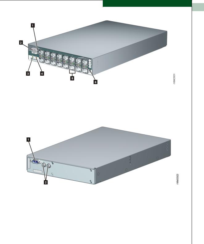
Field-Replaceable The switch provides a modular design that enables quick removal Units and replacement of FRUs, including small form factor pluggable
(SFP) optical transceivers and power supply assemblies. Figure 1-1 illustrates the front of the switch and shows the:
1.RESET button.
2.Ethernet LAN connector.
3.Green power (PWR) light-emitting diode (LED).
4.Amber system error (ERR) LED.
5.SFP optical transceivers (16).
6.Chassis ground (GND) connector.
1-2 McDATA Sphereon 4400 Fabric Switch Installation and Service Manual
General Information
1
Figure 1-1 Sphereon 4400 Fabric Switch (Front View)
Figure 1-2 illustrates the rear of the switch and shows the:
1.RS-232 maintenance port.
2.External power supply connectors (2).
Figure 1-2 Sphereon 4400 Fabric Switch (Rear View) |
|
|
|
|
|
SFP Transceiver |
Multimode fiber-optic cables attach to switch ports through SFP |
|
|
transceivers with duplex LC® connectors, and can be detached from |
|
|
switch ports (through a 10-pin interface) for easy replacement. |
|
|
Tri-rate (1.0625, 2.1250, or 4.2500 Gbps) shortwave laser transceivers |
|
|
(850 nm) provide connectivity: |
|
|
Switch Description |
|
|
1-3 |
|
|
|
|

|
|
|
General Information |
|
|
|
1 |
|
|
|
|||
|
|
|
|
|
|
|
|
|
|
|
• At 500 meters (1.0625 Gbps) through 50-micron multimode |
||
|
|
|
|
|
||
|
|
|
|
|
||
|
|
|
|
|
fiber-optic cable. |
|
|
|
|
|
|
• At 300 meters (2.1250 Gbps) through 50-micron multimode |
|
|
|
|
|
|
fiber-optic cable. |
|
|
|
|
|
|
• At 150 meters (4.2500 Gbps) through 50-micron multimode |
|
|
|
|
|
|
fiber-optic cable. |
|
|
|
|
|
|
• At 300 meters (1.0625 Gbps) through 62.5-micron multimode |
|
|
|
|
|
|
fiber-optic cable. |
|
|
|
|
|
|
• At 150 meters (2.1250 Gbps) through 62.5-micron multimode |
|
|
|
|
|
|
fiber-optic cable. |
|
|
|
|
|
|
• At 70 meters (4.2500 Gbps) through 62.5-micron multimode |
|
|
|
|
|
|
fiber-optic cable. |
|
|
|
|
|
|
Tri-rate longwave laser (1.0625, 2.1250, or 4.2500 Gbps) are also |
|
|
|
|
|
|
available. Longwave laser transceivers provide connectivity at 4 |
|
|
|
|
|
|
kilometers and 10 kilometers through singlemode fiber-optic cable. |
|
|
|
|
|
|
(Additional distances will be available in the future. 2Gb LW optics |
|
|
|
|
|
|
are currently available for 10, 20, 35 and 80 kilometers.) |
|
|
|
|
|
|
The switch also provides a predictive optics monitoring (POM) |
|
|
|
|
|
|
feature that monitors operation of SFP optical transceivers. Digital |
|
|
|
|
|
|
diagnostics-enabled optical transceivers report temperature, voltage |
|
|
|
|
|
|
current, transceiver power, and receiver power to product firmware. |
|
|
|
|
|
|
Optical transceivers also provide vendor-specific threshold values for |
|
|
|
|
|
|
these parameters. |
|
|
|
|
|
|
|
|
|
|
|
Power Supply |
The switch is delivered with one external power supply assembly. |
||
|
|
|
Assembly |
The power supply steps down and rectifies facility input power to |
||
|
|
|
|
|
provide 12 volts direct current (VDC) to the control processor (CTP) |
|
|
|
|
|
|
card. The power supply also provides input filtering, overvoltage |
|
|
|
|
|
|
protection, and overcurrent protection. The power supply is input |
|
|
|
|
|
|
rated at 100 to 240 volts alternating current (VAC). |
|
|
|
|
|
|
A second power supply can be installed as an option. When a second |
|
|
|
|
|
|
power supply is detected, the switch automatically enables high |
|
|
|
|
|
|
availability (HA) mode. With HA mode enabled, either power supply |
|
|
|
|
|
|
can be replaced while the switch is operational. Each power supply |
|
|
|
|
|
|
has a separate connection to the CTP card to allow for independent |
|
|
|
|
|
|
AC power sources. |
|
|
|
|
|
|
Three internal cooling fans provide airflow for the CTP card, as well |
|
|
|
|
|
|
as redundancy for continued operation if a single fan fails. |
|
1-4 McDATA Sphereon 4400 Fabric Switch Installation and Service Manual
Loading...