

Page 1
McDATA
®
Sphereon™ 4400 Fabric Switch
Installation and Service Manual
P/N 620-000238-020
REV A
Page 2

Record of Revisions and Updates
Revision Date Description
620-000238-000 7/2005 General availability (GA) release of the manual. Describes Release 8.7 of the Enterprise Fabric Connectivity
620-000238-010 3/2006 Upodated for ROHs changes.
620-000238-020 8/2006 Describes Release 9.0 of the Enterprise Fabric Connectivity Manager application.
Manager application.
Copyright © 2005, 2006 McDATA Corporation. All rights reserved.
Printed August 2006
Third Edition
With the exception of downloading a copy of this publication for the customer’s own use, no part
of this publication may be reproduced or distributed except as authorized under the terms of the
"McDATA Corporation License to Copy Machine Readable Documentation."
The information contained in this document is subject to change without notice. McDATA
Corporation assumes no responsibility for any errors that may appear.
All computer software programs, including but not limited to microcode, described in this
document are furnished under a license, and may be used or copied only in accordance with the
terms of such license. McDATA either owns or has the right to license the computer software
programs described in this document. In addition, McDATA Corporation retains all rights, title
and interest in the computer software programs.
ii
McDATA Sphereon 4400 Fabric Switch Installation and Service Manual
Page 3

Figures
1-1 Sphereon 4400 Fabric Switch (Front View) ............................................... 1-3
1-2 Sphereon 4400 Fabric Switch (Rear View) ................................................ 1-3
1-3 Management Server ................................................................................... 1-10
1-4 24-Port Ethernet Hub ................................................................................. 1-12
1-5 Door Key ...................................................................................................... 1-14
1-6 Loopback Plug ............................................................................................ 1-14
1-7 Fiber-Optic Protective Plug ....................................................................... 1-15
1-8 Null Modem Cable ..................................................................................... 1-15
2-1 Patch Cable and MDI Selector Configuration .......................................... 2-7
2-2 Mounting Bracket Installation (Ethernet Hub) ........................................ 2-8
2-3 Hardware View .......................................................................................... 2-13
2-4 Identification View ..................................................................................... 2-14
2-5 Date Time View .......................................................................................... 2-15
2-6 Parameters View ......................................................................................... 2-16
2-7 Fabric Parameters View ............................................................................. 2-18
2-8 Network View ............................................................................................. 2-20
2-9 Basic Information View ............................................................................. 2-21
2-10 SNMP View ................................................................................................. 2-23
2-11 SSH Configuration ..................................................................................... 2-24
2-12 OSMS View .................................................................................................. 2-25
2-13 SSL View ...................................................................................................... 2-26
2-14 Maintenance Feature Installation View .................................................. 2-28
2-15 Connection Description Dialog Box ........................................................ 2-33
2-16 1U Management Server Connections ...................................................... 2-36
2-17 Identification Changes Dialog Box .......................................................... 2-42
2-18 Internet Protocol (TCP/IP) Properties Dialog Box ................................ 2-43
2-19 Add New User Wizard .............................................................................. 2-45
2-20 Properties Dialog Box (General Tab) ....................................................... 2-46
Figures
iii
Page 4

Figures
2-21 Date/Time Properties Dialog Box (Time Zone Tab) .............................. 2-47
2-22 Date/Time Properties Dialog Box (Date & Time Tab) .......................... 2-48
2-23 Add User Dialog Box .................................................................................. 2-50
2-24 Address Properties Dialog Box (IP Address Page) ................................ 2-51
2-25 Hardware View ........................................................................................... 2-54
2-26 New Feature Key Dialog Box .................................................................... 2-56
2-27 Configure Date and Time Dialog Box ...................................................... 2-58
2-28 Identification View ...................................................................................... 2-60
2-29 Configure Switch Parameters Dialog Box ............................................... 2-61
2-30 Configure Fabric Parameters Dialog Box ................................................ 2-63
2-31 Configure Ports Dialog Box ....................................................................... 2-65
2-32 Configure SNMP Dialog Box .................................................................... 2-67
2-33 New Threshold Alert Dialog Box ............................................................. 2-68
2-34 Email Event Notification Setup Dialog Box ............................................ 2-71
2-35 InCD Icon (Unformatted CD) .................................................................... 2-75
2-36 McDATA Filecenter Home Page .............................................................. 2-81
3-1 Daisy-Chained Ethernet Hubs .................................................................. 3-18
4-1 Clean Fiber-Optic Components .................................................................. 4-6
4-2 McDATA Filecenter Home Page ................................................................ 4-7
4-3 Port List View .............................................................................................. 4-14
4-4 Diagnostics View ......................................................................................... 4-18
4-5 System Files View ....................................................................................... 4-21
4-6 Switch View ................................................................................................. 4-22
4-7 Basic Information View .............................................................................. 4-23
4-8 Firmware Upgrade View ........................................................................... 4-24
4-9 Backup Configuration View ...................................................................... 4-26
4-10 Restore Configuration View ...................................................................... 4-27
4-11 Port List View .............................................................................................. 4-35
4-12 Port Properties Dialog Box ........................................................................ 4-39
4-13 Port Technology Dialog Box ...................................................................... 4-40
4-14 Port Diagnostics Dialog Box ...................................................................... 4-42
4-15 Swap Ports Dialog Box ............................................................................... 4-44
4-16 Save Data Collection Dialog Box .............................................................. 4-45
4-17 Set Online State Dialog Box ....................................................................... 4-47
4-18 Firmware Library Dialog Box .................................................................... 4-48
4-19 Backup and Restore Configuration Dialog Box ...................................... 4-51
4-20 Reset Configuration Dialog Box ................................................................ 4-52
4-21 Discover Setup Dialog Box ........................................................................ 4-53
4-22 Address Properties Dialog Box ................................................................. 4-54
4-23 InstallShield Wizard Dialog Box ............................................................... 4-56
iv
McDATA Sphereon 4400 Fabric Switch Installation and Service Manual
Page 5

5-1 SFP Optical Transceiver Removal and Replacement .............................. 5-4
5-2 Redundant Power Supply Removal and Replacement ........................... 5-8
6-1 Front-Accessible FRUs ................................................................................. 6-2
6-2 Rear-Accessible FRUs .................................................................................. 6-3
6-3 Miscellaneous Parts ...................................................................................... 6-4
6-4 Power Cords and Receptacles .................................................................... 6-5
B-1 InstallShield Wizard Dialog Box ................................................................ B-4
Figures
Figures
v
Page 6

Figures
vi
McDATA Sphereon 4400 Fabric Switch Installation and Service Manual
Page 7

Tables
2-1 Factory-Set Defaults (Product) ................................................................... 2-1
2-2 Factory-Set Defaults (Management Server) .............................................. 2-2
2-3 Installation Task Summary ......................................................................... 2-2
2-4 Operational States and Symbols ............................................................... 2-53
3-1 Factory-Set Defaults ..................................................................................... 3-1
3-2 MAP Summary ............................................................................................. 3-2
3-3 Event Codes versus Maintenance Action ................................................. 3-2
3-4 MAP 100 Event Codes ............................................................................... 3-11
3-5 MAP 200 Event Codes ............................................................................... 3-13
3-6 MAP 200 Byte 0 FRU Codes ...................................................................... 3-13
3-7 MAP 300 Error Messages .......................................................................... 3-17
3-8 MAP 400 Event Codes ............................................................................... 3-25
3-9 MAP 500 Event Codes ............................................................................... 3-27
3-10 Link Incident Messages ............................................................................. 3-27
3-11 Invalid Attachment Reasons and Actions ............................................... 3-29
3-12 Inactive Port Reasons and Actions ........................................................... 3-34
3-13 MAP 600 Event Codes ............................................................................... 3-39
3-14 E_Port Segmentation Reasons and Actions ............................................ 3-41
3-15 Port Fence Codes and Actions .................................................................. 3-46
3-16 Fabric Merge Failure Reasons and Actions ............................................ 3-50
4-1 Port Operational States ................................................................................ 4-8
4-2 Port List Table ............................................................................................. 4-14
4-3 Inspect Port Properties Table .................................................................... 4-15
4-4 POM Data Table ......................................................................................... 4-16
4-5 Inspect Port Transceiver Technology Table ............................................ 4-16
4-6 Performance View Table ........................................................................... 4-17
Tables
vii
Page 8

Tables
4-7 Statistical Information in Performance View .......................................... 4-36
4-8 Port Properties Table .................................................................................. 4-37
4-9 Port Technology Table ................................................................................ 4-40
5-1 Concurrent FRUs ........................................................................................... 5-2
6-1 Front-Accessible FRU Parts List .................................................................. 6-2
6-2 Rear-Accessible FRU Parts List ................................................................... 6-3
6-3 Miscellaneous Parts List ............................................................................... 6-4
6-4 Power Cord and Receptacle List ................................................................. 6-6
viii
McDATA Sphereon 4400 Fabric Switch Installation and Service Manual
Page 9

Contents
Preface ............................................................................................................................xv
Chapter 1 General Information
Switch Description............................................................................1-1
Field-Replaceable Units ............................................................1-2
SFP Transceiver ..........................................................................1-3
Power Supply Assembly ..........................................................1-4
Controls, Connectors, and Indicators ............................................1-5
RESET Button .............................................................................1-5
Ethernet LAN Connector..........................................................1-5
Power and System Error LEDs ................................................1-6
FRU Status LEDs........................................................................1-6
Maintenance Port.......................................................................1-6
Chassis Ground Connector ......................................................1-6
Switch Specifications ........................................................................1-6
Maintenance Approach....................................................................1-8
Switch Management.........................................................................1-9
Management Server ..................................................................1-9
Management Server Specifications .......................................1-10
Ethernet Hub (Optional).........................................................1-11
Error-Detection, Reporting, and Serviceability Features ..........1-12
Tools and Test Equipment..............................................................1-14
Tools Supplied with the Product...........................................1-14
Tools Supplied by Service Personnel ....................................1-15
Chapter 2 Installation Tasks
Factory Defaults ................................................................................2-1
Installation Task Summary ..............................................................2-2
Contents
ix
Page 10

Contents
Task 1: Verify Installation Requirements.......................................2-4
Task 2: Unpack, Inspect, and Install the Ethernet Hub (Optional).
2-5
Unpack and Inspect Ethernet Hub .........................................2-5
Desktop Installation ..................................................................2-6
Rack-Mount Installation...........................................................2-7
Task 3: Unpack, Inspect, and Install the Product .........................2-9
Unpack and Inspect Switch......................................................2-9
Desktop Installation ..................................................................2-9
Rack-Mount Installation.........................................................2-11
Task 4: Configure Product at the EFCM Basic Edition Interface
(Optional).........................................................................................2-12
Configure Product Identification ..........................................2-14
Configure Date and Time .......................................................2-15
Configure Parameters.............................................................2-16
Configure Fabric Parameters.................................................2-17
Configure Network Information...........................................2-19
Configure Basic Port Information .........................................2-21
Configure Port BB_Credit.......................................................2-22
Configure Port NPIV...............................................................2-22
Configure SNMP .....................................................................2-23
Enable CLI ................................................................................2-24
Enable or Disable the CLI for SSH........................................2-24
Enable or Disable Host Control.............................................2-25
Configure SSL Encryption......................................................2-25
Installing PFE Keys (Optional) ..............................................2-27
Configure Security...................................................................2-29
Configure Interswitch Links..................................................2-30
Task 5: Configure Product Network Information (Optional)...2-32
Task 6: Unpack, Inspect, and Install the Management Server..2-35
Task 7: Configure Server Password and Network Addresses..2-38
Configure Password................................................................2-38
Configure Private LAN Addresses .......................................2-39
Configure Public LAN Addresses (Optional) .....................2-39
Task 8: Configure Management Server Information .................2-40
Access the Management Server Desktop.............................2-40
Configure Management Server Names................................2-41
Configure Gateway and DNS Server Addresses ................2-42
Task 9: Configure Windows Operating System Users ..............2-44
Change Default Administrator Password ...........................2-44
Add a New User......................................................................2-44
Change User Properties..........................................................2-45
Task 10: Set Management Server Date and Time .......................2-46
x
McDATA Sphereon 4400 Fabric Switch Installation and Service Manual
Page 11

Contents
Task 11: Configure the Call-Home Feature (Optional) ............. 2-48
Task 12: Assign User Names and Passwords............................. 2-49
Task 13: Configure the Product to the Management Application...
2-51
Task 14: Record or Verify Server Restore Information.............. 2-52
Task 15: Verify Product-to-Server Communication................... 2-53
Task 16: Configure PFE Key (Optional) ...................................... 2-55
Task 17: Configure Management Server (Optional).................. 2-56
Task 18: Set Product Date and Time ............................................ 2-57
Task 19: Configure the Element Manager Application............. 2-59
Configure Product Identification.......................................... 2-59
Configure Product Parameters.............................................. 2-61
Configure Fabric Parameters................................................. 2-62
Configure Ports ....................................................................... 2-64
Configure SNMP..................................................................... 2-66
Configure Threshold Alerts................................................... 2-68
Enable EFCM Basic Edition and Telnet Access................... 2-70
Configure, Enable, and Test E-mail Notification................ 2-70
Configure and Enable Ethernet Events................................ 2-72
Configure, Enable, and Test Call-Home Event Notification.....
2-72
Configure Security .................................................................. 2-73
Configure Interswitch Links.................................................. 2-74
Task 20: Back Up Configuration Data ......................................... 2-75
Task 21: Cable Fibre Channel Ports ............................................. 2-77
Task 22: Configure Zoning (Optional) ........................................ 2-78
Task 23: Connect Product to a Fabric Element (Optional)........ 2-79
Task 24: Register with the McDATA Filecenter ......................... 2-80
Chapter 3 Maintenance Analysis Procedures
Factory Defaults ............................................................................... 3-1
Quick Start......................................................................................... 3-2
MAP 0000: Start MAP...................................................................... 3-5
MAP 0100: Power Distribution Analysis.................................... 3-10
MAP 0200: POST Failure Analysis .............................................. 3-13
MAP 0300: Loss of Server Communication................................ 3-14
MAP 0400: FRU Failure Analysis................................................. 3-24
MAP 0500: Port Failure or Link Incident Analysis.................... 3-26
MAP 0600: Fabric or ISL Problem Analysis ............................... 3-38
Chapter 4 Repair Information
Contents
xi
Page 12

Contents
Procedural Notes ..............................................................................4-2
Power On Switch ..............................................................................4-2
Power Off Switch..............................................................................4-3
IML or Reset Switch .........................................................................4-3
IML ..............................................................................................4-4
Reset ............................................................................................4-4
Clean Fiber-Optic Components......................................................4-5
Download Firmware or Software from the Filecenter ................4-6
Port LED Diagnostics.......................................................................4-8
Repair Procedures - EFCM Basic Edition....................................4-10
Obtaining Log Information ....................................................4-10
Performing Port Diagnostics..................................................4-13
Collecting Maintenance Data.................................................4-20
Setting Online State.................................................................4-21
Blocking or Unblocking a Port ..............................................4-22
Upgrading Firmware ..............................................................4-23
Managing Configuration Data ..............................................4-25
Repair Procedures - SAN Management Application ................4-28
Obtaining Fabric Log Information ........................................4-29
Obtaining Switch Log Information.......................................4-30
Performing Port Diagnostics..................................................4-35
Collecting Maintenance Data.................................................4-45
Setting Online State.................................................................4-46
Blocking or Unblocking a Port ..............................................4-47
Upgrading Firmware ..............................................................4-48
Managing Configuration Data ..............................................4-51
Installing or Upgrading Software .........................................4-55
Chapter 5 Removal and Replacement Procedures
Procedural Notes ..............................................................................5-1
ESD Procedures.................................................................................5-2
Field-Replaceable Units ...................................................................5-2
RRP 1: SFP Optical Transceiver ......................................................5-3
RRP 2: Redundant Power Supply ..................................................5-7
Chapter 6 Illustrated Parts Breakdown
RoHS Information.............................................................................6-1
Front-Accessible FRUs.....................................................................6-2
Rear-Accessible FRUs.......................................................................6-3
Miscellaneous Parts..........................................................................6-4
Power Cords and Receptacles.........................................................6-5
xii
McDATA Sphereon 4400 Fabric Switch Installation and Service Manual
Page 13

Appendix A Event Code Tables
System Events (000 through 199) ................................................. A-2
Power Supply Events (200 through 299) ................................... A-24
Fan Events (300 through 399) ..................................................... A-28
CTP Card Events (400 through 499) .......................................... A-35
Port Events (500 through 599) ....................................................A-39
Appendix B Restore Management Server
Requirements ...................................................................................B-1
Restore Management Server Procedure .......................................B-2
Index ...............................................................................................................................I-1
Contents
Contents
xiii
Page 14

Contents
xiv
McDATA Sphereon 4400 Fabric Switch Installation and Service Manual
Page 15
Preface
Who Should Use this
Manual
Organization of this
Manual
This publication is part of a documentation suite that supports the
®
McDATA
Sphereon 4400 Fabric Switch.
Use this publication if you are a trained installation and service
representative experienced with the product, storage area network
(SAN) technology, and Fibre Channel technology.
The product contains no customer-serviceable parts that require
internal access to the product during normal operation or prescribed
maintenance conditions. In addition, refer to this manual for
instructions prior to performing any maintenance action.
This publication includes six chapters and two appendices organized
as follows:
Chapter 1, General Information - This chapter describes the switch,
including field-replaceable units (FRUs), controls, connectors, and
indicators, and switch specifications. The chapter also describes
the maintenance approach, error detection and reporting features,
serviceability features, software diagnostic features, and tools and
test equipment.
Chapter 2, Installation Tasks - This chapter describes tasks to
install, configure, and verify operation of the switch, optional
Ethernet hub, and rack-mount management server.
Chapter 3, Maintenance Analysis Procedures - This chapter
describes maintenance analysis procedures (MAPs) to fault isolate
a switch problem to an individual FRU.
Preface
xv
Page 16

Preface
Chapter 4, Repair Information - This chapter describes
supplementary diagnostic and repair procedures for a failed
switch. The chapter includes procedures to display and use log
information, perform port diagnostics, manage configuration
data, collect maintenance data, power-on, power-off, and reset
the switch, set the switch online or offline, block ports, manage
switch firmware, clean fiber optics, and install or upgrade
management server software.
Chapter 5, Removal and Replacement Procedures - This chapter
describes procedures to remove and replace switch FRUs.
Chapter 6, Illustrated Parts Breakdown - This chapter illustrates,
describes, and shows the location of switch FRUs. In addition,
switch FRUs are cross-referenced to corresponding part numbers.
Appendix A, Event Code Tables - This appendix provides an
explanation of event codes that appear at the EFCM Basic Edition
interface or Element Manager application. The event severity and
a recommended course of action in response to each event are
also provided.
Appendix B, Restore Management Server - This appendix provides
the instructions to restore all required switch applications to the
management server in case of a hard drive failure.
xvi
An Index is also provided.
Related Publications Other publications that provide additional information about the
switch include:
• McDATA Products in a SAN Environment - Planning Manual
(620-000124).
• McDATA Sphereon 4400 Fabric Switch Element Manager User
Manual (620-000241).
• McDATA Product Safety Notices (620-000247).
• EFC Manager Software Release 8.7 User Manual (620-000170).
• McDATA EFCM Basic Edition User Manual (620-000240).
• McDATA SNMP Support Manual (620-000131).
• McDATA E/OS Command Line Interface User Manual (620-000134).
McDATA Sphereon 4400 Fabric Switch Installation and Service Manual
Page 17

• McDATA EFCM Lite Installation Instructions (958-000171).
• 1U Server Rack-Mount Kit Installation Instructions (958-000310).
• McDATA FC-512 Fabricenter Equipment Cabinet Installation and
Service Manual (620-000100).
Preface
Ordering Printed
Manuals
To order a copy of this publication, submit a purchase order as
described in Ordering McDATA Documentation Instructions at
http://www.mcdata.com or contact your McDATA sales
representative.
Where to Get Help For technical support, McDATA end-user customers should call the
phone number located on the service label attached to the front or
rear of the hardware product.
McDATA’s “Best in Class” Technical Support Center and Network
Operations Center (NOC) provide single points of contact for
customers seeking help. These centers will research, explore, and
resolve inquiries or service requests regarding McDATA products
and services. The centers are staffed 24 hours a day, 7 days a week,
including holidays.
To expedite warranty entitlement, please have your product serial
number available.
McDATA Corporation
11802 Ridge Parkway
Broomfield, CO 80021
For SAN Router issues, contact the Network Operations Center
(NOC) at:
Forwarding
Publication
Comments
(800) 752-8061 or (763) 268-6600.
For all other products, contact the Technical Support Center at:
(800) 752-4572 or (720) 558-3910.
E-mail: support@mcdata.com
Please send comments to the McDATA technical support center by
telephone, or e-mail. The numbers and e-mail address are listed
above. Please identify the page numbers and details.
Preface
xvii
Page 18
Preface
Trademarks The following terms, indicated by a registered trademark symbol
(®) or trademark symbol (™) on first use in this publication, are
trademarks of McDATA Corporation in the United States or other
countries or both:
Laser Compliance
Statement
Registered Trademarks
Fabricenter
HotCAT
McDATA
®
®
®
Trademarks
EON™
OPENconnectors™
Sphereon™
Multi-Capable Storage
Network Solutions
®
Networking the World’s
Business Data
OPENready
SANtegrity
®
®
®
All other trademarked terms, indicated by a registered trademark
symbol (®) or trademark symbol (™) on first use in this publication,
are trademarks of their respective owners in the United States or
other countries or both.
Product laser transceivers are tested and certified in the United States
to conform to Title 21 of the Code of Federal Regulations (CFR),
Subchapter J, Parts 1040.10 and 1040.11 for Class 1 laser products.
Transceivers are tested and certified to be compliant with
International Electrotechnical Commission IEC825-1 and European
Norm EN60825-1 and EN60825-2 regulations for Class 1 laser
products. Class 1 laser products are not considered hazardous. The
transceivers are designed to prevent human access to laser radiation
above a Class 1 level during normal operation or prescribed
maintenance conditions.
xviii
Federal
Communications
Commission (FCC)
Statement
Products generate, use, and can radiate radio frequency energy, and
if not installed and used in accordance with instructions provided,
may cause interference to radio communications. Products are tested
and found to comply with the limits for Class A and Class B
computing devices pursuant to Subpart B of Part 15 of the FCC Rules,
which are designed to provide reasonable protection against such
interference in a residential environment. Any modification or
change made to a product without explicit approval from McDATA,
by means of a written endorsement or through published literature,
McDATA Sphereon 4400 Fabric Switch Installation and Service Manual
Page 19

invalidates the service contract and voids the warranty agreement
with McDATA.
Preface
Canadian EMC
Statements
The statements below indicate product compliance with Interference
Causing Equipment Standard (ICES) and Norme sur le Matériel
Brouiller (NMB) electromagnetic compatibility (EMC) requirements
as set forth in ICES/NMB-003, Issue 4.
• This Class A or Class B digital apparatus complies with
Canadian ICES-003.
• Cet appareil numérique de la classe A et classe B est conforme à la
norme NMB-003 du Canada.
Preface
xix
Page 20

Preface
United States and
Canada UL
Certification
International Safety
Conformity
Declaration (CB
Scheme)
European Union
Conformity
Declarations and
Directives (CE Mark)
The C-UL-US mark on a product indicates compliance with
American National Standards Institute (ANSI) and Standards
Council of Canada (SCC) safety requirements as tested, evaluated,
and certified by Underwriters Laboratories Inc. (UL) and
Underwriters Laboratories of Canada (ULC).
A certification bodies (CB) test report supporting a product indicates
safety compliance with the International Electrotechnical
Commission (IEC) system for conformity testing and certification of
electrical equipment (IECEE) CB scheme. The scheme is a multilateral
agreement among participating countries and certification
organizations that accepts test reports certifying the safety of
electrical and electronic products.
The CE mark on a product indicates compliance with the following
regulatory requirements as set forth by European Norms (ENs) and
relevant international standards for commercial and light industrial
information technology equipment (ITE):
• EN55022: 1998 - ITE-generic radio frequency interference (RFI)
emission standard for domestic, commercial, and light industrial
environments, including electrical business equipment.
xx
• EN55024-1: 1998 - ITE-generic electromagnetic immunity
standard for domestic, commercial, and light industrial
environments, including electrical business equipment.
• EN60950/A11:1997 - ITE-generic electrical and fire safety
standard for domestic, commercial, and light industrial
environments, including electrical business equipment.
• EN61000-3-2:1995 - ITE-generic harmonic current emissions
standard for domestic, commercial, and light industrial
environments (equipment with rated current less than or
equal to 16 amperes per phase).
• EN61000-3-3:1995 - ITE-generic voltage fluctuation and flicker
standard (low-voltage power supply systems) for domestic,
commercial, and light industrial environments (equipment with
rated current less than or equal to 16 amperes per phase).
McDATA Sphereon 4400 Fabric Switch Installation and Service Manual
Page 21

In addition, the European Union (EU) Council has implemented a
series of directives that define product safety standards for member
countries. The following directives apply:
• Products conform with all protection requirements of EU
directive 89/336/EEC (Electromagnetic Compatibility Directive)
in accordance with the laws of the member countries relating to
EMC emissions and immunity.
• Products conform with all protection requirements of EU
directive 73/23/EEC (Low-Voltage Directive) in accordance with
the laws of the member countries relating to electrical safety.
• Products conform with all protection requirements of EU
directive 93/68/EEC (Machinery Directive) in accordance with
the laws of the member countries relating to safe electrical and
mechanical operation of the equipment.
McDATA does not accept responsibility for any failure to satisfy the
protection requirements of any of these directives resulting from a
non-recommended or non-authorized modification to a product.
Preface
European Union EMC
and Safety
Declaration (N-Mark)
Argentina UL
Certification
Australia and New
Zealand C-Tick Mark
The N-mark on a product indicates compliance with European Union
EMC and safety requirements as tested, evaluated, and certified by
the Norwegian Board for Testing and Approval of Electrical
Equipment (Norges Elektriske Materiellkontroll or NEMKO)
laboratory or a NEMKO-authorized laboratory.
The UL Argentina plus S mark (UL-AR-S mark) on a product
indicates compliance with Direccion Nacional de Comercio Interior
(DNCI) Resolution Number 92/98, Phase III (for information
technology equipment safety). The mark is certified by UL de
Argentina, S.R.L., and accredited by the Argentine Accreditation
Organization (OAA).
The Australia and New Zealand regulatory compliance mark
(C-tick mark) on a product indicates compliance with regulatory
requirements for EMC (for information technology equipment) as set
forth by the Australian Communications Authority (ACA) and the
Radio Spectrum Management Group (RSM) of New Zealand.
Preface
xxi
Page 22

Preface
People’s Republic of
China CCC Mark
The China Compulsory Certification mark (CCC mark) on a product
indicates compliance with People’s Republic of China regulatory
requirements for safety and EMC (for information technology
equipment) as set forth by the National Regulatory Commission for
Certification and Accreditation.
Chinese National
Standards Statement
The Taiwanese Bureau of Standards, Metrology, and Inspection mark
(BSMI mark) and the Chinese National Standards (CNS) statement
below indicate product compliance with Taiwanese regulatory
requirements. The statement indicates in a domestic environment the
product may cause radio interference, in which case the user is
required to take corrective actions.
German GS Mark The Geprüfte Sicherheit mark (GS mark) on a product indicates
compliance with the German Safety of Equipment Act as tested by
Underwriters Laboratories International Demko A/S, and accredited
by the Central Office of Safety of the German Länder (Zentralstelle
der Länder für Sicherheitstechnik or ZLS).
xxii
Japanese VCCI
Statement
The Voluntary Control Council for Interference (VCCI) statement
below applies to information technology equipment, and indicates
product compliance with Japanese regulatory requirements. The
statement indicates a product is a Class A or Class B product, and in a
domestic environment may cause radio interference, in which case
the user is required to take corrective actions.
McDATA Sphereon 4400 Fabric Switch Installation and Service Manual
Page 23
Korean MIC Mark The Korean Ministry of Information and Communications mark
NOM
(MIC mark) on a product indicates compliance with regulatory
requirements for safety and EMC (for information technology
equipment) as authorized and certified by the Korean Radio
Research Institute (RRI).
Mexican NOM Mark The Official Mexican Standard (Normas Oficiales Mexicanas or
NOM) mark on a product indicates compliance with regulatory
requirements for safety (for information technology equipment) as
authorized and accredited by the National System of Accreditation of
Testing Laboratories (Sistema Nacional de Acreditamieno de
Laboratorios de Pruebas or SINALP).
Preface
Russian GOST
Certification
South African SABS
Certification
European Union Waste
Managment
Information
The Russian Gosudarstvennyi Standart (GOST) mark on a product
indicates compliance with regulatory requirements for safety and
EMC (for information technology equipment) as authorized and
accredited by the State Committee for Standardization, Metrology
and Certification.
The South African Bureau of Standards (SABS) mark on a product
indicates compliance with regulatory requirements for safety and
EMC (for information technology equipment) as authorized and
accredited by the Independent Communications Authority of South
Africa (ICASA).
Do not discard a product. European Union Directive 2002/96/EC
requires a product to be recycled at the end of its useful life. Follow
all waste management actions defined by this directive. Directive
requirements may be superseded by EU member nation law. Perform
the following to identify pertinent information:
1. Review the original purchase contract to determine a contact
regarding waste management of a product, or
2. Contact the company from which a product was procured.
Preface
xxiii
Page 24
Preface
Danger and Attention
Statements
The following DANGER statements appear in this publication and
describe safety practices that must be observed while installing or
servicing the product. A DANGER statement provides essential
information or instructions for which disregard or noncompliance
may result in death or severe personal injury.
DANGER statements have a numerical ID (displayed in parentheses)
at the end of each statement. Use the numerical ID to locate translated
statements in the McDATA Product Safety Notices (620-000247) manual
delivered with the product.
DANGER
Use the supplied power cords. Ensure the facility power receptacle
is the correct type, supplies the required voltage, and is properly
grounded. (D004)
DANGER
Disconnect the power cords. (D005)
The following ATT EN TION statements appear in this publication
and describe practices that must be observed while installing or
servicing a product. An ATTE NTION statement provides essential
information or instructions for which disregard or noncompliance
may result in equipment damage or loss of data.
xxiv
ATTENTION ! Prior to servicing a product, management server, or
customer-supplied server, determine the Ethernet LAN configuration.
Installation of products and servers on a public customer intranet can
complicate problem determination and fault isolation.
ATTENTION ! Activating a preferred path can result in receipt of out-oforder frames if the preferred path differs from the current path, if input and
output (I/O) is active from the source port, and if congestions is present on
the current path.
ATTENTION ! Do not remove a power supply unless a replacement FRU is
immediately available. To avoid product overheating, a removed power
supply must be replaced within five minutes.
McDATA Sphereon 4400 Fabric Switch Installation and Service Manual
Page 25

ATTENTION ! A reset should only be performed if a CTP card failure is
indicated. Do not reset a managed product unless directed to do so by a
procedural step or the next level of support.
ATTENTION ! This procedure deletes all data from the C: hard
drive partition.
ATTENTION ! Contents of the data directory are backed up to the
management server’s CD-RW drive when directory contents change. To
ensure trouble-free backups, always leave a CD in the drive. Ensure data
is not being written to or read from the CD-RW drive before removing the
CD. Removing the CD during a backup or restore operation can corrupt data.
General Precautions When installing or servicing the product, follow these practices:
• Always use correct tools.
• Always use correct replacement parts.
• Keep all paperwork up to date, complete, and accurate.
Preface
ESD Precautions Follow these electrostatic discharge (ESD) procedures:
• If the product is connected to facility power (grounded), wear an
ESD wrist strap and grounding cable connected to the product
chassis.
• If the product is not connected to facility power (not grounded),
wear an ESD wrist strap and grounding cable connected to an
approved bench grounding point.
• Touch the product chassis once before performing a procedure,
and once each minute during the procedure.
• Store ESD-sensitive FRUs in antistatic packaging.
Preface
xxv
Page 26

Preface
xxvi
McDATA Sphereon 4400 Fabric Switch Installation and Service Manual
Page 27

1
General Information
The McDATA® Sphereon™ 4400 Fabric Switch provides 16 ports of
low-cost and high-performance dynamic Fibre Channel connectivity
for switched fabric or arbitrated loop devices. This function allows
low-cost, low-bandwidth workgroup (edge) devices to communicate
with mainframe servers, mass storage devices, or other peripherals,
and ultimately be incorporated into an enterprise storage area
network (SAN) environment. This chapter describes:
• The switch, including field-replaceable units (FRUs), controls,
connectors, indicators, and specifications.
Switch Description
• Maintenance approach.
• Switch management.
• Error detection, reporting, and serviceability features.
• Tools and test equipment.
The switch provides Fibre Channel connectivity through generic
mixed ports (GX_Ports). Ports operate at 1.0625, 2.1250, or 4.2500
gigabits per second (Gbps), and can be configured as:
• Fabric ports (F_Ports) to provide direct connectivity for switched
fabric devices.
Switch Description
1-1
Page 28

General Information
1
• Expansion ports (E_Ports) to provide interswitch link (ISL)
connectivity to fabric directors and switches.
• Fabric loop ports (FL_Ports) to provide connectivity and fabric
attachment for Fibre Channel arbitrated loop (FC-AL) devices.
The switch is installed on a table or desktop, mounted in an FC-512
®
Fabricenter
equipment cabinet, or mounted in any standard 19-inch
equipment rack.
Operators with a browser-capable PC and Internet connectivity can
manage the switch through a firmware-resident Enterprise Fabric
Connectivity Manager (EFCM) Basic Edition interface. The interface
manages only a single switch, and provides a graphical user interface
(GUI) that supports configuration, statistics monitoring, operation,
and maintenance. The interface is opened from a web browser
®
running Netscape Navigator
4.6 (or higher) or Microsoft® Internet
Explorer 4.0 (or higher).
As an option, the switch is managed through a one-unit (1U) high,
rack-mount management server running a Java™-based SAN
management application ( EFCM 8.7 or later) and the switch Element
Manager application.
Multiple switches and the 1U server communicate on a local area
network (LAN) through one or more 10/100 Base-T Ethernet hubs.
The 24-port Ethernet hubs are optional and ordered with the switch.
Up to three hubs are daisy-chained as required to provide additional
Ethernet connections as more switches (or other managed products)
are installed on a network.
Field-Replaceable Units
1-2
McDATA Sphereon 4400 Fabric Switch Installation and Service Manual
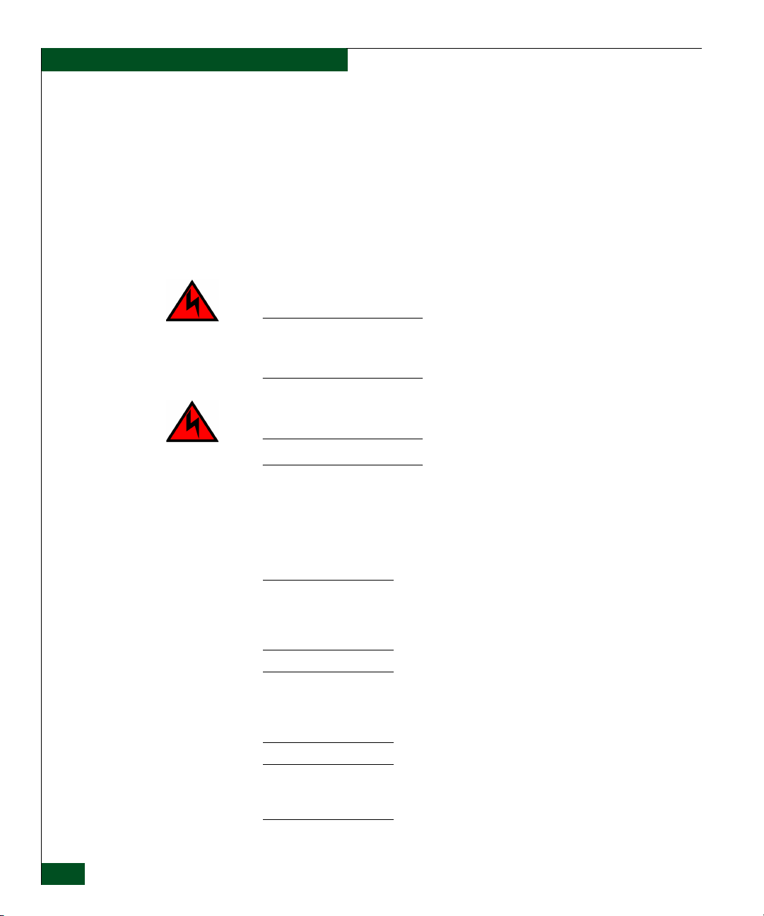
The switch provides a modular design that enables quick removal
and replacement of FRUs, including small form factor pluggable
(SFP) optical transceivers and power supply assemblies. Figure 1-1
illustrates the front of the switch and shows the:
1. RESET button.
2. Ethernet LAN connector.
3. Green power (PWR) light-emitting diode (LED).
4. Amber system error (ERR) LED.
5. SFP optical transceivers (16).
6. Chassis ground (GND) connector.
Page 29
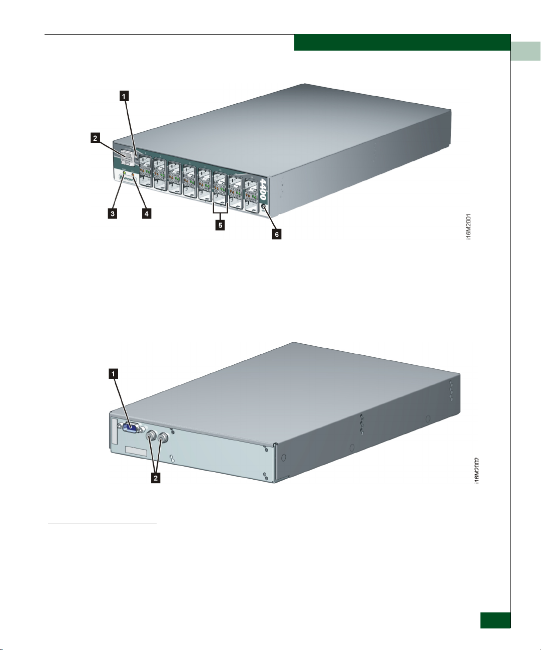
Figure 1-1 Sphereon 4400 Fabric Switch (Front View)
Figure 1-2 illustrates the rear of the switch and shows the:
1. RS-232 maintenance port.
2. External power supply connectors (2).
General Information
1
SFP Transceiver
Figure 1-2 Sphereon 4400 Fabric Switch (Rear View)
Multimode fiber-optic cables attach to switch ports through SFP
®
transceivers with duplex LC
connectors, and can be detached from
switch ports (through a 10-pin interface) for easy replacement.
Tri-rate (1.0625, 2.1250, or 4.2500 Gbps) shortwave laser transceivers
(850 nm) provide connectivity:
Switch Description
1-3
Page 30

General Information
1
• At 500 meters (1.0625 Gbps) through 50-micron multimode
fiber-optic cable.
• At 300 meters (2.1250 Gbps) through 50-micron multimode
fiber-optic cable.
• At 150 meters (4.2500 Gbps) through 50-micron multimode
fiber-optic cable.
• At 300 meters (1.0625 Gbps) through 62.5-micron multimode
fiber-optic cable.
• At 150 meters (2.1250 Gbps) through 62.5-micron multimode
fiber-optic cable.
• At 70 meters (4.2500 Gbps) through 62.5-micron multimode
fiber-optic cable.
Tri-rate longwave laser (1.0625, 2.1250, or 4.2500 Gbps) are also
available. Longwave laser transceivers provide connectivity at 4
kilometers and 10 kilometers through singlemode fiber-optic cable.
(Additional distances will be available in the future. 2Gb LW optics
are currently available for 10, 20, 35 and 80 kilometers.)
The switch also provides a predictive optics monitoring (POM)
feature that monitors operation of SFP optical transceivers. Digital
diagnostics-enabled optical transceivers report temperature, voltage
current, transceiver power, and receiver power to product firmware.
Optical transceivers also provide vendor-specific threshold values for
these parameters.
Power Supply Assembly
1-4
McDATA Sphereon 4400 Fabric Switch Installation and Service Manual
The switch is delivered with one external power supply assembly.
The power supply steps down and rectifies facility input power to
provide 12 volts direct current (VDC) to the control processor (CTP)
card. The power supply also provides input filtering, overvoltage
protection, and overcurrent protection. The power supply is input
rated at 100 to 240 volts alternating current (VAC).
A second power supply can be installed as an option. When a second
power supply is detected, the switch automatically enables high
availability (HA) mode. With HA mode enabled, either power supply
can be replaced while the switch is operational. Each power supply
has a separate connection to the CTP card to allow for independent
AC power sources.
Three internal cooling fans provide airflow for the CTP card, as well
as redundancy for continued operation if a single fan fails.
Page 31

Controls, Connectors, and Indicators
Controls, connectors, and indicators for the switch include the:
• RESET button.
• Ethernet LAN connector.
• Green PWR and amber ERR LEDs.
• Green and amber status LEDs associated with FRUs.
• RS-232 maintenance port.
• Chassis ground (GND) connector.
General Information
1
RESET Button
Ethernet LAN Connector
When the RESET button is pressed, held for three seconds, and
released, the switch performs an initial machine load (IML) that
reloads the firmware from FLASH memory. This operation is not
disruptive to Fibre Channel traffic. When the RESET button is
pressed and held for ten seconds, the switch performs a reset. After
three seconds, the ERR LED blinks at twice the unit beaconing rate. A
reset is disruptive to Fibre Channel traffic and resets the:
• Microprocessor and functional logic for the CTP card and reloads
the firmware from FLASH memory.
• Ethernet LAN interface, causing the connection to the
management server to drop momentarily until the connection
automatically recovers.
• Ports, causing all Fibre Channel connections to drop momentarily
until the connections automatically recover. This causes attached
devices to log out and log back in, therefore data frames lost
during switch reset must be retransmitted.
Perform a reset only if a CTP card failure is indicated. The button is
flush mounted to protect against inadvertent activation.
The front panel has a 10/100 megabit per second (Mbps) RJ-45
twisted-pair connector that attaches to an Ethernet LAN to provide
communication with a management server or simple network
management protocol (SNMP) workstation.
The connector provides two green LEDs. The left LED illuminates to
indicate LAN operation at 10 Mbps. The right LED illuminates to
indicate operation at 100 Mbps.
Controls, Connectors, and Indicators
1-5
Page 32

General Information
1
Power and System Error LEDs
FRU Status LEDs
Maintenance Port
The PWR LED illuminates when the switch is connected to facility
AC power and is operational (the product does not have a power
switch). If the LED extinguishes, a facility power source, power cord,
or power distribution failure is indicated.
The ERR LED illuminates when the switch detects an event requiring
operator attention, such as a FRU failure. The LED illuminates as
long as an event is active. The LED extinguishes when Clear System
Error Light is selected from the EFCM Basic Edition interface or
Element Manager application. The ERR LED also blinks if unit
beaconing is enabled. An illuminated LED (indicating a failure) takes
precedence over unit beaconing.
Amber and green LEDs associated with switch FRUs provide status
information as follows:
• Fibre Channel ports - LEDs above or below each port illuminate,
extinguish, or blink to indicate port status and speed. The amber
LED illuminates if the port fails. The green LED illuminates to
indicate 1.0625, 2.1250, or 4.2500 Gbps port operation.
• Power supply assembly - A green LED on each external
assembly illuminates when the FRU is operational.
The rear panel has a 9-pin DSUB maintenance port that provides a
connection for a local terminal or dial-in connection for a remote
terminal. The port is typically used only by maintenance personnel,
however operators can use the port to configure network addresses.
Chassis Ground Connector
Switch Specifications
1-6
McDATA Sphereon 4400 Fabric Switch Installation and Service Manual
The front panel has a chassis ground connector for an electrostatic
discharge (ESD) wrist strap and grounding cable. Plug the grounding
cable into the connector when performing a maintenance action with
the switch connected to facility power (grounded).
This section lists physical characteristics, storage and shipping
environment, operating environment, and service clearances.
Page 33

General Information
1
Physical
Characteristics
Dimensions:
Height: 4.1 centimeters (1.6 inches) or 1 rack unit
Width: 19.9 centimeters (7.8 inches)
Depth: 33.3 centimeters (13.1 inches), plus 6.1 centimeters
(2.4 inches) for external power supplies
Weig ht: 4.0 kilograms (8.8 pounds)
Power requirements:
Input voltage: 100 to 240 VAC
Input current: 3.5 amps at 208 VAC
Input frequency: 50 to 60 Hz
Heat dissipation:
42 watts (143 BTUs/hr)
Cooling airflow clearances (switch chassis):
Right and left side: 1.3 centimeters (0.5 inches)
Front and rear: 7.6 centimeters (3.0 inches)
Top and bottom: No clearance required
Shock and vibration tolerance:
Storage and Shipping
Environment
60 Gs for 10 milliseconds without nonrecoverable errors
Acoustical noise:
70 dB “A” scale
Inclination:
0
10
maximum
Protective packaging must be provided to protect the switch under
all shipping methods (domestic and international).
Shipping temperature:
0
-40
F to 1400 F (-400 C to 600 C)
Storage temperature:
0
34
F to 1400 F (10 C to 600 C)
Switch Specifications
1-7
Page 34

General Information
1
Shipping relative humidity:
5% to 100%
Storage relative humidity:
5% to 80%
Maximum wet-bulb temperature:
0
84
F (290 C)
Altitude:
40,000 feet (12,192 meters)
Operating
Environment
Temperature:
0
40
Relative humidity:
8% to 80%
Maximum wet-bulb temperature:
0
81
Altitude:
10,000 feet (3,048 meters)
Maintenance Approach
The maintenance approach instructs service personnel to perform
fault isolation and repair procedures without degrading or
interrupting product operation or associated applications. Fault
isolation begins when one or more of the following occur:
• Event information displays at a browser-capable PC
communicating with the product through the EFCM Basic
Edition interface.
• Event information displays at a LAN-connected PC or
workstation communicating with the rack-mount management
server running a SAN management application.
F to 1040 F (40 C to 400 C)
F (270 C)
1-8
• LEDs on the product front panel or FRUs illuminate to indicate a
hardware malfunction.
McDATA Sphereon 4400 Fabric Switch Installation and Service Manual
Page 35

• An unsolicited SNMP trap message is received at a management
• Event notification is received at a designated support center
Fault isolation and repair information is provided through
maintenance analysis procedures (MAPs). MAPs are step-by-step
procedures that provide information to interpret events, isolate a
failure to a FRU, remove and replace the FRU, and verify product
operation. Fault isolation begins with MAP 0000: Start MAP.
Switch Management
The switch is managed and controlled through a:
• Customer-supplied PC platform with Internet communication to
General Information
1
workstation, indicating an operational state change or failure.
through an e-mail message or the call-home feature.
the product-resident EFCM Basic Edition interface.
The interface allows service personnel to perform configuration
tasks, view system alerts and related log information, and
monitor switch status, port status, and performance. FRU status
and system alert information are highly visible.
Management Server
• Optional 1U management server (running a SAN management
application) that provides a central point of control for up to 48
switches or managed products.
The management server is delivered with server and client SAN
management applications and the Element Manager application
installed. A customer-supplied PC or workstation (with client
applications installed) communicates with the server through a
through a corporate intranet.
• Customer-supplied PC or UNIX-based platform with the server
and client SAN management and Element Manager applications
installed.
The management server is a 1U, rack-mount unit that provides a
central point of control for up to 48 connected switches or other
managed products. Server applications are accessed through a
LAN-attached PC or workstation with client software installed.
Figure 1-3 illustrates the server with attached liquid crystal display
(LCD) panel.
Switch Management
1-9
Page 36

General Information
1
Figure 1-3 Management Server
The server is rack mounted in the McDATA-supplied FC-512
Fabricenter equipment cabinet. A SANpilot interface or management
server is required to install, configure, and manage the switch.
The server provides two auto-detecting 10/100 Mbps Ethernet LAN
connectors (RJ-45 adapters). The first adapter (LAN 1) attaches
(optionally) to a public customer intranet to allow access from remote
user workstations. The second adapter (LAN 2) attaches to a private
LAN segment containing switches or managed products.
Management Server Specifications
Minimum
Specifications
This section summarizes minimum and recommended hardware
specifications for the rack-mount management server. Servers may
ship with more enhanced hardware, such as a faster processor,
additional random-access memory (RAM), or a higher-capacity hard
drive.
Minimum server specifications are:
®
• 1U rack-mount server running the Intel
Pentium® 4 processor
with a 2 gigahertz (GHz) or greater clock speed, using the
Microsoft Windows 2000 Professional (with service pack 4),
Windows XP Professional (with service pack 2), or Windows
Server 2003 operating system (Enterprise Edition with service
pack 1) operating system.
• TightVNC™ Viewer Version 1.2.7 client-server software control
package that provides remote network access (through a web
browser) to the management server desktop.
• 1,024 megabyte (MB) RAM.
• 40 gigabyte (GB) internal hard drive.
• 1.44 MB 3.5-inch slim-type disk drive.
1-10
McDATA Sphereon 4400 Fabric Switch Installation and Service Manual
Page 37

General Information
• 24X read speed slim-type compact disk-rewritable (CD-RW)
and 8X read speed digital video disk (DVD) combination drive,
data only.
• 56K peripheral component interconnect (PCI) internal data and
fax modem, using the V .92 dial-up specification.
• 16 MB graphics card.
• Network interface card (NIC) with two 10/100 Mbps Ethernet
adapters using RJ-45 connectors.
1
Recommended
Specifications
Recommended server specifications are:
• 1U rack-mount server running the Intel Pentium 4 processor with
a 3 GHz or greater clock speed, using an 800 megahertz (MHz)
front side bus, using the Microsoft Windows Server 2003
operating system (Enterprise Edition with service pack 1).
• TightVNC™ Viewer Version 1.2.7 client-server software control
package that provides remote network access (through a web
browser) to the management server desktop.
• 2,048 MB (or greater) double data-rate synchronous dynamic
random access memory (SDRAM).
• 40 GB (or greater) internal hard drive, with advanced technology
attachment (ATA-100) integrated drive electronics interface
operating at 7,200 rpm.
• 1.44 MB 3.5-inch slim-type disk drive.
• 48X read speed slim-type CD-RW and 32X read speed DVD
combination drive, data only.
• 56K PCI internal data and fax modem, using the V .92 dial-up
specification.
• Video graphics array (VGA) capable 32 MB graphics card.
• NIC with two 10/100 Mbps Ethernet adapters using RJ-45
connectors.
Ethernet Hub (Optional)
The management server and managed switches connect through a
10/100 Base-T Ethernet hub. Figure 1-4 illustrates the 24-port hub.
Switch Management
1-11
Page 38

General Information
1
.
Figure 1-4 24-Port Ethernet Hub
Hubs can be daisy-chained to provide additional connections as more
switches (or other McDATA managed products) are installed on a
network. Multiple hubs are daisy-chained by attaching RJ-45
Ethernet patch cables and configuring each hub through a mediumdependent interface (MDI) switch.
Error-Detection, Reporting, and Serviceability Features
1-12
The switch provides the following error detection, reporting, and
serviceability features:
• LEDs on switch FRUs and adjacent to Fibre Channel ports that
provide visual indicators of hardware status or malfunctions.
• Redundant FRUs (SFP transceivers and power supply
assemblies) that are removed or replaced without disrupting
switch or Fibre Channel link operation.
• A modular design that enables quick removal and replacement of
FRUs without the use of tools or equipment.
• System alerts and logs that display switch, Ethernet link, and
Fibre Channel link status at the EFCM Basic Edition interface,
client communicating with the management server, or customersupplied server (running a SAN management application).
• Diagnostic software that performs power-on self-tests (POSTs)
and port diagnostics (loopback tests).
McDATA Sphereon 4400 Fabric Switch Installation and Service Manual
Page 39

General Information
• An RS-232 maintenance port at the rear of the switch (port
access is password protected) that enables installation or service
personnel to change the switch’s IP address, subnet mask, and
gateway address.
These parameters can also be changed through a Telnet session,
access for which is provided through a local or remote PC with an
Internet connection to the switch.
• Data collection through the EFCM Basic Edition interface or
Element Manager application to help isolate system problems.
The data includes a memory dump file and audit, hardware, and
engineering logs.
• Beaconing to assist service personnel in locating a specific port or
switch. When port beaconing is enabled, the amber LED
associated with the port flashes. When unit beaconing is enabled,
the system error indicator on the front panel flashes. Beaconing
does not affect port or switch operation.
• An internal modem for use by support personnel to dial-in to the
management server (optional) for event notification and to
perform remote diagnostics.
1
• Automatic notification of significant system events (to support
personnel or administrators) through e-mail messages or the
call-home feature.
NOTE: The call-home feature is not available through the EFCM Basic
Edition. The call-home feature may not be available if the EFCM Lite
application is installed on a customer-supplied platform.
• SNMP management using the Fibre Channel Fabric Element MIB,
Transmission Control Protocol/Internet Protocol (TCP/IP)
MIB-II definition (RFC 1157), or a product-specific private
enterprise MIB that runs on the switch. Up to six authorized
management workstations can be configured through the EFCM
Basic Edition interface or Element Manager application to receive
unsolicited SNMP trap messages. The trap messages indicate
product operational state changes and failure conditions.
• Optional SNMP management using the Fibre Alliance MIB that
runs on the management server. Up to 12 authorized
management workstations can be configured through the SAN
Error-Detection, Reporting, and Serviceability Features
1-13
Page 40

General Information
1
management application to receive unsolicited SNMP trap
messages. The trap messages indicate operational state changes
and failure conditions.
Tools and Test Equipment
This section describes tools and test equipment that may be required
to install, test, service, and verify operation of the product and
attached management server. These tools are supplied with the
product or must be supplied by service personnel.
Tools Supplied with the Product
Figure 1-5 Door Key
The following tools are supplied with the product:
• Door key - A door key with 5/16-inch socket (Figure 1-5) is
required to open front and rear doors of the Fabricenter
Equipment Cabinet. A 5/16-inch socket wrench may also be used.
• Loopback plug - A multimode (shortwave laser) loopback plug
(Figure 1-6) is required to perform port diagnostic tests. Loopback
plugs are shipped with the product, depending on the types of
port transceivers installed.
1-14
Figure 1-6 Loopback Plug
McDATA Sphereon 4400 Fabric Switch Installation and Service Manual
Page 41

• Fiber-optic protective plug - For safety and port transceiver
protection, fiber-optic protective plugs (Figure 1-7) are inserted in
all product ports without fiber-optic cables attached. Products are
shipped with protective plugs installed.
Figure 1-7 Fiber-Optic Protective Plug
• Null modem cable - An asynchronous RS-232 null modem cable
(Figure 1-8) is required to configure product network addresses
and acquire event log information through the product’s serial
port. The cable has nine conductors and DB-9 female connectors.
General Information
1
Figure 1-8 Null Modem Cable
Tools Supplied by Service Personnel
The following tools should be supplied by service personnel:
• Scissors or pocket knife - A sharp cutting edge (scissors or knife
blade) is required to cut protective strapping when unpacking
replacement FRUs.
• Flat-tip and cross-tip (Phillips) screwdrivers - Screwdrivers are
required to remove, replace, adjust, or tighten FRUs, chassis, or
cabinet components.
Tools and Tes t Equipme nt
1-15
Page 42

General Information
1
• T10 Torx® tool - The tool is required to rack-mount products or to
remove, replace, adjust, or tighten chassis or cabinet components.
• ESD grounding cable and wrist strap - An ESD wrist strap is
required when working with ESD-sensitive FRUs, including
optical transceivers.
• Maintenance terminal - A desktop or notebook PC is required to
configure product network addresses and acquire event log
information through the maintenance port. The PC must have:
— The Microsoft® Windows® 98, Windows® 2000, Windows®
2003, Windows® XP, or Windows® ME operating system
installed.
— RS-232 serial communication software (such as ProComm
Plus™ or HyperTerminal) installed. HyperTerminal is
provided with Windows operating systems.
• Fiber-optic cleaning kit - The kit contains tools and instructions
to clean fiber-optic cables, connectors, loopback plugs, and
protective plugs.
1-16
McDATA Sphereon 4400 Fabric Switch Installation and Service Manual
Page 43

Factory Defaults
2
Installation Tasks
This chapter describes tasks to install, configure, and verify operation
of the Sphereon 4400 Fabric Switch using the EFCM Basic Edition
interface or storage area network (SAN) management application.
The product can be installed on a table top, mounted in a Fabricenter
equipment cabinet, or mounted in any standard 19-inch equipment
rack.
Ta bl e 2 -1 lists factory-set defaults for the product.
Table 2-1 Factory-Set Defaults (Product)
Item Default
EFCM Basic Edition interface user name (case sensitive) Administrator
EFCM Basic Edition interface password (case sensitive) password
Customer-level password (maintenance port access) password
Maintenance-level password (maintenance port access) level-2
IP address 10.1.1.10
Subnet mask 255.0.0.0
Gateway address 0.0.0.0
Factory Defaults
2-1
Page 44

Installation Tasks
2
Tabl e 2-2 lists factory-set defaults for the rack-mount management
server (running a SAN management application).
Table 2-2 Factory-Set Defaults (Management Server)
Item Default
Liquid crystal display (LCD) front panel 9999
Windows operating system user name (case sensitive) Administrator
Windows operating system password (case sensitive) password
SAN management application user name (case sensitive) Administrator
SAN management application password (case sensitive) password
LAN 1 (public interface) IP address 192.168.0.1
Subnet mask 255.0.0.0
Gateway address 0.0.0.0
LAN 2 (private interface) IP address 10.1.1.1
Subnet mask 255.0.0.0
Gateway address 0.0.0.0
Installation Task Summary
Tabl e 2-3 summarizes installation tasks for the product, optional
management server, and optional Ethernet hub. The table describes
each task, states if the task is optional, and lists the page reference.
Table 2-3 Installation Task Summary
Task Number and Description Required or Optional Page
Task 1: Verify Installation Requirements Required. 2-4
Task 2: Unpack, Inspect, and Install the Ethernet Hub
(Optional)
Task 3: Unpack, Inspect, and Install the Product Required. 2-9
Task 4: Configure Product at the EFCM Basic Edition
Interface (Optional)
2-2
McDATA Sphereon 4400 Fabric Switch Installation and Service Manual
Perform task if hub is required to connect switch and
management interface.
Perform task if switch is managed through the EFCM
Basic Edition interface.
2-5
2-12
Page 45

Installation Tasks
Table 2-3 Installation Task Summary (continued)
Task Number and Description Required or Optional Page
2
Task 5: Configure Product Network Information (Optional) Configure if connecting multiple switches or connecting
2-32
switch and management server to a public LAN.
Task 6: Unpack, Inspect, and Install the Management Server Required if management server is used. 2-35
Task 7: Configure Server Password and Network Addresses Required if management server is used. 2-38
Task 8: Configure Management Server Information Required if management server is used. 2-40
Task 9: Configure Windows Operating System Users Required if management server is used. 2-44
Task 10: Set Management Server Date and Time Required if management server is used. 2-46
Task 11: Configure the Call-Home Feature (Optional) Configure if specified by customer and telephone
2-48
connection is provided.
Task 12: Assign User Names and Passwords Required if management server is used. 2-49
Task 13: Configure the Product to the Management
Required if management server is used. 2-51
Application
Task 14: Record or Verify Server Restore Information Required if management server is used. 2-52
Task 15: Verify Product-to-Server Communication Required if management server is used. 2-53
Task 16: Configure PFE Key (Optional) Configure if product feature enablement (PFE) key is
2-55
ordered.
Task 17: Configure Management Server (Optional) Configure for open-systems host control of switch. 2-56
Task 18: Set Product Date and Time Required if management server is used. 2-57
Task 19: Configure the Element Manager Application Required if management server is used. 2-59
Task 20: Back Up Configuration Data Required if management server is used. 2-75
Task 21: Cable Fibre Channel Ports Required. 2-77
Task 22: Configure Zoning (Optional) Perform task to configure zoning. 2-78
Task 23: Connect Product to a Fabric Element (Optional) Perform task to connect switch to a Fibre channel fabric. 2-79
Task 24: Register with the McDATA Filecenter Required. 2-80
Installation Task Summary
2-3
Page 46

Installation Tasks
2
Task 1: Verify Installation Requirements
Ensure that the following requirements are met prior to product and
management interface installation. Ensure:
• A site plan is prepared, configuration planning tasks are
complete, planning considerations are evaluated, and related
planning checklists are complete. Refer to McDATA Products in a
SAN Environment - Planning Manual (620-000124) for information.
• Fibre Channel SAN design and director, fabric switch, and SAN
router device connectivity are evaluated, and the related
planning worksheet is complete. Refer to the McDATA Products in
a SAN Environment - Planning Manual (620-000124) for
information.
• Support is available for one of the following product
management methods:
— A browser-capable PC and Internet connectivity to support
the product-resident EFCM Basic Edition interface, or
— A rack-mount management server or browser-capable PC and
LAN segment connectivity to support operation of SAN
management and Element Manager applications.
2-4
• Support equipment and technical personnel are available for the
installation.
• The required number and type of fiber-optic jumper cables are
delivered and available. Ensure that the cables are of the correct
length and have the required connectors.
• A Fabricenter cabinet or customer-supplied 19-inch equipment
rack and associated hardware are available (optional).
• Remote workstations or simple network management protocol
(SNMP) workstations are available (optional).
• Workstations are customer-supplied and connected through a
public or dedicated LAN segment.
McDATA Sphereon 4400 Fabric Switch Installation and Service Manual
Page 47

Installation Tasks
Task 2: Unpack, Inspect, and Install the Ethernet Hub (Optional)
This section describes how to unpack, inspect and install the theernet
hub.
The product is managed through either:
• An Internet connection to a browser-capable PC (EFCM Basic
Edition interface). Connection of a LAN segment with multiple
switches to the Internet may require installation of a 24-port
Ethernet hub.
• A 10/100 megabit per second (Mbps) LAN connection to a
management server. Connectivity may require installation of a
24-port Ethernet hub. A combination of up to 48 products can be
configured and managed on one network, therefore multiple,
daisy-chained hubs may be required to provide sufficient port
connections.
The following paragraphs provide instructions to unpack, inspect,
and install one or more Ethernet hubs.
• If the existing Ethernet LAN segment is adequate for connectivity
and a hub is not delivered, this task is not required. Go to Tas k 3:
Unpack, Inspect, and Install the Product.
2
Unpack and Inspect Ethernet Hub
• If the hub is delivered in a Fabricenter equipment cabinet, go to
Task 5: Configure Product Network Information (Optional).
To unpack and inspect Ethernet hub(s) use the following steps:
1. Inspect shipping container(s) for damage. Ensure a freight carrier
representative is present when the container is opened. Unpack
shipping container(s) and inspect each item for damage. Ensure
that the packaged items correspond to items listed on the
enclosed bill of materials.
2. Contact the solution center if items are damaged or missing,:
Phone: (800) 752-4572 or (720) 558-3910
Fax: (720) 558-3851
E-mail: support@mcdata.com
Task 2: Unpack, Inspect, and Install the Ethernet Hub (Optional)
2-5
Page 48

Installation Tasks
2
Desktop Installation
To install and configure up to three Ethernet hubs on a desktop, use
the following steps:
1. Remove the backing from the four adhesive rubber pads and
apply the pads to the underside of each hub. Ensure that the pads
are aligned with the scribed circles at each corner.
2. Position the first hub on a table or desktop as directed by the
customer.
3. Stack the remaining hubs on top of the first hub. Ensure that the
adhesive rubber pads on the underside of a hub align with the
recesses on the top of the hub below.
4. Daisy-chain (connect) the hubs using the following steps:
a. Connect the top and middle stacked hubs, connect an RJ-45
patch cable to port 24 of the top hub, then connect the cable to
port 12 of the middle hub.
b. Connect the bottom and middle stacked hubs, connect a
second RJ-45 patch cable to port 24 of the middle hub, then
connect the cable to port 12 of the bottom hub.
c. Use a pointed instrument to set the medium-dependent
interface (MDI) switch on the top and middle hubs to MDI
(in) as shown in Figure 2-1 (1 and 2).
d. Set the medium-dependant interface (MDI) switch on the
bottom hub to MDIX (out) as shown in Figure 2-1 (3).
2-6
NOTE: To connect two hubs, use step b and step c (middle and
bottom hub instructions only).
McDATA Sphereon 4400 Fabric Switch Installation and Service Manual
Page 49

Figure 2-1 Patch Cable and MDI Selector Configuration
5. Connect a power cord to an AC power strip and the receptacle at
the rear of each hub. Use an extension cord if required.
Installation Tasks
2
Rack-Mount Installation
6. Connect the AC power strip to facility power. Power for each hub
switches on when the strip is connected to facility AC power.
7. Inspect the front panel of each hub. Ensure that each green Power
light-emitting diode (LED) illuminates.
You will need a pointed instrument (pencil tip or bent paper clip), #2
Phillips screwdriver, and 1/8-inch Allen wrench for this procedure.
To install and configure up to three Ethernet hubs in a Fabricenter
cabinet or customer-supplied 19-inch equipment rack, use the
following steps
1. Secure one mounting bracket to each side of the first hub as
shown in Figure 2-2. Use the two brackets and four pan-head
Phillips screws (8/32 x 0.5-inch) provided.
Task 2: Unpack, Inspect, and Install the Ethernet Hub (Optional)
2-7
Page 50

Installation Tasks
2
Figure 2-2 Mounting Bracket Installation (Ethernet Hub)
2. Position the hub as directed by the customer. Align screw holes in
the mounting brackets with screw holes in the rack-mount
standards.
3. Secure both sides of the hub to the rack-mount standards. Use the
1/8-inch Allen wrench and four Allen-head mounting screws
(10/32 x 0.5-inch) provided.
2-8
4. Repeat step 1 through step 3 for the remaining hubs.
5. Daisy-chain (connect) the hubs using the following procedure:
a. Connect the top and middle stacked hubs, connect an RJ-45
patch cable to port 24 of the top hub, then connect the cable to
port 12 of the middle hub.
b. Connect the bottom and middle stacked hubs, connect a
second RJ-45 patch cable to port 24 of the middle hub, then
connect the cable to port 12 of the bottom hub.
c. Use a pointed instrument Figure 2-1 (1 and 2), to set the
medium-dependent interface (MDI) switch on the top and
middle hubs to MDI (in). As shown in Figure 2-1 (3), set the
MDI switch on the bottom hub to MDIX (out).
NOTE: To connect two hubs follow the middle and bottom hub
instructions only.
6. Connect a power cord to a rack power strip and the receptacle at
the rear of each hub. Power for each hub switches on when the
hub (and equipment rack) are connected to facility AC power.
McDATA Sphereon 4400 Fabric Switch Installation and Service Manual
Page 51

NOTE: Ensure each hub is connected to a separate rack power strip.
7. Inspect the front panel of each hub. Ensure each green Power
LED illuminates.
Task 3: Unpack, Inspect, and Install the Product
Follow the procedures in this section to unpack, inspect, and install
one or more switches. If the switch is delivered in a Fabricenter
equipment cabinet, go to Task 5: Configure Product Network Information
(Optional).
Installation Tasks
2
Unpack and Inspect Switch
Desktop Installation
To unpack and inspect switch(es), use the following steps:
1. Inspect shipping container(s) for damage. Ensure that a freight
carrier representative is present when the container is opened.
Unpack shipping container(s) and inspect each item for damage.
Ensure that the packaged items correspond to items listed on the
enclosed bill of materials.
2. Contact the technical support center if any tems are damaged or
missing,:
Phone: (800) 752-4572 or (720) 558-3910
Fax: (720) 558-3851
E-mail: support@mcdata.com
To install a switch on a desktop, use the following steps:
1. Remove the backing from the three adhesive rubber pads and
apply the pads to the underside of the switch. Ensure pads are
aligned with the scribed circles.
2. Position the switch on a table or desktop as directed by the
customer. Ensure:
— Grounded AC electrical outlets are available.
— Adequate ventilation is present, and areas with excessive heat,
dust, or moisture are avoided.
Task 3: Unpack, Inspect, and Install the Product
2-9
Page 52

Installation Tasks
2
— All planning considerations are met. Refer to McDATA
Products in a SAN Environment - Planning Manual (620-000124)
for information.
3. Ensure that all field-replaceable units (FRUs) are installed as
ordered.
4. Connect power supply adapter cords to threaded output jacks at
the rear of the chassis (second external power supply is optional).
Twist the cord clockwise to lock and secure the connection.
5. Connect AC power cords to connectors on each external power
supply and to separate (for redundancy) facility power sources
that provide single-phase, 100 to 240 volt alternating current
(VAC) current.
When the first power cord is connected, the switch powers on
and performs power-on self-tests (POSTs). During POSTs:
a. The green power (PWR) LED on the front panel illuminates.
b. The amber system error (ERR) LED on the front panel blinks
momentarily while the switch is tested.
c. The green LED associated with the Ethernet port blinks
momentarily while the port is tested.
2-10
d. LEDs associated with Fibre Channel ports blink momentarily
while the ports are tested.
After successful POST completion, the PWR LED remains
illuminated and all other front panel LEDs extinguish.
If a POST error or other malfunction occurs, go to MAP 0000: Start
MAP to isolate the problem.
6. Perform one of the following:
— If the switch is to be managed through the EFCM Basic Edition
interface, go to Task 4: Configure Product at the EFCM Basic
Edition Interface (Optional).
— If the switch is to be managed through a management or
customer-supplied server, go to Task 5: Configure Product
Network Information (Optional).
McDATA Sphereon 4400 Fabric Switch Installation and Service Manual
Page 53

Installation Tasks
2
Rack-Mount Installation
You will need an optional rack-mount kit, T10 Torx tool, and #2
Phillips screwdriver for this procedure.
To install and configure the switch in a Fabricenter cabinet or a
customer-supplied equipment rack, use the following steps:
1. Locate the rack-mount position as directed by the customer. The
switch is 1.75 inches, or 1U high.
2. Ensure that all FRUs are installed as ordered.
3. Open the rack-mount kit and inspect the contents. Refer to the
enclosed bill of materials and verify all parts are delivered.
4. Install the switch and optional slide tray (holds two switches) in
the equipment cabinet. Refer to McDATA Sphereon 4400 Switch
Rack-Mount Kit Installation Instructions (958-000480) for guidance.
5. Connect power supply adapter cords to threaded output jacks at
the rear of the chassis (second external power supply is optional).
Twist the cord clockwise to lock and secure the connection.
6. Connect AC power cords to connectors on each external power
supply and to separate (for redundancy) rack power strips
connected to a facility power source that provides single-phase,
100 to 240 VAC current.
When the first power cord is connected, the switch powers on
and performs POSTs. During POSTs:
a. The green power (PWR) LED on the front panel illuminates.
b. The amber system error (ERR) LED on the front panel blinks
momentarily while the switch is tested.
c. The green LED associated with the Ethernet port blinks
momentarily while the port is tested.
d. LEDs associated with Fibre Channel ports blink momentarily
while the ports are tested.
After successful POST completion, the PWR LED remains
illuminated and all other front panel LEDs extinguish.
If a POST error or other malfunction occurs, go to MAP 0000: Start
MAP to isolate the problem.
7. Perform one of the following:
Task 3: Unpack, Inspect, and Install the Product
2-11
Page 54

Installation Tasks
2
— If the switch is to be managed through the EFCM Basic Edition
interface, go to Task 4: Configure Product at the EFCM Basic
Edition Interface (Optional).
— If the switch is to be managed through a management or
customer-supplied server, go to Task 5: Configure Product
Network Information (Optional).
Task 4: Configure Product at the EFCM Basic Edition Interface (Optional)
Follow the procedures in this section to configure the product from
the EFCM Basic Edition interface. A browser-capable PC with
Internet or Ethernet LAN access is required. To open the interface,
use the following steps:
1. Connect the Ethernet patch cable (supplied with the product) to
the RJ-45 connector (labelled 10/100) at the front panel.
2. Connect the remaining end of the Ethernet cable to the Internet or
LAN segment as directed by the customer. If the hub installed in
Task 2: Unpack, Inspect, and Install the Ethernet Hub (Optional)
provides connectivity, connect the cable to any available hub port.
3. Open the browser application (Netscape Navigator
Explorer).
or Internet
2-12
4. Enter the default Internet Protocol (IP) address of the switch
(10.1.1.10). The Enter Network Password dialog box appears.
5. Type the case-sensitive default user name (Administrator) and
password (password) and click OK. The First Time Login View
appears.
6. Type customer-specified values in the User Name, New Password,
and Confirm Password fields, then click Activate. The Topology View
appears with status information about each fabric element,
including the product to be configured.
7. Click Switch Details. The Hardware View appears (Figure 2-3).
McDATA Sphereon 4400 Fabric Switch Installation and Service Manual
Page 55

Installation Tasks
2
Figure 2-3 Hardware View
8. S electively perform the following tasks to configure the product
from the EFCM Basic Edition interface, according to customer
requirements:
Product • Identification
• Date and time
• Parameters
• Fabric parameters
• Network addresses.
Ports • Basic information
• Buffer-to-buffer credits (BB_Credits)
• N_Port identifier virtualization (NPIV).
Management • SNMP trap message recipients
• Command line interface (CLI)
• Open systems management server (OSMS)
• Secure socket layer (SSL) encryption.
Task 4: Configure Product at the EFCM Basic Edition Interface (Optional)
2-13
Page 56

Installation Tasks
2
Options Product feature enablement (PFE) keys.
Security • SANtegrity authentication (settings, access control list, and remote authentication
Interswitch Links • OpenTrunking
Configure Product Identification
dial-in user service (RADIUS) server support),
• Enterprise Fabric Mode
• SANtegrity binding (fabric, switch, and port binding
• Preferred path, and
• Interswitch link (ISL) port fencing
Follow the procedures in this section to configure the product
identification.
NOTE: The Name, Location, and Contact variables correspond respectively to
the SNMP variables sysName, sysLocation, and sysContact, and are used by
management workstations when obtaining product data.
1. Select Identification from the Configure menu
(Configure>Switch>Identification). The Identification View appears
(Figure 2-4).
2-14
Figure 2-4 Identification View
a. Type a unique product name of 24 alphanumeric characters or
less in the Name field. If installed on a public LAN, the name
should reflect the product’s Ethernet network domain name
system (DNS) host name.
McDATA Sphereon 4400 Fabric Switch Installation and Service Manual
Page 57

b. Type a product description of 255 alphanumeric characters or
less in the Description field.
c. Type the product’s physical location (255 alphanumeric
characters or less) in the Location field.
d. Type the name of a contact person (255 alphanumeric
characters or less) in the Contact field.
2. Click OK to save and activate changes.
Installation Tasks
2
Configure Date and Time
Figure 2-5 Date Time View
To configure product date and time, use the following steps:
1. Select Date & Time from the Configure menu
(Configure>Switch>Date & Time). The Date Time View appears
(Figure 2-5).
a. Configure the Date using the Date field:
•Month (MM): 1 - 12.
•Day (DD): 1 - 31.
•Year (YYYY): greater than 1980.
b. Configure the Time using the Date field:
•Hour (HH): 0 -23.
•Minute (MM): 0 - 59.
•Second (SS): 0 - 59.
2. Click OK to save and activate changes.
Task 4: Configure Product at the EFCM Basic Edition Interface (Optional)
2-15
Page 58

Installation Tasks
2
Configure Parameters
To configure product operating parameters, use the following steps:
1. Set the product offline. Refer to Setting Online State for
instructions.
2. Select Parameters from the Configure menu
(Configure>Switch>Parameters). The Parameters View appears
(Figure 2-6).
a. Select the Domain ID Offset value from the drop-down list.
Values available in the drop-down list are 0, 32, 64, 96
(default), 128, 160, and 192. Domain IDs minus the offset are
still in the 1-31 range.
2-16
Figure 2-6 Parameters View
b. Type a value (1-31) in the Preferred Domain ID field.
c. Enable (check) the Insistent Domain ID field if you want the
Preferred Domain ID to become the active domain ID when the
fabric initializes.
d. Enable (check) the Rerouting Delay field if you want the traffic
to be delayed through the fabric by the error detect time out
value (E_D_TOV). This delay ensures that the Fibre Channel
frames are delivered to their destination in order.
McDATA Sphereon 4400 Fabric Switch Installation and Service Manual
Page 59

e. Enable (check) the Domain RSCN field, if you want the
attached devices to register and receive notification when
other devices change state.
f. Enable (check) the Suppress RSCN on Zone Set Activations if you
do not want the RSCNs to be transmitted when a zone set is
activated.
g. Enable (check) the Isolate on zone activations field if you want
only devices that require RSCN notification due to a zoning
configuration change to receive RSCNs. Do not enable this
option if Suppress on zone set activations is enabled because
RSCNs will not be sent to attached devices.
h. Enable (check) the Limited Fabric RSCN field if you do not
want the RSCNs to be transmitted after a switch initial
program load (IPL).
i. Enable (check) the Node port virtualization to assign multiple
Fibre Channel addresses to a single N_Port port.
3. Click OK to save and activate changes.
4. Set the product online. Refer to Setting Online State for
instructions.
Installation Tasks
2
Configure Fabric Parameters
To configure fabric operating parameters, use the following steps.
1. Set the product offline. Refer to Setting Online State for
instructions.
2. Select Fabric Parameters from the Configure menu
(Configure>Switch>Fabric Parameters). The Fabric Parameters View
appears (Figure 2-7).
Task 4: Configure Product at the EFCM Basic Edition Interface (Optional)
2-17
Page 60

Installation Tasks
2
Figure 2-7 Fabric Parameters View
a. Type a value between 10 - 1200 tenths of a second (1 - 120
seconds) in the R_A_TOV field. Ten seconds (100) is the
recommended value. The R_A_TOV value must exceed the
E_D_TOV value.
b. Type a value between 2 - 600 tenths of a second (0.2 - 60
seconds) at the E_D_TOV field. Two seconds (20) is the
recommended value.
2-18
NOTE: Fabric elements must be set to the same R_A_TOV and
E_D_TOV values. An ISL between fabric elements with different
values segments and prevents communication.
c. Select from the Switch Priority drop-down list to designate the
fabric’s principal switch. The principal switch is assigned a
priority of 1 and controls the allocation and distribution of
domain IDs for all fabric elements (including itself). Available
selections are Default, Principal, and Never Principal.
Principal is the highest priority setting, Default is next, and
Never Principal is the lowest. At least one switch in a fabric
must be set as Principal or Default. If all switches are set to
Never Principal, all ISLs segment.
d. Select from the Interop Mode drop-down list to set the product
operating mode. This setting affects the management mode
and does not affect port operation. Available selections are:
McDATA Sphereon 4400 Fabric Switch Installation and Service Manual
Page 61

• McDATA Fabric 1.0 - Select this option if the product is
fabric-attached only to other McDATA directors or
switches operating in McDATA fabric mode.
• Open Fabric 1.0 - Select this option (default) for managing
heterogeneous fabrics and if the product is fabric-attached
to McDATA directors or switches and other open-fabric
compliant switches.
NOTE: With Open Fabric 1.0 enabled, the default zone set is
disabled.
e. Select from the ISL Cost Configuration drop-down list, to select
By Port Speed or Ignore Port Speed to calculate fabric shortest
path first (FSPF) cost.
3. Click OK to save and activate changes.
4. Set the product online. Refer to Setting Online State for
instructions.
Installation Tasks
2
Configure Network Information
Follow the procedure in this section to configure the network
information.
Ensure the LAN installation with the network administrator:
• If one product is installed on a dedicated LAN, network
information (IP address, subnet mask, and gateway address) does
not require any change.
• Multiple products are installed or a public LAN segment is used,
network information must be changed to conform to the LAN
addressing scheme.
To change product network information, use the following steps:
1. Select Network from the Configure menu
(Configure>Switch>Network). The Network View appears
(Figure 2-8).
Task 4: Configure Product at the EFCM Basic Edition Interface (Optional)
2-19
Page 62

Installation Tasks
2
Figure 2-8 Network View
a. Type a value in the IP Address field (default is 10.1.1.10).
b. Type a value in the Subnet Mask field (default is 255.0.0.0).
c. Type a value in the Gateway Address field (default is 0.0.0.0).
2-20
2. Click OK to save and activate changes.
An acknowledgement message appears, indicating the browser
PC must be directed to the new IP address.
3. Update the address resolution protocol (ARP) table for the
browser PC.
a. Close the EFCM Basic Edition interface and all browser
applications.
b. Open the command prompt (DOS) on your Windows desktop.
c. Delete the switch’s old IP address from the ARP table. At the
command (C:\) prompt, type arp -d xxx.xxx.xxx.xxx, where
xxx.xxx.xxx.xxx is the old IP address for the switch.
d. Close the command prompt window and return to the
Windows desktop.
4. Perform a power-on reset (POR) (IML or Reset Switch).
5. Open the browser (Internet Explorer or Netscape Navigator) on
your PC. Enter the new IP address of the product as the URL. The
Enter Network Password dialog box appears.
McDATA Sphereon 4400 Fabric Switch Installation and Service Manual
Page 63

Installation Tasks
6. Type the case-sensitive user name and password and click OK.
The EFCM Basic Edition interface appears with the Topology View
displaying the status information about each fabric element.
2
Configure Basic Port Information
To configure basic port information, use the following steps:
1. Select Basic Info from the Configure menu (Configure>Ports>Basic
Info). The Basic Information View appears(Figure 2-9).
a. Type a port name (24 alphanumeric characters or less) for each
port to be configured in the Name field. The port name should
characterize the device to which the port is attached.
b. Enable the check box in the Blocked column if you want to
block a port (default is unblocked).
c. Disable the check box in the Fabric Address Notify column if
you want to disable the feature (default is enabled). When
enabled, an FL_Port transmits FAN frames after loop
initialization to ensure that FC-AL devices are still logged in.
Figure 2-9 Basic Information View
Task 4: Configure Product at the EFCM Basic Edition Interface (Optional)
2-21
Page 64

Installation Tasks
2
d. Select an option from the drop-down list in the Port Type
column to configure the port type. The available options are
fabric port (F), expansion port (E), generic port (G), generic
mixed port (GX), and fabric mixed port (FX).
e. Select an option from the drop-down list in the Speed (Gb/s)
column to configure the port transmission rate. The available
options are auto-negotiate between speeds (Negotiate), 1.0625
gigabit per second (Gbps) operation (1 Gb/sec), 2.1250 Gbps
operation (2 Gb/sec), and 4.2500 Gbps operation (4 Gb/sec).
2. Click OK to save and activate changes.
Configure Port BB_Credit
Configure Port NPIV
Follow the procedure in this section to configure a port to receive
BB_Credit.
The switch provides a port buffer pool of 150 receive BB_Credits.
Each port can be assigned between two and 120 credits, provided the
total credits allocated to all ports does not exceed 150. The default
value is six credits per port.
To configure ports to receive BB_Credit, use the following steps:
1. Set all or a subset of user-specified ports offline. Refer to Setting
Online State or Blocking or Unblocking a Port for instructions.
2. Select Ports and RX BB_Credit from the Configure menu at any
view. The RX BB_Credit View appears.
3. Perform one of the following:
— To set all offline ports to default values, click Default.
— To set an offline port to a user-specified value, type the
desired value in the RX BB_Credit column.
4. Click OK to save and activate changes.
5. Set ports online. Refer to Setting Online State (all) or Blocking or
Unblocking a Port (specified ports) for instructions.
NPIV allows multiple (up to 256) Fibre Channel addresses to be
assigned to a node (N_Port). The NPIV feature must be installed.
Refer to Installing PFE Keys (Optional) for instructions.
2-22
To configure port NPIV, use the following steps:
McDATA Sphereon 4400 Fabric Switch Installation and Service Manual
Page 65

Installation Tasks
1. Select NPIV from the Configure menu (Configure>Ports>NPIV).
The NPIV View appears.
2. Click Enable to activate NPIV operation for the product.
3. Type a desired value(1 through 256) in the Login column.
4. Click OK to save and activate changes.
2
Configure SNMP
Follow the procedure in this section to configure names, write
authorizations, addresses, and user datagram protocol (UDP) port
numbers for SNMP trap message recipients.
To configure recipient workstations, use the following steps:
1. Select SNMP from the Configure menu (Configure>SNMP). The
SNMP View appears (Figure 2-10).
a. Click Enable to activate the installed SNMP agent.
b. Select the appropriate Fibre Alliance management information
base (FA MIB) from the FA MIB Version drop-down list. Valid
selections are FA MIB Version 3.0 or FA MIB Version 3.1.
Figure 2-10 SNMP View
c. Check the Enable Authentication Traps check box to enable
transmission of SNMP trap messages to recipients.
Task 4: Configure Product at the EFCM Basic Edition Interface (Optional)
2-23
Page 66

Installation Tasks
2
d. Type a community name, for each configured recipient (32
alphanumeric characters or less) in the Name field. The name is
incorporated in SNMP trap messages to ensure against
unauthorized viewing.
e. Check the box in the Write Auth column to enable write
authorization for the trap recipient (default is disabled). When
enabled, a configured user can change sysContact, sysName,
and sysLocation SNMP variables.
f. Type the IP address or DNS host name of the trap recipient
(SNMP management workstation) in the Trap Rec ipi e nt field. It
is recommended that the IP address be used.
g. Type a decimal port number in the UDP Port Number field to
specify the UDP port number.
2. Click OK to save and activate changes.
Enable CLI
Enable or Disable the CLI for SSH
Follow the procedure in this section to toggle (enable or disable) the
state of the product’s command line interface. To change the CLI
state, Enable the check box Enable CLI from the Configure menu
To configure SSH, Select Configure > SSH on the navigation panel.
The SSH configuration page (Figure 2-11) appears.
2-24
Figure 2-11 SSH Configuration
McDATA Sphereon 4400 Fabric Switch Installation and Service Manual
Page 67

Installation Tasks
Click Enable to enable SSH. Click Disable to disable the SSH. When
SSH is enabled, only SSH is allowed, and all data sent over the
connection is encrypted. When the SSH is disabled, only Telnet is
allowed, and the data is not encrypted.
2
Enable or Disable Host Control
Figure 2-12 OSMS View
Folllow the procedure in this section to configure the open systems
management server and enable OSI host control of the product.
Implementing and enabling OSI host control requires installation of a
SAN management application on the OSI server. Applications
®
include Veritas
SANPoint™ Control or Tivoli® NetView®.
To enable or disable OSMS host control:, use the following steps
1. Select OSMS from the Configure menu (Configure>OSMS). The
OSMS View appears (Figure 2-12).
2. Perform one of the following:
• Click Enable to activate OSMS.
Configure SSL Encryption
• Click Disable to deactivate OSMS.
3. Click the Enable Host Control check box to activate host control of
the product.
4. Click OK to save and activate changes.
SSL is a protocol that encrypts internet communications. The protocol
uses key encryption and includes a digital certificate that enables
server authentication and SSL session initialization.
To configure SSL encryption, use the following steps:
Task 4: Configure Product at the EFCM Basic Edition Interface (Optional)
2-25
Page 68

Installation Tasks
2
1. Select SSL from the Configure menu (Configure>SSL). The SSL
View appears (Figure 2-13).
2. Perform one of the following:
• Click Enable to activate web SSL.
• Click Disable to deactivate web SSL.
3. Perform one of the following:
• Click Enable to activate software SSL.
• Click Disable to deactivate software SSL.
2-26
Figure 2-13 SSL View
4. Type a value between 30 and 3650 in the Expires in field to define
the expiration period (in days) of the digital certificate. The
default is 365 days.
5. Click Generate to generate a new certificate.
6. Type a value between 50 and 10000 in the Renegotiate after field to
define a renegotiation parameter (in megabytes) for the SSL
session key.
7. Click OK to save and activate changes.
McDATA Sphereon 4400 Fabric Switch Installation and Service Manual
Page 69

Installation Tasks
2
Installing PFE Keys (Optional)
Follow the procedures in this section to install optional features using
PFE keys.
After purchasing a feature, you must obtain the PFE key by following
the enclosed instructions. The key is an alphanumeric string
consisting of uppercase and lowercase characters that must be
entered exactly, including dashes. An example format is:
XxXx-XXxX-xxXX-xX.
Keys are encoded to work only with the serial number of the installed
product. Note down the key. This will help you to re-install the
feature when required.
If the product fails and is replaced, obtain new PFE keys from the
technical support center (800-752-4572 or support@mcdata.com). You
will have to provide the serial numbers of the failed and replacement
products, and the old PFE key number or transaction code.
The optional features you can install using PFE-keys are listed below:
• Element Manager application - This feature enables out-of-band
product management through an Element Manager interface.
Products are delivered with the application enabled for a 31-day
grace period. Before grace period expiration, the application must
be reactivated through a PFE key.
• Flexport Technology - A Flexport Technology product is
delivered at a discount without all Fibre Channel ports enabled.
When additional port capacity is required, the remaining ports
are incrementally enabled through this feature.
• Full volatility - This feature ensures no Fibre Channel frames are
stored after the product is powered off or fails, and a memory
dump file (that possibly includes classified data frames) is not
included as part of the data collection procedure.
• N_Port ID virtualization - This feature allows up to 256 Fibre
Channel addresses to be assigned to an N_Port.
• OpenTrunking - This feature provides dynamic load balancing of
Fibre Channel traffic across multiple ISLs.
• SANtegrity (enhanced) - This feature enhances security in SANs
by combining the functions of SANtegrity authentication
(restricting access to Fibre Channel elements) and SANtegrity
binding (controlling large and mixed fabrics).
Task 4: Configure Product at the EFCM Basic Edition Interface (Optional)
2-27
Page 70

Installation Tasks
2
To install the optional features using EFCM Basic, use the following
steps:
1. Select Optional Features from the Configure menu
(Configure>Optional Features) or Security menu (Security>Optional
Features). The Maintenance Feature Installation View appears
(Figure 2-14).
Feature status is indicated by a green check mark
D(installed) or
a red X (uninstalled). Flexport Technology status is indicated by
the number of installed ports. Click a feature title in the Feature
panel and a description appears in the Feature Details panel.
2-28
Figure 2-14 Maintenance Feature Installation View
2. Type the key in the Feature Key field and click Update. The
interface refreshes and indicates the update changes in the Feature
panel.
NOTE: When OK is selected, all features are updated with new features.
McDATA Sphereon 4400 Fabric Switch Installation and Service Manual
Page 71

3. Click OK. New PFE key(s) activate, the message Feature
installation in process. Your browser connection will be
unavailable until unit restart is complete. appears, and the
product performs a non-disruptive (to Fibre Channel traffic)
firmware reset.
After the product reset, the message Feature installation
complete. Click here
to login. appears.
Installation Tasks
2
Configure Security
4. Click here
to login and start a new EFCM Basic Edition session.
The Enter Network Password dialog box appears.
This section describes the security features for the product that may
be optionally configured.
NOTE: The enhanced SANtegrity PFE key (SANtegrity authentication and
SANtegrity binding) must be installed (Installing PFE Keys (Optional)) to
configure these features.
Select Security from the configrue menu (Configure>Security) and
choose from one of the following options in the drop-down menu:
• Authentication settings - The Authentication Settings View
provides four pages to configure optional SANtegrity
authentication features, including:
— User settings - Configure password-protected administrator
and operator access to the EFCM Basic Edition and command
line interfaces.
— Software settings - Configure challenge handshake
authentication protocol (CHAP) controlled management
interface access (out-of-band and inband) to the product.
— Device settings - Configure a CHAP secret authentication
sequence for nodes (devices) attached to the product through
E_Ports or N_ports.
— Port settings - Override product-level authentication settings
and enable or disable device communication on a per-port
basis.
• IP Access control list - Use the IP Access Control List View to
configure a list of device IP addresses or a range of device IP
addresses authorized to communicate with the product.
Task 4: Configure Product at the EFCM Basic Edition Interface (Optional)
2-29
Page 72

Installation Tasks
2
• RADIUS - Use the RADIUS Server View to configure up to three
remote authentication dial-in user service (RADIUS) servers as
part of SANtegrity authentication. A RADIUS server stores and
authenticates passwords and CHAP secrets.
• Enterprise Fabric Mode - Use the Enterprise Fabric Mode View to
enable or disable Enterprise Fabric Mode (EFM). Fabric binding is
activated when EFM is enabled.
• Fabric binding - Use the Fabric Binding View to lock parameters of
a fabric in accordance with the user configuration. Fabric binding
creates a membership list of element (director or switch)
Domain_IDs and worldwide names (WWNs) that can
communicate with the product.
• Switch binding - Use the Switch Binding View to create a
membership list of node (device) WWNs that can attach to the
product. The specified connection policy restricts product access
through E_Ports, F_Ports, or in general (all ports).
• Port binding - Use the Port Binding View to bind an attached
device WWN to a product Fibre Channel port.
To configure optional features, refer to the McDATA EFCM Basic
Edition User Manual (620-000240) for instructions.
Configure Interswitch Links
2-30
McDATA Sphereon 4400 Fabric Switch Installation and Service Manual
This section describes the procedures to configure the optional ISL
performance features enabled through Configure menu selections. The
OpenTrunking feature requires PFE key installation. Refer to
Installing PFE Keys (Optional) for instructions. Features include:
• OpenTrunking (Configure>Performance>Open Trunking)- Use
the OpenTrunking View to optimize ISL bandwidth. The feature
monitors data rates (congestion and BB_Credit starvation)
through multiple ISLs and load balances traffic (from congested
to uncongested links) accordingly.
• Preferred path (Configure>Performance>Preferred path) - Use
the Preferred Path View to specify and configure one or more ISL
data paths between multiple fabric elements. At each fabric
element, a preferred path consists of a source port, exit port, and
destination Domain_ID.
Page 73

Installation Tasks
• Port fencing (Configure>Performance>Port fencing)- Use the Port
Fencing View to minimize ISLs that bounce (repeatedly attempt to
establish a connection), causing disruptive fabric rebuilds.
Fencing defines a bounce threshold that when reached,
automatically blocks the disruptive E_Port.
To configure features, refer to the McDATA EFCM Basic Edition User
Manual (620-000240) for instructions. If no additional options or
features are to be configured, go to Task 21: Cable Fibre Channel Ports.
2
Task 4: Configure Product at the EFCM Basic Edition Interface (Optional)
2-31
Page 74

Installation Tasks
2
Task 5: Configure Product Network Information (Optional)
Follow the procedures in this section to configure product network
information:
• MAC address - The media access control (MAC) address is
programmed into FLASH memory on the control processor (CTP)
card at manufacture. The MAC address is unique for each
product, and should not be changed.
• IP address - The default IP address is 10.1.1.10. If multiple
products are installed on the same LAN, each product (and the
management server) must have a unique IP address.
NOTE: If multiple products and the management server are delivered in
a Fabricenter equipment cabinet, all devices are configured with unique
IP addresses that do not require change. The addresses require change
only if multiple cabinets are LAN-connected.
• Subnet mask - The default subnet mask is 255.0.0.0. If the
product is installed on a complex public LAN with one or more
routers, the address may require change.
2-32
• Gateway address - The default gateway address is 0.0.0.0. If the
product is installed on a public LAN, the gateway address must
be changed to the address of the corporate intranet’s local router.
Ensure that the LAN installation with the customer.
• If one product is installed on a dedicated LAN, network
addresses do not require change. Go to Task 6: Unpack, Inspect, and
Install the Management Server.
• If multiple products are installed or a public LAN segment is
used, network addresses must be changed to conform to the
customer’s LAN addressing scheme.
Perform the following steps to change a product IP address, subnet
mask, or gateway address.
NOTE: An asynchronous RS-232 modem cable and maintenance terminal
(desktop or notebook PC) with a Windows-based operating system and
RS-232 serial communication software (such as ProComm Plus or
HyperTerminal) are required.
McDATA Sphereon 4400 Fabric Switch Installation and Service Manual
Page 75

Installation Tasks
1. Use a Phillips screwdriver to remove the protective cap from the
9-pin maintenance port at the rear of the chassis. Connect one end
of the RS-232 modem cable to the port.
2. Connect the other cable end to a 9-pin serial communication port
(COM1 or COM2) at the rear of the maintenance terminal PC.
3. Power on the maintenance terminal. At the Windows desktop,
click Start at the left side of the task bar. The Windows Workstation
menu appears.
NOTE: The following steps describe changing network addresses using
HyperTerminal serial communication software.
4. Open the HyperTerminal window on your Windows Workstation
(Start>Programs>Accessories>Communications>HyperTerminal). The
Connection Description dialog box appears (Figure 2-15).
2
Figure 2-15 Connection Description Dialog Box
5. Type a descriptive product name in the Name field and click OK.
The Connect To dialog box appears.
6. Ensure that the Connect using field displays COM1 or COM2
(depending on the port connection to the product), and click OK.
The COMn Properties dialog box appears, where n is 1 or 2.
Task 5: Configure Product Network Information (Optional)
2-33
Page 76

Installation Tasks
2
7. Configure Port Settings parameters:
— Bits per second - 115200.
— Data bits - 8.
— Parity - None.
— Stop bits - 1.
— Flow control - Hardware or None.
Click OK. The New Connection - HyperTerminal window appears.
8. Type the user password (default is password) at the > prompt,
and press Enter. The password is case sensitive. The New
Connection - HyperTerminal window appears with software and
hardware version information for the product, and a C > prompt
at the bottom of the window.
9. Type the ipconfig command at the C > prompt, and press Enter.
The New Connection - HyperTerminal window appears with
configuration information listed:
— MAC Address.
— IP Address (default is 10.1.1.10).
2-34
— Subnet Mask (default is 255.0.0.0).
— Gateway Address (default is 0.0.0.0).
— Auto Negotiate.
— Speed.
— Duplex.
Only the IP Address, Subnet Mask, and Gateway Address fields are
configurable.
10. Change the IP address, subnet mask, and gateway address as
directed by the customer. To change the addresses, type the
following at the C > prompt and press Enter
ipconfig xxx.xxx.xxx.xxx yyy.yyy.yyy.yyy zzz.zzz.zzz.zzz
The IP address is xxx.xxx.xxx.xxx, the subnet mask is
yyy.yyy.yyy.yyy, and the gateway address is zzz.zzz.zzz.zzz,
where the octets xxx, yyy, and zzz are decimals from zero
through 255. If an address is to remain unchanged, type the
current address in the respective field.
McDATA Sphereon 4400 Fabric Switch Installation and Service Manual
.
Page 77

Installation Tasks
11. Select Exit from the File pull-down menu. A HyperTerminal
message box appears.
12. Click Ye s. A second message box appears.
13. Click No to exit and close the application.
14. Power off the maintenance terminal and disconnect the RS-232
modem cable. Replace the protective cap over the maintenance
port.
15. At the product front panel, press and hold the RESET button for
ten seconds to perform a POR.
16. Connect the product to the customer-supplied Ethernet LAN
segment or Ethernet hub:
a. Connect one end of the Ethernet patch cable (supplied) to the
RJ-45 connector (labelled 10/100).
b. Connect the remaining end of the cable to the LAN as directed
by the customer or to any available Ethernet hub port.
17. Perform one of the following:
— If the product is delivered separately from the management
server, go to Task 6: Unpack, Inspect, and Install the Management
Server.
2
— If the product is delivered as part of a Fabricenter equipment
cabinet, go to Task 7: Configure Server Password and Network
Addresses.
Task 6: Unpack, Inspect, and Install the Management Server
The management server is rack-mount unit with SAN management
and Element Manager applications installed. The server also includes
a TightVNC Viewer client-server software control package that
provides remote network access (through a standard web browser) to
the server desktop. For information, refer to www.tightvnc.com.
NOTE: The server and related applications provide a GUI to monitor and
manage products, and are a dedicated solution that should not be used for
other tasks. Applications on the server are tested, but not compatibility tested
with other third-party software. Modifications to the server hardware or
installation of additional software (including patches or service packs) may
interfere with normal operation.
Task 6: Unpack, Inspect, and Install the Management Server
2-35
Page 78

Installation Tasks
2
To unpack, inspect, and install the server use the following steps:
1. Inspect shipping container(s) for damage. Ensure that a freight
carrier representative is present when the container is opened.
Unpack shipping container(s) and inspect each item for damage.
Ensure that the packaged items correspond to items listed on the
enclosed bill of materials.
2. Call the toll-free telephone number printed on the attached
service label if any items are damaged or missing,
3. Perform one of the following:
• Desktop installation: Position the server on a table or desktop
as directed by the customer. Ensure a grounded AC electrical
outlet is available.
• Cabinet installation: Open the rack-mount kit and inspect the
contents. Refer to the enclosed bill of materials and verify all
parts are delivered. Install the management server in the
equipment cabinet. Refer to the 1U Server Rack-Mount Kit
Installation Instructions (958-000310) for instructions.
4. Connect the server to the customer-supplied Ethernet LAN
segment or Ethernet hub (private LAN interface):
2-36
a. Connect one end of the Ethernet patch cable (supplied) as
shown in Figure 2-16, to the right RJ-45 adapter (LAN 2) at the
rear of the server.
Figure 2-16 1U Management Server Connections
McDATA Sphereon 4400 Fabric Switch Installation and Service Manual
Page 79

Installation Tasks
b. Connect the remaining end of the Ethernet cable to the LAN:
• If the server is installed on a customer-supplied LAN
segment, connect the cable to the LAN as directed.
• If the server is installed through the Ethernet hub, connect
the cable to any available hub port.
5. If required, connect the server to the customer intranet
(public LAN interface):
a. Connect one end of a customer- supplied Ethernet patch cable
as shown in Figure 2-16, to the left RJ-45 adapter (LAN 1) at
the rear of the server.
b. Connect the remaining end of the Ethernet cable to the
corporate intranet as directed by the customer.
6. Connect a phone cord to the left RJ-11 adapter (LINE), as shown
in Figure 2-16, at the rear of the server and a facility telephone
connection.
7. Connect the AC power cord to the server and a facility power
source or rack power strip, as shown in Figure 2-16, that provides
single-phase, 90 to 264 VAC current.
2
8. When the power cord is connected, the server powers on and
performs power-on self-tests (POSTs). During POSTs:
a. The green liquid crystal display (LCD) panel illuminates.
b. The green hard disk drive (HDD) LED blinks momentarily,
and processor speed and random-access memory information
display momentarily at the LCD panel.
c. After a few seconds, LCD panel displays a Boot from LAN?
Press <Enter> message.
d. Ignore the message. After ten seconds, the server performs the
boot sequence from the basic input/output system (BIOS).
After successful boot and POST completion, the LCD panel
displays a Wel come!! message.
e. The server then continuously cycles through and displays
operational information at the LCD panel.
9. Press the left edge (PUSH label) of the LCD panel to disengage
the panel and expose the CD-RW drive. Insert a blank rewritable
CD into the CD-RW drive and close the panel.
Task 6: Unpack, Inspect, and Install the Management Server
2-37
Page 80

Installation Tasks
2
Task 7: Configure Server Password and Network Addresses
Verify the LAN installation. If the server or Fabricenter equipment
cabinet is installed on a dedicated LAN, network information does
not require change. Change the default password for the server LCD
panel (if required by the customer), then go to Task 8: Configure
Management Server Information.
If the server or equipment cabinet is installed on a public LAN, the
default password for the server LCD panel and the following
transmission control protocol internet protocol (TCP/IP) network
information must be changed to conform to the customer’s LAN
addressing scheme:
• IP address.
•Subnet mask.
Configure Password
To configure a new LCD panel password:
1. Press ENTER at the management server LCD panel . The
Welc om e!! or operational information message changes to an
Input Password 0**** message.
2. Using the button to increment a digit, the button to
decrement a digit, the button to move the cursor left, and the
button to move the cursor right, input the default password
(9999), and press ENTER. A LAN 1 Setting?? message appears at
the LCD panel.
3. Press the button several times until the Change Password?
option appears at the LCD panel, then press ENTER. A New
Password 0**** message appears.
4. Use the arrow keys as described in step 2 to input a new 4-digit
numeric password, then press ENTER. A Save Change? Yes,
Save!! message appears.
5. Press ENTER. A Wait a moment! message appears at the LCD
panel, the LCD panel returns to the LAN 1 Setting?? message,
and the password changes.
2-38
McDATA Sphereon 4400 Fabric Switch Installation and Service Manual
Page 81

Installation Tasks
2
Configure Private LAN Addresses
To configure TCP/IP network information for the private LAN
connection (LAN 2):
1. Press ENTER, at the management server LCD panel, press
ENTER. The Welcome!! or operational information message
changes to an Input Password 0**** message.
2. Using the button to increment a digit, the button to
decrement a digit, the button to move the cursor left, and the
button to move the cursor right, input the default or changed
password, and press ENTER. The LAN 1 Setting?? message
appears at the LCD panel.
3. Press the button. The LAN 2 Setting?? message appears at the
LCD panel. Press ENTER and the default IP address of 10.1.1.1
appears.
4. Use the arrow keys as described in step 2 to input a new IP
address, then press ENTER. A Save Change? Yes, Save!! message
appears.
5. Press ENTER. The LAN 2 IP address changes and the default
subnet mask of 255.0.0.0 appears.
6. Use the arrow keys as described in step 2 to input a new subnet
mask, then press ENTER. A Save Change? Yes, Save!! message
appears.
Configure Public LAN Addresses (Optional)
7. Press ENTER. A Wait a moment! message appears at the LCD
panel, the panel returns to the LAN 1 Setting?? message, and the
LAN 2 subnet mask changes.
8. Record the private LAN IP address and subnet mask for reference
if the server hard drive fails and must be restored.
To optionally configure TCP/IP network information for the public
LAN connection (LAN 1):
1. Press ENTER at the management server LCD panel, . The
Welc om e!! or operational information message changes to an
Input Password 0**** message.
2. Using the button to increment a digit, the button to
decrement a digit, the button to move the cursor left, and the
button to move the cursor right, input the default or changed
password, and press ENTER. The LAN 1 Setting?? message
appears at the LCD panel.
Task 7: Configure Server Password and Network Addresses
2-39
Page 82

Installation Tasks
2
3. Press ENTER and the default IP address of 192.168.0.1. appears.
4. Use the arrow keys as described in step 2 to input a new IP
address, then press ENTER. A Save Change? Yes, Save!! message
appears.
5. Press ENTER. The LAN 1 IP address changes and the default
subnet mask of 255.0.0.0 appears.
6. Use the arrow keys as described in step 2 to input a new subnet
mask, then press ENTER. A Save Change? Yes, Save!! message
appears.
7. Press ENTER. A Wait a moment! message appears at the LCD
panel, the panel returns to the LAN 1 Setting?? message, and the
LAN 1 subnet mask changes.
8. Record the public LAN IP address and subnet mask for reference
if the server hard drive fails and must be restored.
Task 8: Configure Management Server Information
Configure a server computer name and workgroup name from the
Windows operating system, using a LAN-attached PC with standard
web browser.
Access the Management Server Desktop
2-40
McDATA Sphereon 4400 Fabric Switch Installation and Service Manual
If required, change the server’s gateway addresses and domain name
system (DNS) server IP addresses to conform to the customer’s LAN
addressing scheme. The gateway addresses are the addresses of the
local router for the corporate intranet.
To login and access the server desktop use the following steps:
1. Ensure that the management server and a browser-capable PC are
connected through an Ethernet LAN. Launch the browser
application (Netscape Navigator
2. Enter the LAN 2 IP address of the server, followed by :5800, as the
Internet uniform resource locator (URL). Use the following
format:
http://xxx.xxx.xxx.xxx:5800
or Internet Explorer).
Page 83

Installation Tasks
Where xxx.xxx.xxx.xxx is the default IP address of 10.1.1.1 or the
IP address configured while performing Task 7: Configure Server
Password and Network Addresses. The VNC Authentication screen
appears.
3. Type the default password and click OK. The Welcome to Windows
dialog box appears.
NOTE: The default TightVNC viewer password is password.
4. Click the Send Ctrl-Alt-Del button at the top of the window to
log on to the server desktop. The Log On to Windows dialog box
appears.
NOTE: Do not simultaneously press the Ctrl, Alt, and Delete keys. This
action logs the user on to the browser-capable PC, not the server.
5. Type the default Windows user name and password and click
OK. The server’s Windows desktop opens and the EFCM Log In
dialog box appears.
NOTE: The default Windows user name is Administrator and the
default password is password. Both are case-sensitive.
2
Configure Management Server Names
To configure the management server name and workgroup name use
the following steps:
1. Open the system properties dialog box from the Windows
desktop
(Start>Settings>Control Panel>System). The System
Properties dialog box appears with the General tab open by default.
2. Click the Network Identification tab. The System Properties dialog
box appears with the Network Identification tab selected.
3. Click Properties. The Identification Changes dialog box appears
(Figure 2-17).
Task 8: Configure Management Server Information
2-41
Page 84

Installation Tasks
2
Figure 2-17 Identification Changes Dialog Box
Configure Gateway and DNS Server Addresses
2-42
McDATA Sphereon 4400 Fabric Switch Installation and Service Manual
4. Change the name to MGMTSERVER at the Computer Name field.
Click (select) the Workgroup radio button, change the name to
WORKGROUP, and click OK. The dialog box closes.
5. Record the computer and workgroup names for reference if the
server hard drive fails and must be restored.
6. Close all dialog boxes and return to the Windows desktop.
To configure gateway and DNS server IP addresses for the private
LAN connection (LAN 2) and public LAN connection (LAN 1):
1. Open the system properties dialog box from the Windows
desktop (Start>Settings>Control Panel>Network and Dial-up
Connections
). The Network and Dial-up Connections window
appears.
2. To configure addresses for the private LAN connection (LAN 2),
double-click the Local Area Connection 2 icon. The Local Area
Connection 2 Status dialog box appears.
3. Click Properties. The Local Area Connection 2 Properties dialog box
appears.
Page 85

4. In the Components checked are used by this connection field,
double-click the Internet Protocol (TCP/IP) entry. The Internet
Protocol (TCP/IP) Properties dialog box appears (Figure 2-18).
Installation Tasks
2
Figure 2-18 Internet Protocol (TCP/IP) Properties Dialog Box
5. The Use the following IP address radio button is enabled and the IP
address and Subnet mask fields display network information
configured while performing Task 7: Configure Server Password and
Network Addresses.
6. Enter the gateway address obtained from the customer at the
Default gateway field.
7. Select (enable) the Use the following DNS server addresses radio
button. At the Preferred DNS server field, enter the DNS server IP
address obtained from the customer, then click OK to apply the
changes and close the dialog box.
Task 8: Configure Management Server Information
2-43
Page 86

Installation Tasks
2
8. Close dialog boxes as appropriate and return to the The Network
and Dial-up Connections window.
9. Record the changed gateway and DNS server addresses for
reference if the server hard drive fails and must be restored.
10. To optionally configure addresses for the public LAN connection
(LAN 1), double-click the Local Area Connection 1 icon and repeat
step 2 through step 9.
11. Close all dialog boxes and return to the Windows desktop.
12. Reboot the server and Access the Management Server Desktop.
Task 9: Configure Windows Operating System Users
Configure password access for all authorized Windows (server)
users. It is also recommended to change the default administrator
password. To configure users:
1. Open the system properties dialog box from the Windows
desktop (Start>Settings>Control Panel>Users and Passwords). The
Users and Passwords dialog box appears.
Change Default Administrator Password
Add a New User
2-44
McDATA Sphereon 4400 Fabric Switch Installation and Service Manual
2. The Guest user name is a built-in account in the Windows
operating system and cannot be deleted. The srvacc account is for
field service users and must not be modified or deleted.
To change the administrator password from the default (password)
to a customer-specified password:
1. Click Set Password at the Users and Passwords dialog box. The Set
Password dialog box appears.
2. Confirm New Password fields at the New Password and, type the
new password. Both fields are case-sensitive.
3. Click OK. The default administrator password changes and the
Set Password dialog box closes.
To set up a new Windows user:
1. Click Add at the Users and Passwords dialog box, . The first
window of the Add New User wizard appears (Figure 2-19).
Page 87

Figure 2-19 Add New User Wizard
2. Type the appropriate information in the User name and Domain
fields and click Next. The second window of the Add New User
wizard appears.
Installation Tasks
2
Change User Properties
3. Type the new user password in the Password and Confirm
password fields and click Next. The third window of the Add New
User wizard appears.
4. Based on the level of access to be granted, select the Standard user,
Restricted user, or Other radio button. If the Other radio button is
selected, choose the type of access from the adjacent list box.
5. Click Finish. New user information is added and the wizard
closes. Record the user information for reference if the server
hard drive fails and must be restored.
6. If no other users are to be added, close all dialog boxes and return
to the Windows desktop.
To change existing user properties use the following steps:
1. Highlight the user at the Users for this computer field and click
Properties at the Users and Passwords dialog box. The Properties
dialog box appears with the General tab selected (Figure 2-20).
Task 9: Configure Windows Operating System Users
2-45
Page 88

Installation Tasks
2
Figure 2-20 Properties Dialog Box (General Tab)
2. Type the appropriate new user information in the User name, Full
name, and Description fields, then click the Group Membership tab.
The Properties dialog box appears with the Group Membership tab
selected.
3. Select the Standard user, Restricted user, or Other radio button
based on the level of access to be changed, . If the Other radio
button is selected, choose the type of access from the adjacent list
box.
4. Click OK. The new user information is added and the Properties
dialog box closes. Record the user information for reference if the
server hard drive fails and must be restored.
5. Close all dialog boxes and return to the Windows desktop.
Task 10: Set Management Server Date and Time
SAN Management application logs are stamped with the server date
and time, and the product system clock is synchronized with the
server date and time by default. To set the server date and time:
2-46
McDATA Sphereon 4400 Fabric Switch Installation and Service Manual
Page 89

Installation Tasks
1. Open the system properties dialog box from the Windows
desktop (Start>Settings>Control Panel>Date/Time). The Date/Time
Properties dialog box appears with the Date & Time page open.
NOTE: The Tim e Zone field must be set before the Date & Time field.
2. Click the Time Zone tab. The Date/Time Properties dialog box
appears with the Time Zone page open (Figure 2-21).
2
Figure 2-21 Date/Time Properties Dialog Box (Time Zone Tab)
3. To change the time zone use the following steps:
a. Select the appropriate time zone from the drop-down list at
the top of the dialog box.
b. If instructed by the customer, select the Automatically adjust
clock for daylight saving changes check box.
c. Click Apply. Record time zone and daylight savings
information for reference if the server hard drive fails and
must be restored.
4. Click the Date & Time tab. The Date/Time Properties dialog box
appears with the Date & Time page open (Figure 2-22).
Task 10: Set Management Server Date and Time
2-47
Page 90

Installation Tasks
2
Figure 2-22 Date/Time Properties Dialog Box (Date & Time Tab)
5. To change the date and time use the following steps:
a. Select the month from the drop-down list under Date.
b. Click the up or down arrow adjacent to the year field and
select the desired year.
c. Click the day on the calendar to select the desired date.
d. Click in the time field and enter the desired time, then click the
adjacent up or down arrow and select AM or PM.
e. Click Apply. Record date and time information for reference if
the server hard drive fails and must be restored.
6. Close all dialog boxes and return to the Windows desktop.
Task 11: Configure the Call-Home Feature (Optional)
The management server has an optional call-home feature that
provides automatic dial-out through the internal modem to a service
support facility to report switch problems. The problem is logged
into the support facility’s tracking system for resolution. To configure
the call-home feature:
2-48
McDATA Sphereon 4400 Fabric Switch Installation and Service Manual
Page 91

Installation Tasks
1. There are two jacks on the server internal modem: one for the
call-home connection (LINE), and the other for a telephone
(PHONE). Ensure a telephone cable is routed and connected to
the LINE jack at the rear of the management server (connected
while performing Task 6: Unpack, Inspect, and Install the
Management Server).
2. Double-click the Call Home Configuration icon at the Windows
desktop. The Call Home Configuration dialog box appears.
3. Enter the telephone number for the technical support center
(800-752-4572) at the Call Center Phone Number field. Include
necessary information, such as the country code, area code, or
any prefix required to access a telephone line outside the facility.
4. Enter the telephone number for access to the local server at the
Local Phone Number field. Include necessary information such as
the country code or area code.
5. Click OK to save the configured telephone numbers and close the
dialog box.
2
Task 12: Assign User Names and Passwords
In addition to password access for the Windows operating system,
users must be configured for SAN management application access.
To assign application user names and passwords use the following
steps:
1. The EFCM Log In dialog box appears at the Windows desktop.
The dialog box was opened when performing Task 8 : Co n fi g ure
Management Server Information.
2. Type the SAN management application default user ID and
password and select a server or IP address from the Network
Address drop-down list.
NOTE: The default user ID is Administrator and the default password is
password. Both are case-sensitive.
3. Click Login. The application opens and the EFCM main window
appears.
4. Select Users from the SAN menu. The EFCM Server Users dialog
box appears.
Task 12: Assign User Names and Passwords
2-49
Page 92

Installation Tasks
2
5. Click Add. The Add User dialog box appears (Figure 2-23).
Figure 2-23 Add User Dialog Box
6. Enter information in fields as directed by the customer:
• Description - Type a new user name up to 16 alphanumeric
characters in length. Control characters and spaces are not
valid. The user name is case-sensitive.
2-50
• Email Address - Type one or more new user e-mail addresses.
Separate multiple addresses with a semicolon.
• User ID - Type a unique user ID for the new user.
• Secure password - Type a password up to 16 alphanumeric
characters in length. Control characters and spaces are not
valid. The password is case-sensitive.
• Retype Password - To confirm the password, enter the
password exactly as in the Secure Password field.
7. Enable the Enable check box to enable e-mail notification for the
new user. An unchecked box indicates e-mail notification is not
enabled.
8. Select (click) the Filter
link to configure event types for which
e-mail notification is sent. The Define Filter dialog box appears.
For instructions on defining event filters, refer to the EFC Manager
Software Release 8.7 User Manual (620-000170).
9. Click OK to accept the information. Close all dialog boxes and
return to the EFCM main window.
McDATA Sphereon 4400 Fabric Switch Installation and Service Manual
Page 93

Installation Tasks
Task 13: Configure the Product to the Management Application
To manage a new product, it must be identified to and discovered by
the SAN management application. To identify the product use the
following steps:
1. Select Setup from the Discover menu (Discover>Setup). The
Discover Setup dialog box appears.
2. Click Add. The Address Properties dialog box appears with the IP
Address page open by default (Figure 2-24).
2
Figure 2-24 Address Properties Dialog Box (IP Address Page)
3. Type a product description in the Description field.
4. Type the product IP address (determined by the customer) in the
IP Address field.
5. Type the product subnet mask (determined by the customer) in
the Subnet Mask field.
6. Click OK to save the entered information and define the switch to
the SAN management application. Close all dialog boxes and
return to the EFCM main window.
Task 13: Configure the Product to the Management Application
2-51
Page 94

Installation Tasks
2
Task 14: Record or Verify Server Restore Information
Windows operating system configuration information must be
recorded to restore the server in case of hard drive failure. Refer to
Appendix B, Restore Management Server for instructions. Record or
verify the following information:
1. Ensure that the network configuration information was recorded
while performing Task 7: Configure Server Password and Network
Addresses and Task 8: Configure Management Server Information.
a. The default LCD panel password (9999) or changed password
was recorded.
b. The default or changed network addresses were recorded for
the private LAN connection (LAN 2):
• IP address - default is 10.1.1.1.
• Subnet mask - default is 255.0.0.0.
• Gateway address - default is blank.
• DNS server IP address - default is blank.
2-52
c. The default or changed network addresses were recorded for
the public LAN connection (LAN 1):
• IP address - default is 192.168.0.1.
• Subnet mask - default is 255.0.0.0.
• Gateway address - default is blank.
• DNS server IP address - default is blank.
d. The default computer name (MGMTSERVER) or changed
computer name was recorded.
2. Ensure that the user passwords and other information were
recorded while performing Task 9: Configure Windows Operating
System Users.
3. Ensure the date and time information was recorded while
performing Task 10: Set Management Server Date and Time.
a. Ensure that the time zone was recorded.
b. Ensure if the management server was set to automatically
adjust the clock for daylight savings time changes.
4. Record the Product ID number:
McDATA Sphereon 4400 Fabric Switch Installation and Service Manual
Page 95

a. Open the system properties dialog box from the Windows
desktop (Start>Settings>Control Panel.>System). The System
Properties dialog box appears with the General tab open by
default.
b. Record the Product ID number listed under the Registered to
heading.
c. Close all dialog boxes and return to the Windows desktop.
Task 15: Verify Product-to-Server Communication
Communication must be verified between the product and server
(SAN management and Element Manager applications). To verify
communication use the following steps:
1. At the SAN management application main window (physical
map or product list), inspect the shape and color of the status
symbol associated with the product icon. Ta bl e 2- 4 explains
operational states and associated symbols.
Table 2-4 Operational States and Symbols
Installation Tasks
2
Operational State Status Symbol
Operational - Communication is established, the product is operational,
and no failures are indicated. Go to Task 16: Configure PFE Key
(Optional).
Degraded - Communication is established, but the product is operating
in degraded mode and requires service. This condition is typical if a port
or redundant FRU fails. Go to step 2.
Failed - Communication is established, but the product failed and
requires immediate service. Go to step 2.
Status Unknown - Product status is unknown because of a network
communication failure. Go to step 2.
No status
symbol
2. Right-click the product icon at the SAN management
application’s physical map. A pop-up menu appears.
3. Select the Element Manager option from the pop-up menu. When
the Element Manager application opens, the last view accessed by
a user opens by default. As an example, the Hardware View
(Figure 2-25) is shown.
Task 15: Verify Product-to-Server Communication
2-53
Page 96

Installation Tasks
2
2-54
Figure 2-25 Hardware View
4. Inspect product status at the Hardware view and perform one of
the following steps:
• If the product appears operational (no FRU alert symbols and
a green circle at the status bar), go to Task 16: Configure PFE Key
(Optional).
• If product operation appears degraded or a failure is indicated
(FRU alert symbols and a yellow triangle or red diamond on
the status bar), go to MAP 0000: Start MAP to isolate the
problem.
McDATA Sphereon 4400 Fabric Switch Installation and Service Manual
Page 97

Task 16: Configure PFE Key (Optional)
Follow the procedures in this section to install optional features using
PFE key.
After purchasing a feature, obtain the PFE key by following the
enclosed instructions. The key is an alphanumeric string consisting of
uppercase and lowercase characters that must be entered exactly,
including dashes.
Keys are encoded to work only with the serial number of the installed
product. Note down the key. This will help you to re-install the
feature when required.
If the product fails and is replaced, obtain new PFE keys from the
technical support center (800-752-4572 or support@mcdata.com).
You will have to provide the serial numbers of the failed and
replacement products and the old PFE key number or transaction
code.
The optional features that you can install using PFE keys are listed
below:
Installation Tasks
2
• Element Manager application - This feature enables out-of-band
product management through an Element Manager interface.
Products are delivered with the application enabled for a 31-day
grace period. Before grace period expiration, the application must
be reactivated through a PFE key.
During the grace period, a No Feature Key dialog box appears
when the Element Manager application opens. Click OK to close
the dialog box and use the application. In addition, the message
Element Manager license key has not been installed - Please
follow up instructions to update permanent key appears
splashed across all views.
• Flexport Technology - A Flexport Technology product is
delivered at a discount without all Fibre Channel ports enabled.
When additional port capacity is required, the remaining ports
are incrementally enabled through this feature.
• Full volatility - This feature ensures no Fibre Channel frames are
stored after the product is powered off or fails, and a memory
dump file (that possibly includes classified data frames) is not
included as part of the data collection procedure.
Task 16: Configure PFE Key (Optional)
2-55
Page 98

Installation Tasks
2
• N_Port ID virtualization - This feature allows up to 256 Fibre
Channel addresses to be assigned to an N_Port.
• OpenTrunking - This feature provides dynamic load balancing of
Fibre Channel traffic across multiple ISLs.
• SANtegrity (enhanced) - This feature enhances security in SANs
by combining the functions of SANtegrity authentication
(restricting access to Fibre Channel elements) and SANtegrity
binding (controlling large and mixed fabrics).
After obtaining a PFE key, install the feature as follows:
1. Select Features from the Configure menu at any view. The Configure
Feature Key dialog box appears.
2. Click New. The New Feature Key dialog box appears (Figure 2-26).
Figure 2-26 New Feature Key Dialog Box
3. Type the PFE key (case-sensitive xxxx-xxxx-xxxx-xx format) and
click OK. The Enable Feature Key dialog box appears.
4. Ensure that the feature description appears in the New Features
panel and click OK. A Warning dialog box appears with the
message Installing this feature key causes an IPL and
momentary loss of the LAN connection. The operation is
nondisruptive to Fibre Channel traffic. Do you wish to
continue?
5. Click Ye s to enable the PFE key and IPL the product. Close all
dialog boxes and return to the Element Manager application.
Task 17: Configure Management Server (Optional)
Folllow the procedures in this section to configure the open systems
management server and enable OSI host control of the product.
2-56
McDATA Sphereon 4400 Fabric Switch Installation and Service Manual
Page 99

Installation Tasks
NOTE: Implementing host control requires installation of a SAN
management application on the OSI server. Management applications
include Veritas® SANPoint™ Control or Tivoli® NetView®.
To configure the management server, use the following steps:
1. Select Open Systems Management Server from the Configure menu
at any view. Two submenu options display:
• Enable OSMS.
• Host Control Prohibited.
2. Enable or disable OSMS by selecting the Enable OSMS option.
Check the box to enable the server.
3. Allow or prohibit host (OSI server) control by selecting the Host
Control Prohibited option. Check the box to prohibit a host
management program from changing configuration and
connectivity parameters on the product. The host program has
read-only access to configuration and connectivity parameters.
2
Task 18: Set Product Date and Time
Log entries are stamped with the date and time received from the
product. To set the effective date and time for the product:
1. Select Date/Time from the Configure menu (Configure>Date/Time).
The Configure Date and Time dialog box appears (Figure 2-27).
Date and time can be set manually, or set to be periodically
updated by the SAN management application (the product and
application synchronize at least once daily).
Task 18: Set Product Date and Time
2-57
Page 100

Installation Tasks
2
Figure 2-27 Configure Date and Time Dialog Box
2. To set date and time manually:
a. Disable (uncheck) the Periodic Date/Time Synchronization check
box. The Date and Time fields become active.
b. Configure the Date field:
2-58
•Month (MM): 1 through 12.
•Day (DD): 1 through 31.
•Year (YYYY): greater than 1980.
c. Configure the Time field:
•Hour (HH): 0 through 23.
•Minute (MM): 0 through 59.
•Second (SS): 0 through 59.
d. Click Activate to set the switch date and time and close the
dialog box.
3. Use the following procedure to set the product to periodically
synchronize date and time with the SAN management
application:
a. Click the Periodic Date/Time Synchronization check box to select
the option.
b. Do one of the following:
McDATA Sphereon 4400 Fabric Switch Installation and Service Manual
 Loading...