

Page 1
McDATA® Sphereon 3032 and 3232
Fabric Switches
Installation and Service Manual
P/N 620-000155-210
(REV A)
Page 2

Record of Revisions and Updates
Revision Date Description
620-000155-000 10/2002 First release of the manual
620-000155-100 2/2003 Revision to support EOS 5.1 and
EFCM 7.0
620-000155-200 9/2003 Revision to support EOS 5.1/5.2 and
EFCM 7.1/7.2
620-000155-210 1/2005 Revision to support EOS 7.0 and
EFCM 8.5.
Copyright © 2003-2005 McDATA Corporation. All rights reserved.
Printed January 2005
Fourth Edition
No part of this publication may be reproduced or distributed in any form or by any means, or stored in a
database or retrieval system, without the prior written consent of McDATA Corporation.
The information contained in this document is subject to change without notice. McDATA Corporation
assumes no responsibility for any errors that may appear.
All computer software programs, including but not limited to microcode, described in this document are
furnished under a license, and may be used or copied only in accordance with the terms of such license.
McDATA either owns or has the right to license the computer software programs described in this document.
McDATA Corporation retains all rights, title and interest in the computer software programs.
McDATA Corporation makes no warranties, expressed or implied, by operation of law or otherwise, relating
to this document, the products or the computer software programs described herein. McDATA
CORPORATION DISCLAIMS ALL IMPLIED WARRANTIES OF MERCHANTIBILITY AND FITNESS FOR
A PARTICULAR PURPOSE. In no event shall McDATA Corporation be liable for (a) incidental, indirect,
special, or consequential damages or (b) any damages whatsoever resulting from the loss of use, data or
profits, arising out of this document, even if advised of the possibility of such damages.
ii
McDATA® Sphereon 3032 and 3232 Installation and Service Manual
Page 3

(Temp late s v 2.1)
Contents
Chapter 1 General Information
Switch Description............................................................................1-2
Switch Management..................................................................1-2
Error-Detection, Reporting, and Serviceability Features.....1-5
Zoning Feature...........................................................................1-7
Multiswitch Fabrics...................................................................1-8
Switch Specifications......................................................................1-10
Management Server ................................................................1-12
Ethernet Hub (Optional).........................................................1-13
SANpilot Interface...................................................................1-13
Maintenance Approach..................................................................1-14
Remote Workstation Configurations ...........................................1-15
Minimum Remote Console Hardware Specifications........1-18
Field-Replaceable Units .................................................................1-18
SFP Transceivers ......................................................................1-19
Cooling Fans.............................................................................1-20
Power Supplies ........................................................................1-20
Connectors and Indicators.............................................................1-21
Initial Machine Load Button ..................................................1-21
Ethernet LAN Connector........................................................1-21
Power and System Error LEDs..............................................1-22
FRU Status LEDs......................................................................1-22
Maintenance Port.....................................................................1-22
Software Diagnostic Features........................................................1-23
SAN Management Application .............................................1-23
Element Manager Description .....................................................1-24
Using the Element Manager..........................................................1-27
Using Dialog Boxes ................................................................1-27
Keyboard Navigation..............................................................1-28
Hardware View ........................................................................1-28
McDATA® Sphereon 3032 and 3232 Fabric Switches Installation and Service Manual
1
Page 4

Contents
Window Layout and Function...............................................1-28
Closing the Element Manager ...............................................1-44
SANpilot Diagnostics..............................................................1-44
SNMP Trap Message Support................................................1-45
E-Mail and Call-Home Support ............................................1-46
Tools and Test Equipment .............................................................1-46
Tools Supplied with the Switch .............................................1-46
Tools Supplied by Service Personnel....................................1-48
Chapter 2 Installation Tasks
Factory Defaults.........................................................................2-1
Installation Options..........................................................................2-4
Summary of Installation Tasks........................................................2-5
Task 1: Verify Installation Requirements.......................................2-7
Task 2: Unpack, Inspect, and Install the Ethernet Hub (Optional).
2-8
Unpack and Inspect the Ethernet Hub...................................2-8
Desktop Installation ..................................................................2-8
Rack-Mount Installation.........................................................2-10
Task 3: Unpack, Inspect, and Install the Switch .........................2-12
Unpack and Inspect the Switch.............................................2-13
.Desktop Installation ...............................................................2-13
Rack-Mount Installation.........................................................2-14
Task 4: Configure Network Information .....................................2-14
Task 5: LAN-Connect the Switch..................................................2-21
Task 6: Unpack, Inspect, and Install the Management Server..2-22
Task 7: Configure Management Server Password and Network
Addresses.........................................................................................2-25
Configure Password................................................................2-26
Configure Private LAN Addresses.......................................2-27
Configure Public LAN Addresses (Optional) .....................2-28
Task 8: Configure Management Server Information .................2-30
Access the Management Server Desktop.............................2-30
Configure Management Server Names................................2-32
Configure Gateway and DNS Server Addresses................2-35
Task 9: Configure Windows 2000 Users ......................................2-38
Change Default Administrator Password ...........................2-39
Add a New User......................................................................2-41
Change User Properties..........................................................2-43
Task 10: Set Management Server Date and Time .......................2-44
Task 11: Configure the Call-Home Feature (Optional)..............2-46
Task 12: Assign User Names and Passwords .............................2-47
2
McDATA® Sphereon 3032 and 3232 Fabric Switches Installation and Service Manual
Page 5

Contents
Task 13: Configure the Switch to the Management Application.....
2-51
Task 14: Record or Verify Management Server Restore
Information ..................................................................................... 2-53
Task 15: Verify Switch-to-Management Server Communication ....
2-55
Task 16: Configure PFE Key (Optional) ...................................... 2-56
Task 17: Configure Management Server (Optional).................. 2-59
Configure OSMS ..................................................................... 2-59
Installation ...............................................................................2-59
Configure FMS ........................................................................ 2-60
SANtegrity™Binding Features ............................................. 2-62
Fabric Binding .........................................................................2-62
Switch Binding ........................................................................2-63
Flexport............................................................................................2-68
Open Trunking................................................................................2-69
Open Trunking Log ................................................................ 2-73
Task 18: Set Switch Date and Time ..............................................2-74
Set Date and Time Manually.................................................2-74
Periodically Synchronize Date and Time ............................ 2-75
Task 19: Configure the Sphereon 3032/3232 Element Manager
Applications....................................................................................2-76
Configure Switch Identification............................................ 2-76
Task 20: Configure Switch Operating Parameters..................... 2-78
Switch Parameters................................................................... 2-79
Task 21: Configure Fabric Operating Parameters...................... 2-81
Fabric Parameters.................................................................... 2-82
Configure Ports (Open Systems Mode) ............................... 2-84
Configure Ports (FICON Mode)............................................ 2-86
Configure Port Addresses (FICON Mode)..........................2-88
Configure SNMP Trap Message Recipients ........................ 2-91
Configure and Enable E-mail Notification.......................... 2-92
Configure and Enable Ethernet Events................................ 2-93
Configure and Enable Call-Home Event Notification....... 2-94
Configure Threshold Alerts................................................... 2-95
Procedures................................................................................ 2-96
Task 22: Configure Open Trunking............................................ 2-102
Task 23: Test Remote Notification (Optional)........................... 2-102
Task 24: Back Up Configuration Data .......................................2-103
Task 25: Configure the Switch from the SANpilot Interface
(Optional) ...................................................................................... 2-106
Configure Switch Ports ........................................................2-109
Configure Switch Identification.......................................... 2-110
McDATA® Sphereon 3032 and 3232 Fabric Switches Installation and Service Manual
3
Page 6

Contents
Configure Date and Time ..................................................... 2-111
Configure Operating Parameters........................................2-112
Configure Fabric Parameters...............................................2-114
Configure Network Information.........................................2-117
Configure SNMP ...................................................................2-119
Enable or Disable the CLI.....................................................2-121
Enable or Disable Host Control...........................................2-122
Configure User Rights ..........................................................2-123
Configure Port Binding ........................................................2-124
Configure Switch Binding....................................................2-125
Configure Fabric Binding.....................................................2-127
Enable or Disable Enterprise Fabric Mode ........................2-128
Configure OpenTrunking.....................................................2-129
Install PFE Keys (Optional)..................................................2-132
Task 26: Cable Fibre Channel Ports............................................2-134
Task 27: Connect Switch to a Fabric Director (Optional) ........2-135
Task 28: Register with the McDATA File Center......................2-137
Chapter 3 Diagnostics
Maintenance Analysis Procedures.................................................3-1
Factory Defaults.........................................................................3-1
Quick Start..................................................................................3-2
MAP 0000: Start MAP ......................................................................3-6
MAP 0100: Power Distribution Analysis ....................................3-28
MAP 0200: POST, Reset, or IPL Failure Analysis.......................3-35
MAP 0300: Console Application Problem Determination........3-36
MAP 0400: Loss of Console Communication.............................3-46
MAP 0500: Fan and CTP Card Failure Analysis ........................3-67
MAP 0600: Port Failure and Link Incident Analysis.................3-72
MAP 0700: Fabric, ISL, and Segmented Port Problem
Determination .................................................................................3-92
MAP 0800: Server Hardware Problem Determination............3-108
Chapter 4 Repair Information
Factory Defaults.........................................................................4-2
Procedural Notes ..............................................................................4-2
Using Log Information.....................................................................4-3
EFC Audit Log ...........................................................................4-4
EFC Event Log ...........................................................................4-4
EFC Session Log.........................................................................4-6
EFC Product Status Log............................................................4-6
4
McDATA® Sphereon 3032 and 3232 Fabric Switches Installation and Service Manual
Page 7

Contents
EFC Fabric Log .......................................................................... 4-7
EFC Product Manager Audit Log........................................... 4-7
Product Manager Event Log ................................................... 4-7
Product Manager Hardware Log............................................4-9
Product Manager Link Incident Log.................................... 4-10
Product Manager Threshold Alert Log................................ 4-12
SANpilot Logs .........................................................................4-14
Using Views .................................................................................... 4-15
Port List View.......................................................................... 4-16
FRU List View................................................................................. 4-18
Node List View........................................................................4-19
Performance View...................................................................4-20
Zone Set View..........................................................................4-20
Performing Port Diagnostics ........................................................ 4-22
Port LEDs ................................................................................. 4-22
Hardware View ....................................................................... 4-23
Performance View...................................................................4-27
Perform Loopback Tests......................................................... 4-29
Perform Channel Wrap Test .................................................. 4-33
Swapping Ports............................................................................... 4-34
Collecting Maintenance Data ....................................................... 4-36
SANpilot Interface .................................................................. 4-36
EFC Server................................................................................ 4-39
Clean Fiber-Optic Components....................................................4-40
Power-On Procedure ..................................................................... 4-41
Power-Off Procedure .....................................................................4-42
Reset or IPL the Switch.................................................................. 4-43
Reset the Switch ......................................................................4-43
IPL the Switch..........................................................................4-44
Set the Switch Online or Offline................................................... 4-45
Set Online State ....................................................................... 4-45
Set Offline State .......................................................................4-46
Block and Unblock Ports............................................................... 4-46
Block a Port .............................................................................. 4-46
Unblock a Port.........................................................................4-47
Manage Firmware Versions .......................................................... 4-48
Determine a Switch Firmware Version ................................ 4-48
Add a Firmware Version........................................................ 4-49
Modify a Firmware Version Description ............................. 4-52
Delete a Firmware Version..................................................... 4-53
Download a Firmware Version to a Switch.........................4-53
Manage Configuration Data.........................................................4-56
Back Up the Configuration....................................................4-57
McDATA® Sphereon 3032 and 3232 Fabric Switches Installation and Service Manual
5
Page 8

Contents
Restore the Configuration......................................................4-58
Reset Configuration Data.......................................................4-59
Install or Upgrade Software..........................................................4-59
Chapter 5 FRU Removal and Replacement
Remove and Replace FRUs .............................................................5-1
FRUs ............................................................................................5-1
Procedural Notes.......................................................................5-2
RRP: SFP Transceiver .......................................................................5-2
Removal ......................................................................................5-2
Replacement...............................................................................5-3
RRP: Power Supply ..........................................................................5-4
Removal ......................................................................................5-4
Replacement...............................................................................5-5
RRP: Cooling Fan FRU.....................................................................5-6
Removal ......................................................................................5-6
Replacement...............................................................................5-7
RRP: CTP Card - Switch Replacement...........................................5-8
Replacing a Failed Switch ........................................................5-8
Chapter 6 Illustrated Parts Breakdown
Front-Accessible FRUs.....................................................................6-1
Rear-Accessible FRUs.......................................................................6-2
Power Plugs and Receptacles..........................................................6-4
Appendix A Messages
Sphereon 3032/3232 Element Manager Messages .....................A-1
A..................................................................................................A-1
C ..................................................................................................A-3
D................................................................................................A-12
E.................................................................................................A-14
F.................................................................................................A-15
I..................................................................................................A-17
L.................................................................................................A-22
M ...............................................................................................A-23
N................................................................................................A-23
O................................................................................................A-24
P.................................................................................................A-25
R ................................................................................................A-27
S.................................................................................................A-27
T.................................................................................................A-29
6
McDATA® Sphereon 3032 and 3232 Fabric Switches Installation and Service Manual
Page 9

U ...............................................................................................A-33
Y................................................................................................ A-33
Appendix B Event Code Tables
System Events (000 through 199) ..................................................B-3
Power Supply Events (200 through 299) ....................................B-20
Fan Module Events (300 through 399) .......................................B-25
CTP Card Events (400 through 499) ...........................................B-31
Port Module Events (500 through 599) ......................................B-45
MPC Module Events (600 through 699) .....................................B-67
CMM Module Events (800 through 899) ...................................B-73
Appendix C Restore EFC Server
Requirements .................................................................................. C-1
Restore EFC Server Procedure ...................................................... C-2
Appendix D Consolidating EFC Servers in a Multiswitch Fabric
Contents
Overview..........................................................................................D-2
Required EFC Manager Version............................................. D-5
IP Address Assignment...........................................................D-5
Consolidating EFC Servers............................................................D-7
Common Steps for All Configurations .................................D-7
Private LAN Connection.......................................................D-12
Private and Public LAN Connection................................... D-15
Reconfiguring a Client PC After an EFC Server Failure..........D-17
McDATA® Sphereon 3032 and 3232 Fabric Switches Installation and Service Manual
7
Page 10

Contents
8
McDATA® Sphereon 3032 and 3232 Fabric Switches Installation and Service Manual
Page 11

(Temp late s v 2.1)
Figures
1-1 Out-of-Band Product Management ........................................................... 1-4
1-2 Management Server ................................................................................... 1-12
1-3 24-Port Ethernet Hub ................................................................................. 1-13
1-4 Typical Network Configuration (One Ethernet Connection) ............. 1-16
1-5 Typical Network Configuration (Two Ethernet Connections) ........... 1-17
1-6 Sphereon 3032/3232 Switch (Front View) ............................................. 1-19
1-7 Sphereon 3032/3232 Switch (Rear View) ............................................... 1-19
1-8 Multimode and Singlemode Wrap Plugs .............................................. 1-47
1-9 Fiber-Optic Protective Plug ....................................................................... 1-47
1-10 Null Modem Cable ..................................................................................... 1-48
2-1 Stacked Ethernet Hubs ................................................................................ 2-9
2-2 Patch Cable and MDI Selector Configuration ........................................ 2-10
2-3 Mounting Bracket Installation (Ethernet Hub) ...................................... 2-11
2-4 Rack Installation (Ethernet Hub) .............................................................. 2-11
2-5 Connection Description Dialog Box ........................................................ 2-17
2-6 Connect To Dialog Box .............................................................................. 2-17
2-7 COMn (COM1 or COM2) Dialog Box ..................................................... 2-18
2-8 Hyperterminal Window ............................................................................ 2-19
2-9 Disconnect Confirmation Message Box ................................................... 2-20
2-10 Save Session Device Confirmation Box ................................................... 2-20
2-11 1U Management Server Connections ...................................................... 2-23
2-12 LCD Panel During Boot Sequence ........................................................... 2-24
2-13 LCD Panel (Password Entry) .................................................................... 2-26
2-14 LCD Panel (New Password) ..................................................................... 2-26
2-15 LCD Panel (Save Change) ......................................................................... 2-26
2-16 LCD Panel (Password Entry) .................................................................... 2-27
2-17 LCD Panel (LAN 2 IP Address) ................................................................ 2-27
2-18 LCD Panel (Save Change) ......................................................................... 2-27
2-19 LCD Panel (LAN 2 Subnet Mask) ............................................................ 2-28
2-20 LCD Panel (Save Change) ......................................................................... 2-28
McDATA® Sphereon 3032 and 3232 Fabric Switches Installation and Service Manual
1
Page 12

Figures
2-21 LCD Panel (Password Entry) .................................................................... 2-28
2-22 LCD Panel (LAN 1 IP Address) ................................................................ 2-29
2-23 LCD Panel (Save Change) .......................................................................... 2-29
2-24 LCD Panel (LAN 1 Subnet Mask) ............................................................. 2-29
2-25 LCD Panel (Save Change) .......................................................................... 2-29
2-26 VNC Authentication Screen ...................................................................... 2-30
2-27 Welcome to Windows Dialog Box ............................................................ 2-31
2-28 Log On to Windows Dialog Box ............................................................... 2-31
2-29 SANavigator Log In or EFCM 8 Log In Dialog Box ............................... 2-32
2-30 Control Panel Window ............................................................................... 2-33
2-31 System Properties Dialog Box (Network Identification Tab) ............... 2-34
2-32 Identification Changes Dialog Box ........................................................... 2-34
2-33 Network and Dial-up Connections Window .......................................... 2-35
2-34 Local Area Connection 2 Status Dialog Box ............................................ 2-36
2-35 Local Area Connection 2 Properties Dialog Box .................................... 2-36
2-36 Internet Protocol (TCP/IP) Properties Dialog Box ................................. 2-37
2-37 Users and Passwords Dialog Box ............................................................. 2-39
2-38 Windows Security Dialog Box .................................................................. 2-40
2-39 Change Password Dialog Box ................................................................... 2-40
2-40 Add New User Wizard (First Window) .................................................. 2-41
2-41 Add New User Wizard (Second Window) .............................................. 2-42
2-42 Add New User Wizard (Third Window) ................................................ 2-42
2-43 EFCSERVER\srvacc Properties Dialog Box (General Tab) .................. 2-43
2-44 EFCSERVER\srvacc Properties Dialog Box (Group Membership Tab) .....
2-44
2-45 Date/Time Properties Dialog Box ............................................................ 2-45
2-46 Date/Time Properties Dialog Box, Time Zone ....................................... 2-45
2-47 Call Home Configuration Dialog Box ...................................................... 2-47
2-48 Main Window (SANavigator 4.0 or EFCM 8.0) ...................................... 2-48
2-49 SANavigator or EFCM 8 Server Users Dialog Box ................................ 2-49
2-50 Add User Dialog Box .................................................................................. 2-49
2-51 Discover Setup Dialog Box ........................................................................ 2-51
2-52 Domain Information Dialog Box (IP Address Page) .............................. 2-52
2-53 System Properties Dialog Box (General Tab) .......................................... 2-54
2-54 Switch Hardware View .............................................................................. 2-56
2-55 Configure Feature Key Dialog Box ........................................................... 2-57
2-56 New Feature Key Dialog Box .................................................................... 2-57
2-57 Enable Feature Key Dialog Box ................................................................. 2-58
2-58 Warning Dialog Box ................................................................................... 2-58
2-59 Configure Open Systems Management Server Dialog Box .................. 2-60
2-60 Configure FICON Management Server Dialog Box ............................... 2-61
2-61 Switch Binding State Change Dialog Box ................................................ 2-64
2-62 Switch Binding Membership List Dialog Box ......................................... 2-66
2
McDATA® Sphereon 3032 and 3232 Fabric Switches Installation and Service Manual
Page 13

2-63 Configure Open Trunking Dialog Box .................................................... 2-70
2-64 Open Trunking Log .................................................................................... 2-73
2-65 Configure Date and Time Dialog Box ..................................................... 2-74
2-66 Date and Time Synced Dialog Box ........................................................... 2-75
2-67 Configure Identification Dialog Box ........................................................ 2-77
2-68 Configure Switch Parameters Dialog Box ............................................... 2-78
2-69 Configure Fabric Parameters Dialog Box ................................................ 2-82
2-70 Configure Ports Dialog Box (Open Systems Management Style) ....... 2-85
2-71 Configure Ports Dialog Box (FICON Management Style) .................... 2-87
2-72 Configure Addresses - Active Dialog Box .............................................. 2-89
2-73 Save Address Configuration As Dialog Box .......................................... 2-90
2-74 Configure SNMP Dialog Box .................................................................... 2-91
2-75 Configure E-Mail Dialog Box .................................................................... 2-92
2-76 Configure Ethernet Events Dialog Box ................................................... 2-94
2-77 Configure Call Home Event Notification Dialog Box ........................... 2-94
2-78 Configure Threshold Alerts Dialog Box .................................................. 2-96
2-79 New Threshold Alerts Dialog Box – First Screen .................................. 2-97
2-80 New Threshold Alerts Dialog Box - Second Screen .............................. 2-98
2-81 New Threshold Alerts Dialog Box - Third Screen ................................. 2-99
2-82 New Threshold Alerts Dialog Box - Summary Screen ........................ 2-100
2-83 Test Remote Notification Dialog Box .................................................... 2-102
2-84 Call-Home Information Dialog Box ....................................................... 2-103
2-85 Shut Down Windows Dialog Box .......................................................... 2-105
2-86 TightVNC Network Error Message ....................................................... 2-105
2-87 Enter Network Password Dialog Box .................................................... 2-108
2-88 View Panel (Switch Page) ........................................................................ 2-108
2-89 Configure Panel (Ports Page) .................................................................. 2-109
2-90 Configure Panel (Switch Page with Identification Tab) ..................... 2-111
2-91 Configure Panel (Switch Page with Date/Time Tab) ......................... 2-112
2-92 Configure Panel (Switch Page with Parameters Tab) ......................... 2-113
2-93 Configure Panel (Director Page with Fabric Parameters Tab) ........... 2-115
2-94 Configure Panel (Director Page with Network Tab) ........................... 2-118
2-95 Network Information Message Box ....................................................... 2-118
2-96 Configure Panel (Management Page with SNMP Tab) ...................... 2-120
2-97 Configure Panel (Management Page with CLI Tab) ........................... 2-121
2-98 Configure Panel (Management Page with OSMS Tab) ....................... 2-122
2-99 Configure Panel (Security Page with User Rights Tab) ...................... 2-123
2-100 Configure Panel (Security Page with Port Binding Tab) .................... 2-124
2-101 Configure Panel (Security Page with Switch Binding Tab) ................ 2-125
2-102 Configure Panel (Security Page with Fabric Binding Tab) ................. 2-127
2-103 Configure Panel (Security Page with EFM Tab) .................................. 2-129
2-104 Configure Panel (Performance Page with OpenTrunking Tab) ........ 2-130
2-105 Operations Panel (Feature Installation Tab) ......................................... 2-133
Figures
McDATA® Sphereon 3032 and 3232 Fabric Switches Installation and Service Manual
3
Page 14

Figures
2-106 Port Properties Dialog Box ...................................................................... 2-136
2-107 McDATA File Center Home Page .......................................................... 2-137
2-108 McDATA File Center (New User Registration Page) .......................... 2-139
3-1 Shut Down Windows Dialog Box ............................................................... 3-8
3-2 LCD Panel During Boot Sequence .............................................................. 3-9
3-3 EFC Manager Product View ...................................................................... 3-10
3-4 Port Properties Dialog Box ........................................................................ 3-14
3-5 Link Incident Log ........................................................................................ 3-16
3-6 Event Log ..................................................................................................... 3-17
3-7 Username and Password Required Dialog Box ..................................... 3-21
3-8 SANpilot View Panel - Switch View ........................................................ 3-22
3-9 SANpilot Port Properties Tab .................................................................... 3-24
3-10 Windows Security Dialog Box .................................................................. 3-37
3-11 Windows Task Manager Dialog Box (Applications Page) .................... 3-37
3-12 Shut Down Windows Dialog Box ............................................................. 3-38
3-13 LCD Panel During Boot Sequence ............................................................ 3-39
3-14 EFC Manager Login Dialog Box ............................................................... 3-40
3-15 Dr. Watson for Windows 2000 Dialog Box .............................................. 3-43
3-16 LCD Panel During Boot Sequence ............................................................ 3-44
3-17 EFC Manager Login Dialog Box ............................................................... 3-45
3-18 EFC Management Services Window ........................................................ 3-47
3-19 EFC Manager Login Dialog Box ............................................................... 3-49
3-20 Interconnecting Multiple Hubs ................................................................. 3-52
3-21 LCD Panel (LAN 2 IP Address) ................................................................ 3-56
3-22 Connection Description Dialog Box ......................................................... 3-57
3-23 Connect To Dialog Box ............................................................................... 3-58
3-24 COMn Dialog Box (COM1 or COM2) ...................................................... 3-58
3-25 Hyperterminal Window - Configuration Information .......................... 3-59
3-26 Disconnect Verification Message Box ...................................................... 3-60
3-27 Save Session Device Verification Message Box ...................................... 3-60
3-28 Modify Network Address Dialog Box ..................................................... 3-60
3-29 New Product Dialog Box ........................................................................... 3-61
3-30 Connection Description Dialog Box ......................................................... 3-64
3-31 Connect-To Dialog Box .............................................................................. 3-65
3-32 COMn Dialog Box (COM1 or COM2) ...................................................... 3-65
3-33 Hyperterminal Window - Event Log ....................................................... 3-66
3-34 Disconnect Verification Message .............................................................. 3-67
3-35 Save Session Device Verification Message .............................................. 3-67
3-36 Configure Ports Dialog Box ....................................................................... 3-81
3-37 Configure Fabric Parameters Dialog Box ................................................ 3-82
3-38 Fabric Binding Dialog Box (First) ............................................................. 3-85
3-39 Switch Binding - State Change Dialog Box ............................................. 3-85
3-40 Fabric Binding Dialog Box (Second) ......................................................... 3-87
4
McDATA® Sphereon 3032 and 3232 Fabric Switches Installation and Service Manual
Page 15

3-41 Fabric Binding Dialog Box (Third) ........................................................... 3-87
3-42 Switch Binding - Membership List Dialog Box ...................................... 3-88
3-43 Clear Link Incident Alert(s) Dialog Box .................................................. 3-90
3-44 Port Properties Dialog Box ........................................................................ 3-94
3-45 Configure Fabric Parameters Dialog Box ................................................ 3-98
3-46 Configure Switch Parameters Dialog Box ............................................... 3-99
3-47 Active Zone Set View ............................................................................... 3-100
3-48 Configure Fabric Parameters Dialog Box .............................................. 3-104
3-49 Windows 2000 Task Manager Dialog Box - Performance .................. 3-110
3-50 Shut Down Windows Dialog Box .......................................................... 3-111
3-51 LCD Panel During Boot Sequence ......................................................... 3-111
3-52 EFC Manager Login Dialog Box ............................................................. 3-112
3-53 LCD Panel During Boot Sequence ......................................................... 3-114
4-1 EFC Event Log .............................................................................................. 4-5
4-2 Product Status Log ...................................................................................... 4-6
4-3 Sphereon 3032 and 3232 Event Log .......................................................... 4-8
4-4 Hardware Log .............................................................................................. 4-9
4-5 Link Incident Log ...................................................................................... 4-11
4-6 Threshold Alert Log ................................................................................... 4-12
4-7 Open Trunking Log .................................................................................... 4-13
4-8 Monitor Panel (Logs Page) ........................................................................ 4-14
4-9 Port List View ............................................................................................. 4-16
4-10 FRU List View ............................................................................................. 4-18
4-11 Node List View .......................................................................................... 4-19
4-12 Zone Sets View ........................................................................................... 4-21
4-13 Hardware View ......................................................................................... 4-23
4-14 Port Properties Dialog Box ........................................................................ 4-24
4-15 Performance View ..................................................................................... 4-27
4-16 Port Diagnostics Dialog Box .................................................................... 4-30
4-17 Channel Wrap On for Port n Dialog Box ............................................... 4-34
4-18 Swap Ports Dialog Box ............................................................................. 4-35
4-19 Operations Panel (Maintenance Page with Dump Retrieval Tab) ...... 4-37
4-20 Save As Dialog Box .................................................................................... 4-37
4-21 Download Complete Dialog Box ............................................................. 4-38
4-22 Save Data Collection Dialog Box .............................................................. 4-39
4-23 Data Collection Dialog Box ....................................................................... 4-40
4-24 Clean Fiber-Optic Components ................................................................ 4-41
6-1 Front-Accessible FRUs ................................................................................ 6-2
6-2 Rear-Accessible FRUs ................................................................................. 6-3
6-3 Power Plugs and Receptacles .................................................................... 6-4
D-1 EFC Server Consolidation (Private LAN Connection Only) ................ D-3
D-2 EFC Server Consolidation (Private and Public LAN Connections) .... D-4
D-3 IP Addresses in a Multiswitch Environment ......................................... D-6
Figures
McDATA® Sphereon 3032 and 3232 Fabric Switches Installation and Service Manual
5
Page 16

Figures
6
McDATA® Sphereon 3032 and 3232 Fabric Switches Installation and Service Manual
Page 17

(Templates v2.1)
Tables
1-1 Status Symbols ............................................................................................ 1-27
1-2 Operating Bar and Switch Status ............................................................. 1-43
2-1 Factory-Set Defaults (Switch) ..................................................................... 2-1
2-2 Factory-Set Defaults (management server) .............................................. 2-2
2-3 ................................................Defaults for Reset Configuration (Switch) 2-2
2-4 Installation Task Summary ......................................................................... 2-5
2-5 Switch Operational States and Symbols .................................................. 2-55
3-1 Factory-Set Defaults ..................................................................................... 3-1
3-2 MAP Summary ............................................................................................. 3-2
3-3 Event Codes versus Maintenance Action ................................................. 3-3
3-4 Port Operational States and Actions (SANpilot) ................................... 3-76
3-5 Port Operational and LED States (EFC Server) ...................................... 3-77
3-6 Bytes 8 through 11 Failure Reasons and Actions ................................. 3-106
4-1 Factory-Set Defaults ..................................................................................... 4-2
5-1 ESD Requirements ........................................................................................ 5-1
6-1 Front-Accessible FRU Parts List ................................................................. 6-2
6-2 Rear-Accessible FRU Parts List .................................................................. 6-3
6-3 Power Cord and Receptacle List ................................................................ 6-5
McDATA® Sphereon 3032 and 3232 Fabric Switches Installation and Service Manual
1
Page 18

Tables
2
McDATA® Sphereon 3032 and 3232 Fabric Switches Installation and Service Manual
Page 19

Preface
This publication is part of a documentation suite that supports the
McDATA® Sphereon 3032™ and Shereon 3232™ Switch.
Who Should Use this
Manual
How to Use this
Manual
This publication is intended for trained service representatives
experienced with storage area network (SAN) and Fibre Channel
technology.
This publication is organized as follows:
Chapter 1, General Information. This chapter describes the
maintenance approach to switch problem analysis and repair. The
chapter provides a description of the switches and attached
Enterprise Fabric Connectivity (EFC) Server, specifications,
remote workstation configurations and minimum specifications,
field-replaceable units (FRUs), switches and indicators, software
diagnostic features, and tools and test equipment.
Chapter 2, Installation Tasks. This chapter provides instructions to
install, configure, and verify operation of one or more switches
and the associated EFC Server. The switch can be installed on a
desktop, or mounted in an FC-512 Fabricenter™ equipment
cabinet or in any standard equipment rack.
Chapter 3, Diagnostics. This chapter describes maintenance
analysis procedures (MAPs) that assist you in isolating a switch
problem to an individual FRU.
McDATA® Sphereon 3032 and 3232 Fabric Switches Installation and Service Manual
Chapter 4, Repair Information. This chapter describes
supplementary diagnostic and repair procedures for a failed
switch. The chapter includes procedures to display and use log
information, perform port diagnostics, save configuration data,
3
Page 20

Preface
collect maintenance data, power-on, power-off, and IPL the
switch, set the switch online or offline, block ports, manage
firmware, clean fiber optics, and install or upgrade software.
Chapter 5, FRU Removal and Replacement. This chapter describes
procedures to remove and replace the switch FRUs, and the entire
switch when required.
Chapter 6, Illustrated Parts Breakdown. This chapter illustrates,
describes, and shows the location of all switch FRUs. In addition,
FRUs are cross-referenced to corresponding part numbers.
Appendix A, Messages. This appendix lists user and error
messages that appear in the EFC Manager and Sphereon Product
Manager applications at the EFC Server. A description of each
message and recommended action in response to the message are
also provided.
Appendix B, Event Code Tables. This appendix provides an
explanation of event codes that appear at the Product Manager
application. The event severity and a recommended action in
response to each event are also provided.
Appendix C, Restore EFC Server. This appendix provides the
instructions to restore all required switch applications to the EFC
Server in case of a hard drive failure.
Appendix D, Consolidating EFC Servers in a Multiswitch Fabric.
This appendix provides the instructions for consolidating
operation and network addressing of multiple EFC Servers.
The Glossary defines terms, abbreviations, and acronyms used in
the manual. An Index is also provided.
Related Publications Other publications that provide additional information about the
switch include:
• McDATA Products in a SAN Environment Planning Manual
(620-000124).
• McDATA Sphereon 3032 and 3232 Fabric Switch Product Manager
User Manual (620-000152).
• Enterprise Fabric Connectivity Manager User Manual (620-005001).
• FC-512 Fabricenter Equipment Cabinet Installation and Service
Manual (620-000100).
• McDATA SANpilot User Manual (620-000160).
4
McDATA® Sphereon 3032 and 3232 Fabric Switches Installation and Service Manual
Page 21

• McDATA OPENconnectors SNMP Support Manual (620-000131).
• McDATA OPENconnectors Command Line Interface User Manual
(620-000134).
Conventions The following notational conventions are used in the document:
A danger contains information essential to avoid a hazard that can cause
death.
A warning contains information essential to avoid a hazard that can cause
severe personal injury or substantial property damage.
A caution contains information essential to avoid damage to the
system or equipment. The caution may apply to hardware or
software.
Where to Get Help For technical support, customers should contact the McDATA
solution center. The solution center provides a single point of contact
for customers seeking assistance, and is staffed 24 hours a day, seven
days a week, including holidays. Contact the solution center at the
phone number, fax number, or e-mail address listed below. Please
have the product serial number (printed on the service label attached
to the bottom of the switch) available.
Preface
The serial number is printed on the service label attached to the
bottom of the switches, and on a label attached to the rear panel of the
switches.
Phone: (800) 752-4572 or (720) 558-3910
Fax: (720) 558-3851
E-mail: support@mcdata.com
®
For technical support for the SANavigator
application, contact the
SANavigator Solution Center at the phone number or e-mail address
listed below.
Phone: (877) 948-4448
E-mail: support@sanavigator.com
Forwarding
Publication
Comments
We sincerely appreciate comments about this publication. Please send
comments to McDATA’s solution center by telephone, fax, or e-mail.
The numbers and e-mail address are listed above. Identify the
manual and provide page numbers and specific detail. Thank you.
McDATA® Sphereon 3032 and 3232 Fabric Switches Installation and Service Manual
5
Page 22

Preface
Ordering Printed
Manuals
To order a paper copy of this manual, submit a purchase order as
described in Ordering McDATA Documentation Instructions, which is
found on McDATA’s web site, http://www.mcdata.com. To obtain
documentation CD-ROMs, contact your sales representative.
Trademarks The following terms, indicated by a registered trademark symbol (®)
or trademark symbol (™) on first use in this publication, are
trademarks of McDATA Corporation or SANavigator, Inc. in the
United States or other countries or both:
Registered Trademarks
McDATA
Fabricenter
OPENready
SANavigator
®
®
®
®
Tr ad em ark s
Sphereon™
OPENconnectors™
SANpilot™
SANtegrity™
All other trademarked terms, indicated by a registered trademark
symbol (®) or trademark symbol (™) on first use in this publication,
are trademarks of their respective owners in the United States or
other countries or both.
Laser Compliance
Statement
Federal
Communications
Commission (FCC)
Statement
Laser transceivers in the switches are tested and certified in the
United States to conform to Title 21 of the Code of Federal
Regulations (CFR), Subchapter J, Parts 1040.10 and 1040.11 for Class 1
laser products. Elsewhere, the transceivers are tested and certified to
be compliant with International Electrotechnical Commission
IEC825-1 and European Norm EN60825-1 and EN60825-2 regulations
for Class 1 laser products.
Class 1 laser products are not considered hazardous. The transceivers
are designed such that there is never human access to laser radiation
above a Class 1 level during normal operation or prescribed
maintenance conditions.
The switches generate, use, and can radiate radio frequency energy,
and if not installed and used in accordance with the instructions
provided, may cause interference to radio communications. The
switches have been tested and found to comply with the limits for
Class A computing devices pursuant to Subpart J of Part 15 of the
FCC Rules, which are designed to provide reasonable protection
against such interference in a commercial environment. Operation of
this equipment in a residential area is likely to cause interference in
which case the user, at his or her own expense, will take whatever
6
McDATA® Sphereon 3032 and 3232 Fabric Switches Installation and Service Manual
Page 23

Chinese Class A
Telecommunication
Product Statement
Preface
measures are required to correct the interference. Any modifications
or changes made to the switches without explicit approval from
McDATA, by means of a written endorsement or through published
literature, will invalidate the service contract and void the warranty
agreement with McDATA.
European Union
Conformity
Declarations for
Information
Technology
Equipment
The Sphereon 3016 and 3216 Switches meet the following regulatory
requirements as set forth by European Norms (ENs) and
International Electrotechnical Commission (IEC) standards for
commercial and light industrial information technology equipment
(ITE).
• EN55022 1994+A (1995), A2 (1997) Class A: ITE-generic radio
frequency interference (RFI) emission standard for domestic,
commercial, and light industrial environments (equivalent to
CISPR 22 Class A).
• EN50082-1 (IEC61000-4x): ITE-generic electromagnetic
compatibility and immunity standard for domestic, commercial,
and light industrial environments.
• EN61000-3-2: Generic standard for domestic, commercial, and
light industrial environments that proscribes limitations for
harmonic current emissions.
• EN61000-3-3: Generic standard for domestic, commercial, and
light industrial environments that proscribes limitations for
voltage fluctuation and flicker in low-voltage supply systems.
• EN60950/IEC 950: ITE-generic electrical and fire safety standard
for domestic, commercial, and light industrial environments.
European Union
Directives
The European Union (EU) Council has implemented a series of
directives that define product safety standards for all EU member
countries. The following directives apply to the Sphereon 3016 and
3216 Switches:
McDATA® Sphereon 3032 and 3232 Fabric Switches Installation and Service Manual
7
Page 24
Preface
• The switch conforms with all protection requirements of EU
directive 89/336/EEC (EMC Directive) in accordance with of the
laws of the member countries relating to electromagnetic
compatibility (EMC), emissions, and immunity.
• The switch conforms with all protection requirements of EU
directive 73/23/EEC (Low Voltage Directive) in accordance with
of the laws of the member countries relating to electrical safety.
• The switch conforms with all protection requirements of EU
directive 93/68/EEC (Machinery Directive) in accordance with of
the laws of the member countries relating to safe electrical and
mechanical operation of the equipment.
McDATA does not accept responsibility for any failure to satisfy the
protection requirements of any of these directives resulting from a
non-recommended or non-authorized modification to the switch.
Warnings The following WA RN IN G statements apply to certain information in
this publication, and describe safety practices that must be observed
while servicing the switch.
DANGER
To prevent electric shock, do not reach into nonvisible areas of a
switch connected to primary facility power.
DANGER
A McDATA-supplied power cord is provided for each switch power
supply. To prevent electric shock when connecting the switch to
primary facility power, use only the supplied power cords, and
ensure the facility power receptacle is the correct type, supplies the
required voltage, and is properly grounded.
Cautions The following CAUTION statements apply to certain information in
this publication, and describe safety practices that must be observed
while servicing the switch.
8
McDATA® Sphereon 3032 and 3232 Fabric Switches Installation and Service Manual
Page 25
Preface
CAUTION
Do not press the IML button unless directed by a procedural step or
the next level of support.
CAUTION
Prior to servicing a switch or EFC Server, determine the Ethernet
LAN configuration. Installation of switches and the EFC Server on
a public customer intranet can complicate problem determination
and fault isolation.
CAUTION
Three person lift - the director weighs approximately 115 lbs. Do
not attempt to lift or carry the director with fewer than three
people. Failure to observe this CAUTION may result in injury to
personnel or damage to the director.
CAUTION
The switch’s non-open fiber control (non-OFC) laser transceivers
are designed and certified for use only with fiber-optic cable and
connectors with characteristics specified by McDATA. Use of other
connectors or optical fiber can result in emission of laser power
levels capable of producing injury to the eye if viewed directly. Use
of non-specified connectors or optical fiber can violate the Class 1
laser classification.
General Precautions When servicing the switch, follow these practices:
• Always use correct tools.
• Always use correct replacement parts.
• Keep all paperwork up to date, complete, and accurate.
McDATA® Sphereon 3032 and 3232 Fabric Switches Installation and Service Manual
9
Page 26

Preface
10
McDATA® Sphereon 3032 and 3232 Fabric Switches Installation and Service Manual
Page 27

1
General Information
The McDATA® Sphereon™ 3032and Sphereon™ 3232 Fabric Switches
provide dynamically switched connections between Fibre Channel
servers and devices in a storage area network (SAN) environment.
SANs introduce the concept of server-to-device networking and
multiswitch fabrics, eliminate requirements for dedicated
connections, and enable the enterprise to become data-centric.
A SAN provides speed, high capacity, and flexibility for the
enterprise, and is primarily based upon Fibre Channel architecture.
The Sphereon 3032 and Sphereon 3232 switches implement Fibre
Channel technology that provides a bandwidth of either 1.0625
gigabits per second (Sphereon 3032) or 2.125 gigabits per second
(Sphereon 3232), redundant switched data paths, a scalable number
of active ports, and long transmission distances (up to 20 kilometers).
This chapter describes the switch and switch management tdhrough
the attached Enterprise Fabric Connectivity (EFC) Server. The chapter
specifically discusses:
• Switch management, error-detection and reporting features,
serviceability features, zoning, multiswitch fabrics, and
specifications.
• The management server and minimum hardware specifications.
• Remote workstation configurations and hardware specifications.
• Maintenance approach.
• Field-replaceable units (FRUs).
• Connectors and indicators.
• Software diagnostic features.
• Tools and test equipment.
General Information
1-1
Page 28

General Information
1
Switch Description
The Sphereon 3032/3232 Switches provide Fibre Channel
connectivity through 32 ports. Switch ports operate at either 1.0625
(Sphereon 3032) or 2.125 (Sphereon 3232) gigabits per second (Gbps),
and can be configured as:
• Fabric ports (F_Ports) to provide direct connectivity for up to 24
switched fabric devices.
• Expansion ports (E_Ports) to provide interswitch link (ISL)
connectivity to fabric directors and switches.
The switch can be installed on a table or desk top, mounted in an
FC-512 Fabricenter™ equipment cabinet or in any standard
equipment rack.
Multiple switches and the management server communicate on a
local area network (LAN) through one or more 10/100 Base-T
Ethernet hubs. One or more 24-port Ethernet hubs are optional and
can be ordered with the switch. Up to three hubs are daisy-chained as
required to provide additional Ethernet connections as more switches
(or other McDATA managed products) are installed on a customer
network.
Switch
Management
The switches provide dynamically switched connections for servers
and devices, supports mainframe and open-systems interconnection
(OSI) computing environments, and provides data transmission and
flow control between device node ports (N_Ports) as dictated by the
Fibre Channel Physical and Signaling Interface (FC-PH 4.3). Through
interswitch links (ISLs), the switch can connect additional switches to
form a Fibre Channel multiswitch fabric.
The switch provides connectivity for devices manufactured by
multiple original equipment manufacturers (OEMs). To determine if
an OEM product can communicate through connections provided by
the switch, or if communication restrictions apply, refer to the
supporting publications for the product or contact your McDATA
marketing representative
Out-of-band (non-Fibre Channel) management access to McDATA
products is provided through an Ethernet LAN connection to a
switch front panel. The following out-of-band management access
methods are provided:
1-2
McDATA® Sphereon 3032 and 3232 Fabric Switches Installation and Service Manual
Page 29

General Information
• Optional management server with the SAN Management
Application) and Element Manager applications installed. The
management server is a rack-mount unit that provides a central
point of control for up to 48 switches or managed McDATA
products.
Operators at remote workstations can connect to the management
server through the local SANavigator or EFCM 8 application and
associated Element Manager applications to manage and monitor
switches controlled by the management server. A maximum of
nine concurrent users (including a local user) can log in to the
SANavigator or EFCM 8 application.
• Management using simple network management protocol
(SNMP). An SNMP agent is implemented through the
SANavigator or EFCM 8 application that allows administrators
on SNMP management workstations to access product
management information using any standard network
management tool. Administrators can assign Internet Protocol
(IP) addresses and corresponding community names for up to six
SNMP workstations functioning as SNMP trap message
recipients.
1
• Management through the Internet using the SANpilot interface
installed on the director or switch. This interface supports
configuration, statistics monitoring, and basic operation of the
product, but does not offer all the capabilities of the
corresponding Element Manager application. Administrators
launch the SANpilot interface from a remote PC by entering the
product’s IP address as the Internet uniform resource locator
(URL), then entering a user name and password at a login screen.
The PC browser then becomes a management console.
• Management through a customer-supplied remote workstation
communicating with the management server through a corporate
intranet.
• Management through the command line interface (CLI). The CLI
allows you to access many SANavigator or EFCM 8 and Element
Manager applications while entering commands during a telnet
session with the director. The primary purpose of the CLI is to
automate management of a large number of directors using
scripts. The CLI is not an interactive interface; no checking is
done for pre-existing conditions and no prompts display to guide
users through tasks. Refer to the McDATA Command Line Interface
User Manual (620-000124).
Switch Description
1-3
Page 30
General Information
1
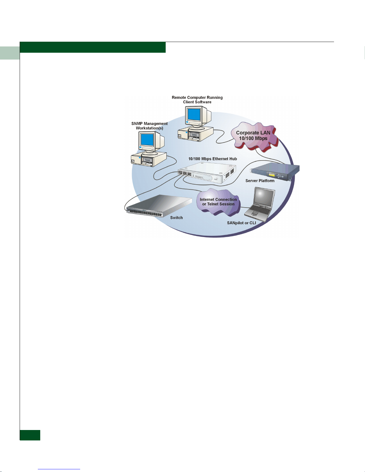
Figure 1-1 illustrates out-of-band product management. In the figure,
the managed product is a Sphereon fabric switch.
Figure 1-1 Out-of-Band Product Management
The following inband management access methods are provided as
options:
• Management through the product’s open-system management
server (OSMS) that communicates with an application client. The
application resides on an open-systems interconnection (OSI)
device attached to a switch port, and communicates using Fibre
Channel common transport (FC-CT) protocol. Product operation,
port connectivity, zoning, and fabric control are managed through
a device-attached console.
• Management through the product’s Fibre Connection (FICON)
management server (FMS) that communicates with the IBM
System Automation for OS/390 (SA OS/390) operating system.
The operating system resides on an IBM System/390
900 Parallel Enterprise Server attached to a director or switch
port, and communicates through a FICON channel. Control of
connectivity and statistical product monitoring are provided
through a host-attached console.
or zSeries
1-4
McDATA® Sphereon 3032 and 3232 Fabric Switches Installation and Service Manual
Page 31

General Information
1
Error-Detection,
Reporting, and
Serviceability
Features
The switch provides the following error-detection, reporting, and
serviceability features:
• Light-emitting diodes (LEDs) on switch FRUs and adjacent to
Fibre Channel ports that provide visual indicators of hardware
status or malfunctions.
• System and threshold alerts, event logs, audit logs, link incident
logs, threshold alert logs, and hardware logs that display switch,
Ethernet link, and Fibre Channel link status at the management
server, customer-supplied server (running the EFCM Lite
application), or a remote workstation.
• Diagnostic software that performs power-on self-tests (POSTs)
and port diagnostics (internal loopback, external loopback, and
Fibre Channel (FC) wrap tests). The FC wrap test applies only
when the switch is configured to operate in FICON management
mode.
• Automatic notification of significant system events (to support
personnel or administrators) through e-mail messages or the
call-home feature.
• An external modem for use by support personnel to dial-in to the
management server for event notification and to perform remote
diagnostics.
• An RS-232 maintenance port at the rear of the switch (port access
is password protected) that enables installation or service
personnel to change the switch’s internet protocol (IP) address,
subnet mask, and gateway address; or to run diagnostics and
isolate system problems through a local or remote terminal.
• Redundant FRUs; (small form factor pluggable (SFP)) optical
transceivers, power supplies, and cooling fans that are removed
or replaced without disrupting switch or Fibre Channel link
operation.
• A modular design that enables quick removal and replacement of
FRUs without tools or equipment.
• Concurrent port maintenance. SFPs and Fiber-optic cables are
removed and attached to ports without interrupting other ports
or director operation.
Switch Description
1-5
Page 32

General Information
1
• Beaconing to assist service personnel in locating a specific port or
switch. When port beaconing is enabled, the amber LED
associated with the port flashes. When unit beaconing is enabled,
the system error indicator on the front panel flashes. Beaconing
does not affect port or switch operation.
• Data collection through the Element Manager application to help
isolate system problems. The data includes a memory dump file
and audit, hardware, and engineering logs.
• Status monitoring of redundant FRUs and alternate Fibre
Channel data paths to ensure continued director availability in
case of failover. The SANavigator or EFCM 8 application queries
the status of each backup FRU daily. A backup FRU failure is
indicated by an illuminated amber LED.
• Simple network management protocol (SNMP) management
using the Fibre Alliance MIB that runs on the management server.
Up to 12 authorized management workstations can be configured
through the SAN Management application to receive unsolicited
SNMP trap messages. The trap messages indicate operational
state changes and failure conditions.
• SNMP management using the Fibre Channel Fabric Element MIB,
transmission control protocol/internet protocol (TCP/IP) MIB-II
definition (RFC 1213), or a product-specific MIB that runs on each
switch. Up to 12 authorized management workstations can be
configured through the Element Manager application to receive
unsolicited SNMP trap messages. The trap messages indicate
switch operational state changes and failure conditions.
• SNMP management using the Fibre Alliance MIB that runs on the
management server. Up to 12 authorized management
workstations can be configured through the SAN Management
application to receive unsolicited SNMP trap messages. The trap
messages indicate operational state changes and failure
conditions.
NOTE: For more information about SNMP support provided by McDATA
products, refer to the McDATA OPENconnectors SNMP Support Manual
(620-000131).
1-6
McDATA® Sphereon 3032 and 3232 Fabric Switches Installation and Service Manual
Page 33

General Information
1
Zoning Feature
The switch supports a name server zoning feature that partitions
attached devices into restricted-access groups called zones. Devices
in the same zone can recognize and communicate with each other
through switched port-to-port connections. Devices in separate zones
cannot communicate with each other.
Zoning is configured by authorizing or restricting access to name
server information associated with device N_Ports that attach to
switch fabric ports (F_Ports). A zone member is specified by the port
number to which a device is attached, or by the eight-byte (16-digit)
worldwide name (WWN) assigned to the host bus adapter (HBA) or
Fibre Channel interface installed in a device. A device can belong to
multiple zones.
CAUTION
If zoning is implemented by port number, a change to the switch
fiber-optic cable configuration disrupts zone operation and may
incorrectly include or exclude a device from a zone.
CAUTION
If zoning is implemented by WWN, removal and replacement of a
device HBA or Fibre Channel interface (thereby changing the
device WWN) disrupts zone operation and may incorrectly include
or exclude a device from a zone.
CAUTION
In Open Fabric mode, only zoning by WWN is supported. Zoning
by port numbers is not.
Zones are grouped into zone sets. A zone set is a group of zones that
is enabled (activated) or disabled across all switches in a multiswitch
fabric. Only one zone set can be enabled at one time.
Switch Description
1-7
Page 34

General Information
1
Multiswitch Fabrics
A Fibre Channel topology that consists of one or more interconnected
switches or switch elements is called a fabric. Operational software
provides the ability to interconnect switches (through expansion port
(E_Port) connections) to form a multiswitch fabric. The data
transmission path through the fabric is typically determined by fabric
elements and is user-transparent. Subject to zoning restrictions,
devices attached to any interconnected switch can communicate with
each other through the fabric.
Because a multiswitch fabric is typically complex, maintenance
personnel should be aware that several factors can degrade fabric
performance or cause connectivity failures. These factors include:
• Domain ID assignment - Each switch in a fabric is identified by a
unique domain ID that ranges from 1 through 31. A domain ID of
0 is invalid. If two operational fabrics join, they determine if any
domain ID conflicts exist between the fabrics. If one or more
conflicts exist, the E_Ports that form the interswitch link (ISL)
segment to prevent the fabrics from joining.
• Zoning - In a multiswitch fabric, zoning is configured on a
fabric-wide basis, and any change to the zoning configuration is
applied to all switches in the fabric. To ensure zoning is consistent
across a fabric, the following rules are enforced when two fabrics
(zoned or unzoned) join:
1-8
— Fabric A unzoned and Fabric B unzoned - The fabrics join
successfully, and the resulting fabric remains unzoned.
— Fabric A zoned and Fabric B unzoned - The fabrics join
successfully, and fabric B automatically inherits the zoning
configuration from fabric A.
— Fabric A unzoned and Fabric B zoned - The fabrics join
successfully, and fabric A automatically inherits the zoning
configuration from fabric B.
— Fabric A zoned and Fabric B zoned - The fabrics join
successfully only if the zone configurations can be merged. If
the fabrics cannot join, the connecting ports segment and the
fabrics remain independent.
Zone configurations for two fabrics are compatible (the zones can
join) if the active zone set name is identical for each fabric, and if
zones with the same name have identical elements.
McDATA® Sphereon 3032 and 3232 Fabric Switches Installation and Service Manual
Page 35

General Information
• Port segmentation - When an ISL activates, the switches
exchange operating parameters to determine if they are
compatible and can join to form a single fabric. If incompatible,
the connecting E_Port at each switch segments to prevent the
creation of a single fabric. A segmented link transmits only Class
F traffic; the link does not transmit Class 2 or Class 3 traffic. The
following conditions cause ports to segment:
— Incompatible operating parameters - Either the resource
allocation time-out value (R_A_TOV) or error-detect time-out
value (E_D_TOV) is inconsistent between switches. To prevent
port segmentation, the same E_D_TOV and R_A_TOV must
be specified for each switch.
— Duplicate domain IDs - One or more domain ID conflicts are
detected.
— Incompatible zoning configurations - zoning configurations
for the switches are not compatible.
— Build fabric protocol error - A protocol error is detected
during the process of forming the fabric.
1
— No principal switch - No switch in the fabric is capable of
becoming the principal switch.
NOTE: At least one director or switch in a multiswitch fabric must be set to
either principal or default, making it capable of becoming principal switch. If
all directors and switches are set to never principal, all ISLs will segment
(Reason code 05).
— Unresponsive switch - Each switch in a fabric periodically
verifies operation of all attached switches. An ISL segments if
the attached switch does not respond to a verification request.
— ELP retransmission failure timeout - A switch that exhibits a
hardware failure or connectivity problem cannot transmit or
receive Class F frames. The director did not receive a response
to multiple exchange link protocol (ELP) frames, did not
receive a fabric login (FLOGI) frame, and cannot join an
operational fabric.
Switch Description
1-9
Page 36

General Information
1
Switch Specifications
This section lists the physical characteristics, storage and shipping
environment, operating environment, and service clearances for the
Sphereon 3032 and Sphereon 3232Switches.
Physical
Characteristics
Dimensions:
Height: 6.5 centimeters (2.6inches)
Width: 44.5 centimeters (17.5 inches)
Depth: 64.1 centimeters (25.2 inches)
Weight: 16.8 kilograms (37 pounds)
Power Requirements:
Input voltage: 100 to 240 VAC
Input Frequency: 47 to 63 Hz
Input Current:
3032 - 1.0 amps at 208 VAC
3232 - 1.3 amp at 208 VAC
Plan for single phase or phase-to-phase connections and
5-ampere dedicated service
Airflow Clearance in Rack:
Sides: None
1-10
McDATA® Sphereon 3032 and 3232 Fabric Switches Installation and Service Manual
Top and Bottom: None
Front and Rear: 7.6 centimeters (3.0 inches)
Heat Dissipation:
3032:
682 BTU/Hr (200 watts)
3232:
836 BTU/Hr (245 watts)
Shock and Vibration Tolerance:
60 Gs for 10 milliseconds without nonrecoverable errors
Page 37

Acoustical Noise:
70 dB “A” scale
Inclination:
°
10
maximum
General Information
1
Storage and Shipping
Environment
Operating
Environment
Protective packaging must be provided to protect the switch under
all shipping methods (domestic and international).
Shipping temperature:
°
-40
C to 60° C (-40° F to 140° F )
Storage temperature:
°
1
C to 60° C (34° F to 140° F)
Shipping relative humidity:
5% to 100%
Storage relative humidity:
5% to 80%
Maximum wet-bulb temperature:
°
29
C (84° F )
Altitude:
40,000 feet (12,192 meters)
Temperature:
°
4
C to 40° C (40° F to 104° F)
Relative humidity:
Maximum wet-bulb temperature:
Altitude:
8% to 80%
°
27
C (81° F)
3,048 meters (10,000 feet)
Switch Specifications
1-11
Page 38

General Information
1
Management
Server
The management server is a one rack unit (1U) high, LAN-accessed,
rack- mount unit that provides a central point of control for up to 48
connected switches or other McDATA managed products. The server
desktop is accessed through a LAN-attached PC and standard web
browser. Figure 1-2 illustrates the management server with attached
liquid crystal display (LCD) panel.
Figure 1-2 Management Server
Management Server
Specifications
The server is rack mounted in the McDATA-supplied FC-512
Fabricenter equipment cabinet. The SANpilot interface or
management server is required to install, configure, and manage the
switch.
The management server provides two auto-detecting 10/100 Mbps
Ethernet LAN connectors (RJ-45 adapters). The first adapter (LAN 1)
attaches (optionally) to a public customer intranet to allow access
from remote user workstations. The second adapter (LAN 2) attaches
to a private LAN segment containing switches or managed McDATA
products.
The following list summarizes hardware specifications for the EFC
Server rack-mount platform. Current platforms may ship with more
enhanced hardware, such as a faster processor, additional randomaccess memory (RAM), or a higher-capacity hard drive.
®
• 1U rack-mount server running the Intel
Pentium® 4 processor
with an 1,800 megahertz (MHz) or greater clock speed, Microsoft
®
Windows
2000 Professional operating system, and power cord.
1-12
McDATA® Sphereon 3032 and 3232 Fabric Switches Installation and Service Manual
Page 39

General Information
• TightVNC™ Viewer Version 1.2.7 client-server software control
package that provides remote network access (through a standard
web browser) to the EFC Server desktop.
• 1,024 megabyte (MB) or greater RAM.
• 40 gigabyte (GB) or greater internal hard drive.
• 1.44 MB 3.5-inch slim-type disk drive and slim-type compact
disk-rewritable (CD-RW) drive.
• 56K internal modem.
• Two 10/100 Mbps Ethernet adapters with RJ-45 connectors.
1
Ethernet Hub
(Optional)
.
The management server and managed switches connect through a
10/100 Base-T Ethernet hub. Figure 1-3 illustrates the 24-port hub.
1
4
5
13
8
9
16
17
12
20
21
M
ID
MDIX
24
1
2
3
13
14
15
Green-100M, Yellow - 10M, Flash - Activity
Figure 1-3 24-Port Ethernet Hub
Hubs can be interconnected to provide additional connections as
more switches (or other McDATA managed products) are installed
on a network. Multiple hubs are daisy-chained by attaching RJ-45
Ethernet patch cables and configuring each hub through a mediumdependent interface (MDI) switch.
PortStatus
4
5
6
7
16
8
17
9
18
Collision
10
19
11
20
12
21
22
23
24
Baseline
100M
10M
10/100
Power
Hub
3C16411
SuperStack
®
3
3
com
®
SANpilot Interface
The SANpilot interface provides a GUI accessed through the Internet
(locally or remotely) to manage, monitor, and isolate problems for the
Switch. When the interface opens, the default display is the View
panel.
Task selection tabs appear at the top of the panel, a graphical
representation of the switch hardware (front and rear) appears at the
right side of the panel, and menu selections (Vie w, Configure, Monitor,
Switch Specifications
1-13
Page 40

General Information
1
Operations, and Help) appear at the left side of the panel. The task
selection tabs allow personnel to perform switch-specific tasks, and
are a function of the menu selected as follows:
• View - At the Vi ew panel, the Switch (default), Port Properties, FRU
Properties, Unit Properties, Operating Parameters, and Fabric task
selection tabs appear.
• Configure - At the Configure panel, the Ports (default), Switch,
Management, Zoning, Security, and Performance task selection tabs
appear.
• Monitor - At the Monitor panel, the Port List (default), Port Stats,
Log, and Node List task selection tabs appear.
• Operations - At the Operations panel, the Switch (default), Port,
Maintenance, and Feature Installation task selection tabs appear.
• Help - The Help selection opens online user documentation that
supports the SANpilot interface.
Maintenance Approach
Whenever possible, the maintenance approach instructs service
personnel to perform fault isolation and repair procedures without
degrading or interrupting operation of the switch, attached devices,
or associated applications. Switch fault isolation begins when one or
more of the following occur:
• System event information displays at the attached management
server, a remote workstation communicating with the
management server, or the SANpilot interface.
• LEDs on the switch front panel or FRUs illuminate to indicate a
hardware malfunction.
• An unsolicited SNMP trap message is received at a management
workstation, indicating an operational state change or failure.
• Notification of a significant system event is received at a
designated support center through an e-mail message or the
call-home feature.
System events can be related to a:
• Switch or management server failure (hardware or software).
1-14
McDATA® Sphereon 3032 and 3232 Fabric Switches Installation and Service Manual
Page 41

General Information
• Ethernet LAN communication failure between the switch and
management server
• Link failure between a port and attached device.
• ISL failure or segmentation of an E_port.
Fault isolation and service procedures vary depending on the system
event information provided. Fault isolation and related service
information is provided through maintenance analysis procedures
(MAPs) documented in Chapter 3. MAPs consist of step-by-step
procedures that prompt service personnel for information or describe
a specific action to be performed. MAPs provide information to
interpret system event information, isolate a switch failure to a single
FRU, remove and replace the failed FRU, and verify switch operation.
The fault isolation process normally begins with Map 000.
Ensure the correct switch is selected for service (if the management
server manages multiple switches or other McDATA products) by
enabling unit beaconing at the failed switch. The amber system error
(ERR) LED on the switch front panel blinks when beaconing is
enabled. Instructions to enable beaconing are incorporated into MAP
steps.
1
Remote Workstation Configurations
Using a standard web browser, the SAN Management application
and Element Manager applications can be downloaded and installed
on remote user workstations that are LAN-attached to the
management server.
Operators at these workstations can manage and monitor switches
controlled by the management server. A maximum of five concurrent
users (including a local user) can log in to the SAN Management
application.
Each remote workstation must have access to the LAN segment on
which the management server is installed. Switch administrative
functions are accessed through the LAN and management server. The
LAN interface can be:
• Part of the dedicated 10/100 Mbps LAN segment that provides
access to managed switches. This switch-to-management server
LAN connection is part of the equipment installation and is
required. Connection of remote workstations can be through the
McDATA Ethernet hub or through the customer intranet. A
Remote Workstation Configurations
1-15
Page 42

General Information
1
network configuration using the customer intranet and one
Ethernet connection through the management server is shown in
Figure 1-4.
Figure 1-4 Typical Network Configuration (One Ethernet Connection)
• Part of a second management server interface that connects to a
customer intranet and allows operation of the Element Manager
application from remote user PCs or workstations. Connection to
this LAN segment is optional and depends on customer
requirements. A network configuration using both Ethernet
connections is shown in Figure 1-5.
1-16
McDATA® Sphereon 3032 and 3232 Fabric Switches Installation and Service Manual
Page 43

Figure 1-5 Typical Network Configuration (Two Ethernet Connections)
General Information
1
Both Ethernet adapters in the management server provide
auto-detecting 10/100 Mbps connections. The dedicated LAN
segment that connects the management server to managed switches
and the optional customer intranet operate at either ten or 100 Mbps.
If only one management server connection is used and this
connection is provided through the customer intranet, functions
provided by the management server are available to all users. The
purpose for dual LAN connections is to provide a dedicated LAN
segment that isolates the management server and managed switches
from unauthorized users.
CAUTION
Prior to servicing a switch or management server, determine the
Ethernet LAN configuration. Installation of switches and the
management server on a public customer intranet can complicate
problem determination and fault isolation.
Remote Workstation Configurations
1-17
Page 44

General Information
1
Minimum Remote
Console Hardware
Specifications
Client EFC Manager and Product Manager applications download
and install to remote workstations (from the EFC Server) using a
standard web browser. The applications operate on platforms that
meet the following minimum system requirements:
• Desktop or notebook PC with color monitor, keyboard, and
mouse, using an Intel Pentium processor with a 400 MHz or
greater clock speed, and using the Microsoft Windows 95,
Windows 98, Windows
2000, Windows XP, Windows NT 4.0, or
Linux 2.2 operating system.
• Unix workstation with color monitor, keyboard, and mouse,
using a:
®
— Hewlett-Packard
greater clock speed, using the HP-UX
HA PA-RISC® processor with a 400 MHz or
®
11 or higher operating
system.
®
—Sun
Microsystems UltraSPARC™ II processor with a 400
MHz or greater clock speed, using the SunOS™ Version 5.5.1
or higher operating system, or Solaris™ Version 2.5.1 or higher
operating system.
®
—IBM PowerPC
microprocessor with a 400 MHz or greater
clock speed, or POWER3™ microprocessor with a 400 MHz or
greater clock speed, using the AIX Version 4.3.3 or higher
operating system.
Field-Replaceable Units
1-18
McDATA® Sphereon 3032 and 3232 Fabric Switches Installation and Service Manual
• At least 15 MB available on the internal hard drive.
• 128 MB or greater RAM.
• Video card supporting 256 colors at 800 x 600 pixel resolution.
• Ethernet network adapter.
• Java-enabled Internet browser, such as Microsoft Internet
Explorer (Version 4.0 or later) or Netscape Navigator (Version 4.6
or later).
The switch provides a modular design that enables quick removal
and replacement of FRUs (small form factor pluggable SFP)) optical
transceivers, power supplies, and fans). Figure 1-6 illustrates the
front of the switch. SFPs installed in the ports are the only FRUs
accessed from the front. The switch front panel also includes:
Page 45

General Information
• An initial machine load (IML) button.
• An Ethernet LAN connector.
• Green power (PWR) and amber system error (ERR) LEDs.
1
Initial Microcode
Load (IML)
Button
Ethernet
Connector
IML
24
262830
SFF Fibre Optic
Connectors (32)
TM
Port
LEDs (64)
Figure 1-6 Sphereon 3032/3232 Switch (Front View)
Figure 1-7 illustrates the rear of the switch. The rear panel includes
two power supplies, six cooling fans, and an RS-232 maintenance
port.
1
35791113151719212325272931
0246810121416182022
Power (PWR)
LED
PWR
ERR
Error (ERR)
LED
Fan
Module
Figure 1-7 Sphereon 3032/3232 Switch (Rear View)
SFP Transceivers
A singlemode or multimode fiber-optic cable attaches to a port
through a pluggable small form factor (SFP) transceiver. The SFP
provides a duplex LC
switch port for easy replacement. The following fiber-optic
transceiver types are available:
AC IN 1
Power
Receptacle
Power
Switch
Fan
Modules
AC IN 0
Power
Power
Switch
Receptacle
®
interface, and can be detached from the
Field-Replaceable Units
1-19
Page 46

General Information
1
NOTE: All of the following transceiver types can be used in either the 1 Gbps
or 2 Gbps switches, however a 1 Gbps transceiver used in a 2 Gbps switch
will limit that port to a 1 Gbps data rate.
• Shortwave laser (1.0625 Gbps) - Shortwave laser transceivers
provide connections for transferring 1.0625 Gbps data over short
distances as follows:
— Up to 500 meters through 50-micron multimode fiber.
— Up to 300 meters through 62.5-micron multimode fiber.
• Shortwave laser (2.125 Gbps) - Shortwave laser transceivers
provide connections for transferring 2.125 Gbps data over short
distances as follows:
— Up to 300 meters through 50-micron multimode fiber.
— Up to 150 meters through 62.5-micron multimode fiber.
• Longwave laser (1.0625 Gbps) - Longwave laser transceivers
provide connections for transferring 1.0625 Gbps data up to 10
kilometers through 9-micron singlemode fiber.
Cooling Fans
Power Supplies
• Longwave laser (2.125 Gbps) - Longwave laser transceivers
provide connections for transferring 2.125 Gbps data up to 10
kilometers through 9-micron singlemode fiber.
• Extended longwave laser (2.125 Gbps) - Two types of extended
longwave laser transceivers provide connections for transferring
2.125 Gbps data up to 20 kilometers or 35 kilometers through
9-micron singlemode fiber.
Four fans (each a separate FRU) provide cooling for the switch power
supplies and the control processor (CTP) card, as well as redundancy
for continued operation if a single fan fails.
Anyfan FRU can be replaced while the switch is operating.
Redundant, load-sharing power supplies step down and rectify
facility input power to provide 3.3 volt direct current (VDC), 5 VDC,
and 12 VDC to the CTP card. The power supplies also provide input
filtering, overvoltage protection, and overcurrent protection. Either
power supply can be replaced while the switch is operational.
1-20
McDATA® Sphereon 3032 and 3232 Fabric Switches Installation and Service Manual
Page 47

Each power supply has a separate CTP card connection to allow for
independent AC power sources. The power supplies are input-rated
at 100 to 230 volts alternating current (VAC).
Connectors and Indicators
Connectors and indicators include the:
• Initial machine load (IML) button.
• Ethernet LAN connector.
• Green power (PWR) and amber system error (ERR) LEDs.
• Green and amber status LEDs associated with FRUs.
• RS-232 maintenance port.
General Information
1
Initial Machine Load
Button
Ethernet LAN
Connector
When the IML button (Figure 1-6 on page 1-19) is pressed and held
for three seconds, the switch performs an IML that takes
approximately 30 seconds and resets the:
• Microprocessor and functional logic for the CTP card and loads
firmware from FLASH memory.
• Ethernet LAN interface, causing the connection to the
management server to drop momentarily until the connection
automatically recovers.
• Ports, causing all Fibre Channel connections to drop momentarily
until the connections automatically recover.
An IML should only be performed if a CTP card failure is indicated.
Do not IML the switch unless directed to do so by a procedural step
in this manual,or the next level of support. As a precaution, the IML
button is flush mounted to protect against accidental activation.
The front panel provides a 10/100 megabit per second (Mbps) RJ-45
twisted-pair connector (Figure 1-6 on page 1-19) that attaches to an
Ethernet LAN to provide communication with the management
server or an SNMP management workstation. Two green LEDs are
associated with the LAN connector. When illuminated, the left LED
indicates LAN operation at 10 Mbps, and the right LED indicates
LAN operation at 100 Mbps.
Connectors and Indicators
1-21
Page 48

General Information
1
Power and System
Error LEDs
FRU Status LEDs
The PWR LED (Figure 1-6 on page 1-19) illuminates when the switch
is connected to facility AC power and powered on. If the LED
extinguishes, a facility power source, power cord, or power
distribution failure is indicated.
The ERR LED (Figure 1-6 on page 1-19) illuminates when the switch
detects an event requiring immediate operator attention, such as a
FRU failure. The LED remains illuminated as long as an event is
active. The LED extinguishes when the Clear System Error Light
function is selected from the Element Manager application. The LED
blinks if unit beaconing is enabled. An illuminated ERR LED
(indicating a failure) takes precedence over unit beaconing.
Amber and green LEDs associated with switch FRUs provide status
information as follows:
• Port SFP - Amber and green LEDs to the left of the port
(Figure 1-6 on page 1-19) illuminate, extinguish, or blink to
indicate various port states (operational with active Fibre
Channel traffic, operational but not communicating, beaconing,
blocked, failed, inactive, or running diagnostics).
• Fan - An amber LED at the lower left corner of each fan
(Figure 1-7 on page 1-19) illuminates if the fan fails or rotates too
slowly.
Maintenance Port
1-22
McDATA® Sphereon 3032 and 3232 Fabric Switches Installation and Service Manual
• Power Supply - A green LED at the upper left corner of each
power supply (Figure 1-7 on page 1-19) illuminates if the power
supply is operational and receiving AC power.
The rear panel provides a 9-pin RS-232 maintenance port (Figure 1-7
on page 1-19) that provides a connection for a local terminal or dial-in
connection for a remote terminal. Although the port is typically used
by authorized maintenance personnel, operations personnel can use
the port to configure switch network addresses.
Page 49

Software Diagnostic Features
The switch provides the following diagnostic software features that
aid in fault isolation and repair of problems:
• FRUs provide on-board diagnostic and monitoring circuits that
continuously report FRU status to the SAN Management and
element Manager applications. These applications provide
system alerts and logs that display failure and diagnostic
information at the management server or a remote workstation
communicating with the management server.
• The EFC Management Services (EMS) application that runs as a
Windows 2000 service and provides an additional user interface
to display operational status.
• The SANpilot interface that provides Internet access to isolate
problems for a single switch.
• Unsolicited SNMP trap messages that indicate operational state
changes or failures can be transmitted to up to 12 authorized
management workstations.
General Information
1
SAN Management
Application
• E-mail messages or call-home reports provide automatic
notification of significant system events to designated support
personnel or administrators.
Access Element Managers for director and switch products through
SAN management application. Right-click the product icon on the
application Physical Map (topology) and select Element Manager from
the pop-up menu.
NOTE: In the following figure, the Model XXXX under the product icon will
be replaced with an actual switch or director model number in your SAN
management application Physical Map (topology).
Software Diagnostic Features
1-23
Page 50

General Information
1
Besides access to director and switch Element Managers, you may
configure some features through both your SAN management
application and through the Element Manager. You must also enable
Element Manager feature permissions for Administrative, Operator,
and Maintenance user levels through your SAN management
application. When this refers to your Management Application for
specific tasks, you should see the application online help or User
Manual for detailed instructions.
Element Manager Description
The Element Manager for your switch is a Java-based graphical user
interface (GUI) that provides in-depth management, configuration,
and monitoring functions for individual switches and their
field-replaceable units (FRUs). Although each Element Manager is
accessed from your SAN Management application, it is a separate
application.
The Element Manager provides graphical views of switch hardware
components and displays of component status. By positioning the
cursor on icons, graphics, panels, and other visual elements in these
1-24
McDATA® Sphereon 3032 and 3232 Fabric Switches Installation and Service Manual
Page 51

General Information
views and clicking the left or right mouse button, you can quickly
manage and monitor the switch on your network.
Access the switch Element Manager, by right-clicking a switch
product icon in the SAN management application Physical Map
(topology) and selecting the Element Manager from the menu that
displays.
The server software for the SAN management and Element Manager
application may be installed on a server platform (computer system)
shipped by your supplier or it may be installed on a server platform
provided by the customer.
You can install the SAN management and Element Manager client
applications on remote computer systems For instructions, refer to
the section in your SAN management application Software User
Manual that pertains to the operating system of your workstation.
Using the Element Manager, you can:
• Back up and restore configuration data.
1
• Change management style between FICON and open systems.
• Clear the system error indicator.
• Configure extended distance buffering for ports.
• Configure Fibre Channel operating parameters for the switch,
such as BB_Credit, R_A_TOV, E_D_TOV, preferred domain ID,
switch priority, Domain RSCNs, preferred and insistent domain
ID, and rerouting delay.
• Configure individual ports with a port name describing the node
attached to the port.
• Configure keys for new features.
• Configure interoperability mode for open switch fabrics.
• Configure LIN alerts.
• Configure Port Binding.
• Configure Nickname to display instead of WWN for the switch
and attached devices.
• Configure port address configurations. (FICON management
style only).
• Configure SNMP trap recipients and community names.
Element Manager Description
1-25
Page 52

General Information
1
• Configure the FICON and Open Systems Management Server
features if optional FICON and Open Systems Management
Server is installed.
• Configure Switch Binding if optional SANtegrity Binding feature
is installed.
• Configure Open Trunking if optional OpenTrunking feature is
installed.
• Configure the management style between open systems and
FICON management.
• Configure the switch name, location, description, and contact
person.
• Control individual Fibre Channel ports by blocking/unblocking
operation, enabling LIN alerts and port binding, setting data
speeds, and running internal and external loopback diagnostics.
• Display field replaceable unit (FRU) properties such as the FRU
name, physical position in the switch (chassis slot number), active
failed state, part number, and serial number.
• Display information for individual Fibre Channel ports, such as
the port name, port number, Fibre Channel address, operational
state, type of port, and login data.
• Display information on nodes attached to ports.
• Display port performance and statistics.
• Display vital product data for the switch, such as the system
name, description, contact person, location, status, model
number, firmware and EC level, and manufacturer.
• Enable beaconing for ports and the switch unit.
• Maintain a port address library (FICON management style only).
• Monitor the operational status of the switch and each of its
hardware field-replaceable units.
• Perform an initial program load (IPL).
• Perform maintenance tasks for the switch including maintaining
firmware levels, administering the Call Home Notification
feature, accessing the switch logs, and collecting data to support
failure analysis.
1-26
McDATA® Sphereon 3032 and 3232 Fabric Switches Installation and Service Manual
Page 53

Table 1-1 Status Symbols
Alert Symbol Meaning
Green circle Status Bar: All managed products are fully operational and no failures are indicated.
General Information
1
NOTE: The Call Home Notification feature may be optional, depending
on your purchased software package.
• Reset port operation.
•Run port diagnostics.
• Set the date and time on the switch.
• Swap addresses between ports (FICON management style only).
• Use standard keyboard navigation in dialog boxes. For example,
use the Ta b, arrow, and backspace keys to move through dialog
box fields and the Enter key to perform default button functions.
Next to Icon: The switch is fully operational and no failures are indicated.
Yellow triangle Status Bar: At least one managed product is operating in degraded mode.
Next to Icon: A redundant component failed or the switch is operating in degraded
mode. Service is required.
Red diamond (with
yellow background)
Grey square Status Bar: The status of at least one managed product is unknown.
Status Bar: At least one managed product is not operational.
Next to Icon: A critical failure occurred and the switch is not operational. Immediate
service is required.
Next to Icon: The switch status is unknown because of a network connection failure
between the switch and management server.
Using the Element Manager
This provides a general overview of the Element Manager and its
functions.
Using Dialog Boxes
Buttons such as OK, Activate and Close or Cancel initiate functions in a
dialog box. Click a button to perform its labeled function. There is a
difference between the Close and Cancel buttons. The Close button
closes the dialog box and saves the data you entered. The Cancel
Using the Element Manager
1-27
Page 54

General Information
1
button cancels the operation and closes the dialog box without saving
the information you entered.
Keyboard
Navigation
Hardware View
Window Layout and
Function
Keyboard navigation is an alternative to mouse navigation. The
Element Manager supports standard keyboard navigation.
NOTE: The SAN management application window is still available as a
separate window. You can drag the Element Manager window away from the
SAN management application window and view both windows on your PC
desktop or minimize one or both of them to icons if desired. You can have a
maximum of four Element Manager windows open concurrently.
The main Element Manager window is divided into four main areas.
The menu bar on the Element Manager window displays tabs for the
following menus:
•Product
• Configure
•Logs
• Maintenance
1-28
•Help
Click one of the tabs to display a list of menu options. Click an option
to open a dialog box that allows you to perform configuration and
maintenance tasks and view logs. If a menu option contains a check
box, click in the box to add a check mark and enable a function. Click
a check box containing a check mark to remove the check mark and
disable the function.
Product Menu
Select one of the following options from the Product menu.
Management Style
This provides a secondary menu with radio buttons for Open
Systems and FICON management styles. These options change some
Element Manager dialog boxes and options to allow management of
the switch in open systems or FICON environments.
McDATA® Sphereon 3032 and 3232 Fabric Switches Installation and Service Manual
Page 55

General Information
• Open Systems. Click this radio button for (non-FICON) Fibre
channel environments.
• FICON. Typically, select this radio button when attaching an
IBM S/390 Parallel Enterprise or zSeries server to the switch
and implementing inband director management through a
Fibre Connection (FICON) channel. If switch firmware level is
below 6.0 and the FICON Management Server feature is
enabled, the default management style will be FICON. The
management style cannot be changed to Open Systems with
the FICON Management Server feature enabled.
NOTE: If firmware versions below 6.0 are installed on the switch, you need
to take the switch offline before changing the management style.
Port
This provides a secondary port menu only when the Hardware
View, Port List View, or Performance View displays in the view
panel. To use this menu for a specific port, click a port in the
Hardware View, a port row in the Port List View, or a port bar graph
in the Performance View. The menu contains options which are
identical to those that display when you right-click the port, port
row, or port bar graph in those views.
1
FRU
Click a power supply module or cooling fan module in the
Hardware View only and select FRU from the Product menu to
display the FRU Properties menu option. This option displays the
FRU Properties dialog box for the FRU. The FRU Properties dialog
box can also be displayed when you double-click the FRU in the
Hardware View.
Clear System Error Light
Select this to turn off the amber system error LED, located below
the green power LED on the switch front bezel.
Enable Unit Beaconing
Click the check box to toggle unit beaconing on or off. When the
check box has a check mark, unit beaconing is on, and the amber
system error light on the switch front bezel blinks to help users
locate the actual unit in an equipment room. When you click the
check box to remove the check mark, unit beaconing is disabled
Using the Element Manager
1-29
Page 56

General Information
1
and the amber LED goes out. You can only enable beaconing if
there are no system errors (the system error light is off) or if the
FRU has failed.
Properties
Click to display the Switch Properties dialog box. This dialog box
contains the switch name, description, location, and contact
person configured through the Configure Identification dialog box.
Also included is other product information as detailed in Switch
Properties. You can also display this dialog box by double-clicking
an area on the illustration in the Hardware View, away from a
hardware component.
Close
Select this option to close the Element Manager window.
Configure Menu
Click on the Configure menu on the menu bar to display the following
options.
Identification
Select this option to display the Configure Identification dialog box.
Enter the following information in this dialog box:
— Name - Assign a product name. Note that you can set this
name as the nickname for the switch WWN, using the Set
Name as Nickname check box. The nickname then displays
instead of the WWN in Element Manager views. The
maximum number of nicknames allowed is 2,048.
— Description - Assign a unique product description.
— Location - Describe the product location.
— Contact - Assign a contact either by name, phone number, or
e-mail address.
NOTE: This information displays in the identification table at the top of
the Hardware View and in your SAN management application Physical
Map (topology), if the Physical Map (topology) is configured to display
names.
1-30
McDATA® Sphereon 3032 and 3232 Fabric Switches Installation and Service Manual
Page 57

General Information
Switch Operating Parameters
Select this option to display the Configure Switch Parameters dialog
box for setting Fibre Channel operating parameters. In this dialog
box, you can set the preferred domain identification (1 to 31) and
make it insistent. You can also enable rerouting delay, domain
register for state change notifications (RSCNs), and Zoning
RSCNs). The switch must be offline to configure preferred
domain ID.
Fabric Operating Parameters
Select this option to display the Configure Fabric Parameters dialog
box for setting fabric operating parameters. In this dialog box,
you can set buffer-to-buffer credit (BB_Credit) from 1 to 60
(default is 16) and the resource allocation time-out value
(R_A_TOV) and error detect time-out value (E_D_TOV) in
tenth-of-a-second increments. In addition, you can set the switch
priority level (Principal, Default, or Never Principal) and the
interoperability modes between McDATA Fabric 1.0, and Open
Fabric 1.0.
1
The switch must be offline to configure any fabric operating
parameter.
Switch Binding
This submenu provides two options: Change State and Edit
Membership List.
•Selecting Change State displays the Switch Binding State Change
dialog box where you can activate Switch Binding according to a
specific connection policy (Restrict E_Ports, Restrict F_Ports, or
Restrict All Ports).
• Edit Membership List allows you to create a list of switches and
devices that you want to allow exclusively to attach to switch
ports. Switch Binding is an optional feature that requires the
SANtegrity Binding feature key. The feature can be installed
through the Configure Feature Key dialog box.
Ports
Select this option to display the Configure Ports dialog box. This
dialog has different functions in FICON versus Open Systems
management style.
Using the Element Manager
1-31
Page 58

General Information
1
In FICON management style, use the dialog box to enable
extended distance buffering for 10 to 100 km, link incident (LIN)
alerts, and port binding for each port.
In Open Systems management style, for each port you can
provide a name, block or unblock operation, configure extended
distance buffering for 10 to 100 km, enable LIN alerts for each
port, define a type (G, F, and E), and enable port binding.
NOTE: Ports are automatically configured as G_Ports if no device is
connected, F_Ports if a device is connected, and E_Ports if a switch is
connected.
In both styles, you can enable the rerouting delay feature.
Addresses
FICON management style only. Select from two suboptions for
active and stored addresses.
Active Addresses: Displays the Configure-Addresses - “Active”
dialog box. Use this dialog box to configure a name, blocked or
unblocked state, and prohibited and allowed connection
attributes for a port.
Stored Addresses: Displays the Address Configuration Library. Use
this dialog box to activate, modify, delete, and modify existing
address configurations created through the Active Addresses
dialog box.
SNMP Agent
Select this option to display the Configure SNMP dialog box. Use
this dialog box to configure network addresses and community
names for up to six SNMP trap recipients. Also authorize write
permissions to enable SNMP management stations to modify
writable MIB variables. In addition, you can enable authorization
traps to be sent to management stations when unauthorized
stations request access to switch SNMP data.
Management Server
Select this option to display either the Configure Open Systems
Management Server or Configure FICON Management Server dialog
box, depending on which feature (if any) is enabled for the
switch. Use this to configure a FICON or open systems inband
management program to function with the switch. To use these
1-32
McDATA® Sphereon 3032 and 3232 Fabric Switches Installation and Service Manual
Page 59

General Information
procedures, you must have enabled either the FICON
Management Server or Open Systems Management Server
through the Configure Feature Key dialog box.
Features
Displays the Configure Feature Key dialog box. Use this dialog box
to enter a feature key to enable optional features that you have
purchased for the switch.
Date and Time
Select this option to display the Configure Date and Time dialog
box. Use this option to set the current date and time in the switch.
When the Periodic Date/Time Synchronization check box is checked,
the Date and Time fields are unavailable, and the Management
Server date and time periodically synchronizes the switch date
and time. If the Periodic Date/Time Synchronization check box is not
checked, you can set the date and time in the dialog box fields
manually.
1
Threshold Alert(s)
Select this option to configure threshold alerts for ports. A
threshold alert notifies users when the transmit (Tx) or receive
(Rx) throughput reaches specified values for specific switch ports
or port types (E_Ports or F_Ports). Using this option, you can
configure:
— A name for the alert.
— A threshold type for the alert (Rx, Tx, or both).
— Active or inactive state of the alert.
— Threshold criteria. This includes configuring the threshold as
the percent of port traffic capacity utilized (% utilization). You
must also configure the time interval during which the
throughput is measured and the maximum cumulative time
that the throughput percentage threshold can be exceeded
during this time interval before an alert is generated.
Open Trunking
Select this option to enable the optional OpenTrunking feature.
This feature monitors the average data rates of all traffic flows on
ISLs (from a receive port to a target domain) and periodically
adjusts routing tables to reroute data flows from congested links
to lightly loaded links and optimize bandwidth use. The feature
can be installed through the Configure Feature Key dialog box.
Using the Element Manager
1-33
Page 60

General Information
1
Export Configuration Report
Select this option to display the Export Configuration Report dialog
box, which enables you to specify a file name in which to save an
ASCII text file containing all current user-definable configuration
options in a printable format. Note that this file cannot be read
back into the Element Manager in order to set configuration
parameters.
Enable Web Server
Select this option to place a check mark in the check box to enable
the SANpilot interface on the switch. Select the option again to
remove the check mark and disable the SANpilot interface. When
disabled, users at remote computers running the client software
cannot access the SANpilot interface.
Enable Telnet
Select this option to place a check mark in the check box to enable
telnet access to the switch. Select the option again to remove the
check mark and disable telnet access. When disabled, users at
remote workstations cannot access the switch through telnet to
use the Command Line Interface (CLI) or perform other tasks.
Logs Menu
Click the Logs menu to display the following options.
Audit Log
This log provides a record of all configuration changes made on
the switch. Each entry displays the date and time of the change, a
description of the change, the source of the change (such as the
Management Server or SNMP management station), and an
identifier for the source, such as the IP address of the
Management Server or SNMP management station.
Event Log
Select this option to display the switch event log. This log
provides a record of significant events that have occurred on the
switch, such as hardware failures, degraded operation, and port
problems. Each entry includes the date and time of the event, a
reason code for the event, the severity level, a brief description,
and up to 32 bytes of supplementary event data. For more
information, refer to Appendix B.
1-34
McDATA® Sphereon 3032 and 3232 Fabric Switches Installation and Service Manual
Page 61

General Information
Hardware Log
This log displays information on FRUs inserted and removed
from the switch. Each log entry includes the name of the FRU
inserted or removed, the slot position relative to identical FRUs
installed, whether the FRU was inserted or removed, the FRU
part number and serial number, and the date and time the FRU
was inserted or removed.
Link Incident Log
The link incident (LIN) log displays the most recent incidents
with their date and time, port number, and description of the
incident. A link incident can be one of several conditions detected
on a fiber optic link.
Threshold Alert Log
This log provides notifications of threshold alerts. Besides the
date and time that the alert occurred, it also displays information
that was configured through the Configure Threshold Alert(s)
option under the Configure menu. This includes the alert name,
port for which the alert is configured, the type of alert (transmit
throughput, receive throughput, or both), threshold utilization of
traffic capacity, minutes the threshold was configured for, and the
configured time interval for the threshold.
1
Open Trunking Log
This log provides details on flow rerouting that occurs through
switch ports.
Maintenance Menu
Click the Maintenance menu to display the following options.
Port Diagnostics
This option displays the Port Diagnostics dialog box. Use this
dialog box to run internal and external loopback tests on ports.
Swap Ports
FICON management style only. Select this option to display the
Swap Ports dialog box. Use this dialog box to swap one port
address for another.
Data Collection
This option displays the Save Data Collection dialog box. Use this
dialog box to collect maintenance data into a file. This file is used
by support personnel to diagnose system problems.
Using the Element Manager
1-35
Page 62

General Information
1
IPL
Select this option to initiate an initial program load on the switch.
A dialog box displays to allow you to confirm the IPL. Note that
an IPL does not affect any configuration settings done through
the Element Manager. This operation does not disrupt port
operation.
Set Online State
Select this option to display the Set Online State dialog box. Use
this dialog box to change the online state of the switch to offline
or online.
Firmware Library
Select this option to display the Firmware Library dialog box. This
dialog box displays all firmware versions currently installed on
the Management Server that can be downloaded to switches. Use
this dialog box to add a new firmware version to the
Management Server hard disk, modify the description displayed
for an existing version, delete a version from the PC, or download
(send) a version for operation on a switch.
Enable E-Mail Notification
The Simple Mail Transfer Protocol (SMTP) server and e-mail
recipient addresses are configured in your SAN management
application (not in the switch Element Manager). E-mail
notification is also initially enabled in your SAN management
application for all switches managed by your SAN management
application. Note, however, that the E-Mail Notification option on
the Element Manager Maintenance menu must be enabled
(checked) for e-mail notification to occur for the specific switch.
The default setting for the Enable E-Mail Notification function is
enabled (checked). To disable the function, select Enable E-Mail
Notification from the Maintenance menu to clear the check box.
Enable Call Home Notification
NOTE: The default setting for the Enable Call Home Notification feature is
disabled (unchecked).
Select Enable Call Home Notification from the Maintenance menu to
enable the call home notification feature for the switch.
1-36
McDATA® Sphereon 3032 and 3232 Fabric Switches Installation and Service Manual
Page 63

General Information
The parameters of the call home notification feature are
configured through your SAN management application. For
more information, refer to your SAN management application
Software User Manual.
NOTE: The Call Home Notification feature may be optional, depending
on your purchased software package.
Backup & Restore Configuration
Select this option to save the product configuration stored on the
switch to the Management Server hard disk or to restore the
configuration data from the Management Server. Only a single
copy of the configuration is kept on the server.
This backup is primarily for single-CTP systems, where a backup
is needed to restore the configuration data to a replacement CTP
card. You cannot modify the location or the file name of the saved
configuration.
1
NOTE: You can only restore the configuration to a switch with the same
IP address.
CAUTION
The following operation resets all configuration including any
optional features that have been installed. You will need to re-enter
your feature key to enable all optional features after resetting the
configuration.
Reset Configuration
Select this option to reset all switch configuration data back to the
factory defaults. A confirmation dialog box displays with a
warning upon selecting the option.
Help Menu
Click the Help menu to display the following options.
Contents
Select this option to display the Help window. The Help window
contains Contents, Index, and Glossary buttons and hypertext-
linked items to help you quickly navigate through information.
Use the forward (>) and back (<) buttons to scroll forward and
Using the Element Manager
1-37
Page 64

General Information
1
backward through the displayed help frames. Exit the help
feature at any time by clicking the Close icon at the top of the Help
window.
About
Select this option to display the version number for the Element
Manager and copyright information.
Click one of the view tabs across the top of the Element Manager
window to display the following views in the View panel.
• Hardware
•Port List
•Node List
• Performance
•FRU List
Views, selected from the view tabs, display under the tabs in the view
panel.
Hardware View
The Hardware View is a view that displays in the view panel when you
open the switch Element Manager. Other views may display,
depending on what view you displayed last before closing the
application. To return to this view from another view, click the
Hardware View tab.
In the Hardware View, colored indicators reflect the status of actual
LEDs on the switch FRUs. The status bar displays a symbol to
represent the most degraded status currently reported by any of the
switch FRUs. For example, for a port failure, indicated by a blinking
red and yellow diamond on a port, a yellow triangle displays on the
status bar to indicate a degraded condition. However, if a blinking
red and yellow diamond displays over both power supplies, the
status bar displays a red and yellow diamond, indicating a failure
that requires immediate attention.
Switch Menu
Double-click the switch graphic away from a FRU to display the
Switch Properties dialog box. Right-click a hardware graphic away
from a FRU to display the following options:
• Switch Properties
1-38
McDATA® Sphereon 3032 and 3232 Fabric Switches Installation and Service Manual
Page 65

General Information
• Enable Unit Beaconing
• Clear System Error Light
•IPL Switch
• Set Switch Date and Time
• Set Switch Online State
Port Menu
Double-click a port to display the Port Properties dialog box.
Right-click a port to display the following options:
• Node Properties
•Port Technology
• Block Port
• Enable Beaconing
• Channel Wrap (FICON management style only)
1
• Swap Ports (FICON management style only)
•Diagnostics
• Clear Link Incident Alert(s)
• Reset Port
•Port Binding
• Clear Threshold Alert(s)
Note that these same options are available when you click a port on
the Hardware View and select the port secondary menu from the
Product menu on the menu bar.
NOTE: For Node Properties, if a node is not logged in a message box displays
indicating that node information is not available.
Port List View
Select the Port List View tab. A table listing the port number, port
name, port address (FICON management style only), the
block/unblock configuration, operating state, port type, and alert
condition displays in the view panel.
The Port List View displays information about all ports installed in the
switch. All data is dynamic and updates automatically. Double-click
Using the Element Manager
1-39
Page 66

General Information
1
any row in this view to display the Port Properties dialog box for the
port.
Right-click a port row to display the same menu options that display
when you right-click a port in the Hardware View or a port bar graph
in the Performance View. These include:
• Port Properties
• Node Properties
•Port Technology
•Block Port
• Enable Beaconing
•Diagnostics
• Channel Wrap (FICON management style only)
• Swap Ports (FICON management style only)
• Clear Link Incident Alert(s)
• Reset Port
•Port Binding
• Clear Threshold Alert(s)
Note that these options are also available when you click a port row
and select the Port secondary menu from the Product menu on the
menu bar.
Node List View
Select Node List from view tabs. This view displays a table with
information about all node attachments or N_Ports that have logged
into existing F_Ports on the switch. Only N_Ports display in the Node
List View after nodes have logged in to the fabric. The columns that
display in the table include: port number where the node is attached,
the port address, unit type, WWN of the attached node (device), and
BB_Credit used by the attached node.
Double-click a port row to highlight it and display the Node Properties
dialog box for that port.
Right-click a port row to display the following menu options:
• Node Properties. Displays the Node Properties dialog box.
1-40
McDATA® Sphereon 3032 and 3232 Fabric Switches Installation and Service Manual
• Port Properties. Displays the Port Properties dialog box.
Page 67

General Information
• Define Nickname. Displays the Define Nickname dialog box, where
you can define a nickname to display for the attached device
instead of the device's 8-byte WWN.
• Display options. Allows you to display attached devices listed
under the Port WWN column in the Node List View by the device
nickname configured through the Define Nickname menu option
or the device's WWN.
Note that these options are also available when you click a port row,
then select the Port secondary menu from the Product tab on the menu
bar.
Performance View
Select the Performance view tab. This view provides a graphical
display of performance for all 32 ports. The top portion of the
Performance View displays bar graphs that show the level of
transmit/receive activity for each port. This information updates
every five seconds. Each bar graph also shows the percentage link
utilization for the port. A red arrow marks the highest utilization
level reached since the Performance View was opened. If the system
detects activity on a port, it represents minimal activity with at least
one bar.
1
When an end device (node) is logged into a port, moving the cursor
over the port bar graph in the Performance View highlights the graph
and displays a message with the World Wide Name of the connected
node. If the connected node has more than one port, this is the World
Wide Name of the specific port on the node. When a port is
functioning as an expansion port (E_Port), the message is “E_Port.”
When a port is not logged into an end-device (not functioning as an
F_Port) or to another switch (not functioning as an E_Port), the
message is the port current online state.
Right-click a bar graph to display a menu of port-related actions. The
options available on this menu are the same as those that are
available when you right-click a port in the Hardware View or
right-click a row in the Port List View. These include:
• Port Properties
• Node Properties
•Port Technology
•Block Port
• Enable Beaconing
Using the Element Manager
1-41
Page 68

General Information
1
•Diagnostics
• Channel Wrap (FICON management style only)
• Swap Ports (FICON management style only)
• Clear Link Incident Alert(s)
• Reset Port
•Port Binding
• Clear Threshold Alert(s)
Note that these same options are also available when you click a port
graph, then select the Port secondary menu from the Product menu on
the menu bar.
The bottom portion of the Performance View displays cumulative
statistical information for the port selected in the bar graph. Values
are displayed for transmit and receive traffic, class 2 and 3 statistics,
operational statistics, and error categories. Click a category in the left
frame of the statistics area to display only statistics in that category or
click All to display values for all categories. Click Refresh to update
the data with current data from the port.
The Clear button clears all counters to zero. Selecting this button
displays a Clear Port Statistcs dialog box. Select the appropriate radio
button and click OK to clear all counters to zero on the selected port
only or counters on all ports on the switch.
NOTE: Clearing the counters clears the statistics for all users.
The status bar is located along the bottom of the Element Manager
window. This includes a symbol that displays at the left side of the
bar and messages that display in the panel to the right of the symbol.
The symbol indicates the current operating status of the switch and
the messages display to provide more description of menu options as
you move the cursor over the options under menu bar menus.
If a gray square displays in the status bar (no Ethernet connection), a
reason for the status displays in the Status table at the top of the
Hardware View.
1-42
McDATA® Sphereon 3032 and 3232 Fabric Switches Installation and Service Manual
Page 69

Table 1-2 Operating Bar and Switch Status
Symbol Status Bar Switch Status Table Text Meaning
Green Circle Fully Operational All components and installed ports are
General Information
1
operational; no failures.
Yellow
Triangle
Red
Diamond
with Yellow
Background
Gray Square Never Connected
Redundant Failure A redundant component has failed, such
Minor Failure A failure occurred which has decreased
NOT OPERATIONAL A critical failure prevents the switch from
Link Timeout
Protocol Mismatch
Duplicate Session
Unknown Network Address
Incorrect Product Type
as a power supply, and the backup
component has taken over operation.
the switch operational ability. Normal
switching operations are not affected.
• One or more ports failed, but at least
one port is still operational.
• A fan has failed or is not rotating
sufficiently.
performing fundamental switching
operations.
• All fans failed.
• All installed ports failed.
• Both power supplies failed.
Switch status is unknown. This occurs if
the Ethernet network connection between
the Management Server and the switch
cannot be established or if the CTP fails.
Messages display to the right of the status symbol as you move the
cursor over options under the menu bar menus. These messages
provide additional details about tasks that you can perform through
the menu option.
FRU List View
Select the FRU List view tab. A table with information about each of
the FRUs installed in the switch displays in the view panel. All data is
dynamic and updates automatically.
Using the Element Manager
1-43
Page 70

General Information
1
Closing the Element
Manager
SANpilot
Diagnostics
To close the Element Manager, do one of the following:
•Select Close from the Product menu on the menu bar.
• Click the X button at the top right corner of the Element Manager
window.
• Double-click the icon at the top left corner of the Element
Manager window, or right-click the icon and select Close from the
menu that displays.
If management server or customer-supplied server platform access is
not available, the SANpilot interface provides a GUI accessed
through the Internet (locally or remotely) to manage, monitor, and
isolate problems for a single switch. This interface is available with
switch firmware Version 1.2 (or later) installed, and does not replace
nor offer the full management capability of the EFC Manager and
Sphereon 3032/3232 Element Manager applications.
The SANpilot interface can be opened from a standard web browser
®
running Netscape Navigator
4.6 or higher or Microsoft Internet
Explorer 4.0 or higher. At the browser, enter the IP address of the
switch as the Internet uniform resource locator (URL). When
prompted at a login screen, enter a user name and password. When
the interface opens, the default display is the View panel. Service
personnel can perform the monitoring, configuration, maintenance
and diagnostic functions as follows:
1-44
• View panel - quickly inspect and determine the operational
status of the switch, and inspect switch properties and operating
parameters, FRU properties, and Fibre Channel port properties.
• Configure panel - configure or change:
—Switch ports.
— Switch identification, date and time, operating parameters,
and network addresses.
— SNMP trap message recipients.
— User passwords.
• Monitor panel - inspect and monitor:
— Fibre Channel ports and port performance statistics.
— The active zone set.
McDATA® Sphereon 3032 and 3232 Fabric Switches Installation and Service Manual
Page 71

General Information
— Event log entries, and clear the IML LED at the front panel.
— Information about attached devices (nodes).
• Operations panel - perform the following operations and
maintenance tasks:
— Enable port beaconing and perform port diagnostics (internal
and external loopback tests).
— Reset Fibre Channel ports.
— Set the switch online state.
— Upgrade switch firmware.
General tasks performed through the SANpilot interface are similar
in form and function to tasks performed through the EFC Manager
and Element Manager applications, and are therefore not
documented in this publication. For task information and
descriptions, open the online user documentation (Help selection)
that supports the interface.
1
SNMP Trap Message
Support
This publication provides instructions for switch installation and
fault isolation using the SANpilot interface. Refer to Chapter 2,
Installation Tasks for installation and configuration tasks. Refer to
Chapter 3, Diagnostics for fault isolation tasks.
Unsolicited SNMP trap messages that indicate switch operational
state changes or failure conditions can be customer-configured to be
transmitted to up to 12 management workstations. If installed on a
dedicated Ethernet LAN, the workstations communicate directly
with each switch. If installed on a customer intranet, the workstations
communicate with switches through the management server.
SNMP data and trap messages are defined in the Fibre Channel
FE-MIB definition, a subset of the TCP/IP MIB-II definition (RFC
1213), and a custom, switch-specific MIB. Customers can install these
MIBs (in standard ASN.1 format) on any SNMP management
workstation.
Although SNMP trap messages are typically transmitted to customer
personnel only, the messages may be provided to service personnel as
initial notification of a switch problem or as information included in
the fault isolation process. Generic SNMP traps include:
• coldStart - reports that the SNMP agent is reinitializing due to a
switch reset.
Using the Element Manager
1-45
Page 72

General Information
1
• warmStart - reports that the SNMP agent is reinitializing due to a
switch IPL.
• authorizationFailure - reports access by an unauthorized SNMP
manager. This trap is configurable, and is disabled by default.
Switch-specific SNMP traps specified in the custom MIB include
Fibre Channel port operational state changes and FRU operational
state changes.
If authorized through the Configure SNMP dialog box in the Element
Manager application, users at SNMP management workstations can
modify MIB variables. Switch modifications performed through
SNMP management work stations are recorded in the associated
Sphereon 3032/3232 Audit Log and are available through the Element
Manager application.
For additional information, refer to the McDATA OPENconnectors
SNMP Support Manual (620-000131).
E-Mail and
Call-Home Support
If e-mail notification and call-home support are configured for the
switch as part of the customer support process, service personnel
may be:
• Notified of a switch problem by e-mail message, either directly or
through a system administrator at the customer site or call center.
• Assigned a service call from call center personnel upon receipt
and confirmation of a switch call-home event.
NOTE: The call-home feature may not be supported on customer-supplied
server platforms.
Tools and Test Equipment
This section describes tools and test equipment that may be required
to install, test, service, and verify operation of the switch and
attached management server. These tools are supplied with the
switch or must be supplied by service personnel.
Tools Supplied with
the Switch
The following tools are supplied with the switch. Use of the tools
may be required to perform one or more installation, test, service, or
verification tasks.
1-46
McDATA® Sphereon 3032 and 3232 Fabric Switches Installation and Service Manual
Page 73

• Fiber-optic wrap plug - An SFP multimode (shortwave laser) or
singlemode (longwave laser) wrap plug is required to perform
port loopback diagnostic tests. One wrap plug is shipped with the
switch, depending on the type of port transceivers installed. Both
plugs are shipped if shortwave laser and longwave laser
transceivers are installed. The plug is shown in Figure 1-8.
Figure 1-8 Multimode and Singlemode Wrap Plugs
• Fiber-optic protective plug - For safety and port transceiver
protection, fiber-optic protective plugs must be inserted in all port
SFPs without fiber-optic cables attached. The switch is shipped
with protective plugs installed in all ports. A protective plug is
shown in Figure 1-9.
General Information
1
Figure 1-9 Fiber-Optic Protective Plug
• Null modem cable - An asynchronous RS-232 null modem cable
is required to configure switch network addresses and acquire
event log information through the maintenance port. The cable
has nine conductors and DB-9 male and female connectors. A null
modem cable is not a standard (straight-through) RS-232 cable.
Refer to Figure 1-10.
Tools and Test Equipment
1-47
Page 74

General Information
1
Figure 1-10 Null Modem Cable
Tools Supplied by
Service Personnel
The following tools are expected to be supplied by service personnel
performing switch installation and maintenance actions. Use of the
tools may be required to perform one or more installation, test,
service, or verification tasks.
• Scissors or pocket knife - A sharp cutting edge (scissors or knife
blade) may be required to cut the protective strapping when
unpacking the switch, management server, Ethernet hub, or
replacement FRUs.
• Standard flat-tip and cross-tip (Phillips) screwdrivers -
Screwdrivers are required to remove, replace, adjust or tighten
various connector or chassis components.
• Maintenance terminal (desktop or notebook PC) - the PC is
required to configure switch network addresses and acquire
event log information through the maintenance port. The PC
must have:
— The Microsoft Windows 98, Windows
2000, or Windows
Millennium Edition operating system installed.
— RS-232 serial communication software (such as ProComm
Plus™ or HyperTerminal) installed. HyperTerminal is
provided with Windows operating systems.
1-48
McDATA® Sphereon 3032 and 3232 Fabric Switches Installation and Service Manual
• Fiber-optic cleaning kit - The kit contains tools and instructions
to clean fiber-optic cable, connectors, loopback plugs, and
protective plugs.
Page 75

2
Installation Tasks
This chapter describes tasks to install, configure, and verify operation
of the Sphereon 3032 Switch or Sphereon 3232 Switch and rack-mount
Enterprise Fabric Connectivity (EFC) Server. The switch can be
installed on a table or desk top, mounted in an FC-512 Fabricenter™
equipment cabinet, or mounted in any standard equipment rack.
Factory Defaults
Ta bl e 2 -1 lists the factory-set defaults for the Sphereon 3032 Switch or
Sphereon 3232 Switch.
Table 2-1 Factory-Set Defaults (Switch)
Item Default
Customer password password
Maintenance password level-2
IP address 10.1.1.10
Subnet mask 255.0.0.0
Gateway address 0.0.0.0
Installation Tasks
2-1
Page 76

Installation Tasks
2
Table 2-2 Factory-Set Defaults (management server)
Item Default
Liquid crystal display (LCD) front panel 9999
Windows 2000 operating system user name (case sensitive) Administrator
Windows 2000 operating system password (case sensitive) password
SAN management application user name (case
Administrator
sensitive)
SAN management application password (case sensitive) password
LAN 1 (public interface) IP Address 192.168.0.1
Subnet mask 255.0.0.0
Gateway address 0.0.0.0
LAN 2 (private interface) IP Address 10.1.1.1
Subnet mask 255.0.0.0
Gateway address 0.0.0.0
Table 2-3 Defaults for Reset Configuration (Switch)
Configuration Description Default
Identification Switch Name NULL string
Switch Description “Fibre Channel Switch”
2-2
McDATA® Sphereon 3032 and 3232 Fabric Switches Installation and Service Manual
Switch Contact “End User Contact (please configure)”
Switch Location “End User Contact (please configure)”
Ports Port Names NULL strings
Port Blocked States Unblocked
Extended Distance
Disabled
(10-100km)
LIN Alerts Disabled
Port Address Port number plus 4
Ports enabled 16
Page 77

Configuration Description Default
Switch Addressing IP Address 10.1.1.10
Subnet Mask 255.0.0.0
Gateway Address 0.0.0.0
MAC Address PROM value
Installation Tasks
2
Switch Operating
Parameters
Preferred Domain
ID - Preferred
Preferred Domain
1
Disabled
ID - Insistent
Rerouting Delay Disabled
Domain RSCNs Disabled
Management Style Open Systems
Fabric Operating
Parameters
Buffer-to-Buffer
Credit
16
R_A_TOV 10 seconds (100 tenths)
E_D_TOV 2 seconds (20 tenths)
Switch Priority Default
Interop Mode McDATA Fabric 1.0
SNMP SNMP Communities “public” — 5 NULL strings
SNMP Write
Read only per community
Authorizations
Management Server Active Equal Saved
Trap Recipient IP
0 for each
Addressees
UDP Port 162
SNMP Authorization
5
Trap State
Disabled
State
Remote Offline
Disabled
Control State
2-3
Page 78

Installation Tasks
2
Configuration Description Default
Installation Options
Zoning Number of Zone
Members
Number of Zones 0
Number of Zone
Sets
Zone Names None
Zone Sets Names None
Zone Members None
Default Zone State Enabled
Active Zone Set
State
Active Zone Set
Name
0
0
Disabled
NULL string
2-4
The switch is installed in one of three configurations. The options are:
• Table or desk top - one or more switches, an optional
management server, and an optional Ethernet hub are delivered
and installed at the customer facility on a desk or table top.
Ethernet cabling distance, and local area network (LAN)
addressing issues must be considered.
• Fabricenter equipment cabinet - one or more switches, a
rack-mount management server, and an Ethernet hub are
delivered (cabled and installed) in a McDATA-supplied
equipment cabinet. Ethernet cabling, distance, and LAN
addressing issues must be considered only if multiple cabinets are
daisy-chained.
• Customer-supplied equipment rack - one or more switches, an
optional management server, and an optional Ethernet hub are
delivered to the customer facility for installation in a
customer-supplied equipment rack. Rack-mount hardware is
provided in the shipping container. Ethernet cabling, distance,
and LAN addressing issues must be considered.
McDATA® Sphereon 3032 and 3232 Fabric Switches Installation and Service Manual
Page 79

Summary of Installation Tasks
Table 2-4 summarizes installation tasks for the switch, management
server, and Ethernet hub. The table numbers and describes each task,
states if the task is required or optional, and lists the page reference
for the task. If a task is optional, decision-related information is
included.
Table 2-4 Installation Task Summary
Task Number and Description Required or Optional Page
Task 1: Verify Installation Requirements. Required 2-7
Installation Tasks
2
Task 2: Unpack, Inspect, and Install the Ethernet Hub
(Optional).
Task 3: Unpack, Inspect, and Install the Switch. Required 2-12
Task 4: Configure Network Information. Optional - configure if connecting multiple switches
Task 5: LAN-Connect the Switch. Required 2-21
Task 6: Unpack, Inspect, and Install the Management
Server.
Task 7: Configure Management Server Password and
Network Addresses.
Task 8: Configure Management Server Information Required 2-30
Task 9: Configure Windows 2000 Users Required 2-38
Task 10: Set Management Server Date and Time. Required 2-44
Task 11: Configure the Call-Home Feature (Optional). Optional - configure if specified by the customer and a
Optional - install only if ordered and Ethernet
segment does not exist to connect switches and the
management server.
(not in a Fabricenter cabinet) or if connecting a switch
and management server to a public LAN.
Required 2-22
Required 2-25
telephone connection is provided.
2-8
2-14
2-46
Task 12: Assign User Names and Passwords. Required 2-47
Task 13: Configure the Switch to the Management
Application.
Task 14: Record or Verify Management Server Restore
Information.
Required 2-51
Required 2-53
Summary of Installation Tasks
2-5
Page 80

Installation Tasks
2
Table 2-4 Installation Task Summary (continued)
Task Number and Description Required or Optional Page
Task 15: Verify Switch-to-Management Server
Optional 2-55
Communication.
Task 16: Configure PFE Key (Optional). Optional - configure if a feature key is ordered by the
2-56
customer.
Task 17: Configure Management Server (Optional). Required if the management server is installed. 2-59
Task 18: Set Switch Date and Time. Optional 2-74
Task 19: Configure the Sphereon 3032/3232 Element
Required 2-76
Manager Applications.
Task 20: Configure Switch Operating Parameters Use to set parameters on the switch through the
2-78
Configure Switch Parameters dialog box.
Task 21: Configure Fabric Operating Parameters Use to set parameters on the switch through the
2-81
Configure Fabric Parameters dialog box.
Task 22: Configure Open Trunking Optional (only available if the Open Trunking feature
2-102
is installed).
Task 23: Test Remote Notification (Optional). Optional - perform this task to change default settings
2-102
or customize switch operation.
Task 24: Back Up Configuration Data. Required 2-103
2-6
Task 25: Configure the Switch from the SANpilot Interface
Optional 2-106
(Optional).
Task 26: Cable Fibre Channel Ports. Required 2-134
Task 27: Connect Switch to a Fabric Director (Optional). Optional - perform this task to connect the switch to a
2-135
fabric.
Task 28: Register with the McDATA File Center Required 2-137
McDATA® Sphereon 3032 and 3232 Fabric Switches Installation and Service Manual
Page 81

Task 1: Verify Installation Requirements
Verify the following requirements are met prior to switch and
management server installation. Ensure:
• A site plan is prepared, configuration planning tasks are
complete, planning considerations are evaluated, and related
planning checklists are complete. Refer to the McDATA Products
in a SAN Environment Planning Manual (620-000124) for
information.
• Fabric and device connectivity are evaluated, and the related
planning worksheet is complete. Refer to the McDATA Products in
a SAN Environment Planning Manual (620-000124) for information.
• Support is available for one of the following switch management
methods:
— A browser-capable PC and Internet connectivity to support
switch management through the SANpilot interface, or
Installation Tasks
2
— A browser-capable PC and LAN segment connectivity to the
rack-mount management server to support switch
management through the SAN management application and
element manager applications.
• Support equipment and personnel are available for the
installation.
• The required number and type of fiber-optic jumper cables are
delivered and available. Ensure the cables are the correct length
with the required connectors.
• A customer-supplied equipment rack and associated hardware
are available (optional).
• Remote workstations or simple network management protocol
(SNMP) workstations are available (optional). Workstations are
customer-supplied and connected through a corporate or
dedicated LAN.
Task 1: Verify Installation Requirements
2-7
Page 82

Installation Tasks
2
Task 2: Unpack, Inspect, and Install the Ethernet Hub (Optional)
The Sphereon 3032 Switch or Sphereon 3232 Switch is managed
through either:
• An Internet connection to a browser-capable PC (SANpilot
interface). Connection of a LAN segment with multiple switches
to the Internet may require installation of the McDATA-supplied
24-port Ethernet hub.
• A 10/100 megabit per second (Mbps) LAN connection to both the
rack-mount management server and a browser-capable PC.
Connectivity may require installation of the McDATA-supplied
24-port Ethernet hub. A combination of up to 48 McDATA
products can be configured and managed on one network,
therefore multiple, daisy-chained hubs may be required to
provide sufficient port connections.
The following paragraphs provide instructions to unpack and inspect
one or more Ethernet hubs, and install the hubs in a desktop or
rack-mount configuration.
Unpack and Inspect
the Ethernet Hub
Desktop Installation
Unpack and inspect the Ethernet hub(s) as follows:
1. Inspect shipping container(s) for damage caused during transit. If
a container is damaged, ensure a representative from the freight
carrier is present when the container is opened.
2. Unpack shipping container(s) and inspect each item for damage.
Ensure the packaged items correspond to the items listed on the
enclosed bill of materials.
3. If any items are damaged or missing, contact the McDATA
solution center as follows:
Phone: (800) 752-4572 or (720) 566-3910
Fax: (720) 566-3851
E-mail: support@mcdata.com
To install and configure up to three Ethernet hubs on a desktop:
1. Remove the backing from the four adhesive rubber pads and
apply the pads to the underside of each hub. Ensure the pads
are aligned with the scribed circles at each corner.
2-8
McDATA® Sphereon 3032 and 3232 Fabric Switches Installation and Service Manual
Page 83

Installation Tasks
2. Position the first hub on a table or desktop as directed by the
customer.
3. Stack the remaining hubs on top of the first hub as shown in
Figure 2-1. Ensure the adhesive rubber pads on the underside of a
hub align with the recesses on the top of the hub below.
1
4
5
8
9
13
16
17
1
4
5
13
16
17
1
4
5
13
16
17
12
MID
20
21
8
9
20
21
8
9
20
21
MDIX
PortStatus
1
2
3
24
13
14
Green- 100M, Yellow
12
MID
MDIX
24
1
2
13
14
Green- 100M
12
M
ID
M
D
IX
24
1
2
13
14
Green- 100M, Yellow- 10M, Flash - Activity
Collision
4
5
6
7
8
9
10
11
100M
12
15
16
17
18
19
20
21
22
23
24
10M
-10M, Flash
Activity
PortStatus
3
4
5
6
7
15
Collision
8
16
9
10
17
18
11
19
12
100M
20
,
Yellow
21
22
-10M, Flash -
23
24
10M
Activity
PortStatus
3
4
5
6
15
7
16
8
17
9
18
Collision
10
19
11
20
12
21
100M
22
23
24
10M
Baseline10/100 Hub
Power
Power
Power
SuperStack 3
Baseline10/100 Hub
SuperStack 3
Baseline
S
3C16411
®
3C16411
®
10/100
Hub
3C16411
uperStack
®
3
3
3
3
com
com
com
®
®
®
2
Figure 2-1 Stacked Ethernet Hubs
4. To interconnect three hubs:
NOTE: To connect two hubs, use step a and step c (top and middle
hub instructions only).
a. To connect the top and middle hubs in the stack, connect an
RJ-45 patch cable to port 24 of the top hub, then connect the
cable to port 12 of the middle hub.
b. To connect the bottom and middle hubs in the stack, connect a
second RJ-45 patch cable to port 24 of the middle hub, then
connect the cable to port 12 of the bottom hub.
c. Using a pencil or other pointed instrument, set the medium-
dependent interface (MDI) switch on the top and middle hubs
to MDI (in). Set the MDI switch on the bottom hub to MDIX
(out). The configuration is shown in Figure 2-2 on page 2-10.
Task 2: Unpack, Inspect, and Install the Ethernet Hub (Optional)
2-9
Page 84

Installation Tasks
1
MID
21
20
9
12
24
8
5
17
4
16
1
13
MDIX
1
MID
21
20
9
12
24
8
5
17
4
16
1
13
MDIX
1
1
MID
21
20
9
12
24
8
5
17
4
16
1
13
MDIX
2
Figure 2-2 Patch Cable and MDI Selector Configuration
Rack-Mount
Installation
2-10
McDATA® Sphereon 3032 and 3232 Fabric Switches Installation and Service Manual
5. Connect the U. S. power cord to the receptacle at the rear of each
hub and to an AC power strip (a power strip is provided with the
optional management server). Use an 18-inch electrical extension
cord (provided) if required.
6. Connect the AC power strip to a facility power outlet. Power for
each hub switches on when the strip is connected to facility AC
power.
7. Inspect the front panel of each hub. Ensure each green Power
light-emitting diode (LED) illuminates.
Perform the following steps to install and configure up to three
Ethernet hubs in a Fabricenter equipment cabinet or a customersupplied 19-inch equipment rack. A pointed instrument (pencil tip or
bent paper clip), #2 Phillips screwdriver, and 1/8-inch Allen wrench
are required.
1. Secure one mounting bracket to each side of the first hub as
shown in Figure 2-3 on page 2-11. Use the two brackets and four
pan-head Phillips screws (8/32 x 0.5-inch) provided.
Page 85

Figure 2-3 Mounting Bracket Installation (Ethernet Hub)
®
3
com
Baseline10/100 Hub
3C16411
SuperStack 3
®
®
3
com
Baseline10/100Hub
3C
1641
1
SuperStack3
®
2. Position the first hub in the equipment rack as directed by the
customer. Align screw holes in the mounting brackets with screw
holes in the rack-mount standards.
Installation Tasks
2
NOTE: The hub is 1.75 inches, or one rack unit (1U) high.
3. Secure both sides of the hub to the rack-mount standards as
shown in Figure 2-4. Use the 1/8-inch Allen wrench and four
Allen-head mounting screws (10/32 x 0.5-inch) provided.
Figure 2-4 Rack Installation (Ethernet Hub)
4. Repeat step 1 through step 3 for the second and third hubs.
Task 2: Unpack, Inspect, and Install the Ethernet Hub (Optional)
2-11
Page 86

Installation Tasks
2
5. To interconnect three hubs:
NOTE: To connect two hubs, use step a and step c (top and middle
hub instructions only).
a. To connect the top and middle hubs in the stack, connect an
RJ-45 patch cable to port 24 of the top hub, then connect the
cable to port 12 of the middle hub.
b. To connect the bottom and middle hubs in the stack, connect a
second RJ-45 patch cable to port 24 of the middle hub, then
connect the cable to port 12 of the bottom hub.
c. Using a pencil or other pointed instrument, set the medium-
dependent interface (MDI) switch on the top and middle hubs
to MDI (in). Set the MDI switch on the bottom hub to MDIX
(out). The configuration is shown in Figure 2-2 on page 2-10.
6. Connect an AC power cord to the receptacle at the rear of each
hub and to a rack power strip. Power for each hub switches on
when the hub (and equipment rack) are connected to facility AC
power.
NOTE: Ensure each hub is connected to a separate rack power strip.
7. Inspect the front panel of each hub. Ensure each green Power
LED illuminates.
Task 3: Unpack, Inspect, and Install the Switch
The following paragraphs provide instructions to unpack and inspect
the Sphereon 3032/3232 Switch, and install it in a desktop or
rack-mount configuration.
If the switch is delivered (with the Ethernet hub and management
server) as part of an FC-512 Fabricenter equipment cabinet, refer to
FC-512 Fabricenter Equipment Cabinet Installation and Service Manual
(620-000100) for unpacking and installation instructions, then go to
Task 4: Configure Network Information on page 2-14.
2-12
McDATA® Sphereon 3032 and 3232 Fabric Switches Installation and Service Manual
Page 87

Installation Tasks
2
Unpack and Inspect
the Switch
.
Desktop Installation
Unpack and inspect the switch:
When you remove the switch from the carton, do not rest it on its
rear panel while examining it. To do so may break the FRU handles.
1. Inspect the shipping container(s) for damage caused during
transit. If a container is damaged, ensure a representative from
the freight carrier is present when the container is opened.
2. Unpack the shipping container(s) and inspect each item for
damage. Save all shipping and packing materials.Ensure that all
items on the enclosed shipping list are in each container.
3. If any items are damaged or missing, customers should contact
the McDATA solution center as follows:
Phone: (800) 752-4572 or (720) 566-3910
Fax: (720) 566-3851
E-mail: support@mcdata.com
To install and configure the switch on a desktop:
1. Remove the backing from the four adhesive rubber pads and
apply the pads to the underside of the switch. Ensure the pads are
aligned with the scribed circles at each corner.
2. Position the switch on a table or desktop as directed by the
customer. Ensure:
— Grounded AC electrical outlets are available.
— Adequate ventilation is present.
— Areas with excessive heat, dust, or moisture are avoided.
— All planning considerations are met. Refer to the McDATA
Products in a SAN Environment Planning Manual (620-000124).
3. Verify that all FRUs are installed as ordered.
4. Verify that the SFP optical transceivers are installed as required
for your installation.
5. Connect the U.S. or country-specific (optional) AC power cords to
the right (PS0) and left (PS1) receptacles at the rear of the chassis.
Task 3: Unpack, Inspect, and Install the Switch
2-13
Page 88

Installation Tasks
2
A McDATA-supplied power cord is provided for each switch
power supply. To prevent electric shock when connecting the
switch to primary facility power, use only the supplied power
cord(s), and ensure the facility power receptacle is the correct
type, supplies the required voltage, and is properly grounded.
6. Connect the remaining ends of the AC power cords to separate
facility power sources that provide single-phase, 120 to 240 volts
alternating current (VAC) current. This provides power
redundancy.
7. Turn on the power. Two power switches are on the back of the
unit.The unit powers on and performs power-on self-tests
(POSTs). During POSTs:
a. The green power (PWR) LED on the front panel illuminates.
b. The amber system error (ERR) LED on the front panel blinks
momentarily while the switch is tested.
c. The green LEDs associated with the Ethernet port blink
momentarily while the port is tested.
d. The green and amber LEDs associated with the ports blink
momentarily while the ports are tested.
8. After successful POST completion, the green power (PWR) LED
remains illuminated and all other front panel LEDs extinguish.
9. If a POST error or other malfunction occurs, go to MAP 0000: Start
MAP on page 3-6 to isolate the problem.
Rack-Mount
Installation
To install the switch in a customer-supplied equipment rack, refer to
the McDATA Rack-Mount Kit Installation Instructions.
Task 4: Configure Network Information
The Sphereon 3032/3232 Switch is delivered with the following
default network addresses:
• MAC address - the media access control (MAC) address is
programmed into FLASH memory on the CTP card at the time of
manufacture. The MAC address is unique for each switch, and
should not be changed. The address is in xx.xx.xx.xx.xx.xx format,
where xx is a hexadecimal pair.
2-14
McDATA® Sphereon 3032 and 3232 Fabric Switches Installation and Service Manual
Page 89

Installation Tasks
• IP address - the factory preset default internet protocol (IP)
address is 10.1.1.10. The default IP address is also 10.1.1.10.
If Reset Configuration is selected from the element manager
application, the switch resets to the default address of 10.1.1.10.
If multiple switches are installed on the same LAN, each switch
(and the management server) must have a unique IP address. One
switch can use the factory-set address, but the addresses of the
remaining switches must be changed.
NOTE: If multiple switches, other managed products, and the
management server are delivered in a Fabricenter equipment cabinet, all
devices are configured with unique IP addresses that do not require
change. The addresses require change only if multiple equipment
cabinets are LAN-connected.
• McDATA Flexport Feature - If you have enabled additional port
function with the McDATA Flexport Feature since the switch
shipped from the factory, resetting configuration will return this
feature to the factory default of only 16 ports enabled. You must
re-enable the additional ports using the Configure Feature Key
dialog box (refer to Task 16: Configure PFE Key (Optional) on
page 2-56).
2
NOTE: Until this feature is enabled the additional ports will appear as
Not Installed in the Port Operational State dialog box of the Hardware View
and Port List View.
• Subnet mask - the default subnet mask is 255.0.0.0. If the switch
is installed on a complex public LAN with one or more routers,
the address may require change.
• Gateway address - the default gateway address is 0.0.0.0. If the
switch is installed on a dedicated LAN with no connection
through a router, the address does not require change. If the
switch is installed on a public LAN (corporate intranet), the
gateway address must be changed to the address of the corporate
intranet’s local router.
Verify the type of LAN installation with the customer’s network
administrator. If one switch (or one Fabricenter equipment cabinet) is
installed on a dedicated LAN, network addresses do not require
change.
Task 4: Configure Network Information
2-15
Page 90

Installation Tasks
2
If multiple switches (or multiple Fabricenter equipment cabinets) are
installed or a public LAN segment is used, network addresses must
be changed to conform to the customer’s LAN addressing scheme.
The following tools are required:
• A maintenance terminal (desktop or notebook PC) with:
— The Microsoft Windows 98, Windows
Millennium Edition operating system installed.
— RS-232 serial communication software (such as ProComm
Plus™ or HyperTerminal) installed. HyperTerminal is
provided with Windows operating systems.
• An asynchronous RS-232 modem cable (provided by installation
or service personnel).
Perform the following steps to change a switch’s IP address, subnet
mask, or gateway address.
NOTE: If the subnet mask, gateway address, or any other configurable
ethernet settings are changed, an IPL is required. Refer to IPL the Switch on
page 4-44 for infordmation on how to IPL the switch.
2000, or Windows
1. Remove the protective metal cap from the 9-pin maintenance port
at the rear of the switch (a phillips-tip screwdriver is required).
Connect the 9-pin end of the RS-232 modem cable to the port.
Refer to Figure 1-7 on page 1-19 for the location of the
maintenance port.
2. Connect the other cable end to a 9-pin communication port
(COM1 or COM2) at the rear of the maintenance terminal PC.
3. Power on the maintenance terminal. After the PC powers on, the
Windows desktop displays. Refer to operating instructions
shipped with the PC.
4. Click the Windows Start button. The Windows 2000 Workstation
menu displays.
NOTE: These steps describe changing network addresses using
HyperTerminal serial communication software.
5. At the Windows 2000 Workstation menu, select Programs,
Accessories, Hyperterminal, and HyperTerminal. The Connection
Description dialog box displays.
2-16
McDATA® Sphereon 3032 and 3232 Fabric Switches Installation and Service Manual
Page 91

Figure 2-5 Connection Description Dialog Box
6. Type Sphereon 3032 or Sphereon 3232 in the Name field and click
OK. The Connect To dialog box displays.
Installation Tasks
2
Figure 2-6 Connect To Dialog Box
7. Ensure the Connect using field displays COM1 or COM2
(depending on the serial communication port connection to the
switch), and click OK. The COMn dialog box displays (where n is
1 or 2).
Task 4: Configure Network Information
2-17
Page 92

Installation Tasks
2
Figure 2-7 COMn (COM1 or COM2) Dialog Box
8. Configure the Port Settings parameters as follows:
— Bits per second - 57600.
— Data bits - 8.
— Parity - None.
— Stop bits - 1.
— Flow control - Hardware.
When the parameters are set, click OK. The HyperTerminal
window displays.
9. At the > prompt, type the user-level password (the default is
password) and press Enter. The password is case sensitive. The
HyperTerminal window displays with a C> prompt at the top of
the window.
2-18
McDATA® Sphereon 3032 and 3232 Fabric Switches Installation and Service Manual
Page 93
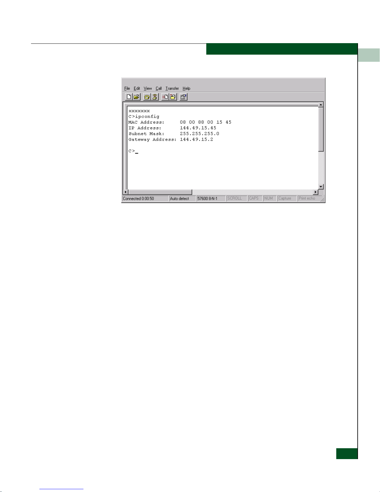
Figure 2-8 Hyperterminal Window
Installation Tasks
2
10. At the C> prompt, type ipconfig and press Enter. The
HyperTerminal window displays with configuration information
listed as follows:
— MAC Address.
— IP Address (default is 10.1.1.10, factory preset is 10.1.1.10).
— Subnet Mask (default is 255.0.0.0).
— Gateway Address (default is 0.0.0.0).
Only the IP Address, Subnet Mask, and Gateway Address fields are
configurable.
11. Change the IP address, subnet mask, and gateway address as
directed by the customer’s network administrator. To change
theswitch network addresses, type the following at the C>
prompt and press Enter.
ipconfig xxx.xxx.xxx.xxx yyy.yyy.yyy.yyy zzz.zzz.zzz.zzz
The IP address is always xxx.xxx.xxx.xxx, the subnet mask is
always yyy.yyy.yyy.yyy, and the gateway address is always
zzz.zzz.zzz.zzz, where the octets xxx, yyy, and zzz are decimals
from zero through 255. If a network address is to remain
unchanged, type the current address in the respective field.
Task 4: Configure Network Information
2-19
Page 94

Installation Tasks
2
When the new network addresses are configured at the switch,
the message Request completed OK displays at the bottom of the
HyperTerminal window.
12. Select Exit from the File menu to close the HyperTerminal
application. The following message box appears:
Figure 2-9 Disconnect Confirmation Message Box
13. Click Ye s. The following message box appears:
2-20
Figure 2-10 Save Session Device Confirmation Box
14. Click No to exit and close the HyperTerminal application.
15. Power off the maintenance terminal:
a. Click the Windows Start button and select the Shut Down
option.
b. At the Shut Down Windows dialog box, select Shut down the
Computer and click Ye s to power off the PC.
16. Disconnect the RS-232 modem cable from the switch and the
maintenance terminal. Replace the protective cap over the
maintenance port.
McDATA® Sphereon 3032 and 3232 Fabric Switches Installation and Service Manual
Page 95

Task 5: LAN-Connect the Switch
Connect the switch to the customer-supplied Ethernet LAN segment
or the Ethernet hub installed in Task 2: Unpack, Inspect, and Install the
Ethernet Hub (Optional).
If the switch is delivered (with the Ethernet hub and management
server) as part of an FC-512 Fabricenter equipment cabinet, this task
and the following two tasks are not required. Go to Task 8: Configure
Management Server Information on page 2-30.
To connect the desktop or rack-mounted switch to the Ethernet LAN
segment:
1. Connect one end of the Ethernet patch cable (supplied with the
switch) to the RJ-45 connector (labeled 10/100) on the left front of
the chassis.
2. Connect the remaining end of the Ethernet cable to the LAN as
follows:
Installation Tasks
2
a. If the switch is installed on a customer-supplied LAN
segment, connect the cable to the LAN as directed by the
customer’s network administrator.
b. If the switch is installed on the Ethernet hub, connect the cable
to any available port (1x through 11x or 13x through 23x) on
the hub.
3. Perform one of the following steps:
— If an management server or customer-supplied server
platform is delivered and available, the Ethernet LAN
segment does not require connection to the internet. Go to Ta s k
6: Unpack, Inspect, and Install the Management Server on
page 2-22.
— If an management server or customer-supplied server
platform is not available and the switch is managed through
the SANpilot interface, attach the Ethernet LAN segment to an
internet connection and go to Task 25: Configure the Switch from
the SANpilot Interface (Optional) on page 2-106
Task 5: LAN-Connect the Switch
2-21
Page 96

Installation Tasks
2
Task 6: Unpack, Inspect, and Install the Management Server
The management server is a1U high, rack-mount unit with the SAN
management application and Sphereon 3032 Switch or Sphereon 3232
Switch element manager applications installed. The applications
provide a graphical user interface (GUI) for operating and managing
the switch and other McDATA products. The management server
also includes a TightVNC Viewer Version 1.2.7 client-server software
control package that provides remote network access (through a
standard web browser) to the server desktop. For information about
the TightVNC Viewer, refer to www.tightvnc.com.
NOTE: The management server and related applications provide a GUI to
monitor and manage McDATA products, and are a dedicated hardware and
software solution that should not be used for other tasks. McDATA tests the
SAN management application installed on the management server, but does
not compatibility test other third-party software. Modifications to the
management server hardware or installation of additional software
(including patches or service packs) may interfere with normal operation.
Unpack, inspect, and install the management server as follows:
1. Inspect the shipping container for damage caused during transit.
If a container is damaged, ensure a representative from the freight
carrier is present when the container is opened.
2. Unpack the shipping container and inspect each item for damage.
Ensure the packaged items correspond to the items listed on the
enclosed bill of materials.
3. If any items are damaged or missing, customers should call the
toll-free telephone number printed on the service label attached
to the bottom of the server.
4. Perform one of the following:
• For a desktop installation, position the management server on
a table or desktop as directed by the customer. Ensure a
grounded AC electrical outlet is available.
• For a cabinet installation, open the rack-mount kit and inspect
the contents. Refer to the enclosed bill of materials and verify
all parts are delivered.
2-22
McDATA® Sphereon 3032 and 3232 Fabric Switches Installation and Service Manual
Page 97
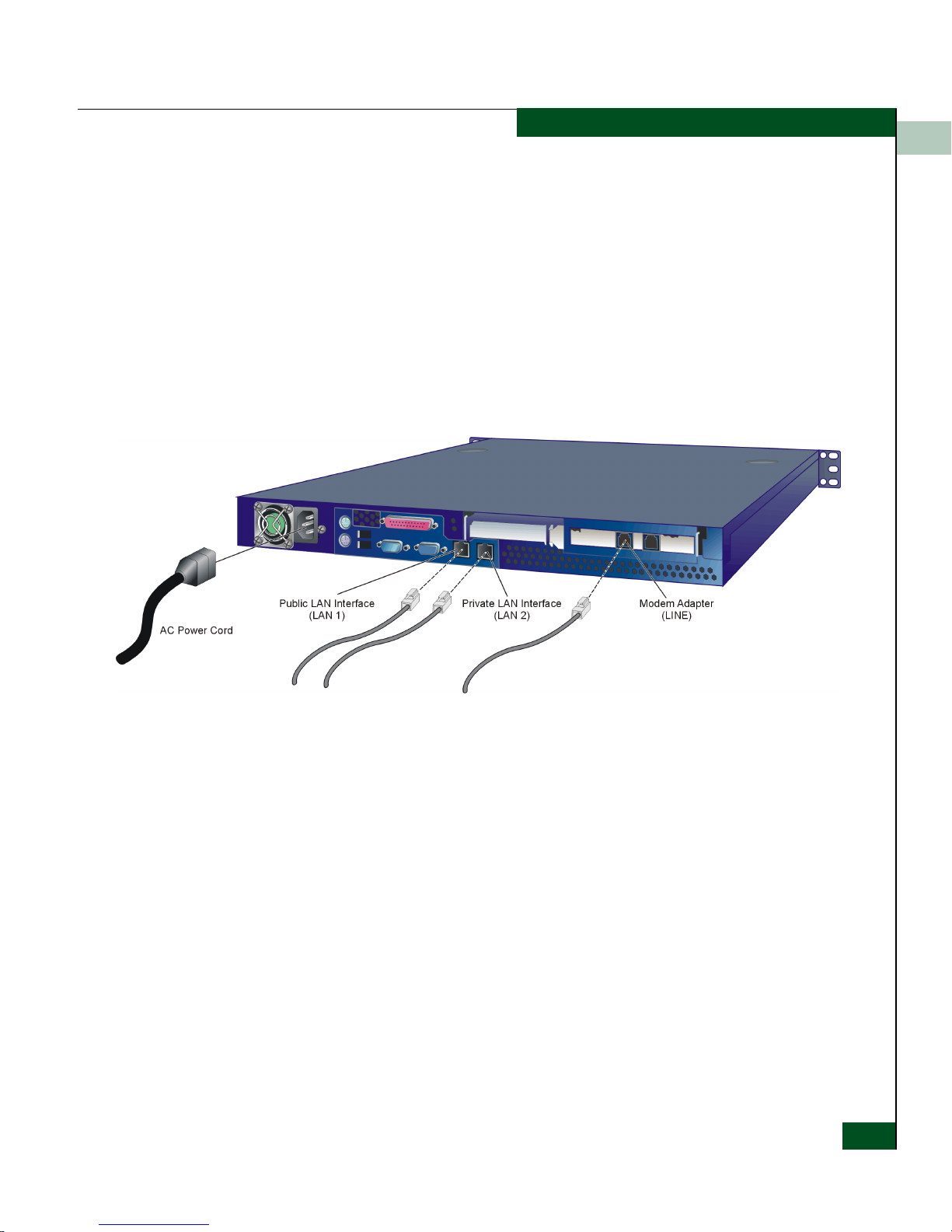
Installation Tasks
Install the management server in the equipment cabinet. Refer
to the 1U Server Rack-Mount Kit Installation Instructions
(958-000310) for guidance.
5. Connect the management server to the customer-supplied
Ethernet
LAN segment or McDATA-supplied Ethernet hub (private LAN
interface). To connect the management server:
a. As shown in Figure 2-11 on page 2-23, connect one end of the
Ethernet patch cable (supplied with the management server)
to the right RJ-45 adapter (LAN 2) at the rear of the server.
2
Figure 2-11 1U Management Server Connections
b. Connect the remaining end of the Ethernet cable to the LAN as
follows:
• If the management server is installed on a
customer-supplied LAN segment, connect the cable to the
LAN as directed by the customer’s network administrator.
• If the management server is installed on the
McDATA-supplied Ethernet hub, connect the cable to any
available hub port.
6. If required, connect the management server to the customer’s
corporate intranet (public LAN interface). To connect the
management server:
a. As shown in Figure 2-11, connect one end of a customer-
supplied Ethernet patch cable to the left RJ-45 adapter (LAN 1)
at the rear of the server.
Task 6: Unpack, Inspect, and Install the Management Server
2-23
Page 98

Installation Tasks
2
b. Connect the remaining end of the Ethernet cable to the
corporate intranet as directed by the customer’s network
administrator.
7. As shown in Figure 2-11, connect the 20-foot phone cord to the
left RJ-11 adapter (LINE) at the rear of the server and to a facility
telephone connection.
8. As shown in Figure 2-11, connect the AC power cord to the server
and to a facility power source or rack power strip that provides
single-phase, 90 to 264 VAC current.
9. When the power cord is connected, the management server
powers on and performs power-on self-tests (POSTs). During
POSTs:
a. The green liquid crystal display (LCD) panel illuminates.
b. The green hard disk drive (HDD) LED blinks momentarily,
and processor speed and random-access memory information
display momentarily at the LCD panel.
c. After a few seconds, the LCD panel displays the following
message pertaining to boot sequence selection (Figure 2-12):
Boot from LAN?
Press <Enter>
Figure 2-12 LCD Panel During Boot Sequence
d. Ignore the message. After ten seconds, the server performs the
boot sequence from the basic input/output system (BIOS).
During the boot sequence, the server performs additional
POSTs and displays the following information at the LCD
panel:
•Host name.
• System date and time.
• LAN 1 and LAN 2 IP addresses.
• Fan 1, fan 2, fan 3, and fan 4 rotational speed.
• Central processing unit (CPU) temperature.
2-24
McDATA® Sphereon 3032 and 3232 Fabric Switches Installation and Service Manual
• Hard disk capacity.
• Virtual and physical memory capacity.
Page 99

Installation Tasks
10. After successful POST completion, the LCD panel displays a
Welcom e!! message and all front panel LEDs extinguish.
11. If a POST error or other malfunction occurs, go to MAP 0000: Start
MAP on page 3-6 to isolate the problem.
12. Press the left edge (PUSH label) of the LCD panel to disengage
the panel and expose the CD-RW drive.
13. Insert a blank rewritable CD into the CD-RW drive and close the
LCD panel.
Task 7: Configure Management Server Password and Network
Addresses
Verify the type of LAN installation with the customer’s network
administrator. If the management server or Fabricenter equipment
cabinet is installed on a dedicated LAN, network information does
not require change. Change the default password for the server’s
LCD panel
(if required by the customer), then go to Task 8: Configure Management
Server Information on page 2-30.
2
If the management server or Fabricenter equipment cabinet is
installed on a public LAN segment, the default password for the
server’s LCD panel and the following transmission control protocol
internet protocol (TCP/IP) network information must be changed to
conform to the customer’s LAN addressing scheme:
• IP address.
•Subnet mask.
NOTE: At some customer installations, TCP/IP addresses for the
management server may be allocated automatically using dynamic host
configuration protocol (DHCP).
Task 7: Configure Management Server Password and Network Addresses
2-25
Page 100

Installation Tasks
2
Configure Password
Figure 2-13 LCD Panel (Password Entry)
To configure a new LCD panel password:
1. At the management server’s LCD panel, press ENTER. The
Welcom e!! or operational information message changes to the
following (Figure 2-13):
Input Password:
0****
2. Using the button to increment a digit, the button to
decrement a digit, the button to move the cursor left,
and the button to move the cursor right, input the default
password (9999), and press ENTER. The LAN 1 Setting??
message appears at the LCD panel.
3. Press the button several times until the Change Password?
option appears at the LCD panel, then press ENTER. The
following message appears (Figure 2-14):
New Password:
0****
Figure 2-14 LCD Panel (New Password)
4. Use the arrow keys as described in step 2 to input a new 4-digit
numeric password, then press ENTER. The following message
appears (Figure 2-15):
Save Ch ange?
Yes, Save !!
Figure 2-15 LCD Panel (Save Change)
5. Press ENTER. A Wait a moment! message appears at the LCD
panel, the LCD panel returns to the LAN 1 Setting?? message,
and the password changes.
2-26
McDATA® Sphereon 3032 and 3232 Fabric Switches Installation and Service Manual
 Loading...