

Page 1

Intrepid®6064 Director
Installation and Service Manual
380 Interlocken Crescent Broomfield, CO 80021-3464
Corporate Headquarter s:
Sales E-mail:
sales@mcdata.com
800-545-5773
Web:
www.mcdata.com
P/N 620-000108-930
REV A
Page 2

Record of Revisions and Updates
Revision Date Description
620-000108-100 2/2001 Initial release of the manual
620-000108-200 5/2001 Updates to describe Release 4.1 of the Enter-
620-000108-300 6/2001 Additional updates to describe Release 4.1 of
620-000108-400 11/2001 Updates to describe Release 4.2 of the Enter-
620-000108-500 5/2002 Updates to describe change from 1 to 2 giga-
620-000108-600 9/2002 Updates to describe Release 6.1 of the Enter-
620-000108-700 10/2002 Updates to describe Release 6.2 and 6.3 of the
prise Fabric Connectivity Manager application.
the Enterprise Fabric Connectivity Manager
application.
prise Fabric Connectivity Manager application.
bits/second and Release 6.0 of the Enterprise
Fabric Connectivity Manager application.
prise Fabric Connectivity Manager application.
Enterprise Fabric Connectivity Manager application.
620-000108-800 2/2003 Updates to describe Release 7.1 of the Enter-
prise Fabric Connectivity Manager application.
New cover and new format.
620-000108-801 6/2003 Updates to describe new firmware and software
download procedures from McDATA’s home
page.
620-000108-900 8/2003 Revision of the manual to describe the one unit
(1U) rack-mount server and Release 7.2 of the
Enterprise Fabric Connectivity Manager application.
ii
Intrepid® 6064 Director Installation a n d Service Manual
Page 3

620-000108-910 12/2003 Revision of the manual to describe Release
8.0/8.1 of the Enterprise Fabric Connectivity
Manager application. New style for safety
notices. Addition of translated safety notices.
620-000108-920 11/2004 Revision of the manual to describe Release 8.5
of the Enterprise Fabric Connectivity Manager
application, and the 10 Gbps (XPM) port card
and functionality.
620-000108-930 7/2005 Revision of the manual to describe Release 8.7
of the Enterprise Fabric Connectivity Manager
(EFCM) and EFCM Basic Edition application
and functionality.
Copyright © 2000-2005 McDATA Corporation. All rights reserved.
Printed July 2005
Twelfth Edition
No part of this publication may be reproduced or distributed in any form or by anymeans, or stored in a
database or retrieval system, without the prior written consent of McDATA Corporation.
The information contained in this document is subject to change without notice. McDATA Corporation
assumes no responsibility for any errors that may appear.
All computer software programs, including but not limited to microcode, described in this document are
furnished under a license, and may be used or copied only in accordance with the terms of such license.
McDATA eitherowns or has theright to licensethe computer softwareprograms described inthis document.
McDATA Corporation retains all rights, title and interest in thecomputer software programs.
McDATA Corporation makesno warranties, expressed or implied,by operation of law or otherwise, relating
to this document, the products or the computer software programs described herein. McDATA
CORPORATION DISCLAIMS ALL IMPLIED WARRANTIES OF MERCHANTIBILITY AND FITNESS FOR
A PARTICULAR PURPOSE. In no event shall McDATA Corporation be liable for (a) incidental, indirect,
special, or consequential damages or (b) any damages whatsoever resulting from the loss of use, data or
profits, arising out of this document, even if advised of the possibility of such damages.
Intrepid® 6064 Director Installation and Service Manual
iii
Page 4

iv
Intrepid® 6064 Director Installation a n d Service Manual
Page 5

Contents
Preface..........................................................................................................................xvii
Chapter 1 General Information
Director Description .........................................................................1-1
Field-Replaceable Units ...................................................................1-4
Cable Management As sembly .................................................1-5
Front Bezel..................................................................................1-5
CTP2 Card...................................................................................1-5
UPM Card...................................................................................1-7
SFP Transceivers........................................................................1-8
Power Supply.............................................................................1-9
RFI Shield....................................................................................1-9
Power Module Assembly.......................................................1-10
Fan Module...............................................................................1-10
SBAR Assembly .......................................................................1-10
Backplane..................................................................................1-11
Error-Detection, Reporting, and Serviceability Features ..........1-11
Element Manager Status Indicators .............................................1-13
Tools and Test Equipment..............................................................1-14
Tools Supplied with the Director...........................................1-14
Tools Supplied by Service Personnel....................................1-16
Director Management ....................................................................1-17
Chapter 2 Installation Tasks
Factory Defaults ................................................................................2-1
Installation Task Summary..............................................................2-3
Task 1: Verify Installation Requirements.......................................2-5
Task 2: Unpack, Inspect, and Install the Ethernet Hub (Optional).
Contents
v
Page 6

Contents
2-6
Unpack and Inspect Ethernet Hub .........................................2-6
Desktop Installation ..................................................................2-7
Rack-Mount Installation...........................................................2-8
Task 3: Unpack, Inspect, and Install the Director.........................2-9
Task 4: Configure Director at the EFCM Basic Edition Interface
(Optional).........................................................................................2-12
Configure Director Identification..........................................2-13
Configure Date and Time....................................................... 2-14
Configure Parameters.............................................................2-15
Configure Fabric Parameters ................................................. 2-17
Configure Network Information...........................................2-18
Configure Basic Port Information .........................................2-20
Configure Port BB_Credit ......................................................2-21
Configure Port NPIV...............................................................2-21
Configure SNMP .....................................................................2-22
Enable CLI ................................................................................2-23
Enable or Disable Host Control.............................................2-24
Configure SSL Encryption......................................................2-25
Install PFE Key s (Optional)....................................................2-26
Configure Security...................................................................2-28
Configure Interswitch Links ..................................................2-30
Task 5: Configure Director Network Information (Optional) ..2-30
Task 6: Unpack, Inspect, and Install the Management Server..2-34
Task 7: Configure Server Password and Network Addresses..2-36
Configure Password................................................................2-36
Configure Private LAN Addresses.......................................2-37
Configure Public LAN Addresses (Optional).....................2-38
Task 8: Config ure Management Server Information .................2-38
Access the M anagement Server Desktop.............................2-38
Configure Management Server Names................................2-39
Configure Gateway and DNS Server Addresses................2-40
Task 9: Configure Windows Operating System Users ..............2-42
Change Default Administrator Password ...........................2-42
Add a N ew User......................................................................2-42
Change User Properties..........................................................2-43
Task 10: Set Management Server Date and Time .......................2-44
Task 11: Configure the Call-Home Feature (Optional)..............2-46
Task 12: Assign User Names and Passwords .............................2-47
Task 13: Configure the Director to the Management Application..
2-48
Task 14: Record or Verify Server R estore Information ..............2-49
Task 15: Verify Director-to-Server Communication...................2-50
vi
Intrepid® 6064 Director Installation and Service Manual
Page 7

Contents
Task 16: Configure PFE Key (Optional) ......................................2-51
Task 17: Config ure Management Server (Optional)..................2-53
Task 18: Set Director Date and Time............................................2-54
Task 19: Configure the Element Manager Applicatio n............. 2-55
Configure Director Identification.........................................2-56
Configure Director Parameters.............................................2-56
Configure Fabric Parameters.................................................2-58
Configure Ports .......................................................................2-60
Configure SNMP.....................................................................2-61
Configure Threshold Alerts...................................................2-62
Enable EFCM Basic E dition and Telnet Access .................. 2-65
Configure, Enable, and Test E-mail Notification ............... 2-65
Configure and Enable Ethernet Events................................2-67
Configure, Enable, and Test Call-Home Event Notification ....
2-67
Configure Security.................................................................. 2-68
Configure Interswitch Links..................................................2-69
Task 20: Back Up Configuration Data .........................................2-70
Task 21: Cable Fibre Channel Ports .............................................2-73
Task 22: Configure Zoning (Optional) ........................................2-73
Task 23: Connect Director to a Fabric Element (Optional)....... 2-74
Task 24: Regis ter with the McDATA Filecenter .........................2-75
Chapter 3 Maintenance Analysis Procedures (MAPS)
Factory Defaults ............................................................................... 3-1
Quick Start......................................................................................... 3-2
MAP 0000: Start MAP......................................................................3-8
MAP 0100: Power Distribution Analysis....................................3-13
MAP 0200: POST Failure Analysis .............................................. 3-16
MAP 0300: Loss of Server Communication................................3-20
MAP 0400: FRU Failure Analysis.................................................3-30
MAP 0500: Port Failure or Link Incident Analysis.................... 3-34
MAP 0600: Fabric or ISL Problem Analysis ...............................3-48
Chapter4 RepairInformation
Factory Defaults ........................................................................4-2
Procedural Notes.......................................................................4-2
Obtaining Log Information.............................................................4-3
SAN Management Logs...........................................................4-3
Element Manager Logs ............................................................ 4-5
EFCM Basic Edition Logs......................................................... 4-8
Contents
vii
Page 8

Contents
Obtaining Port Diagnostic Information.......................................4-11
Port LED D iagnostics..............................................................4-11
Element Manager Application Diagnostics.........................4-12
EFCM Basic Edition Diagnostics...........................................4-17
Performing Loopback Tests...........................................................4-21
Internal Loopback Test (Element Manager Application)..4-21
External Loopback Test (Element Manager Application) .4-23
Internal Loopback Test (EFCM Basic Edition) ....................4-24
External Loopback Test (EFCM Basic Edition) ...................4-26
Blocking and Unblocking Ports....................................................4-27
BlockorUnblockaPortorPortCard(ElementManagerAp-
plication)...................................................................................4-27
Block or Unblo ck a Port (EFCM Basic Edition)...................4-28
Swapping Ports...............................................................................4-29
Performing Channel Wrap Tests (FICON)..................................4-31
Collecting Maintenance Data........................................................4-32
Collecting Maintenance Data (Element Management Appli-
cation)........................................................................................4-32
Collecting Maintenance Data (EFCM Basic Edition)..........4-33
Powering the Director On or Off..................................................4-34
Power-On Procedure ..............................................................4-34
Power-Off Procedure ..............................................................4-35
Setting the Director Online or Offline..........................................4-36
Set Online or Offline (Element Manager Application) ......4-36
Set Online or Offline (EFCM Basic Edition) ........................4-37
IML, IPL, or Reset the Director.....................................................4-38
IML the Director (CTP Front Panel) .....................................4-38
IPL the Director (Element Manager Application) ..............4-39
Reset the Director (CTP Front Panel) ..................................4-39
Cleaning Fiber-Optic Components ..............................................4-40
Downloading Director Firmware and Software ........................4-41
Download Firmware and Software from Filecenter ..........4-42
Download Firmware and Software to Director (Element
Manger Application)...............................................................4-44
Download Firmware and Software to Director (EFCM Basic
Edition)......................................................................................4-46
Installing or Upgrading Software................................................. 4-47
Managing Configuration Data......................................................4-50
Back Up Configuration (Element Manager Application)..4-50
Restore Configuration (Element Manager Application)....4-50
Reset Configuration Data (Element Manager Application).....
4-51
Back Up Conf iguration (EFCM Basic Edition)....................4-54
viii
Intrepid® 6064 Director Installation and Service Manual
Page 9

Restore Configuration (EFCM Basic Edition) .....................4-54
Reset Configuration Data (EFCM Basic Edition) ...............4-55
Chapter 5 Removal and Replacement Procedures (RRPs)
Factory Defaults ........................................................................5-1
Procedural Notes.......................................................................5-2
Removing and Replacing FRUs.....................................................5-3
ESD Information........................................................................5-3
Concurrent FRUs.......................................................................5-5
Nonconcurrent FRUs................................................................5-5
RRP: Cable Management Assembly..............................................5-6
RRP: CTP2 Card............................................................................... 5-8
RRP: Port Module Card (UPM)....................................................5-13
RRP: Optical Transceiver (SFP) ....................................................5-18
RRP: Filler Blank (UPM)................................................................5-22
RRP: Power Supply........................................................................5-24
RRP: RFI Shield...............................................................................5-28
RRP: SBAR Assembly....................................................................5-29
RRP: Fan Module ...........................................................................5-33
RRP: Power Module A ss embly ....................................................5-37
RRP: Backplane ...............................................................................5-41
Contents
Chapter 6 Illustrated Parts Breakdown
Front-Accessible FRUs.....................................................................6-2
Rear-Accessible FRUs ......................................................................6-4
Miscellaneous Parts .........................................................................6-6
Power Cords and Receptacles........................................................6-8
Appendix A Event Code Tab les
System Events (000 through 1 99) .................................................A-3
Power Supply Events (200 through 299) ...................................A-25
Fan Module Even ts (300 through 399) ......................................A-29
CTP/CTP2 Card Events (400 through 499) ..............................A-37
Port Card (UPM) Events (500 through 599) ..............................A-50
SBAR Events (600 through 699) .................................................A-62
Thermal Events (800 through 899) .............................................A-66
Appendix B Director Specifications
Physical Characteristics............................................................B-1
Shipping and Storage Environment.......................................B-2
Contents
ix
Page 10

Contents
Operating Environment........................................................... B-2
Fabricenter Equipment Cabinet Service Clearances............B-3
Appendix C Management Server and Ethernet H ub
Management Server Description...................................................C-1
Management Server Specifications........................................C-2
Ethernet Hub Description ..............................................................C-2
Appendix D Restore Management Server
Requirements ...................................................................................D-1
Restore M anagement Server Procedure ......................................D-2
Appendix E Safety Notices (Multi-Lingual Translations)
Glossary
........................................................................................................................g-1
Index ................................................................................................................................i-1
x
Intrepid® 6064 Director Installation and Service Manual
Page 11

Figures
1-1 Cabinet-Mounted Intrepid 6064 Directors and Management Server ... 1-3
1-2 Director FRUs (Front Access) ..................................................................... 1-4
1-3 Director FRUs (Rear Access) ....................................................................... 1-5
1-4 UPM Card LEDs and Connectors .............................................................. 1-8
1-5 Small Form-Factor Pluggable (SFP) transceiver ...................................... 1-9
1-6 Torque Tool and Hex Adapter ................................................................. 1-15
1-7 Door Key ...................................................................................................... 1-15
1-8 Loopback Plug ............................................................................................ 1-15
1-9 Fiber-Optic Protective Plug ....................................................................... 1-16
1-10 Null Modem Cable ..................................................................................... 1-16
2-1 Patch Cable and MDI Selector Configuration .......................................... 2-8
2-2 Mounting Bracket Installation (Ethernet Hub) ........................................ 2-8
2-3 AC Power Connections (Director) ........................................................... 2-11
2-4 Identification View ..................................................................................... 2-14
2-5 Date Time View .......................................................................................... 2-15
2-6 Parameters View ......................................................................................... 2-15
2-7 Fabric Parameters View ............................................................................. 2-17
2-8 Network View ............................................................................................. 2-19
2-9 Basic Information View ............................................................................. 2-21
2-10 SNMP View ................................................................................................. 2-22
2-11 CLI View ...................................................................................................... 2-24
2-12 OSMS View .................................................................................................. 2-24
2-13 SSL View ...................................................................................................... 2-26
2-14 Maintenance Feature Installation View .................................................. 2-28
2-15 Connection Description Dialog Box ........................................................ 2-32
2-16 1U Management Server Connections ...................................................... 2-35
2-17 Identification Changes Dialog Box .......................................................... 2-40
2-18 Internet Protocol (TCP/IP) Properties Dialog Box ................................ 2-41
Figures
xi
Page 12

Figures
2-19 Add New User Wizard ............................................................................... 2-43
2-20 Properties Dialog Box (General Tab) ........................................................ 2-44
2-21 Date/Time Properties Dialog Box (Time Zone Tab) .............................. 2-45
2-22 Date/Time Properties Dialog Box (Date & Time Tab) .......................... 2-46
2-23 Add User Dialog Box .................................................................................. 2-47
2-24 Address Properties Dialog Box (IP Address Page) ................................ 2-49
2-25 New Feature Key Dialog Box .................................................................... 2-53
2-26 Configure Date and Time D ialog Box ...................................................... 2-54
2-27 Configure Identification Dialog Box ........................................................ 2-56
2-28 Configure Switch Parameters Dialog Box ............................................... 2-57
2-29 Configure Fabric Parameters Dialog Box ................................................ 2-58
2-30 Configure Ports Dialog Box ....................................................................... 2-60
2-31 Configure SNMP Dialog Box .................................................................... 2-62
2-32 New Threshold Alert Dialog Box (Screen 1) ........................................... 2-63
2-33 New Threshold Alert Dialog Box (Screen 2) ........................................... 2-64
2-34 New Threshold Alert Dialog Box (Screen 3) ........................................... 2-65
2-35 Email Event Notification Setup Dialog Box ............................................ 2-66
2-36 InCD Icon (Unformatted CD) .................................................................... 2-71
2-37 McDATA Filecenter Home Page .............................................................. 2-76
3-1 Daisy-Chained Ethernet Hubs .................................................................. 3-24
3-2 UPM Card Diagram (OSI) .......................................................................... 3-44
3-3 UPM Card Diagram (FICON) ................................................................... 3-44
4-1 Port List View .............................................................................................. 4-13
4-2 Port Properties D ialog Box ........................................................................ 4-15
4-3 Port Technology Dialog Box ...................................................................... 4-17
4-4 Port List View .............................................................................................. 4-18
4-5 Port Diagnostics Dialog Box ...................................................................... 4-22
4-6 Diagnostics View ......................................................................................... 4-25
4-7 Basic Information View .............................................................................. 4-29
4-8 Swap Ports D ialog Box ............................................................................... 4-30
4-9 Save Data Collecti on Dialog Box .............................................................. 4-32
4-10 System Files View ....................................................................................... 4-33
4-11 Set Online State Dialog Box ....................................................................... 4-37
4-12 Switch View ................................................................................................. 4-37
4-13 Clean Fiber-Optic Components ................................................................ 4-41
4-14 McDATA Filecenter Home Page .............................................................. 4-42
4-15 Firmware Library Dialog Box .................................................................... 4-44
4-16 Firmware Upgrade View ........................................................................... 4-46
4-17 InstallShield Wizard Dialog Box ............................................................... 4-48
4-18 Backup and Restore Configuration Dialog Box ...................................... 4-50
4-19 Reset Configuration Dialog Box ................................................................ 4-51
xii
Intrepid® 6064 Director Installation a n d Service Manual
Page 13

4-20 Discover Setup Dialog Box ........................................................................ 4-52
4-21 Address Properties Dialog Box ................................................................ 4-53
4-22 Backup Configuration View ..................................................................... 4-54
4-23 Restore Configuration View ..................................................................... 4-55
5-1 ESD Grounding Point (Front) ..................................................................... 5-4
5-2 ESD Grounding Point (Rear) ...................................................................... 5-4
5-3 Cable Management Assembly Removal and Replacement .................... 5-7
5-4 CTP2 Card Removal and Replacement ..................................................... 5-9
5-5 UPM Card Removal and Replacement ................................................... 5-15
5-6 SFP Optical Transceiver Removal and Replacement ............................ 5-19
5-7 Filler Blank Removal and Replacement .................................................. 5-23
5-8 Power Supply Removal and Replacement ............................................. 5-25
5-9 RFI Shield Removal and Replacement .................................................... 5-28
5-10 SBAR Assembly Removal a n d Replacement .......................................... 5-30
5-11 Fan Module Removal and Replacement ................................................. 5-34
5-12 Power Module Assembly Removal and Replacement .......................... 5-38
5-13 Backplane Removal and R eplacement .................................................... 5-43
5-14 Connection Description Dialog Box ........................................................ 5-46
5-15 Connect To Dialog Box .............................................................................. 5-46
5-16 COMn Dialog Box ...................................................................................... 5-47
5-17 HyperTerminal Dialog Box ....................................................................... 5-48
5-18 HyperTerminal Dialog Box ....................................................................... 5-48
Figures
6-1 Front-Accessible FRUs ................................................................................. 6-2
6-2 Rear-Accessible FRUs .................................................................................. 6-4
6-3 Miscellaneous Parts ...................................................................................... 6-6
6-4 Power Cords and Receptacles .................................................................... 6-8
C-1 Management Server ..................................................................................... C-1
C-2 24-Port Ethernet Hub ................................................................................... C-3
D-1 Run Dialog Bo x ............................................................................................ D-4
D-2 VNC Authentication Screen ....................................................................... D-5
D-3 Welcome to Windows D ialog Box ............................................................ D-5
D-4 Log On to Windows Dialog Box ............................................................... D-6
D-5 EFCM Log In or SANavigator Log In Log In Dialog Box ...................... D-6
Figures
xiii
Page 14

Figures
xiv
Intrepid® 6064 Director Installation a n d Service Manual
Page 15

Tables
1-1 Element Manager Alert Symbols, Messages, and Status ...................... 1-13
2-1 Factory-Set Defaults (Director) ................................................................... 2-1
2-2 Factory-Set Defaults (Management Server) .............................................. 2-2
2-3 Installation Task Summary ......................................................................... 2-3
2-4 Operational States and Symbols ............................................................... 2-51
3-1 Factory-Set Defaults ..................................................................................... 3-1
3-2 MAP Summary ............................................................................................. 3-2
3-3 Event Codes versus Maintenance Action ................................................. 3-2
3-4 MAP 100 Even t Codes ............................................................................... 3-13
3-5 MAP 200 Even t Codes ............................................................................... 3-16
3-6 MAP 200: Byte 0 FRU Codes ..................................................................... 3-16
3-7 MAP 300 Erro r Messages .......................................................................... 3-22
3-8 MAP 400: Event Codes .............................................................................. 3-30
3-9 MAP 500: Event Codes .............................................................................. 3-34
3-10 Link Incident Messages ............................................................................. 3-35
3-11 Invalid Attachment Reasons a nd Actions ............................................... 3 -36
3-12 Inactive Port Reasons an d Actions ........................................................... 3-41
3-13 MAP 600 Event Codes ............................................................................... 3-48
3-14 E_Port Segmentation Reasons and Actions ............................................ 3-50
3-15 Port Fence Codes and Actions .................................................................. 3-55
3-16 Fabric Merge Failure Reasons and Actions ............................................ 3-58
4-1 Factory-Set Defaults ..................................................................................... 4-2
4-2 Port Operational States .............................................................................. 4-11
5-1 Factory-Set Defaults ..................................................................................... 5-1
5-2 Concurrent FRUs .......................................................................................... 5-5
Tables
xv
Page 16

Tables
5-3 Nonconcurrent FRUs .................................................................................... 5-5
6-1 Front-Accessible FRU Parts List .................................................................. 6-3
6-2 Rear-Accessible FRU Parts List ................................................................... 6-5
6-3 Miscellaneous Parts ...................................................................................... 6-7
6-4 Power Cord and Receptacle List ................................................................. 6-9
xvi
Intrepid® 6064 Director Installation a n d Service Manual
Page 17

Preface
This publication is part of a documentation suite that supports the
McDATA® Intrepid® 6064 Director.
Who Should Use This
Manual
Organization of This
Manual
This publication is intended for installation and service
representatives experienced with the director, storage area network
(SAN) technology, and Fibre Channel technology.
This publicationincludessix chapters and four appendicesorganized
as follows:
Chapter 1, General Information.Thischapterdescribesthedirector,
including field-replaceable units (FRUs), controls, connectors,
and indicators, and director specifications. The chapter also
describes the maintenance approach, director management
through the Enterprise Fabric Connectivity (EFC) Server, EFCM
Basic Edition interface, or a remote workstation, error detection
and reporting features, serviceability features, software
diagnostic features, and tools and test equipment.
Chapter 2, Installation Tasks. This chapter describes tasks to install,
configure, and verify operation of the director, optional Ethernet
hub, and m anagement server.
Chapter 3, Maintenance Analysis Procedures (MAPS). This chapter
describes maintenance analysis procedures (MAPs) to fault
isolate a director problem to an individual FRU.
Chapter 4, Repair Information. This chapter describes
supplementary diagnostic and repair procedures for a failed
director. The chapter includes procedures to display and use log
information, perform port diagnostics, manage configuration
Intrepid® 6064 Director Installation and S ervice Manual
xvii
Page 18

Preface
data, collect maintenance data, power-on, power-off, and reset
the director, set the director online or offline, block ports, manage
director firmware, clean fiber optics, and install or upgrade
management server software.
Chapter 5, Removal and Replacement Procedures (RRPs).This
chapter describes procedures to remove and replace director
FRUs.
Chapter 6, Illustrated Parts Breakdown. This chapter illustrates,
describes, and shows the location of director FRUs. In addition,
FRUs are cross-referenced to corresponding part numbers.
Appendix A, Event Code Tables This appendix provides an
explanation of event codes that appear at the Element Manager
application or EFCM Basic Edition interface. The event severity
andarecommendedcourseofactioninresponsetoeacheventare
also provided.
Appendix B, Director Specifications. This appendix provides the
director specifications including its physical characteristics, and
storage, shipping, and operating environments.
Appendix C, Management Server and Ethernet Hub. This appendix
provides the management-server specifications and a description
of the ethernet hub.
Appendix D, Restore Management Server This appendix provides
the instructions to restore all required director applications to the
management server in case of a hard drive failure.
Appendix E, Safety Notices (Multi-Lingual Translations) This
appendix provides the translation of the safety notices in this
publication.
A Glossary defines terms, abbreviations,and acronyms used in the
manual. An Index is also provided.
xviii
Intrepid® 6064 Director Installation a n d Service Manual
Page 19

Related Publications Other publications that provide additional information about the
director include:
• McDATA Products in a SAN Environment Planning Manual
(620-000124).
• McDATA Intrepid 6140 and 6064 Directors Element Manager User
Manual (620-000153).
• McDATA Enterprise Fabric Connectivity Manager User Manual
(620-005001).
• McDATA EFCM Basic Edition User Manual (620-000160).
• McDATA SNMP Support Manual (620-000131).
• McDATA E/OS Command Line Interface User Manual (620-000134).
• McDATA Rack-Mount Kit, Intrepid 6064 Director in Fabricenter
(FC-512) Cabinet, Installation Instructions (958-000270).
• McDATA EFCM Lite Installation Instructions (958-000171).
Preface
• 1U Server Rack-Mount Kit Installation Instructions (958-000310).
• SANavigatorUserGuide(621-000013).
• McDATA FC-512 Fabricenter Equipment Cabinet Installation and
Service Manual (620-000100).
Ordering Printed
Manuals
To order a printed copy of this publication, contact your McDATA
representative or contact McDATA at the phone number or fax
number listed below.
Phone: (800) 545-5773 and select the option for information about
McDATA’s complete family of enterprise-to-edge SAN solutions.
Fax: (720) 558-4193
Where to Get Help For technical support, contact the McDATA Solution Center. The
center provides a single point of contact, and is staffed 24 hours a day,
seven days a week, including holidays. Contact the center at the
phone number, fax number, or e-mail address listed below. Please
have the product serial number (printed on the service label attached
to the director) available.
Phone: (800) 752-4572 or (720) 566-3910
Fax: (720) 566-3851
E-mail: support@mcdata.com
Intrepid® 6064 Director Installation and S ervice Manual
xix
Page 20

Preface
For technical support for the SANavigator®application, contact the
SANavigatorSolutionCenteratthephonenumberore-mailaddress
listed below.
Phone: (877) 948-4448
E-mail: support@sanavigator.com
Forwarding
Publication
Comments
We welcome commentsabout this publication. Please send comments
to the McDATA Solution Center by telephone, fax, or e-mail. The
numbers and e-mail address are listed above. Please identify the
manual, page numbers, and details.
Trademarks The following terms, indicated by a registered trademark symbol
(®) or trademark symbol (™) on first use in this publication, are
trademarks of McDATA Corporation or SANavigator, Inc. in the
United States or other countries or both:
Registered Trademarks
McDATA
Intrepid
Fabricenter
OPENready
EFCM Basic Edition
SANtegrity
®
®
®
®
®
®
Trademarks
Sphereon™
Fibre Channel Director™
SANavigator®HotCAT™
OPENconnectors™
EON™
All other trademarked terms, indicated by a registered trademark
symbol (®) or trademark symbol (™) on first use in this publication,
are trademarks of their respective owners in the United States or
other countries or both.
Laser Compliance
Statement
xx
Intrepid® 6064 Director Installation a n d Service Manual
Laser transceivers for the director are tested and certified in the
United States to conform to Title 21 of the Code of Federal
Regulations (CFR), Subchapter J, Parts 1040.10 and 1040.11 for Class 1
laser products. Elsewhere, the transceivers are tested and certified to
be compliant with International Electrotechnical Commission
IEC825-1 and European Norm EN60825-1 and EN60825-2 regulations
for Class 1 laser products. Class 1 laser products are not considered
hazardous. The transceivers are designed such that there is never
human access to laser radiation above a Class 1 level during normal
operation or prescribed maintenance conditions.
Page 21

Preface
Federal
Communications
Commission (FCC)
Statement
Chinese Class A
Telecommunication
Product Statement
The director generates, uses, and can radiate radio frequency energy,
and if not installed and used in accordance with the instructions
provided, may cause interference to radio communications. The
directors have been tested and found to comply with the limits for
Class A computing devices pursuant to Subpart J of Part 15 of the
FCC Rules, which are designed to provide reasonable protection
against such interference in a commercial environment. Operation of
this equipment in a residential area is likely to cause interference in
which case the user, at his or her own expense, will take whatever
measures are required to correct the interference. Any modifications
or changes made to the director without explicit approval from
McDATA, by means of a written endorsement or through published
literature, will invalidate the service contract and void the warranty
agreement with McDATA.
European Union
Conformity
Declarations for
Information
Technology
Equipment
European Union
Directives
The director meets the following regulatory requirements as set forth
by European Norms (ENs) and relevant International
Electrotechnical Commission (IEC) standards for commercial and
light industrial information technology equipment (ITE).
• EN55022: 1998; EN55024: 1997, +A1: 1998: ITE-generic radio
frequency interference (RFI) emission standard for domestic,
commercial, and light industrial environments.
• EN60950: ITE-generic electrical and fire safety standard for
domestic, commercial, and light industrial environments.
The European Union (EU) Council has implemented a series of
directives that define product safety standards for all EU member
countries. The following directives apply to the director:
• The director conforms with all protection requirements of E U
directive 89/336/EEC (EMC Directive) in accordance with of the
laws of the member countries relating to electromagnetic
compatibility (EMC), emissions, and immunity.
Intrepid® 6064 Director Installation and S ervice Manual
xxi
Page 22
Preface
• The director conforms with all protection requirements of E U
directive 73/23/EEC (Low Voltage Directive) in accordance with
of the laws of the member countries relating to electrical safety.
• The director conforms with all protection requirements of E U
directive 93/68/EEC (Machinery Di rective) in accordance with of
the laws of the member countries relating to safe electrical and
mechanical operation of the equipment.
McDATA does not accept responsibility for any failure to satisfy the
protection requirements of any of these directives resulting from a
non-recommended or non-authorized modification to the director.
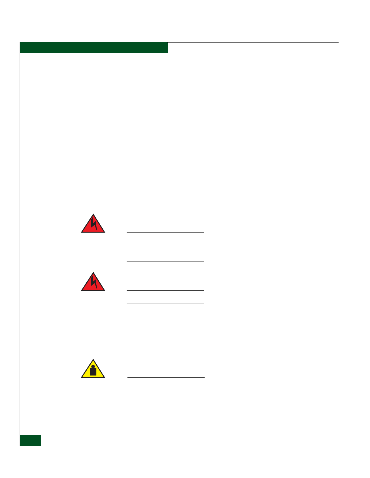
Dangers and Cautions The following DANGER statements appear in this publication and
describe safety practices that must be observed while installing or
servicing the director. A DANGER statement provides essential
information or instructions for which disregard or noncompliance
may result in death or severe personal injury.
DANGER
Use the supplied power cords. Ensure the facility power receptacle is
the correct type, supplies the required voltage, and is properly
grounded.
DANGER
Disconnect the power cords.
The following CAUTION statementappearsinthispublicationand
describes safety practices that must be observed while installing or
servicing the director. A CAUTION statement provides essential
information or instructions for which disregard or noncompliance
may result in personal injury.
CAUTION
Use safe lifting practices when moving the product.
General Precautions When installing or servicing the director, follow these practices:
xxii
Intrepid® 6064 Director Installation a n d Service Manual
•Alwaysusecorrecttools.
Page 23

• Always use correct replacement parts.
• Keep all paperwork up to date, complete, and accurate.
ESD Precautions The director contains electrostatic discharge (ESD) sensitive FRUs.
When working with any director FRU, always use correct ESD
procedures.
• Always wear a wrist grounding strap connected to chassis
ground (if the director is plugged in) or a bench ground.
• Always store ESD-sensitive components in antistatic packaging.
Preface
Intrepid® 6064 Director Installation and S ervice Manual
xxiii
Page 24

Preface
xxiv
Intrepid® 6064 Director Installation a n d Service Manual
Page 25

1
General Information
The McDATA®Intrepid™ 6064 Director provides up to 64 ports of
high-performance, dynamic Fibre Channel connectivity for switched
fabric devices in a storage area network (SAN). The director provides
a scalable bandwidth (1 or 2 gigabits per second), redundant
switched data paths, and long transmission distances.
This chapter presents information and features of the director and its
management, including:
Director Description
• Director description.
• Field-replaceable units (FRUs).
• Error detection, reporting, and serviceability features.
• Element Manager status indicators
• Tools and test equipment.
• Director management.
The Intrepid 6064 Director is a 64-port product that provides dynamic
switched connections between Fibre Channel servers and devices in a
SAN environment. The ports operate at either 1 or 2 gigabits per
second(Gbps).Directors(fromonetofour)canbeconfiguredto
order in a McDATA-supplied FC-512 Fabricenter™ equipment
cabinet, which can provide up to 256 ports in a single cabinet.
The director provides dynamic switched connections for servers and
devices, supports mainframe and open-systems interconnection (OSI)
GeneralInformation
1-1
Page 26

General Information
1
computing environments, and provides data transmission and flow
control between device node ports (N_Ports) as dictated by the Fibre
Channel Physical and Signaling Interface (FC-PH 4.3). Through
interswitch links (ISLs), the director can also connect to one or more
additional directors to form a Fibre Channel multiswitch fabric.
The director can be managed through a rack-mount management
server running a Java™-based SAN management application
®
(SANavigator
and the Intrepid 6064 Element Manager application.
Multiple directors and the management server communicate on a
local area network (LAN) through one or more 10/100 Base-T
Ethernet hubs. One or more 24-port Ethernet hubs are optional and
can be ordered with the director. Up to three hubs can be
daisy-chained to provide additional Ethernet connections as more
directors (or other McDATA managed products) are installed on a
customer network.
As an op tion, administrators or operators with a browser-capable PC
and an Internet connection can monitor and manage the director
through the EFCM Basic Edition interface. The EFCM Basic Edition
interface manages only a single director, and provides a graphical
user interface (GUI) that supports product configuration, statistics
monitoring, and basic operation. The EFCM Basic Edition interface is
opened from a standard web browser running Netscape Navigator
4.6orhigherorMicrosoft®Internet Explorer 4.0 or higher.
or Enterprise Fabric Connectivity Manager (EFCM)
®
1-2
Figure 1-1 illustrates an equipment rack with four directors, the
management server, and an Ethernet hub.
Intrepid® 6064 Director Installation a n d Service Manual
Page 27

General Information
1
Figure 1-1 Cabinet-Mounted Intrepid 6064 Directors and Management Server
Director Description
1-3
Page 28
General Information
1
Field-Replaceable Units
The director provides a modular design that enables quick removal
and replacement of FRUs. This section describes director FRUs and
controls, connectors, and indicators associated with the FRUs.
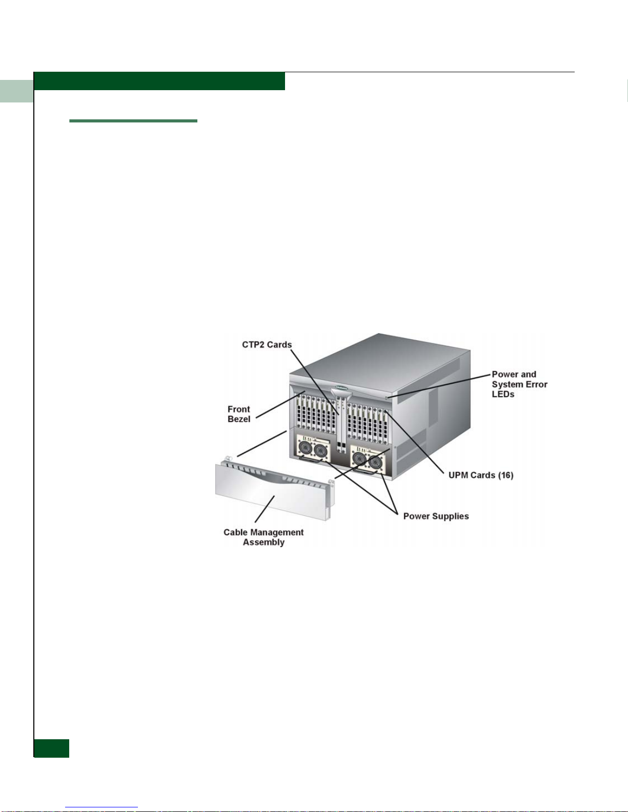
Director FRUs accessed from the front (Figure 1-2)includethe:
• Cable management assembly.
•Frontbezel.
• Control processor (CTP) cards.
• Universal port module (UPM) cards (1 and 2 Gbps).
• Power supplies.
Figure 1-2 Director FRUs (Front Access)
1-4
Intrepid® 6064 Director Installation a n d Service Manual
Director FRUs accessed from the rear (Figure 1-3)includethe:
• Power module assembly.
•Fanmodules.
• Serial crossbar (SBAR) assemblies.
• Radio frequency interference (RFI) shield (not shown).
•Backplane(notshown).
Page 29
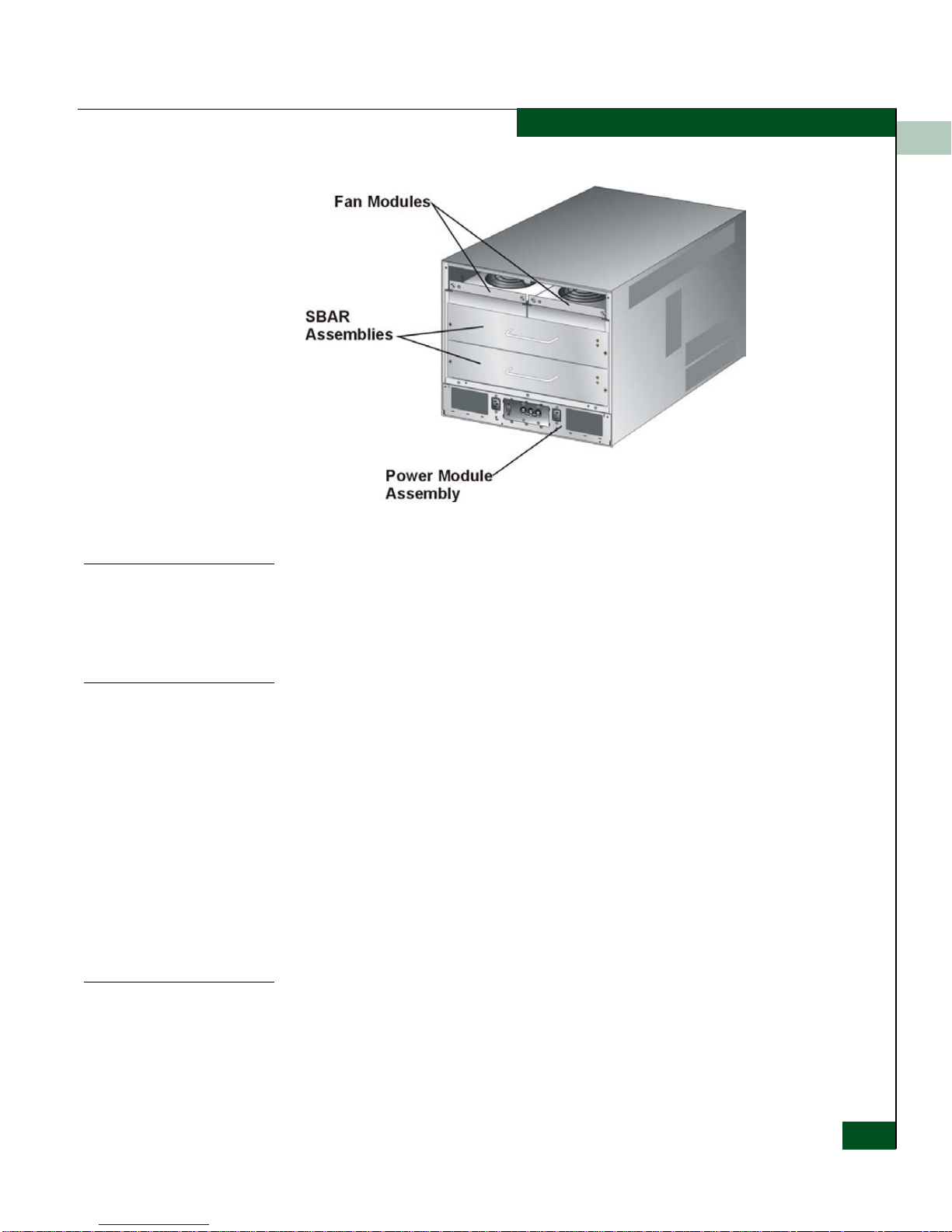
Figure 1-3 Director FRUs (Rear Access)
General Information
1
Cable
Management
Assembly
Front Bezel
CTP2 Card
The cable management assembly at the bottom front of the director
provides routing for Ethernet cables attached to CTP2 cards and
fiber-optic cables attached to director ports. The assembly rotates up
to provide front access to the redundant power supplies.
The bezel at the top front of the director includes an amber system
error light-emitting diode (LED) and a green power LED. The power
LED illuminates when the director is powered on and operational. If
the LED extinguishes, a facility power source, alternating current
(AC) power cord, or director power distribution failure is indicated.
The system error LED illuminates when the director detects an event
requiring immediate operator attention, such as a FRU failure. The
LED remains illuminated as long as an event is active. The LED
extinguishes when the Clear System Error Light function is selected
from the Element Manager application. The LED blinks if unit
beaconing is enabled. An illuminated system error LED (indicating a
failure) takes precedence over unit beaconing.
The director is delivered with two CTP2 cards. The active CTP2 card
initializes and configuresthe director after power on and contains the
microprocessor and associated logic that coo rdinate director
operation.
Field-Replaceable Units
1-5
Page 30

General Information
1
The CTP2 card provides an initial machine load (IML) button and a
RESET button (recessed) on the faceplate.
When the IML button is pressed, held for three seconds, and
released, the director performs an IML that reloads the firmware from
FLASH memory. This operation is not disruptive to Fibre Channel
traffic.
When the RESET button is pressed and held for three seconds, the
director performs a reset. A reset is disruptive and resets the:
• Microprocessor and functional logic for the CTP2 card and
reloads the firmware from FLASH memory.
• Ethernet LAN interface, causing the connection to the
management server to drop momentarily until the connection
automatically recovers.
• Ports,causing all Fibre Channel connections to drop momentarily
until the connections automatically recover. This causes attached
devices to log out and log back in, therefore data frames lost
during director reset must be retransmitted.
A reset should only be performed if a CTP2 card failure is indicated.
As a precaution, the RESET button is flush mounted to protect
against inadvertent activation.
Each CTP2 card also provides a 10/100 megabit per second (Mbps)
RJ-45 twisted pair connector on the faceplate that attaches to an
Ethernet local area network (LAN) to communicate with the
management server or a simple network management protocol
(SNMP) management station.
Each CTP2 card provides system services processor (SSP) and
embedded port (EP) subsystems. The SSP subsystem runs director
applications and the underlying operating system, communicates
with director ports, and controls the RS-232 maintenance port and
10/100 Mbps Ethernet po rt. The EP subsystem provides Class F and
exception frame processing, and manages frame transmission to
and from the SBAR assembly. In addition, a CTP2 card provides
nonvolatile memory for storing firmware, director configuration
information, persistent operating parameters, and memory dump
files. Directorfirmware is upgradedconcurrently (without disrupting
operation).
The backup CTP2 card takes over operation if the active card fails.
Failover from a faulty card to the backup card is transparent to
attached devices.
1-6
Intrepid® 6064 Director Installation a n d Service Manual
Page 31

General Information
Each card faceplate contains a green LED that illuminates if the card
is operational and active, and an amber LED that illuminates if the
card fails. Both LEDs areextinguished on an operational backup card.
The amber LED blinks if FRU beaconing is enabled.
1
UPM Card
Each UPM card (Figure 1-4) provides four full-duplex generic ports
(G_Ports)thattransmitorreceivedataat1or2gigabitspersecond
(Gbps). G_Port functionality depends on the type of cable
attachment. UPM cards use non-open fiber control (OFC) Class 1
laser transceivers that comply with Section 21 of the Code o f Federal
Regulations(CFR),Subpart(J)asofthedateofmanufacture.
The card faceplate contains:
• Four duplex LC connectors for attaching fiber-optic cables.
• AnamberLED(atthetopofthecard)thatilluminatesifanyport
fails or blinks if FRU beaconing is enabled.
• A bank of amber and green LEDs above the ports. One amber
LED and one green LED are associated w ith each port and
indicate port status as follows:
— The green LED illuminates (or blinks if there is active traffic)
and the amber LED extinguishes to indicate normal port
operation.
— The amber LED illuminates and the green LED extinguishes to
indicate a port failure.
— Both LEDs extinguish to indicate a port is operational but not
communicating with an N_Port (no cable attached, loss of
light, port blocked, or link recovery in process).
— The amber LED flashes and the green LED either remains on,
extinguishes, or flashes to indicate a port is beaconing or
running online diagnostics.
Field-Replaceable Units
1-7
Page 32

General Information
1
Figure 1-4 UPM Card LEDs and Connectors
SFP Transceivers
Singlemode or multimode fiber-optic cables attach to director ports
through 1 or 2 Gbps small form-factor pluggable (SFP) optic
transceivers (Figure 1-5). The transceivers provide duplex LC
®
connectors and can be detached from director ports for easy
replacement.
NOTE: SFP and XFP transceivers are not interchangeable.
These fiber-optic transceiver types are available:
• Shortwave laser, SFP, 1.0625 or 2.125 Gbps
• Longwave laser, SFP, 1.0625 or 2.125 Gbps
1-8
Intrepid® 6064 Director Installation a n d Service Manual
Page 33

Figure 1-5 Small Form-Factor Pluggable (SFP) transceiver
General Information
1
Power Supply
RFI Shield
Redundant, load-sharing power supplies step down and rectify
facility input power to provide 48-volt direct current (VDC) power to
director FRUs. The power supplies also provide overvoltage and
overcurrent p rotection. Either power supply can be replaced while
the director is powered on and operational.
Each power supply has a separate backplane connection to allow for
different AC power sources. The power supplies are input rated at 85
to 264 volts alternating current (VAC). The faceplate of each power
supply provides the following status LEDs:
• A green PWR OK LED illuminates if the power supply is
operational and receiving AC power.
•AnamberFAULT LED illuminates if the power supply fails.
•AnamberTEMP LED illuminates if the power supply shuts
down due to an over temperature condition.
•AnamberILIMLED illuminates if the power supply is
overloaded and operating at the current limit (15.6 amperes).
The RFI shield covers and provides RFI protection for all rear- access
FRUs except the power module assembly. The RFI shield is
concurrent and can be removed or replaced while the director is
powered on and operating.
Field-Replaceable Units
1-9
Page 34

General Information
1
Power Module
Assembly
Fan Module
The power module assembly is located at the bottom rear of the
director. The module is a nonconcurrent FRU, and the director must
be powered off prior to scheduled removal and replacement. The
module provides:
• Two single-phase AC power connectors. Each connector is input
rated at 85 to 264 VAC.
• A power switch (circuit breaker) that controls AC power
distribution to both power supplies. The breaker is set manually,
or is automatically tripped by internal software if thermal sensors
indicate the director is overheated.
• A 9-pin maintenance port that provides a connection for a local
terminal or dial-in connectionfor a remote terminal. Although the
port is typically used by maintenance personnel, operations
personnel use the port to configure network addresses.
• An input filter and AC system harness (internal to the FRU) that
provides the wiring to connect the AC power connectors to the
power switch and power supplies (through the backplane).
Two fan modules, each containing three fans (six fans total), provide
cooling for director FRUs, as well as redundancy for conti nued
operationifafanfails.
SBAR Assembly
1-10
Intrepid® 6064 Director Installation a n d Service Manual
A fan module can be replaced while the director is powered on and
operating, provided the module is replaced within ten minutes (after
whichsoftwarepowersoffthedirector).AnamberLEDforeachfan
module illuminates if one or more fans fail or rotate at insufficient
angular velocity.
The directoris delivered with tw o SBAR assemblies.The active SBAR
is responsiblefor Fibre Channel frame transmission from any director
port to any other director port. Connections are established without
software intervention. The assembly accepts a connection request
from a port, determines if a connection can be established, and
establishes the connection if the destination port is available. The
assembly also stores busy, source connection, and error status for
each director port.
The backup SBAR takes over operation if the active assembly fails,
and provides the ability to maintain connectivity and data frame
Page 35

General Information
transmission without interruption. Failover to the backup assembly is
transparent to attached devices.
Each SBAR assembly consistsof a card and steel carriage that mounts
flush on the backplane. The carriage provides protection for the back
of the card, distributes cooling airflow, and assists in aligning the
assembly during installation. The rear of the carriage contains a green
LED that illuminates if the assembly is operational and active, and an
amber LED that illuminates if the assembly fails. Both LEDs are
extinguished on an operational backup assembly. The amber LED
blinks if FRU beaconing is enabled.
1
Backplane
The backplane provides 48 VDC power distribution and connections
for all logic cards. The backplane is a nonconcurrent FRU. The
director must be powered off prior to FRU removal and replacement.
Error-Detection, Reporting, and Serviceability Features
The director provides the following error detection, reporting, and
serviceability features:
• Light-emitting diodes (LEDs) on director FRUs and the front
bezel that provide visual indicators of hardware status or
malfunctions.
• Redundant FRUs (logic cards, power supplies, and cooling fans)
that are removed or replaced without disrupting director or Fibre
Channel link operation.
• A modular design that enables quick removal and replacement of
FRUs without the use of special tools or equipment.
• System alerts and logs that display director, Ethernet link, and
Fibre Channel link status at the management server (running a
SAN management application), client communicating with the
management server, or EFCM Basic Edition interface.
• Diagnostic software that performs power-on self-tests (POSTs)
and port diagnostics (internal loopback, external loopback, and
Fibre Channel (FC) wrap tests). The FC wrap test applies only
when thedirector is configured to operate in FICON management
style.
Error-Detection, Reporting, and Serviceability Features
1-11
Page 36

General Information
1
• An RS-232 maintenance port at the rear of the director (port
access is password protected) that enables installation or service
personnel to change the director’s internet protocol (IP) address,
subnet mask, and gateway address; or to run diagnostics and
isolate system problems through a local or remote terminal.
The director parameters can also be changed through a Telnet
session, access for which is provided through a local or remote PC
with an Internet connection to the director.
• Data collection through the Element Manager application or the
EFCM Basic Edition interface to help isolate system problems.
The data includes a memory dump file and audit, hardware, and
engineering logs.
• Beaconing to assist service personnel in locating a specific port,
FRU, or director in a multiswitch environment. When port
beaconing is enabled, the amber LED associated with the port
flashes. When FRU beaconing is enabled, the amber (service
required) LED on the FRU flashes. When unit beaconing is
enabled, the system error indicator on the front bezel flashes.
Beaconing does not affect port, FRU, or director operation.
• An internal modem for use by support personn el to dial-in to the
management server for event notification and to perform remote
diagnostics.
• Automatic notification of significant system events (to support
personnel or administrators) through e-mail messages or the
call-home feature.
NOTE: Thecall-homefeatureisnotavailablethroughtheEFCMBasic
Edition interface. The call-home feature may not be available ifthe EFCM
Lite application is installed on a customer-supplied platform.
• Concurrent port maintenance. UPM cards are added or replaced
and fiber-optic cables are attached to ports without interrupting
other ports or director operation.
• Status monitoring of redundant FRUs and alternate Fibre
Channel data paths to ensure continued director availability in
case of failover. The SAN management application queries the
status of each backup FRU. A backup FRU failure is indi cated by
an illuminated amber LED.
1-12
Intrepid® 6064 Director Installation a n d Service Manual
Page 37

• SNMP management using the Fibre Channel Fabric Element MIB
(Version 1.1), transmission control protocol/internet protocol
(TCP/IP) MIB-II definition (RFC 1157), or a product-specific
private enterprise MIB that runs on each director. Up to six
authorized managementworkstationscan be configured through
the Element Manager application or EFCM Basic Edition interface
to receive unsolicited SNMP trap messages. The trap messages
indicate operational state changes and failure conditions.
• SNMP management using the Fibre Alliance MIB (Version 3.1)
that runs on the management server. Up to 12 authorized
management workstations can be configured through the SAN
management application to receive unsolicited SNMP trap
messages. The trap messages indicate operational state changes
and failure conditions.
Element Manager Status Indicators
In addition to the visual indicators on the director chassis, the
Element Manager application presents alert symbols and messages
that describe the condition of the director and its FRUs. These alert
symbols, messages, and a description are summarized in Table 1-1.
General Information
1
Table 1-1 Element Manager Alert Symbols, Messages, and Status
Symbol Message Description
Fully operational All components and installed ports are operational.
Redundant failure A redundant component has failed, and the backup
component has taken over.
Minor failure A failure has occurred that has decreased the
director operational capability, but has not affected
normal switching operations.
Major failure Power supplies have failed.
Element Manager Status Ind icato r s
1-13
Page 38

General Information
1
Table 1-1 Element Manager Alert Symbols, Messages, and Status (
Symbol Message Description
Tools and Test Equipment
This section describes tools and test equipment that may be required
to test, service, and verify operation of the director and attached
management server. These tools are either supplied with the director
or must be supplied by service personnel.
continued
Loading firmware The system is busy loading new firmware, but the
system is otherwise operational.
Not operational A critical failure has occurred that prevents the
director from performing fundamental switching
operations.
o Link time-out
oProtocol
mismatch
o Never connected
Director status is unknown. Occurs is network
connection between the management serverand the
director is lost, or if a CTP card fails and there is no
operational backup, or if there is no system power.
)
Tools Supplied with
the Director
The following tools are supplied with the director. Use of the tools
may be required to perform installation, test, service, or verification
tasks.
• Torque tool with hexagonal adapter - Thetorquetoolwith5/32”
hexagonal adapter (Figure 1-6)isrequiredtoremoveandreplace
director logic cards.
ATTENTION! The torque tool supplied with the I ntrepid 6064 Director is
designed to tighten director logic cards and is set to release at a torque value
of six inch-pounds. Do not use an Allen wrench or torque tool designed for
use with another McDATA product. Use of the wrong tool may overtighten
and damage logic cards.
1-14
Intrepid® 6064 Director Installation a n d Service Manual
Page 39

Figure 1-6 Torque Tool and Hex Adapter
• Door key - The door key with 5/16” socket (Figure 1-7)is
required to open the front or rear door o f the FC-512 Fabricenter
equipment cabinet. A 5/16” socket wrench may be used in lieu of
the door key.
General Information
1
Figure 1-7 Door Key
• Loopback plug - An SFP multimode (shortwave laser) or
singlemode (longwave laser) loopback plug (Figure 1-8)is
required to perform port loopback diagnostic tests. One loopback
plug is shipped with the director, depending on the type of port
transceivers installed.Both plugs are shipped if shortwave laser
and longwave laser transceivers are installed.
Figure 1-8 Loopback Plug
• Fiber-optic protective plug - For safety and port transceiver
protection, fiber-optic protective plugs (Figure 1-9)mustbe
inserted in all director ports without fiber-optic cables attached.
The director is shipped with protective plugs installed in all ports.
Tools and Test Equipment
1-15
Page 40

General Information
1
Figure 1-9 Fiber-Optic Protective Plug
• Null modem cable - An asynchronous RS-232 null modem cable
(Figure 1-10) is required to configure director network addresses
and acquire event log information through the maintenance port.
ThecablehasnineconductorsandDB-9maleandfemale
connectors.
Figure 1-10 Null Modem Cable
Tools Supplied by
Service Personnel
The following tools are expected to be supplied by service personnel
performing director installation or maintenance actions. Use of the
tools may be required to perform one or more test, service, or
verification tasks.
• Scissors or pocket knife - A sharp cutting edge (scissors or knife
blade)mayberequiredtocuttheprotectivestrappingwhen
unpacking replacement FRUs.
• Standard flat-tip and cross-tip (Phillips) screwdrivers -
Screwdrivers are required to remove, replace, adjust or tighten
various FRUs, chassis, or cabinet components.
®
• T10 Torx
tool - The tool is requiredto rack-mountthe directoror
to remove, replace, adjust or tighten various chassis or cabinet
components.
• Electrostatic discharge (ESD) grounding cable with attached
wrist strap - Use of the ESD wrist strap is required when working
in and around the director card cage.
1-16
Intrepid® 6064 Director Installation a n d Service Manual
Page 41

• Maintenance terminal (desktop or notebook PC) - The PC is
• Fiber-optic cleaning kit - The kit contains tools and instructions
Director Management
The director is managed and controlled through a:
General Information
1
required to configure director network addresses and acquire
event log information through the maintenance port. The PC
must have:
— The Microsoft Windows 98, Windows 2000, Windows 2003,
Windows XP, or Windows Millennium Edition operating
system installed.
— RS-232 serial communication software (such as ProComm
Plus™ or HyperTerminal) installed. HyperTerminal is
provided with Windows operating systems.
to clean fiber-optic cable, connectors, loopback plugs, and
protective plugs.
• Management server running a SAN management application that
provides a central point of control for up to 48 directors or
managed products.
The management server is delivered with a server and client SAN
management application (SANavigator or EFCM) and the
Intrepid 6064 Element Manager application installed. A
customer-supplied PC or workstation (with client applications
installed) communicates with the server through a through a
corporate intranet.
• Customer-supplied PC platform with an Internet connection to
the EFCM Basic Edition interface on the director. Using this
graphical user interface (GUI), operators can quickly view
director status.
The interface allows service personnel to perform configuration
tasks, view system alerts and related log information, and
monitor director status, port status, and performance. FRU status
and system alert information are highly visible.
• Customer-supplied PC or UNIX-based platform with the server
and client SANavigator and Intrepid 6064 Element M anager
applications installed.
Director Management
1-17
Page 42

General Information
1
• Simple network management protocol (SNMP). An SNMP agent
is implemented through the SAN management application that
allows administrators on SNMP management workstations to
access director management information using any standard
network management tool. Administrators can assign internet
protocol (IP) addresses and corresponding community names for
up to 12 SNMP workstations functioning as SNMP trap message
recipients. Refer to the McDATA SNMP Support Manual
(620-000131).
• Command line interface (CLI). The CLI allows you to access
many SAN management functions while entering commands
during a telnet session with the director. The primary purpose of
the CLI is to automate management of a large number of directors
using scripts. The CLI is not an interactive interface; no checking
is done for pre-existing conditions and no prompts display to
guide users through tasks. Refer to the McDATA Command Line
Interface User Manual (620-000134).
1-18
Intrepid® 6064 Director Installation a n d Service Manual
Page 43

2
Installation Tasks
This chapter describes tasks to install, configure, and verify operation
of the Intrepid 6064 Director using a storage area network (SAN)
management application or the EFCM Basic Edition interface. The
director can be installed in a Fabricenter equipment cabinet, in any
standard 19-in equipment rack, or mounted on a table top.
Factory Defaults
Table 2-1 lists factory-set defaults for the director.
Table 2-1 Factory-Set Defaults (Director)
Item Default
EFCM Basic Edition interface user name (case sensitive) Administrator
EFCM Basic Edition interface passw ord(case sensitive) password
Customer-level password (maintenance port access) password
Maintenance-level password (maintenance port access) level-2
IP address 10.1.1.10
Subnet mask 255.0.0.0
Gateway address 0.0.0.0
Installation Tasks
2-1
Page 44

Installation Tasks
2
Table 2-2 lists factory-set defaults for the rack-mount management
server (running a SAN management application).
Table 2-2 Factory-Set Defaults (Management Server)
Item Default
Liquid crystal display (LCD) front panel 9999
Windows operating system user name (case sensitive) Administrator
Windows operating system password (case sensitive) password
SAN management application user name (case sensitive) Administrator
SAN management application password (case sensitive) password
LAN 1 (public interface) IP address 192.168.0.1
Subnet mask 255.0.0.0
Gateway address 0.0.0.0
LAN 2 (private interface) IP address 10.1.1.1
Subnet mask 255.0.0.0
Gateway address 0.0.0.0
2-2
Intrepid® 6064 Director Installation a n d Service Manual
Page 45

Installation Tasks
Installation Task Summary
Table 2-3 summarizes the installation tasks for the director, optional
management server, and optional Ethernet hub. The table describes
each task, states if the task is optional, and lists the page reference.
Table 2-3 Installation Task Summary
Task Number and Description Required or Optional Page
2
Task 1: Verify Installation Requirements
Task 2: Unpack, Inspect, and Install the Ethernet Hub
(Optional)
Task 3: Unpack, Inspect, and Install the Director
Task 4: Configure Director at the EFCM Basic Edition
Interface (Optional)
Task 5: Configure Director Network Information (Optional)
Task 6: Unpack, Inspect, and Install the Management Server
Task 7: Configure Server Password and Network Addresses
Task 8: Configure Management Server Information
Task 9: Configure Windows Operating System Users
Task 10: Set Management Server Date and Time
Task 11: Configure the Call-Home Feature (Optional)
Task 12: Assign User Names and Passwords
Required. 2-5
Optional - perform task if hub is required to connect
director and management interface.
Required. 2-9
Optional - perform task if director is managed through
the EFCM Basic Edition interface .
Configure if connecting multiple directors or connecting
director and management server to a public LAN.
Required if management server is used. 2-34
Required if management server is used. 2-36
Required if management server is used. 2-38
Required if management server is used. 2-42
Required if management server is used. 2-44
Optional - configure if specified by customer and
telephone connection is provided.
Required if management server is used. 2-47
2-6
2-12
2-30
2-46
Task 13: Configure the Director to the Management
Application
Task 14: Record or Verify Server Restore Information
Task 15: Verify Director-to-Server Communication
Task 16: Configure PFE Key (Optional)
Task 17: Configure Management Server (Optional)
Required if management server is used. 2-48
Required if management server is used. 2-49
Required if management server is used. 2-50
Optional - configure if product feature enablement (PFE)
key is ordered.
Optional - configure for open-systems host control of
director.
Installation Tasks
2-51
2-53
2-3
Page 46

Installation Tasks
2
Table 2-3 Installation Task Summary (
continued
)
Task Number and Description Required or Optional Page
Task 18: Set Director Date and Time
Task 19: Configure the Element Manager Application
Task 20: Back Up Configuration Data
Task 21: Cable Fibre Channel Ports
Task 22: Configure Zoning (Optional)
Task 23: Connect Director to a F abric Element (Optional)
Required if management server is used. 2-54
Required if management server is used. 2-55
Required if management server is used. 2-70
Required. 2-73
Optional - perform task to configure zoning. 2-73
Optional - perform task to connect director to a Fibre
channel fabric.
Task 24: Register with the McDATA Filecenter
Required. 2-75
2-74
2-4
Intrepid® 6064 Director Installation a n d Service Manual
Page 47

Task 1: Verify Installation Requirements
Verify that the following requirements are met prior to director and
management interface installation. Ensure:
• A site plan and planning tasks are complete. Refer to the
McDATA Products in a SAN Environment - Planning Manual
(620-000124).
• Fibre Channel SAN design is complete. Refer to the McDATA
Products in a SAN Environment - Planning Manual (620-000124).
• Support is available for one of the following product
management methods:
— A rack-mount management server or browser-capablePC and
LAN segment connectivity to support operation of SAN
management and Element Manager applications, or
— A browser-capable PC and Internet connectivity to support
the product-resident EFCM Basic Edition interface.
Installation Tasks
2
• Support equipment and technical personnel are available for the
installation.
• The required number and type of fiber-optic jumper cables are
delivered and available. Ensure cables are the correct length and
have the required connectors.
• A Fabricenter cabinet or standard 19-inch equipment rack and
associated hardware are available.
• Remote workstations or simple network management protocol
(SNMP) workstations are available (optional). Workstations are
connected through a public or dedicated LAN segment.
Installation Tasks
2-5
Page 48

Installation Tasks
2
Task 2: Unpack, Inspect, and Install the Ethernet Hub (Optional)
The director is managed through either:
• A 10/100 megabit per second (Mbps) LAN connection to a
management server. Connectivity may require installation of a
24-port Ethernet hub. A combination of up to 48 products can be
configured and managed on one network, therefore multiple,
daisy-chained hubs may be required to provide sufficient port
connections.
• An Internet connection to a browser-capable PC (EFCM Basic
Edition interface). Connection of a LAN segment with multiple
products to the Internet may require installation of a 24-port
Ethernet hub.
Follow the instructions in Unpack and Inspect Ethernet Hub below to
unpack, inspect, and install the Ethernet hub, but:
• If the existing Ethernet LAN segment is adequate for connectivity
andahubisnotdelivered,thistaskisnotrequired.GotoTask 3:
Unpack, Inspect, and Install the Director on page 2-9.
• If the hub is delivered in a Fabricenter equipment cabinet, go to
Task 5: Configure Director Network Information (Optional) on
page 2-30.
Unpack and Inspect Ethernet Hub
Unpack and inspect the Ethernet hubs.
1. Inspect shipping containers for damage. If a container is
damaged, ensure a freight-carrier representative is present when
the container is opened. Unpack shipping containers and inspect
each item for damage. Ensure packaged items correspond to
items listed on the bill of materials.
2. If items are damaged or missing, contact the solution center:
Phone: (800) 752-4572 or (720) 558-3910
Fax: (720) 558-3851
E-mail: support@mcdata.com
2-6
Intrepid® 6064 Director Installation a n d Service Manual
Page 49

Desktop Installation
Installation Tasks
2
To install and configure up to three Ethernet hubs on a desktop:
1. Remove the backing from the four adhesive rubber pads and
apply the pads to the underside of each hub. Ensure pads are
aligned with the scribed circles at each corner.
2. Position the first hub on a table or desktop. Stack the remaining
hubs on top of the first hub. Ensure the adhesive rubber pads on
the underside of a hub align with the recesses on the top of the
hub below.
3. To daisy-chain (connect) the hubs:
a. To connect the top and middle stacked hubs, connect an RJ-45
patch cable to port 24 of the top hub, then connect the cable to
port 12 of the middle hub.
b. To connect the bottom and middle stacked hubs, connect a
second RJ-45 patch cable to port 24 ofthemiddlehub,then
connect the cable to port 12 of the bottom hub.
c. As shown in use a pointed instrument to set the
medium-dependent interface (MDI) switch on the top and
middle hubs to MDI (in) (Figure 2-1, 1 and 2). Set the MDI
switch on the bottom hub to MDIX (out) (Figure 2-1, 3).
NOTE: To connect two hubs, follow step b and step c (middle and
bottom hub) instructions.
4. Connect a power cord to an AC power strip and the receptacle at
the rear of each hub. Use an extension cord if required.
5. Connect the AC power strip to facility power.Power for each hub
switches on when the strip is connected to facility AC power.
6. Inspect the front panel of each hub. En sure each green Power
light-emitting diode (LED) illuminates.
Installation Tasks
2-7
Page 50

Installation Tasks
2
Figure 2-1 Patch Cable and MDI Selector Configuration
Rack-Mount Installation
Perform the following steps to install and configure up to three
Ethernet hubs in a Fabricenter cabinet or 19-inch equipment rack. A
pointed instrument (pencil tip or bent paper clip), #2 Phillips
screwdriver, and 1/8-inch Allen wrench are required.
1. Secure one mounting bracket to each side of the first hub
(Figure 2-2). Use the two brackets and four pan-head Phillips
screws (8/32 x 0.5-inch) provided.
Figure 2-2 Mounting Bracket Installation (Ethernet Hub)
2-8
Intrepid® 6064 Director Installation a n d Service Manual
Page 51

Installation Tasks
2. Position the hub in the equipment rack. Align screw holes in the
mounting brackets with screw holes in the rack-mount standards.
3. Secure both sides of the hub to the rack-mount standards. Use the
1/8-inch Allen wrench and four Allen-head mounting screws
(10/32 x 0.5-inch) provided.
4. Repeat step 1 through step 3 for the remaining hubs.
5. To daisy-chain (connect) the hubs:
a. To connect the top and middle stacked hubs, connect an RJ-45
patch cable to port 24 of the top hub, then connect the cable to
port 12 of the middle hub.
b. To connect the bottom and middle stacked hubs, connect a
second RJ-45 patch cable to port 24 ofthemiddlehub,then
connect the cable to port 12 of the bottom hub.
c. As shown in use a pointed instrument to set the
medium-dependent interface (MDI) switch on the top and
middle hubs to MDI (in) (Figure 2-1, 1 and 2). Set the MDI
switch on the bottom hub to MDIX (out) (Figure 2-1, 3).
2
NOTE: To connect two hubs, follow step b and step c (middle and
bottom hub) instructions.
6. Connect a power cord to a rack power strip and the receptacle at
the rear of each hub. Po wer for each hub switches on when the
hub (and equipment rack) are connected to facility AC powe r.
NOTE: Ensure each hub is connected to a separate rack power strip.
7. Inspect the front panel of each hub. En sure each green Power
LED illuminates.
Task 3: Unpack, Inspect, and Install the Director
The following paragraphs provide instructions to unpack, inspect,
and install the director in a rack-mount configuration. If the director
is delivered in a Fabricenter equipmentcabinet, go to Task 5: Configure
Director Network Information (Optional) on page 2-30.
Installation Tasks
2-9
Page 52

Installation Tasks
2
CAUTION
Use safe lifting practices when moving the product.
Unpack and inspect the director.
1. Inspect shipping containers for damage. If a container is
damaged, ensure a freight carrier representative is present when
the container is opened. Unpack shipping container(s) and
inspect each item for damage. Ensurepackaged items correspond
to items listed on the bill of materials.
2. If items are damaged or missing, contact the solution center:
Phone: (800) 752-4572 or (720) 558-3910
Fax: (720) 558-3851
E-mail: support@mcdata.com
3. Locate the rack-mount position. The director is 20 inches (12 U)
high.
4. Verify all FRUs, including the SFP and XFP optical transceivers,
logic cards, fans, and power supplies are installed as ordered.
5. Open the rack-mount kit and inspect the contents. Refer to the
enclosed bill of materials and verify all parts are delivered.
6. Using installation instructions delivered with the rack-mount kit
and a #2Phillips screwdriver,install the director in the equipment
cabinet.
DANGER
Use the supplied power cords. Ensure the facility power receptacle is
the correct type, supplies the required voltage, and is properly
grounded.
7. ConnecttheU.S.ACpowercordstotheright(PS0)andleft(PS1)
receptacles at the rear of the director (Figure 2-3).
8. Connect the remaining ends of the AC power cords to separate
(for redundancy) rack power strips.
2-10
Intrepid® 6064 Director Installation a n d Service Manual
Page 53

NOTE: The director does not have a power switch. Therefore the director
powers on when its power cords are connected to facility or rack power.
Figure 2-3 AC Power Connections (Director)
9. Connect the equipment rack power cords to separate (for
redundancy) facility power sources that provide single-phase,180
to 264 VAC voltage.
Installation Tasks
2
10. Power on the rack power strips.
11. Inspect the front panel of each rack-mounted Ethernet hub.
Ensure each green Power LED illuminates.
12. The director powers on and performs POSTs. During POSTs:
— Amber LEDs on both CTP cards and all port cards illuminate
momentarily.
— The green LED on each CTP card (active and backup) and
each port card illuminate as the card is tested.
— Green LEDs associated with Fibre Channel ports sequentially
illuminateastheportsaretested.
13. After successful POST completion
— Bezel: POWER LED green
— Active CTP card: LED green
— Power supplies: PWR OK LEDs green
14. If a POST error or other malfunction occurs, go to Chapter 3,
MaintenanceAnalysisProcedures(MAPS)to isolate the problem.
15. Perform one of the following:
Installation Tasks
2-11
Page 54

Installation Tasks
2
— If the director will be managed through the EFCM Basic
Edition interface, go to Task 4: Configure Director at the EFCM
Basic Edition Interface (Optional).
— If the will be managed through a management or
customer-supplied server, go to Task 5: Configure Director
Network Information (Optional) on page 2-30.
Task 4: Configure Director at the EFCM Basic Edition Interface
(Optional)
Perform these procedures to configure the director from the EFCM
Basic Edition interface. A browser-capable PC with Internet or
Ethernet LAN access is required. To open the EFCM Basic Edition
interface:
1. Connect the Ethernet patch cable (supplied with the product) to
the RJ-45 connector (labelled 10/100)atthefrontpanel.
2. Connect the remaining end of the Ethernet cable to the Internet or
LAN segment as directed by the customer. If the hub installed in
Task 2: Unpack, Inspect, and Install the Ethernet Hub (Optional)
provides connectivity, connect the cable to any available hub port.
3. At the PC, launch the browser application (Internet Explorer or
Netscape Navigator).
4. Enter the default Internet Protocol (IP) address of the director
(10.1.1.10) as the uniform resource locator (URL). The Enter
Network Password dialog box displays.
5. Type the case-sensitive default user name (Administrator)and
password (password) and click OK.TheFirst Time Login View
displays.
6. Type customer-specified values in the User Name, New Password,
and Confirm Password fields, then click Activate.TheTopology View
displays with status information about each fabric element,
including the director to be configured.
7. Click Switch Details.TheHardware View displays.
8. Selectively perform the following tasks according to customer
requirements:
2-12
Intrepid® 6064 Director Installation a n d Service Manual
• Product - includes identification, date and time, parameters,
fabric parameters, and network addresses.
Page 55

• Ports - includes basic information, buffer-to-buffer credits
(BB_Credits), and N_Port identifier virtualization (NPIV).
• Management - includes SNMP trap message recipients,
command line interface (CLI), open systems management server
(OSMS), secure socket layer (SSL) encryption.
• Options - includes product feature enablement (PFE) keys.
• Security - includes SANtegrity authentication (settings, access
control list, and remote authentication dial-in user service
(RADIUS) server support), Enterprise Fabric Mode, and
SANtegrity binding (fabric, switch, and port binding).
• Interswitch links - includes OpenTrunking, preferred path, and
interswitch link (ISL) port fencing.
Configure Director Identification
Perform this procedure to configure the director identification. The
Name, Location,andContact variables correspond respectively to the
SNMP variables sysName, sysLocation,andsysContact,andareusedby
management workstations when obtaining director data.
Installation Tasks
2
1. Select Switch and Identification from the Configure menu at any
view. The Identification View displays (Figure 2-4).
a. Type a unique director name of 24 alphanumeric characters or
less in the Name field. If installed on a public LAN, the name
should reflect the director Ethernet network domain name
system (DNS) host name.
b. Type a director description of 255 alphanumeric characters or
less in the Description field.
c. Type the director physical location (255 alphanumeric
characters or less) in the Location field.
d. Typethenameofacontactperson(255alphanumeric
characters or less) in the Contact field.
2. Click OK to save and activate changes.
Installation Tasks
2-13
Page 56

Installation Tasks
2
Figure 2-4 Identification View
Configure Date and Time
Perform this procedure to configure director date and time.
1. Select Switch and Date & Time from the Configure menu at any
view. The Date Time View displays (Figure 2-5).
a. Click Date fields that require change, and type numbers in the
following ranges:
•Month(MM): 1 through 12.
•Day(DD): 1 through 31.
•Year(YYYY): g reater than 1980.
b. Click Time fields that require change, and type numbers in the
following ranges:
•Hour(HH): 0 through 23.
•Minute(MM): 0 through 59.
•Second(SS): 0 through 59.
2. Click OK to save and activate changes.
2-14
Intrepid® 6064 Director Installation a n d Service Manual
Page 57

Figure 2-5 Date Time View
Configure Parameters
Installation Tasks
2
Perform this procedure to configure director operating parameters.
1. Set the director offline (SettingtheDirectorOnlineorOfflineon
page 4-36).
2. Select Switch and Parameters from the Configure menu at any view.
The Parameters View displays (Figure 2-6).
Figure 2-6 Parameters View
a. At the Insistent Domain ID field, check (enable) or uncheck the
parameter. Whenenabled, the valueconfigured in the Preferred
Domain ID field becomes the active domain ID when the fabric
initializes.
Installation Tasks
2-15
Page 58

Installation Tasks
2
b. At the Rerouting Delay field, check (enable) or uncheck the
parameter. When enabled, traffic is delayed through the fabric
by the error detect time out value (E_D_TOV). This delay
ensures Fibre Channel frames are delivered to their
destination in order .
c. At the Domain RSCN field, check (enable) or uncheck the
parameter. When enabled, attached devices can register to
receive notification when other devices change state.
d. At the Suppress RSCN on Zone Set Activations field, check
(enable) or uncheck the parameter. When enabled, RSCNs are
not transmitted when a zone set is activated.
e. At the LimitedFabric RSCN field, check (enable) or uncheck the
parameter. When enabled, RSCNs are not transmitted after a
director initial program load (IPL).
f. At the Zone Flexpars field, check (enable) or uncheck the
parameter. When enabled, zone FlexPars implement an
isolation feature that prevents fabric-format RSCNs from
propagating to devices in zones that are not impacted.
g. At the Preferred Domain ID field, type a value between 1
through 31. This value uniquely identifieseach fabric element.
NOTE: An ISL between fabric elements with identical domain IDs
segments and prevents communication.
h. At the ISL FSPF Cost Configuration field, select Default or Equal.
to calculate fabric shortest path first (FSPF) cost.
• By Port Speed - The fastest fabric path is determined by
port (ISL) s peed. FSPF cost is inversely proportional to ISL
speed.
• Ignore Port Speed - ISL speed is ignored, a nd the fastest
fabric path is determined by the number of hops. FSPF cost
is directly proportional to hop count.
3. Click OK to save and activate changes.
4. Set the director online (Setting the Director Online or Offline on
page 4-36).
2-16
Intrepid® 6064 Director Installation a n d Service Manual
Page 59

Configure Fabric Parameters
Perform this procedure to configure fabric operating parameters.
1. Set the director offline (SettingtheDirectorOnlineorOfflineon
page 4-36).
2. Select Switch and FabricParameters from the Configure menu at any
view. The Fabric Parameters View displays (Figure 2-7).
Installation Tasks
2
Figure 2-7 Fabric Parameters View
a. At the R_A_TOV field, type a value between 10 through 1200
tenths of a second (one through 120 seconds). Ten seconds
(100)istherecommendedvalue.TheR_A_TOVvaluemust
exceed the E_D_TOV value.
b. At the E_D_TOV field, type a value between 2 through 600
tenths of a second (0.2 through 60 seconds). Two seconds (20)
is the recommended value.
NOTE: Fabric elements must be set to the same R_A_TOV and
E_D_TOV values. An ISL between fabric elements with different
values segments and prevents communication.
c. Select from the Switch Priority drop-down list to designate the
fabric principal switch. The principal switch is assigned a
priority of 1 and controls the allocation and distribution of
domain IDs for all fabric elements (including itself). Available
selections are Default, Principal,andNever Principal.
Installation Tasks
2-17
Page 60

Installation Tasks
2
Principal is the highest priority setting, Default is next, and
Never Principal is the lowest. At least one switch in a fabric
must be set as Principal or Default. If all switches are set to
Never Principal, all ISLs segment.
d. Select from the Interop Mode drop-down list to set the director
operating mode. This setting affects the mode used to manage
thedirectoranddoesnotaffectportoperation.Available
selections are:
• McDATA Fabric 1.0 - Select this option if the director is
fabric-attached only to other McDATA directors or
switches operating in McDATA fabric mode.
• Open Fabric 1.0 - Select this option (default) for managing
heterogeneous fabrics and if the director is fabric-attached
to McDATA directors or switches and other open-fabric
compliant switches.
NOTE: WithOpen Fabric 1.0 enabled, the default zone set is disabled.
3. Click OK to save and activate changes.
4. Set the director online (Setting the Director Online or Offline on
page 4-36).
Configure N etwork Information
Verify the LAN installation with the network administrator.
• If one director is installed on a dedicated LAN, network
information (IP address, subnet mask, and gateway address) does
not require change.
• If multiple directors are installed or a public LAN segment is
used, network information must be changed to conform to the
LAN addressing plan.
Perform this procedure to change director network information.
1. Select Switch and Network from the Configure menu at any view.
The Network View displays (Figure 2-8).
2-18
Intrepid® 6064 Director Installation a n d Service Manual
Page 61

Figure 2-8 Network View
a. At the IP Address field, t ype the new value (default is
10.1.1.10).
Installation Tasks
2
b. At the Subnet Mask field, type the new value (default is
255.0.0.0).
c. At the Gateway Address field, type the new value (default is
0.0.0.0).
2. Click OK to save and activate changes. An acknowledgement
message displays, indicating the browser PC must be directed to
the new IP address.
3. Update the address resolution protocol (ARP) table for the
browser PC.
a. Close the EFCM Basic Edition interface and all browser
applications.
b. At the Windows desktop, cli ck Start attheleftsideofthetask
bar. The Windows Workstation menu displays.
c. At the Windows Workstation menu, sequentially select the
Programs and Command Prompt options. A disk operating
system (DOS) window displays.
d. Delete the director old IP address from the ARP table. At the
command (C:\)prompt,typearp -d xxx.xxx.xxx.xxx,where
xxx.xxx.xxx.xxx is the old IP address for the director.
Installation Tasks
2-19
Page 62

Installation Tasks
2
e. Click close (X) at the upper right corner of the DOS window to
close the window and return to the Windows desktop.
4. Perform a power-on reset (POR) (IML, IPL, or Reset the Director on
page 4-38).
5. At the PC, launch the browser application (Internet Explorer or
Netscape Navigator). Enter the director new IPaddressasthe
Internet URL. The Enter Network Password dialog box displays.
6. Type the case-sensitive user name and password and click OK.
The EFCM Basic Edition interface opens and the Topology View
displays with status information about each fabric element.
Configure Basic Port Information
Perform this procedure to configure basic port information.
1. Select Ports and Basic Info from the Configure menu at any view.
The Basic Information View displays (Figure 2-9).
a. For each port to be configured, type a port name of 24
alphanumeric characters or less in the Name field. The port
name should characterize the device to which the port is
attached.
b. Click a check box in the Blocked column to block or unblock a
port (default is unblocked). A check mark in the box indicates
aportisblocked.
c. Click the check box in the FAN column to enable or disable the
fabric address notification (FAN) feature (default is enabled).
A check mark in the box indicates FAN is enabled. When the
feature is enabled, the port transmits FAN frames after loop
initialization to verify that FC-AL devices are still logged in.
d. Select from t he drop-down list in the Type column to configure
the port type. Available selections are fabric port (F_Port),
expansion port (E_Port), generic port (G_Port), generic mixed
port (GX_Port), and fabric mixed port (FX_Port).
e. Select from the drop-down list in the Speed column to
configure the port transmission rate. Available selections are
auto-negotiate between 1.0625 and 2.1250 gigabit per second
(Gbps) operation (Negotiate), 1.0625 Gbps operation (1
Gb/sec), and 2.1250 Gbps operation (2Gb/sec).
2-20
Intrepid® 6064 Director Installation a n d Service Manual
2. Click OK to save and activate changes.
Page 63

Figure 2-9 Basic Information View
Installation Tasks
2
Configure Port BB_Credit
Configure Por t NPIV
Perform this procedure to configure port receive BB_Credit.
1. Set all or a subset of user-specified ports offline (Blocking and
Unblocking Ports on page 4-27).
2. Select Ports and RX BB_Credit from the Configure menu at any
view. The RX BB_Credit View displays.
3. Perform one of the following:
— To set all offline ports to default values, click Default.
— Toset an offline port to a user-specified value, type thedesired
value in the RX BB_Credit column.
4. Click OK to save and activate changes.
5. Set ports online (Blocking and Unblocking Ports on page 4-27 ).
NPIV allows multiple (up to 256) Fibre Channel addresses to be
assigned to a node (N_Port). The NPIV feature must be installed
Installation Tasks
2-21
Page 64

Installation Tasks
2
(Install PFE Keys (Optional) on page 2-26). Perform this procedure to
configure ports for NPIV connectivity.
1. Select Ports and NPIV from the Configure menu at any view. The
NPIV View displays.
2. Click Enable to activate director NPIV operation.
3. To set a port to a user-specified value, type the desired value (1
through 256)intheLogin column.
4. Click OK to save and activate changes.
Configure SNMP
Perform this procedure to configure names, write authorizations,
addresses, and user datagram protocol (UDP) port numbers for
SNMP trap message recipients. To configure recipient workstations:
1. Select SNMP from the Configure menu at any view. The SNMP
View displays (Figure 2-10).
Figure 2-10 SNMP View
2-22
Intrepid® 6064 Director Installation a n d Service Manual
a. Click Enable to activate the installed SNMP agent.
b. Select the Fibre Alliance management information base (FA
MIB) from the FA MIB Version drop-down list. Valid selections
are FA MIB Version 3.0 or FA MIB Version 3.1.
Page 65

c. Check the Enable Authentication Traps check box to enable
transmission of SNMP trap messages to recipients.
d. For each configured recipient, type a community name of 32
alphanumeric characters or less in the Name field.Thenameis
incorporated in SNMP trap messages to ensure against
unauthorized viewing.
e. Check the box in the Write Auth column to enable write
authorization for the trap recipient (default is disabled). When
enabled, a configured user can change sysContact, sysName,
and sysLocation SNMP variables.
f. Type the IP address or DNS host name of the trap recipient
(SNMP management workstation) in the Trap Recipient field. It
is recommended the IP address be used.
g. Type a decimal port number in the UDP Port Number field to
specify the UDP port number
2. Click OK to save and activate changes.
Installation Tasks
2
Enable CLI
Perform this procedure to toggle (enable or disable) the state of the
director command line interface (CLI). To change the CLI state:
1. Select CLI from the Configure menu at any view. The CLI View
displays (Figure 2-11).
2. Perform one of the following:
• Click Enable to activate the CLI.
• Click Disable to deactivate the CLI.
3. Check the Use SSH check box to enable secure shell (SSH )
protocol. The protocol controls CLI access to the director and
provides software-enforced encryption.
4. Click OK to save and activate changes.
Installation Tasks
2-23
Page 66

Installation Tasks
2
Figure 2-11 CLI View
Enable or Disable Host Control
Perform this procedure to toggle (enable or disable) host control of
the director through the OSMS. The OSMS PFE key must be installed
(Install PFE Keys (Optional) on page 2-26). To enable or disable OSMS
and host control:
1. Select OSMS from the Configure menu at any view. The OSMS
View displays (Figure 2-12).
2. Perform one of the following:
• Click Enable to activate OSMS.
• Click Disable to deactivate OSMS.
3. Check the Enable Host Control check box to activate host control of
the director.
4. Click OK to save and activate changes.
Figure 2-12 OSMS View
2-24
Intrepid® 6064 Director Installation a n d Service Manual
Page 67

Configure SSL Encryption
Installation Tasks
2
SSL is a protocol thatencrypts internet communications. The protocol
uses key encryption and includes a digital certificate that enables
server authentication and SSL session initialization. To configure SSL
encryption:
1. Select SSL from the Configure menu at any view. The SSL View
displays (Figure 2-13).
2. Withweb SSL enabled, all data transmitted over an authenticated
Internet connection is encrypted. Perform one of the following:
• Click Enable to activate web SSL.
• Click Disable to deactivate web SSL.
3. Software SSL enables use of an application program interface
(API) connection. With software SSL enabled, secure and
unsecure communications are acceptable, however, unsecure
communications are directed to an encrypted API connection.
Perform one of the following:
• Click Enable to activate software SSL.
• Click Disable to deactivate software SSL.
4. To define the expiration period (in days) of the digital certificate,
type a value between 30 and 3650 in the Expires in field. The
default is 365 days. Click Generate to generate a new certificate.
5. To define a renegotiation parameter (in megabytes) for the SSL
session key, type a value between 50 and 10000 in the Renegotiate
after field. The value defines the MB of data transmitted over the
connection before triggering the regeneration of a new SSL
session key. An SSL session key (not part of the digital certificate)
is valid only during the SSL connection, and is renegotiated per
the value entered.
6. Click OK to save and activate changes.
Installation Tasks
2-25
Page 68

Installation Tasks
2
Figure 2-13 SSL View
Install PFE Keys (Optional)
The following PFE-keyed options are available:
• Element Manager application - This feature enables out-of-band
• Flexport Technology - A Flexport Technology product is
• Full volatility - This feature ensures no Fibre Channel frames are
• N_Port ID virtualization - This feature allows up to 256 Fibre
director management through an Element Manager interface.
Directors are delivered with the application enabled for a 31-day
grace period. Before grace period expiration, the application must
be reactivated through a PFE key.
delivered at a discount without all Fibre Channel ports enabled.
When additional port capacity is required, the remaining ports
are incrementally enabled through this feature.
stored after the director is powered off or fails, and a memory
dump file (that possibly includes classified data frames) is not
included as part of the data collection procedure.
Channel addresses to be assigned to an N_Port.
2-26
Intrepid® 6064 Director Installation a n d Service Manual
• Open systems management server - These feature supports
inband director management through OSMS host control.
Page 69

Installation Tasks
• OpenTrunking - Thisfeature provides dynamic load balancing of
Fibre Channel traffic across multiple ISLs.
• Preferredpath-This feature allows a user to configure a path
between multiple fabric elements (directorsor fabric switches) by
configuring the source and exit ports of the origination fabric
element and the Domain_ID of the destination fabric element.
• SANtegrity authentication - This feature enhances security in
SANs by restricting access to Fibre Channel elements (directors or
fabric switches).
• SANtegrity binding - This feature enhances security in SANs
with a large and mixed group of fabrics and attached devices.
After purchasing a feature, obtain the PFE key by following the
enclosed instructions. The key is an alphanumeric stringconsisting of
uppercaseandlowercasecharactersthatmustbeenteredexactly,
including dashes. An example format is:
XxXx-XXxX-xxXX-xX.
2
Keys are encoded to work only with the serial number of the installed
director. Record the key to re-install the feature if required. If the
director fails and is replaced, obtain new PFE keys from the solution
center (800-752-4572 or support@mcdata.com). Have the serial
numbers of the failed and replacement directors, and the old PFE key
number or transaction code. After obtaining a PFE key, install the
feature as follows:
1. Select Upgrade Options from the Configure,Maintenance,orSecurity
menus at any view. The Maintenance Feature Installation View
displays (Figure 2-14).
Feature status is indicated by a green check mark
(installed) or a red
(uninstalled). Flexport Technology status is indicated by the number
of installed ports. Click a feature title in the Feature panel and a
description appears in the Feature Details panel.
2. Type the key in the Feature Key field and click Update.The
interface refreshes and indicates the update changes in the Feature
panel.
NOTE: When OK is selected, all features are updated with new features.
Installation Tasks
2-27
Page 70

Installation Tasks
2
3. Click OK. New PFE keys activate, the messag e "Feature
installation in process. Your browser connection will be
unavailable until unit restart is complete." displays, and the
director performs a non-disruptive (to Fibre Channel traffic)
firmware reset.
4. After the director reset, the message "Featureinstallation
complete. Click here
to login." displays.
5. Click here
to login and start a new EFCM Basic Edition session.
The Enter Network Password dialog box displays.
Figure 2-14 Maintenance Feature Installation View
Configure S ecurity
2-28
Intrepid® 6064 Director Installation a n d Service Manual
This section describes optional director security features configured
through Security menu selections. The enhanced SANtegrity PFE
keys (SANtegrity authentication and SANtegrity binding) must be
installed (Install PFE Keys (Optional) on page 2-26). Features include:
Page 71

• Authentication settings - The Authentication Settings View
provides pages to configure the optional SANtegrity
authentication features, including:
— User settings- Use this page to configure password-protected
administrator and operator access to the EFCM Basic Edition
and command line interfaces.
— Software settings - Use this page to configure challenge
handshake authentication protocol (CHAP) controlled
management interface access (out-of-band and inband) to the
director.
— Device settings - Use this page to configure a CHAP secret
authentication sequence for nodes (devices) attached to the
director through E_Ports or N_ports.
— Port settings - Usethispagetooverridedirector-level
authentication settings and enable or disable device
communication on a per-port basis.
Installation Tasks
2
• Access control list - As part of SANtegrity authentication, use the
IP Access Control List View to configure a list of device IP
addresses or a range of device IP addresses that are authorized to
communicate with the director.
• RADIUS - As part of SANtegrity authentication, use the RADIUS
Server View to configure up to three remote authentication dial-in
user service (RADIUS) servers. A RADIUS server stores and
authenticates passwords and CHAP secrets.
• Enterprise Fabric Mode - Use the Enterprise Fabric Mode View to
enable or disable Enterprise FabricMode (EFM). Fabric binding is
activated when EFM is enabled.
• Fabric binding - Use the Fabric Binding View to lock parameters of
a fabric in accordance with the user configuration. Fabric binding
creates a membership list of element (director or switch)
Domain_IDs and worldwide names (WWNs) that can
communicate with the director.
• Switch binding - Use the Switch Binding View to create a
membership list of node (device) WWNs that can attach to the
director. The specified connection policy restricts director access
through E_Ports, F_Ports, or in general (all ports).
• Port binding - Use the Port Binding View to bind an attached
device WWN to a director Fibre Channel port.
Installation Tasks
2-29
Page 72

Installation Tasks
2
To configure optional security features, refer to the McDATA EFCM
Basic Edition User Manual (620-000240).
Configure Interswitch L inks
This section describes optional ISL performance features configured
through Configure menu selections. The OpenT runking and preferred
path PFE keys must be installed (Install PFE Keys (Optional) on
page 2-26). Features include:
• OpenTrunking - Use the OpenTrunking View to optimize ISL
bandwidth. The feature monitors data rates (congestion and
BB_Credit starvation) through multiple ISLs and load balances
traffic (from congested to uncongested links) accordingly.
• Preferredpath-Use the PreferredPathViewto specify and
configure one or more ISL data paths between multiple fabric
elements. At each fabric element, a preferred path consists of a
source port, exit port, and destination Domain_ID.
• Port fencing - Use the Port Fencing View to minimize ISLs that
bounce (repeatedly attempt to establish a connection), causing
disruptive fabric rebuilds. Fencing defines a bounce threshold
that when reached, automatically blocks the disruptive E_Port.
To configure optional ISL performance features, refer to the McDATA
EFCM Basic Edition User Manual (620-000240) for instructions.
If no additional options or features are to be configured, go to Task 21:
Cable Fibre Channel Ports.
Task 5: Configure Director Network Information (Optional)
The director is delivered with default network addresses as follows:
• MAC address - The media access control (MAC) address is
programmed intoFLASH memory on the control processor (CTP)
card at manufacture. The MAC address is unique for each
product and should not be changed.
• IP address - The d efault IP address is 10.1.1.10.Ifmultiple
products are installed on the same LAN, each product (and the
management server) must have a unique IP address.
2-30
Intrepid® 6064 Director Installation a n d Service Manual
Page 73

Installation Tasks
NOTE: If multiple products and the management server are delivered in
a Fabricenter equipment cabinet, all devices are configured with unique
IP addresses that do not require change. The addresses require change
only if multiple cabinets are LAN-connected.
• Subnet mask - The default subnet mask is 255.0.0.0.Ifthedirector
is installed on a complex public LAN with one or more routers,
theaddressmayrequirechange.
• Gateway address - The default gateway address is 0.0.0.0.Ifthe
director is installed on a public LAN, the gateway address must
be changed to the address o f the corporate intranet local router.
Verify the LAN installation with the customer. If one director is
installed on a dedicated LAN, network addresses do not require
change. Go to Task 6: Unpack, Inspect, and Install the Management Server
on page 2-34.
If multiple products are installed or a public LAN segment is used,
network addresses must be changed to conform to the customer LAN
addressing plan. Perform the following steps to change a product IP
address, subnet mask, or gateway address. An asynchronous RS-232
modem cable and maintenance terminal (desktop or notebook PC)
with a Windows-based operating system and RS-232 serial
communication software (such as ProComm Plus or HyperTerminal)
are required.
2
1. Using a Phillips screwdriver, remove the protective cap from the
9-pin maintenance port. Connect one end of the RS-232 modem
cable to the port.
2. Connect the other cable end to a 9-pin serial communication port
(COM1 or COM2) at the rear of the maintenance terminal PC.
3. Power on the maintenance terminal. At the Windows desktop,
click Start attheleftsideofthetaskbar.TheWindows Workstation
menu displays.
NOTE: The following steps describe changing network addresses using
HyperTerminal serial communication software.
4. At the Windows Workstation menu, sequentially select the
Programs, Accessories, Communications,andHyperT erminal options.
The Connection Description dialog box displays (Figure 2-15).
Installation Tasks
2-31
Page 74

Installation Tasks
2
Figure 2-15 Connection Description Dialog Box
5. Type a descriptive di rector name in the Name field and click OK.
The Connect To dialog box displays.
6. Ensure the Connect using field displays COM1 or COM2
(depending on the port connection to the director), and click OK.
The COMn Properties dialog box displays, where n is 1 or 2.
7. Configure Port Settings parameters:
— Bits per sec ond - 115200.
— Data bits - 8.
— Parity - None.
— Stop bits - 1.
— Flow control - Hardware or None.
Click OK.TheNew Connection - HyperTerminal window displays.
8. At the > prompt, type the user password (default is password)
and press Enter. The password is case sensitive. The New
Connection - HyperTerminal window displays with software and
hardware version information for the director, and a C>prompt
at the bottom of the window.
9. At the C>prompt, type the ipconfig command and press the
Enter key. The New Connection - HyperTerminal window displays
with configuration information listed:
2-32
Intrepid® 6064 Director Installation a n d Service Manual
— MAC Address.
Page 75

Installation Tasks
— IP Address (default is 10.1.1.10).
— Subnet Mask (default is 255.0.0.0).
— Gateway Address (default is 0.0.0.0).
— Auto Negotiate.
— Speed.
— Duplex.
Only the IP Address, Subnet Mask,andGateway Address fields are
configurable.
10. Change the IP address, subnet mask, and gateway address as
directed by the customer. To change the addresses, type the
following at the C>prompt and press Enter.
ipconfig xxx.xxx.xxx.xxx yyy.yyy.yyy.yyy zzz.zzz.zzz.zzz
The IP a ddress is xxx.xxx.xxx.xxx, the subnet mask is
yyy.yyy.yyy.yyy, and the gateway address is zzz.zzz.zzz.zzz,
where the octets xxx, yyy,andzzzare decimals from zero through
255. If an address is to remain unchanged, type the current
address in the respective field.
2
11. Select Exit from the File pull-down menu. A HyperTerminal
message box appears.
12. Click Yes. A second message box appears. Click No to exit and
close the application.
13. Power off the maintenance terminal and disconnect the RS-232
modem cable. Replace the protective cap over the maintenance
port.
14. Perform a POR (IML, IPL, or Reset the Director on page 4-38).
15. Connect the director to the Ethernet LAN segment or Ethernet
hub:
a. Connect one end of the Ethernet patch cable (supplied) to the
RJ-45 connector (labelled 10/100).
b. Connectthe remaining end of the cable to the LAN as directed
by the customer or to any available Ethernet hub port.
16. Perform one of the following:
Installation Tasks
2-33
Page 76

Installation Tasks
2
— If the director is delivered separately from the management
server, go to Task 6: Unpack, Inspect, and Install the Management
Server following.
— If the director is delivered as part of a Fabricenter equipment
cabinet, go to Task 7: Configure Server Password and Network
Addresses on page 2-36.
Task 6: Unpack, Inspect, and Install the Management Server
The management server is a rack-mount unit with SAN management
and Element Manager applications installed. The serveralso includes
a TightVNC Viewer client-server software control package that
provides remote network access (through a standard web browser) to
theserverdesktop.Forinformation,refertowww.tightvnc.com.
NOTE: The server and related applications provide a GUI to monitor and
manage products, and are a dedicated solution that should not be used for
other tasks. Applications on the server are tested, but not compatibility tested
with other third-party software. Modifications to the server hardware or
installation of additional software (including patches or service packs) may
interfere with normal operation.
Unpack, inspect, a nd install the server.
1. Inspect shipping containers for damage. If a container is
damaged, ensure a freight carrier representative is present when
the container is opened. Unpack shipping containers and inspect
each item for damage. Ensure items correspond to items listed on
the bill of materials.
2. If any items are damaged or missing, call the toll-free telephone
number printed on the attached service label.
3. Perform one of the following:
• For a cabinet installation, open the rack-mount kit and inspect
the contents. Refer to the bill of materials and verify all parts
are delivered. Install the management server in the equipment
cabinet. Refer to the 1U Server Rack-Mount Kit Installation
Instructions (958-000310).
• For a desktop installation, position the server on a table or
desktop as directed by the customer. Ensure a grounded AC
electrical outlet is available.
2-34
Intrepid® 6064 Director Installation a n d Service Manual
Page 77

Installation Tasks
4. Connect the server to the Ethernet LAN segment or Ethernet hub
(private LAN interface):
a. Connect one end of the Ethernet patch cable (supplied) to the
right RJ-45 adapter (LAN 2)attherearoftheserver
(Figure 2-16).
2
Figure 2-16 1U Management Server Connections
b. Connect the remaining end of the Ethernet cable to the LAN:
• If the server is installed on a LAN segment, connect the
cable to the LAN as directed.
• If the server is installed through the Ethernet hub, connect
the cable to any available hub port.
5. If required, connect the server to the customer intranet (public
LAN interface):
a. Connect one end of an Ethernet patch cable to the left RJ-45
adapter (LAN 1)attherearoftheserver(Figure 2-16).
b. Connect the remaining end of the Ethernet cable to the
corporate intranet.
6. Connect a phone cord t o the left RJ-11 adapter (LINE)attherear
of the server and a facility telephone connection (Figure 2-16).
7. Connect the AC power cord to the server and a facility power
source or rack power strip that provides single-phase, 90 to 264
VAC current (Figure 2-16).
Installation Tasks
2-35
Page 78

Installation Tasks
2
8. When the power cord is connected, the server powers on and
performs power-on self-tests (POSTs). During POSTs:
a. The green liquid crystal display (LCD) panel illuminates.
b. The green hard disk drive (HDD) LED blinks momentarily,
and processor speed and random-access memory information
display momentarily at the LCD panel.
c. After a few seconds, the LCD panel displays a Boot from
LAN? Press <Enter> message.
d. Ignore the message. After ten seconds, the serverperforms the
boot sequence from the basic input/output system (BIOS).
After successful boot and POST completion, the LCD panel
displays a Welcome!! message.
e. The server then continuously cycles through and displays the
operational information at the LCD panel.
9. Press the left edge (PUSH label) of the LCD panel to disengage
the panel and expose the CD-RW drive. Insert a blank rewritable
CD into the CD-RW drive and close the panel.
Task 7: Configure Server Password and Network A ddresses
Verify the LAN installation. If the server is installed on a dedicated
LAN, network information does not require change. Change the
default password for the server LCD panel (if required by the
customer), then go to Task 8: Con figure Management Server Information
on page 2-38.
If the server or equipment cabinet is installed on a public LAN, the
default password for the server LCD panel and the following
transmission control protocol internet protocol (TCP/IP) network
information must be changed to conform to the customer LAN
addressing plan:
• IP address.
•Subnetmask.
Configure Password
To configure a new LCD panel password:
2-36
Intrepid® 6064 Director Installation a n d Service Manual
Page 79

1. At the management server LCD panel, press ENTER.The
Welcome!! or operational information message changes to an
Input Password 0**** message.
2. Inputthedefaultpassword(9999), and press ENTER.ALAN 1
Setting?? message appears at the LCD panel.
3. Press the down-arrow button several times until the Change
Password? option appears at the LCD panel, then press ENTER.
A New Password 0**** message appears.
4. Input a new 4-digit numeric password, then press ENTER.A
Save Change? Yes, Save!! message appears.
5. Press ENTER.AWait a moment! message appears at the LCD
panel, the LCD panel returns to the LAN 1 Setting?? message,
and the password changes.
Configure Private LAN Addresses
Installation Tasks
2
To configure TCP/IP network information for the private LAN
connection (LAN 2):
1. At the management server LCD panel, press ENTER.The
Welcome!! or operational information message changes to an
Input Password 0**** message.
2. Input the default or changed password, and press ENTER.The
LAN 1 Setting?? message appears at the LCD panel.
3. Press the down-arrow button. The LAN 2 Setting?? message
appears at the LCD panel. Press ENTER and the default IP
address of 10.1.1.1 appears.
4. Input a new IP address, then press ENTER.ASave Change? Yes,
Save!! message appears.
5. Press ENTER. The LAN 2 IP address changes and the default
subnet mask of 255.0.0.0 appears.
6. Input a new subnet mask, then press ENTER.ASave Change?
Yes, Save!! message appears.
7. Press ENTER.AWait a moment! message appears at the LCD
panel, the panel returns to the LAN 1 Setting?? message, and the
LAN 2 subnet mask changes.
8. Record the private LAN IP address and subnet mask for
reference.
Installation Tasks
2-37
Page 80

Installation Tasks
2
Configure Public LAN Addresses (Optional)
To optionally configure TCP/IP network information for the public
LAN connection (LAN 1):
1. At the management server LCD panel, press ENTER.The
Welcome!! or operational information message changes to an
Input Password 0**** message.
2. Input the default or changed password, and press ENTER.The
LAN 1 Setting?? message appears at the LCD panel.
3. Press ENTER and the default IP address of 192.168.0.1. appears.
4. Input a new IP address, then press ENTER.ASave Change? Yes,
Save!! message appears.
5. Press ENTER. The LAN 1 IP address changes and the default
subnet mask of 255.0.0.0 appears.
6. Input a new subnet mask, then press ENTER.ASave Change?
Yes, Save!! message appears.
7. Press ENTER.AWait a moment! message appears at the LCD
panel, the panel returns to the LAN 1 Setting?? message, and the
LAN 1 subnet mask changes.
8. Record the public LAN IP address and subnet mask for reference.
Task 8: Configure Management Server Information
Configure a server computer name and workgroup name from the
Windows operating system, using a LAN-attached PC with standard
web browser.
If required, change the server gateway addresses and domain name
system (DNS) server IP addresses to conform to the customer LAN
addressingplan. The gateway addresses are the addresses of the local
router for the corporate intranet.
Access the Management Server Desktop
To login and access the server desktop:
1. Ensure the management server an d a browser-capable PC are
connected through an Ethernet LAN. At the PC, launch the
browser application (Internet Explorer or Netscape Navigator).
2-38
Intrepid® 6064 Director Installation a n d Service Manual
Page 81

Installation Tasks
2. At the PC, enter the LAN 2 IP address of the server, followed by
:5800, as the Internet uniform resource locator (URL). Use the
following format:
http://xxx.xxx.xxx.xxx:5800
Where xxx.xxx.xxx.xxx is the default IP address of 10.1.1.1 or the
IP address configured while performing Task 7: Configure Server
Password and Network Addresses on page 2-36. The VNC
Authentication screen displays.
3. Type the default password and cl ick OK.TheWelcome to Windows
dialog box displays.
NOTE: The default TightVNC viewer password is password.
4. Click the Send Ctrl-Alt-Del button at the top of the window to
log on to the server desktop. The Log On to Windows dialog box
displays.
2
NOTE: Do not simultaneously press the Ctrl, Alt,andDelete keys. This
action logs the user on to the browser-capable PC, not the server.
5. Type the defaultWindows user name and passwordand click OK.
The server Windows desktop opens and the SANavigator Log In or
EFCM Log In dialog box displays.
NOTE: The default Windows user name is Administrator and the
default password is password.Botharecase-sensitive.
Configure Management Server Names
To configure the management server name and workgroup name:
1. At the Windows desktop, click Start attheleftsideofthetaskbar
(bottom of the desktop), then sequentially select Settings, Control
Panel,andSystem.TheSystem Properties dialog box displays with
the General tab open by default.
2. Click the Network Identification tab. The System Properties dialog
box displays with the Network Identification tab selected.
3. Click Properties.TheIdentification Changes dialog box displays
(Figure 2-17).
Installation Tasks
2-39
Page 82

Installation Tasks
2
4. At the Computer Name field, change the name to MGMTSERVER.
Click (select) the Workgroup radio button, change the name to
WORKGROUP, and click OK. The dialog box closes.
5. Record the computer and workgroup names for reference.
6. Close all dialog boxes an d return to the Windows desktop.
Figure 2-17 Identification Changes Dialog Box
Configure Gateway and DNS Server Addresses
To configure gateway and DNS server IP addresses for the private
LAN connection (LAN 2) and public LAN connection (LAN 1):
1. At the Windows desktop, click Start attheleftsideofthetaskbar
(bottom of the desktop), then sequentially select Settings, Control
Panel,andNetwork and Dial-up Connections.TheNetwork and
Dial-up Connections window displays.
2. ToconfigureaddressesfortheprivateLANconnection(LAN 2),
double-click the Local Area Connection 2 icon. The Local Area
Connection 2 Status dialog box displays.
3. Click Properties.TheLocal Area Connection 2 Properties dialog box
displays.
4. In the Components checked are used by this connection field,
double-click the Internet Protocol (TCP/IP) entry. The Internet
Protocol (TCP/IP) Properties dialog box displays (Figure 2-18).
2-40
Intrepid® 6064 Director Installation a n d Service Manual
Page 83

Figure 2-18 Internet Protocol (TCP/IP) Properties Dialog Box
Installation Tasks
2
5. The Use the following IP address radio button is enabled and the IP
address and Subnet mask fields display network information
configured while performing Task 7: Configure Server Passwordand
Network Addresses on page 2-36.
6. At the Default gateway field, enter the gateway address obtained
from the customer.
7. Select (enable) the Use the following DNS server addresses radio
button. At the Preferred DNS server field, enter the DNS server IP
address obtained from the customer, then click OK to apply the
changes and close the dialog box.
8. Close dialog boxes as appropriate and return to the The Network
and Dial-up Connections window.
9. Record the changed gateway and DNS server addresses.
10. To optionally configure addresses for the public LAN connection
(LAN 1), double-click the Local Area Connection 1 icon and repeat
step 2 through step 9.
11. Close all dialog boxes and return to the Windows desktop.
12. Reboot the server (Access the Management Server Desktop on
page 2-38).
Installation Tasks
2-41
Page 84

Installation Tasks
2
Task 9: Configure Windows Operating System User s
Configure password access for all authorized Windows (server)
users. It is also recommended to change the default administrator
password. To configure users:
1. At the Windows desktop, click Start attheleftsideofthetaskbar
(bottom of the desktop), then sequentially select Settings, Control
Panel,andUsers and Passwords.TheUsers and Passwords dialog
box displays.
2. The Guest user name is a built-in account in the Windows
operating system and cannot be deleted. The srvacc account is for
field service users and must not be modified or deleted.
Change Default Administrator Password
To change the administratorpassword from the default (password)to
a customer-specified password:
Add a New User
1. At the Users and Passwords dialog box, click Set Password.TheSet
Password dialog box displays.
2. At the New Password and Confirm New Password fields,typethe
new password. Both fields are case-sensitive.
3. Click OK. The default administrator password changes and the
Set Password dialog box closes.
To set up a new Windows user:
1. At the Users and Passwords dialog box, clickAdd.Thefirstwindow
of the Add New User wizard displays (Figure 2-19).
2. Type the appropriate informationin the User name and Domain
fields and click Next. The second window of the Add New User
wizard displays.
3. Type the new user password in the Password and Confirm password
fields and click Next. The third window of the Add New User
wizard displays.
2-42
Intrepid® 6064 Director Installation a n d Service Manual
Page 85

Installation Tasks
4. Select theStandarduser, Restricted user,orOther radio button. If the
Other radio button is selected, choose the type of access from the
adjacent list box.
5. Click Finish. New user information is added and the wizard
closes. Record the user information for reference.
6. Ifnootherusersaretobeadded,closealldialogboxesandreturn
to the Windows desktop.
2
Figure 2-19 Add New User Wizard
Change User Properties
To change existing user properties:
1. At the Users and Passwords dialog box, highlight the user at the
Users for this computer field and click Properties.TheProperties
dialog box displays with the General tab selected (Figure 2-20).
2. Type the appropriate new user information in the User name, Full
name,andDescription fields, then click the Group Membership tab.
The Properties dialog box displays with the Group Membership tab
selected.
3. Based on the level of access to be changed, select the Standarduser,
Restricted user,orOther radio button. If the Other radio button is
selected, choose the type of access from the adjacent list box.
4. Click OK. The new user information is added and the Properties
dialog box closes. Record the user information for reference.
Installation Tasks
2-43
Page 86

Installation Tasks
2
5. Ifno otherusers will be changed, close all dialog boxes and return
to the Windows desktop.
Figure 2-20 Properties Dialog Box (General Tab)
Task 10: Set Management Server Date and Time
SAN Management application logs are stamped with the server date
and time, and the director system clock is synchronized with the
server date and time by default. To set the server date and time:
1. At the Windows desktop, click Start attheleftsideofthetaskbar
(bottom of the desktop), then sequentially select Settings, Control
Panel,andDate/Time.TheDate/Time Properties dialog box displays
with the Date & Time page open.
NOTE: The Time Zone field must be set before the Date & Time field.
2. Click the Time Zone tab. The Date/Time Properties dialog box
displays with the Time Zone page open ( Figure 2-21).
2-44
Intrepid® 6064 Director Installation a n d Service Manual
Page 87

Figure 2-21 Date/Time Properties Dialog Box (Time Zone Tab)
3. To change the time zone:
a. Selecttheappropriatetimezonefromthedrop-downlistat
the top of the dialog box.
Installation Tasks
2
b. If instructed by the customer, select the Automatically adjust
clock for daylight saving changes check box.
c. Click Apply. Record time zone and daylight savings
information for reference.
4. Click the Date & Time tab. The Date/Time Properties dialog box
displays with the Date & Time page open (Figure 2-22).
5. To change the date and time:
a. Select the month from the drop-down list under Date.
b. Click the up or down arrow adjacent to the year field and
select the desired yea r.
c. Click the day on the calendar to select the desired date.
d. Click in the time field and enter the desired time, then click the
adjacent up or down arrow and select AM or PM .
e. Click Apply.Recorddateandtimeinformationforreference.
6. Close all dialog boxes an d return to the Windows desktop.
Installation Tasks
2-45
Page 88

Installation Tasks
2
Figure 2-22 Date/Time Properties Dialog Box (Date & Time Tab)
Task 11: Configure the Call-Home Feature (Optional)
The management server has an optional call-home feature that
provides automatic dial-out through the internal modem to a service
support facility to report director problems. The problem is logged
into the support facility tracking system for resolution. To configure
the call-home feature:
1. There are two jacks on the server internal modem: one for the
call-home connection (LINE), and the other for a telephone
(PHONE). Ensure a telephone cable is routed and connected to
the LINE jack at the rear of the management server.
2. At the Windowsdesktop, double-click the Call Home Configuration
icon. The Call Home Configuration dialog b ox displays.
3. At the Call Center Phone Number field, enter the telephone number
for the solution center (800-752-4572). Include information, such
as the country code, area code, or any prefix required to access a
telephone line outside the facility.
4. At the Local Phone Number field, enter the telepho ne number for
access to the local server. Include necessary information such as
the country code or area code.
5. Click OK to save the configured telephone numbers and close the
dialog box.
2-46
Intrepid® 6064 Director Installation a n d Service Manual
Page 89

Task 12: Assign User Names and Passwords
In addition to password access for the Windows operating system,
users must be configured for SAN management application access.
To assign application user names and passwords:
1. At the Windows desktop, open the SANavigator Log In or EFCM
Log In dialog box .
2. Type the SAN management application default user ID and
password and select a server or IP address from the Network
Address drop-down list.
NOTE: The default user ID is Administrator and the default password is
password. Both are case-sensitive.
3. Click Login. The application opens and the SANavigator or EFCM
main window appears.
4. Select Users from the SAN menu. The SANavigator Server Users or
EFCM Server Users dialog box displays.
Installation Tasks
2
5. Click Add.TheAdd User dialog box displays (Figure 2-23).
Figure 2-23 Add User Dialog Box
6. Enter information in fields as directed by the customer:
• Description - Type a new user name up to 16 alphanumeric
characters in length. Control characters and spaces are not
valid. The user name is case-sensitive.
• Email Address - Type one or more new user e-mail addresses.
Separate multiple addresses with a semicolon.
Installation Tasks
2-47
Page 90

Installation Tasks
2
• User ID - Type a unique user ID for the new user.
• Secure passwor d - Typeapasswordupto16alphanumeric
characters in length. Control characters and spaces are not
valid. The password is case-sensitive.
• Retype Password - To confirm the password, enter the
password exactly as in the Secure Password field.
7. To enable e-mail notification for the new user, select (click) the
Enable check box. An unchecked box indicates e-mail notification
is not enabled.
8. To configure event types for which e-mail notification is sent,
select (click) the Filter
For instructions on defining event filters, refer to the SANavigator
Software Release 4.2 User Manual (621-000013) or EFC Manager
Software Release 8.7 User Manual (620-000170).
9. Click OK to accept the information. Close all dialog boxes and
return to the SANavigator or EFCM main window.
link. The Define Filter dialog box displays.
Task 13: Configure the Director to the Management Application
To manage a new director, it must be identified to and discovered by
the SAN management application. To identify the director:
1. At the SANavigator or EFCM main window, select Setup from the
Discover menu. The Discover Setup dialog box displays.
2. Click Add.TheAddress Properties dialog box displays with the IP
Address page open by default (Figure 2-24).
3. Type a director description in the Description field.
4. Type the director IP address (determined by the customer) in the
IP Address field.
5. Type the director subnet mask (determined by the customer) in
the Subnet Mask field.
6. Click OK to save the entered information and define the director
to the SAN management application. Close all dialog boxes and
return to the SANavigator or EFCM main window.
2-48
Intrepid® 6064 Director Installation a n d Service Manual
Page 91

Figure 2-24 Address Properties Dialog Box (IP Address Page)
Task 14: Record or Verify Server Restore Information
Installation Tasks
2
Windows operating system configuration information must be
recorded to restore the server in case of hard drive failure (Appendix
D, Restore Management Server). Record or verify the following
information:
1. Verify network configuration information was recorded (during
Task 7: Configure Server Password and Network Addresses and Task 8:
Configure Management Server Information).
a. Verify the default LCD panel password (9999)orchanged
password was recorded.
b. Verify default or changed network addresses were recorded
for the private LAN connection (LAN 2):
• IP address - default is 10.1.1.1.
• Subnet mask - default is 255.0.0.0.
• Gateway address - default is blank.
• DNS server IP address - default is blank.
c. Verify default or changed network addresses were recorded
for the public LAN connection (LAN 1):
• IP address - default is 192.168.0.1.
• Subnet mask - default is 255.0.0.0.
Installation Tasks
2-49
Page 92

Installation Tasks
2
• Gateway address - default is blank.
• DNS server IP address - default is blank.
d. Verify the default computer name (MGMTSERVER)or
changed computer name was recorded.
2. Verify user passwords and other information were recorded
(during Task 9: Configure Windows Operating System Users).
3. Verify date and time information was recorded (during Task 10:
Set Management Se rver Date and Time).
a. Verifythetimezonewasrecorded.
b. Verify if the management server was set to automatically
adjust the clock for daylight savings time changes.
4. Record the director ID number:
a. At the Windows desktop, click Start attheleftsideofthetask
bar (bottom of the desktop), then sequentially select Settings,
Control Panel,andSystem.TheSystem Properties dialog box
displays with the General tab open by default.
b. Record the director ID number listed under the Registered to
heading.
c. Close all dialog boxes and return to the Windows desktop.
Task 15: Verify Director-to-Ser ver Communication
Communication between the director and server (SAN management
and Element Manager applications) must be verified. To verify
communication:
1. At the SAN management application main window (physical
map or product list), inspect the shape and color of the status
symbol associated with the director icon. Table 2-4 explains
operational states and associated symbols.
2-50
Intrepid® 6064 Director Installation a n d Service Manual
Page 93

Installation Tasks
Table 2-4 Operational States and Symbols
Operational State Status Symbol
2
Operational - Communication is established, the product is operational,
and no failures are indicated. Go to
(Optional)
Degraded - Communication is established, but the product is operating
in degraded mode and requires service. This condition is typical ifa port
or redundant FRU fails. Go to step 2.
Failed - Communication is established, but the product failed and
requires immediate service. Go to step 2.
Status Unknown - Product status is unknown because of a network
communication failure. Go to step 2.
on page 2-51.
Task 16: Configure PFE Key
No status
symbol
2. Right-click the director icon at the SAN management application
physical map. A po p-up menu appears.
3. Select the Element Manager option from the pop-up menu. When
the Element Manager application opens, the last view accessed by
auseropensbydefault.
4. Inspect director status at the Hardware View and perform one of
the following steps:
• If the director appears operational (no FRU alert symbols and
a greencircle at the statusbar), go to Task 16: ConfigurePFE Key
(Optional) following.
Task 16: Configure PFE Key (Optional)
The following PFE-keyed options are available:
• Element Manager application - This feature enables out-of-band
• If director operation appears degraded or a failure is indicated
(FRU alert symbols and a yellow triangle or red diamond on
the status bar), go to Chapter 3, Maintenance Analysis
Procedures (MAPS) to isolate the problem.
director management through an Element Manager interface.
Products are delivered with the application enabled for a 31-day
grace period. Before grace period expiration, the application must
be reactivated through a PFE key.
Installation Tasks
2-51
Page 94

Installation Tasks
2
During the grace period, a No Feature Key dialog box appears
when the Element Manager application opens. Click OK to close
the dialog box and use the application. In addition, the message
Element Manager license key has not been installed - Please
follow up instructions to update permanent key appears
splashed across all views.
• Full volatility - This feature ensures no Fibre Channel frames are
stored after the product is powered off or fails, and a memory
dump file (that possibly includes classified data frames) is not
included as part of the data collection procedure.
• N_Port ID virtualization - This feature allows up to 256 Fibre
Channel addresses to be assigned to an N_Port.
• OpenTrunking - Thisfeature provides dynamic load balancing of
Fibre Channel traffic across multiple ISLs.
• SANtegrity authentication - This feature enhances security in
SANs by restricting access to Fibre Channel elements (directors or
fabric switches).
• SANtegrity binding - This feature enhances security in SANs
with a large and mixed group of fabrics and attached devices.
After purchasing a feature, obtain the PFE key by following the
enclosed instructions. The key is an alphanumeric stringconsisting of
uppercaseandlowercasecharactersthatmustbeenteredexactly,
including dashes. An example format is:
XxXx-XXxX-xxXX-xX.
Keys are encoded to work only with the serial number of the installed
product. Record the key to re-install the feature if required. If the
product fails and is replaced, obtain new PFE keys from the solution
center (800-752-4572 or support@mcdata.com). Have the serial
numbersofthefailedandreplacementproducts,andtheoldPFEkey
number or transaction code. After obtaining a PFE key, install the
feature as follows:
1. Select Features from the Configure menu at any view. The Configure
Feature Key dialog box displays.
2. Click New.TheNew Feature Key dialog box displays (Figure 2-25).
2-52
Intrepid® 6064 Director Installation a n d Service Manual
Page 95

Figure 2-25 New Feature Key Dialog Box
3. Type the PFE key (case-sensitive xxxx-xxxx-xxxx-xx format) and
click OK.TheEnable Feature Key dialog box displays.
4. Verify the f eature description appears in the New Features panel
and click OK.AWarning dialog box displays with the message
Installing this f eature key causesan IPL and momentaryloss of
the LAN connection. The operation is nondisruptive to Fibre
Channel traffic. Do you wish to continue?
5. Click Yes to enable the PFE key and IPL the director. Close all
dialog boxes and return to the Element Manager application.
Installation Tasks
2
Task 17: Configure Management Server (Optional)
Perform this procedure to configure the open systems management
server and enable OSI host control of the director. Implementing host
controlrequires installationof a SAN management application on the
OSI server. Management applications include Veritas
®
Control or Tivoli
management server:
1. Select Open Systems Management Server from the Configure menu
at any view. Two submenu options display:
• Enable OSMS.
• Host Control Prohibited.
2. Enable or disable OSMS by selecting the Enable OSMS option.
Check the box to enable the server. An unchecked box indicates
the server is disabled.
3. Alloworprohibithost(OSIserver)controlbyselectingtheHost
Control Prohibited option. Check the box to prohibit a host
management program from changing configuration and
connectivity parameters on the director. The host program has
read-only access to configuration and conn ectivity parameters.
NetView®. To configure the open systems
®
SANPoint™
Installation Tasks
2-53
Page 96

Installation Tasks
2
Task 18: Set Director Date and Time
Log entries are stamped with the date and time received from the
director. To set the effective date and time for the director:
1. Select Date/Time from the Configure menu at any view. The
ConfigureDateandTimedialog box displays (Figure 2-26).
Date and time can be set manually, or set to be periodically
updated by the SAN management application (the director and
application synchronize at least once daily).
Figure 2-26 Configure Date and Time Dialog Box
2. To set date and time manually:
a. Click the Periodic Date/Time Synchronization check box to
deselect the option (no check mark). The greyed out Date and
Time fields activate.
b. Click the Date fields that require change, and type numbers in
the following ranges:
•Month(MM): 1 through 12.
•Day(DD): 1 through 31.
•Year(YYYY): g reater than 1980.
c. Click the Time fields that require change, and type numbers in
the following ranges:
•Hour(HH): 0 through 23.
•Minute(MM): 0 through 59.
2-54
Intrepid® 6064 Director Installation a n d Service Manual
Page 97

Installation Tasks
•Second(SS): 0 through 59.
d. Click Activate to set the director date and time and close the
dialog box.
3. To set the director to periodically synchronize date and time with
the SAN management application:
a. Click the Periodic Date/TimeSynchronization check box to select
theoption(checkmarkinthebox).Date and Time fields are
greyed out a nd not selectable. Perform one of the following:
• Click Activate to enable synchronization and close the
dialog box. Director date and time synchronize with the
SAN management application date and time at the next
update period (at least once daily).
• Click Sync Now to synchronize the director and SAN
management application immediately. The Date and Time
Synced information dialog box displays. Click OK to
synchronize the date and time and close the dialog box,
then click Activate to enable synchronization and close the
ConfigureDateandTimedialog box.
2
Task 19: Configure the Element Manager Application
To configure the Element Manager application, selectively perform
the following tasks according to customer requirements:
• Product - includes identification, product parameters, and fabric
parameters.
• Ports - includes basic information, buffer-to-buffer credits
(BB_Credits), and N_Port identifier virtualization (NPIV).
• Management - includes SNMP trap message recipients; threshold
alerts; EFCM Basic Edition interface access; Telnet access; and
e-mail, Ethernet event, and call-home event notification.
• Security - includes SANtegrity authentication, Enterprise Fabric
Mode, and SANtegrity binding.
• Interswitch links - includes OpenTrunking, preferred path, and
ISL port fencing.
Installation Tasks
2-55
Page 98

Installation Tasks
2
Configure Director Identification
Perform this procedure to configure the director identification. The
Name, Location,andContact variables correspond respectively to the
SNMP variables sysName, sysLocation,andsysContact,andareusedby
management workstations when obtaining director data.
1. Select Identification from the Configure menu at any view. The
Configure Identification dialog box displays (Figure 2-27).
a. Type a unique director name of 24 alphanumeric characters or
less in the Name field. If the director is installed on a public
LAN,thenameshouldreflecttheEthernetnetworkDNShost
name.
b. Type a director nickname name of 24 alphanumeric characters
or less in the Nickname field.Thenicknameappearsinsteadof
the WWN in Element Manager application views.
c. Type a description of 255 alphanumeric characters or less in
the Description field.
d. Type the physical location or 255 alphanumeric characters or
e. Typethenameofacontactperson(255alphanumeric
2. Click Activate to save the information and close the dialog box.
Figure 2-27 Configure Identification Dialog Box
Configure Director Parameters
Perform this procedure to configure director operating parameters.
1. Set the director offline (SettingtheDirectorOnlineorOfflineon
page 4-36).
less in the Location field.
characters or less) in the Contact field.
2-56
Intrepid® 6064 Director Installation a n d Service Manual
Page 99

2. Select Operating Parameters and Switch Parameters from the
Configure menu at any view. The Configure Switch Parameters
dialog box displays (Figure 2-28).
Figure 2-28 Configure Switch Parameters Dialog Box
Installation Tasks
2
a. At the Preferred Domain ID field, type a value between 1
through 31. This value uniquely identifies each fabric element.
NOTE: An ISL between fabric elements with identical domain IDs
segments and prevents communication.
b. At the Insistent Domain ID field, check (enable) or uncheck
(disable) the parameter. When enabled, the value configured
in the Preferred Domain ID field becomes the active domai n ID
when the fabric initializes.
c. At the Rerouting Delay field, check (enable) o r uncheck
(disable) the parameter. When enabled, traffic is delayed
through the fabric by the user-specified error detect time out
value (E_D_TOV). This delay ensures Fibre Channel frames
are delivered to their destination in order.
d. At the Domain RSCNs field, check (enable) or uncheck
(disable) the parameter. When enabled, attached devices can
register to receive notification when other devices change
state.
e. At the Suppress Zoning RSCNs on Zone Set Activations field,
check (enable) or uncheck (disable) the parameter. When
enabled, RSCNs are not transmitted when a zone set is
activated.
Installation Tasks
2-57
Page 100

Installation Tasks
2
f. At the NPIV field, check (enable) or uncheck (disable) N_Port
identifier virtualization. NPIV allows multiple (up to 256)
Fibre Channel addresses to be assigned to a node (N_Port).
3. Click Activate to save the information and close the dialog box.
4. Set the director online (Setting the Director Online or Offline on
page 4-36).
Configure Fabric Parameters
Perform this procedure to configure fabric operating parameters.
1. Set the director offline (SettingtheDirectorOnlineorOfflineon
page 4-36).
2. Select Operating Parameters and Fabric Parameters from the
Configure menu at any view. The Configure Fabric Parame ters
dialog box displays (Figure 2-29).
Figure 2-29 Configure Fabric Parameters Dialog Box
2-58
Intrepid® 6064 Director Installation a n d Service Manual
a. At the R_A_TOV field, type a value between 10 through 1200
tenths of a second (one through 120 seconds).
NOTE: If the switch is attached to a fabric element, the switch and
element must be set to the same R_A_TOV value. If the values are not
identical, the E_Port connection to the element segments and the
switch cannot communicate with the fabric. In addition, the
R_A_TOV value must be greater than the E_D_TOV value.
 Loading...