

Page 1
Eclipse
™
2640 SAN Router
Administration and Configuration
Manual
P/N 620-00203-020
REV A
Page 2
Eclipse™ 2640 SAN Router Administration and Configuration Manual
ii
Record of Revisions and Updates
Copyright © 2001-2005 McDATA Corporation. All rights reserved.
Printed October 2005
Third Edition
No part of this publication may be reproduced or distributed in any form or by any means, or stored in a
database or retrieval system, without the prior written consent of McDATA Corporation.
The information contained in this document is subject to change without notice. McDATA Corporation
assumes no responsibility for any errors that may appear.
All computer software programs, including but not limited to microcode, described in this document are
furnished under a license, and may be used or copied only in accordance with the terms of such license.
McDATA either owns or has the right to license the computer software programs described in this document.
McDATA Corporation retains all rights, title and interest in the computer software programs.
McDATA Corporation makes no warranties, expressed or implied, by operation of law or otherwise, relating
to this document, the products or the computer software programs described herein. McDATA
CORPORATION DISCLAIMS ALL IMPLIED WARRANTIES OF MERCHANTIBILITY AND FITNESS FOR
A PARTICULAR PURPOSE. In no event shall McDATA Corporation be liable for (a) incidental, indirect,
special, or consequential damages or (b) any damages whatsoever resulting from the loss of use, data or
profits, arising out of this document, even if advised of the possibility of such damages.
Revision Date Description
620-00203-000 12/2004 Initial release of Manual to support
E/OSi Version 4.6
620-00203-010 2/2005 Revision of Manual to support E/OSi
Version 4.6.1
620-00203-020 10/2005 Revision of Manual to support E/OSi
Ver s ion 4.7
Page 3

Contents
iii
Chapter 1 Overview
Introduction.......................................................................................1-2
SAN Router Features........................................................................1-4
Scalability Metrics......................................................................1-5
SAN Router Layout ..........................................................................1-6
Chapter 2 Configuring System Basics
Configuring the SAN Router ..........................................................2-2
Setting the Management IP Address ......................................2-2
Setting Parameters Through the CLI .............................................2-3
Using the Element Manager............................................................2-5
Element Manager Overview ....................................................2-6
Starting the Element Manager.................................................2-7
Configuring the Management Port.........................................2-9
Tips on using the Element Manager ............................................2-11
Getting Help .............................................................................2-11
Keyboard Shortcuts.................................................................2-11
Getting Write Permission .......................................................2-11
Granting Clipboard Access for Copy and Paste .................2-12
Using with Third-Party Browser Extensions.......................2-13
Using Configuration Dialog Boxes .......................................2-14
Configuring IP Addresses .............................................................2-15
The Router Inband IP Address..............................................2-17
The iFCP/iSCSI Port IP Address...........................................2-17
The Next Hop Gateway IP Address .....................................2-18
The Internal IP Address..........................................................2-19
Guidelines When Working with Firewalls ..........................2-20
Configuring System Operations ...................................................2-23
Configuring System Properties .............................................2-23
Contents
Page 4

Eclipse™ 2640 SAN Router Administration and Configuration Manual
iv
Contents
Setting the SAN Routing Cluster ID.....................................2-25
Procedure..................................................................................2-26
Configuring System Date and Time .....................................2-27
Configuring the Router Inband and Gateway Address ....2-28
Configuring SNMP..................................................................2-30
Configuring mSNS ..................................................................2-35
Configuring New Device Zoning..........................................2-35
Static Routes ....................................................................................2-36
Chapter 3 Configuring RADs and mSAN Connections
Introduction.......................................................................................3-2
mSANs ........................................................................................3-2
Port Configuration Tips............................................................3-2
Configuring the FC Ports for Router-Attached Devices.............3-4
Configuring R_Ports for mSANs....................................................3-6
Configuring Advanced FC Port Parameters...............................3-10
Example Configuration and Procedures.....................................3-11
Configuration Notes for All R_Ports on the Same Fabric..3-13
Guidelines for Using Zone Policy.........................................3-13
R_port Compatibility .....................................................................3-14
Chapter 4 Configuring iSAN Connections
Introduction.......................................................................................4-2
Configuring TCP Ports for iFCP.....................................................4-4
Configuring the General Port Parameters .............................4-4
Setting the Advanced TCP Parameters ..................................4-6
Setting the iFCP Parameters ....................................................4-9
Configuring iFCP Connections.....................................................4-14
Configuring iFCP Setup .........................................................4-14
Configuring a Backup iFCP Connection .....................................4-22
Example Configurations and Procedures ...................................4-24
Configuring Ports and Connections .....................................4-25
Setting up Remote and Exported Connections and Zones4-28
Chapter 5 Configuring iSCSI Connections
Introduction.......................................................................................5-2
iSCSI Configuration Procedures .............................................5-4
Configuring iSCSI Ports...................................................................5-4
Configuring the General Port Parameters .............................5-4
Setting the Advanced TCP Parameters ..................................5-6
Setting the iSCSI parameters....................................................5-9
Page 5

v
Contents
Contents
Setting Advanced iSCSI Parameters ...................................... 5-9
Configuring iSCSI Devices............................................................ 5-13
Adding iSCSI Devices Automatically.................................. 5-13
Adding iSCSI Devices Manually .......................................... 5-14
iSCSI Devices Dialog Box Options and Data ...................... 5-17
Zoning iSCSI Devices .................................................................... 5-19
Zoning without LUN Mapping/Masking .......................... 5-19
Zoning with LUN Mapping/Masking ................................ 5-20
Configuring iSCSI Authentication............................................... 5-25
Using Static Routes ................................................................. 5-27
Using RADIUS Authentication............................................. 5-28
Configuring the iSCSI Initiator for Authentication ........... 5-30
Supported RADIUS Server Configurations ........................ 5-32
Chapter 6 Monitoring SAN Router Operation and Connections
Using the Element Manager Tools ................................................ 6-2
Device View ............................................................................... 6-2
System Information .................................................................. 6-6
Setting the Polling Interval.................................................... 6-11
Using the System Log............................................................. 6-12
Ping ........................................................................................... 6-12
Viewing Statistics ........................................................................... 6-14
Gigabit Ethernet/Port Statistics............................................ 6-14
Fibre Channel/Port Statistics................................................ 6-18
Fibre Channel/Device Properties......................................... 6-20
Port Traffic Statistics............................................................... 6-21
iFCP Port Compression Report............................................. 6-24
MAC Forwarding.................................................................... 6-26
IP Forwarding.......................................................................... 6-28
ARP (Address Resolution Protocol) Table.......................... 6-30
metro Storage Name Server (mSNS).................................... 6-31
Remote Connection Statistics ................................................ 6-33
Chapter 7 Configuration, Firmware, and System Log
Maintenance
Upgrading Firmware (E/OSi)........................................................ 7-2
Downloading Firmware........................................................... 7-2
Upgrading bootrom (E/OSi) .......................................................... 7-5
Resetting the System........................................................................ 7-6
Factory Default Settings for the SAN Router............................... 7-8
Configuring Backup and Restore................................................. 7-12
Page 6

Eclipse™ 2640 SAN Router Administration and Configuration Manual
vi
Contents
Backup.......................................................................................7-12
Restore.......................................................................................7-13
Retrieving and Clearing the System Log ....................................7-14
Chapter 8 Troubleshooting
Element Manager Troubleshooting ...............................................8-2
SAN Router Troubleshooting .........................................................8-5
Page 7

Figures
vii
1-1 Eclipse 2640 SAN Router ............................................................................. 1-3
1-2 Eclipse 2640 LEDs, Ports, and Connectors ................................................ 1-6
2-1 Element Manager Login Dialog Box .......................................................... 2-8
2-2 Element Manager window .......................................................................... 2-9
2-3 Management Port Configuration Dialog Box ......................................... 2-10
2-4 Get Write Permission Dialog box ............................................................. 2-11
2-5 Internal and External IP Addresses ......................................................... 2-16
2-6 Inband Address Configuration Dialog Box ............................................ 2-17
2-7 FC/Ethernet Port Configuration Dialog Box ......................................... 2-18
2-8 FC/Ethernet Port Configuration Dialog Box ......................................... 2-20
2-9 System Properties Dialog Box ................................................................... 2-24
2-10 Login Banner ............................................................................................... 2-25
2-11 System Operations Dialog Box ................................................................. 2-26
2-12 Date/Time Dialog Box ............................................................................... 2-27
2-13 Inband Address Configuration Dialog Box ............................................ 2-29
2-14 SNMP Communities/Hosts Dialog Box ................................................. 2-30
2-15 SNMP Traps Dialog Box ............................................................................ 2-34
2-16 SNMP Traps Filter Pull Down Menu ...................................................... 2-34
2-17 New Device Zoning Dialog Box ............................................................... 2-35
2-18 Static Route .................................................................................................. 2-36
2-19 Static Routing Configuration Dialog Box ............................................... 2-38
2-20 Add Static Route Dialog Box .................................................................... 2-39
3-1 FC/Ethernet Port Configuration Dialog Box ........................................... 3-4
3-2 FC/Ethernet Port Configuration Dialog Box ........................................... 3-7
3-3 Advanced FC Port Configuration Dialog Box ........................................ 3-10
3-4 Connecting to Fabric and FC Device ....................................................... 3-11
4-1 iSAN Configuration Example ..................................................................... 4-3
4-2 FC/Ethernet Port Configuration Dialog Box ........................................... 4-5
4-3 Advanced TCP Configuration .................................................................... 4-6
4-4 Advanced TCP Configuration iFCP Parameter ..................................... 4-10
Figures
Page 8

viii
Eclipse™ 2640 SAN Router Administration and Configuration Manual
Figures
4-5 iFCP Setup Dialog Box .............................................................................. 4-14
4-6 Remote Connections Dialog Box .............................................................. 4-15
4-7 Add Remote Connection Dialog Box ....................................................... 4-18
4-8 Edit Remote Connection Dialog Box ........................................................ 4-20
4-9 iFCP Port Redundancy Configuration Dialog Box ................................ 4-22
4-10 MAN/WAN Links ...................................................................................... 4-24
4-11 Automatic Communication ....................................................................... 4-25
4-12 FC/Ethernet Port Configuration Dialog Box .......................................... 4-27
5-1 iSCSI Initiators Accessing FC Target .......................................................... 5-2
5-2 Example Configuration ................................................................................ 5-3
5-3 FC/Ethernet Port Configuration Dialog Box ............................................ 5-5
5-4 Advanced TCP Configuration ..................................................................... 5-6
5-5 Advanced TCP Configuration iSCSI Parameters ................................... 5-10
5-6 iSCSI Devices Dialog Box ........................................................................... 5-13
5-7 iSCSI Devices Dialog Box ........................................................................... 5-15
5-8 Zoning Configuration Window ................................................................ 5-19
5-9 mSAN Configuration Window ................................................................. 5-21
5-10 LUN Mapping/Masking Dialog Box ....................................................... 5-22
5-11 LUN Mapping/Masking Dialog Box ....................................................... 5-23
5-12 Computer Management Window ............................................................. 5-24
5-13 Sample Authentication Configuration ..................................................... 5-26
5-14 RADIUS Server on Management IP Subnet Static Routes .................... 5-27
5-15 RADIUS Server Configuration Dialog Box ............................................. 5-28
5-16 Advanced TCP Configuration Dialog Box .............................................. 5-29
5-17 Add Target Portal Dialog Box ................................................................... 5-30
5-18 Add Target Portal Advanced Settings Dialog Box ................................. 5-31
5-19 RADIUS Server Located on the iSCSI Subnet ......................................... 5-33
5-20 RADIUS Server Configuration Dialog Box ............................................. 5-34
5-21 RADIUS Server Located on the Management Subnet ........................... 5-35
5-22 RADIUS Server Configuration Dialog Box ............................................. 5-36
5-23 RADIUS Server Located One Hop from Management Port ................. 5-37
5-24 RADIUS Server Configuration Dialog Box ............................................. 5-38
5-25 Add Static Route Dialog Box ..................................................................... 5-39
5-26 RADIUS Server Located on Alternate TCP Port .................................... 5-40
6-1 Device View for the SAN Router ................................................................ 6-2
6-2 Color Legend window .................................................................................. 6-3
6-3 FC Port Tool Tip ............................................................................................ 6-5
6-4 FC R_Port Tool Tip ....................................................................................... 6-5
6-5 iFCP Tool Tip ................................................................................................. 6-6
6-6 System Information Panel ............................................................................ 6-6
6-7 Performance Bar Tool Tip ............................................................................ 6-8
6-8 System Temperature Tool Tip ..................................................................... 6-9
6-9 Power Supply Tool Tip ................................................................................ 6-9
Page 9

Figures
ix
Figures
6-10 Fan Tool Tip ................................................................................................ 6-10
6-11 Message Log ................................................................................................ 6-10
6-12 Poll Interval Dialog Box ............................................................................. 6-12
6-13 Network Utilities Dialog Box .................................................................... 6-13
6-14 GE Port Statistics Dialog Box .................................................................... 6-15
6-15 FC Port Statistics Dialog Box .................................................................... 6-18
6-16 FC Device Properties Screen ..................................................................... 6-20
6-17 Port Traffic Report ...................................................................................... 6-22
6-18 Chart Options Dialog Box ......................................................................... 6-23
6-19 iFCP Port Configuration Report Dialog Box .......................................... 6-24
6-20 Chart Options Dialog Box ......................................................................... 6-26
6-21 MAC Forward Table Dialog Box .............................................................. 6-27
6-22 IP Forward Table Dialog Box .................................................................... 6-29
6-23 ARP Table Dialog Box ............................................................................... 6-30
6-24 Storage Name Server (mSNS) Report Dialog Box ................................. 6-32
6-25 Remote Connection Statistics Dialog Box ............................................... 6-34
6-26 Chart Options Dialog Box ......................................................................... 6-37
7-1 Firmware Upgrade Dialog Box .................................................................. 7-2
7-2 Activate Boot Location Dialog Box ............................................................ 7-3
7-3 Reset Options Dialog Box ............................................................................ 7-6
7-4 Backup Configuration Dialog Box ........................................................... 7-12
7-5 Restore Configuration Dialog Box ........................................................... 7-13
7-6 Retrieve the System Log Dialog Box ........................................................ 7-14
7-7 Delete the System Log ............................................................................... 7-15
Page 10

x
Eclipse™ 2640 SAN Router Administration and Configuration Manual
Figures
Page 11

Ta bl es
xi
1-1 Eclipse 2640 SAN Router Features ............................................................. 1-4
2-1 Element Manager Workstation Requirements ......................................... 2-5
2-2 Element Manager Software Functions ...................................................... 2-6
2-3 Key Board Shortcuts ................................................................................... 2-11
2-4 Generic SNMP MIB-II traps, from RFC 1213 .......................................... 2-31
2-5 RMON Traps, from RFC 1757, Enterprise 1.3.6.1.2.1.16 ....................... 2-31
2-6 Fibre Alliance traps, enterprise 1.3.6.1.3.94 ............................................ 2-32
2-7 McDATA Eclipse traps, enterprise 1.3.6.1.4.1.4369.3 ............................ 2-32
2-8 Static Routing Parameters ......................................................................... 2-40
3-1 R_Port Parameters ........................................................................................ 3-8
3-2 R_Port Compatibility ................................................................................. 3-14
4-1 Read-Only Remote Connections Parameters ......................................... 4-16
4-2 Remote Connections Parameters ............................................................. 4-19
5-1 Static Route .................................................................................................. 5-38
6-1 Port LED Colors ............................................................................................ 6-3
6-2 Eclipse 2640 Port Border Colors in the Device View ............................... 6-4
6-3 System Status LEDs ...................................................................................... 6-7
6-4 Message Colors and meanings ................................................................. 6-11
6-5 Ping Options for iFCP Capable Ports ...................................................... 6-13
6-6 Gigabit Ethernet/Port Statistics ............................................................... 6-15
6-7 FC Port Status Information ....................................................................... 6-19
6-8 Fibre Channel Device Properties Report ................................................. 6-20
6-9 MAC Forwarding Report .......................................................................... 6-28
6-10 IP Forwarding ............................................................................................. 6-29
6-11 ARP Table .................................................................................................... 6-31
6-12 mSNS Report ............................................................................................... 6-33
6-13 Remote Connection Statistics Report ....................................................... 6-35
7-1 SAN Router E/OSi and bootrom Versions .............................................. 7-5
7-2 Resetting the System .................................................................................... 7-6
7-3 Default Element Manager Parameter Settings ......................................... 7-8
Tables
Page 12

xii
Eclipse™ 2640 SAN Router Administration and Configuration Manual
Tables
8-1 Element Manager Problems and Solutions ............................................... 8-2
8-2 SAN Router Problems and Solutions ......................................................... 8-5
Page 13

xiii
Preface
This manual provides the information required to configure and use
the Eclipse 2640 SAN Router in an Ethernet/IP or Fibre Channel (FC)
data network.
Who Should Use this Manual
The manual is designed for IT professionals, including experienced
Data Networking Administrators and System Architects.
How to Use this Manual
This publication is organized as follows:
Chapter 1, Overview, provides an overview of the SAN Router
features, configuring the SAN Router for your network.
Chapter 2, Configuring System Basics, provides steps for
configuring the SAN Router’s basic functions.
Chapter 3, Configuring RADs and mSAN Connections, provides
steps for configuring the SAN Router’s Fibre Channel ports for
router-attached (Fibre Channel) devices or RADs and for
connection to fabrics within the metro area SAN (mSAN).
Chapter 4, Configuring iSAN Connections, provides detailed steps
for configuring the SAN Router ports for iFCP and to setup iFCP
connections.
Chapter 5, Configuring iSCSI Connections, includes detailed steps
to configure the Ethernet ports for iSCSI network connections.
Page 14

xiv
Eclipse™ 2640 SAN Router Administration and Configuration Manual
Chapter 6, Monitoring SAN Router Operation and Connections,
provides details on how to monitor SAN Router performance and
operation in the network using Element Manager.
Chapter 7, Configuration, Firmware, and System Log Maintenance,
includes information for upgrading E/OSi firmware, backing up
and restoring configuration data, resetting the system, upgrading
bootrom, and retrieving and clearing the system log.
Chapter 8, Troubleshooting, gives the troubleshooting procedures
for the Element Manager and the SAN Router.
The Glossary defines terms, abbreviations, and acronyms used in
this manual.
An Index is also provided.
Related Documentation
Other publications that provide additional information about this
SAN Router include:
• SAN Routing E_Port and iFCP, Concepts and Technologies,
Configuration Options, Design Guidelines, Best Practices, Caveats
White Paper - by Prasad Pammidimukkala.
• E/OSi Command Line Interface (CLI) User Manual
(620-000207-050).
• SANvergence Manager User Manual (620-000189).
• Eclipse 2640 SAN Router Installation and Service Manual
(620-000202).
• E/OSi SNMP Support Manual (620-000228)
• McDATA Products in a SAN Environment Planning Manual
(620-000124)
• IP SANs, Tom Clark, Addison-Wesley, ISBN 0-201-75277-8.
• Designing Storage Area Networks Second Edition, Tom Clark,
Addison-Wesley, ISBN 0-321-13650-0.
• Gigabit Ethernet: Technology and Applications for High-Speed LANs,
Addison-Wesley, ISBN 0-201-18553-9.
• Fibre Channel: A Comprehensive Introduction, NLA, ISBN
0-931836-84-0.
• Basics of SCSI, Fourth Edition, Ancot Corporation, ISBN
0-963-74398-8.
Page 15
xv
For the latest release information, refer to the software release note
(SRN) for E/OSi, located under the support tab on
www.mcdata.com.
Manual Conventions The following notational conventions are used in this document.
Where to Get Help For technical support, McDATA® end-user customers should call the
phone number located on the service label attached to the front or
rear of the hardware product.
McDATA’s “Best in Class” Solution Center provides a single point of
contact for customers seeking help. The Solution Center will research,
explore, and resolve inquires or service requests regarding McDATA
products and services. The Solution Center is staffed 24 hours a day,
7 days a week, including holidays.
NOTE: To expedite warranty entitlement, please have your product serial
number available.
McDATA Corporation
380 Interlocken Crescent
Broomfield, CO 80021
Phone: (800) 752-4572 or (720) 566-3910
Fax: (720) 558-3851
E-mail: support@mcdata.com
Convention Meaning
Italic Outside book references, names of user interface
windows, panels, buttons, and dialog boxes
Bold Keyboard keys
Click. As in “click the icon on
the navigation control panel.”
Click with the left mouse button on the object to activate a
function.
Right-click. As in “right click
the product icon.”
Click with the right mouse button on the object to activate
a function.
Select. As in “select the log
entry.”
Click once on the object to select it.
Page 16

xvi
Eclipse™ 2640 SAN Router Administration and Configuration Manual
NOTE: Customers who purchased the hardware product from a company
other than McDATA should contact that company’s service representative
for technical support.
Forwarding Publication Comments
We sincerely appreciate any comments about this publication. Did
you find this manual easy or difficult to use? Did it lack necessary
information? Were there any errors? Could its organization be
improved?
Please send your comments via e-mail, our home page, or FAX.
Identify the manual, and provide page numbers and details. Thank
you.
E-mail: pubsmgr@mcdata.com
Home Page: http://www.mcdata.com
FAX: Technical Communications Manager
(763) 268-8818
Page 17

xvii
Ordering Publications To order a paper copy of this manual, submit a purchase order as
described in Ordering McDATA Documentation Instructions, which
is found on McDATA’s web site at the following location:
www.mcdata.com/downloads/tpub/other/customer_ordering_inst
ructions.pdf.
To obtain documentation CD-ROMs, contact your sales
representative.
Trademarks ©2005 McDATA Corporation. All rights reserved. McDATA®, the
McDATA
®
logo, Fabricenter®, HotCAT®, Intrepid®, Multi-Capable
Storage Network Solutions
®
, Networking the World's Business Data®,
nView
TM
, nScaleTM, OPENready®, SANavigator®, SANpilot®,
SANtegrity
®
, SphereonTM, SANvergence®, Storage Over IP®, and
SOIP
®
are trademarks or registered trademarks of McDATA
Corporation or its subsidiaries. OEM and Reseller logos are the
property of such parties and are reprinted with limited use
permission. All other trademarks are the property of their respective
companies. All specifications subject to change.
Page 18

xviii
Eclipse™ 2640 SAN Router Administration and Configuration Manual
Page 19
Overview
1-1
1
Overview
This chapter provides an introduction to the EclipseTM 2640 SAN
Router. Use the following links to move through this chapter.
Section Page
Introduction 1-2
SAN Router Features 1-4
SAN Router Layout 1-5
Page 20

1
1-2
Eclipse™ 2640 SAN Router Administration and Configuration Manual
Introduction
Introduction
The Eclipse 2640 SAN Router (referred to as SAN Router in this
manual) supports iSCSI, iFCP, and R_Port for trunking to both
Internet Protocol (IP) backbones and legacy Fibre Channel (FC)
fabrics. The SAN Routers connect to a wide range of end systems,
including Fibre Channel, NAS, and iSCSI initiators and targets. SAN
Routers support Ethernet and Fibre Channel switching over extended
distances at wire speed.
The SAN Router can be deployed for multiple, concurrent
applications, including SAN routing in the data center (mSAN
routing), SAN routing over distance (iSAN routing) for disaster
recovery, and iSCSI access to Fibre Channel storage.
mSAN routing enables you to build very large, stable fabrics where
faults in one part of the network do not impact traffic in other parts.
For disaster recovery, the backup site can be quite distant, thanks to
McDATA’s patent-pending FastWrite technology, which can sustain
wire-speed throughput in spite of high-link latency. The TCP ports
on the SAN Router can support iSCSI access to Fibre Channel storage.
SAN Routers offer:
• mSAN internetworking for scalable and fault-tolerant SANs.
• Compression for increased bandwidth.
• Support for full fabric, private and public loop Fibre Channel
devices.
• Patent-pending FastWriteTM technology for maximizing
throughput across long distances.
• Storage-optimized TCP to ensure high throughput in a dedicated
network in enterprise environments typically used for storage
traffic.
The Eclipse 2640 SAN Router, shown in Figure 1-1 on page 1-3,
contains 16 ports.
• Twelve user-configurable small form factor port (SFP) connectors
(ports 1-12) support Fibre Channel connections.
• Four multiService intelligent SFP port connectors (ports 13-16)
support Internet Fibre Channel Protocol (iFCP) or Internet small
computer systems interface (iSCSI) connections over TCP/IP.
Page 21

1
Overview
1-3
Introduction
Figure 1-1 Eclipse 2640 SAN Router
Two management ports are located on the front of the SAN Router.
An RS-232 serial port can connect to a VT100 or terminal emulator for
access to the Command Line Interface (CLI), and an RJ45 port can
connect to the LAN for out-of-band management through the SAN
Router Element Manager and SANvergence Manager. The RJ45
management port can be accessed by any workstation on the LAN
using http, Telnet, and SNMP for management.
The SAN Router has a modular design that enables quick removal
and replacement of field replaceable units (FRUs), including:
• Redundant power supplies and cooling fans. The SAN Router has
two power supplies, each with an AC power receptacle, and two
cooling fans. Each power supply/fan unit is a field replaceable
unit (FRU).
• Up to 16 duplex SFP fiber-optic port transceivers. Shortwave laser
transceivers are available for transferring data over multimode
fiber-optic cable. Longwave laser transceivers are available for
transferring data over singlemode fiber-optic cable. Fiber-optic
cables attach to SAN Router port transceivers with duplex LC
connectors.
NOTE: Eclipse and IPS Switches have now been brought under one product
family called Eclipse SAN Routers. During the transition from the Eclipse
Switch to the Eclipse SAN Router name, the term “switch” and “SAN
Router” may appear in software or product manuals and should be
considered interchangeable.
Page 22

1
1-4
Eclipse™ 2640 SAN Router Administration and Configuration Manual
SAN Router Features
SAN Router Features
The Eclipse 2640 SAN Router features are summarized in the
following table.
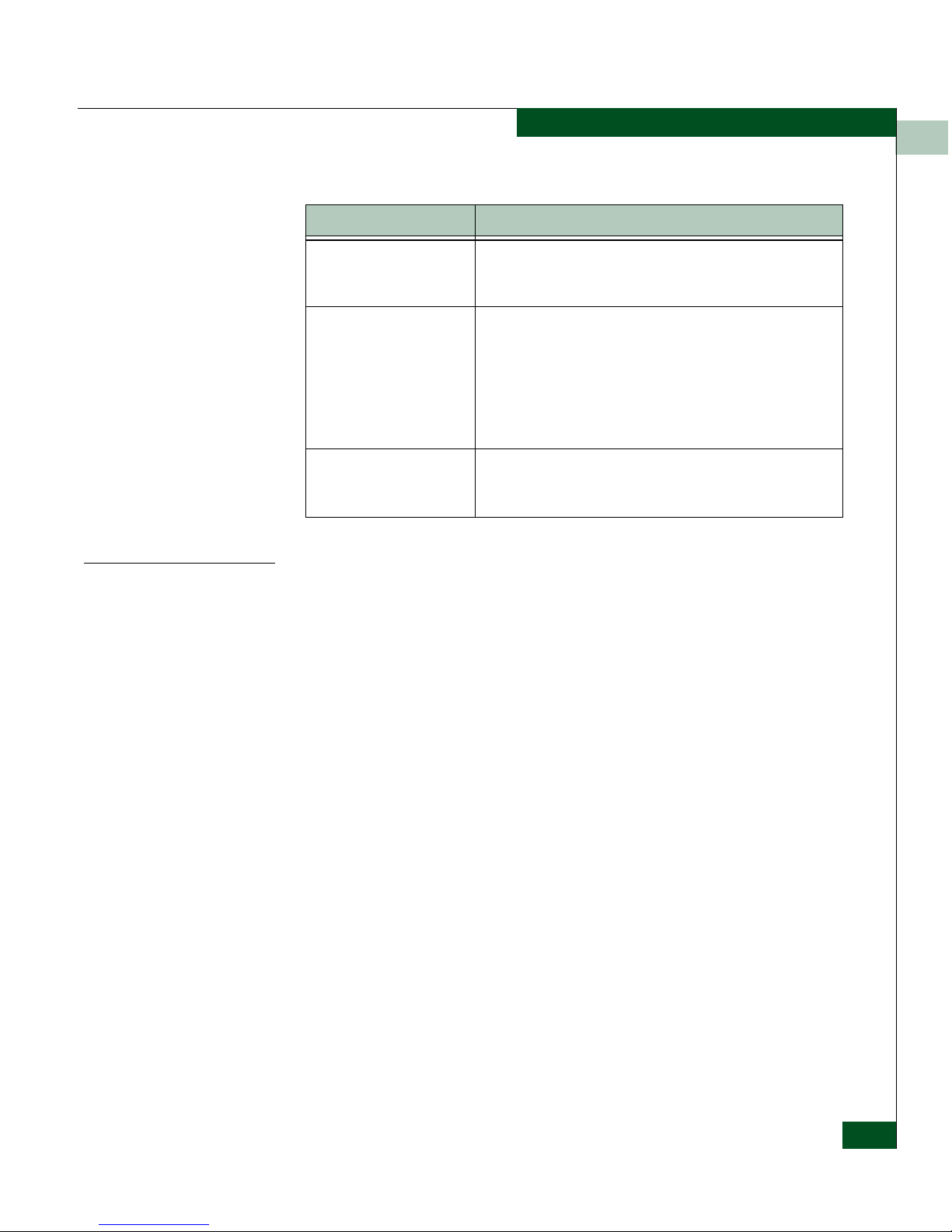
Table 1-1 Eclipse 2640 SAN Router Features
Feature Description
Intelligent Ports The SAN Router supports two types of ports - standard ports
and intelligent ports. A standard port can be configured for
Fibre Channel traffic. An intelligent port can be configured for
Ethernet port Internet Small Computer Systems Interface
(iSCSI) or Internet Fibre Channel Protocol (iFCP).
iFCP standards track
protocols
The SAN Router supports the IETF standard for the iFCP,
which provides connectivity and networking for existing Fibre
Channel devices over a TCP/IP network.
iSCSI A TCP port can be configured for iFCP or iSCSI.
R_Port Support for E_Port, or standard port, through the SAN Router
R_Port, allows you to share devices between SANs while
maintaining each SAN’s independence.
FastWrite The Fast-Write software feature available on intelligent ports
improves the performance of write operations between Fibre
Channel initiators and targets in a Wide Area Network (WAN).
The improved speed depends on the WAN Round Trip Time
(RTT), available buffer space on the target, number of
concurrent I/Os supported by the application, and application
I/O size.
Router Zoning Using SANvergence Manager network management software
or the CLI, you can create zones across networks.
You can use zone sets for periodic reallocation of network
resources. For example, you can have one set of zones for
daytime data transactions and another set of zones for
nighttime backups.
Page 23
1
Overview
1-5
SAN Router Features
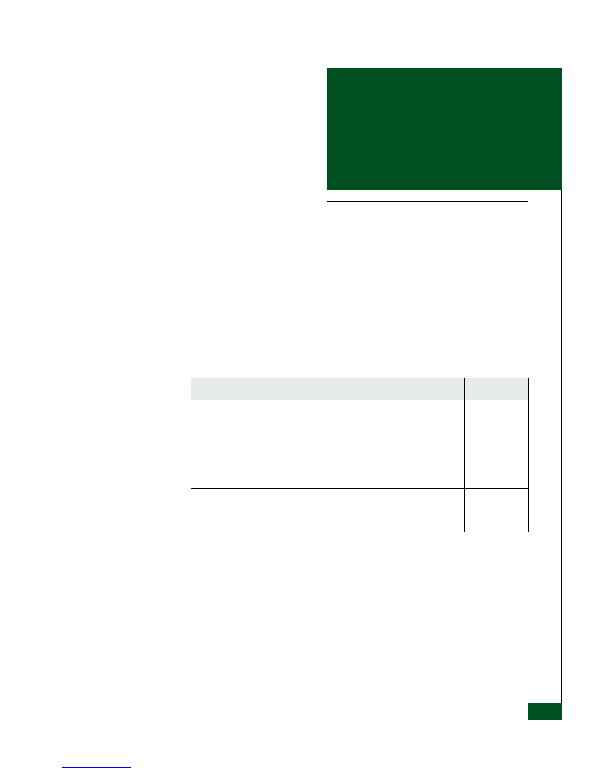
Scalability Metrics
For current scalability metrics on Fibre Channel, zoning, and
iFCP/iSCSI for SAN Router products, such as maximum number of
fabrics per mSAN, maximum imported Fibre Channel devices from a
single fabric, maximum zones in a connected fabric, maximum
number of SAN Routers in an mSAN, and other specifications, refer
to the McDATA Fabric Guidelines (620-000208) on
www.mcdata.com.
Real-time and historical
system logs
The Element Manager and Log Viewer can be used to look at
current system log messages from the connected SAN
Router.
Compression Compression technology available on intelligent ports
identifies repetitive patterns in a data stream and represents
the same information in a more compact and efficient manner.
By compressing the data stream, more data can be sent
across the network, even if slower link speeds are used.
The Eclipse SAN Router supports both hardware and
software compression.
Storage-optimized TCP The storage-optimized TCP features supported by the SAN
Router enhance performance in a dedicated network
deployed in enterprise storage networks.
Table 1-1 Eclipse 2640 SAN Router Features (Continued)
Feature Description
Page 24
1
1-6
Eclipse™ 2640 SAN Router Administration and Configuration Manual
SAN Router Layout
SAN Router Layout
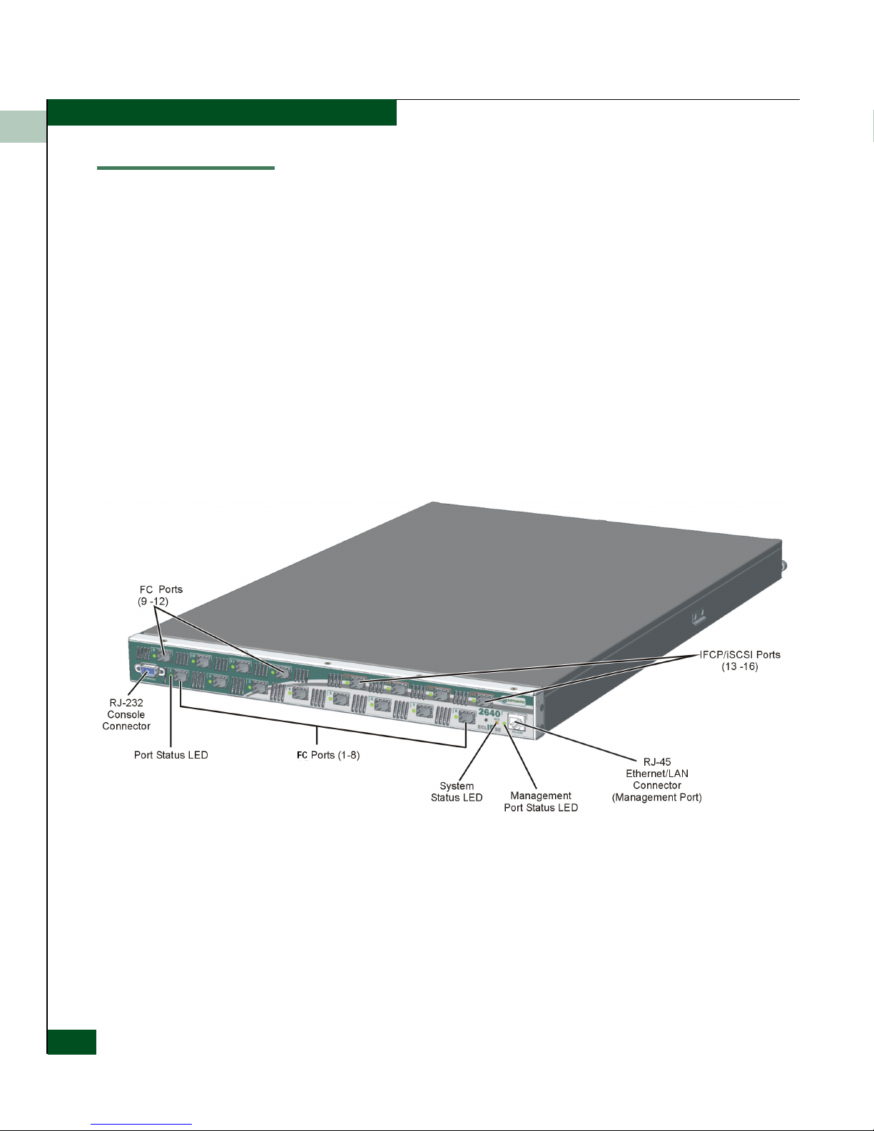
The SAN Router front panel (Figure 1-2 on page 1-6) provides an
Ethernet LAN connector (10/100), small form-factor pluggable (SFP)
connectors port status LEDs, and a green system (SYS) LED. The
panel also provides a 9-pin DSUB maintenance port (CONSOLE) for
connection to a local terminal or remote terminal. The maintenance
port provides an alternate way to configure the SAN Router in
addition to the normal http scenario. Although this port is typically
used by authorized maintenance personnel, operations personnel can
use the port to configure SAN Router network addresses.
Sixteen user-configurable SFP connectors include:
• Ports 1-12, supporting Fibre Channel connections.
• Ports 13-16, supporting iFCP or iSCSI connections.
Figure 1-2 Eclipse 2640 LEDs, Ports, and Connectors
Page 25
Configuring System Basics
2-1
2
Configuring System
Basics
This chapter provides steps for configuring the SAN Router’s basic
functions before performing specific configuration for various
network connections.
Use the following links to move through the chapter.
Section Page
Configuring the SAN Router 2-2
Setting Parameters Through the CLI 2-3
Using the Element Manager 2-5
Tips on using the Element Manager 2-11
Configuring System Operations 2-23
Static Routes 2-36
Page 26

2
2-2
Eclipse™ 2640 SAN Router Administration and Configuration Manual
Configuring the SAN Router
Configuring the SAN Router
You can configure the SAN Router using any of the three options as
follows:
• Command Line Interface (CLI). For this method a VT100 terminal
or PC with terminal emulation software running must be
connected to the RS-232 serial port on the SAN Router.
• SAN Router Element Manager. To use the Element Manger, you
must configure the management port address for the SAN Router
correctly so that you can access the SAN Router through the
Element Manager and SANvergence Manger for configuration
tasks.
• SANvergence Manager. Before configuring the SAN Router with
SANvergence Manager, set up the correct management IP
address and router IP address appropriate for your network.
For all these options, you must first set the management port address
of the SAN Router. This address is set as a permanent one; it is
retained even after the SAN Router is reset to factory results.
The following sections describe the steps required to set the basic
parameters for the SAN Router before you can carry out advanced
configuration.
Setting the Management IP Address
The 10/100 Ethernet port provides for out-of-band IP-based
management, often used for enhanced security. This interface allows
simple network management protocol (SNMP), Telnet, and
web-based management traffic to be separated from storage traffic
through the use of a separate LAN.
The management IP Address is used to receive and respond to
SNMP-based management traffic from management workstations
using the Element Manager and SANvergence Manager. Configure
this IP address for the SAN Router management port through the
Element Manager or CLI.
If the management workstation hosting the Element Manager and/or
SANvergence Manager applications is on a different subnet from that
configured in the Management Port Configuration dialog box, then a
static route should be assigned to explicitly route the management
traffic back to the management workstation. If there are multiple
Page 27

2
Configuring System Basics
2-3
Setting Parameters Through the CLI
management workstations in different networks, then multiple
routes may need to be configured.
Unlike other configuration parameters, when the SAN Router is reset
to factory defaults, the IP address of the management port is retained.
This prevents administrators from locking themselves out of the SAN
Router, requiring console connectivity to reset the management port
IP address.
If the SAN Router is shipped in a cabinet, then the default IP address
will be 10.xx.yy.zz where,
xx is the cabinet number (1, 2, 3, etc.)
yy is the product type identifier (16 for the Eclipse 2640 SAN
Router)
zz is the position in the rack, bottom to top (1, 2, 3, etc.)
NOTE: The management port address must be configured correctly so that
you can access the SAN Router through the Element Manager and
SANvergence manager for further configuration tasks.
You can change the management port address using the CLI or the
SAN Router’s Element Manager.
Setting Parameters Through the CLI
The command line interface (CLI) provides options for out-of-band
management of the SAN Router. You can use the commands
described in the
McDATA E/OSi Command Line Interface (CLI) User
Manual (P/N 620-000207) for these operations.
CLI Procedure To set the management port address using CLI and a serial port
connection, use the following steps.
1. Use a null modem cable to connect a VT100 terminal or any
standard PC running terminal emulation software to the RS-232
serial port on the SAN Router
2. Set the PC terminal emulator settings to the SAN Router default
settings.
Page 28

2
2-4
Eclipse™ 2640 SAN Router Administration and Configuration Manual
Setting Parameters Through the CLI
3. Power up the terminal. Press the Enter key to display the CLI
prompt.
4. Type modify at the Access Mode prompt. This is case-sensitive.
Read is for read-only; modify is for read-write.
5. Type your password at the Password (community string)
prompt. Use private as the password and press Enter.
6. Set the management port IP address with the following
command:
set mgmt portadd <IP address><subnet mask>
where:
• IP address = IP address of the management port
• subnet mask = subnet mask of the management port.
7. Enter a permanent route for a network management station using
the command:
set mgmt permroute <addr><mask><gateway>
where:
• address = IP address of the network management subnet. This
IP address is used to add a static route to the SAN Router’s
route table. This is required by the management station if its
on a different subnet than the 10/100 interface.
• mask = subnet mask of the network management subnet.
• gateway = IP address of the next hop IP gateway. The gateway
is a directly reachable IP router to which management traffic
should be forwarded.
8. To save the configuration, at the command prompt enter:
save
Parameter Setting
Bits per second 9600
Data bits 8
Parity bits None
Stop bits 1
Flow Control None
Page 29
2
Configuring System Basics
2-5
Using the Element Manager
9. Reset the system using the following command:
reset system
The management IP address is now set and ready for normal
operation.
10. If you require a terminal connection to the 10/100 port for
out-of-band management, connect the standard RJ45 Cat 5
Ethernet cable from the LAN to the management port.
11. Ping the IP address that you entered for the SAN Router to verify
network connectivity using the network management host.
If there is no ping response, contact your network administrator
to set up connectivity between the network management station
and the SAN Router.
Using the Element Manager
The Element Manager is a web-based Java applet used to configure,
monitor, and troubleshoot individual SAN Routers. The software is
embedded in every SAN Router, so it does not need to be installed as
a separate program on the management workstation for your mSAN.
Before you begin using the Element Manager, make sure that your
workstation meets the requirements described in this section, that
your browser is set up, and that you review the provided tips.
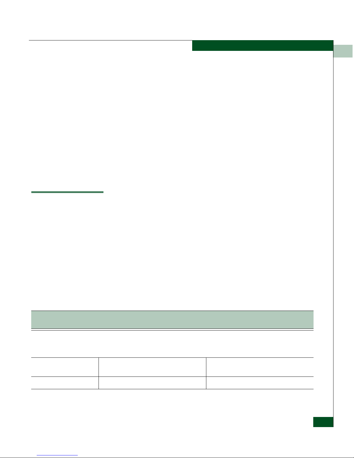
Workstation
Requirements
Workstation requirements for the Element Manager are listed in the
following table:
Table 2-1 Element Manager Workstation Requirements
IBM Compatible Intel Pentium Class PC, 400
MHz or above with mouse, 32-bit
Sun Ultra 5 or better; 300 MHz or above, with
mouse
Operating system
Windows 2003a Server Enterprise Edition
Windows 2000 with SP4
Windows XP with SP2
Solaris 9.0 and Solaris 10.0. Refer to
www.sun.com
Java Runtime Environment
JRE 1.5 and higher (provided with
SANvergence Manager)
JRE 1.4 and later (not provided with
SANvergence Manager)
Management Platform None required None required
Page 30
2
2-6
Eclipse™ 2640 SAN Router Administration and Configuration Manual
Using the Element Manager
Element Manager Overview
The Element Manager software configuration and monitoring
functions are described in Chapters 2 through 8 of this manual.
Web Browser
Internet Explorer 6.0 or higher or Netscape 6.22
or higher
Mozilla 1.4
RAM 128 MB Minimum, 256 MB recommended 128 MB Minimum, 256 MB recommended
Monitor
SVGA (64K color) minimum, 1024 x 768
resolution
SVGA (64K color) minimum, 1024 x 768
resolution
Network Connection TCP/IP Connection TCP/IP Connection
Available Disk Space
50 MB for JRE v1.5
6MB for SANvergence Manager
50 MB for JRE v1.5
6MB for SANvergence Manager
a.DirectX 9.0b or later must be installed on the management workstation if additional software programs, such as EFCM or
PC Anywhere, are coresident with SANvergence Manager.
Table 2-1 Element Manager Workstation Requirements(Continued)
IBM Compatible Intel Pentium Class PC, 400
MHz or above with mouse, 32-bit
Sun Ultra 5 or better; 300 MHz or above, with
mouse
Table 2-2 Element Manager Software Functions
Function Configuration Options
Monitoring (Device View of
SAN Router)
Device View LEDs and icons, system information icons
Color indicators for operational status
Message Log
SAN Router Operations (File
menu)
Save Configuration
Reset System
Firmware Upgrade
System Log
Configuration Backup and Restore
Page 31

2
Configuring System Basics
2-7
Using the Element Manager
Starting the Element Manager
To login to the SAN Router using the Element Manger, follow these
instructions.
System Configuration
(Configuration menu)
Operations
Properties
Inband Address
SNMP Communities/Hosts
SNMP Traps
Date/Time
New Device Zoning
Port Configuration
(Configuration menu)
Management, FC/Ethernet (Fibre Channel, Ethernet and
TCP Ports with iSCSI and/or iFCP)
Advanced FC Port (E_D_TOV and R_A_TOV timeout
values)
Static Routing (Configuration
menu)
Static Routing
iSCSI Device Configuration
(Configuration menu)
Devices
RADIUS Server Configuration
iFCP Configuration
(Configuration menu)
Setup
Remote Connections
Port Redundancy
Reports and Statistics
(Statistics/Info menu)
Ping (iFCP/iSCSI)
GE (Gigabit Ethernet Port statistics)
Fibre Channel (Port Statistics and Device Properties)
Port Traffic Statistics
iFCP port Compression Rate Statistics
MAC Forwarding Table
Internet Protocol (IP) Forwarding
Address Resolution Protocol (ARP) Table
metro storage name server (mSNS) Report
Remote Connection Statistics
Element Manager
Operations (Options menu)
Get Write Permissions
Polling Interval
Table 2-2 Element Manager Software Functions(Continued)
Function Configuration Options
Page 32

2
2-8
Eclipse™ 2640 SAN Router Administration and Configuration Manual
Using the Element Manager
1. In the address field of your browser, enter the management IP
address or DNS hostname of the target SAN Router (for example:
192.168.2.16), in the Address field. Some browsers may require
“http://” before a hostname. The Element Manager login dialog
box appears.
Figure 2-1 Element Manager Login Dialog Box
2. Type the access password for the SAN Router, then click Login.
•The default passwords are public (read access) and
private (read and write, or modify access).
• When the password is verified, the Element Manager Device
View appears.
Page 33

2
Configuring System Basics
2-9
Using the Element Manager
Figure 2-2 Element Manager window
You are now logged in and ready to use Element Manager.
If SANvergence Manager software is installed, click Element Manager
button on the SANvergence screen.
Configuring the Management Port
To configure the out-of-band management port, follow these
instructions:
1. Select Configuration>Port >Management to display the Management
Port Configuration dialog box.
Page 34

2
2-10
Eclipse™ 2640 SAN Router Administration and Configuration Manual
Using the Element Manager
Figure 2-3 Management Port Configuration Dialog Box
2. Enter the IP address and subnet mask address for the
management port.
3. Click Edit Gateway to add the IP address of the gateway router to
the static route table if any of your management stations are on a
different subnet than the one you are specifying for the
management port.
4. Click OK or Apply.
5. Choose Save Configuration to Flash from the File tab to
permanently save the new routing information.
Page 35

2
Configuring System Basics
2-11
Tips on using the Element Manager
Tips on using the Element Manager
Getting Help
An HTML-based help system is available with the Element Manager.
You can search for text on a topic that interests you or browse help
topics sequentially. To view help, choose Index from the Help menu.
You can also click the Help button or press F1 in a dialog box to view
help customized for that dialog box.
To view version information about Element Manager, choose About
Element Manager from the Help menu.
Keyboard Shortcuts
The following function keys provide keyboard shortcuts:
Getting Write Permission
You can login to Element Manager with the read-only password.
However, if you attempt to configure the SAN Router from Element
Manager, the following dialog box prompts you to type the modify
(read/write) password.
Figure 2-4 Get Write Permission Dialog box
Table 2-3 Key Board Shortcuts
F1 Help - Displays help for the current window or dialog box.
F5 Refresh Window - Refresh main screen or a configuration dialog box.
Esc Close the current dialog box
Page 36

2
2-12
Eclipse™ 2640 SAN Router Administration and Configuration Manual
Tips on using the Element Manager
CAUTION
Only one user at a time should be allowed to login with read and
write privileges so as not to write over each other’s changes.
Granting Clipboard Access for Copy and Paste
Element Manager is an unsigned JavaTM applet. As such, default
security settings prevent it from using the system clipboard. This
means that you cannot copy and paste text between Element
Manager text fields and other applications. For example, you cannot
copy Element Manager's message log to another application or copy
long file path names from one dialog box to another in another
application.
However, you can grant clipboard access by editing the Java plug-in
policy file. The policy file is named:
<plug-in-installation-directory>/lib/security/java.policy
On Microsoft Windows, the default installation directory is
• C:\Program Files\Javasoft\JRE\1.3.1 (for version 1.3.1)
• C:\Program Files\Java\j2re1.4.1 (for version 1.4.1)
So the full default file name is:
• C:\Program
Files\Javasoft\JRE\1.3.1\lib\security\java.policy. (for
version 1.3.1)
• C:\Program Files\Java\j2re1.4.1\lib\security\java.policy.
(for version 1.4.1)
On Solaris, if the installation directory is (for example):
• /opt/JRE/1.3.1 (for version 1.3.1)
• /opt/JRE/1.4.1 (for version 1.4.1)
So the full file name would be (for example):
• /opt/JRE/1.3.1/lib/security/java.policy.
(for version 1.3.1)
• /opt/JRE/1.4.1/lib/security/java.policy.
(for version 1.4.1)
Page 37

2
Configuring System Basics
2-13
Tips on using the Element Manager
NOTE: Alternatively, for either operating system, you may instead edit
the.java.policy file (note different name, with period in front) in the user's
home directory. For Windows XP, the directory would be C:\Documents and
Settings\<login-name>.
To grant clipboard access, follow these instructions:
1. Add the following lines at the beginning or end of the policy file
to enable clipboard access for ALL Java applets:
grant {permission java.awt.AWTPermission “accessClipboard”;};
CAUTION
The security risks in granting clipboard access to all applets are:
• An applet could read the clipboard contents and send them
to a remote server. If you have recently cut and pasted
sensitive information, this could be a privacy risk.
• A malicious or malfunctioning applet could fill the system
clipboard with very large amounts of data, consuming
available disk space on your system.
2. Add these lines to the policy file to limit clipboard access to
Element Manager only:
grant codeBase “http://<ip-address-or-hostname>/top/*”
{permission java.awt.AWTPermission “accessClipboard”;};
where <ip-address-or-hostname> is the address or DNS name
used in the web browser for the SAN Router. You must repeat the
lines above for each SAN Router in your network.
3. Restart your web browser to read the new policy file.
Using with Third-Party Browser Extensions
In some cases, the Element Manager cannot be started from a web
browser when a third-party browser extension prevents the JRE
plug-in from loading Element Manager.
If Element Manager cannot start, disable third-party extensions.
Internet Explorer 6.0 allows you to enable or disable third-party
extension support.
Page 38

2
2-14
Eclipse™ 2640 SAN Router Administration and Configuration Manual
Tips on using the Element Manager
1. Select Internet Options under the Tools menu in Microsoft®
Internet Explorer.
2. Click the Advanced tab.
3. Under Browsing, disable Enable third-party browser extensions, if
enabled.
4. Restart your computer.
The Windows XP Service Pack 2 provides the ability to individually
enable or disable an extension (now called an add-on) in Internet
Explorer without entirely disabling third-party extension support.
The FireFox 1.0 browser also supports this feature.
Using Configuration Dialog Boxes
Selecting an option displays a dialog box where you can modify
configuration data. Click OKor Apply in each dialog box to save the
changes.
Apply sets the changes to the SAN Router. The changes are stored in
memory only on the SAN Router, not to flash. OK is similar to Apply
but also dismisses the dialog box after setting the configuration
parameters. Pressing F5 will force a refresh of the dialog box. Any
uncommitted changes will be lost.
To permanently save your changes to the runtime configuration, you
must choose Save Configuration from the File tab.
This saves the currently running configuration to flash memory.
Whenever you choose Reset System from the File tab, the
configuration in flash is restored to the SAN Router.
NOTE: If the configuration has not been saved to flash, a red diskette icon
appears in the bottom left corner of the Device View with a message that
changes are not saved to flash (
Figure 2-2 on page 2-9). A green icon indicates
changes have been saved.
Page 39

2
Configuring System Basics
2-15
Configuring IP Addresses
Configuring IP Addresses
SAN Routers use the iFCP and iSCSI protocols, which use IP
addresses for all routing and forwarding of storage traffic. Using the
iFCP/iSCSI protocol, all Fibre Channel addresses are mapped to one
or more IP addresses.
You must configure two IP addresses with SAN Routers: the external
iFCP/iSCSI network and the IP network. When sending storage
traffic to the external network, SAN Routers uses the “external” IP
addresses associated with the TCP ports. When sending storage
traffic to the internal network, the SAN Routers use the inband address
as the source address for the storage traffic.
Figure 2-5 shows external and internal storage networks. Traffic sent
to the “external” network uses TCP ports, while traffic sent to the
“internal” network uses Fibre Channel ports.
Page 40

2
2-16
Eclipse™ 2640 SAN Router Administration and Configuration Manual
Configuring IP Addresses
Figure 2-5 Internal and External IP Addresses
A SAN Router has iFCP/iSCSI ports that are connected to the
external IP network, and one or more ports that are connected to the
internal IP network. Each TCP port connects to each network (both
the internal and external networks) as an independent device. The
TCP port uses the iFCP/iSCSI IP address to talk to the external
network and the internal IP network IP address to talk to the internal
network.
Page 41

2
Configuring System Basics
2-17
Configuring IP Addresses
The Figure 2-5 shows the role and position of each IP address relative
to the internal and external IP networks.
The Router Inband IP Address
The router inband IP address is used for the internal delivery of
storage traffic.
To configure the SAN Router inband address, use
Configuration>System>Inband Address in the Element Manager.
Figure 2-6 Inband Address Configuration Dialog Box
The iFCP/iSCSI Port IP Address
The “external” iFCP/iSCSI port IP address is used to open and
terminate TCP connections that transport storage data over the
external IP network. Storage traffic received at the iFCP/iSCSI port IP
address can be either delivered to a device directly attached to the
SAN Router or to another SAN Router somewhere in the internal
network.
The iFCP/iSCSI port IP address is configured as the IP address in the
iSCSI/iFCP Parameters section of the Port Configuration dialog box
(
Figure 2-7.)
Page 42

2
2-18
Eclipse™ 2640 SAN Router Administration and Configuration Manual
Configuring IP Addresses
Figure 2-7 FC/Ethernet Port Configuration Dialog Box
The Next Hop Gateway IP Address
The iFCP/iSCSI ports interact with the external IP network as if they
were independent IP hosts. Each iFCP/iSCSI port needs a gateway
address of an external router that can forward the storage traffic to
the remote iFCP/iSCSI port. This Next Hop Gateway Address is the
first-hop gateway address. If the IP address of the remote iFCP/iSCSI
port is in a different subnet from the local iFCP/iSCSI port, then you
must configure the Next Hop Gateway Address. If the remote
iFCP/iSCSI port is on the same subnet as the local iFCP/iSCSI port,
then the Next Hop Gateway Address field is not used and does not need
to be configured.
Page 43

2
Configuring System Basics
2-19
Configuring IP Addresses
The Internal IP Address
Storage traffic that is to be transported through the external network
by iFCP or iSCSI must first be delivered to the iFCP/iSCSI port that
will perform the iFCP/iSCSI encapsulation. The internal IP address is
used by the iFCP/iSCSI port to receive this storage traffic from the
internal network. This traffic is then re-addressed and
re-encapsulated into an iFCP/iSCSI connection that traverses the
external network.
Because the internal IP address is local to the SAN Router, it must be
on the same subnet as the router inband IP address. Storage traffic
from devices directly connected to the SAN Router is delivered from
the router inband IP address to the internal IP address through
Ethernet, before it is re-encapsulated into iFCP/iSCSI for transport
through the external network. Similarly, storage traffic received by
the iFCP/iSCSI port from the external network will be
re-encapsulated using the internal IP address as the source address.
This traffic can then be addressed locally to the router inband IP
address.
Figure 2-8 on page 2-20 shows an iFCP/iSCSI port IP address
configuration, including the iFCP/iSCSI IP address, the internal
address.
Page 44

2
2-20
Eclipse™ 2640 SAN Router Administration and Configuration Manual
Configuring IP Addresses
Figure 2-8 FC/Ethernet Port Configuration Dialog Box
Guidelines When Working with Firewalls
The iFCP and iSCSI protocols use TCP for transmission. TCP
provides several benefits such as:
• Retransmission of any packets dropped by the network.
• Guaranteed in-order delivery.
• Fields that are leveraged by firewall devices for added security.
Prior to transmitting data, TCP must first establish a connection
between the TCP sender and the TCP receiver. Only after a
Page 45

2
Configuring System Basics
2-21
Configuring IP Addresses
connection is established are the TCP segments allowed to be
transmitted from the sender to the receiver.
A firewall can be used to block the establishment of TCP for some
applications while permitting other applications to transmit data. To
accomplish this, firewalls frequently use a combination of TCP port
numbers and IP addresses. Port numbers are used to identify the
sending and receiving application. The port number, along with the
source and destination IP addresses, uniquely identifies each
connection. The TCP header contains two
16 bit fields for the source
port number and the destination port number.
When firewalls are used, it is sometimes necessary to program the
firewall with the port numbers used by iFCP or iSCSI; otherwise the
firewall may block the traffic. The following are guidelines for iFCP
and iSCSI TCP ports and firewalls:
Port Numbers Used by SAN Routers
• These iFCP TCP ports must be opened across the network when
working with firewalls:
E/OSi Firmware: 3.X and above
Control Data hex: 9101 decimal: 37121
hex: 9102 decimal: 37122
Data hex: D5C decimal: 3420
• These iSCSI TCP ports must be opened across the network when
working with firewalls:
E/OSi Firmware: All
Control and Data hex: CBC decimal: 3260
Open Ports The following datapath ports must be open if you want to manage
across a firewall using Element Manager:
•HTTP (80)
• SNMP Protocol (161)
• SNMP Traps (162)
• iSCSI and iFCP information (37009)
Page 46

2
2-22
Eclipse™ 2640 SAN Router Administration and Configuration Manual
Configuring IP Addresses
• Ping operation results (37010)
The following datapath ports must be open if you want to manage
across a firewall using SANvergence Manager:
• SNMP Protocol (161)
• SNMP Traps (162)
Page 47

2
Configuring System Basics
2-23
Configuring System Operations
Configuring System Operations
Configuring the system operations of a SAN Router involves the
following steps:
1. Configuring the system properties
2. Setting the system date and time
3. Setting the SAN Routing Cluster ID
4. Configuring SNMP
5. Configuring the system IP Addresses and static routes
6. Configuring System Metro Storage Name Server (mSNS)
7. Configuring new device zone settings
These steps are described in the following sections.
Configuring System Properties
To configure the system properties, follow these instructions:
1. Choose Configuration>System>Properties to display the System
Properties dialog box (
Figure 2-9 on page 2-24).
Page 48

2
2-24
Eclipse™ 2640 SAN Router Administration and Configuration Manual
Configuring System Operations
Figure 2-9 System Properties Dialog Box
2. Login banner lets you customize the banner which gets displayed
in the HTML starting page above the login dialog box. The
banner may be up to 25 lines long with up to 80 characters per
line.
NOTE: The banner is also shown before the CLI and Telnet session login
prompts.
Page 49

2
Configuring System Basics
2-25
Configuring System Operations
Figure 2-10 Login Banner
3. Click OK or Apply.
4. Choose Save Configuration from the File tab to permanently save
your changes to the runtime configuration. This saves the
currently running configuration to flash memory.
Setting the SAN Routing Cluster ID
The R_Port SAN Routing Cluster ID is used by the SAN Router
R_Ports to register a unique virtual node WWN to the connected
fabrics. Third-party management applications use this WWN to
manage the SAN Router. Each SAN Router is its own single-member
cluster. Each SAN Router connected to an mSAN must have a
different cluster ID.
Page 50

2
2-26
Eclipse™ 2640 SAN Router Administration and Configuration Manual
Configuring System Operations
The values set take effect only after the SAN Router R_Ports are
disabled and enabled (re-initialized).
NOTE: Changing the cluster ID changes the registered virtual switch node
WWN. This may require the management applications to re-discover the
SAN Router.
Procedure
To set the cluster ID, follow these instructions:
1. Select Configuration>System>Operations to display the System
Operations dialog box.
Figure 2-11 System Operations Dialog Box
2. Enter a number for the cluster ID, in the range 1-63.
3. If you want to enable remote access via Telnet, select the option.
4. Click OK or Apply.
5. Choose Save Configuration from the File tab to permanently save
your changes to the runtime configuration. This saves the
currently running configuration to flash memory.
Page 51

2
Configuring System Basics
2-27
Configuring System Operations
Configuring System Date and Time
To configure the system date and time from the SAN Router’s clock
and configure Simple Network Time Protocol (SNTP), follow these
instructions:
1. Select Configuration>System>Date/Time to display the Date/Time
dialog box.
The Date/Time dialog box displays the current date and time from
the SAN Router’s clock as shown in
Figure 2-12.
Figure 2-12 Date/Time Dialog Box
2. Select the SNTP operating mode for the SAN Router’s internal
clock.
• SNTP Disabled - Select this mode to allow the SAN Router to
keep time using its own internal clock. With this selected, you
can set the time manually under the Current Time section,
using GMT or local time.
• SNTP Client - Select this mode to allow the SAN Router clock
to resynchronize with an external SNTP server each minute.
The SNTP server may be another SAN Router, corporate
server, or even an internet sever if internet access is available.
SNTP Server Address - Enter the IP address of the external
sever.
Page 52

2
2-28
Eclipse™ 2640 SAN Router Administration and Configuration Manual
Configuring System Operations
SAN Router Time Zone - Select a time zone from the drop-down
list.
Daylight Savings Time - Select On or Off from the drop-down
list if daylight savings time pertains to your time zone. The
SAN Router does not automatically change this setting when
daylight savings time begins or ends. You must update this
setting manually.
• SNTP Server - Select this mode to set the SAN Router as an
SNTP server. In this mode, the SAN Router keeps time with its
internal clock and provides this time to SNTP clients. Set the
SAN Router’s date and time manually using the drop-down
lists in the Current Time section.
SAN Router Time Zone - Select a time zone from the drop-down
list. Specifying the SNTP server’s time zone allows SNTP
clients to adjust the time to their local time zone as needed.
Daylight Savings Time - Select On or Off from the drop-down
list if daylight savings time pertains to your time zone. The
SAN Router does not automatically change this setting when
daylight savings time begins or ends. You must update this
setting manually.
3. Specify the correct date and time if you have selected SNTP
Disabled or SNTP Server.
4. Click OK to apply.
5. Choose Save Configuration to Flash from the File tab to
permanently save your changes to the runtime configuration.
This saves the currently running configuration to flash memory.
Configuring the Router Inband and Gateway Address
NOTE: In Element Manager, the default gateway is represented as a “default
route” in the routing table by specifying a destination address and a mask of
“0.0.0.0”. That is, all traffic not matching a more specific entry in the routing
table will be sent to the “next hop” listed in the default route. The default
route and the default gateway address are the same thing.
Page 53

2
Configuring System Basics
2-29
Configuring System Operations
Configuring the Router Inband Address
To configure the SAN Router’s internal “router inband” address
through the Element Manager, follow these instructions:
1. Select Configuration>System>Inband Address to display the Inband
Address Configuration dialog box (
Figure 2-13).
Figure 2-13 Inband Address Configuration Dialog Box
2. Type the new IP address.
3. Type the new subnet mask address. The subnet mask is the
number of bits that defines the network address in a given IP
address.
NOTE: The SAN Router “inband” address is different from the
management port IP address and must be on a different subnet. Having
them in the same subnet may cause the SAN Router to become isolated
from the backbone network.
4. The default gateway address is shown for convenience. The
gateway address is the IP address of a directly reachable SAN
Router to which routed traffic should be forwarded. To change
the default gateway, click the Edit Gateway button to display the
Static Route Configuration dialog. For more information, refer to
Static Routes on page 2-36.
5. Click OK or Apply. The new inband address takes effect after you
reset the SAN Router. New default gateway addresses take effect
immediately.
6. Choose Save Configuration to Flash from the File tab to
permanently save your changes to the runtime configuration.
Page 54

2
2-30
Eclipse™ 2640 SAN Router Administration and Configuration Manual
Configuring System Operations
Configuring SNMP
To configure the SNMP communities and hosts, follow these
instructions:
1. Select Configuration>System>SNMP Communities/Hosts to display
the SNMP Communities/Hosts dialog box (
Figure 2-14 on
page 2-30).
Figure 2-14 SNMP Communities/Hosts Dialog Box
2. Type the read-only password and read-modify password
(community strings) for the SAN Router.
3. Optionally, enter a list of IP addresses from which the SAN
Router is authorized to accept SNMP requests.
• If you leave the list empty, SNMP requests are accepted from
any management station.
• If you make at least one entry in the table, SNMP requests are
accepted only from addresses included in the table.
4. Click OK or Apply.
Page 55

2
Configuring System Basics
2-31
Configuring System Operations
5. Choose Save Configuration from the File tab to permanently save
your changes to the runtime configuration. This saves the
currently running configuration to flash memory.
Configuring System SNMP Traps
The SAN Router sends SNMP traps to notify the management station
of certain events. Traps can be triggered by one or more events.
Trap Types The following tables describe SAN Router events that trigger specific
SNMP traps. The SAN Router sends SNMPv1 format traps to inform
management stations of certain events. Each trap sent by the SAN
Router is assigned one of 3 severity levels: Info, Warning, or Critical.
The SAN Router may be configured to filter generated traps by
severity.
.
.
Table 2-4 Generic SNMP MIB-II traps, from RFC 1213
Tra p Name Description Severity
0 Cold Start The SAN Router is powered on, or rebooted. Critical
2 Link Down An Fibre Channel port has lost an active link signal. This can also be caused
by manually disabling an active port.
Critical
3 Link Up An Fibre Channel port acquires an active link signal. The port must have
been previously enabled to acquire an active link signal.
Info
4 Authentication Authentication failure from receiving SNMP command with incorrect
community string.
Warning
Table 2-5 RMON Traps, from RFC 1757, Enterprise 1.3.6.1.2.1.16
Tra p Name Description Severity
1 Rising Threshold When the current sampled value is greater than or equal to this threshold,
and the value at the last sampling interval was less than this threshold, a
single event will be generated.
Info
2 Falling Threshold When the current sampled value is less than or equal to this threshold, and
the value at the last sampling interval was greater than this threshold, a
single event will be generated.
Info
Page 56

2
2-32
Eclipse™ 2640 SAN Router Administration and Configuration Manual
Configuring System Operations
.
.
Table 2-6 Fibre Alliance traps, enterprise 1.3.6.1.3.94
Tra p Name Description Severity
1 Conn Unit Status
Change
Sent when the status of a power supply or fan changes. Info
6 Po r t Status
Change
A port status has changed. Sent when a port is enabled or disabled, or the
link goes up or down.
Info
(if port up)
Critical if
port
disabled or
down.
Table 2-7 McDATA Eclipse traps, enterprise 1.3.6.1.4.1.4369.3
Tra p Name Description Severity
1 SNS Server The SAN Router has become the primary SNS server. Info
3 Firmware Loaded A new firmware image has completed a TFTP download to flash memory. Info
5 Voltage Too High A power supply voltage has exceeded its rated maximum value. Critical
6 Voltage Too Low A power supply voltage has dropped below its minimum allowed value. Critical
7 Temperature The SAN Router's internal temperature has exceeded the rated maximum. Critical
8 Fa n Failed One or more fans have failed in the SAN Router. Warning
9 Power Supply
Changed State
A power supply has changed state from up to down or down to up. Warning
14 iFCP Backup Not
Ready Warning
Sent when a primary iFCP port cannot be backed up by its configured
backup port. The backup port may be unreachable or not responding, or the
backup port may be unable to act as backup due to its configuration. This
trap may be sent after the SAN Router is reset, when the configuration is
changed, or when an existing backup port becomes unreachable. This trap
repeats when the backup connection is tried again unsuccessfully. There is
no interruption of storage traffic, but the primary iFCP port is no longer
protected from failure. The text message in the variable binding list includes
the IP address of the primary iFCP port that cannot be backed up, and the IP
address of the port configured to be the backup. The cause of the failure
(such as timeout, rejected, or incorrect configuration) is not provided. There
is no trap sent when the backup relationship is established successfully or
re-established successfully.
Warning
Page 57

2
Configuring System Basics
2-33
Configuring System Operations
Configuring Trap Recipients
To configure the SNMP trap recipients, follow these instructions.
1. Select Configuration>System>SNMP Tra p s to display the SNMP
Tr a ps dialog box (
Figure 2-15 on page 2-34).
15 iFCP Backup
Activated
Sent when a backup iFCP port begins to activate its backup connections.
This may be caused by the primary port becoming unreachable or the
primary port informing the backup port that the primary link has gone down.
The backup port will attempt to establish all remote connections learned
from the primary por t. If there are any learned connections, this trap will be
followed by traps, such as trap number 15 and 16, to indicate the success or
failure of each remote connection. The text message in the variable binding
list of this trap includes the IP address of the primary port that has failed and
the IP address of the backup port that is reporting the primary port’s failure.
This trap is not generated in release 4.5.
Critical
16 iFCP Link Up Sent when an iFCP port successfully establishes an iFCP connection to a
remote mSAN. If the port makes multiple remote connections, one trap is
sent for each connection. The connection may be a normal connection or a
backup connection. The text message in the variable binding list includes
the IP address of the iFCP port making the connection and the IP address of
the remote end of the connection.
Info
17 iFCP Link Down Sent when an existing remote connection is lost or terminated normally or
when a connection attempt fails. If multiple connections are lost or
terminated or multiple concurrent connection attempts fail, one trap is sent
for each connection. This trap repeats when connection retries fail. The text
message in the variable binding list includes the IP address of the local iFCP
port making the connection and the IP address of the remote end of the
connection. This trap does not specify the reason for the connection being
down (such as timeout on existing connection, user configuration change, or
remote end rejects connection).
Critical
18 R_Port Change An R_Port's configuration has been changed by the user. Info
19 FC Zone Change An R_Port has applied zoning changes to fabric. Warning
20 R_Port Down An R_Port could not connect to its attached fabric. Critical
21 R_Port Fabric
Change
The fabric attached to an R_Port has been rebuilt. This may occur if an Fibre
Channel switch or R_Port is added or removed from the fabric.
Warning
Table 2-7 McDATA Eclipse traps, enterprise 1.3.6.1.4.1.4369.3 (Continued)
Tra p Name Description Severity
Page 58

2
2-34
Eclipse™ 2640 SAN Router Administration and Configuration Manual
Configuring System Operations
Figure 2-15 SNMP Traps Dialog Box
2. Configure up to eight (8) trap receivers, each with a severity filter.
Use the severity level drop down list to specify the traps with
specific severity levels that should be sent to each address.
Figure 2-16 SNMP Traps Filter Pull Down Menu
3. Click OK or Apply.
4. Choose Save Configuration from the File tab to permanently save
your changes to the runtime configuration. This saves the
currently running configuration to flash memory.
Page 59

2
Configuring System Basics
2-35
Configuring System Operations
Configuring mSNS
The SAN Router’s metro storage name server (mSNS) stores the
inventory of hosts and storage devices in the mSAN as well as zoning
information, to specify which hosts can use which storage devices.
SAN Router discovers the Inventory information automatically. You
can view inventory information for locally attached devices by
selecting Storage Name Server from the Statistics/Info tab. For more
information, refer to
Viewing Stati stics on page 6-14.
Configuring New Device Zoning
By default, all new devices attached to the SAN Router, including
router-attached devices (RADs), are unzoned. They are not part of
any zone and cannot talk to any other device. Initially, they are not
even part of the default zone (zone 1). You must explicitly assign new
devices to zones.
To change the default zone behavior:
1. Select Configuration>System>New Device Zoning to display the
New Device Zoning dialog box (
Figure 2-17 on page 2-35).
Figure 2-17 New Device Zoning Dialog Box
2. Click Not a member of any zone to reinstate the factory default.
All new devices will be unzoned, isolated devices that do not
have connectivity with any other zoned or unzoned devices.
Some Fibre Channel HBAs do not interact well when placed in a
common zone, due to vendor unique practices.
Page 60

2
2-36
Eclipse™ 2640 SAN Router Administration and Configuration Manual
Static Routes
3. Click Place in a default router zone (zone 1) to place all new devices
in the default zone (zone 1) where they can communicate with
each other.
4. Click OK.
5. Choose Save Configuration from the File tab to permanently save
your changes to the runtime configuration. This saves the
currently running configuration to flash memory.
Static Routes
Static routes are used to route non-storage payload traffic, such as
management traffic or RADIUS. A SAN Router contains several
different IP subnets:
• The iFCP/iSCSI ports on a unique subnet, or subnets.
• The management port on a unique subnet (the management
subnet can be the same subnet as an iFCP/iSCSI port, but this is
not recommended).
• The internal IP network on a unique subnet.
NOTE: Changes to the permanent route are not active until after the next
SAN Router restart, but changes to other static routes take effect
immediately.
Refer to Figure 2-18.
Figure 2-18 Static Route
Page 61

2
Configuring System Basics
2-37
Static Routes
If the SAN Router is responding to an IP packet that originated from,
for example, the SNMP management station on 10.1.4.2, then it needs
to be told to route the response over the management port to the SAN
Router 10.1.3.1. Static routes are used for this purpose. An entry is
made in the static route table telling the SAN Router to route all
traffic destined to 10.1.4.1 (the IP mask is included to define a range
of addresses) to the next hop SAN Router, 10.1.3.1.
The SAN Router supports three types of static route entries: a
standard entry, a default gateway entry, and a permanent route
entry. All of these entries are stored in flash memory and restored
after the system is reset.
The permanent route is intended for management traffic and is listed
separately on the bottom of the Static Routing Configuration dialog box
(
Figure 2-19 on page 2-38). A permanent route differs from a
standard static route because it cannot be deleted and remains
present even when the system is reset to the factory defaults. Use this
route for traffic to your primary network management station to
ensure management connectivity even when the system is reset to the
factory defaults.
A default route is a static route with a mask of 0.0.0.0 (meaning all
traffic). The default route is used if no other route matches the
destination address. The default route is also called the “default
gateway.”
Traffic that matches more than one route entry will be routed using
the entry with the longest (most specific) subnet mask. Therefore, the
default route will only be used to route traffic that is not otherwise
defined in the static route table.
To manually enter routes, follow these instructions:
1. Select Configuration>Static Routing to display the Static Routing
Configuration dialog box.
Page 62

2
2-38
Eclipse™ 2640 SAN Router Administration and Configuration Manual
Static Routes
Figure 2-19 Static Routing Configuration Dialog Box
NOTE: Use the lower portion of this dialog box to create a permanent
static route to the subnet where your management workstation(s) reside.
For more information, refer to Configuring the Management Port on
page 2-9.
• Destination IP is the IP address of the destination subnetwork.
• Destination IP Mask is the subnet mask of the destination
subnetwork.
• Next Hop is the directly-reachable IP address to which the
traffic should be forwarded.
• Enable Route is a field you can set to Enabled or Disabled. The
default is Enabled. This allows you to create a route, disable it
and enable it when needed.
• Edit Status (along with row color) defines the configuration
state. In a table with multiple entries, a row may say edited,
added or deleted. When you add a new static route, the entry
Page 63

2
Configuring System Basics
2-39
Static Routes
status is Added Not Applied and the row is green. If you select
an entry to be removed, the entry status is Removed Not Applied
and the row is red.
Important Notes for Static Routes
If the SAN Router is to be managed from a single external subnet,
follow the directions under
Static Routes.
There are two ways to manage an SAN Router if different
management stations reside in different subnets.
1. Define static routes for each management subnet as described in
Static Routes.
2. Add a default route by clicking on the Default Gateway in the
Static Routing Configuration dialog box to add the route as the
Static route next hop.
Adding a Route 1. Click Add to display the Static Routing Parameters dialog box.
Figure 2-20 Add Static Route Dialog Box
2. Click Ye s if you wish to enable the route.
3. Type values for the remaining parameters on the dialog box (refer
to
Table 2-8.:
Page 64

2
2-40
Eclipse™ 2640 SAN Router Administration and Configuration Manual
Static Routes
4. Set the Default Gateway or Default Route by entering a destination
and mask of 0.0.0.0.
5. Click Apply or OK.
6. Choose Save Configuration to Flash from the File tab to
permanently save your changes to the runtime configuration.
This saves the currently running configuration to flash memory.
Editing a Route 1. Select an entry in the table.
2. Click Edit.
• A non-default route may only be enabled or disabled. To
change any other field, remove the old route and add a new
one.
• The default route cannot be disabled, but the next hop (default
gateway) may be changed at any time.
•Click the Default Gateway button as a shortcut method to add
or edit the default route.
3. Click Apply or OK.
Removing a Route 1. Select an entry in the table.
2. Click Remove.
3. Click Apply or OK.
Table 2-8 Static Routing Parameters
Item Meaning
Static Route Destination Defines the destination subnetwork of the traffic to be routed by
the static route entry.
Static Route Mask Coupled with the Static Route Destination, the Static Route Mask
defines the destination subnetwork of the traffic to be routed by
the static route entry.
Static Route Next Hop The directly-reachable IP address where the traffic routed by the
entry should be forwarded.
Page 65

Configuring RADs and mSAN Connections
3-1
3
Configuring RADs and
mSAN Connections
This chapter provides steps for configuring the SAN Router and its
Fibre Channel ports for attaching directly to Fibre Channel devices,
such as servers and storage.
Use the following links to move through the chapter.
Section Page
Introduction 3-2
Configuring the FC Ports for Router-Attached Devices 3-4
Configuring R_Ports for mSANs 3-6
Configuring Advanced FC Port Parameters 3-10
Example Configuration and Procedures 3-11
R_port Compatibility 3-14
Page 66

3
3-2
Eclipse™ 2640 SAN Router Administration and Configuration Manual
Introduction
Introduction
You can configure the SAN Router ports for connecting to Fibre
Channel devices directly attached to the SAN Router. These devices,
such as servers and storage devices, are called router-attached
devices (RADs). You can also configure the R_Port to attach to fabrics
that are interconnected by one or more SAN Routers.
R_Port is a fabric extension port used to establish inter-switch links
(ISLs) between a SAN Router and Fibre Channel switches. R_Port
allows you to interconnect, zone and manage existing fabrics with
mSANs. Implementation of R_Port is FC-SW-2 compliant and can
interoperate with other FC-SW-2 compliant fabrics. The Eclipse 2640
R_Port implementation also works with Brocade's pre-FC-SW-2
E_Port implementation.
When a SAN Router is connected to a fabric (Fibre Channel switches)
through R_Ports, the SAN Router and Fibre Channel switches
exchange standard Fibre Channel information, compliant with the
standard FC-SW protocol. Additional device information is
exchanged when other configuration steps are complete, as specified
in the SANvergence Manager User Manual.
mSANs
An mSAN is a collection of one or more fabrics interconnected by a
SAN router, where all the fabrics are within a data center or in
different data centers that are within the metro area. An mSAN is
characterized by low latency, high quality and high bandwidth ISLs
such as those found within the data center or within the metro area
using technologies such as dark fiber, xWDM, MAN services, etc.
Eclipse 2640 SAN routing done within an mSAN is referred to as
mSAN Routing or SAN Routing within the data center. An mSAN
may be referred to as a local mSAN within the context of its own
mSAN, while all the other mSANs that it is communicating with are
referred to as remote mSANs.
Port Configuration Tips
• To directly attach a SAN Router to an Fibre Channel device, such
as a Fibre Channel server or storage, configure the ports 1-12 as
Fibre Channel (FC) ports. For details, refer to the next section,
Configuring the FC Ports for Router-Attached Devices on page 3-4.
Page 67

3
Configuring RADs and mSAN Connections
3-3
Introduction
• To directly attach a SAN Router to an Fibre Channel switch,
configure the ports 1-12 as a R_Ports. For details, refer to
Configuring R_Ports for mSANs on page 3-6.
• Configuring and Managing Zones in R_Port Connected
Networks - SANvergence Manager Version 4.7 or higher is
required to manage zones for R_Port connected networks. For
detailed information on R_Port zone management, refer to the
SANvergence Manager User Manual.
Page 68

3
3-4
Eclipse™ 2640 SAN Router Administration and Configuration Manual
Configuring the FC Ports for Router-Attached Devices
Configuring the FC Ports for Router-Attached Devices
This section describes how to configure the Fibre Channel ports on
the SAN Router as R_Ports for attaching directly to an Fibre Channel
device. To configure R_Ports for attaching to an Fibre Channel switch
(mSAN), refer to
Configuring R_Ports for mSANs on page 3-6.
1. Select Configuration>Port>FC/Ethernet to display the FC/Ethernet
Port Configuration dialog box (
Figure 3-1 on page 3-4).
Figure 3-1 FC/Ethernet Port Configuration Dialog Box
2. Select an Fibre Channel port (1-12) from the Port number list.
Page 69

3
Configuring RADs and mSAN Connections
3-5
Configuring the FC Ports for Router-Attached Devices
3. Type a label for this port in the Port Name field. This label is
displayed in the port tooltip, statistics, and other dialog boxes.
4. Port Speed: Click the Port Speed list and select either 1 Gigabit, 2
Gigabit, or Auto.
For the SAN Router, default port speed is Auto. With this setting,
the SAN Router automatically detects the speed supported by the
connection and sets it appropriately. You can manually configure
the port to 1 Gb/sec or 2 Gb/sec.
5. Select Enable Port to enable the selected port.
6. In the Fibre Channel Port Parameters, select one of the following
types to register RADs.
• FC Auto - Ports that automatically sense whether the type of
connection is F_Port or FL_Port.
• F_Port - A port to which non-loop N_Ports are attached.
• FL_Port - A port to which one or more NL_Ports in an
arbitrated loop are attached.
• L_Port - Private loop or Filer mode. In this mode, the port will
come up in loop mode without requesting devices to do
FLOGI; in other words, the connecting device is forced to be a
private device. Most NAS filers need the port to be configured
in this mode.
For Fibre Channel ports, the port WWN is displayed in a
read-only field.
Page 70

3
3-6
Eclipse™ 2640 SAN Router Administration and Configuration Manual
Configuring R_Ports for mSANs
Configuring R_Ports for mSANs
The following procedure describes how to configure an Fibre
Channel port as an R_Port to attach Fibre Channel devices and
mSANs.
1. Perform steps 1 through 7 under Configuring the FC Ports for
Router-Attached Devices on page 3-4.
2. In the FC/Ethernet Port Configuration dialog box, select R_Port in
the FC Port Parameters section with the Port type.
The configured R_Port parameters appear in the dialog box.
Page 71

3
Configuring RADs and mSAN Connections
3-7
Configuring R_Ports for mSANs
Figure 3-2 FC/Ethernet Port Configuration Dialog Box
Table 3-1 on page 3-8 describes the current R_Port parameters that
may appear.
Page 72

3
3-8
Eclipse™ 2640 SAN Router Administration and Configuration Manual
Configuring R_Ports for mSANs
Table 3-1 R_Port Parameters
Parameter Description
Role The values are Fabric Manager or Non-principal. When a new Fibre
Channel switch is connected and introduced to an existing fabric
through use of the R_Port, an election process is initiated to determine
which switch in the new fabric shall be the principal switch. To avoid
duplicates, the principal switch is responsible for assigning and
coordinating allocation of Domain IDs to every other switch in the
fabric. The SAN Router will never become the principal switch.
If switch needs to be rebooted, the role displays as “Available after
reset.”
Preferred domain IDThe Preferred Domain ID is the default domain ID for an R_Port on the
SAN Router in question. An Eclipse 2640 SAN Router can have 12
R_Ports, each with its own unique Domain ID. The connected Fibre
Channel switches would considers each R_Port as an individual Fibre
Channel switch. The fabric may assign a different ID if necessary.
This ID is a one-byte hexadecimal field used as part of the Fibre
Channel Port ID address, which is maintained by the mSNS in the
mSAN. The allowed range depends on the Interconnection Mode
setting described below.
• For Brocade mode: 1 to 239. 126 and 127 are reserved.
• For Open Fabric1.0 mode: 1 to 29. 30 and 31 are reserved.
• For McDATA Fabric 1.0 mode: 11 to 29. 30 and 31 are reserved.
Use SANvergence Manager or the CLI to set this parameter. To avoid
potential problems with certain fabric topologies, the following domain
ids are not allowed:
Current domain IDYou cannot set this parameter. The current domain ID is the value that
the domain ID is currently set to. The Current Domain ID is 0 for
R_Ports that are not active.
Status You cannot set this parameter. It indicates the status of this R_Port. For
more detailed information on the Status parameter, refer to the R_Port
status table in the SANvergence Manager User Manual.
Fabric Manager
Port WWN
You can not set this parameter. This is the world wide name (WWN) of
the Fabric Manager R_Port for the FC SAN.
Interconnect
mode
Use SANvergence Manager to set this parameter. This is the
interconnection mode to this fabric. Modes are:
• Open Fabric 1.0 - Use for fabrics that are connected to third- party
FC switches that support the FC-SW E_Port implementation.
• McDATA Fabric 1.0 - Use for fabrics that are connected to McDATA
switches that support this McDATA native mode.
• Brocade - Use for fabrics that are connected to Brocade switches.
Page 73

3
Configuring RADs and mSAN Connections
3-9
Configuring R_Ports for mSANs
3. To configure the R_Port using different parameters that are
displayed, use SANvergence Manager. Refer to instructions for
configuring R_Port parameters in Chapter 4 of the McDATA
SANvergence Manager User Manual (620-000189).
4. Note that the FC port timeouts, E_D_TOV and R_A_TOV, must
be configured the same on the SAN Router and all Fibre Channel
switches in an attached fabric. To configure these parameters,
refer to
Configuring Advanced FC Port Parameters on page 3-10.
Zone policy Use SANvergence Manager to set this parameter. Options are Append
Router Zones, and No Router Synch (Synchronization):
Append Router Zones - The SAN Router Storage zone set is
appended to the active zone set on the fabric connected by the R_Port.
No Zone Synch - The zone set information between the mSAN and
the fabric connected by the R_Port is not synchronized.
The SAN Router Zone Policy specifies how zone information is
synchronized between the mSAN and the connected fabrics. For more
detailed information on the set SAN Router Zone Policy parameter,
refer to the SANvergence Manager User Guide.
Fabric Name used to create the FC ID (name) used by the SAN Router to
identify the attached fabric.
Insistent Domain IDThis is a boolean (enable/disable) flag to make the preferred domain ID
a required domain ID. If enabled, the value set for the preferred domain
ID becomes the domain ID when the fabric initializes. If the preferred
domain ID is not accepted by the principal switch in the fabric, the
R_Port will be isolated from the fabric.
Table 3-1 R_Port Parameters (Continued)
Parameter Description
Page 74

3
3-10
Eclipse™ 2640 SAN Router Administration and Configuration Manual
Configuring Advanced FC Port Parameters
Configuring Advanced FC Port Parameters
To configure FC port timeouts, follow these instructions:
1. Select Configuration>Port >Advanced FC Port to display the
Advanced FC Port Configuration dialog box.
Figure 3-3 Advanced FC Port Configuration Dialog Box
2. Select the Port number from the list. The current timeout values
are displayed and may not be changed.
• EDTOV - (Error detection timeout value in seconds). This is a
short timeout used to detect an error condition. The value
EDTOV represents a reasonable timeout value for detection of
a response to a timed event.
• RATOV (Resource allocation timeout value in seconds) - A
long timeout value used to determine when to reinstate a
recovery qualifier. The value RATOV represents EDTOV plus
twice the maximum time that a frame may be delayed within a
fabric and still be delivered.
3. Enter the timeout values you wish to be in effect after the next
system reset in the After next reset column.
Page 75

3
Configuring RADs and mSAN Connections
3-11
Example Configuration and Procedures
Example Configuration and Procedures
This section provides a specific example of procedures to configure a
SAN Router for a RAD, as well as an mSAN consisting of an Fibre
Channel switch and attached storage (
Figure 3-4).
Figure 3-4 Connecting to Fabric and FC Device
The configuration in Figure 3-4 on page 3-11 shows both the SAN
Router and the Fibre Channel switch with no pre-configured zones.
Port 4 of a SAN Router will be connected to a port on the Fibre
Channel switch. The FC server is connected to port 3. The FC WWN
of the HBA in the server is 0x10000000C9232E47. There is a JBOD
connected to the FC switch, which has six disks with WWNs as
shown in the figure. This section describes this sample configuration
using R_Ports.
To create the port configuration, follow these instructions:
1. Make sure the SAN Router is not connected to the FC switch.
2. Start the Element Manager for that SAN Router to configure an
R_Port.
Page 76

3
3-12
Eclipse™ 2640 SAN Router Administration and Configuration Manual
Example Configuration and Procedures
3. Follow steps under Configuring the FC Ports for Router-Attached
Devices on page 3-4 to configure port 3 for connecting to the FC
server. Make sure to select FC-Auto under FC Port Parameters on
the FC/Ethernet Port Configuration dialog box.
4. Follow steps under Configuring R_Ports for mSANs on page 3-6 to
configure port 4 as an R_Port.
5. Make sure that the fabric timeout values E_D_TOV, R_A_TOV for
both the mSAN and the fabric match. Refer to
Configuring
Advanced FC Port Parameters on page 3-10.
6. Save the new configuration by choosing File>Save Configuration.
Reset the SAN Router by choosing File>Reset System for the new
configuration to take effect, if required.
7. Now that the R_Port configuration is complete, physically
connect the ports on the SAN Router and the FC switch together.
8. On the SANvergence Manager main screen, select the mSAN in the
mSANs pane where the SAN Router is located, then select mSAN
Configuration to display the mSAN Configuration screen. Confirm
that all the devices from the fabric are shown under the R_Port
(port 4 that has the icon).
9. Select Actions>Fabric Configuration to display the Fabric
Configuration window.
10. After you have established the physical connection, use the
Selective Import option in the SANvergence Manager to import
the devices from the FC switch into the mSNS. Importing the
devices make the SAN Router and the FC switch register the new
device information with their respective Name Servers. The FC
switch registers with its simple name server (SNS) and the SAN
Router with its metro storage name server (mSNS).
11. Select the R_Ports tab to set the Preferred Domain ID to a unique
Domain ID on the fabric.
If you are not using the default, set the interconnect mode for the
FC switch.
12. Create a zone using SANvergence Manager.
13. Add the server attached to port 3 and the devices attached to port
4 to the newly created zone, while making sure that you are
adding individual devices and not fabric ports into the zone.
14. Click Commit and save the configuration to flash when prompted.
Page 77

3
Configuring RADs and mSAN Connections
3-13
Example Configuration and Procedures
As soon as the zone configuration is activated from SANvergence
Manager (by clicking Commit), the zone set is also registered with the
fabric zone server. Since you created the router zone set during the
R_Port configuration process, the new zone set is also activated in the
fabric.
Configuration Notes for All R_Ports on the Same Fabric
• E_D_TOV and R_A_TOV values must be the same.
• Domain IDs must be different. However, IDs can be the same on
two different fabrics.
• World Wide Node Name (WWNN)-based zoning is not
supported. In order to maintain interoperability between the
McDATA fabric and third party fabrics, ensure that “soft” zoning
on the fabric side is done using World Wide Port Names of
devices instead of World Wide Node Names of devices.
Guidelines for Using Zone Policy
The following are guidelines for using zone policy:
• Append Router Zones is the default setting when an R_Port is first
configured.
• No Zone Synchronization may be preferred if the native FC SAN
management utility is used for configuring zoning. This is
especially true if all the devices reside in the fabric (the devices
are not directly attached to SAN Router ports).
Any device zoned by SANvergence Manager is visible to all
fabrics, whereas unzoned devices are invisible. With No Zone
Synchronization in effect, it is only necessary to create one zone
that contains all the devices that need to be shared between
fabrics. There is no need to duplicate the actual zoning
configuration present in each of the fabrics.
• In mixed mode environments, with some devices attached to
SAN Router ports and others residing on fabrics, it is
recommended that Append Router Zones be used instead of the No
Zone Synch option as the configuration process is more involved.
• FC SAN management utilities from some FC switch vendors may
not be capable of displaying devices outside the local fabric. In
this case, use Append Router Zones zoning policy.
Page 78

3
3-14
Eclipse™ 2640 SAN Router Administration and Configuration Manual
R_port Compatibility
R_port Compatibility
The following R_Port compatibility table shows support for attaching
Fibre Channel switches to the Eclipse 2640 SAN Router. The Fibre
Channel switches must be operating in either McDATA Fabric 1.0 or
Open Fabric 1.0 interoperating mode.
Table Notes
Since the SAN Router supports multiple fabrics in a seamless fashion,
we recommend that the user not inter-mix switch vendors in the
same fabric.
Table 3-2 R_Port Compatibility
Connection Modes
FC Switch Firmware Release
McDATA
Fabric 1.0
Open
Fabric 1.0 Brocade
McDATA Sphereon
3016, 3032, 3216,
3232, 4500 and
Intrepid 6064 and 6140
E/OS 5.2, 5.3, 6.1, 6.2,
7.0, 8.0
X X
McDATA Sphereon
4300
E/OS 6.1, 6.2, 7.0 X X
McDATA Intrepid
10,000
E/OSn 6.0 X X
Brocade 3900 4.1.2a,b X X
Brocade 3200 / 3800 3.1.1a,b,c X X
Brocade 2400 2.6.1a,b,c X X
Brocade 12000 4.1.2b X X
Qlogic SANBox2 1.3.64.00, 3.0, 4.0, 4.1 X
IBM Blade server IBM Qlogic 2.0.0.19 X
Cisco 9509 1.3.5 X
Page 79

Configuring iSAN Connections
4-1
4
Configuring iSAN
Connections
This chapter provides detailed steps for configuring the SAN Router
ports for iFCP and setting up iFCP connections. Use the following
links to move through the chapter.
Section Page
Introduction 4-2
Configuring TCP Ports for iFCP 4-4
Configuring iFCP Connections 4-14
Configuring a Backup iFCP Connection 4-22
Example Configurations and Procedures 4-24
Page 80

4
4-2
Eclipse™ 2640 SAN Router Administration and Configuration Manual
Introduction
Introduction
An iSAN (internetworked storage area network) is a collection of one
or more fabrics interconnected using one or more SAN Routers,
where at least one fabric is in a distant location outside the metro
area. An iSAN is characterized by high latency and low bandwidth
inter-switch links (T1, T3, OC3, etc.) such as those found in wide area
networks. An iSAN has at least two SAN Routers that are
interconnected using iFCP connections. An iSAN is also a collection
of two or more mSANs. SAN routing done within an iSAN is referred
to as iSAN Routing or SAN Routing over distance.
Figure 4-1, iSAN Configuration Example illustrates two mSANs
interconnected through an iFCP link to create an iSAN. iFCP
interswitch links (ISLs) can be used to overcome scalability limits of a
single mSAN. iFCP is also recommended for connection across a
WAN, as this provides higher performance when using features such
as FastWrite and compression.
Page 81

4
Configuring iSAN Connections
4-3
Introduction
Figure 4-1 iSAN Configuration Example
Chapter 3 provides instructions for configuring the SAN Router to
create an mSAN by attaching fabrics to the SAN Router R_Ports.
Chapter 4 provides steps for interconnecting mSANs with remote
mSANs over a WAN. Connections to the network are made through
those SAN Router’s TCP ports available for configuring FC Protocol
(iFCP) connections.
Page 82

4
4-4
Eclipse™ 2640 SAN Router Administration and Configuration Manual
Configuring TCP Ports for iFCP
Configuring TCP Ports for iFCP
This section describes how to configure the TCP ports (port numbers
13-16 on the Eclipse 2640 SAN Router) for iFCP connections.
This involves the following procedures:
• Setting the general port parameters
• Setting advanced TCP parameters
• Setting the iFCP parameters
Configuring the General Port Parameters
1. From the Element Manager, select Configuration> Port>
FC/Ethernet
Page 83

4
Configuring iSAN Connections
4-5
Configuring TCP Ports for iFCP
Figure 4-2 FC/Ethernet Port Configuration Dialog Box
2. Select a port. The screen is refreshed to show the operational
state.
3. Type a label for this port in the Port Name field.
4. Set the port speed under the Port Speed list, if needed and select
the Enable Port checkbox.
5. Select or clear the Autonegotiations check box as required. This
option determines whether the port advertises its autonegotiation
properties to a receiving device per the autonegotiation specified
by IEEE standard 802.3.
Page 84

4
4-6
Eclipse™ 2640 SAN Router Administration and Configuration Manual
Configuring TCP Ports for iFCP
6. Select the Flash LED option to blink the port LED. You can use
this option to locate the physical port in a rack of SAN Routers.
Setting the Advanced TCP Parameters
The SAN Router provides options to optimize the TCP port behavior
through a set of advanced parameters. Use the following procedure
to configure the advanced TCP parameters.
1. Click the Advanced button. The Advanced TCP Configuration dialog
box appears (
Figure 4-3 on page 4-6).
Figure 4-3 Advanced TCP Configuration
In the TCP section:
•Select Auto-reset port on severe errors especially when the port is
a part of a mission-critical configuration.
Page 85

4
Configuring iSAN Connections
4-7
Configuring TCP Ports for iFCP
Manual Reset: You may not want the auto-reset option to be on
when you are troubleshooting unrecoverable errors. In this
case, you can do a manual reset by clicking Reset Port in the
FC/Ethernet Port Configuration dialog box.
2. Set the MTU size.
The MTU (maximum transmission unit) size can be used to
prevent accidental fragmentation when the path (discovered)
MTU value, as returned by paths from/to this port, is incorrect.
This can occur with some security/encryption appliances on the
network, where the MTU size may not be correctly reported. The
following options are available:
• Auto - Use the discovered MTU size. This is the default setting.
• Manual - Forces the system to use the configured value for
MTU size and DOES NOT do auto-discovery. The range is
from 512 to 4096, the default size is 1500.
• Min (Auto, Manual) - Does auto -discovery and uses the
minimum of the discovered and configured values.
Storage-optimized TCP Parameters:
Storage-optimized TCP is a set of enhancements made to the TCP
behavior to ensure high throughput in a dedicated network in
enterprise environments typically used for storage traffic. These
enhancements are built on the inherent reliability of TCP by
optimizing the traffic control features in a dedicated network.
Following are the TCP feature enhancements that make up the
storage-optimized TCP:
• Reorder resistance in case of out-of-order packet delivery.
• Quick start with higher initial value of congestion window.
• Smaller reduction in congestion window on slow start and fast
retransmit.
• Disabling congestion avoidance phase in fast retransmit and
fast recovery.
• Reduced slow start timeout.
You can implement these enhancements by selecting the checkboxes
provided in the
Advanced TCP Configuration on page 4-6.
Page 86

4
4-8
Eclipse™ 2640 SAN Router Administration and Configuration Manual
Configuring TCP Ports for iFCP
1. Select Smaller CWND Reduction in Fast Recovery to improve the
performance of the SAN Router when packet losses occur due to
reordering or noise rather than congestion. When enabled, the
SAN Router responds more slowly to congestion events because
the send congestion window (CWND) is reduced to 7/8 of its
previous value as compared to 1/2 in standard TCP.
NOTE: Do not select this option when other traffic sources sharing the same
TCP link are bursty or intermittent.
2. Select Quick Start to improve the initial performance and error
recovery performance on dedicated links with a lot of traffic.
Enabling this increases the initial value for the congestion
window at the beginning of TCP slow starts, and increase the
congestion window size more rapidly.
Standard TCP uses Slow Start to protect a network and the other
traffic on it from a sudden burst that can cause congestion
difficulties.
3. Select Reduced Slow Start Timeout to reduce the minimum Slow
Start timeout from 500 msec to 150 msec. This improves
responsiveness to congestion events that trigger Slow Start.
4. Disable Standard Congestion Avoidance to disable the slow growth
mode of the SAN Router's congestion window that occurs in the
standard TCP stack when a congestion event is detected.
A congestion event occurs when there is either a transmission
timeout (slowstart timeout) or sufficient duplicate
acknowledgements trigger the fast recovery algorithm. The
growth of the congestion window in congestion avoidance is
normally at the rate of 1/cwnd bytes per ACK received.
5. Select Reorder Resistance for reliable links that reorder packets.
Selecting this option will reduce unnecessary packet
retransmission caused by packets being reordered in the TCP
path.
Selecting Reorder Resistance increases the number of duplicate
ACKs required to trigger a Fast Retransmit or Fast Recovery. Use
the next step to specify the number of ACKs.
NOTE: Enabling reorder resistance could slightly delay recovery from
dropped packets in short data messages.
Page 87

4
Configuring iSAN Connections
4-9
Configuring TCP Ports for iFCP
6. Specify the number of ACKs that trigger Fast Retransmit or Fast
Recovery using the Threshold field. Valid values are between 8 to
128, with a default of 8. Larger values reduce retransmissions by
causing the SAN Router to wait longer for retransmitted packets
to arrive. This may delay the detection of dropped packets.
Setting the iFCP Parameters
1. To set the port as iFCP, select iFCP from the iFCP/iSCSI
parameters field.
2. Specify the IP address. This is the iFCP/iSCSI IP address that will
be used for this port after the next port reset or system reset.
NOTE: This IP address must be in a subnet different from the SAN
Router’s inband subnet.
3. Specify the Subnet mask. This is the subnet mask to use for this
port after the next port reset or system reset.
4. Specify the Next Hop Gateway Address.
This is the gateway address to use for this port after the next
system reset. TCP ports act as end nodes (hosts) attached to the
WAN, and therefore may have a different gateway than the
default gateway used by UDP ports connecting to the local
mSAN.
5. Specify the internal IP address.
The internal IP address is used with the SAN Router's inband IP
address for internal control. The TCP port acts as a proxy between
the SAN Router's internal network and the external WAN
network.
NOTE: The internal address must be in the same subnet as the SAN
Router's inband IP address.
6. Select the iFCP tab from the Advanced TCP Configuration dialog
box (refer to
Figure 4-4) to specify the iFCP parameters:
Page 88

4
4-10
Eclipse™ 2640 SAN Router Administration and Configuration Manual
Configuring TCP Ports for iFCP
Figure 4-4 Advanced TCP Configuration iFCP Parameter
1. Select the compression behavior for the TCP/IP port using the
Compression Level combo box. Compression is an optional
software feature; the Compression Level field is disabled if
compression is not included in your software version.
Compression technology takes advantage of replicated characters
or patterns being sent across a network port to effectively increase
throughput on that port. Only the payload is compressed and not
the TCP/IP header. Packets with a size less than 512 bytes are not
compressed. Compression is especially useful when transmitting
data over a slow link such as a T1 or 10
Mbps Ethernet. The
following options are available for Compression Level:
• None - Data that is going out of the port is not compressed.
This is the default setting.
Page 89

4
Configuring iSAN Connections
4-11
Configuring TCP Ports for iFCP
• HW - All transmitted data is compressed using the hardware
feature in the SAN router. This is the recommended setting if
the remote destination also supports HW compression.
• SW - All transmitted data is compressed, using the SAN
router’s CPU. Use this setting when you need to use as little
bandwidth as possible and the remote destination does not
support hardware compression. Note that effective
throughput with the “SW” setting may be less than the
effective throughput seen with the “SW as needed” setting,
especially at link speeds greater than T3.
• SW as needed - Depending on the available bandwidth,
decision are dynamically made whether or not to compress
transmitted data. With SW As Needed setting on, the port keeps
the egress data rate as close as possible to the port speed of the
port.
2. Specify the compression algorithm by selecting the Compression
Method. Compression is an optional software feature; the
Compression Method field is enabled only if the Compression Level is
SW or SW as needed.
The multiple compression methods allow a trade-off between
compression rate (speed) and compression ratio (amount of
compression). The following options are available for Compression
Method:
• LZO - performs compression on a frame-by-frame basis. This
method is best when there are many active initiator-target
sessions. This is the default setting.
• Fast LZO with History - performs compression two bytes at a
time with eight kB of history. This works best with fewer
active iFCP initiator-target sessions and a fast remote link.
• LZO with History - performs compression one byte at a time
with eight KB of history. LZO w/History gives the next best
compression ratio, but has a compression rate of about 25
MB/s. For link Rates of 100 Mb/s or less use LZO w/History.
This works best with fewer active iFCP initiator-target
sessions and a medium speed remote link (for example, T3).
• Deflate - provides the best compression ratio, but has the
lowest compression rate. For link rates of 10 Mb/s or less use
Deflate (may be called ZLIB). This is best for slow links, such at
T1, with any number of active iFCP initiator-target sessions.
Page 90

4
4-12
Eclipse™ 2640 SAN Router Administration and Configuration Manual
Configuring TCP Ports for iFCP
Select Hardware Compression from the Compression Level
drop-down list. This has the lowest compression ratio, but it
can run at link rate.
3. Select Selective ACKnowledgement (SACK) to acknowledge
non-contiguous sequence numbers. This reduces the amount of
retransmitted data when packets are lost. Enabling this provides
better performance in congested networks (assuming the remote
device also supports SACK).
Setting FastWrite Features
1. Select the FastWrite feature to improve performance for distance
over 200 Km. The FastWrite feature can minimize the data
transfer delay for write operations on long distance links by
responding to Initiator Write commands with TransferReadys. This
fills the WAN pipes and buffers the data at the SAN Router that is
closest to the target. The SAN Router that is buffering the data
then feeds it to the actual target at the rate that the target can
handle. Therefore, FastWrite makes up for the round-trip delays
typical of most WAN links. Note that FastWrite does not spoof
Write Status commands, thus ensuring data integrity.
NOTE: Port reset is not required when changing FastWrite options in the
TCP Advanced Options dialog box
When the FastWrite is enabled, several additional parameters are
available to customize the FastWrite behavior:
• XFER_RDY Limit: The maximum number of XFER_RDY
commands that may be issued early by the SAN Router to
avoid round trip delays. The limit is applied to each Fabric
Channel login session.
• XFER_RDY Windowing: When selected, the configurable
XFER_RDY limit is treated as a moving “window” of
consecutive XFER_RDYs that may be issued by the early
SAN router. If not selected, the XFER_RDY limit is simply
the total number of XFER_RDY commands that can be
simultaneously outstanding for each login session.
• Remote Buffer Management: When selected, the local SAN
Router limits the amount of buffer memory used in the
remote SAN Router by limiting the amount of data
requested by the local SAN Router and sent to remote SAN
Page 91

4
Configuring iSAN Connections
4-13
Configuring TCP Ports for iFCP
Router without a XFER_RDY from the target device.
Specify the maximum amount of buffered data, in
kilobytes, in the text field. The memory limit is a single
pool for all Fabric Channel login sessions.
• Selecting the Transmit Buffer Management option allows the user
to manage the amount of Fabric Channel receive buffers that
an iFCP port has for receiving the Fabric Channel frames
forwarding from Fabric.
In cases where ELSs are issued in the middle of large amount
of data packets and the iFCP/TCP side is connected to a slow
link (e.g. OC3 link), user may experience ELS timeout. ELS
timeout occurs when ELSs have command timeout values
shorter than normal Read / Write commands and when ELSs
are queued behind the large amount of Read/Write data.
Reducing the number of Fabric Channel receive buffers will
cause congestion back into any attached device or fabric to
occur sooner or for lower amounts of outstanding data, which
then minimizes the ELSs timeout condition.
NOTE: Transmit buffer option may cause head of line blocking and
congestion which might lower the performance of the system instead of
helping it.
• Select the Defaults button to reset all options in the iFCP area
to the following:
• Compression Level - Off
• Compression Method - LZO
• Selective ACKnowledgement - enabled
•FastWrite - disabled
• Transmit Buffer Management - disabled
Page 92

4
4-14
Eclipse™ 2640 SAN Router Administration and Configuration Manual
Configuring iFCP Connections
Configuring iFCP Connections
To configure an iFCP connection, configure a TCP port (13-16) as
iFCP, as described in
Configuring TCP Ports for iFCP on page 4-4. A
pair of SAN Routers connects two mSANs. Each mSAN is identified
by a unique mSAN ID and each has its own mSNS. Only configure a
mSAN ID when iFCP is being used. Otherwise, there is only a single
mSAN.
To configure the SAN Router for iFCP connections, select the
following options from the Configuration>iFCP tab:
•Select Setup to configure the mSAN ID for the iFCP function.
•Select Remote Connections to configure connection-specific
parameters. refer to
Configure Remote iFCP Connections on
page 4-15.
Configuring iFCP Setup
To configure the SAN Router for iFCP connection, follow these
instructions:
1. Select Configuration>iFCP>Setup to display the iFCP Setup dialog
box (
Figure 4-5).
Figure 4-5 iFCP Setup Dialog Box
2. Optionally, change the Active on next reset mSAN ID.
• A new mSAN ID takes effect when you reset the system. Thus,
two IDs are shown: the ID currently in effect and the ID that
will be used after you reset the system.
Page 93

4
Configuring iSAN Connections
4-15
Configuring iFCP Connections
• Set the local mSAN ID when the SAN Router is installed. The
default value is zero (0). The local mSAN ID is a number
between 0 and 4,294,967,295 that uniquely identifies the local
mSAN.
NOTE: The SAN Router at each end of the iFCP link (and thus the mSANs at
each end) must have different mSAN IDs.
Configure Remote iFCP Connections
For each SAN Router, you must specify a list of the remote SAN
Routers to which it should export zones.
To configure the remote connections, follow these instructions:
1. Select Configuration>iFCP>Remote Connections to display the
Remote Connections dialog box (
Figure 4-6).
Figure 4-6 Remote Connections Dialog Box
Page 94

4
4-16
Eclipse™ 2640 SAN Router Administration and Configuration Manual
Configuring iFCP Connections
Table 4-1 Read-Only Remote Connections Parameters
Column Description
Connection Indicates whether the connection is primary (manually configured on
this SAN Router) or backup (automatically copied from this SAN
Router or another SAN Router so the local SAN Router can back up
the connection).
From The connection port on the local SAN Router. If the port is not
configured for iFCP, the remote connection will fail.
To The connection destination in the remote SAN. This is the IP address
of a port on a SAN Router in the remote SAN.
Description A short note of up to 32 characters to describe this connection. This
field is not used by the iFCP connection; it is just a convenience for the
storage administrator. Descriptions are only shown for primary
connections. For backup connections, the Description field indicates
which connection this one is backing up.
mSAN ID The numeric ID of the remote mSAN at this connection’s destination.
Every mSAN connected by iFCP through a SAN Router has a unique
ID. The remote mSAN ID displayed here is the ID assigned to the
remote mSAN, not the local mSAN. The remote mSAN ID may be 0 if
the connection is not active.
MTU The actual MTU size used by the connection. The actual MTU may be
different than the discovered MTU if the port MTU is manually
configured.
Window Size The size for all TCP connections on this link. Auto means the window
size is selected for each TCP connection depending on the round-trip
time measurements. Any other user-defined value indicates a constant
window size established in the parameters for this connection.
Status This is the current status of this connection. Select F5 to refresh the
status table. Up indicates the connection is up and working and
connected to the remote address shown in the To column. Down
indicates the connection is enabled but is not operating for several
reasons. Disabled indicates you have disabled the connection using
the Edit button or the Disable shortcut button (this applies only to
primary connections). Idle/Ready indicates a backup connection is
ready to take over if the primary fails but is not currently in use (this
applies only to backup connections).
Alternate Path Shows the source and destination of the alternate link, if any. For
primary connections, this field describes the backup connection. For
backup connections, this field describes the primary connections.
Exported Zones A list of zone IDs exported on this connection.
Page 95

4
Configuring iSAN Connections
4-17
Configuring iFCP Connections
NOTE: Backup connections (identified by Backup in the Connection column)
cannot be selected, even when the backup connection is active. Backup
connections cannot be edited or removed. These connections inherit their
settings from the corresponding primary connection.
CAUTION
When exporting zones across iFCP, make sure the zone members
are device WWNs and not fabric ports, as fabric port zones are not
supported across iFCP.
To configure an iFCP connection going to a remote SAN Router,
follow these instructions:
1. Click Add on the Remote Connections dialog box to display the Add
Remote Connections dialog box (
Figure 4-7).
Page 96

4
4-18
Eclipse™ 2640 SAN Router Administration and Configuration Manual
Configuring iFCP Connections
Figure 4-7 Add Remote Connection Dialog Box
Use this dialog box to add new remote iFCP connections or edit
parameters for existing connections.
You can modify information in this dialog box as described in
Table 4-2.
Page 97

4
Configuring iSAN Connections
4-19
Configuring iFCP Connections
CAUTION
If you make zone changes using SANvergence Manager, do a
refresh (press F5 or click Refresh) to update the list of available
zones.
2. To edit existing remote connection information, select one or
more rows in the table and click Edit. This displays the Edit
Remote Connections dialog box (
Figure 4-8 on page 4-20).
Table 4-2 Remote Connections Parameters
Setting Description
Connection Description Enter up to 32 characters of description to help remember the
purpose of this connection.
Local SAN Router Port Select the port on the local SAN Router from the drop-down
list.
Remote SAN Router IP
Address
IP address of the SAN Router that is providing TCP access to
the remote SAN. Enter the remote SAN Routers WAN port
address.
Connection State Select Enabled from the drop-down list for normal sharing of
devices between SANs. Select Disabled to prevent sharing of
storage devices. While the connection is disabled, the
connection acts as if it were not present in the list at all.
Connection timeout The connection timeout is the maximum time that the remote
SAN Router can remain unreachable before the connection is
closed. The default is 10 seconds.
TCP Window Size The size for TCP connection on this link. Auto indicates the
window size is selected for each TCP connection depending
on the round-trip time measurements. Manual indicates any
other user-defined value entered in the text field next to the
Manual button.
Exported zones This table lists the zones exported over iFCP connections
through the SANvergence Manager.
Page 98

4
4-20
Eclipse™ 2640 SAN Router Administration and Configuration Manual
Configuring iFCP Connections
Figure 4-8 Edit Remote Connection Dialog Box
NOTE: To select a range of connections, select the first, then hold down
the Shift key while selecting the last connection. To select a set of
connections, hold down the Ctrl key while clicking on each connection.
3. To remove iFCP connections, select one or more rows in the table
and click Remove. Removing a remote connection terminates all
data sessions to that SAN Router. All devices in the remote
mSAN are removed from the remote mSNS and are no longer
available to the local mSAN.
4. Enable or disable remote connections, if needed (Refer to
Configure Remote iFCP Connections on page 4-15).
• Select the connections to be enabled or disabled and click the
Enable or Disable button below the list of remote connections.
Page 99

4
Configuring iSAN Connections
4-21
Configuring iFCP Connections
• A connection with a status of Down is enabled but inactive.
The SAN Router periodically attempts to restore a failed
connection. If you wish to initiate a reconnection attempt (for
example, after you’ve corrected the cause of the connection
failure), select the connection and click the Restart button.
5. Press F5 or click the Refresh button to refresh the list of remote
connections, including their status information.
NOTE: Restarting a connection is equivalent to disabling and then
re-enabling the connection.
Page 100

4
4-22
Eclipse™ 2640 SAN Router Administration and Configuration Manual
Configuring a Backup iFCP Connection
Configuring a Backup iFCP Connection
You can configure redundant fail-over for the iFCP connection so that
one iFCP port backs up another iFCP port on the same SAN Router.
Redundant ports must be configured symmetrically; for example,
each port must back up the other. A port can have both primary and
backup connections, such as pair of ports having connections to a
remote SAN, exporting different zones to split the load. If either port
fails, the remaining port takes over the entire load.
To configure a backup for the SAN Router ports, follow these
instructions:
1. Select Configuration>iFCP>Port Redundancy to display the iFCP
Port Redundancy Configuration dialog box (
Figure 4-9).
Figure 4-9 iFCP Port Redundancy Configuration Dialog Box
2. Select the tab for each port you wish to configure.
3. To enable backup operation, select the Enable box. To disable
backup operation, clear this box.
4. Select the port that you want to backup for the port being
configured.
 Loading...