

Page 1

PRO MAC 54
PRO MAC 61
54CC
59CC
Page 2
A.B.C.D.E.
Page 3
Page 4
F.
G.
Page 5

H.
I.
L.
Page 6

PRO MAC 54 PRO MAC 61
18”/45cm
68T
72T
72T
GB
3/8”
20”/50cm
3/8”
20”/50cmSP
3/8”
Due to a constant product improvement programme, the factory reserves the
225735B
225739B
86826B (7/32”)
225736B
225740B
86826B (7/32”)
225735B
225739B
86826B (7/32”)
225736B
225740B
86826B (7/32”)
225737B
225740B
86826B (7/32”)
right to modify technical details mentioned in this manual without prior notice.
Im Sinne des Fortschritts behält sich der Hersteller das Recht vor, technische
DE
Änderungen ohne vorherigen Hinweis durchzuführen.
La Maison se réserve la possibilité de changer des caractéristiques et des don-
FR
nées de ce manuel à n’importe quel moment et sans préavis.
Door konstante produkt ontwikkeling behoud de fabrikant zich het recht voor
NL
om rechnische specificaties zoals vermeld in deze handleiding te veranderen
zonder biervan vooraf bericht te geven.
Produsenten forbeholder seg all rett og mulighet til å forandre tekniske detaljer
NO
i denne manualen uten forhåndsvarsel.
Jatkuvan tuotteen parannusohjelman tähden valmistaja pidättää oikeuden vaih-
FI
taa ilman ennakkovaroitusta tässä ohjekirjasessa mainittuja teknisiä yksityiskohtia.
Tilverkaren reserverar sig rätten att ändra fakta och uppgifter ur handboken
SE
utan förvarning.
Producenten forbeholder sig ret til ændringer, hvad angår karakteristika
DK
og data i nærværende instruktion, når som helst og uden varsel.
La firma productora se reserva la posibilidad de cambiar las características
ES
y datos del presente manual en cualquier momento y sin previo aviso.
A casa productora se reserva a possibilidade de variar características e dados
PT
do presente manual em qualquer momento e sen aviso prévio.
La casa produttrice si riserva la possibilità di variare caratteristiche e dati del
IT
presente manuale in qualunque momento e senza preavviso.
Λγω προγράµµατος συνεχούς βελτίωσης προϊντων, το εργοστάσιο
GR
επιφυλάσσεται του δικαιώµατος να τροποποιεί τις τεχνικές
λεπτοµέρειες που αναφέρονται στο εγχειρίδιο αυτ χωρίς
προηγούµενη ειδοποίηση.
Folyamatos gyártmány felùjítási müsorunk következtében, a gyártó cég fenntart-
HU
ja a jogát ebben a Használati leirt müszaki adatok elözetes értesítés nélküli változtatására.
Page 7

THIS PRODUCT MEETS THE SAFETY STANDARD REQUIREMENT OF THE EUROPEAN
MACHINERY DIRECTIVE
DISPLACEMENT (cm3) ................................................................................................................
BORE AND STROKE (mm)..........................................................................................................
ENGINE OUTPUT (kW)................................................................................................................
ENGINE SPEED AT MAX POWER (min
MAXIMUM SPEED (min
MINIMUM SPEED (min
-1
) ............................................................................................................
-1
) .............................................................................................................
-1
) ....................................................................................
DRY WEIGHT (Kg) (NO BAR AND CHAIN) ..................................................................................
CHAIN PITCH (9,525 mm)...........................................................................................................
CHAIN GAUGE (mm)...................................................................................................................
BAR LENGTHS (cm)....................................................................................................................
No. OF SPROCKET TEETH ........................................................................................................
SPECIFICATIONS
OIL TANK CAPACITY (cm
FUEL TANK CAPACITY (cm
3
) .........................................................................................................
3
)......................................................................................................
SOUND PRESSURE LEVEL (AT THE OPERATOR’S EAR). LpAav (dBA) (EN 27182 - EN 608)...
SOUND POWER LEVEL LwAav (dBA) (ISO 9207 - EN 608)........................................................
VIBRATION LEVEL (ISO 7505 - EN 608) (m/s
2
)............................................................................
UK
54 59
45x34 47x34
2,6 2,82
8.200 8.200
11.000 11.000
2.500 2.500
6,25 6,25
3/8” 3/8”
1,5 1,5
45/50 45/50
77
390 390
590 590
101 101
109 109
9,25 8,02
QUESTO PRODOTTO È CONFORME ALLA DIRETTIVA EUROPEA SULLA SICUREZZA
DELLE MACCHINE
CILINDRATA (cm3)....................................................................................................................
ALESAGGIO x CORSA (mm) ....................................................................................................
POTENZA (kW).........................................................................................................................
REGIME Dl MASSIMA POTENZA (min
REGIME MASSIMO (min
REGIME DI MINIMO (min
-1
) ........................................................................................................
-1
) .......................................................................................................
-1
) ..................................................................................
PESO A SECCO (Kg) (SENZA BARRA E CATENA) ...................................................................
PASSO CATENA (9,525 mm) ...................................................................................................
SPESSORE CATENA (mm).......................................................................................................
LUNGHEZZA BARRA (cm)........................................................................................................
DATI TECNICI
No. DENTI DEL PIGNONE........................................................................................................
CAPACITÀ SERBATOIO OLIO (cm
CAPACITÀ SERBATOIO MISCELA (cm
3
) .........................................................................................
3
) ..................................................................................
PRESSIONE SONORA ALL’ORECCHIO DELL’OPERATORE LpAav (dBA) (EN 27182 - EN 608).
POTENZA SONORA LwAav (dBA) (ISO 9207 - EN 608)............................................................
VIBRAZIONI (ISO 7505 - EN 608) (m/s
2
) ..................................................................................
CE PRODUIT EST CONFORME À LA NORME EUROPÉENNE POUR LA SÉCURITÉ DES
MACHINES
CYLINDRÉE (cm3).....................................................................................................................
ALÈSAGE / COURSE (mm).......................................................................................................
PUISSANCE MOTEUR (kW)......................................................................................................
REGIME MOTEUR PUISSANCE MAX (min
REGIME MAXIMUM (min
REGIME DE RALENTI (min
-1
)........................................................................................................
-1
) ....................................................................................................
-1
).............................................................................
POIDS A VIDE (Kg) (SANS BARRE NI CHAÎNE) ........................................................................
PAS DE LA CHAÎNE (9,525 mm) .............................................................................................
JAUGE (mm).............................................................................................................................
LONGUEUR DE GUIDE (cm).....................................................................................................
NOMBRE DES DENTS DE PIGNONS.......................................................................................
CAPACITÉ DU RÉSERVOIR HUILE (cm
CAPACITÉ DU RÉSERVOIR ESSENCE (cm
3
)..................................................................................
3
)............................................................................
PRESSION SONORE À L’OREILLE DE L’OPERATEUR. LpAav (dBA) (EN 27182 - EN 608)......
NIVEAU DE BRUIT LwAav (dBA) (ISO 9207 - EN 608) ..............................................................
CARACTÉRISTIQUES TECHNIQUES
VIBRATIONS (ISO 7505 - EN 608) (m/s
2
) ..................................................................................
I
54 59
45x34 47x34
2,6 2,82
8.200 8.200
11.000 11.000
2.500 2.500
6,25 6,25
3/8” 3/8”
1,5 1,5
45/50 45/50
77
390 390
590 590
101 101
109 109
9,25 8,02
F
54 59
45x34 47x34
2,6 2,82
8.200 8.200
11.000 11.000
2.500 2.500
6,25 6,25
3/8” 3/8”
1,5 1,5
45/50 45/50
77
390 390
590 590
101 101
109 109
9,25 8,02
Page 8

UK
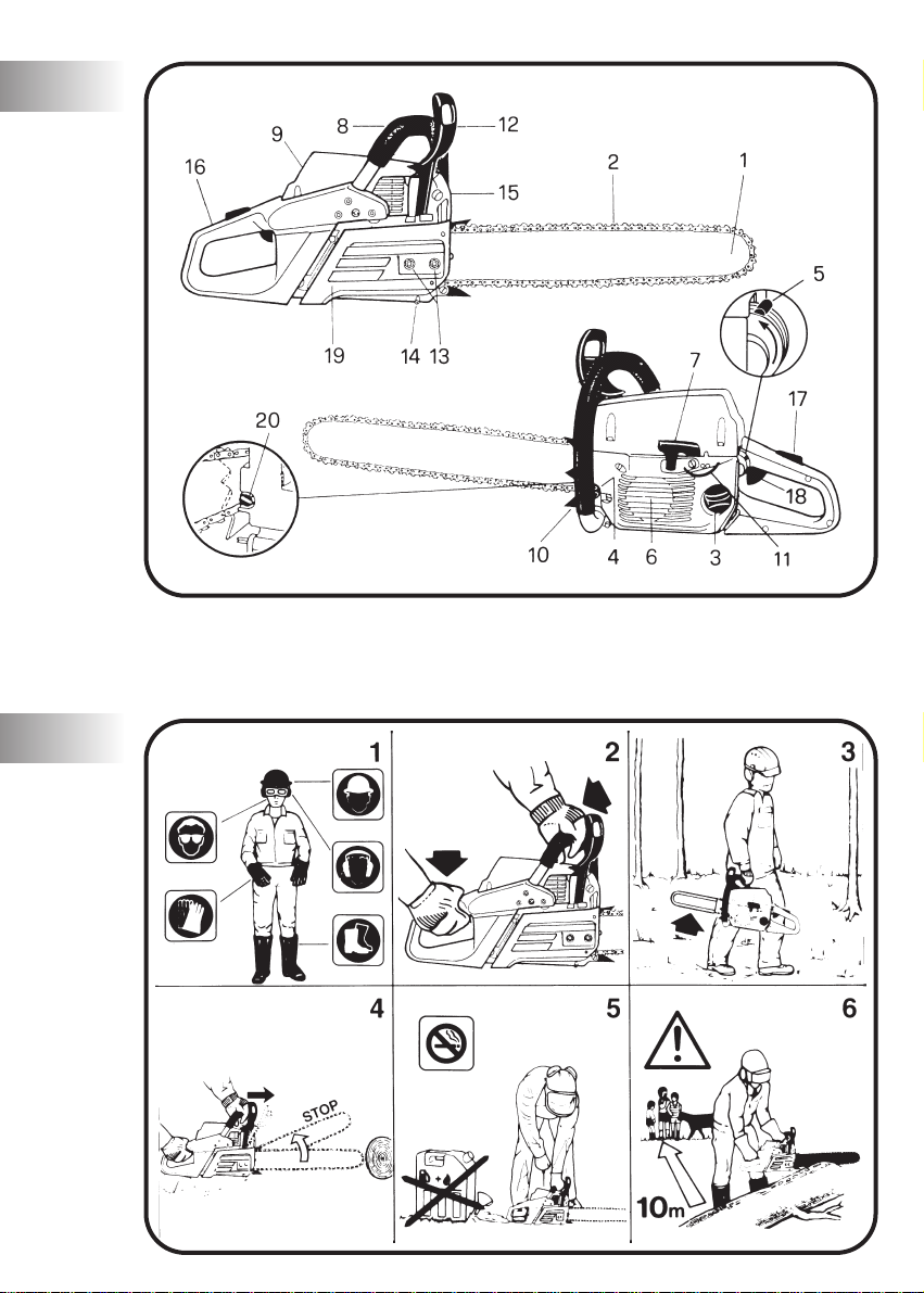
SYMBOL MEANING
Read operator’s manual carefully
Wear safety clothing:
1 Approved safety glasses or face shield
2 Approved safety helmet
3 Approved ear defender
4 Approved gloves
5 Approved safety footwear
Do not smoke while refuelling
or while operating the machine
Warning - Caution
Choke fully opened
(hot start /run)
Choke partially opened
GENERAL DESCRIPTION
1 - BAR
2 - CHAIN
3 - FUEL TANK CAP
4 - OIL TANK CAP
5 - STOP / RUN LEVER
6 - STARTER HOUSING
7 - STARTER HANDLE
8 - FRONT HANDLE
9 - AIR FILTER COVER
10 - SPIKE/SPACER
11 - CARBURETOR ADJUSTMENT SCREWS
12 - SAFETY CHAIN BRAKE
13 - BAR RETAINING NUTS
14 - CHAIN CATCHER
15 - MUFFLER SHIELD
16 - REAR HANDLE
17 - THROTTLE TRIGGER LOCKOUT
18 - THROTTLE TRIGGER
19 - CHAIN BRAKE COVER
20 - CHAIN ADJUSTER SCREW
A
Choke closed
(cold start)
Brake engaged / disengaged
Beware of kickback
Do not cut with the end on the bar,
this may cause kickback
Never use the machine
with only one hand
Always use the machine
with both hands
SAFETY PRECAUTIONS
1 All operators should read this manual carefully before
using this chainsaw; only use this machine for usage
specifically mentioned in this manual.
Wear suitable clothing. This should include snugly-fitting
(safety) clothing, sturdy boots, heavy duty gloves, goggles
or a face screen and ear plugs or ear mufflers. Wear a helmet if there is risk of falling objects or projections from
trees.
2 Always hold the chainsaw firmly with both hands when the
engine is running. Always maintain a firm foothold. Ensure
you are able to stop the engine quickly if necessary.Do not
work up a tree unless you have received suitable training
and have the appropriate equipment (belts, ropes, safety
hooks etc.) for this type of work.
We strongly recommend that all first-time chainsaw users
obtain practical instruction on safe chainsaw usage before
operating the chainsaw.
Do not operate this machine when tired or under the
influence of any substances, drugs or alcohol which can
impair vision, dexterity or judgement.
Prolonged use of chainsaws or other machines exposing
the operator to vibration may produce Whitefinger’s
Disease (Raynaud’s Phenomenon). This may reduce the
hands’ ability to feel and regulate temperature and may
B
1
Page 9

UK
produce general numbness. Continual or regular users
should therefore monitor closely the condition of their
hands or fingers. If any of the symptoms appear, seek
immediate medical advice.
3 Never carry the chainsaw with the engine running.
Whenever carrying a chainsaw, even for short distances,
the chain should be covered by the chain guard (scabbard)
and the bar should point backwards.
When transporting the chainsaw in a vehicle, secure the
saw to prevent fuel spillage.
4 To avoid kick-back, do not attempt to cut with the nose of
the bar. Ensure the engine is running at full throttle before
commencing to cut. To avoid kick-back, do not let the
nose of the bar come into contact with logs, branches, the
ground or any other obstruction. Do not allow any part of
the chain to come into contact with rock, nails or wire
fence
Ensure the chain is kept sharp and correctly tensioned.
Keep the spike or the saw body against the wood when
cutting. Use only genuine accessories and spare parts. We
recommend you have your unit periodically checked and
serviced by an authorised dealer.
Do not use chainsaw above shoulder height.
5 Do not operate the chainsaw near a naked flame or spilled
fuel. Only operate the chainsaw outside and in well ventilated areas.
After re-fuelling, always wipe off any spilled fuel. Move the
chainsaw away from the fuelling point before starting the
engine.
6 Keep by-standers and animals out of the work area; at a
minimum distance of 10 m or twice the timber length. If
necessary, use warning signs to keep on-lookers at a
distance.
Carefully survey the working site to note any hazards, eg.
roads, paths, electricity cables, dangerous trees etc. Do not
use the chainsaw if the device for stopping the chain (safety
chainbrake) does not work correctly. Never place hands on
the chain whilst the engine is running. Ensure someone is
within hearing distance in case of an accident. If this is not
possible, it is recommended that users operating chainsaws in remote areas carry an adequate first-aid kit with
them and ensure someone knows their location. Never
leave the engine running while the tool is unattended.
ONLY USE ORIGINAL SPARE PARTS AND ACCESSORIES.
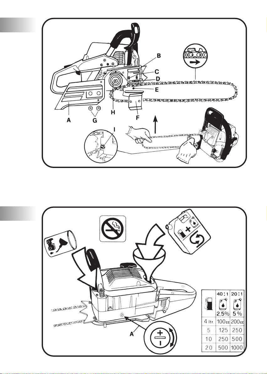
BAR AND CHAIN
INSTALLATION
Ensure engine is always switched off before fitting or adjusting chain. Wear a pair of protective gloves when fitting
or adjusting chain.
A. Clutch guard
B. Inner bar plate
C. Bar mounting bolts
D. Chain tensioning screw
E. Oil hole
F. Outer bar plate
G. Bar retention nuts
H. Sprocket
I. Adjusting screw
C
Remove the clutch guard (A) and the outer bar plate (F).
Check that the oil hole (E) is free from impurities. Fit the chain
over the sprocket (H). Ensure correct direction of cutter tooth.
Put the bar in position over studs (C) slide it towards the
sprocket. Fit the chain into the bar groove and slide the bar
forwards.
Make sure that the tang chain tensioning screw (D) fits into the
hole in the bar (E). Replace the outer bar plate and the clutch
guard. Screw the two bar retention nuts finger tight (G).
Tension the chain by turning the adjusting screw (I) clockwise
while raising the tip of the bar. The tension is sufficient if the
chain is snug on the bar but still moves freely around the bar
when pulled by hand. Tighten the two bar retention nuts securely.
Always use the combination tool to install and tension the
chain.
RUNNING IN A NEW CHAIN
The chain must always be cold when carrying out adjustment.
1 Let the chain run slowly for a few minutes. Check that the
oil pump is delivering oil onto the chain.
2 Stop the engine and adjust the chain tension.
3 Check the tension of a new chain more frequently during
initial usage and adjust as necessary.
4 Repeat adjusting until the chain does not stretch any more.
Never touch the chain while the engine is running.
FUEL MIX
Use only fuel recommended by this manual. This product
is fitted with a 2-stroke engine and therefore requires a
2-stroke petrol and oil mix. Use leaded (4 Star) or unleaded
petrol with a minimum octane rating of 90.
Only use oil from sealed containers. In order to obtain a good
fuel mix, put the oil into the container before the petrol.
The use of sub-standard petrol or oil may reduce performance or reduce the life of certain components.
LEADED PETROL
If using leaded petrol, the correct fuel mix is achieved by
either using 5% (20:1) of a well known brand of 2-stroke
engine oil, or else 2.5% (40:1) of special McCulloch engine
oil.
UNLEADED PETROL
If using unleaded petrol, you must use a totally synthetic 2stroke engine oil or McCulloch branded 2-stroke engine oil. In
either case use 2.5% (40:1) of oil.
IMPORTANT
Always shake this fuel mix vigorously each time you use it.
We recommend to carry out this operation each time you use
the fuel.
Fuel mix properties deteriorate with time, we therefore recommend that you only make the quantity of fuel mix you will
need for each usage. Do not use fuel mix more than a week
old as this could damage the engine.
D
2
Page 10

UK
WARNING
Do not smoke when re-fuelling.
Always open the fuel cap slowly.
Re-fuel in open spaces only, keeping away from naked flames or sparks.
Always store fuel in an approved container.
SAFE STORAGE OF FUEL
Petrol is highly inflammable. Put out all cigarettes, pipes and
cigars before working with petrol. Avoid spilling petrol. Store
fuel in a cool, well ventilated place, in an approved container
specifically designed for the purpose.
Never store engine with fuel in the tank in enclosed, poorly
ventilated areas, where fuel fumes may reach an open flame,
spark or pilot light such as in a furnace, water heater, clothes
dryer etc. Petrol fumes can cause an explosion or a fire. Do
not store large amounts of fuel.
CHAIN LUBRICATION
IMPORTANT
The service life of the bar and chain depends on good lubrication.
Always use chain lubricating oil of medium viscosity. We
recommend special McCulloch chain lubricating oil.
Never use waste oil for this purpose. This results in damage
to the bar, the chain and the oil pump.
Refill the chain oil tank each time the saw is refuelled.
IMPORTANT
The chain oil feed is reduced to a minimum when the regulating bolt is completely closed (turning clockwise)
To prevent possible restarting problems avoid running the
fuel tank dry. This also helps to extend engine life.
NOTE: Saw chain stretches during use particularly when it
is new, and it will occasionally be necessary to adjust and
tighten it. A new chain will require adjustment after about
5 minutes of operation.
• The mechanical oil pump for chain lubrication can be
adjusted.
The feed rate of the chain oil pump can be adjusted by means
of the regulating screw (A) (see details in the illustration). The
oil feed rate is increased by turning the regulation bolt counterclockwise .
IMPORTANT - The chain oil feed is reduced to a minimum
when the regulating bolt is completely closed (turning
clockwise).
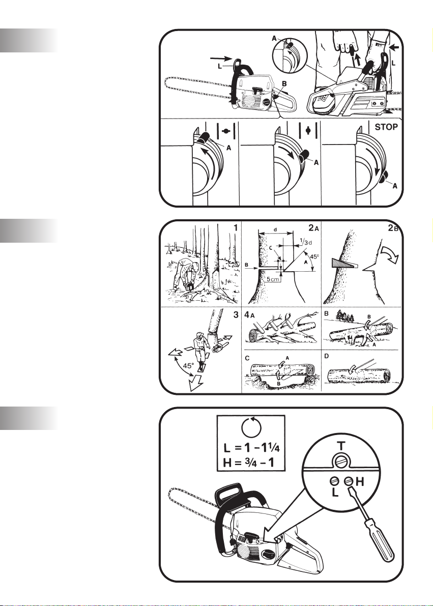
STARTING AND STOPPING
IMPORTANT. Never start or operate unless bar and chain
are properly installed.
Before starting always move the saw away from the fuelling area and place it on firm, flat surface, the guide bar to
the front.
STARTING COLD ENGINE
Check that the chain brake is in the disengaged position
moving the lever (L) backwards (towards the front handle).
Move the stop/run lever (A) up to the cold start position
(choke closed |––•|) When in the cold start position, this lever
also partially opens the throttle.
E
Hold the saw firmly as shown in illustration and pull the starter
rope until the engine fires once.
Once you hear the engine start, or attempt to start, move the
stop/run lever (A) to the intermediate position (choke open
|––•|| ).
ATTENTION: The throttle remains partially open in this posi-
tion and the chain may run. This allows the engine to warm
up.
Pull the starter rope until the engine starts.
Allow engine to warm up for a few seconds, holding the saw
firmly.
Beware of moving chain.
ATTENTION: Squeeze and then release the accelerator trig-
ger (B). This will allow the throttle too close and the chain
should no longer move.
STOP
To stop the engine, move the stop/run lever (A) down, to the
“STOP” position.
IMPORTANT. After lengthy use of the chain saw at full
speed, we recommend to run the engine for a few seconds at
idle speed before stopping it.
STARTING A WARM ENGINE
Leave the start/run lever (A) onto the run position (in the
middle). Pull the starter handle until the engine runs.
IMPORTANT: The automatic accelerator opening system
will only function if the start/run lever (A) is moved up to
the cold start position, and then back down to the run
position (in the middle). Do this if the engine fails to run
after starting.
STARTING A WARM ENGINE AFTER FUELLING
In the fuel tank as run completely dry, procede to start as with
a cold engine.
USAGE
IMPORTANT
Before using a chain saw read the Operator’s Manual and all
safety precautions carefully.
FELLING TREES
– Make sure that there are no bystanders or animals in the
work area.
– Study the direction of the fall of the tree and then plan your
exit path away from the planned direction of fall.
– Don’t fell trees when there is a strong wind.
1 Clear the tree base of interfering limbs and brush. Clean
the work area from stones or other objects which could
damage the chain. If the tree has large protruding roots,
remove them before felling (see illustrations).
2 A) Cut a felling notch (A) of 45°on the side you want the
tree to fall to a depth of about one third of the trunk diameter (d). Then make a felling cut (B) about 5 cm higher
than the felling notch on the opposite side of the tree.
Make sure that the felling cut does not go right through
the trunk. A hinge (C) must always be left to provide
control over the direction of the fall.
F
3
Page 11

UK
B) Use wedges to control the moment and direction of the
fall.
3 When the tree starts to fall, walk away along your preplan-
ned escape path.
CUTTING FALLEN TRUNKS
4 A) Limbing thick branches. For limbing and bucking leave
the lower limbs to support the log off the ground.
B) Supported at one end only. Begin with a bottom cut
made by the upper side of the bar (A); the depth of the
cut should be about one third of the log diameter.
Finnish with a top cut (B) meeting the first one. With this
technique splitting, cracking can be avoided
C) Supported at both ends. Begin with a top cut about
one third of the log diameter. Then finish with a bottom
cut (B) meeting the first one. this technique avoids the
risk of pinching the bar in the log.
D) If the log is supported along its whole length it may be
cut normally from above. Take care not to touch the
ground with the chain.
• When working on a slope always stand on the uphill.
• When cutting prepared timber, use clamps or chocks to
secure work.
• Use extreme caution when cutting small size brush and
saplings which may catch the chain and pull you off balance.
CARBURETTOR
ADJUSTMENT
We suggest carburetor adjustments are made by an authorized servicing dealer.
The carburetor has three adjustment screws:
• L: The needle screw L governs the fuel flow at low speed
and also the acceleration from low to full speed.
To set screw L: close screw L turning it clockwise without
forcing.
Then open screw 1-1/4 full turn (counterclockwise) .
If acceleration is not smooth, open another 1/8 turn to
increase fuel flow .
• H: The needle screw H governs fuel flow at high speed
(throttle valve fully open).
To set hi speed screw H: close screw H turning it clockwise without forcing .
Then open screw 3/4-1 full turn (counterclockwise) .
If the engine speed is too high, open the screw about 1/8
turn (counterclockwise).
• I: The I (IDLE) screw controls the throttle opening to
govern idle speed adjust as necessary.
CAUTION: increased idle speed may cause chain movement.
The carburetor is adjusted for normal operation during production. When considerable changes of altitude require a
supplementary adjustment, contact an authorised service station which offers the latest in tools, parts and technical assistance.
G
ROUTINE MAINTENANCE
Ensure engine is always switched off before any kind of
maintenance operation.
CHAIN: Check tension regularly. A new chain will require
more frequent adjustment. Loosen retention nuts. Tighten
chain (see assembly instructions). Tighten retention nuts and
adjust.
1 BAR
– Clean the bar groove (K) and check the lubrication holes
(L) in the bar to ensure that they are not clogged.
– Grease sprocket periodically. Rotate sprocket and
repeat.
– Rotate bar periodically to maximise bar life.
2 AIR FILTER
– A dust clogged air filter may cause carburetor problems.
This may prevent the engine from reaching its maximum
r.p.m. and cause high fuel consumption.
– Remove cover.
– Wash filter in petrol (do not use fuel which is mixed with
oil).
– The filter can also be cleaned with compressed air.
– Replace filter if damaged or if it does not seal tightly in
the air box.
3 SPARK PLUG
Remove and clean the spark plug every 30 hours. Check
the electrode gap (0,5/0,6 mm. - 0.025 inches).
– Replace spark plug about every 100 working hours or
whenever it is extremely encrusted.
– Heavily encrusted electrodes can result from an incorrect
carburetor setting or from wrong fuel mixture (too much
oil in the fuel mix) or a poor quality of oil in the fuel mix.
Check and correct.
4 OIL FILTER
The oil filter is on the end of the oil suction hose inside the
oil tank.
Remove the chain catcher by twisting it anticlockwise and
remove the oil filter. Use a piece of bent wire or long forceps.
To remove deposits from the oil tank half-fill it with kerosene or petrol and shake thoroughly. Drain off and fill the
tank with fresh saw chain oil.
Never use waste oil.
5 FUEL FILTER
To change fuel filter remove the tank cap and pull out the
filter with a piece of bent wire or long forceps. Replace the
filter as shown in the illustration and reposition it.
It is recommended to replace the fuel filter at least once a
year.
CHAIN BRAKE
– WARNING: Contact your service dealer if anything
appears wrong with your chain brake. Do not disassem-
ble or manipulate the mechanism of the chain brake.
– Clean the brake mechanism periodically (without disas-
sembling it) and control the wear of the band visually.
• PERIODICALLY: It is important to clean the saw thoroughly
particularly around cylinder fins to avoid overheating of the
engine.
• LONG STORAGE: Empty fuel and run engine until dry.
H
4
Page 12

UK
SAFETY CHAIN BRAKE
Your chain saw is fitted with a safety chainbrake designed to stop the chain in milliseconds in case of kickback. Always hold the saw firmly in both hands.
The chain brake does not provide a total protection if the
machine is used without taking the necessary precautions
and maintenances.
The chain brake is intended to engage automatically in case
of kickback.
The chain brake can also be engaged manually by pushing
the chain brake lever forwards.The manual use of the chain
brake is recommended only at idle.
Always test the chain brake before using your saw. Do this
by engaging the brake at idle (see below).
Always release the brake before starting.
Kickback may occur if the end of the bar (see illustrated
angle) touches any solid object.
Never attempt to start a cut with the end of the bar.
Kickback is a violent upward and rearward movement of the
bar and may cause you to lose control of the machine.
Therefore you should avoid starting a cut with this part of the
bar. Always keep a firm grip on the saw with both hands
because, in case of kickback, it is the contact of the left hand
with the brake lever which will help to engage the brake.
CHAIN BRAKE TESTING:
1 The chain brake (A) is disengaged when brake lever is
pulled back and locked(chain can move).
2 The chain brake (A) is engaged when brake lever is in the
position (chain cannot rotate).The chain brake should snap
into both positions.If strong resistance is felt or lever does
not move into either position, DO NOT USE YOUR SAW.
Take it immediately to an authorized servicing dealer.
3 CHAIN CATCHER
This unit is fitted with a chain catcher below the drive
spocket. This is intended to stop the rearward movement of
the chain in case of breakage or if it should come out of the
bar. It should never be removed.
I
CHAIN SHARPENING
1 Chain cutter teeth can be sharpened with a round file,
as follows:
CHAIN FILE
SPR 378 GX 7/32”
The exact chain type is marked on the bottom half of the
drive link which runs inside the bar groove.
Filing can be made easier by also using a file holder.
The chain can remain fitted on the bar during sharpening.
Before commencing, the chain should be tensioned correctly and the chain brake should be activated to prevent
the chain from moving.
2 To obtain a correct sharpening the file must be carefully
held to maintain 3 basic angles:
– “A” Top angle 30° - 35°
– “B” External, side angle 85° - 90°
– “C” Internal, side angle 60°
File in one direction only, from the “inside” of the cutter
tooth towards the “outside”.
Do not allow the file to touch the chain as you bring it
back to re-position it. Each cutter tooth should be filed
with the same number of strokes.
3 The file should be held horizontally to the cutter tooth
being sharpened.
4 Best results to obtain a precise sideways angle can be
obtained by holding the file so that it rises 0,5 mm above
the top face of the cutter tooth.
5 DEPTH GAUGE
Correct depth gauge height is vital to ensure maximum
chain life and cutting efficiency.
The height of the depth gauge should be lowered as the
cutter tooth is filed back; this height should be checked
every 4 or 5 sharpenings.
The best way to do this is to use a flat file and a depth
gauge tool.
The correct setting is 0.65 mm below the top edge of the
cutter tooth.
The cutter tooth depth gauge should then be rounded (D).
L
FAULT FINDING TABLE
Engine runs badly
or looses power when cutting but does not cut well
Check STOP switch is in the position I.
Control fuel level min. 25% tank capacity.
Check air filter is clean.
Remove spark plug, dry it, clean it
and adjust it, and replace it, if necessary. ••
Control and adjust the carburetor screws if necessary.
Change fuel filter. Contact your dealer.
Carefully follow the cutting accessory assembly instructions.
Check chain is sharp. Otherwise, contact your dealer.
Engine still gives trouble: contact your dealer.
•
••
••
Engine will not start
•
•
The machine runs
•
•
5
Page 13

GB
EC Declaration of Conformity
The undersigned, authorised by E.O.P.I., declares that the petrol-driven
chainsaw MS55, MS60,
Via Como 72, Italy, is in accordance with the European Directives
98/37/CEE (Machinery Directive),
93/68/CEE (CE Marking Directive) & 89/336/CEE (Directive on electromag-
netic compatibility). Directive 2000/14/ECC (Annex V).
Der Unterzeichnete, bevollmächtigt durch E.O.P.I., erklärt, daß die Kettensägen
mit Benzinmotor MS55, MS60, hergestellt durch E.O.P.I., 23868 Valmadrera
(LC), Via Como 72, Italy, den Europäischen Richtlinien 98/37/CEE
(Maschinenrichtlinie),
Kennzeichnungsrichtlinie) & 89/336/CEE (EMV Richtlinie) entspricht. Richtlinie
2000/14/ECC (Anhang V).
FR
Le soussigné, dûment mandaté par E.O.P.I., déclare que les tronçonneuses
thermiques MS55, MS60, fabriqué par E.O.P.I., 23868 Valmadrera (LC), Via
Como 72, Italy, est conforme aux Directives Européennes 98/37/CEE
(Directive Sécurité Machine),
93/68/CEE (Directive Marquage CE) & 89/336/CEE (Directive EMC).
Directive 2000/14/ECC (Annexe V).
Ondergetekende, gemachtigd door E.O.P.I., verklaart dat de benzine aangedreven kettingzaag MS55, MS60, geproduceerd door E.O.P.I., 23868
Valmadrera (LC), Via Como 72, Italy voldoet aan de Europese Richtlijnen
98/37/CEE (Machinerie Richtlijn),
93/68/CEE (EG Markering Richtlijn) & 89/336/CEE (Richtlijn aangaande
elektromagnetische compatibiliteit). Richtlijn 2000/14/ECC (Annex V).
Undertegnede, autorisert av E.O.P.I., erklærer at bensindrevne kjedesager
MS55, MS60, produsert av E.O.P.I., 23868 Valmadrera (LC), Via Como 72,
Italy, er i overensstemmelse med følgende europeiske direktiver:
98/37/CEE (Maskindirektiv),
93/68/CEE (CE-merkingsdirektiv) & 89/336/CEE (Direktiv om elektromag-
netisk kompatibilitet). Direktiv 2000/14/ECC (Annex V).
Allekirjoittanut, E.O.P.I. in valtuttaamana, vakuuttaa että bensiinimoottorisahat
MS55, MS60, ja jotka on valmistanut E.O.P.I., 23868 Valmadrera (LC), Via
Como 72, Italy, on Euroopan direktiivien 98/37/CEE (Koneisto-direktiivi),
73/23/EEC (Matala jännite-direktiivi),
89/336/CEE (Elektromagneettinen Yhteensopivuus-direktiivi) mukainen.
Direktiivi 2000/14/ECC (Liite V).
Undertecknad, auktoriserad av E.O.P.I., försäkrar att bensindrivna kedjesågar MS55, MS60, tillverkade av E.O.P.I., 23868 Valmadrera (LC), Via Como
72, Italy, är i överensstämmelse med följande europeiska direktiv
98/37/CEE (Maskindirektiv),
93/68/CEE (CE-märknings-direktiv) & 89/336/CEE (Elektromagnetisk
kompatibilitet). Direktiv 2000/14/ECC (Annex V).
manufactured by E.O.P.I., 23868 Valmadrera (LC),
73/23/EEC (Low Voltage Directive),
DE
CE Konformitätserklärung
73/23/EEC (Niederspannungsdirektive),
93/68/CEE (CE
Déclaration de conformité Européenne
73/23/EEC (Directive Basse Tension),
NL
EG Conformiteitsverklaring
73/23/EEC (Matala jännite-direktiivi),
NO
EF Erklæring om Overensstemmelse
73/23/EEC (Direktiv for lavspenning),
FI
EU Julistus Vastaavuudesta
93/68/CEE (CE Merkintä-direktiivi) &
SE
EC Declaration of Conformity
73/23/EEC (Lågspänningsdirektiv),
DK
EU Overensstemmelse-erklæring
Undertegnede, bemyndiget af E.O.P.I., erklærer herved, at benzindrevne
kædesave MS55, MS60, E.O.P.I., 23868 Valmadrera (LC), Via Como 72,
Italy, er i overensstemmelse med de eurpæiske direktiver 98/37/CEE
(Maskineri direktiv),
mærkningsdirektiv) & 89/336/CEE (EMC-direktiv). Direktiv 2000/14/ECC
(Annex V).
ES
Declaracion de cumplimiento de la directriz de la UE
El abajo firmante, autorizado por E.O.P.I., afirma que las motosierras de
gasolina MS55, MS60, fabricado por E.O.P.I., 23868 Valmadrera (LC), Via
Como 72, Italy, cumple con las directivas Europeas 98/37/CEE (Directiva
sobre Maquinaria),
(Directiva sobre Marcas de la CE) & 89/336/CEE (Directiva sobre ‘Compatibilidad
Electro Magnetica’).
O abaixo assinado, autorizado por E.O.P.I., declara que as serras mecänícas a
gasolina MS55, MS60, fabricada por E.O.P.I., 23868 Valmadrera (LC), Via
Como 72, Italy, estão de acordo com as Directivas Europeias 98/37/CEE
Directiva de Maquinaria),
93/68/CEE (Directiva de Marcação CE) e 89/336/CEE (Directiva de
Compatibilidade Electromagnética). Directiva 2000/14/ECC (Apêndice V).
Il sottoscritto, autorizzato dalla E.O.P.I., dichiara che la sega a catena portatile
da legno MS55, MS60, costruito dalla E.O.P.I., 23868 Valmadrera (LC), Via
Como 72, Italia, è conforme alle Direttive Europee: 98/37/CEE (Direttiva
Macchine),
Marcatura CEE) & 89/336/CEE (Direttiva Compatibilità Elettromagnetica).
Direttiva 2000/14/ECC (Allegato V).
GR
O υπογεγραµµένος, µε eξουσιοδτηση της E.O.P.I.,
βενζινοκίνητα αλυσοπρίονα
E.O.P.I., 23868 Valmadrera (LC), Via Como 72, Italy, ανταποκρίνονται
προς τις Eυρωπαϊκές Eντολές,
(ασφάλεια),
περί του Σήµατος CE Eντολή) & 89/336/CEE (η περί
Hλεκτροµαγνητικής Συµβαττητας Eντολή). Kαvοvιδµς
2000/14/ECC (V).
Alulírott, a E.O.P.I. által meghatalmazott ezennel kijelenti, hogy a benzinmotoros láncfúrész MS55, MS60, amelyet a E.O.P.I., 23868 Valmadrera
(LC), Via Como 72, Italy gyárt, megfelelnek a 98/37/CEE európai
irányelvnek (gépi berendezések irányelv), a 73/23/ EEC, a 93/68/CEE
európai irányelvnek (CE-irányelv) és a 89/336/CEE (az elektromágneses
kompatibilitásra vonatkozó irányelv). Direktíva 2000/14/ECC (Melléklet
V).
73/23/EEC (Direktiv for lavspænding),
73/23/EEC (Directiva sobre Bajo Voltaje), 93/68/CEE
Directiva 2000/14/ECC (Anexo V).
PT
Declaração de Conformidade CE
73/23/EEC (Directiva sobre Baixas Tensões),
IT
Dichiarazione di Conformità CE
73/23/EEC (Direttiva Bassa Tensione),
93/68/CEE (CE
93/68/CEE (Direttiva
∆ήλωση Συµµρφωσης προς τις Eντολές της EE
MS55, MS60, κατασκευασθέντα απ την
CEE
98/37/CEE (η περί Mηχανηµάτων Eντολή), 93/68/CEE (η
73/23/
HU
EC nyilatkozat
δηλωνω τι: τα
Oδηγία χµηλής Tάσης
Electrolux Outdoor Products
Via Como 72
23868 Valmadrera (Lecco)
ITALIA
Phone + 39 0341 203111 - Fax +39 0341 581671
Our policy of continuous improvement means that the specification of products may be altered from time to time without prior notice.
Electrolux Outdoor Products manufacture products for a number of well known brands under various registered patents, designs and
trademarks in several countries.
© Electrolux Outdoor Products
Valmadrera, 15.12.01
Pino Todero (Direttore Tecnico)
E.O.P.I.
The Electrolux Group. The world’s No.1 choice.
The Electrolux Group is the world’s largest producer of powered appliances for kitchen, cleaning and outdoor use. More than 55 million
Electrolux Group products (such as refrigerators, cookers, washing machines, vacuum cleaners, chain saws and lawn mowers) are sold
PN. 247749 REV. 01 (11/02)
each year to a value of approx. USD 14 billion in more than 150 countries around the world.
 Loading...