

Page 1

REPAIR PARTS MANUAL
MODEL NO. MC115T94 (96011001701)
Lawn Tractor
532 19 68-66 1.4.05 RD
PRINTED IN U.S.A.
Page 2

HOW TO USE THIS MANUAL
This manual is designed to provide the customer with a means to identify the parts on his/her tractor
when ordering repair parts. The illustrations may or may not represent the actual assemblies; therefore,
it is not recommended to use this manual as a guide to assemble or disassemble the tractor. Some
hardware and parts are drawn larger in order to more readily identify them.
Each tractor has its own model number.
The model number for your tractor can be found on the fender under the seat.
When ordering parts, always give the following information:
• Product - “Tractor”
• Model Number - “
• Part Number
• Part Description
MC115T94 (96011001701)
”
TABLE OF CONTENTS
SCHEMATIC ................................................................................................................ 3
ELECTRICAL............................................................................................................4-5
CHASSIS...................................................................................................................6-7
DRIVE........................................................................................................................8-9
STEERING ............................................................................................................10-11
ENGINE.................................................................................................................12-13
SEAT ..........................................................................................................................14
DECALS.....................................................................................................................15
MOWER DECK .....................................................................................................16-17
MOWER LIFT.............................................................................................................18
2
Page 3
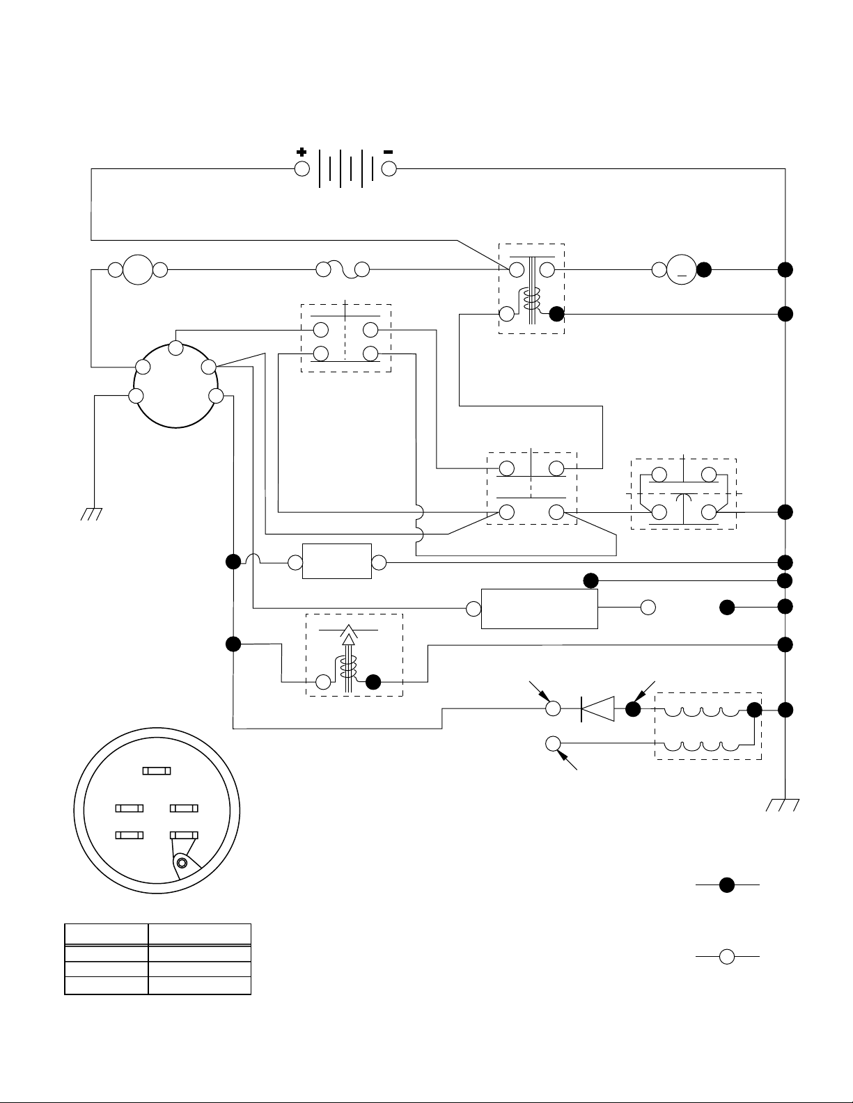
TRACTOR - - MODEL NUMBER MC115T94 (96011001701), PRODUCT NO. 960 11 00-17
SCHEMATIC
A
AMMETER
(OPTIONAL)
RED
B
G
IGNITION
SWITCH
BLACK
RED
BLACK
BATTERY
RED
FUSE
WHITE
RED
M
STARTER
BLACK
SOLENOID
S
M
L
CLUTCH / BRAKE
(PEDAL UP)
WHITE
SEAT SWITCH
(NOT OCCUPIED)
WHITE
BLACK
BLACK
HOUR
ATT'MENT CLUTCH
BLACK
(CLUTCH OFF)
BLACK
BLACK
GROUNDING
CONNECTOR
METER
BLUE
(OPTIONAL)
FUEL
LINE
BLACK
IGNITION
UNIT
TWIN CYL. ENGINES)
SPARK
PLUG
GAP
(2 PLUGS ON
S
M
B
L
IGNITION SWITCH
CIRCUITPOSITION
OFF
M+G
B+LON
B+S+LSTART
28 VOLTS AC MIN. @ 3600 RPM
(CHARGING SYSTEM DISCONNECTED)
DIODE
14 VOLTS AC MIN. @ 3600 RPM (LIGHTS OFF)
ALTERNATOR
FUEL SHUT-OFF SOLENOID
(IF SO EQUIPPED)
CHARGING SYSTEM OUTPUT
3 AMP DC @ 3600 RPM
RED
LIGHTING SYSTEM OUTPUT
5 AMP AC @ 3600 RPM
G
NON-REMOVABLE
WIRING INSULATED CLIPS
CONNECTIONS
NOTE: IF WIRING INSULATED CLIPS
WERE REMOVED FOR
SERVICING OF UNIT, THEY
02492
SHOULD BE REPLACED TO
PROPERLY SECURE YOUR WIRING.
REMOVABLE
CONNECTIONS
3
Page 4
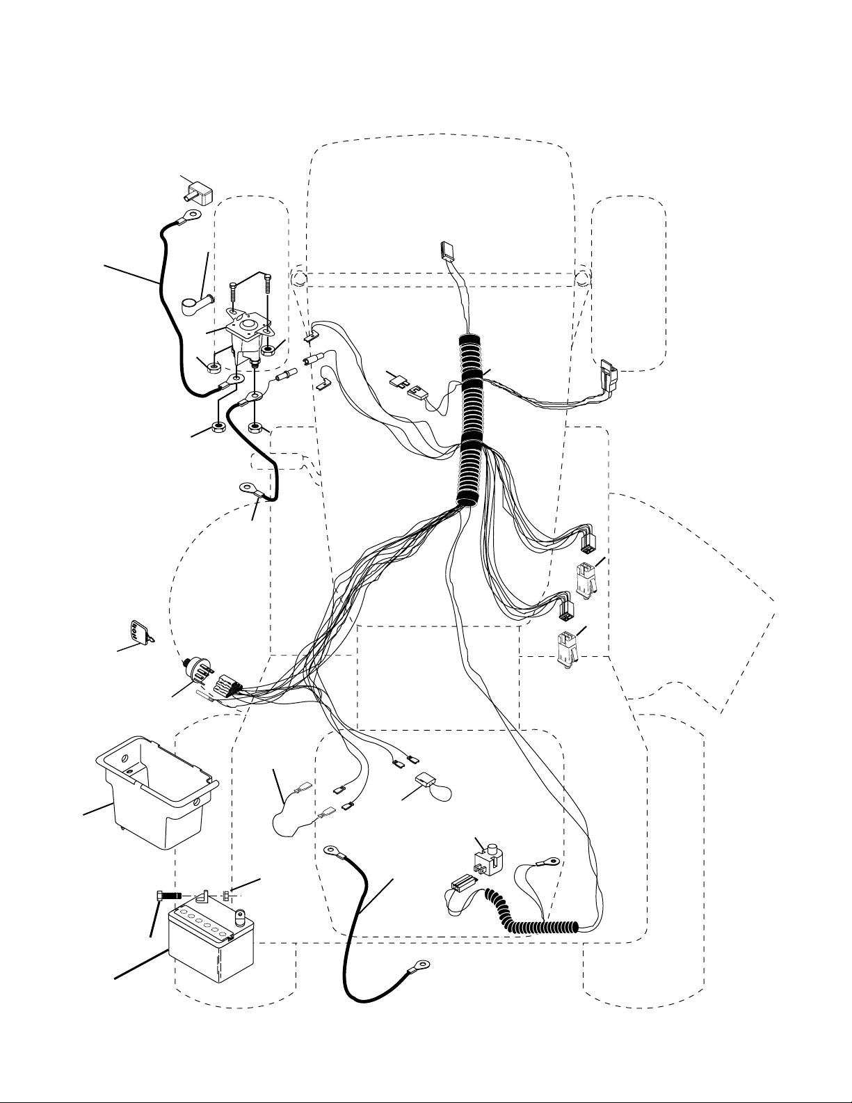
REPAIR PARTS
TRACTOR - - MODEL NUMBER MC115T94 (96011001701), PRODUCT NO. 960 11 00-17
ELECTRICAL
90
42
24
41
33
30
27
43
27
25
27
27
26
40
16
16
48
8
27
2
1
179730
52
29
28
4
Page 5

REPAIR PARTS
TRACTOR - - MODEL NUMBER MC115T94 (96011001701), PRODUCT NO. 960 11 00-17
ELECTRICAL
KEY PART
NO. NO. DESCRIPTION
1 532 16 34-65 Battery 12 Volt 25 Amp
2 874 76 04-12 Bolt Hex Hd 1/4-20 Unc x 3/4
8 532 17 66-89 Battery Box
16 532 17 61-38 Switch Interlock Push-In
24 532 12 47-80 Cable Battery 6 Ga. 11"red
25 532 14 61-47 Cable Battery
26 532 17 51-58 Fuse
27 873 51 04-00 Nut Keps Hex 1/4-20 unc
28 532 12 47-73 Cable Ground 6 Ga. 12"black
29 532 12 13-05 Switch Plunger Nc Gray
30 532 17 55-67 Switch Ign
33 532 14 04-01 Key Ign
40 532 17 97-30 Harness Ign
41 871 11 04-08 Bolt Blk Fin Hex 1/4-20
42 532 13 15-63 Cover Terminal Red
43 532 17 88-61 Solenoid
48 532 14 08-44 Adapter Ammeter
52 532 14 19-40 Protection Wire Loop
90 532 18 04-49 Cover Terminal Battery
NOTE: All component dimensions given in U. S.
inches 1 inch = 25.4 mm.
5
Page 6
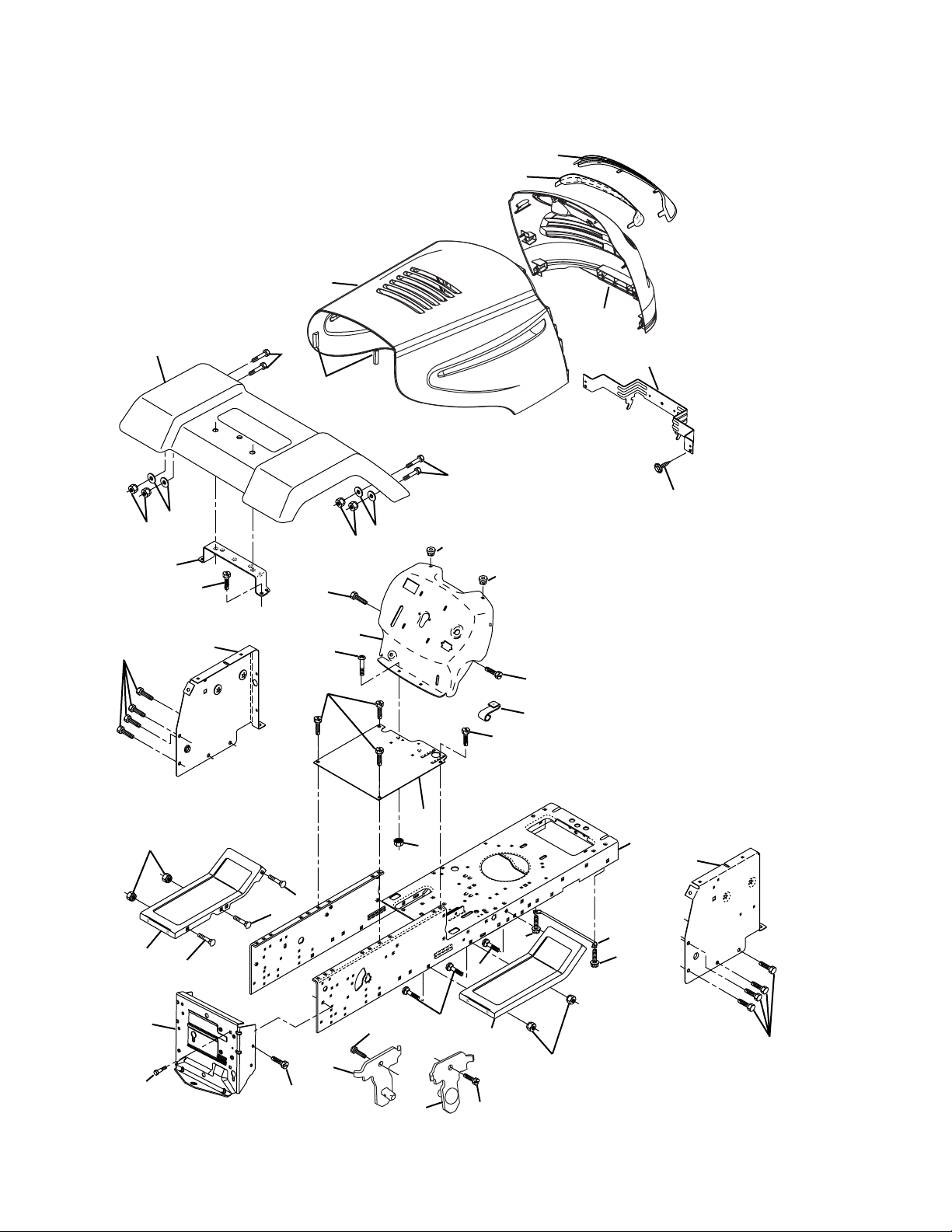
REPAIR PARTS
TRACTOR - - MODEL NUMBER MC115T94 (96011001701), PRODUCT NO. 960 11 00-17
CHASSIS AND ENCLOSURES
29
212
17
28
208
26
30
31
25
209
11
24
209
18
15
209
26
39
24
278
25
5
5
9
209
8
209
33
206
26
6
16
209
35
37
10
2
38
209
205
38
209
35
34
26
205
1
13
145
37
208
Chassis-Elite_Basic_LT_5
6
Page 7

REPAIR PARTS
TRACTOR - - MODEL NUMBER MC115T94 (96011001701), PRODUCT NO. 960 11 00-17
CHASSIS AND ENCLOSURES
KEY PART
NO. NO. DESCRIPTION
1 532 17 46-20 Chassis
2 532 17 65-54 Drawbar
5 532 15 52-72 Bumper, Hood/Dash
6 532 18 25-34 Saddle
8 532 15 51-38 Clip Retainer Slide-On
9 532 19 46-88 Dash
10 872 14 06-08 Bolt, Carriage 3/8-16 x 1
11 532 17 49-96 Panel Dash LH
13 532 18 17-19 Panel Slkscr Dash RH
15 874 18 05-12 Screw Mach TRHD 5/16-18 unc x 3/4
16 873 51 05-00 Nut Keps 5/16-18 Unc
17 532 19 55-50 Hood
18 532 18 49-21 Bumper Hood
24 874 78 06-16 Bolt Fin Hex 3/8-16 unc x 1 Gr. 5
25 819 13 13-12 Washer 13/32 x 13/16 x 12 Ga.
26 873 80 06-00 Nut Lock Hex w/Ins 3/8-16 unc
28 532 19 47-98 Grille/Lens Asm.
30 532 18 12-72 Fender
31 532 13 66-19 Bracket Fender Repl 109873x
33 532 18 30-81 Footrest Pnt LH
34 532 18 30-80 Footrest Pnt RH
35 872 11 06-06 Bolt Rdhd Sht Sqnk 3/8-16 x 3/4
37 817 49 05-08 Screw Thdrol 5/16-18 x 1/2 TYT
38 532 17 57-10 Bracket Asm. Pivot Mower Rear
39 532 17 47-14 Bracket Pivot Laser
145 532 15 65-24 Rod Pivot Chassis/Hood
205 817 49 06-08 Screw Thdrol 3/8-16 x 1/2
206 532 17 01-65 Bolt Shoulder 5/16-18
208 817 67 06-08 Screw Thdrol 3/8-16 x 1/2
209 817 00 06-12 Screw Hex Wsh Thdrol 3/8-16
278 532 19 16-11 Screw 10 x 3/4 Single Lead-Hex
- - - 532 00 54-79 Plug Button Blk 359 Dia Choke
- - 532 19 39-35 Plug Switch Light
NOTE: All component dimensions given in U.S. inches
1 inch = 25.4 mm.
7
Page 8

REPAIR PARTS
TRACTOR - - MODEL NUMBER MC115T94 (96011001701), PRODUCT NO. 960 11 00-17
DRIVE
268
263
57
120
275
10
13
14
112
77
16
52
21
8
263
63
212
12
7
12
18
113
11
30
32
4
3
79
170
6
6
263
26
32
51
30
52
59
61
56
41
5
18
62
35
38
6
39
36
34
66
65
64
50
27
49
47
120
37
70
116
55
202
150
48
151
51
15
96
26
24
19
25
2
77
1
75
74
78
76
29
28
22
26
27
36
35
53
drive-saddle_31
8
Page 9

REPAIR PARTS
TRACTOR - - MODEL NUMBER MC115T94 (96011001701), PRODUCT NO. 960 11 00-17
DRIVE
KEY PART
NO. NO. DESCRIPTION
1 - - - - - - - - - Transaxle, Peerless 205-544C
(Order parts from transaxle manu-
facturer)
2 532 14 66-82 Spring Return Brake T/a Zinc
3 532 12 36-66 Pulley Transaxle 18" tires
4 812 00 00-28 Ring Retainer # 5100-62
5 532 12 15-20 Strap Torque 30 Degrees
6 817 00 05-12 Screw 5/16-18 x 3/4
7 532 16 22-40 Bracket T/A Saddle Shift
8 532 13 16-79 Rod Shifter
10 876 02 04-16 Pin Cotter 1/8 x 1 Cad
11 532 10 57-01 Washer Plate Shf 388 Sq Hole
12 819 15 12-16 Washer 15/32 x 3/4 x 16
13 874 55 04-12 Bolt 1/4-28 Unf Gr 8 W/Patch
14 810 04 04-00 Washer Lock Hvy Helical 1/4
15 874 49 05-44 Bolt Hex Flghd 5/16-18 Gr. 5
16 873 80 05-00 Nut Lock Hx W/Ins 5/16-18 Unc
18 874 78 06-16 Bolt, Fin Hex 3/8-16 Unc x 1 Gr. 5
19 873 80 06-00 Nut Lock 3/8-16 Unc
21 532 10 69-33 Knob
22 532 13 08-04 Rod Brake Blk Zinc 26 840
24 873 35 06-00 Nut Hex Jam 3/8-16 Unc
25 532 10 68-88 Spring Rod Brake 2 00 Zinc
26 819 13 13-16 Washer 13/32 x 13/16 x 16 Ga
27 876 02 04-12 Pin Cotter 1/8 x 3/4 Cad
28 532 17 57-65 Rod Brake Parking
29 532 07 16-73 Cap Brake Parking
30 532 17 49-73 Bracket Mtg Tran sax le
32 874 76 05-12 Bolt Hex Hd 5/16-18unc x 3/4
34 532 17 55-78 Shaft Asm Pedal Foot
35 532 12 01-83 Bearing Nylon Blk 629 Id
36 819 21 16-16 Washer 21/32 x 1 x 16 Ga
37 532 12 49-63 Pin Roll 3/16 x 1"
38 532 17 91-14 Pulley Idler Composite
39 872 11 06-22 Bolt Rdhd 3/8-16 Unc x 2-3/4 Gr. 5
41 532 17 55-56 Keeper Belt Re tain er Idler
47 532 12 77-83 Pulley Idler V Groove Plastic
48 532 15 44-07 Bellcrank Asm
KEY PART
NO. NO. DESCRIPTION
49 532 12 32-05 Retainer Belt Style Spring
50 872 11 06-12 Bolt Carr Sh 3/8-16 x 1-1/2 Gr. 5
51 873 68 06-00 Nut Crownlock 3/8-16 Unc
52 873 68 05-00 Nut Crownlock 5/16-18 Unc
53 532 10 57-10 Link Clutch
55 532 10 57-09 Spring Return Clutch 6 75
56 817 06 06-20 Screw 3/8-16 x 1-1/4
57 532 13 08-01 V-Belt Ground Drive
59 532 16 96-91 Keeper Belt Span Ctr
61 817 12 06-14 Screw 3/8-16 x .875
62 532 12 48-72 Cover Pedal Blk Round
63 532 18 02-19 Engine Pulley
64 532 17 39-37 Bolt Hex
65 810 04 07-00 Washer Lock Hvy Hlcl Spr 7/16
66 532 15 47-78 Keeper Belt Engine Foolproof
70 532 18 02-18 Guide Belt Mower Drive RH
74 532 13 70-57 Spacer Axle
75 532 12 17-49 Washer 25/32 x 1 1/4 x 16 Ga
76 812 00 00-01 E-ring #5133-75
77 532 12 35-83 Key Square 2 0 x 1845/ 1865
78 532 12 17-48 Washer 25/32 x 1-5/8 x 16 Ga
79 532 12 50-96 Key Woodruff
96 532 12 47-88 Retainer Spring 1"
112 819 09 12-10 Washer 9/32 x 3/4 x 10 Ga.
113 532 12 72-85 Strap Torque Lh
116 872 14 06-08 Bolt Rdhd Sq Neck 3/8-16 x 1.00
120 873 90 06-00 Nut Lock Flg 3/8-16
150 532 17 54-56 Spacer Retainer
151 819 13 32-10 Washer 13/32 x 2 x 10
170 532 18 74-14 Keeper Belt T/A
202 872 11 06-14 Bolt, 3/8 - 16 x 1-3/4 Gr. 5
212 532 14 52-12 Nut Flange Hex Lock
263 817 00 06-12 Screw 3/8-16 x 3/4
268 532 18 24-02 Muffl er Guard RH
275 819 13 16-14 Washer 13/32 x 1 x 14 Ga.
NOTE: All component dimensions given in U.S. inches
1 inch = 25.4 mm
9
Page 10

REPAIR PARTS
TRACTOR - - MODEL NUMBER MC115T94 (96011001701), PRODUCT NO. 960 11 00-17
STEERING
38
97
34
39
1
41
42
37
37
36
steering_pl.lt_58
44
88
91
43
68
29
15
15
82
29
15
71
29
68
46
8
17
6
9
2
7
9
5
3
40
47
13
65
32
11
26
28
10
30
67
46
8
6
9
67
67
47
7
9
5
4
43
43
95
8
10
Page 11

REPAIR PARTS
TRACTOR - - MODEL NUMBER MC115T94 (96011001701), PRODUCT NO. 960 11 00-17
STEERING
KEY PART
NO. NO. DESCRIPTION
1 532 18 67-80 Wheel Steering
2 532 17 51-31 Axle Asm
3 532 16 98-40 Spindle Asm LH
4 532 16 98-39 Spindle Asm RH
5 532 12 49-31 Bearing Race Thrust Harden
6 532 12 17-48 Washer 25/32 x 1-5/8 x 16 Ga.
7 819 27 20-16 Washer 27/32 x 1-1/4 x 16 Ga.
8 812 00 00-29 Ring Klip #t5304-75
9 532 12 49-37 Bearing Col Strg Blk
10 532 17 51-21 Link Drag
11 810 04 06-00 Washer Lock Hvy Hlcl Spr 3/8
13 532 13 65-18 Spacer earing Axle Front
15 532 14 52-12 Hexfl ange Lock
17 532 19 07-53 Shaft Asm Strg
26 532 12 68-47 Bushing Link Drag Blk LR
28 819 13 14-16 Washer 13/32 x 7/8 x 16 Ga.
29 817 00 06-12 Screw 3/8-16 x 3/4
30 876 02 04-12 Pin Cotter 1/8 x 3/4 Cad
32 532 13 04-65 Rod Tie Wire Form 19 75 Mech
34 810 04 05-00 Washer Lock Hvy HLCL Spr. 5/16
36 532 15 50-99 Bushing Strg 5/8 Id Dash
37 532 15 29-27 Screw
38 532 19 29-16 Cap Wheel Steer
39 819 18 38-12 Washer 9/16 ID x 2-3/8 OD 12 Ga.
40 873 54 06-00 Nut Crownlock 3/8-24
41 532 18 67-37 Adaptor Wheel Strg
42 532 16 96-33 Boot Steering
43 532 12 17-49 Washer 25/32 x 1-1/4 x 16 Ga.
44 532 19 07-52 Extension Steering
46 532 12 12-32 Cap Spindle Fr Top Blk
47 532 18 32-26 Fitting Grease
65 532 16 03-67 Spacer Brace Axle
67 872 11 06-18 Bolt RdHd Sqnk 3/8-16 x 2-1/4
68 532 16 98-27 Brace Axle
71 532 17 51-46 Steering Asm
82 532 16 98-35 Bracket Susp Chassis Front
85 532 13 38-35 Fastener Christmas Tree
88 532 17 51-18 Bolt shoulder 7/16-20
91 532 17 55-53 Clip Steering
95 532 18 89-67 Washer Hardened
97 874 78 05-64 Bolt 5/16-18 UNC x 4" L Gr 5
NOTE: All component dimensions given in U.S. inches
1 inch = 25.4 mm.
11
Page 12

REPAIR PARTS
TRACTOR - - MODEL NUMBER MC115T94 (96011001701), PRODUCT NO. 960 11 00-17
ENGINE
2
32
3
72
1
25
78
38
44
81
14
78
62
13
4
31
46
37
33
40
29
OPTIONAL EQUIPMENT
Spark Arrester
33
45
23
engine-bs.1cyl_38
12
Page 13

REPAIR PARTS
TRACTOR - - MODEL NUMBER MC115T94 (96011001701), PRODUCT NO. 960 11 00-17
ENGINE
KEY PART
NO. NO. DESCRIPTION
1 532 17 05-51 Control Throttle /Choke
2 817 72 04-08 Screw Hex Thd Cut 1/4-20 x 5/8 T
3 - - - - - - - - Engine B&S Model 217707
(Order Parts from Engine Manufacturer)
4 532 17 97-58 Muffl er Exhaust
13 532 16 52-91 Gasket
14 532 14 84-56 Tube Drain Oil Easy
23 532 16 98-37 Shield Browning/Debris Guard
25 532 19 06-95 Control Choke
29 532 13 71-80 Arrestor Spark
31 532 18 77-50 Tank Fuel
32 532 14 05-27 Cap Asm Fule Top Vent N/Lany
33 532 12 34-87 Clamp Hose Blk
37 532 13 70-40 Line Fuel 20"
38 532 18 16-54 Plug Drain Oil Easy
40 532 12 40-28 Bushing Snap
44 817 67 04-12 Screw Hexwsh Thdrol 3/8-16 x 3/4
45 817 00 06-12 Screw 3/8-16 x 3/4
46 819 09 14-16 Washer 9/32 x 7/8 x 16 Ga.
62 810 04 05-00 Washer Lock Hvy HLCL Spr 5/16
72 871 07 05-12 Screw 5/16-18 x 3/4
78 817 06 06-20 Screw 3/8-16 x 1-1/4
81 873 51 04-00 Nut Keps Hex 1/4-20 unc
NOTE: All component dimensions given in U.S. inches
1 inch = 25.4 mm
13
Page 14

REPAIR PARTS
TRACTOR - - MODEL NUMBER MC115T94 (96011001701), PRODUCT NO. 960 11 00-17
SEAT
1
8
8
9
7
5
6
22
14
9
7
10
24
26
16
25
15
23
13
17
seat_lt.bolt_1
KEY PART
NO. NO. DESCRIPTION
1 532 17 53-89 Seat
2 532 14 05-51 Bracket Seat Pivot
3 871 11 06-16 Bolt Hex 3/8 - 16 x 1
4 819 13 16-10 Washer 13/32 x 1 x 10 Ga.
5 532 14 50-06 Clip Push-In Hinged
6 873 80 06-00 Nut Lock Hex w/Ins 3/8 - 16
7 532 12 41-81 Spring Seat Cprsn 2 250 Blk Zi
8 817 00 06-16 Screw 3/8-16 x 1.5
9 819 13 16-14 Washer 13/32 x 1 x 14 Ga.
10 532 18 24-93 Pan Pnt Seat (Blk)
12 532 12 12-46 Bracket Pnt Mounting Switch
13 532 12 12-48 Bushing Snap Blk Nyl
12
2
5
4
3
KEY PART
NO. NO. DESCRIPTION
14 872 05 04-12 Bolt Rdhd Sht Nk 1/4 - 20 x 1 -1/2
15 532 13 43-00 Spacer Split .28 x .96
16 532 12 12-50 Spring Cprsn
17 532 12 39-76 Nut Lock 1/4 Lge Flg
21 532 17 18-52 Bolt Shoul der 5/16-18 unc-2A
22 873 80 05-00 Nut Lock Hex w/Ins 5/16 - 18
23 871 11 08-14 Bolt Hex Black
24 819 17 19-12 Washer 17/32 x 1-3/16 x 12 Ga.
25 532 12 70-18 Bolt Shoul der 5/16-18 x .62
26 810 04 08-00 Washer Lock Hvy Hlcl Spr 1/2
NOTE: All component dimensions given in U.S. inches
1 inch = 25.4 mm.
21
14
Page 15

REPAIR PARTS
TRACTOR - - MODEL NUMBER MC115T94 (96011001701), PRODUCT NO. 960 11 00-17
DECALS
2
5
7
12
12
9
4
15
4
10
8
3
6
KEY PART
NO. NO. DESCRIPTION
2 532 18 58-81 Decal, Steering Wheel
3 532 15 97-37 Decal, Brake/Clutch
4 532 15 97-36 Decal, Hot Muffl er
5 532 19 44-55 Decal, Fender
6 532 18 04-32 Decal, DB/CE
7 532 14 54-98 Decal, Read Owner's Manual
8 532 13 68-32 Decal, V-Belt Sch.
9 532 14 08-37 Decal, Parking Brake
WHEELS & TIRES
1
2
6
5,8
4,10
7
3,9
11
KEY PART
NO. NO. DESCRIPTION
10 532 18 21-66 Decal, Cut Finger
12 532 18 90-24 Decal, Hood RH/LH
15 532 14 50-05 Decal, Caution, Battery
- - 532 16 25-98 Decal, Drawbar
- - 532 13 83-11 Decal, Handle Lft Height Adj.
- - 532 19 41-00 Manual, Operator's, Euro
- - 532 19 41-01 Manual, Operator's, Scan
- - 532 19 68-66 Manual Parts
KEY PART
NO. NO. DESCRIPTION
1 532 05 91-92 Cap, Tire valve
2 532 06 51-39 Stem, Valve
3 532 12 41-57 Tire, Front
4 532 05 99-04 Tube, Front (Service item only)
5 532 18 33-37 Rim assembly, 6" front
6 532 12 49-57 Fitting, Grease (Front wheel only)
7 532 12 49-59 Bearing, Flange (Front wheel only)
8 532 18 33-38 Rim assembly, 8" rear
9 532 12 39-69 Tire, Rear
10 532 12 49-26 Tube, Rear (Service item only)
11 532 17 50-39 Cap, Hub Axle
- - 532 14 43-34 Sealant, Tire (10 oz. Tube)
wheel_1
NOTE: All component dimensions given in U.S. inches
1 inch = 25.4 mm
15
Page 16

REPAIR PARTS
TRACTOR - - MODEL NUMBER MC115T94 (96011001701), PRODUCT NO. 960 11 00-17
MOWER DECK
152
42_clut
158
ch_mod_7
21
67
185
55
123
54
89
107
45
122
40
2
4
56
3
8
113
146
36
45
108
89
40
150
36
33
31
53
32
148
68
2
110
1
109
30
21
88
87
89
26
28
25
24
96
97
21
2
2
86
16
3
2
15
29
14
21
23
5
6
4
19
21
149
13
11
10
9
27
8
38_deck-manual_2
16
Page 17

REPAIR PARTS
TRACTOR - - MODEL NUMBER MC115T94 (96011001701), PRODUCT NO. 960 11 00-17
MOWER DECK
KEY PART
NO. NO. DESCRIPTION
1 532 17 02-80 Mower Housing Assembly
2 872 14 05-06 Bolt Carriage 5/16-18 x 3/4
3 532 13 80-17 Bracket Asm Fr. Sway Bar
4 532 16 99-70 Bracket Deck Sway Bar 38"/42"
5 532 12 46-70 Retainer Spring
6 532 17 80-24 Sway Bar Deck
8 532 85 08-57 Bolt 3/8-24 x 1.25 Gr. 8
9 810 03 06-00 Washer, Lock 3/8
10 532 14 02-96 Washer, Hardened
11 532 13 84-97 Blade Mower
13 532 13 76-45 Shaft Assembly, Mandrel, Vented
(Includes Key Number 6)
14 532 12 87-74 Housing, Mandrel, Vented
15 532 11 04-85 Bearing, Ball, Mandrel
16 532 17 44-93 Stripper, Mower Deck
19 532 13 28-27 Bolt, Shoulder
21 873 68 05-00 Nut
23 532 13 76-07 Bracket, Mower Defl ector
24 532 10 53-04 Cap, Sleeve
25 532 12 37-13 Spring, Torsion, Defl ector
26 532 11 04-52 Nut, Push
27 532 17 59-43 Shield, Defl ector
28 819 11 10-16 Washer 11/32 x 5/8 x 16 Ga.
29 532 10 67-35 Rod, Hinge
30 532 17 39-84 Screw Thdrol. Hex
31 532 18 76-90 Washer, Spacer
32 532 15 35-32 Pulley, Mandrel
33 532 17 83-42 Nut, Toplock
36 532 13 14-94 Pulley, Idler, Flat
40 873 68 06-00 Nut, Crownlock 3/8-16 unc
45 532 12 47-88 Retainer
53 532 13 08-40 Brake Assembly
KEY PART
NO. NO. DESCRIPTION
54 532 17 85-15 Washer, Hardened
55 532 13 38-40 Idler Arm Assembly
56 532 16 57-23 Spacer, Retainer
67 532 10 69-32 Knob
68 532 18 02-14 V-Belt
86 532 12 50-74 Runner, LH
87 532 12 87-72 Runner, RH
88 819 11 12-16 Washer 11/32 x 3/4 x 16 Ga.
89 819 13 13-11 Washer 13/32 x 13/16 x 11 Ga.
96 874 93 06-20 Bolt 3/8-16 x 1-1/4
97 873 93 06-00 Nut Centerlock 3/8-16 unc
107 532 13 35-02 Spacer Retainer
108 532 13 35-03 Stiffener, Idler Arm
109 874 76 06-40 Bolt, Hex Hd 3/8-16 x 2-1/2
110 532 14 25-87 Upstop Deck Front 38"
113 817 06 05-12 Screw 5/16-1/ x 3/4
122 532 13 12-89 Rod, Brake LH
123 532 16 99-71 Rod, Brake RH
146 532 16 58-91 Bolt Carriage Idler
148 532 16 90-22 Spring Return Idler
149 532 16 58-98 Retainer Spring Yellow
150 819 09 12-10 Washer 9/32 x 3/4 x 10 Ga.
152 532 17 27-58 Clutch Cable 38"/46"
158 817 72 04-08 Screw Hex Thd Cut 1/4-20 x 5/8
185 532 18 82-34 Head Asm. Cable Clutch
- - 532 13 07-94 Mandrel Assembly (Includes Housing, Shaft, and Shaft Hardware Only
- Pulley Not Included)
- - 532 18 13-80 Mower Replacement, Complete
NOTE: All component dimensions given in U.S. inches
1 inch = 25.4 mm
17
Page 18

REPAIR PARTS
TRACTOR - - MODEL NUMBER MC115T94 (96011001701), PRODUCT NO. 960 11 00-17
MOWER LIFT
7
8
5
13
13
11
19
31
32
31
32
13
12
3
4
2
1
6
6
5
4
13
20
15
17
16
18
20
20
19
20
15
lift-rh.1piece_3
KEY PART
NO. NO. DESCRIPTION
1 532 15 94-60 Wire Asm Inner/Sprg w/plunger
2 532 15 94-71 Shaft Asm Lift RH
3 532 10 57-67 Pin Groove
4 812 00 00-02 E Ring #5133-62
5 819 21 16-21 Washer 21/32 x 1 x 21 Ga
6 532 12 01-83 Bearing Nylon Blk 629 Id
7 532 10 94-13 Grip Handle Bicycle Matte Blk
8 532 12 45-26 Button Plunger Black
11 532 13 98-65 Link Lift LH Fixed Length
12 532 13 98-66 Link Lift RH Fixed Length
13 532 12 46-70 Retainer Spring
KEY PART
NO. NO. DESCRIPTION
15 532 17 32-88 Link Front
16 873 35 08-00 Nut Jam Hex 1/2-13 Unc
17 532 17 56-89 Trunnion
18 873 80 08-00 Nut Lockw/Wsh 1/2-13 Unc
19 532 13 98-68 Arm Suspension Rear
20 532 16 35-52 Retainer, Spring
31 532 16 98-65 Bearing Pvt Lift
32 873 54 06-00 Nut Crownlock 3/8-24
NOTE: All component dimensions given in U.S. inches
1 inch = 25.4 mm.
18
Page 19

T
E
C
U
M
S
E
H
®
SERVICE
®
T
E
C
U
Issued January 1980
Revised January 1991
M
H
E
S
POLICY
WARRANTY
LIMITED WARRANTIES
FOR
NEW PEERLESS GEAR POWER TRAIN COMPONENTS
A. Products Warranted
Peerless Gear and Machine Division of Tecumseh Products Company (“Tecumseh”), subject to the limitations contained below,
will, at its option, repair or replace, without charge for parts or labor only, any part of a new Power Train Component (which as used
herein means and includes the transaxle, gear box, trans mis sion, differential and right angle drives, and any part of the Power Train
Component), EXCEPT any new Power Train Component incorporated in equipment used for commercial or rental pur pos es, which is
found upon examination by any Tecumseh Au tho rized Service Outlet or by Tecumseh’s factory in Grafton, Wis con sin, to be DEFECTIVE
IN MATERIAL AND/OR WORKMANSHIP if re ceived by Tecumseh or a Tecumseh Authorized Service Outlet for such examination within
TWO YEARS from the date of sale to the original consumer purchaser of Peerless Series 820, 900, 910, 915, 920, 930 transaxles and
Series 1100 angle drive and ONE YEAR for all other Peerless products. New Power Train Components incorporated in equipment used for
commercial purposes are warranted in the same manner and to the same extent EXCEPT such Power Train Components are warranted
for NINETY (90) DAYS ONLY, and must be received by Tecumseh or by a Tecumseh Au tho rized Service Outlet for such examination
within 90 days from the date of sale to the original purchaser. New Power Train Com po nents Incorporated in equipment used for rental
purposes are warranted in the same manner and to the same extent EXCEPT such Power Train Components are warranted for THIRTY
(30) DAYS ONLY, and must be received by Tecumseh or a Tecumseh Authorized Service Outlet within 30 days from the date of sale to
the original purchaser.
B. Products And Items Not Warranted
1. Alterations or Modifi cations of Power Train Components.
2. Accidents, Normal Maintenance, Failure to follow the Original Equipment Man u fac tur er’s Manual.
This warranty covers only parts of new Power Train Components which are found upon examination to be defective in material
or workmanship as delivered to the original purchaser. This warranty does not cover defects caused by depreciation or damage caused
by normal wear, accidents, improper main te nance, improper use or abuse of the product, failure to follow the instructions contained in
an Instruction Manual for the operation of the Power Train Component and parts. The cost of normal maintenance and replacement of
service items which are not defective shall be paid for by the original purchaser.
C. Securing Warranty Service
Warranty service can be arranged for by contacting either a Tecumseh Authorized Service Outlet (any Tecumseh Registered
Service Dealer, Tecumseh Authorized Service Distributor, or Tecumseh Central Warehouse Distributor) or by contacting Tecumseh, c/o
Service Manager, Engine and Transmission Group Service Division, 900 North Street, Grafton, Wisconsin 53024. Warranty service
can only be performed by a Tecumseh Authorized Service Outlet or by Tecumseh at its factory in Grafton, Wisconsin. At the time of
requesting warranty service, evidence must be presented of the date of sale to the original purchaser. The purchaser shall pay any
charges for making service calls and/or for transporting the product to and from the place where the inspection and/or warranty work
is performed. The purchaser shall be responsible for any damage or loss incurred in connection with the transportation of Power Train
Components and/or part(s) of the Power Train Components submitted for inspection and/or warranty work.
D. Limitation of Damages and Implied Warranties
The foregoing EXPRESSED WARRANTY IS IN LIEU OF ALL OTHER EXPRESS WARRANTIES. Neither Tecumseh nor any
of its affi liates makes any warranties, representations or promises, written or oral, as to the quality of the Power Train Component or any
of its parts, other than as set forth herein.
ANY IMPLIED WARRANTY OF MERCHANTABILITY OR FITNESS FOR A PARTICULAR PURPOSE, TO THE EXTENT THAT
EITHER MAY APPLY TO ANY PART(S) OF POWER TRAIN COMPONENTS, SHALL BE LIMITED IN DURATION TO THE PERIODS
OF THE EXPRESSED WARRANTIES DEFINED IN PARAGRAPH A HEREOF. IN NO EVENT WILL TECUMSEH BE LIABLE FOR ANY
INCIDENTAL, CONSEQUENTIAL OR SPECIAL DAMAGES AND/OR EXPENSES. Some states do not allow limitations on how long
an implied warranty lasts or the exclusion or limitation of incidental or consequential damages, so the above limitation(s) or exclusion(s)
may not apply to you. This warranty gives you specifi c legal rights and you may also have other legal rights which vary from state to
state.
E. No Dealer Warranty
Tecumseh neither assumes nor authorizes any other person, natural or corporate, to assume for Tecumseh any other obligations
or liabilities in connection with or with respect to any part(s) of a Power Train Component. The seller or dealer of part(s) of a Power Train
Component has no authority, whatsoever, to make any representations or promises on behalf of Tecumseh or to modify the terms or
limitations of Tecumseh’s warranty in any way.
19
Page 20

www.electrolux.com/mcculloch
 Loading...