

Page 1

REPAIR PARTS MANUAL
MODEL NO . M11597 (96011023409)
LAWN TRACTOR
www.mcculloch.biz
532 44 02-78 Rev. 3
Page 2

HOW TO USE THIS MANUAL
This manual is designed to provide the customer with a means to identify the parts on his/her tractor
when ordering repair parts. The illustrations may or may not represent the actual assemblies; therefore,
it is not recommended to use this manual as a guide to assemble or disassemble the tractor. Some
hardware and parts are drawn larger in order to more readily identify them.
Each tractor has its own model number.
The model number for your tractor can be found on the fender under the seat.
When ordering parts, always give the following information:
• Product - “Tractor”
• Model Number - “
• Part Number
• Part Description
M11597 96011023409
”
TABLE OF CONTENTS
SCHEMA TIC ................................................................................................................3
ELECTRICAL ............................................................................................................4-5
CHASSIS ..................................................................................................................6-7
DRIVE........................................................................................................................8-9
ENGINE .................................................................................................................10-11
STEERING ............................................................................................................12-13
MOWER DECK .....................................................................................................14-15
MOWER LIFT .............................................................................................................16
SEAT ..........................................................................................................................17
DECALS .....................................................................................................................18
2
Page 3
TRACTOR - - MODEL NUMBER M11597 (96011023409), PRODUCT NO. 960 11 02-34
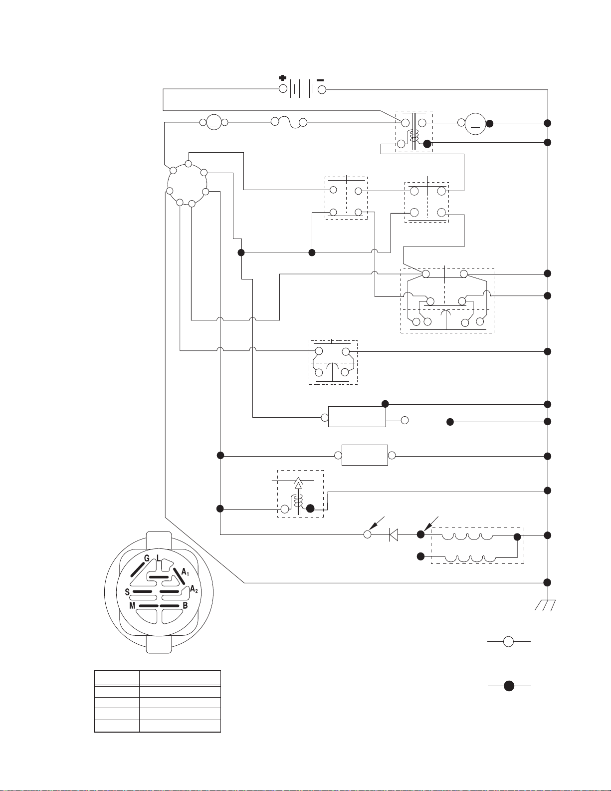
SCHEMATIC
SCH01
BATTERY
SOLENOID
A
AMMETER
(OPTIONAL)
S
B
M
A1
G
L
A2
BLUE
DERDER
FUSE
WHITE
BLACK
BLACK
REVERSE SWITCH
NOT IN REVERSE
BLACK
RED
CLUTCH / BRAKE
(PEDAL UP)
ATTACHMENT CLUTCH
(CLUTCH OFF)
(NOT OCCUPIED)
GRAY
SHORTING CONNECTOR
STARTER
M
BLACK
SEAT SWITCH
BLACK
GRAY
BLACK
IGNITION SWITCH
CIRCUITPOSITION
OFF
RUN/OVERRIDE
M+G+A1
B+S+A1START
B+A1
B+A1RUN
“MAKE”
L+A2
BLACK/WHITE
IGNITION
UNIT
ON TWIN CYL. ENGINES)
BLUE
RED
FUEL SHUT-OFF
BLUE
SOLENOID
(IF EQUIPPED)
HOUR
METER
(OPTIONAL)
CHARGING SYSTEM OUTPUT
3 AMP DC @ 3600 RPM
DIODE
WIRING INSULATED CLIPS
NOTE: IF WIRING INSULATED CLIPS
WERE REMOVED FOR SERVICING OF
UNIT, THEY SHOULD BE RE-INSTALLED
TO PROPERLY SECURE YOUR WIRING.
SPARK PLUGS
GAP
(2 PLUGS
BLACK
28 VOLTS AC MIN. @ 3600 RPM
(CHARGING SYSTEM DISCONNECTED)
STATOR
NON-REMOVABLE
REMOVABLE
CONNECTIONS
CONNECTIONS
3
Page 4
TRACTOR - - MODEL NUMBER M11597 (96011023409), PRODUCT NO. 960 11 02-34
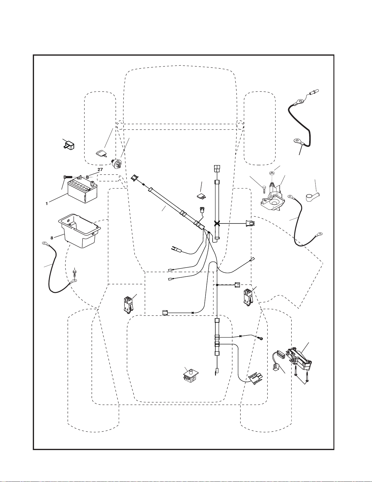
ELECTRICAL
L04
33
90
2
30
26
41
27
43
24
42
28
40
25
55
16
16
94
29
92
93
4
Page 5

TRACTOR - - MODEL NUMBER M11597 (96011023409), PRODUCT NO. 960 11 02-34
ELECTRICAL
KEY PART
NO. NO. DESCRIPTION
1 532 14 49-24 Battery 20 Amp
2 874 76 04-12 Bolt Hex Hd 1/4-20 unc x 3/4
8 532 17 66-89 Battery Box
16 532 17 61-38 Switch Interlock Push-In
24 532 42 12-99 Cable Battery 6 Ga. 11" Red
25 532 42 12-97 Cable Battery
26 532 17 51-58 Fuse
27 873 51 04-00 Nut Keps Hex 1/4-20 unc
28 532 42 12-98 Cable Ground 6 Ga. 12" Black
29 532 19 27-49 Switch Seat
30 532 19 33-50 Switch Ign
33 532 41 19-35 Key/Chain
40 532 19 74-27 Harness Ign
41 871 11 04-08 Bolt Blk Fin Hex 1/4-20
42 532 13 15-63 Cover Terminal Red
43 532 19 25-07 Solenoid
55 817 00 06-12 Screw 3/8-16 x 3/4
90 532 43 53-95 Cover Terminal Battery
92 532 19 66-15 Harness Pigtail Consle ROS
93 532 19 25-40 Screw Plastite 10-14 x 2.0
94 532 19 18-34 Module Reverse ROS
NOTE: All component dimensions given in U. S. inches
1 inch = 25.4 mm.
5
Page 6
TRACTOR - - MODEL NUMBER M11597 (96011023409), PRODUCT NO. 960 11 02-34
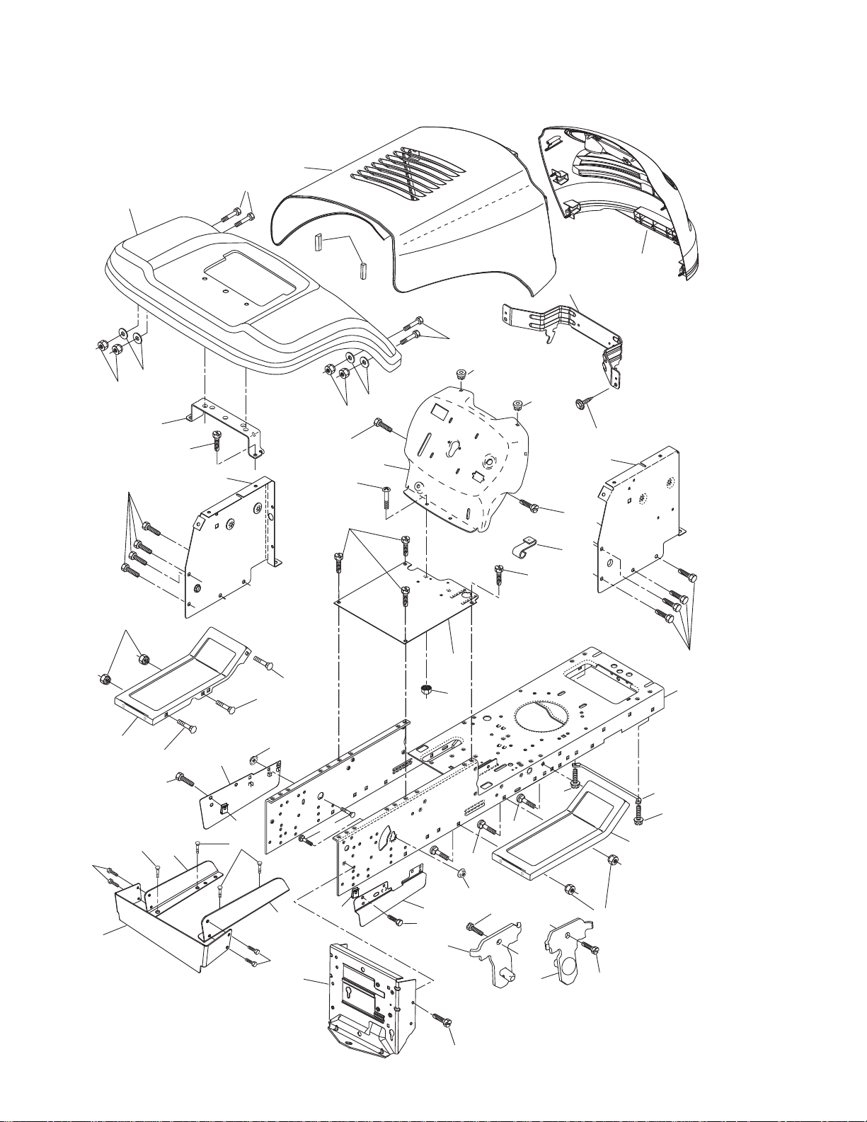
CHASSIS AND ENCLOSURES
17
24
30
18
28
39
24
26
33
208
26
25
31
10
209
11
311
35
141
209
209
209
15
26
25
5
5
278
9
209
6
16
13
209
8
208
1
152
317
209
314
316
313
209
315
152
37
35
205
209
38
26
205
35
141
313
2
310
314
38
209
145
37
34
Chassis-LT_Alpha_2_r1
6
Page 7

TRACTOR - - MODEL NUMBER M11597 (96011023409), PRODUCT NO. 960 11 02-34
CHASSIS AND ENCLOSURES
KEY PART
NO. NO. DESCRIPTION
1 532 17 46-20 Chassis
2 532 17 65-54 Drawbar
5 532 15 52-72 Bumper, Hood/Dash
6 532 18 44-19 Saddle
8 532 15 51-38 Clip, Retainer
9 532 19 46-88 Dash
10 872 14 06-08 Bolt, Carriage 3/8-16 x 1
11 532 17 49-96 Panel Dash LH
13 532 18 17-19 Panel, Slkscr Dash RH
15 874 18 05-12 Screw 5/16-18 x 3/4
16 873 51 05-00 Nut Keps 5/16-18 x 3/4
17 532 40 61-79 Hood
18 532 18 49-21 Bumper Hood
24 874 78 06-16 Bolt Fin Hex 3/8-16 unc x 1 Gr. 5
25 819 13 13-12 Washer 13/32 x 13/16 x 12 Ga.
26 873 80 06-00 Nut Lock Hex w/Ins 3/8-16 unc
28 532 44 03-57 Grille
30 532 40 48-52 Fender
31 532 13 66-19 Bracket Fender Repl 109873x
33 532 18 25-07 Footrest Pnt LH
34 532 18 25-08 Footrest Pnt RH
35 872 11 06-06 Bolt Rdhd Sht Sqnk 3/8-16 x 3/4
37 817 49 05-08 Screw Thdrol 5/16-18 x 1/2 TYT
38 532 17 57-10 Bracket Asm. Pivot Mower Rear
39 532 18 75-68 Bracket Pivot
141 873 90 06-00 Nut Lock Flg 3/8-16 unc
145 532 40 91-67 Rod Pivot Chassis/Hood
152 817 72 04-08 Screw THd Cut 1/4-20 x 1/2
205 817 49 06-08 Screw Thdrol 3/8-16 x 1/2
208 817 67 06-08 Screw Thdrol 3/8-16 x 1/2
209 817 00 06-12 Screw Hex Wsh Thdrol 3/8-16
278 532 41 63-58 Screw 10 x .750 BOS Thread
310 532 42 27-66 Shield Lower RH
311 532 42 27-67 Shield Lower LH
313 532 19 66-88 Clips Threaded
314 532 13 77-29 Screw Thd Roll 1/4-20 x 5/8
315 532 42 27-71 Shield Upper RH
316 532 42 27-72 Shield Upper LH
317 532 42 28-60 Shield Rear
- - 532 19 39-35 Plug Switch Light
- - 532 00 54-79 Plug Button Blk 359 Dia Choke
NOTE: All component dimensions given in U.S. inches
1 inch = 25.4 mm.
7
Page 8

TRACTOR - - MODEL NUMBER M11597 (96011023409), PRODUCT NO. 960 11 02-34
DRIVE
84
13
16
77
14
112
85
11
197
52
85
30
69
80
81
32
10
57
268
120
263
275
89
63
120
159
198
161
158
162
21
169
263
112
14
83
163
18
8
4
3
113
51
82
165
156
56
41
168
38
166
39
66
65
64
50
70
116
55
202
150
48
5
79
170
18
6
32
30
6
52
62
6
35
36
37
27
49
151
51
47
120
34
145
96
26
25
28
26
36
35
53
26
2
19
24
77
74
78
76
29
22
1
75
10
Drive-LT_Peerless_fender_10
27
8
Page 9

TRACTOR - - MODEL NUMBER M11597 (96011023409), PRODUCT NO. 960 11 02-34
DRIVE
KEY PART
NO. NO. DESCRIPTION
1 - - - - - - - - - Transaxle, Peerless 205-544C
2 532 14 66-82 Spring Return Brake T/A Zinc
3 532 12 36-66 Pulley Transaxle 18" Tires
4 812 00 00-28 Ring Retainer # 5100-62
5 532 12 15-20 Strap Torque 30 Degrees
6 817 06 05-12 Screw 5/16-18 x 3/4
8 532 19 27-06 Rod Shifter
10 876 02 04-16 Pin Cotter 1/8 x 1 Cad
11 532 10 57-01 Washer Plate Shf 388 Sq Hole
13 874 55 04-12 Bolt 1/4-28 unf Gr. 8 w/Patch
14 810 04 04-00 Washer Lock Hvy Helical 1/4
16 873 80 05-00 Nut Lock Hx w/Ins 5/16-18 unc
18 874 78 06-16 Bolt, Fin Hex 3/8-16 unc x 1 Gr. 5
19 873 80 06-00 Nut Lock 3/8-16 unc
21 532 10 69-33 Knob
22 532 13 08-04 Rod Brake Blk Zinc 26 840
24 873 35 06-00 Nut Hex Jam 3/8-16 unc
25 532 10 68-88 Spring Rod Brake 2 00 Zinc
26 819 13 13-16 Washer 13/32 x 13/16 x 16 Ga.
27 876 02 04-12 Pin Cotter 1/8 x 3/4 Cad
28 532 17 57-65 Rod Brake Parking
29 532 07 16-73 Cap Brake Parking
30 532 17 49-73 Bracket Mtg Tran sax le
32 874 76 05-12 Bolt Hex Hd 5/16-18 unc x 3/4
34 532 17 55-78 Shaft Asm Pedal Foot
35 532 12 01-83 Bearing Nylon Blk 629 ID
36 819 21 16-16 Washer 21/32 x 1 x 16 Ga.
37 532 12 49-63 Pin Roll 3/16 x 1"
38 532 17 91-14 Pulley Idler Composite
39 872 11 06-22 Bolt Rdhd 3/8-16 unc x 2-3/4 Gr. 5
41 532 17 55-56 Keeper Belt Re tain er Idler
47 532 12 77-83 Pulley Idler V Groove Plastic
48 532 15 44-07 Bellcrank Asm
49 532 12 32-05 Retainer Belt Style Spring
50 872 11 06-12 Bolt Carr Sh 3/8-16 x 1-1/2 Gr. 5
51 873 68 06-00 Nut Crownlock 3/8-16 unc
52 873 68 05-00 Nut Crownlock 5/16-18 unc
53 532 19 96-52 Link Clutch
55 532 10 57-09 Spring Return Clutch 675
56 817 06 06-20 Screw 3/8-16 x 1-1/4
57 532 13 82-55 V-Belt Ground Drive
62 532 12 48-72 Cover Pedal Blk Round
63 532 17 54-10 Engine Pulley
64 532 17 39-37 Bolt Hex
65 810 04 07-00 Washer Lock Hvy Hlcl Spr 7/16
66 532 15 47-78 Keeper Belt Engine Foolproof
69 532 14 24-32 Screw Hex Wsh Hi-Lo 1/4 x 1/2 unc
KEY PART
NO. NO. DESCRIPTION
70 532 13 46-83 Guide Belt Mower Drive RH
74 532 13 70-57 Spacer Axle
75 532 12 17-49 Washer 25/32 x 1 1/4 x 16 Ga.
76 812 00 00-01 E-ring #5133-75
77 532 12 35-83 Key Square 2 0 x 1845/ 1865
78 532 12 17-48 Washer 25/32 x 1-5/8 x 16 Ga.
79 532 12 50-96 Key Woodruff
80 532 13 14-86 Arm Shift Transaxle
81 532 16 55-94 Shaft Asm. Cross Taper
82 532 16 57-11 Spring Torsion Shift
83 819 17 12-16 Washer 17/32 x 3/4 x 16 Ga.
84 532 16 62-28 LinkTransaxle
85 532 15 03-60 Nut Lock Center 1/4-28
89 532 19 49-71 Console, SVC Shift
96 532 12 47-88 Retainer Spring 1"
112 819 09 12-10 Washer 9/32 x 3/4 x 10 Ga.
113 532 12 72-85 Strap Torque LH
116 872 14 06-08 Bolt Rdhd Sq Neck 3/8-16 x 1.00
120 873 90 06-00 Nut Lock Flg 3/8-16
145 874 49 05-40 Bolt Hex 5/16-18 x 2-1/2 Gr. 5
150 532 17 54-56 Spacer Retainer
151 819 13 32-10 Washer 13/32 x 2 x 10
156 532 16 60-02 Washer Srrtd 5/16 ID x 1.0 x .125TK
158 532 43 74-58 Bracket Shift Mount
159 532 18 39-00 Hub Shift
161 872 14 04-06 Bolt RDHD SQNK 1/4-20 x 3/4 Gr.5
162 873 68 04-00 Nut Crownlock 1/4-20 unc
163 874 78 04-16 Bolt Hex Fin 1/4-20 unc x 1 Gr. 5
165 532 43 82-50 Bracket Pivot Lever
166 817 49 05-10 Screw 5/16-18 x 5/8 TT Yellow
168 532 16 54-92 Shoulder Bolt 5/16 -18 x .561
169 532 16 55-81 Plate, Fastening
170 532 18 74-14 Keeper Belt T/A
197 532 16 96-13 Nyliner Snap-in 5/8" ID
198 532 16 98-45 Washer Nyl
202 872 11 06-14 Bolt, 3/8-16 x 1-3/4 Gr. 5
263 817 00 06-12 Screw, 3/8-16 x 3/4
268 532 18 24-02 Guard, Muffler
275 819 13 16-14 Washer, 13/32 x 1 x 14 Ga.
NOTE: All component dimensions given in U.S. inches
1 inch = 25.4 mm
9
Page 10

TRACTOR - - MODEL NUMBER M11597 (96011023409), PRODUCT NO. 960 11 02-34
ENGINE
3
32
2
1
81
25
44
46
78
122
78
45
23
33
72
13
4
31
33
40
29
OPTIONAL EQUIPMENT
Spark Arrester
engine-LT_bs_10
37
136
121
8
Guard_assembly_8_r4
119
120
121
129
8
136
10
Page 11

TRACTOR - - MODEL NUMBER M11597 (96011023409), PRODUCT NO. 960 11 02-34
ENGINE
KEY PART
NO. NO. DESCRIPTION
1 532 17 05-51 Control Throttle / Choke
2 817 72 04-08 Screw Hex Thd Cut 1/4-20 x 5/8 T
3 532 43 86-12 Engine Briggs Model 217807-3391-B1
4 532 17 97-58 Muffler Exhaust
8 532 17 18-77 Bolt 5/16 - 18 unc x 3/4
13 532 16 52-91 Gasket
23 532 16 98-37 Shield Browning/Debris Guard
25 532 19 06-95 Control, Choke
29 532 13 71-80 Arrester Spark
31 532 40 75-16 Tank Fuel
32 532 43 02-20 Cap Fuel
33 532 12 34-87 Clamp Hose Blk
37 532 13 70-40 Line Fuel 20"
40 532 12 40-28 Bushing Snap
44 817 67 04-12 Screw Hexwsh Thdrol 3/8-16 x 3/4
45 817 00 06-12 Screw 3/8-16 x 3/4
46 819 09 14-16 Washer 9/32 x 7/8 x 16 Ga.
72 532 19 23-34 Screw Socket Hd 5-16-18 x .75
78 817 06 06-20 Screw 3/8-16 x 1-1/4
81 873 51 04-00 Nut Keps Hex 1/4-20 unc
119 532 19 79-49 Guard Pulley Eng. LH
120 532 19 79-48 Guard Pulley Eng. RH
121 532 19 66-88 Clips Threaded
122 532 42 19-22 Screw 1/4 - 20 x 5/8
129 532 40 03-28 Guard Pulley Eng. Adapter
136 532 13 77-29 Screw 1/4 - 20 x 5/8
NOTE: All component dimensions given in U.S. inches
1 inch = 25.4 mm
Engine Power Rating Information
The gross power rating for individual gas engine models is labeled in accordance with SAE (Society of Automotive Engineers) code J1940 (Small Engine Power & Torque Rating Procedure), and rating performance has been obtained and
corrected in accordance with SAE J1995 (Revision 2002-05). Torque values are derived at 3060 RPM; horsepower values
are derived at 3600 RPM. Actual gross engine power will be lower and is affected by , among other things, ambient operating conditions and engine-to-engine variability. Given both the wide array of products on which engines are placed and
the variety of environmental issues applicable to operating the equipment, the gas engine will not develop the rated gross
power when used in a given piece of power equipment (actual “on-site” or net power). This difference is due to a variety
of factors including, but not limited to, accessories (air cleaner, exhaust, charging, cooling, carburetor, fuel pump, etc.),
application limitations, ambient operating conditions (temperature, humidity, altitude), and engine-to-engine variability.
Due to manufacturing and capacity limitations, Briggs & Stratton may substitute an engine of higher rated power for this
Series engine.
11
Page 12

TRACTOR - - MODEL NUMBER M11597 (96011023409), PRODUCT NO. 960 11 02-34
5
9
9
5
4
3
43
95
43
8
10
40
32
11
8
6
7
46
46
8
6
7
2
68
67
67
13
65
68
15
29
29
82
steering_pl.lt_68_r2
29
88
71
17
43
91
41
42
37
36
37
44
39
1
38
97
34
9
9
26
30
28
STEERING
12
Page 13

TRACTOR - - MODEL NUMBER M11597 (96011023409), PRODUCT NO. 960 11 02-34
STEERING
KEY PART
NO. NO. DESCRIPTION
1 532 42 45-43 Wheel Steering
2 532 41 81-68 Axle Asm
3 532 16 98-40 Spindle Asm LH
4 532 16 98-39 Spindle Asm RH
5 532 12 49-31 Washer Thrust
6 532 12 17-48 Washer 25/32 x 1-5/8 x 16 Ga.
7 819 27 20-16 Washer 27/32 x 1-1/4 x 16 Ga.
8 812 00 00-29 Ring Klip #t5304-75
9 532 12 49-37 Bearing Col Strg Blk
10 532 17 51-21 Link Drag
11 810 04 06-00 Washer Lock Hvy Hlcl Spr 3/8
13 532 13 65-18 Spacer earing Axle Front
15 873 90 06-00 Nut Lock Flg. 3/8-16 unc
17 532 19 07-53 Shaft Asm Strg
26 532 12 68-47 Bushing Link Drag Blk LR
28 819 13 14-16 Washer 13/32 x 7/8 x 16 Ga.
29 817 00 06-12 Screw 3/8-16 x 3/4
30 876 02 04-12 Pin Cotter 1/8 x 3/4 Cad
32 532 19 27-57 Rod Tie Wire Form 19 75 Mech
34 810 04 05-00 Washer Lock 5/16
36 532 15 50-99 Bushing Strg 5/8 ID Dash
37 532 15 29-27 Screw
38 532 42 41-47 Cap Wheel Steer
39 819 11 38-12 Washer 11/32 ID x 2 3/8 OD x 12 Ga.
40 873 54 06-00 Nut Crownlock 3/8-24
41 532 18 67-37 Adaptor Wheel Strg
42 532 16 96-33 Boot Steering
43 532 12 17-49 Washer 25/32 x 1 1/4 x 16 Ga.
44 532 19 07-52 Extension Steering
46 532 12 12-32 Cap Spindle Fr Top Blk
65 532 41 47-36 Spacer Brace Axle
67 872 11 06-18 Bolt RdHd Sqnk 3/8-16 x 2-1/4
68 532 16 98-27 Brace Axle
71 532 17 51-46 Steering Asm
82 532 19 99-78 Bracket Susp Chassis Front
88 532 17 51-18 Bolt shoulder 7/16-20
91 532 17 55-53 Clip Steering
95 532 18 89-67 Washer Hardened
97 532 42 89-82 Bolt Fin Hex 5/16-18 x 4 w/Patch
NOTE: All component dimensions given in U.S. inches
1 inch = 25.4 mm.
13
Page 14

TRACTOR - - MODEL NUMBER M11597 (96011023409), PRODUCT NO. 960 11 02-34
MOWER DECK
67
158
185
68
152
42_clutch_mod_7
251
108
37
186
89
107
89
45
150
40
89
205
206
36
148
21
188
144
32
33
214
31
190
45
191
30
189
194
7
21
187
2
21
21
208
21
29
2
21
316
56
45
55
123
195
252
45
190
189
194
1
3
5
6
19
149
4
21
72
214
191
30
30
72
193
122
7
208
30
30
210
23
24
25
26
316
27
38-7_deck_LT_6
305
304
312
311
2
14
15
115
14
13
115
11
8
20
115
Page 15

TRACTOR - - MODEL NUMBER M11597 (96011023409), PRODUCT NO. 960 11 02-34
MOWER DECK
KEY PART
NO. NO. DESCRIPTION
1 532 19 25-56 Mower Housing Assembly
2 872 14 05-06 Bolt Carriage 5/16-18 x 3/4
3 532 13 80-17 Bracket Asm Fr. Sway Bar
4 532 19 25-68 Bracket Deck Sway Bar 38"/42"
5 532 12 46-70 Retainer Spring
6 532 17 80-24 Bar Sway Deck
7 873 80 05-00 Nut Lock Hex w/Ins. 5/16-18 unc
8 532 19 30-03 Bolt 3/8-24 x 1.25 Gr. 8
11 532 19 39-57 Blade Mower
13 532 19 28-72 Shaft Assembly, Mandrel, Vented
14 532 18 72-81 Housing, Mandrel, Vented
15 532 11 04-85 Bearing, Ball, Mandrel
19 532 13 28-27 Bolt, Shoulder
20 532 40 00-95 Baffle Vortex Front
21 873 68 05-00 Nut
23 532 19 25-57 Bracket, Mower Deflector
24 532 10 53-04 Cap, Sleeve
25 532 19 70-26 Spring, Torsion, Deflector
26 532 11 04-52 Nut, Push
27 532 40 16-18 Shield, Deflector
29 532 13 14-91 Rod, Hinge
30 532 17 39-84 Screw Thdrol.
31 532 18 76-90 Washer, Spacer
32 532 15 35-32 Pulley, Mandrel
33 532 40 02-34 Nut, Toplock
36 532 13 14-94 Pulley, Idler, Flat
37 532 19 31-98 Pulley Idler Flat
40 873 68 06-00 Nut, Crownlock 3/8-16 unc
45 532 12 47-88 Retainer Spring
55 532 13 38-40 Idler Arm Assembly
56 532 16 57-23 Spacer, Retainer
67 532 10 69-32 Knob
68 532 19 32-14 V-Belt
72 532 19 32-16 Spring Brake Return
89 819 13 13-11 Washer 13/32 x 13/16 x 11 Ga.
107 532 13 35-02 Spacer Retainer
108 532 13 35-03 Stiffener, Idler Arm
115 872 14 05-05 Bolt 5/16-18 x 5/8
122 532 41 01-89 Rod, Brake LH
123 532 41 01-90 Rod, Brake RH
144 532 19 34-14 Keeper Belt Idler Tension
148 532 16 90-22 Spring Return Idler
149 532 16 58-98 Retainer Spring Yellow
KEY PART
NO. NO. DESCRIPTION
150 819 09 12-10 Washer 9/32 x 3/4 x 10 Ga.
152 532 19 32-35 Clutch Cable 38"/46"
158 817 72 04-08 Screw Hex Thd Cut 1/4-20 x 1/2
185 532 18 82-34 Head Asm Cable Clutch
186 817 49 06-44 Screw Hex Wsh Thdrol 3/8-16 x 2-3/4
187 532 19 34-12 Keeper Belt
188 532 16 58-91 Bolt Carriage Idler
189 532 19 25-59 Stand, Brake
190 532 19 25-60 Arm, Brake
191 532 19 25-61 Spacer, Brake
193 532 19 34-13 Keeper Belt Rh Mandrel
194 532 19 41-05 Guard Brake
195 819 13 32-10 Washer
205 817 49 04-16 Screw 1/4 - 20 x 1.0077
206 819 09 14-16 Washer 9/32 x 7/8 x 16 Ga.
208 817 67 06-08 Screw 3/8 - 16 x 1/2
210 532 43 23-57 Cover Asm. RH
214 532 19 37-82 Bolt/Washer Asm 5/16-18
251 532 43 23-56 Cover Asm. LH
252 532 43 23-55 Cover Rear Asm.
304 532 43 23-58 Shield, Side LH Asm.
305 532 43 23-59 Shield, Side RH Asm.
311 532 43 02-27 Shield DCK inside LH
312 532 43 02-25 Shield DCK inside RH
316 532 43 60-87 Kit Bungee
- - 532 19 25-58 Brake Assembly (Includes Stand,
Arm and Guard Components)
- - 532 19 28-70 Mandrel Assembly (Includes Housing, Shaft and Shaft Hardware Only
- Pulley Not Included)
- - 532 43 18-41 Replacement Mower, Complete
NOTE: All component dimensions given in U.S. inches
1 inch = 25.4 mm
15
Page 16

TRACTOR - - MODEL NUMBER M11597 (96011023409), PRODUCT NO. 960 11 02-34
MOWER LIFT
7
8
5
55
11
19
31
32
31
13
4
12
3
1
2
6
5
6
4
13
20
18
20
20
15
16
17
19
20
15
32
KEY PART
NO. NO. DESCRIPTION
1 532 40 49-81 Plunger Asm Lift Lvr
2 532 15 94-71 Shaft Asm Lift RH
3 532 10 57-67 Pin Groove
4 812 00 00-02 E Ring #5133-62
5 819 21 16-21 Washer 21/32 x 1 x 21 Ga.
6 532 12 01-83 Bearing Nylon Blk 629 ID
7 532 10 94-13 Grip Handle Bicycle Matte Blk
8 532 12 45-26 Button Plunger Black
11 532 13 98-65 Link Lift LH Fixed Length
12 532 13 98-66 Link Lift RH Fixed Length
13 532 12 46-70 Retainer Spring
15 532 17 32-88 Link Front
lift-rh.1piece_27
KEY PART
NO. NO. DESCRIPTION
16 873 35 08-00 Nut Jam Hex 1/2-13 unc
17 532 17 56-89 Trunnion
18 873 80 08-00 Nut Lockw/Wsh 1/2-13 unc
19 532 13 98-68 Arm Suspension Rear
20 532 19 42-09 Retainer, Spring
31 532 16 98-65 Bearing Pvt Lift
32 873 54 06-00 Nut Crownlock 3/8-24
55 532 19 42-08 Bow Tie Lock
NOTE: All component dimensions given in U.S. inches
1 inch = 25.4 mm.
16
Page 17

TRACTOR - - MODEL NUMBER M11597 (96011023409), PRODUCT NO. 960 11 02-34
SEAT
1
8
8
9
7
5
6
22
14
9
7
10
24
26
seat_lt.bolt_9
15
16
17
13
12
25
23
KEY PART
NO. NO. DESCRIPTION
1 532 40 10-42 Seat
2 532 14 05-51 Bracket Seat Pivot
3 871 11 06-16 Bolt Hex 3/8 - 16 x 1
4 819 13 16-10 Washer 13/32 x 1 x 10 Ga.
5 532 14 50-06 Clip Push-In Hinged
6 873 80 06-00 Nut Lock Hex w/Ins 3/8 - 16
7 532 12 41-81 Spring Seat Cprsn 2 250 Blk Zi
8 817 00 06-16 Screw 3/8-16 x 1.5
9 819 13 16-14 Washer 13/32 x 1 x 14 Ga.
10 532 19 55-30 Pan Pnt Seat (Blk)
12 532 17 46-48 Bracket Pnt Mounting Switch
13 532 12 12-48 Bushing Snap Blk Nyl
2
5
4
3
21
KEY PART
NO. NO. DESCRIPTION
14 872 05 04-12 Bolt Rdhd Sht Nk 1/4 - 20 x 1 -1/2
15 532 13 43-00 Spacer Split .28 x .96
16 532 12 12-50 Spring Cprsn
17 532 12 39-76 Nut Lock 1/4 Lge Flg
21 532 17 18-52 Bolt Shoul der 5/16-18 unc-2A
22 873 80 05-00 Nut Lock Hex w/Ins 5/16 - 18
23 871 11 08-14 Bolt Hex Black
24 819 17 19-12 Washer 17/32 x 1-3/16 x 12 Ga.
25 532 12 70-18 Bolt Shoul der 5/16-18 x .62
26 810 04 08-00 Washer Lock
NOTE: All component dimensions given in U.S. inches
1 inch = 25.4 mm.
17
Page 18

TRACTOR - - MODEL NUMBER M11597 (96011023409), PRODUCT NO. 960 11 02-34
6
2
1
5,8
4,10
3,9
11
7
wheel_1
DECALS
16
7
12
13
13
4
12
11
15
4
1
10
14
5
2
8
9
6
14
3
KEY PART
NO. NO. DESCRIPTION
1 532 19 63-57 Decal, Deflect Wrn Cutfinger Sym
2 532 43 74-09 Decal Engine HP
3 532 15 97-37 Decal, Brake/Clutch
4 532 15 97-36 Decal, Hot Muffler
5 532 19 68-41 Decal, Warning Engine Sym
6 532 18 04-32 Decal, DBA
7 532 40 03-89 Decal, Read Owner's Manual
8 532 19 43-02 Decal, V-Belt Sch.
9 532 14 08-37 Decal, Parking Brake
KEY PART
NO. NO. DESCRIPTION
12 532 43 82-71 Decal, Hood RH/LH
13 532 43 85-28 Decal, Hood Side Panel
14 532 40 11-46 Decal, Warning Serv/Fire
15 532 14 50-05 Decal, Caution, Battery
16 532 43 78-33 Decal, Fender
- - 532 16 25-98 Decal, Drawbar
- - 532 13 83-11 Decal, Handle Lft Height Adj.
- - 532 44 02-77 Manual, Operator's, Euro.
- - 532 44 02-78 Manual Parts
10 532 18 21-66 Decal, Cut Finger
11 532 43 79-66 Decal, Strg. Wheel
WHEELS & TIRES
KEY PART
NO. NO. DESCRIPTION
1 532 05 91-92 Cap, Tire valve
2 532 06 51-39 Stem, Valve
3 532 10 62-22 Tire, Front
4 532 05 99-04 Tube, Front (Service item only)
5 532 12 51-21 Rim assembly, 6" Front
6 532 12 49-57 Fitting, Grease (Front wheel only)
7 532 12 49-59 Bearing, Flange (Front wheel only)
8 532 12 51-22 Rim assembly, 8" Rear
9 532 12 46-35 Tire, Rear
10 532 12 49-26 Tube, Rear (Service item only)
11 532 17 50-39 Cap, Hub Axle
- - 532 14 43-34 Sealant, Tire (10 oz. Tube)
NOTE: All component dimensions given in U.S. inches
1 inch = 25.4 mm
18
Page 19

SERVICE NOTES
19
Page 20

08.23.11 BD Printed in the U.S.A.
www.mcculloch.biz
 Loading...