


GB
ES
FR
PT
INSTRUCTION MANUAL
IMPORTANT INFORMATION: Please read these instructions carefully and make sure you understand them before using this unit. Retain these instructions for future reference.
MANUAL DE INSTRUCCIONES
INFORMACIÓN IMPORTANTE: Lea atentamente las instrucciones y asegúrese de entenderlas antes de utilizar esta aparato. Conserve las instrucciones para la referencia en el futuro.
MANUEL D’INSTRUCTIONS
RENSEIGNEMENTS IMPORTANTS: Avant d’utiliser cet appareil, veuillez lire atentivement les instructions et assurez--vous de les avoir comprises. Conservez les instructions pour référence ultérieure.
MANUAL DO OPERADOR
INFORMAÇÕES IMPORTANTES: Favor ler estas instruções com cautela e certifique--se de que tem completo entendimento antes de usar o ferramenta e guarde para consulta futura.
545167669 Rev. 3 4/15/09 BRW

IDENTIFICATION (WHAT IS WHAT?)
3  14
14
7
4
|
9 |
|
|
|
|
11 |
|
|
|
|
|
|
18 |
|
|
22 |
|
|
|
|
|
|
|
|
|
20 |
|
17 |
|
|
|
|
19 |
|
|
|
23 |
|
|
|
21 |
|
|
|
1. |
Fuel tank |
13. |
Throttle lock--out |
|
2. |
Handlebar |
14. |
Start throttle button |
|
3. |
ON/STOP switch |
15. |
Starter handle |
|
4. |
Throttle cable clip |
16. |
Fuel cap |
|
5. |
Shoulder harness clamp |
17. |
Primer bulb |
|
6. |
Shoulder harness |
18. |
Start lever |
|
7. |
Trimmer head |
19. |
Muffler |
|
8. |
Line limiter blade |
20. |
Wrench |
|
9. |
Shield |
21. |
Hex wrench |
|
10. |
Shaft |
22. |
Transport guard |
|
11. |
Blade |
23. |
Instruction manual |
|
12. |
Throttle trigger |
|
|
|
2

IDENTIFICATION OF SYMBOLS
A. |
|
D. |
|
F. |
|
I. |
|
L. |
|
B. |
|
|
E. |
|
G. |
|
J. |
|
|
|
|
|
|
|
|
||||
|
|
|
|
|
|
||||
C. |
|
|
|
|
H. |
|
K. |
|
|
|
|
|
|
|
|
|
|||
|
|
|
|
|
|
|
|||
|
|
|
|
|
|
|
|
|
|
A. WARNING! This brushcutter can be dangerous! Careless or improper use can cause serious or even fatal injury.
B.Read and understand the instruction manual before using the brushcutter.
C.Always use:
Ear protection, eye protection, head protection, boots, and gloves.
D.DANGER! Blade can thrust violently away from material it does not cut. Blade thrust can cause amputation of arms or legs. Keep people and animals 15 meters away.
E. WARNING! Blade/trimmer line can throw objects violently. You and others can be blinded or injured. Always wear eye protection and leg protection.
F.The operator of the machine must insure that no one comes within a 15 meter radius while working. When several operators are working within the same area a safety distance of at least 15 meters must be observed.
G.Use unleaded or quality leaded petrol and two--stroke oil mixed at a ratio of 2.5%.
H.Handlebar to be positioned only below the arrow.
I.Engine ON/STOP Switch.
J.Guaranteed sound power level according to Directive 2000/14/EC
K.Maximum rotational frequency of the spindle, rpm
L.Sound pressure level at 7,5 meters
SAFETY RULES
 WARNING: When using gardening
appliances, basic safety precautions should always be followed to reduce the risk of fire and serious injury. Read and follow all instructions.
 DANGER: This power tool can be dangerous! This unit can cause serious injury including amputation or blindness to the operator and others. The warnings and safety instructions in this manual must be followed to provide reasonable safety and efficiency in using the unit. The operator is responsible for following the warnings and instructions in this manual and on the unit. Read the entire instruction manual before assembling and using the unit! Restrict the use of this unit to persons who read, understand, and follow the warnings and instructions in this manual and on the unit. Never allow children to operate this unit.
INSTRUCTION |
SAFETY INFORMATION |
MANUAL |
ON THE UNIT |
 DANGER: Blade can thrust violently away from material it does not cut. Blade thrust can cause amputation of arms or legs. Keep people and animals 15 meters away.
3

 WARNING: Blade/trimmer line can
throw objects violently. You and others can be blinded or injured. Wear safety glasses and leg protection.
 WARNING: Hazard zone for thrown objects. Blade/Trimmer line can throw objects violently. Others can be blinded or injured. Keep people and animals 15 meters away.
Zone
 WARNING: Do not use trimmer head as a fastening device for the blade.
 WARNING: The blade continues to
spin after the throttle is released or, engine is turned off. The coasting blade can throw objects or seriously cut if accidentally touched. Stop the blade by contacting the right hand side of the coasting blade with material already cut.
Stop coasting blade by contact with cut material.
OPERATOR SAFETY
S Dress properly. Always wear safety glasses or similar eye protection when operating, or performing maintenance, on your unit (safety glasses are available). Eye protection should be marked Z87.
S Always wear a helmet if the trees to be cleared are taller than 2 meters.
SAlways wear face or dust mask if operation is dusty.
SAlways wear heavy, long pants, long sleeves, boots, and gloves. Wearing safety leg guards is recommended.
SAlways wear foot protection. Do not go barefoot or wear sandals. Stay clear of blade/spinning line.
SSecure hair above shoulder length. Secure or remove loose clothing or clothing with loosely hanging ties, straps, tassels, etc. They can be caught in moving parts.
SBeing fully covered also helps protect you from debris and pieces of toxic plants thrown by spinning line.
SStay alert. Do not operate this unit when you are tired, ill, upset or under the influence of alcohol, drugs, or medication. Watch what you are doing; use common sense.
SWear hearing protection. Long or continuous exposure to high noise levels may cause permanent hearing impairment.
SNever start or run inside a closed room or building. Breathing exhaust fumes can kill.
SKeep handles free of oil and fuel.
SAlways use the handlebar and a properly adjusted shoulder harness with a blade (see ASSEMBLY).
UNIT / MAINTENANCE SAFETY
 WARNING: Stop unit and disconnect the spark plug before performing maintenance (except carburetor adjustments).
SThrow away blades that are bent, warped, cracked, broken, or damaged in any other way. Replace trimmer head parts that are cracked, chipped, broken, or damaged in any other way before using the unit.
SMaintain unit according to recommended procedures. Keep blade sharp. Keep cutting line at the proper length.
SUse only 2,4 mm diameter McCulloch brand replacement line. Never use wire, rope, string, etc.
SInstall required shield properly before using the unit. Use the metal shield for all metal blade use. Use the plastic shield for all line trimmer use.
SUse only specified blade or trimmer head; make sure it is properly installed and securely fastened.
SNever start engine with clutch shroud removed. The clutch can fly off and cause serious injury.
SBe sure blade or trimmer head stops turning when engine idles.
SMake carburetor adjustments with the lower end supported to prevent blade or trimmer line from contacting any object. Hold unit by hand; do not use the shoulder harness for support.
SKeep others away when making carburetor adjustments.
SUse only recommended McCulloch accessories and replacement parts.
4

SHave all maintenance and service not explained in this manual performed by your authorized service dealer.
FUEL SAFETY
SMix and pour fuel outdoors.
SKeep away from sparks or flames.
SUse a container approved for fuel.
SDo not smoke or allow smoking near fuel or the unit.
SAvoid spilling fuel or oil. Wipe up all fuel spills.
SMove at least 3 meters away from fueling site before starting engine.
SStop engine and allow to cool before removing fuel cap.
SAlways store petrol in a container approved for flammable liquids.
CUTTING SAFETY
 WARNING: Inspect the area to be cut
before each use. Remove objects (rocks, broken glass, nails, wire, string, etc.) which can be thrown or become entangled in the blade or trimmer head.
S Keep others including children, animals, bystanders, and helpers at least 50 feet (15 meters) away. Stop engine immediately if you are approached.
SAlways keep engine on the right--hand side of your body.
SHold the unit firmly with both hands.
SKeep firm footing and balance. Do not overreach.
SKeep blade or trimmer head below waist level. Do not raise engine above your waist.
SKeep all parts of your body away from blade, trimmer head, and muffler when engine is running. A hot muffler can cause serious burns.
SCut from your left to your right. Cutting on right side of the shield will throw debris away from the operator.
SUse only in daylight or good artificial light.
SUse only for jobs explained in this manual.
TRANSPORTING AND STORAGE
SAllow the engine to cool; secure unit before storing or transporting in vehicle.
SEmpty fuel tank before storing or transporting the unit. Use up fuel left in the carburetor by starting engine and letting it run until it stops.
SStore unit and fuel in an area where fuel vapors cannot reach sparks or open flames from water heaters, electric motors or switches, furnaces, etc.
SStore unit so line limiter cannot accidentally cause injury. Unit can be hung by the shaft.
SAlways install transport guard on blade before transporting or strorage.
SStore the unit out of the reach of children.
SPECIAL NOTICE: Exposure to vibrations through prolonged use of petrol powered hand tools could cause blood vessel or nerve damage in the fingers, hands, and joints of people prone to circulation disorders or abnormal swellings. Prolonged use in cold weather has been linked to blood vessel damage in otherwise healthy people. If symptoms occur such as numbness, pain, loss of strength, change in skin color or texture, or loss of feeling in the fingers, hands, or joints, discontinue the use of this tool and seek medical attention. An anti-vibration system does not guarantee the avoidance of these problems. Users who operate power tools on a continual and regular basis must monitor closely their physical condition and the condition of this tool.
ASSEMBLY
CARTON CONTENTS
Check carton contents against the following list:
SBrushcutter
SBlade shield
SBlade shield screws (4)
SBlade
SCupped washer
SLarge nut for installing blade
STrimmer head
SPlastic shield
SNut (screwed onto plastic shield)
SHandlebar
SHandlebar bracket cover
SHandlebar bracket cover screws (2)
SUpper shoulder harness clamp
SLower shoulder harness clamp
SShoulder harness clamp screws (2)
SShoulder harness
SHex wrench
SWrench
STransport guard
SThrottle cable clip
 WARNING: Always stop unit and dis-
connect spark plug before performing any assembly procedures.
 WARNING: If received assembled, repeat all steps to ensure your unit is properly assembled and all fasteners are secure.
Examine parts for damage. Do not use damaged parts.
It is normal for the fuel filter to rattle in the empty fuel tank.
Finding fuel or oil residue on muffler is normal due to carburetor adjustments and testing done by the manufacturer.
TOOLS REQUIRED
SHex wrench (provided)
SAdjustable wrench
SPhillips screwdriver
5

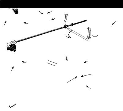
ATTACHING THE HANDLEBAR
 DANGER: To avoid serious injury, the barrier portion of the handlebar must be installed as shown to provide a barrier between operator and the spinning blade.
1.Remove the screw at the rear of the throttle handle.
2.Slide the throttle handle onto the right side of the handlebar (see illustration).
3.Align the screw hole in the throttle handle with the hole in the handlebar.
4.Refit the screw in the hole in the rear of the throttle handle.
5.Screw the screw through the handle and handlebar. Tighten the screw.
6.Fit the mounting components as shown.
2.Position the lower shoulder harness clamp under the shaft and align the upper and lower clamp screw holes. Clamp must be fittle above the arrow on the shaft (see illustration above).
NOTE: Fit throttle wire in groove of lower harness clamp before tightening screws.
3.Insert two screws into the screw holes.
4.Secure shoulder harness clamp by tightening screws with a hex wrench.
SHOULDER HARNESS ADJUSTMENT
At the front of the shoulder harness is an easily accessible quick release. Use the quick release in any emergency situation that requires you to free yourself from the machine and harness.
1.Put on the harness. Adjust the harness for the best working position.
2.Tension the side straps so that the weight is evenly distributed across both shoulders.
7.The handlebar mounting must be fitted between the arrows on the shaft.
8.Tighten the screws with a hex wrench.
ASSEMBLY OF SHOULDER HARNESS
 WARNING: When using a brushcutter, it must always be hooked securely to the shoulder harness. Otherwise, you will be unable to safely control the brushcutter. This can result in injury to yourself or others.
Proper shoulder harness and handlebar adjustments must be made with the engine completely stopped before using unit. A well--adjusted shoulder harness and machine makes work much easier.
ATTACHING SHOULDER HARNESS CLAMP
1.Place the upper shoulder harness clamp over the shaft.
NOTE: It may be necessary to relocate the shoulder harness clamp on the shaft for proper balancing of unit.
SHOULDER HARNESS
ADJUSTMENT
FOR BALANCE
15 cm |
|
|
|
below |
|
|
10 -- 30 cm |
waist |
|
|
above |
|
|
76 cm |
ground |
|
|
|
|
6

3.Pivot shield until bolt passes through hole in bracket.
4.Reinstall nut and tighten securely with wrench (provided).
NOTE: If your unit has a plastic cover over the threads on the threaded shaft, remove the 76 cm covering to expose the threads. Before installing the trimmer head, make sure the dust cup and retaining washer are positioned on the
gearbox as shown below. Bracket
Slot |
Nut |
CONFIGURING YOUR UNIT
You can configure your unit using a cutting head for grass and light weeds, or a weed blade for cutting grass, weeds, and brush up to 1 cm in diameter. To assemble your unit, go to the section for the desired configuration and follow the instructions.
ASSEMBLY INFORMATION - TRIMMER HEAD
TRIMMER
HEAD
NOTE:Remove the blade and metal shield before attaching the plastic shield and trimmer head. To remove blade, align hole in the dust cup with the hole in the side of the gearbox by rotating the blade. Insert a small screwdriver into aligned holes. This will keep the shaft from turning while loosening the blade nut. Remove blade nut by turning clockwise. Remove the screwdriver. Remove both washers and blade. To remove metal shield, loosen and remove the four mounting screws. See ATTACHING THE METAL SHIELD and INSTALLATION OF THE METAL BLADE for illustrations. Be sure to store all parts and instructions for future use.
ATTACHING THE PLASTIC SHIELD AND TRIMMER HEAD
 WARNING: The shield must be properly installed. The shield provides partial protection to the operator and others from the risk of thrown objects, and is equipped with a line limiter blade which cuts excess line to the proper length. The line limiter blade (on underside of shield) is sharp and can cut you.
1.Remove nut from shield.
2.Insert bracket into slot on shield.
Gearbox
Shield
Dust Cup
Retaining Washer
NOTE: Make sure all parts are properly installed as shown in the illustration before installing the trimmer head.
5.Align hole in the dust cup with the hole in the side of the gearbox by rotating the dust cup.
6.Insert a small screwdriver into aligned holes. This will keep the shaft from turning while tightening trimmer head.
Screwdriver
7.While holding the screwdriver in position, thread trimmer head onto the shaft in the direction shown on the decal (counterclockwise). Tighten until secure.
NOTE: The retaining washer must be positioned with the raised section facing toward the gearbox.
ASSEMBLY INFORMATION - WEED BLADE
WEED
BLADE
7

NOTE: Remove the trimmer head and plastic shield before attaching the metal shield and installing the weed blade. To remove the trimmer head, align hole in the dust cup with the hole in the side of the gearbox by rotating the dust cup. Insert a small screwdriver into aligned holes. This will keep the shaft from turning while loosening the trimmer head. Remove the trimmer head by turning clockwise. Remove the screwdriver. To remove the plastic shield, loosen and remove nut. Pivot shield to release bracket from slot. See INSTALLATION OF THE CUTTING HEAD and ATTACHING THE PLASTIC SHIELD for illustrations. Be sure to store all parts and instructions for future use. Never use the trimmer head with the metal blade installed.
ATTACHING THE METAL SHIELD
 WARNING: The metal shield must be properly installed on the tool anytime the tool is used with a blade. Failure to install the shield in the position shown can result in serious injury to the operator. The length of the shield must be aligned with the length of the shaft.
1.Place the metal shield under the gearbox, and align the screw holes.
2.Insert and thread the 4 mounting screws through the holes of the gearbox and the metal shield. Tighten evenly and securely with the hex wrench provided.
INSTALLATION OF THE METAL BLADE
 WARNING: Wear protective gloves when handling or performing maintenance on the blade to avoid injury. The blade is sharp and can cut you even when it is not moving.
 WARNING: Do not use any blades, or
fastening hardware other than the washers and nuts shown in the following illustrations. These parts must be provided by McCulloch and installed as shown below. Failure to use proper parts can cause the blade to fly off and seriously hurt you or others.
NOTE: The dust cup and retaining washer are located on the gearbox shaft and not in the parts bag. All other fasteners mentioned in the following assembly steps are in the parts bag.
1.Remove the retaining washer from the threaded shaft of the gearbox. Leave the dust cup on the shaft.
2.Install the blade and the retaining washer over the threaded shaft.
3.Make sure the raised part of the retaining washer is facing the gearbox and the raised area fits into the hole in the center of the blade.
4.Slide the blade and retaining washer onto the shaft of the gearbox.
5.Place the cupped washer onto the shaft. Make sure the cupped side of the washer is toward the blade.
6.Install the blade nut by threading onto the shaft counterclockwise.
Threaded Shaft
Blade
Retaining
Washer
Cupped
Washer
Nut
NOTE: Make sure all parts are in place as illustrated, and the blade is sandwiched between the dust cup and the retaining washer. There should be no space between the blade and the dust cup or the retaining washer.
7.Align hole in dust cup with hole in side of gearbox by rotating the blade.
8.Insert a small screwdriver into aligned holes. This will keep the shaft from turning while tightening the blade nut.
Screwdriver
9.Tighten blade nut firmly with a wrench while holding screwdriver in position.
10.Remove the screwdriver.
11.Turn blade by hand. If the blade binds against the shield, or appears to be uneven, the blade is not centered, and you must reinstall.
NOTE: To remove blade, insert screwdriver into aligned holes. Unthread the nut and remove parts. Be sure to store parts and instructions for future use.
8

OPERATION
 WARNING: Be sure to read the fuel
information in the safety rules before you begin. If you do not understand the safety rules, do not attempt to fuel your unit. Contact an authorized service dealer.
FUELING ENGINE
 WARNING: Remove fuel cap slowly when refueling.
This engine is certified to operate on unleaded petrol. Before operation, petrol must be mixed with a good quality 2-cycle air-cooled engine oil. We recommend McCulloch brand oil mixed at a ratio of 40:1 (2.5%). A 40:1 ratio is obtained by mixing 5 liters of unleaded petrol with 0,125 liter of oil. DO NOT USE automotive oil or boat oil. These oils will cause engine damage. When mixing fuel, follow instructions printed on oil container. Once oil is added to petrol, shake container momentarily to assure that the fuel is thoroughly mixed. Always read and follow the safety rules relating to fuel before fueling your unit.
IMPORTANT
Experience indicates that alcohol blended fuels (called gasohol or using ethanol or methanol) can attract moisture which leads to separation and formation of acids during storage. Acidic gas can damage the fuel system of an engine while in storage. To avoid engine problems, empty the fuel system before storage for 30 days or longer. Drain the gas tank, start the engine and let it run until the fuel lines and carburetor are empty. Use fresh fuel next season. Never use engine or carburetor cleaner products in the fuel tank or permanent damage may occur.
HOW TO STOP YOUR UNIT
S To stop the engine, move the ON/STOP switch to the STOP position.
ON/STOP Switch
HOW TO START YOUR UNIT
 WARNING: Avoid any contact with the muffler. A hot muffler can cause serious burns.
STARTING A COLD ENGINE (or a warm engine after running out of fuel)
Starting position
Starter Handle
Start Lever
Primer Bulb  Muffler
NOTE: The throttle lock--out is designed to prevent unintentional use of the throttle trigger. The lock--out must be pressed with the palm of your hand as you grip the throttle handle before the trigger can be used. DO NOT squeeze the throttle trigger until the engine has started and runs.
1.Set unit on a flat surface.
2.Move ON/STOP switch to the ON position.
3.Slowly press the primer bulb 6 times.
4.Move the start lever to the START position.
5.Pull starter rope handle sharply until engine starts and runs.
6.Allow unit to run for 10--15 seconds, then fully squeeze the throttle trigger to disengage the starting system.
STARTING A WARM ENGINE
1.Move ON/STOP switch to the ON position.
2.Squeeze and hold the throttle trigger. Keep throttle trigger fully squeezed until engine runs smoothly.
3.Pull starter rope sharply while squeezing throttle trigger until engine runs.
NOTE: Normally, the warm starting procedure can be used within 5 -- 10 minutes after the unit is turned STOP. If the unit sits for more than 10 minutes without being run, it will be necessary to start the unit by following the steps under STARTING A COLD ENGINE or following the starting instruction steps shown on the unit.
STARTING A FLOODED ENGINE
Flooded engines can be started by placing the ON/STOP switch in the ON position. Move the start lever to the RUN position and fully squeeze throttle trigger. Pull the starter handle repeatedly while squeezing throttle trigger until engine starts and runs. This could require pulling the starter handle many times,
9

depending on how badly the unit is flooded. If the unit still doesn’t start, refer to the TROUBLESHOOTING TABLE.
OPERATING POSITION
ALWAYS |
Safety Helmet |
Hearing 
Protection
Heavy,
Long Pants
Boots
Cut from your left to your right.
When operating unit, clip shoulder harness onto clamp, stand as shown andcheck for the following:
SWear eye protection and heavy clothing.
SExtend your left arm and hold handlebar grip with your left hand.
SHold throttle grip with your right hand with finger on throttle trigger.
SKeep unit below waist level.
SMaintain full weight of tool on both shoulders.
SWithout bending over, keep the blade or trimmer head near and parallel to the ground and not crowded into material being cut.
OPERATING INSTRUCTIONS FOR USE WITH TRIMMER HEAD
 WARNING: Always wear eye protec-
tion. Never lean over the trimmer head. Rocks or debris can ricochet or be thrown into eyes and face and cause blindness or other serious injury.
Before trimming, bring engine to a speed sufficient to cut material to be trimmed.
Do not run the engine at a higher speed than necessary. The cutting line will cut efficiently when the engine is run at less than full throttle. At lower speeds, there is less engine noise and vibration. The cutting line will last longer and will be less likely to “weld” onto the spool.
Always release the throttle trigger and allow the engine to return to idle speed when not cutting.
To stop engine:
SRelease the throttle trigger.
SMove the ON/STOP switch to the STOP position.
TRIMMER LINE ADVANCE
Advance line by tapping the bottom of the cutting head lightly on the ground while engine is running at full speed. The metal line limiter blade attached to the guard will cut the line to the proper length.
 WARNING: Use only 2,4 mmdiameter line. Other sizes of line will not advanceproperly
and can cause serious injury. Do not use other materials such as wire, string, rope, etc. Wire can break off during cutting and become a dangerous missile that can cause serious injury.
CUTTING METHODS
 WARNING: Use minimum speed and
do not crowd the line when cutting around hard objects (rock, gravel, fence posts, etc.), whichcandamage the trimmer head, become entangled in the line, or be thrown causing a serious hazard.
SThe tip of the line does the cutting. You will achieve the best performance and minimum line wear by not crowding the line into the cutting area. The right and wrong ways are shown below.
Tip of line does |
Line crowded into |
the |
|
Right |
Wrong |
SThe line will easily remove grass and weeds from around walls, fences, trees and flower beds, but it also can cut the tender bark of trees or shrubs and scar fences.
SFor trimming or scalping, use less than full throttle to increaseline life and decreasehead wear, especially:
S During light duty cutting.
S Near objects around which the line can
wrap such as small posts, trees or fence wire.
S For mowing or sweeping, use full throttle for a good clean job.
TRIMMING -- Hold the bottom of the trimmer head about 8 cm above the ground and at an angle. Allow only the tip of the line to make contact. Do not force trimmer line into work area.
Trimming
80mm above ground
SCALPING -- The scalping technique removes unwanted vegetation down to the ground. Hold the bottom of the trimmer head about 8 cm above the ground and at an angle. Allow the tip of the line to strike the ground around trees, posts, monuments, etc. This technique increases line wear.
10
MOWING -- Your trimmer is ideal for mowing in places conventional lawn mowers cannot reach. In the mowing position, keep the line parallel to the ground. Avoid pressing the head into the ground as this can scalp the ground and damage the tool.
Mowing
SWEEPING -- The fanning action of the rotating line can be used to blow away loose debris from an area. Keep the line parallel to and above the area surface and swing the tool from side to side.
OPERATING INSTRUCTIONS FOR USE WITH WEED BLADE
SBlade Thrust is a reaction that only occurs when using a bladed unit. This reaction can cause serious injury such as amputation. Carefully study this section. It is important that you understand what causes blade thrust, how you can reduce the chance of its occurring, and how you can remain in control of unit if blade thrust occurs.
SWHAT CAUSES BLADE THRUST -- Blade Thrust can occur when the spinning blade contacts an object that it does not cut. This contact causes the blade to stop for an instant and then suddenly move or “thrust” away from the object that was hit. The “thrusting” reaction can be violent enough to cause the operator to be propelled in any direction and lose control of the unit. The uncontrolled unit
can cause serious injury if the blade contacts the operator or others.
S WHEN BLADE THRUST OCCURS --
Blade Thrust can occur without warning if the blade snags, stalls, or binds. This is more likely to occur in areas where it is difficult to see the material being cut. By using the unit properly, the occurrence of blade thrust will be reduced and the operator will be less likely to lose control.
SCut only grass, weeds, and woody brush up to 1 cm in diameter with the weed blade. Do not let the blade contact material it cannot cut such as stumps, rocks, fences, metal, etc., or clusters of hard, woody brush having a diameter greater than 1 cm.
SKeep the blade sharp. A dull blade is more likely to snag and thrust.
SCut only at full throttle. The blade will have maximum cutting power and is less likely to bind or stall.
S“Feed” the blade deliberately and not too rapidly. The blade can thrust away if it is fed too rapidly.
SCut only from your left to your right. Cutting on right side of the shield will throw debris away from the operator.
SUse the shoulder harness and keep a firm grip on the unit with both hands. A properly adjusted shoulder harness will support the weight of the unit, freeing your arms and hands to control and guide the cutting motion.
SKeep feet comfortably spread apart and braced for a possible sudden, rapid thrust of unit. Do not overreach. Keep firm footing and balance.
SKeep blade below waist level; it will be easier to maintain control of unit.
SDo not raise the engine above your waist as the blade can come dangerously close to your body.
SDo not swing unit with such force that you are in danger of losing your balance.
Bring the engine to cutting speed before entering the material to be cut. If the blade does not turn when you squeeze the throttle trigger, make sure shaft is fully inserted into the engine.
Always release the throttle trigger and allow engine to return to idle speed when not cutting. The blade should not turn while the engine is running at idle. If the blade turns at idle, do not use your unit. Refer to the CARBURETOR ADJUSTMENT section or contact your authorized service dealer.
SMaintain good firm footing while using the unit. Do this by planting feet firmly in a comfortable apart position.
11

SCut while swinging the upper part of your body from left to right.
SAs you move forward to the next area to cut, be sure to maintain your balance and footing.
RECOMMENDED CUTTING POSITION 2 o’clock
Cut using the 2
o’clock to 4 o’clock
position of the 4 o’clock blade
 WARNING: The operator or others
must not try to clear away cut material withthe engine running or the blade turning to avoid serious injury. Stop engine and blade before removing materials wrapped around blade or shaft.
MAINTENANCE
The life span of the machine can be reduced and the risk of accidents can increase if machine maintenance is not carried out correctly and if service and/or repairs are not carried out professionally. If you need further information, please contact your nearest authorised service dealer.
 WARNING: Disconnect the spark
plug before performing maintenance except for carburetor adjustments.
CHECK FOR LOOSE FASTENERS AND PARTS
SSpark Plug Boot
SAir Filter
SHousing Screws
SHandlebar Screws
SDebris Shield
CHECK FOR DAMAGED OR WORN PARTS
Contact an authorized service dealer for replacement of damaged or worn parts.
SON/STOP Switch -- Ensure ON/STOP switch functions properly by moving the switch tothe STOP position. Make sure engine stops; then restart engine and continue.
SFuel Tank -- Discontinue use of unit if fuel tank shows signs of damage or leaks.
SDebris Shield -- Discontinue use of unit if debris shield is damaged.
INSPECT AND CLEAN UNIT AND LABELS
S After each use, inspect complete unit for loose or damaged parts. Clean the unit and labels using a damp cloth with a mild detergent.
S Wipe off unit with a clean dry cloth.
CLEAN AIR FILTER
A dirty air filter decreases engine performance and increases fuel consumption and harmful emissions. Always clean after every 5 hours of operation.
1.Clean the cover and the area around it to keep dirt from falling into the carburetor chamber when the cover is removed.
2.Remove parts as illustrated.
NOTE: Do not clean filter in petrol or other flammablesolvent to avoid creatinga fire hazard or producing harmful evaporative emissions.
3.Wash the filter in soap and water.
4.Allow filter to dry.
5.Replace parts.
Air Filter
Button
Air Filter
Cover
REPLACE SPARK PLUG
Replace the spark plug each year to ensure the engine starts easier and runs better. Set spark plug gap at 0,6 mm. Ignition timing is fixed and nonadjustable.
1.Twist, then pull off spark plug boot.
2.Remove spark plug from cylinder and discard.
3.Replace with Champion RCJ-6Y spark plug and tighten securely with a 19 mm socket wrench.
4.Reinstall the spark plug boot.
12

SERVICE AND ADJUSTMENTS
REPLACING THE LINE
1.Press the tabs on the side of the trimmer head and remove cover and spool.
Cover
 Tab
Tab
Button
2.Remove any remaining line.
3.Clean dirt and debris from all parts. Replace spool if it is worn or damaged.
4.Replace with a pre-wound spool, or replace line using a 4,5 meters length of 2,4 mm diameter McCulloch brand line.
5.When installing new line on an existing spool, hold the spool as shown in the illustration below.
6.Bend the line at the midpoint and insert the bend into the slot in the center rim of the spool. Ensure line snaps into position in the slot.
 Slot
Slot
Spool
7.With your finger between the lines, wrap the lines evenly and firmly around the spool in a clockwise direction.
8.Position the lines in the guide slots.
Guide Slot
Guide
Slot
9.Insert the ends of the lines through exit holes in the sides of the cover.
10.Place the spool in the cover.
Spool
Cover
11.Make sure the lines are not caught between the rim of the spool and the wall of the cover.
12.Reinstall the spool and cover onto the trimmer head. Push until cover snaps into place.
BLADE REPLACEMENT
Refer to the ASSEMBLY section for blade replacement instructions and illustrations.
CARBURETOR ADJUSTMENT
 WARNING: Keep others away when
making idle speed adjustments. The trimmer head will be spinning during most of this procedure. Wear your protective equipment and observe all safety precautions. After making adjustments, the trimmer head must not move/spin at idle speed.
The carburetor has been carefully set at the factory. Adjustments may be necessary if you notice any of the following conditions:
S Engine will not idle when the throttle is released.
S The trimmer head moves/spins at idle speed. Make adjustments with the unit supported so the cutting attachment is off the ground and will not make contact with any object. Hold the unit by hand while running and making adjustments. Keep all parts of your body away from the cutting attachment and muffler.
Idle Speed Adjustment
Allow engine to idle. Adjust speed until engine runs without trimmer head moving or spinning (idle speed too fast) or engine stalling (idle speed too slow).
S Turn idle speed screw clockwise to increase engine speed if engine stalls or dies.
STurn idle speed screw counterclockwise to decrease engine speed if trimmer head moves or spins at idle speed.
 WARNING: Recheck the idle speed
after each adjustment. The trimmer head must not move or spin at idle speed to avoid serious injury to the operator or others.
13

If you require further assistance or are unsure about performing this procedure, contact an authorized service dealer.
Air Filter
Cover
Idle Speed 
Screw
STORAGE
 WARNING: Perform the following steps after each use:
SAllow engine to cool before storing or transporting.
SStore unit and fuel in a well ventilated area where fuel vapors cannot reach sparks or open flames from water heaters, electric motors or switches, furnaces, etc.
SEmpty fuel tank before storing or transporting the unit.
SStore unit and fuel well out of the reach of children.
SStore unit with all guards in place. Position unit so that any sharp object cannot accidentally cause injury.
SEASONAL STORAGE
Prepare unit for storage at end of season or if it will not be used for 30 days or more.
If your unit is to be stored for a period of time:
SClean the entire unit before lengthy storage.
SStore in a clean dry area.
SLightly oil external metal surfaces.
ENGINE
SRemove spark plug and pour 1 teaspoon of 40:1, 2-cycle engine oil (air cooled) through the spark plug opening. Slowly pull the starter rope 8 to 10 times to distribute oil.
SReplace spark plug with new one of recommended type and heat range.
SClean air filter.
SCheck entire unit for loose screws, nuts, and bolts. Replace any damaged, broken, or worn parts.
SAt the beginning of the next season, use only fresh fuel having the proper petrol to oil ratio.
OTHER
S Do not store petrol from one season to another.
S Replace your petrol can if it starts to rust.
14
TROUBLESHOOTING TABLE
 WARNING: Always stop unit and disconnect spark plug before performing all of the recommended remedies below except remedies that require operation of the unit.
TROUBLE |
CAUSE |
REMEDY |
||
Engine will not |
1. ON/STOP switch in STOP |
1. |
Move ON/STOP switch to ON |
|
start. |
|
position. |
|
position. |
|
2. Engine flooded. |
2. |
See “Starting a Flooded Engine” in |
|
|
3. Fuel tank empty. |
|
Operation Section. |
|
|
3. |
Fill tank with correct fuel mixture. |
||
|
4. Spark plug not firing. |
4. |
Install new spark plug. |
|
|
5. Fuel not reaching |
5. |
Check for dirty fuel filter; replace. |
|
|
|
carburetor. |
|
Check for kinked or split fuel line; |
|
6. Carburetor requires |
|
repair or replace. |
|
|
6. |
Contact an authorized service dealer. |
||
|
|
adjustment. |
|
|
|
|
|
|
|
Engine will |
1. Carburetor requires |
1. |
See “Carburetor Adjustment” in |
|
not idle |
|
adjustment. |
|
Service and Adjustments Section. |
properly. |
2. Crankshaft seals worn. |
2. |
Contact an authorized service dealer. |
|
|
3. Compression low. |
3. |
Contact an authorized service dealer. |
|
Engine will not |
1. |
Air filter dirty. |
1. Clean or replace air filter. |
|
accelerate, |
2. Spark plug fouled. |
2. Clean or replace plug |
||
lacks power, |
3. |
Carburetor requires |
|
and regap. |
or dies under |
3. Contact an authorized service dealer. |
|||
a load. |
4. |
adjustment. |
4. Contact an authorized service dealer. |
|
|
Carbon build-up on |
|||
|
|
muffler outlet screen. |
|
|
|
5. |
Compression low. |
5. Contact an authorized service dealer. |
|
Engine |
1. |
Choke partially on. |
1. |
Adjust choke. |
smokes |
2. |
Fuel mixture incorrect. |
2. |
Empty fuel tank and refill with |
excessively. |
|
|
|
correct fuel mixture. |
|
3. |
Air filter dirty. |
3. |
Clean or replace air filter. |
|
4. |
Carburetor requires |
4. |
Contact an authorized service dealer. |
|
|
adjustment. |
|
|
Engine runs |
1. Fuel mixture incorrect. |
1. Empty fuel tank and refill with |
||
hot. |
|
|
|
correct fuel mixture. |
|
2. Spark plug incorrect. |
2. Replace with correct spark plug. |
||
|
3. Carburetor requires |
3. Contact an authorized service dealer. |
||
|
|
adjustment. |
|
|
|
4. Carbon build-up on |
4. Contact an authorized service dealer. |
||
|
|
muffler outlet screen. |
|
|
15

DECLARATION OF CONFORMITY
EC Declaration of Conformity (Only applies to Europe)
We, Husqvarna AB, SE--561 82 Huskvarna, Sweden, Tel: +46--36--146000, as authorised representative in the Community, declare that the brushcutter model McCulloch M B325 CB from serial numbers 2009--031N00001 and onwards (the year is clearly stated on the rating plate, followed by the serial number), comply with the requirements of the COUNCIL’S DIRECTIVES:
of 22 June 1998 “relating to machinery” 98/37/EC, annex IIA;
of 15 December 2004 “relating to electromagnetic compatibility” 2004/108/EC, and applicable supplements; and
of 8 May 2000 “relating to the noise emissions in the environment” in accordance with Annex V of 2000/14/EC. The measured sound power is 112,6 dB(A), the guaranteed sound power is 117,0 dB(A). The cutting width is 43 cm.
The following standards have been applied: EN12100--1:2003, EN 12100--2:2003, EN ISO 11806:1997 and CISPR 12:2005.
SMP, The Swedish Machinery Testing Institute, Fyrisborgsgatan 3 S--754 50 Uppsala, Sweden, has carried out voluntary type approval. The certificate(s) are numbered:
SEC/08/1231.
09--1--31
Ronnie E. Goldman, Director of Engineering
Handheld Consumer Products
16

TECHNICAL DATA SHEET
MODEL: M B325 CB |
BLADE |
TRIMMER |
ENGINE |
|
|
Displacement, cm3 |
32 |
32 |
Maximum engine power, measured in |
|
|
accordance with ISO 8893, kW |
0,7 |
0,7 |
ENGINE ROTATIONAL SPEEDS |
|
|
At maximum engine power, rpm |
7000 |
7000 |
Maximum rotational frequency of the spindle |
10000 |
10000 |
Engine speed at recommended maximum |
|
|
spindle rotational frequency |
7400 |
7400 |
Recommended speed idling, rpm |
3000 |
3000 |
FUEL AND LUBRICATION SYSTEM |
|
|
Fuel tank volume capacity, cm3 |
325 |
325 |
Fuel consumption at maximum engine power, |
|
|
measured in accordance with ISO 8893, g/h |
399 |
399 |
Specified fuel consumption at max. engine power, |
|
|
measured in accordance with ISO 8893, g/kWh |
435 |
435 |
WEIGHT |
|
|
Without cutting attachment or shield, empty tank, kg |
5,9 |
5,9 |
CUTTING ATTACHMENT |
|
|
Weed blade, part number |
#530055892 Opt. |
|
Cutting head assembly, part number |
Opt. |
#537419202 |
NOISE LEVELS (Octave Band Analysis 100-10000hz 1/3 Octave) |
|
|
SOUND PRESSURE LEVELS measured in accordance with ISO 22868 |
|
|
Idling, dB(A) |
80,7 |
80,7 |
Racing, dB(A) |
100,5 |
102,7 |
SOUND POWER LEVELS in accordance with ISO 22868 |
|
|
Sound power level, measured dB(A) |
112,6 |
112,6 |
Sound power level, guaranteed LWA dB(A) |
117,0 |
117,0 |
VIBRATION LEVELS measured in accordance with ISO 22867 |
|
|
LEFT HANDLE |
|
|
Idling, m/s2 |
4,6 |
4,3 |
Racing, m/s2 |
14,9 |
10,9 |
RIGHT HANDLE |
|
|
Idling, m/s2 |
5,1 |
4,6 |
Racing, m/s2 |
13,4 |
4,4 |
17
IDENTIFICACIÓN DE LOS COMPONENTES
3  14
14
7
4
|
9 |
|
|
|
|
11 |
|
|
|
|
|
|
18 |
|
|
22 |
|
|
|
|
|
|
|
|
|
20 |
|
17 |
|
|
|
|
19 |
|
|
23 |
|
|
|
|
21 |
|
|
|
1. |
Depósito de combustible |
13. |
Cerradura del acelerador |
|
2. |
Manillar |
14. |
Botón de aceleración de arranque |
|
3. |
Interruptor ON/STOP |
15. |
Cuerda de arranque |
|
4. |
Sujetador del cable del acelerador |
16. |
Tapa del tanque de combustible |
|
5. |
Abrazadera del arnés |
17. |
Bombeador |
|
6. |
Arnés |
18. |
Palanca del arrancador |
|
7. |
Cabezal de corte |
19. |
Silenciador |
|
8. |
Cuchilla de línea |
20. |
Llave |
|
9. |
Protector |
21. |
Llave hexagonal |
|
10. |
Eje |
22. |
Protector de transporte |
|
11. |
Cuchilla |
23. |
Manual de instrucciones |
|
12. |
Gatillo acelerador |
|
|
|
18

IDENTIFICACIÓN DE SÍMBOLOS
A. |
|
D. |
|
F. |
|
I. |
|
L. |
|
B. |
|
|
E. |
|
G. |
|
J. |
|
|
|
|
|
|
|
|
||||
|
|
|
|
|
|
||||
C. |
|
|
|
|
H. |
|
K. |
|
|
|
|
|
|
|
|
|
|||
|
|
|
|
|
|
|
|||
|
|
|
|
|
|
|
|
|
|
A. ¡ADVERTENCIA! Este cortabordes puede ser peligroso. Su uso imprudente o inadecuado puede ocasionar lesiones graves e incluso mortales.
B.Antes de usar el cortabordes, lea atentamente este manual de instrucciones y asegúrese de haberlo comprendido.
C.Utilice siempre:
Protectores acústicos, anteojos de seguridad, casco de seguridad, botas y guantes.
D.¡PELIGRO! La cuchilla puede rebotar violentamente en materiales que no puede cortar. Los rebotes de la cuchilla pueden causar la amputación de brazos o piernas. Mantenga a personas y animales lejos de la herramienta (15 metros).
E.¡ADVERTENCIA! El hilo cortador puede despedir objetos violentamente.
Esto puede ocasionarle ceguera o lesiones. Utilice siempre una protección para los ojos.
F.Durante el trabajo, el operador debe asegurarse de que ninguna otra persona se aproxime a menos de un radio de 15 metros de la máquina. Cuando se trabaje en equipo, los operadores deberán mantener entre sí una distancia de seguridad de al menos 15 metros.
G.Utilice gasolina sin plomo o de gran calidad y aceite para motores de dos tiempos mezclado en proporción al 2,5%.
H.El mango de apoyo debe colocarse siempre por debajo de la flecha.
I.Interruptor ON/STOP (marcha y parada) del motor
J.Nivel de potencia acústica garantizada (relacionada con Directiva 2000/14/CE)
K.Frecuencia de rotación máxima del eje, en rpm
L.Nivel de presión acústica en 7,5 metros
REGLAS DE SEGURIDAD
 ADVERTENCIA: Al usar cualquier herramienta de fuerza de jardinería, deberán observarse precauciones básicas de seguirdad en todo momento para reducir el riesgo de incendio y graves heridas. Lea y cumpla con todas las instrucciones.
 PELIGRO: ¡Esta herramienta motorizada puede ser peligrosa! Puede ocasionar lesiones graves, incluso la amputación o la ceguera, tanto al operador como a otras personas. Las advertencias e instrucciones de seguridad contenidas en este manual deben cumplirse en todo momento para garantizar un nivel de seguridad y efectividad razonable durante la utilización del aparato. El operador es responsable del cumplimiento de las advertencias e instrucciones indicadas en este manual y en el aparato. Antes de ensamblar y utilizar el aparato, lea íntegramente el manual de instrucciones. Limite el
uso de este aparato a personas que previamente hayan leído y comprendido, y posteriormente cumplan, las advertencias e instrucciones indicadas en este manual y en el aparato. Nunca permita que este aparato sea utilizado por niños.
MANUAL DE |
INFORMACION DE |
INSTRUCCIONES |
SEGURIDAD DEL |
|
APARATO |
 PELIGRO: La cuchilla puede rebotar violentamente en materiales que no puede cortar. Los rebotes de la cuchilla pueden causar la amputación de brazos o piernas. Mantenga a personas y animales lejos de la herramienta (15 metros).
19

 ADVERTENCIA: La cuchilla y la línea de corte arroja objetos violentamente. Usted, al igual que otras personas, puede quedar ciego o herido. Use anteojos de seguridad y protección en las piernas.
 ADVERTENCIA: Zona de peligro de objetos despedidos. La cuchilla y la línea de corte arroja objetos violentamente. Esto puede ocasionar ceguera o lesiones a otros. Mantenga a personas y animales lejos de la herramienta 15 metros.
de peligro
 ADVERTENCIA: No utilice el cabezal de corte como dispositivo de sujeción de la cuchilla.
 ADVERTENCIA: La cuchilla sigue girando incluso después de soltar el acelerador o de apagar el motor. Incluso cuando está girando libremente, la cuchilla puede despedir objetos o causar cortes profundos si se toca accidentalmente. Detenga la cuchilla poniendo en contacto el lado derecho de la misma con material ya cortado.
Para detener la cuchilla cuando gire libremente, póngala en contacto con material previamente cortado.
SEGURIDAD DEL USUARIO
SVistase apropiadamente. Siempre use anteojos de seguridad o similar protección para los ojos cuando use o dé mantenimiento a este aparato (anteojos de seguridad están disponibles). La protección para los ojos se debe marcar con Z87.
SEs obligatorio usar casco si van a desbrozarse ramas a una altura superior a 2 metros.
SSiempre utilize mascarilla para la cara o mascarilla a prueba de polvo si se va a trabajar en condiciones donde hay polvo.
SSiempre utilize pantalones pesados y largos, mangas largas, botas y guantes. Se recomienda el uso de pantorrilleras de seguridad.
SSiempre utilize protección para los pies. No trabaje descalzo ni en sandalias. Evite la línea/cuchilla girante.
SMantenga el cabello por encima de los hombros, atándolo para tal efecto si es necesario. No use ropa suelta ni ropa con corbatas, tiras, borlas, etc. que cuelgan libremente. Pueden enredarse en las piezas en movimiento.
SSi está completament tapado, estará más protegido de los escombros y pedazos de plantas tóxicos arrojados por la línea girante.
SManténgase alerta. No haga uso del aparato estando cansado, enfermo, trastornado o bajo la influencia del alcohol, de drogas o de remedios. Vigile bien lo que está haciendo; use del sentido común.
SUse protección para los oídos. La exposición larga o continua a los altos niveles de ruidos puede causar el daño permanente de audición.
SNunca ponga el aparato en marcha ni lo deje en marcha dentro de un recinto cerrado. Respirar los vapores del combustible lo puede matar.
SMantenga las manijas libres de aceite y de combustible.
SSiempre que trabaje con cuchillas, utilice el manillar y una arnés correctamente ajustada (vea MONTAJE).
SEGURIDAD DEL APARATO Y EN EL MANTENIMIENTO
 ADVERTENCIA: Apague el aparato y desconecte la bujía antes de hacer cualquier mantenimiento menos los ajustes al carburador. S Deseche la cuchillas dobladas, dentadas, partidas, rotas o deterioradas de algún modo. Antes de utilizar el aparato, sustituya las piezas del cabezal de corte que estén parti-
das, rotas o deterioradas de algún modo.
SHaga el mantenimiento del aparato de acuerdo a los procedimientos recomendados. Man-
20
tenga la cuchilla afilada. Mantenga la línea de corte el largo aprodiado.
SUse solamente línea de diámetro 3 mm de pulgada) de la marca McCulloch. Nunca use alambre, soga, hilo, etc.
SInstale la protector requerida antes de usar su aparato. Use la protector de metal para todo el uso con cuchillas de metal. Use la protector de plástico para todo el uso con línea de corte.
SUse solamente la cuchilla o el cabezal de corte que aquí se especificada. Asegúrese queestén instalados apropiadamente y ajustados con seguridad.
SNunca ponga en marcha el motor con el cobertor del embrague desmontado. El embrague podría desprenderse y causar graves lesiones.
SAsegúrese que el cuchilla o el cabezal de corte paren de girar cuando el motor se encuentra en marcha lenta.
SRealice los ajustes del carburador con la parte inferior apoyada en alto para impedir que la cuchilla o el hilo podador entren en contacto con algún objeto. Sujete el aparato con las manos, sin utilizar un arnés.
SCuando realice ajustes en el carburador, mantenga alejadas del lugar a otras personas.
SUtilice exclusivamente los accesorios y recambios recomendados por McCulloch.
STodo servicio y mantinimiento no explicado en este manual deberá ser efectuado por un distribuidor autorizado del servicio.
SEGURIDAD CON EL COMBUSTIBLE
SMezcle y vierta el combustible al aire libre.
SManténgalo alejado de las chispas y de las llamas.
SUse recipiente aprobado para el combustible.
SNo fume ni permita que se fume cerca del combustible ni del aparato ni mientras éste esté en uso.
SEvite derramar el combustible o el aceite. Limpie todo el combustible derramado.
SAléjese a por lo menos 3 metros del lugar de abastecimiento antes de poner en marcha el motor.
SAntes de guarder el aparato, vacíe el depósito de combustible. Arranque el motor y déjelo en marcha hasta que se detenga con el fin de agotar el combustible que pueda quedar en el carburador.
SPare el motor y permita que se enfríe el aparato antes de retirar la tapa del tanque.
SAlmacéne siempre combustible en un recipiente aprobado para los líquidos inflamables.
SEGURIDAD AL CORTAR
 ADVERTENCIA: Antes de cada uso, inspeccione la zona de trabajo. Retire todos los objetos (rocas, cristales rotos, clavos, cables, hilos, etc.) que puedan ser despedidos o quedar enredados en la cuchilla o en el cabezal de corte.
SMantenga alejados del lugar de trabajo 15 metros a otras personas, ya sean niños, acompañantes o ayudantes, y a animales. Detenga el motor tan pronto como alguien se le aproxime.
SMantenga siempre el motor junto al lado dere-
cho de su cuerpo.
SSujete firmemente el aparato con ambas manos.
SPise con seguridad y mantenga el equilibrio en todo momento. No estire el cuerpo en exceso.
SMantenga la cuchilla o cabezal de corte por debajo de la cintura. No levante el motor por encima de su cintura.
SMientras el motor esté en marcha, mantenga todas las partes de su cuerpo alejadas de la cuchilla o del cabezal de corte, y del silenciador. Un silenciador caliente podría provocar quemaduras de gravedad si se toca.
SCorte siempre de izquierda a derecha. Si se corta con la línea del lado derecho del protector, los escombros volarán en sentido opuesto al usuario.
SUse el aparato únicamente de día o en luz artificial fuerte.
SUtilice el aparato solamente para las tareas explicadas en este manual.
TRANSPORTE Y ALMACENAMIENTO
SAntes de almacenar o transportar el aparato en un vehículo, deje enfriar el motor y sujete bien el aparato.
SAntes de guardar o transportar el aparato, vacíe el depósito de combustible. Arranque el motor y déjelo en marcha hasta que se detenga con el fin de agotar el combustible que pueda quedar en el carburador.
SGuarde el aparato y el combustible en un lugar donde los vapores emanados del combustible no puedan entrar en contacto con chispas ni llamas procedentes de calentadores de agua, motores o interruptores eléctricos, hornos, etc.
SGuarde el aparato de modo que la cuchilla o el limitador de hilo no puedan ocasionar lesiones accidentalmente. Este aparato puede colgarse por la barra.
SAntes de guardar o transportar el aparato, cubra la cuchilla con el protector de transporte.
SGuarde el aparato fuera del alcance de los niños.
AVISO SPECIAL: El estar expuesto a las vibraciones a través del uso prolongado de herramientas de fuerza a gasolina puede cuasar daños a los vasos sanguíneos o a los nervios de los dedos, las manos y las coyunturas en aquellas personas que tienen propensidad a los trastornos de la circulación o a las hinchazones anormales. El uso prolongado en tiempo frío ha sido asociado con daños a los vasos snaguíneos de personas que por otra parte se encuentran en perfecto estado de salud. Si ocurren síntomas tales como el entumecimiento, el dolor, la falta de fuerza, los cambios en el color o la textura de la piel o falta de sentido en los dedos, las manos o las coyunturas, deje de usar esta máquina inmediatamente y procure atención médica. Los sistemas de anti--vibración no garantizan que se eviten tales problemes.
Los usuarios que hacen uso continuo y prolongando de las herramientas de fuerza deben fiscalizar atentamente su estado físico y el estado del aparato.
21

MONTAJE
CONTENIDO DE LA CAJA
Use la siguiente lista para verificar que todas la piezas hayan sido incluídas:
SCortadora de malezas
SProtector metálica
STornillos de la montaje (4)
SCuchilla
SArandela abombada
STuerca grande para la instalación de la cuchilla
SCabezal de corte
SProtector plástica
STuerca (atornillada en la protector)
SManillar
STapa del soporte
STornillos para la tapa del soporte (2)
SAbrazadera superior del arnés
SAbrazadera inferior del arnés
STornillos de abrazadera del arnés (2)
SArnés
SLlave hexagonal
SLlave
SProtector de transporte
SSujetador del cable del acelerador
 ADVERTENCIA: Siempre apague el aparato y desconecte la bujía antes de hacer cualquiera de las procedimientos de la montaje.
 ADVERTENCIA: Si recibió el aparato ya armado, repita todos los pasos para asegurar que el mismo se encuentre correctamente armado y que todos los fijadores se encuentren bien ajustados.
Examine las piezas para verificar que no haya daños. No use piezas dañadas.
Es normal escuchar que el filtro de combustible golpetee en el tanque vacío.
Es normal encontrar residuos de aceite o de gasolina en el silenciador, debido a los ajustes al carburador y a las pruebas efectuadas por el fabricante.
HERRAMIENTAS NECESARIAS
SLlave hexagonale (incluidas)
SLlave ajustable
SDestornillador phillips
INSTALACION DEL MANILLAR
 PELIGRO: Para evitar graves heridas, la porción del manillar en forma de barrera debe ser ajustada y seguir instalada según se indica con el fin de mantener la distancia entre el operador y la cuchilla durante el giro de ésta.
1.Afloje y quite el tornillo en la parte posterior del acelerador.
2.Deslice el acelerador en el lado derecho del manillar (vea la ilustración).
3.Haga coincidir el orificio para el tornillo de sujeción del acelerador con el orficio del manillar.
4.Vuelva a colocar el tornillo en el orificio en la parte posterior del acelerador.
5.Enrosque el tornillo a través del acelerador y el manillar. Apriete.
6.Coloque las piezas de sujeción como indica la ilustración.
7.La sujeción del mango debe montarse entre las marcas con flechas en el tubo.
8.Apriete los tornillos con la llave hexagonal.
MONTAJE DEL ARNÉS
 ADVERTENCIA: Al trabajar con una desbrozadora, ésta siempre debe engancharse en el arnés. De lo contrario, Ud. no puede maniobrar la desbrozadora de manera segura y esto puede ocasionarle daños a Ud. o a terceros.
Antes de hacer algun ajuste de la arnés o el manillar, es imprescindible que el motor este completamente detenido. Un arnés y una máquina correctamente ajustados facilitan considerablemente el trabajo.
MONTAJE DE LA ABRAZADERA DEL ARNÉS
1.Coloque la abrazadera superior del arnés sobre el eje
2.Coloque la abrazadera inferior del arnés debajo del eje. Alinee los huecos del tornillo de la abrazadera superior y la abrazadera inferior. La abrazadera debe montar sobre la marca con flecha en el tubo (vea la ilus-
tración).
NOTA: Coloque el alambre del cable del acelerador en el ranura de la abrazadera inferior del arnés antes de apretar los tornillos.
3.Inserte dos tornillos en los huecos para tornillos.
4.Apriete la abrazadera del arnés apretando los tornillos con la llave hexagonal.
22
 Loading...