

Mazda RX-7 1989 Service Highlights
RX-7
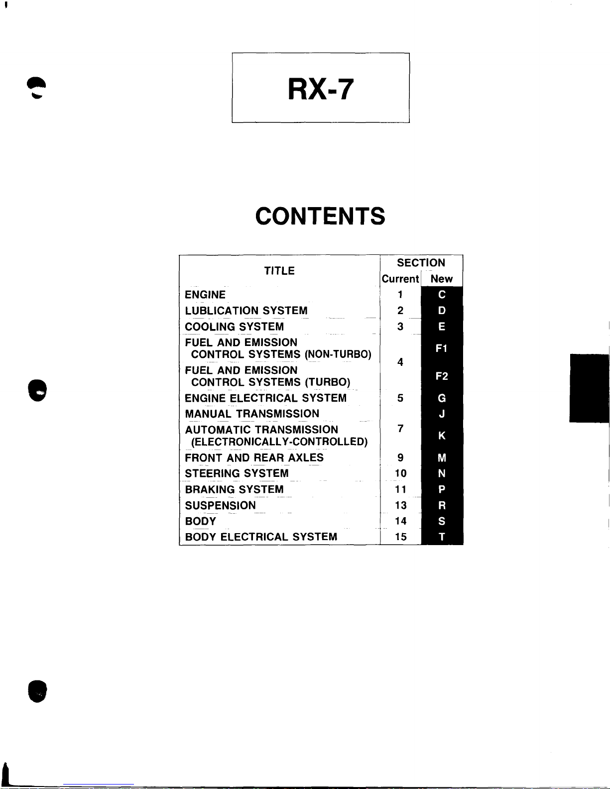
CONTENTS
•
TITLE
ENGINE
LUBLICATION
COOLING SYSTEM
FUEL AND EMISSION
CONTROL
-----
---
FUEL AND EMISSION
CONTROL
ENGINE ELECTRICAL SYSTEM
MANUAL
AUTOMATIC TRANSMISSION
(ELECTRONICALLY -CONTROLLED)
FRONT AND REAR AXLES
STEERING SYSTEM
BRAKING SYSTEM
SUSPENSION
BODY 14
BODY ELECTRICAL SYSTEM 15
-
--
--
---
--
--
-
SYSTEM
-
SYSTEMS
--- ---
SYSTEMS (TURBO)
--
TRANSMISSION
--
----
(NON-
----
-
--
-
-----
TURBO)
---
--
SECTION
1
2
3
4
5
7
9
10
11
13
•
c
-
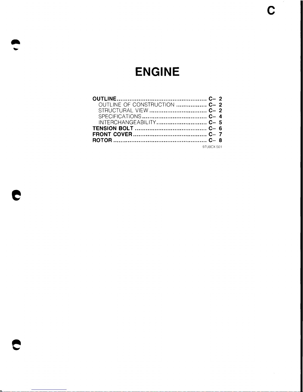
ENGINE
OUTLINE
..................................................
C-
2
OUTLINE OF CONSTRUCTION
.................
C-
2
STRUCTURAL VIEW
................................
C-
2
SPECIFICATIONS
....................................
C-
4
INTERCHANGEABILITY
............................
C-
5
TENSION BOLT
........................................
C-
6
FRONT COVER
.........................................
C-
7
ROTOR
....................................................
C-
8
97UOCX
501
e
e
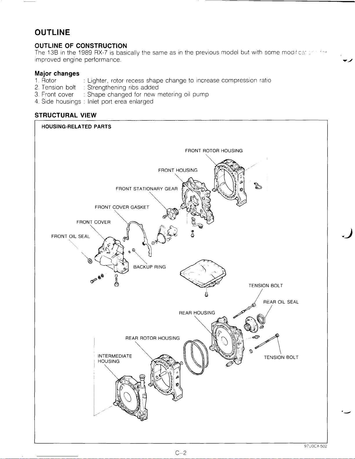
OUTLINE
OUTLINE OF CONSTRUCTION
The 13B
in
the 1989
RX-7
is
basically the same as
in
the previous model but with some modli
c:=:-
_
improved engine performance.
Major changes
1.
Rotor : Lighter, rotor recess shape change to increase compression ratio
2.
Tension bolt : Strengthening ribs added
3.
Front cover : Shape changed for new metering
oil
pump
4.
Side housings : Inlet port erea enlarged
STRUCTURAL VIEW
HOUSING-RELATED PARTS
FRONT ROTOR HOUSING
FRONT HOUSING
FRONT OIL SEAL
REAR HOUSING
REAR ROTOR HOUSING
INTERMEDIATE
HOUSING
C-2
97UOCX·502
._)
·-
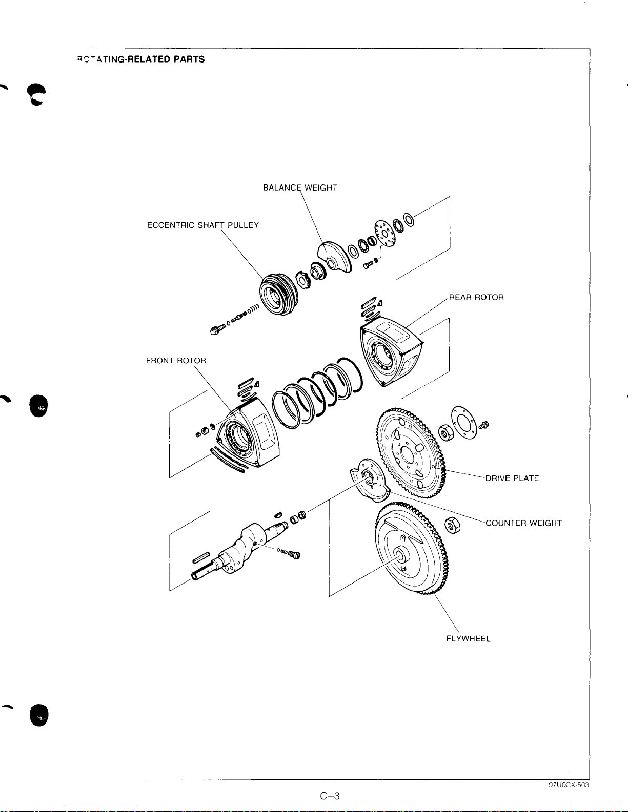
;:;'"'TA
~
TING-RELATED
PARTS
BALANCE WEIGHT
ECCENTRIC PULLEY
REAR ROTOR
' •
FRONT ROTOR
DRIVE PLATE
COUNTER WEIGHT
FLYWHEEL
-.
C-3
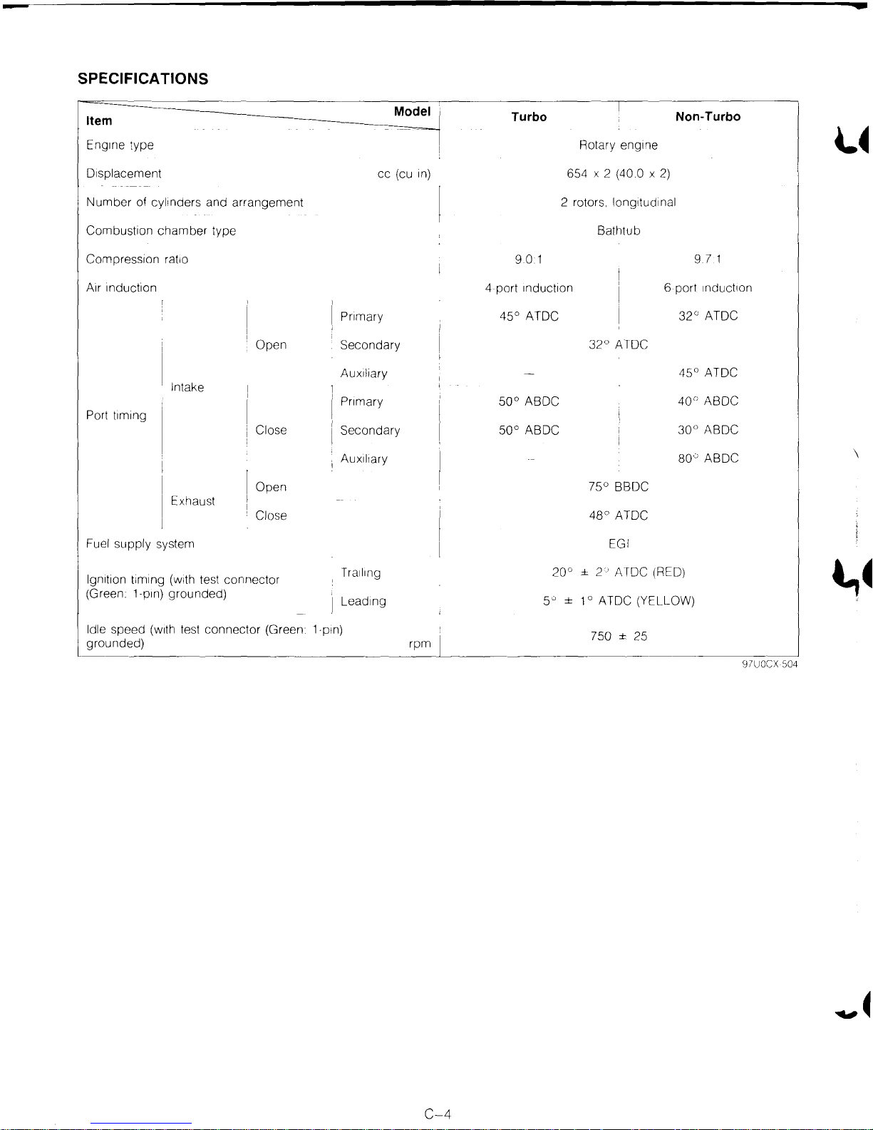
SPECIFICATIONS
cc
Model
(cu
1n)
Item
Eng1ne type Rotary eng1ne
Displacement
Number
Combustion
Compression
A1r
Port
of cyl1nders and
chamber
Induction
t1m1ng
rat10
Intake
Exhaust
arrangement
type
Open
Close
Open
Close
Pnmary 4S0 ATOC
Secondary
Auxiliary
Pnmary
Secondary
Auxil1ary
Turbo Non-Turbo
6S4 X 2 (40.0 X
2 rotors. longitudinal
Bathtub
9.0 1
4 port
1nduct1on
32°
ATOC
S0°
ABOC
soo
ABOC
0
7S
BBDC
48°
ATOC
2)
6 port
32°
4S
40°
30°
80"
9.7 1
1nduct1on
ATOC
0
ATOC
ABOC
ABOC
ABOC
~~
\
Fuel
supply
lgn1t1on
(Green
Idle
grounded)
t1ming
1-p1n)
speed
system EGI
(w1th
grounded)
(w1th
test
test
connector
connector
(Green
Tra1l1ng
Lead1ng
1-pln)
rpm
± 2 ' ATOC (REO)
20°
so
±
1 o ATOC (YELLOW)
750 ± 25
l,~
97UOCX 504
C-4
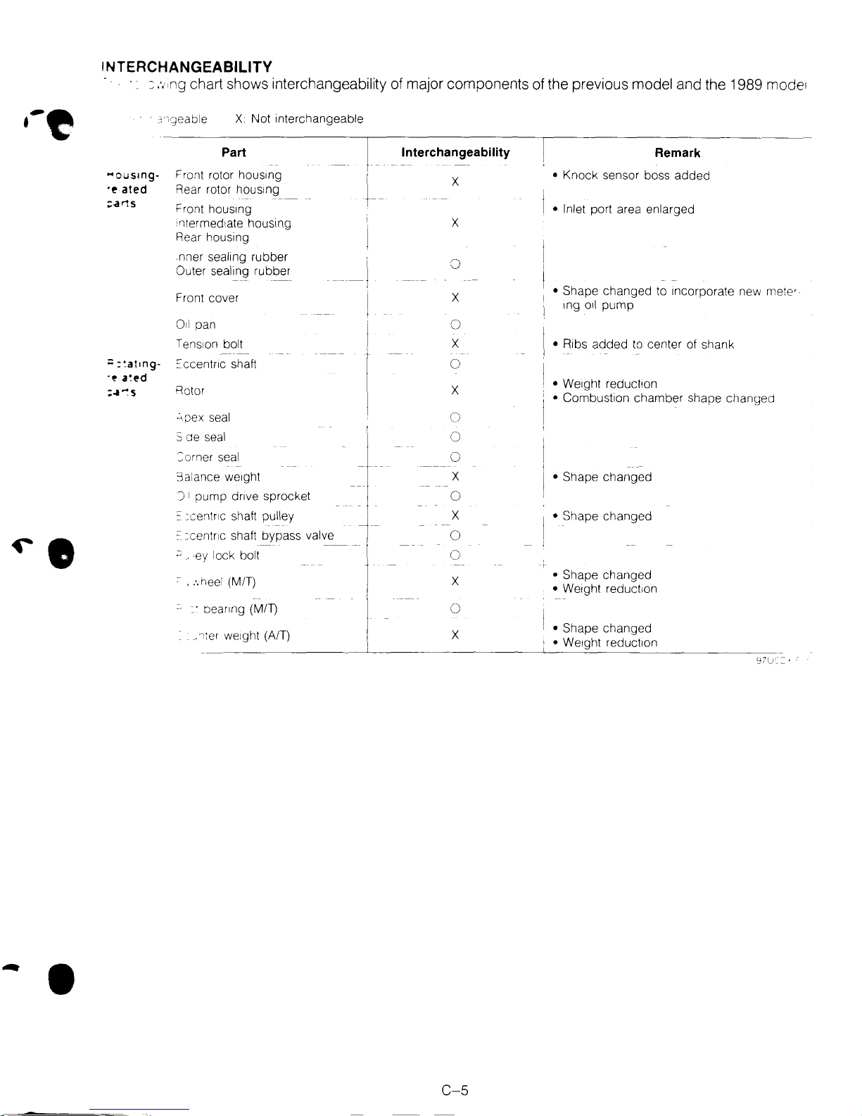
INTERCHANGEABILITY
:::
,.,,ng
chart shows interchangeability of major components of the previous model and the 1989 mode'
X Not interchangeable
...
ousmg-
·~
ated
;:.a
r1S
;;
:~at1ng-
-~
a~ed
=~~s
Part
Front rotor hous1ng
Rear rotor hous1ng
Front
hous1ng
i ntermed1ate housing
Rear housing
seal1ng
nner
Outer sealing rubber
Front cover
Orl
pan
Tens1on
::ccentnc shaft
Rotor
~~pex
S de
seal
:::orner
3a',ance weight I
J I pump dnve sprocket
: :centr1c
'C
=centnc shaft bypass valve - -
~
. ·ey lock bolt
~
.
:.
heel
• · beanng
.1ter
rubber
bolt
seal
seal
shaft pulley t
(MIT)
(MIT)
we1ght
(A/T)
-1
. -
i
---1
I
+
J
-~·
.
l
I,
Interchangeability
X
X
0
X
0
X
0
X
0
0
0
X
0
X
0
0
X
0
X
Remark
• Knock sensor boss added
• Inlet port area enlarged
• Shape changed to Incorporate new
tng
Oil
pump
• Ribs added
•
We1ght
•
Combustion chamber shape changed
• Shape changed
• Shape changed
• Shape changed
•
We1ght
•
Shape changed
•
We1ght
'
to
center of shank
reduct1on
reduct1on
reduct1on
metw
•
C-5
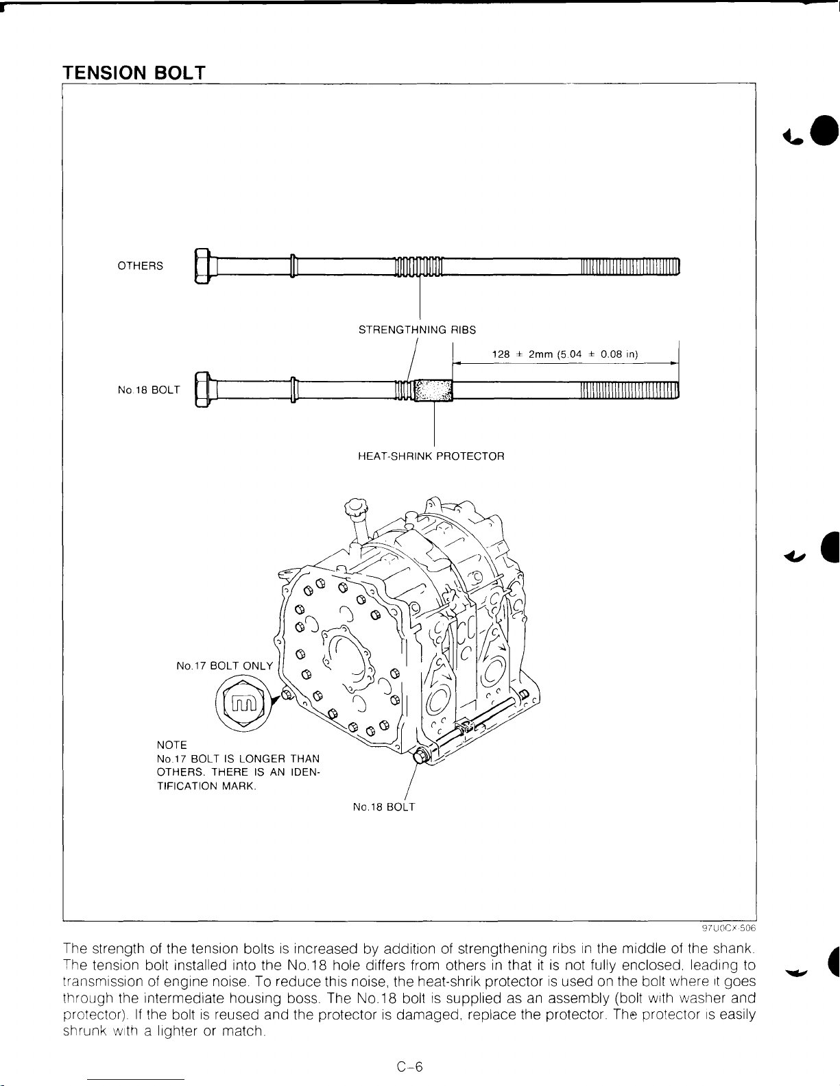
TENSION BOLT
OTHERS
(}1
No.18 BOLT
NOTE
No.1? SOL
T IS LONGER THAN
OTHERS. THERE IS AN IDENTIFICATION
MARK.
T
lllllllllllllllllllllllllllllll
STRENGTHNING RIBS
128 ± 2mm
(5.04 ± 0.08 in)
HEAT-SHRINK PROTECTOR
No.18 BOLT
97UOCI 506
The strength of the tension bolts
1s
increased by addit1on of strengthening ribs
in
the middle of the shank.
The tension
bolt installed into the No. 18 hole differs from others
in
that
it
is
not fully enclosed. lead1ng to
transmiss1on of eng1ne noise. To reduce this noise. the heat-shrik protector
is
used on the bolt where
1t
goes
through the intermediate housing boss. The No. 18
bolt
is
supplied as an assembly (bolt
w1th
washer and
protector).
If
the bolt
is
reused and the protector
is
damaged, replace the protector. The protector
1s
easily
shrunk
w1th
a l1ghter or match.
C-6
...
,
.•
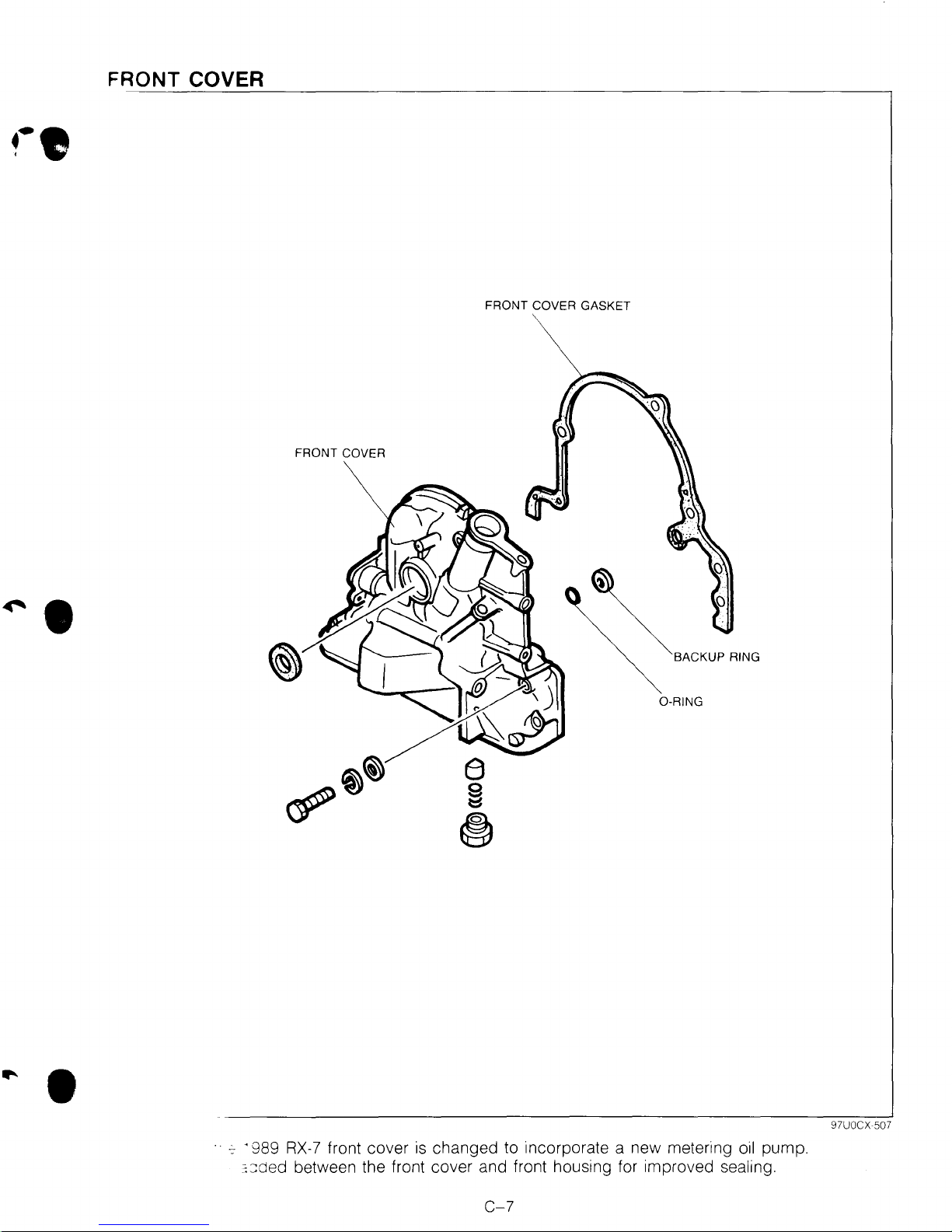
FRONT COVER
FRONT COVER GASKET
FRONT COVER
~.
~BACKUP
0-RING
RING
•
~
· 989
RX-7
:::::ded
between the front cover and front housing for improved sealing.
front cover
is
changed to incorporate a new metering
C-7
oil
97UOCX 507
pump.
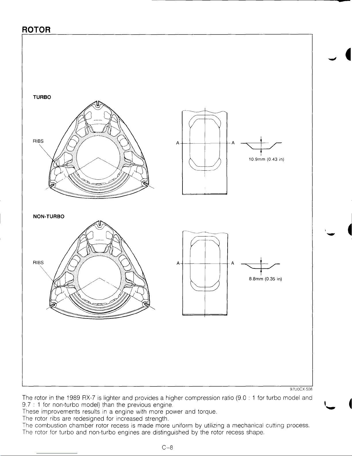
ROTOR
TURBO
RIBS
NON-TURBO
RIBS
~
~
\
A
/J
I
c--~~
v
A A
~
A~
1 0.9mm (0.43 in)
,_
4
8.8mm (0.35 in)
r---/1
~-
The rotor
9.7 :
These improvements
The rotor ribs are redesigned for increased strength.
The combustion chamber rotor recess
The rotor for turbo and non-turbo engines are distinguished by the rotor recess shape.
in
the 1989
1 for non-turbo model) than the previous engine.
RX-7
results
is
lighter and provides a higher compression ratio (9.0 : 1 for turbo model and
in
a engine with more power and torque.
1s
made more uniform by utilizing a mechanical cutting process.
97UOCX 508
C-8
D
...
LUBRICATION SYSTEM
OUTLINE
..................................................
D-
2
OUTLINE OF CONSTRUCTION
.................
D-
2
STRUCTURAL VIEW
................................
D-
2
SPECIFICATIONS
....................................
D-
3
INTERCHANGEABILITY
............................
D-
3
METERING OIL PUMP
...............................
D-
4
OUTLINE
...............................................
D-
4
OPERATION
...........................................
D-
5
FAIL-SAFE FUNCTION
.............................
D-
5
SERVICE POINT
.......................................
D-
6
OIL FILTER
............................................
D-
6
97UODX 501
-
-
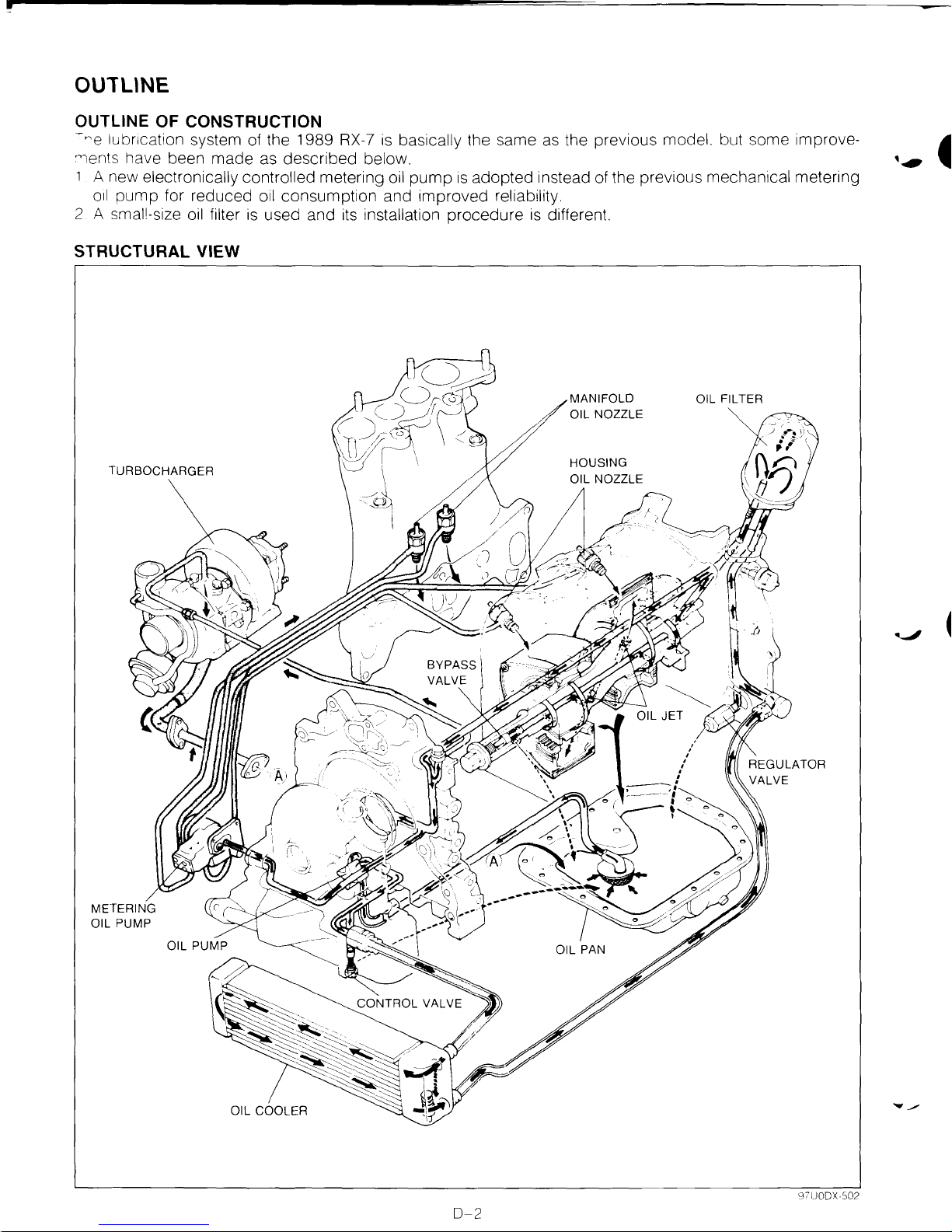
OUTUNE
OUTLINE OF CONSTRUCTION
-~e
lubncation system of the 1989
"lents have been made
1 A new electronically controlled metering
oil
pump for reduced
2 A smal!-size
oil
filter
as
described below.
oil
consumption and improved reliability.
is
used and
STRUCTURAL VIEW
RX-7
its
installation procedure
is
basically the same
oil
pump
is
adopted instead
as
the previous model. but some improve-
of
the previous mechanical metering
is
different.
MANIFOLD
OIL NOZZLE
TURBOCHARGER
HOUSING
0-2
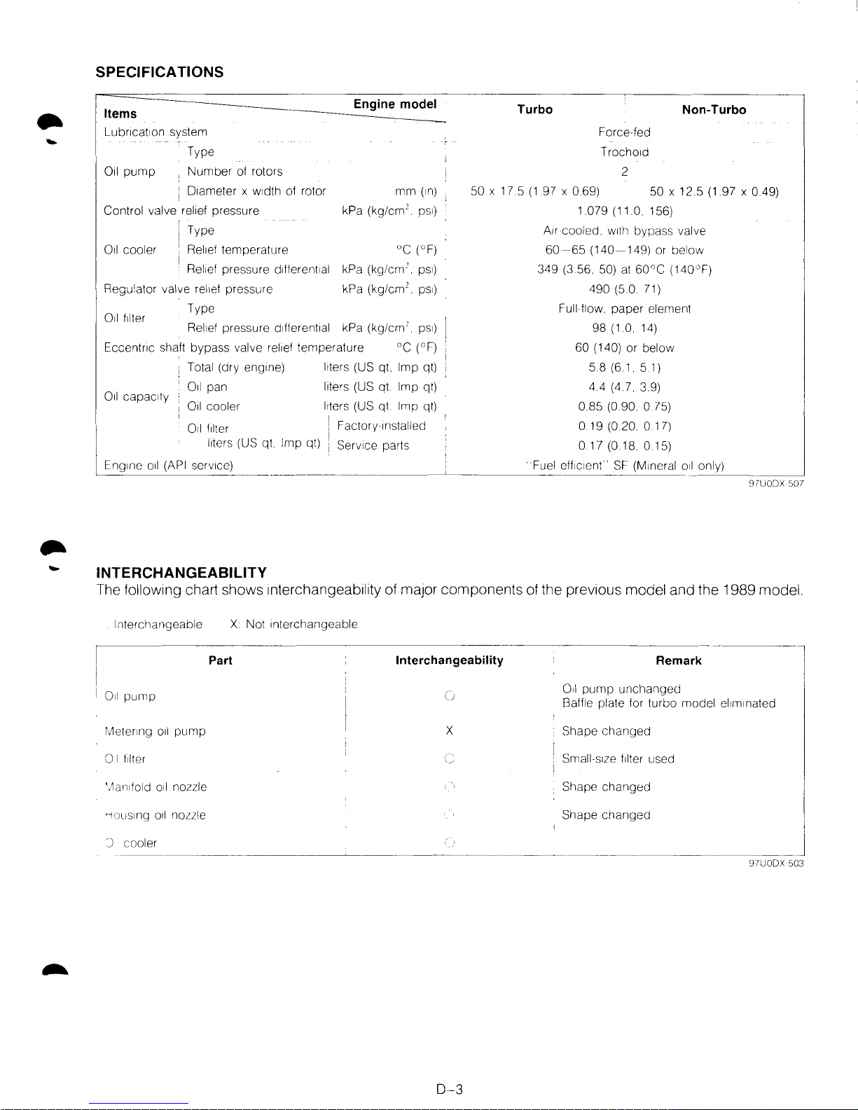
SPECIFICATIONS
Items
Engine model
Lubncat1on system
Type
011
pump
1
Number
of rotors
1 D1ameter x
w1dth
of rotor
Control valve relief pressure
mm
(1n)
kPa (kg/cm
2
.
ps1)
Oil cooler
Type
Rel1ef
temperature
oc
(°F)
Rel1ef
pressure dlfferent1al kPa
(kg/em'.
ps1)
Regulator valve
rel1ef
pressure kPa
(kg/em'.
ps1)
Type
Oil filter
Rel1ef
pressure
d1fferent1al
kPa
(kg/em'.
ps1)
Eccentnc shaft bypass valve
rel1ef
temperature
oc
(°F)
Oil
capaCity
Total (dry
eng1ne)
l1ters
(US qt. Imp qt)
011
pan
Oil cooler
liters
(US qt. Imp qt)
l1ters
(US
qt
Imp
qt)
\ F
011
filter , actory-1nstalled
I
l1ters
(US qt Imp qt) i Serv1ce parts
Turbo
Force-fed
Trocho1d
2
Non-Turbo
50 X 17.5
(1
97 X
069)
50 X 12.5 (1.97 X 0.49)
1.079 (11.0.
156)
A1r
cooled.
w1th
bypass valve
60-65
(140-149)
or below
349
(3
56. 50)
at
60°C
(140"F)
490 (5.0. 71)
Full flow.
paper
element
98
(1.0. 14)
60 (140) or below
5.8 (6 1 5.1)
4.4 (4.7. 3
9)
0.85 (0.90. 0
75)
0.19 (0.20 0 17)
0.17 (0.18. 0 15)
Eng1ne
oil
(API
serv1ce)
Fuel
eff1c1enr·
SF
(M1neral oil only)
_____
_[_________
----
___
_j
97UODX
507
INTERCHANGEABILITY
The following chart shows interchangeability of major components of the previous model and the 1989 model.
Interchangeable X Not Interchangeable
Part
Interchangeability
Remark
011
pump
Oil
pump
unchanged
Baffle plate for turbo model
el1m1nated
rl1eterlllg
oil
pump
X
Shape
changed
0 I
f1lter
Small-s1ze filter used
Shape
changed
--1ous1ng
oil
nozzle Shape cr1anged
J
_c_o_o_le_r
______________
~
______________________________
j
97UODX
503
0-3
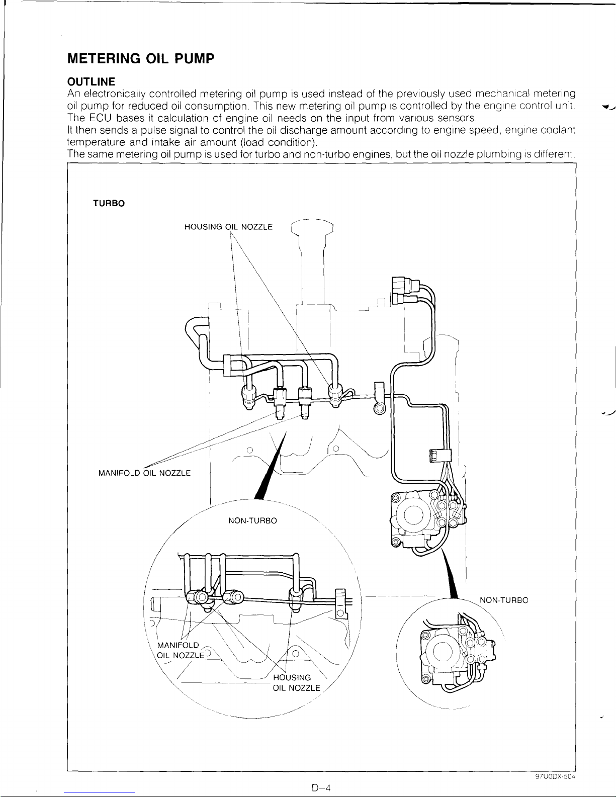
METERING OIL PUMP
OUTLINE
An electronically controlled metering
oil
pump
The ECU bases
It
then sends a pulse signal to control the
for reduced
it
calculation of engine
oil
consumption. This new metering
temperature and intake air amount (load condition).
The same metering
TURBO
oil
pump
is
used for turbo and non-turbo engines, but the
HOUSING OIL NOZZLE
oil
pump
is
used instead of the previously used mechan1cal metering
oil
needs on the input from various sensors.
oil
discharge amount according to engine speed,
oil
pump
is
controlled by the
oil
nozzle plumbing
eng1ne
eng1ne
control unit.
coolant
1s
different
...
~
MANIFOLD OIL NOZZLE
NON-TURBO
~
I
NON-TURBO
97UODX·504
0-4
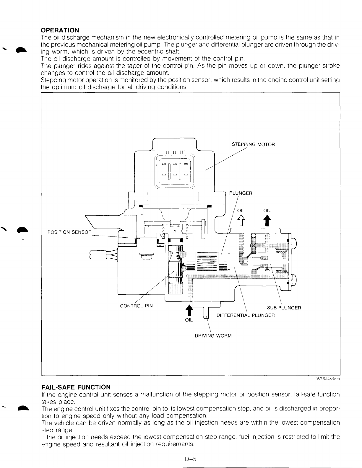
OPERATION
The
oil
discharge mechanism
in
the new electronically controlled metering oil pump
is
the same
as
that
in
the previous mechanical metering
oil
pump. The plunger and differential plunger are driven through the driv-
ing worm, which
is
driven by the eccentric shaft.
The
oil
discharge amount
is
controlled by movement
of
the control
p1n.
The plunger rides against the taper
of
the control pin.
As
the
p1n
moves up or down, the plunger stroke
changes to
control the
oil
discharge amount.
Stepping motor operation
is
monitored by the
pos1t1on
sensor, which results
in
the engine control unit setting
the optimum
oil
discharge for
all
driving conditions.
CONTROL PIN
f
OIL
FAIL-SAFE FUNCTION
STEPPING MOTOR
/
SUB-PLUNGER
DIFFERENTIAL PLUNGER
DRIVING WORM
97UODX 505
If
the engine control unit senses a malfunction of the stepping motor or
posit1on
sensor. fail-safe function
takes
place.
The engine control unit fixes the control pin to
its
lowest compensation step, and
oil
is
discharged
in
propor-
tion to engine speed
only without any load compensation.
The
vehicle can be driven normally
as
long
as
the
oil
injection needs are within the lowest compensation
step range.
' the
oil
injection needs exceed the lowest compensation step range. fuel injection
is
restricted to limit the
~1gine
speed and resultant oil injection requirements.
D-5
SERVICE POINT
OIL FILTER
The 1989
The service oil filter
RX-7
has a small-size
is
oil
filter. The factory-installed oil filter differs from the service parts oil filter.
the same as that used for the Mazda 323 B-series engine. '
.....
Oil filter capacity
ctory 1nstalled
rvice part
-
--·-----·-----
019
0.17
(0.20, 0.17)
(0
18.
0.15)
liters (US qt,
_,]
Imp
qt)
97UODX 508
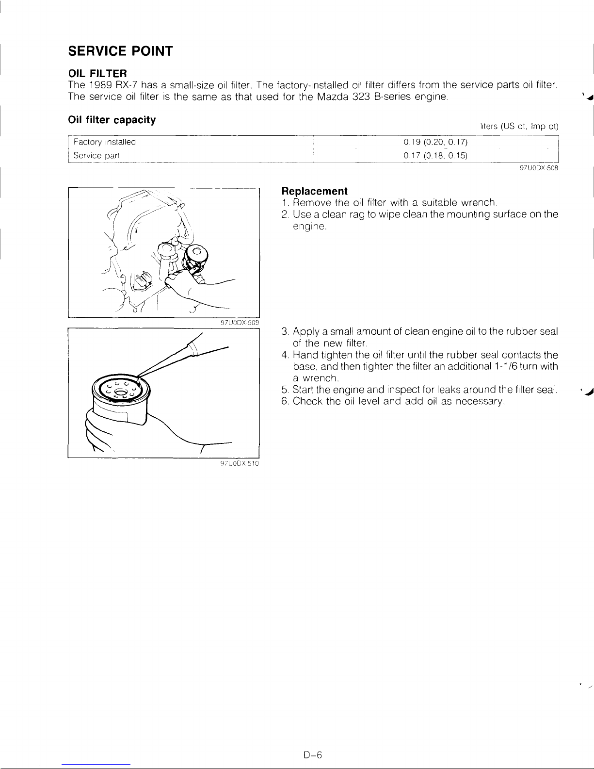
Replacement
1.
Remove the oil filter with a suitable wrench.
2.
Use a clean rag to wipe clean the mounting surface on the
engine.
3.
Apply a small amount of clean engine oil to the rubber seal
of the new filter.
4.
Hand tighten the oil filter until the rubber seal contacts the
base, and then tighten the filter an additional 1-1/6 turn with
a wrench.
5.
Start the engtne and inspect for leaks around the filter seal. ·
6.
Check the oil level and
add
oil as necessary.
.J
0-6
COOLING SYSTEM
E
OUTLINE
OUTLINE OF CONSTRUCTION
STRUCTURAL VIEW
SPECIFICATIONS
INTERCHANGEABILITY
COOLING FAN
WATER PUMP
THERMOSTAT
RADIATOR
..................................................
................................
....................................
............................
..........................................
..........................................
..........................................
...............................................
..................
E-
EEE-
E-
EEEE-
97UOEX 501
2
2
2
3
3
4
5
6
7
-
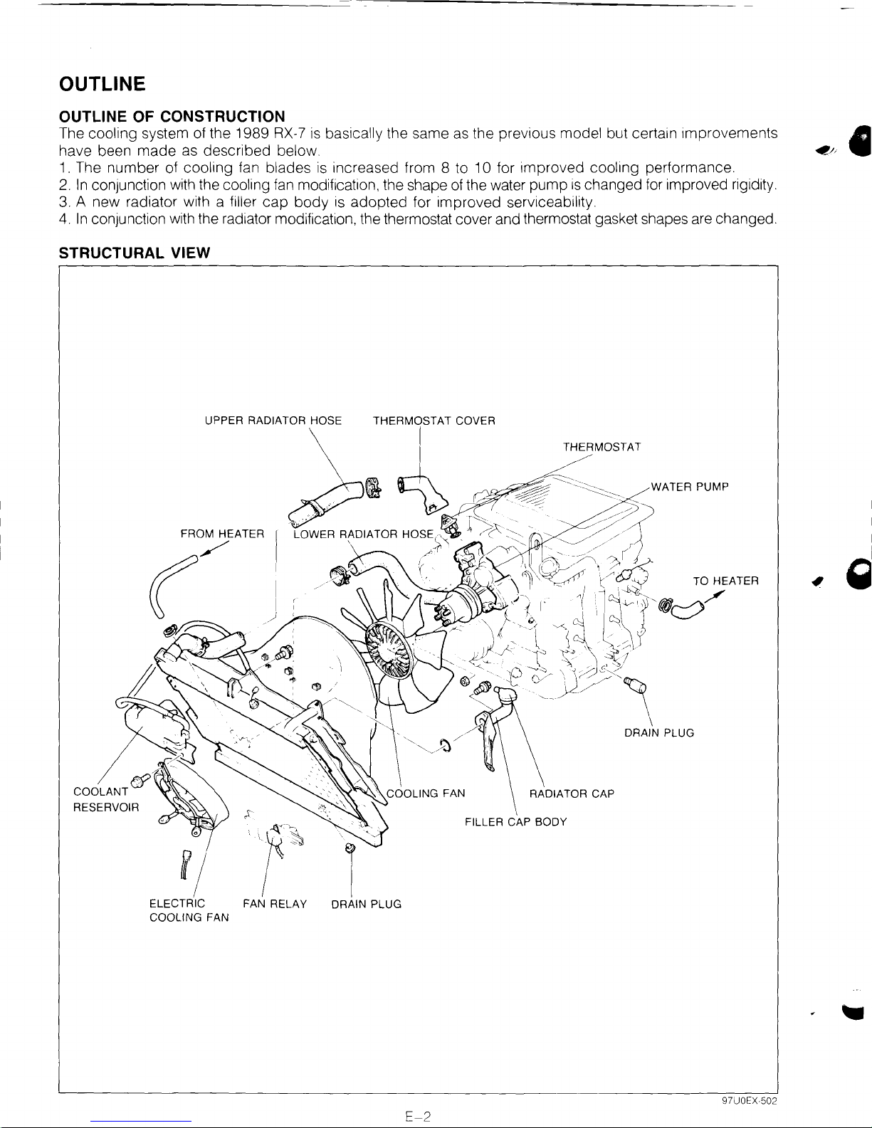
OUTLINE
OUTLINE
The cooling system of the 1989
have been
1.
The number of cooling fan blades
2.
In
3.
A new radiator with a filler
4.
In
OF
CONSTRUCTION
RX-7
is
basically the same as the previous model but certain improvements
made
conJunction with the cooling
conjunction with the radiator modification, the thermostat cover and thermostat gasket shapes are changed.
as described below.
fan
modification, the shape of the water pump
cap
body
is
increased from 8 to 1 0 for improved cooling performance.
is
changed for improved rigidity.
is adopted for improved serviceability.
STRUCTURAL VIEW
THERMOSTAT
~
WATER PUMP
RESERVOIR
FROM HEATER
(/
fj
ELECTRIC
COOLING
FAN
FAN RELAY
RADIATOR CAP
FILLER CAP BODY
DRAIN PLUG
97UOEX-502
E-2
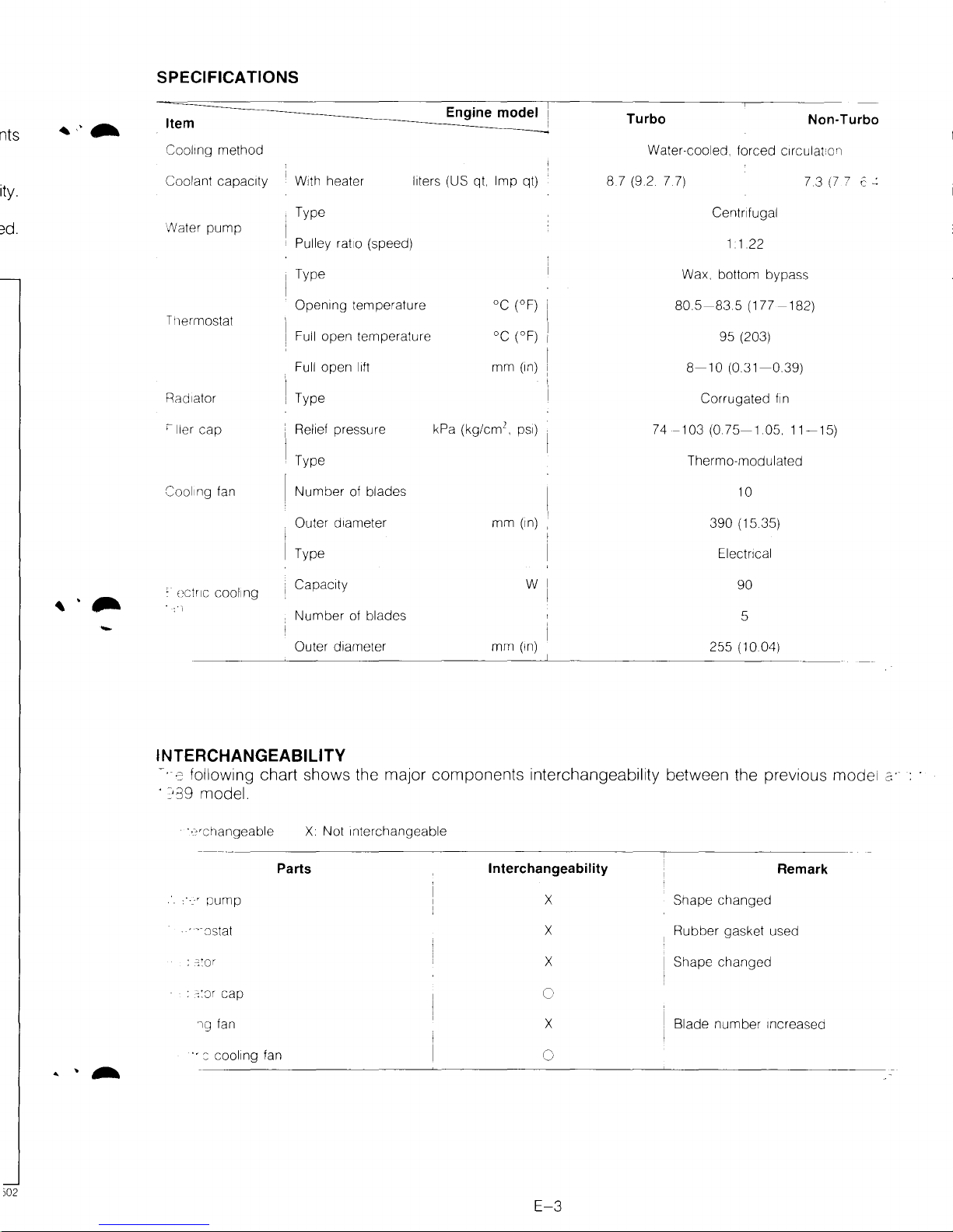
SPECIFICATIONS
nts
Item
Cool1ng
Coolant capac1ty
/Vater
Tl1ermostat
Rad1ator
'ller
Cool1ng fan
method
pump
cap
W1th
heater
Type
Pulley
rat1o
Type
Open1ng
Full
Full
[
Type
Relief pressure
Type
Number
Outer
Type
temperature
ope'l
open
of blades
d1ameter
liters (US qt.
(speed)
temperature
l1ft
Engine
kPa
mode~
Imp
°C
oc
mm
2
(kg/cm
•
mm
qt)
(°F) i
(oF) i
(1n)
ps1)
(1n)
Turbo
Water-cooled,
8.7 (9.2 7.7)
forced
Ce'ltnfugal
Non-Turbo
c1rculat:o'l
7.3
(7
7 c
~
1 1.22
Wax. bottom
I
80.5-83.5
95
I
8-10
Corrugated
74-103
(0.75-1.05.
Thermo-modulated
bypass
(177
-182)
(203)
(0.31-0.39)
f1n
11-15)
10
390
(15 35)
Electncal
-
mm
w
(1n)
255
90
5
(10.04)
:
(;CtriC
COOling
i Capac1ty
Number
Outer d1ameter
of blades
INTERCHANGEABILITY
~.
;co
following chart shows the major components interchangeability between the previous model
· ?39 model.
· ·_?•changeable
· ":Jstat
:
c::or
:
:::Jr
cap
'lQ fan
Parts
X
Not
Interchangeable
Interchangeability
X
X
X
c
X
Shape
Rubber
Shape
Blade
changed
gasket used
changed
number
Increased
Remark
c:·
··::
::ooling fan
)02
0
E-3
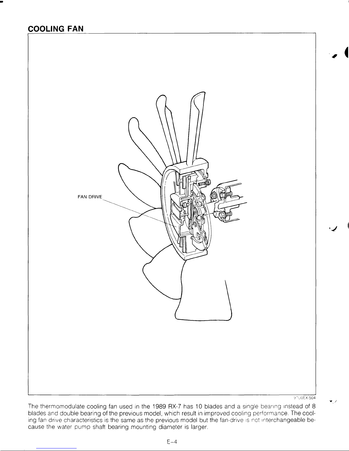
COOLING FAN
FAN DRIVE
The thermomodulate cooling fan used
blades and double bearing of the previous model, which result
ing fan drive characteristics
cause the water
pump
is
the same as the previous model but the fan-dr1ve
shaft bearing mounting diameter
in
the 1989 RX-7 has 10 blades and a
in
improved cooling performance. The cool-
is
larger.
E-4
s1ngle
bear1ng 1nstead of 8
1s
not Interchangeable be-
•_/

"'
\ -
-
WATER PUMP
SHAFT BEARING
PULLEY BOSS
\
@~
I
I
WATER PUMP BODY
EXTRA RIBS
BEARING HOUSING
WATER
PUMP GASKET
97UOEX
505
:.
:=::er
pump shape
is
changed to incorporate the new cooling fan and thermostat.
•.
·-g
housing : Extra ribs are used for improved rigidity.
·-.·
:Jump gasket : The shape
is
changed because of the bearing housing change .
...
:::earing and pulley boss : The shaft bearing shaft outer diameter and pulley boss inner diameter are
increased to incorporate the new
cooling fan.
·.
· :Jump body : The body shape
is
changed to incorporate the new thermostat and cov-
er. The water thermoswitch for automatic transmission and Turbo
models
is
in
the
pump
body.
·-=-·~al
parts are interchangeable with the previous
RX-7.
E-5
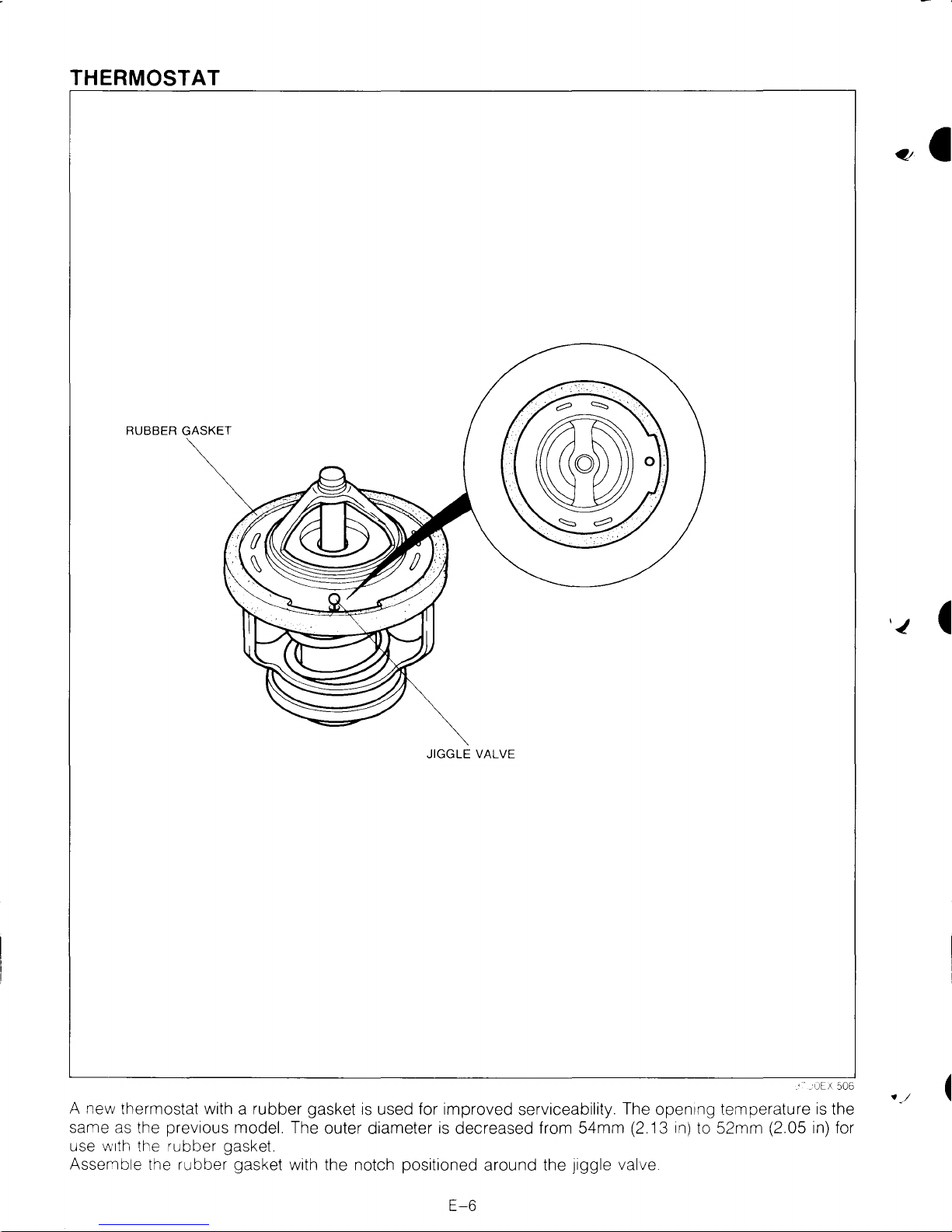
THERMOSTAT
RUBBER GASKET
VALVE
is
decreased from 54mm (2.13
A new thermostat with a rubber gasket
same
as
the prev1ous model. The outer diameter
use
w1th
the rubber gasket.
JIGGLE
is
used for improved serviceability. The open1ng temperature
Assemble the rubber gasket with the notch positioned around the Jiggle valve
1n)
to 52mm (2.05
is
in)
the
for
E-6
'
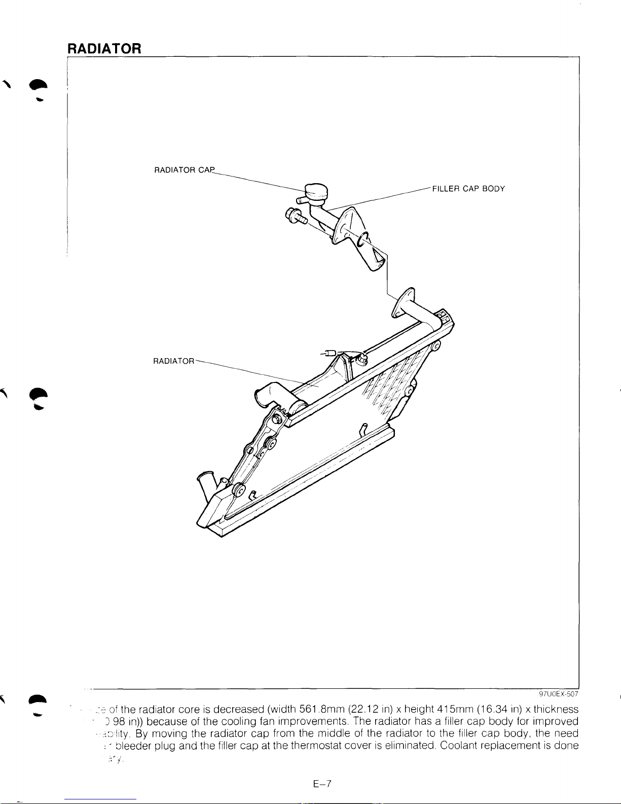
RADIATOR
..
RADIATOR CAP
FILLER CAP BODY
RADIATOR
.:::::of
the radiator core
J 98
in))
-
· :::J
l1ty.
, - bleeder plug and the filler cap at the thermostat cover
':'j
because of the cooling fan improvements. The radiator has a filler cap body for improved
By moving the radiator cap from the middle of the radiator to the filler
is
decreased (width
561
.Smm (22.12
E-7
in)
x height 415mm (16.34
is
eliminated. Coolant replacement
in)
cap
body, the need
97UOEX-507
x thickness
is
done
•
•
FUEL
AND
EMISSION
CONTROL SYSTEMS
{NON-
TURBO)
OUTLINE
................................................
F1-
2
OUTLINE OF CONSTRUCTION
................
F1-
2
EMISSION CONTROL SCHEMATIC
DIAGRAM
...........................................
F1-
4
SYSTEM DIAGRAM
................................
F1-
8
VACUUM
HOSE ROUTING DIAGRAM
.......
F1-
9
WIRING DIAGRAM
.................................
F1-10
SPECIFICATIONS
...................................
F1-11
VARIABLE DYNAMIC EFFECT INTAKE
(VDI) SYSTEM
.......................................
F1-12
FUEL SYSTEM
........................................
F1-13
MIXING PLATE
......................................
F1-13
SERVICE POINT
....................................
F1-14
CONTROL SYSTEM
.................................
F1-15
AIRFLOW METER
..................................
F1-15
THROTTLE-IDLE-POSITION AUTO-
ADJUSTING SYSTEM
...........................
F1-16
LEAN BEST-IDLE CONTROL SYSTEM
.......
F1-17
SPARK ADVANCE FEEDBACK SYSTEM
....
F1-18
SERVICE POINT
....................................
F1-19
SELF-DIAGNOSIS FUNCTION
...................
F1-20
DESCRIPTION
.......................................
F1-20
MALFUNCTION
CODE
NUMBER
.............
F1-21
SWITCH MONITOR FUNCTION
................
F1-25
'J7UOII
c,[11
F1
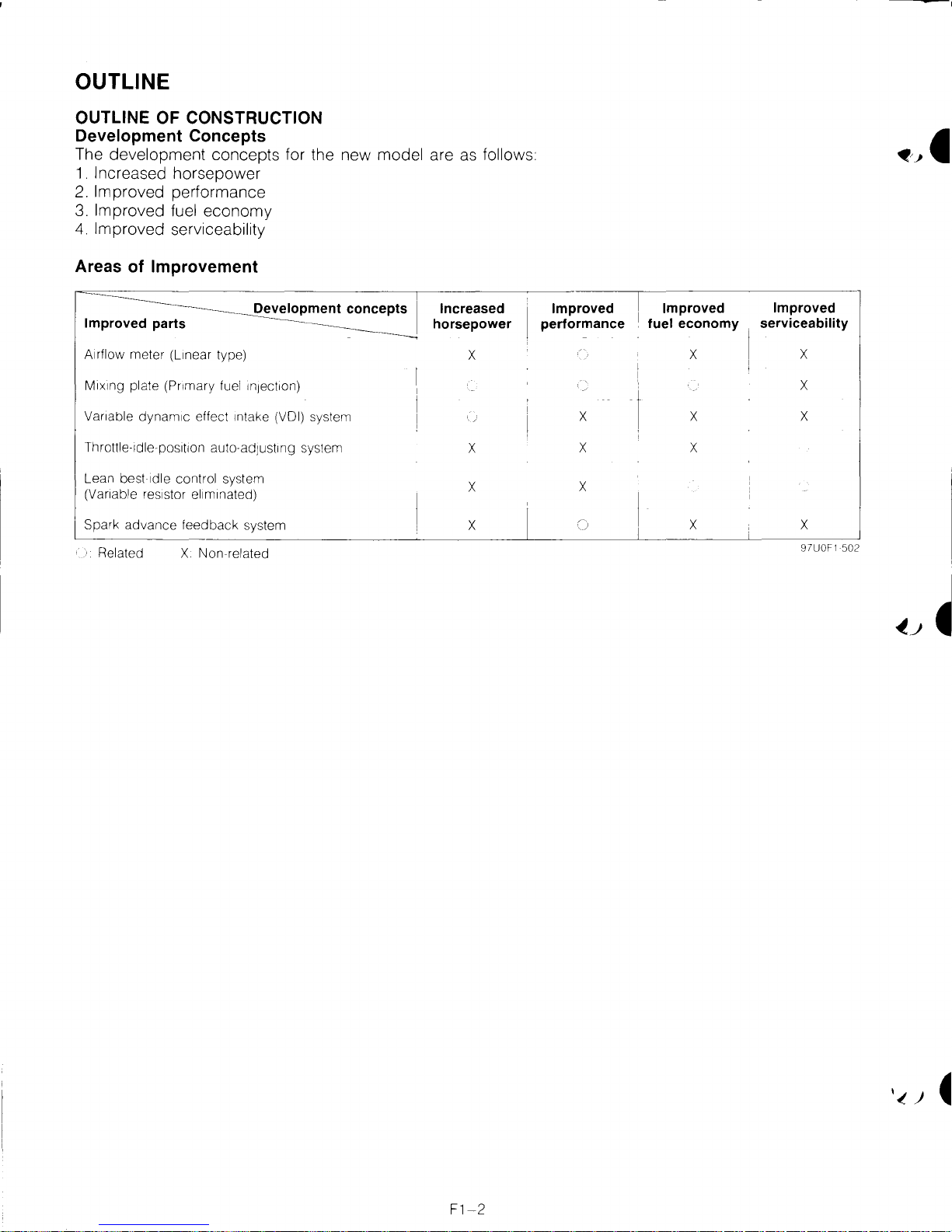
OUTLINE
OUTLINE OF CONSTRUCTION
Development
The
development concepts for the new model are
1.
Increased horsepower
2.
Improved performance
3.
Improved fuel economy
4.
Improved serviceability
Concepts
as
follows
Areas of
Improved parts
Airflow
M1x1ng
Vanable
Throttle-1dle-pos1t1on auto-adJUSting system
Lean best
(Vanable res1stor el1m1nated)
Spark
'.
Related X
Improvement
Development concepts
meter
(L1near type)
plate
(Pnmary
dynam1c effect 1ntake (VOl) system
1dle
advance
fuel
1nJ8ct1on)
control system
feedback
Non
system
related
Increased
horsepower
X
X
X
X
Improved
performance
X
X
X
Improved
fuel
I
I
economy
X
X
X
X
Improved
serviceability
X
X
X
X
97UOF1 502
 Loading...