

Page 1
SERIAL ATA HARD DRIVE
Installation Guide
English, Français, Deutsch
P/N: 20257700
Page 2

FCC Declaration of Conformance
This device complies with part 15 of the FCC Rules. Operation is subject to the following two conditions: (1) this device may not cause harmful interference,
and (2) this device must accept any interference received including interference that may cause undesired operation.
Déclaration de conformité FCC
Ce périphérique est conforme à l'article 15 de la norme FCC. L'exploitation est soumise aux deux conditions suivantes : (1) ce périphérique ne doit pas causer
d'interférence nuisible et (2) ce périphérique doit accepter toutes les interférences reçues, y compris les interférences responsables de comportements indésirés.
Konformitätserklärung mit den Bestimmungen des FCC
Dieses Gerät erfüllt Abschnitt 15 der FCC-Bestimmungen. Der Betrieb des Geräts unterliegt folgenden zwei Beschränkungen: 1.) Das Gerät darf keine gesundheitsschädliche Strahlung abgeben. 2.) Dieses Gerät muss Strahlung ausgesetzt werden können, die möglicherweise Betriebsstörungen hervorrufen.
Page 3

English
Contents
Warranty Registration Information
. . . . . . . . . . . . . . . . . . . . . . . . . . . . . . 1
Introduction
. . . . . . . . . . . . . . . . . . . . . . . . . . . . . . . . . . . . . . . . . . . . . . . . . . . . 2
Precautions . . . . . . . . . . . . . . . . . . . . . . . . . . . . . . . . . . . . . . . . . . . . . . . . . . . . . 2
Included in this Kit. . . . . . . . . . . . . . . . . . . . . . . . . . . . . . . . . . . . . . . . . . . . . . . . 2
Required Tools . . . . . . . . . . . . . . . . . . . . . . . . . . . . . . . . . . . . . . . . . . . . . . . . . . 3
About Serial ATA . . . . . . . . . . . . . . . . . . . . . . . . . . . . . . . . . . . . . . . . . . . . . . . . . 3
Back Up Your Data . . . . . . . . . . . . . . . . . . . . . . . . . . . . . . . . . . . . . . . . . . . . . . . 3
Installing the Drive in a Macintosh . . . . . . . . . . . . . . . . . . . . . . . . . . . . . . . . . . . 3
Remove System Cover
. . . . . . . . . . . . . . . . . . . . . . . . . . . . . . . . . . . . . . . . . . 4
Mount the Hard Drive
. . . . . . . . . . . . . . . . . . . . . . . . . . . . . . . . . . . . . . . . . . .
5
Attach Serial ATA and Power Cables
. . . . . . . . . . . . . . . . . . . . . . . . . . . . . 7
Check BIOS Message
. . . . . . . . . . . . . . . . . . . . . . . . . . . . . . . . . . . . . . . . . . . . 9
Format the Hard Drive
. . . . . . . . . . . . . . . . . . . . . . . . . . . . . . . . . . . . . . . . . . 10
Set the Boot Sequence
. . . . . . . . . . . . . . . . . . . . . . . . . . . . . . . . . . . . . . . . . 15
Getting Help
. . . . . . . . . . . . . . . . . . . . . . . . . . . . . . . . . . . . . . . . . . . . . . . . . . . 16
Page 4
1 Warranty Registration Information
English
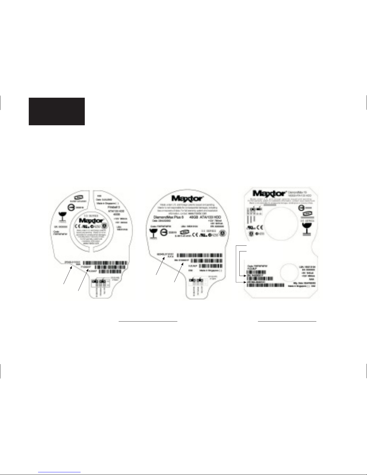
Warranty Registration Information
Before installing the hard drive, please write down the 8 character serial number and the 14 digit part number information. If
you ever need to contact Maxtor Support, you must provide this information about your hard drive prior to assistance.
Several hard drive models are illustrated below to help you identify where these numbers are located. Use the drawing that
looks like your hard drive, then locate the part and serial numbers from your hard drive and write these numbers in the space
provided.
Part Number (P/N): Serial Number (S/N):
Part Number
Serial Number
Part Number
Serial Number
Part Number
Serial Number
Page 5
Introduction 2
English
Introduction
Thank you for selecting a Maxtor hard drive product. This guide will lead you
through the installation of your new drive.
If you encounter any difficulties with installation, please visit us online at
www.maxtor.com
and click on Worldwide Support.
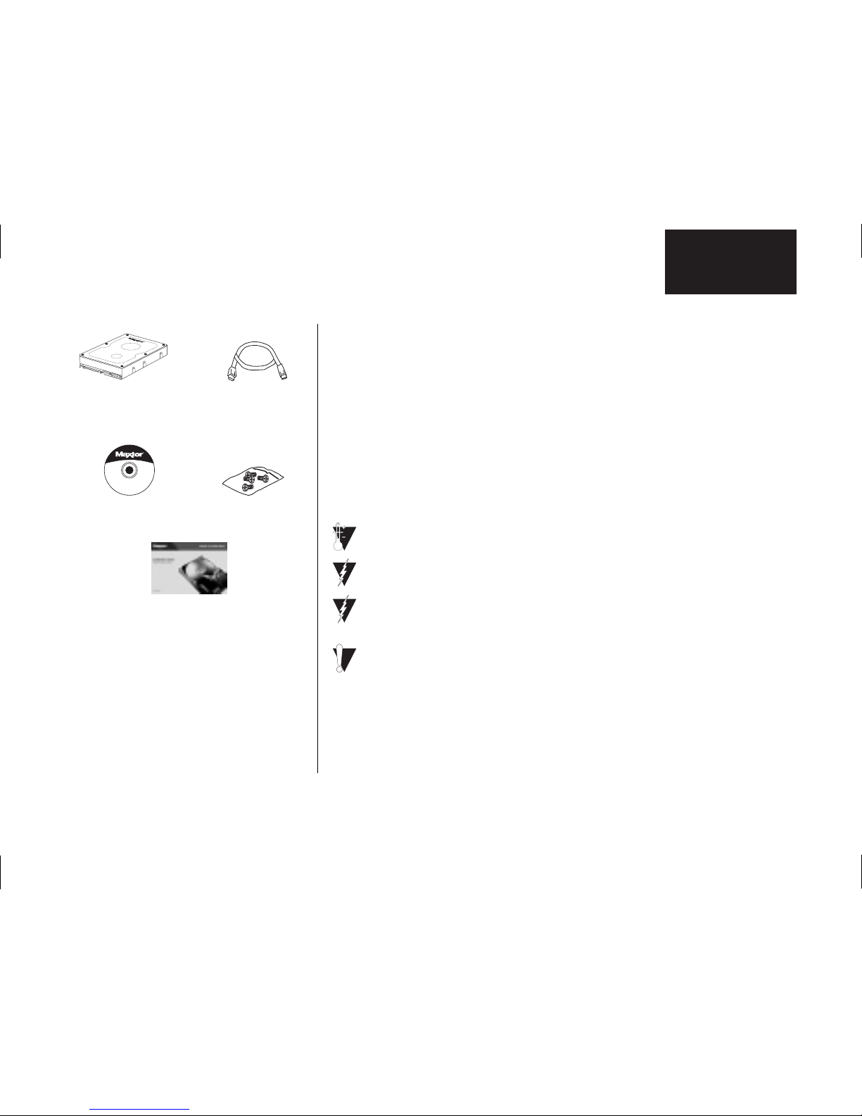
The Maxtor SATA Hard Drive Kit includes the components shown in Figure 1.
Your computer may need some or all of these parts to complete the installation.
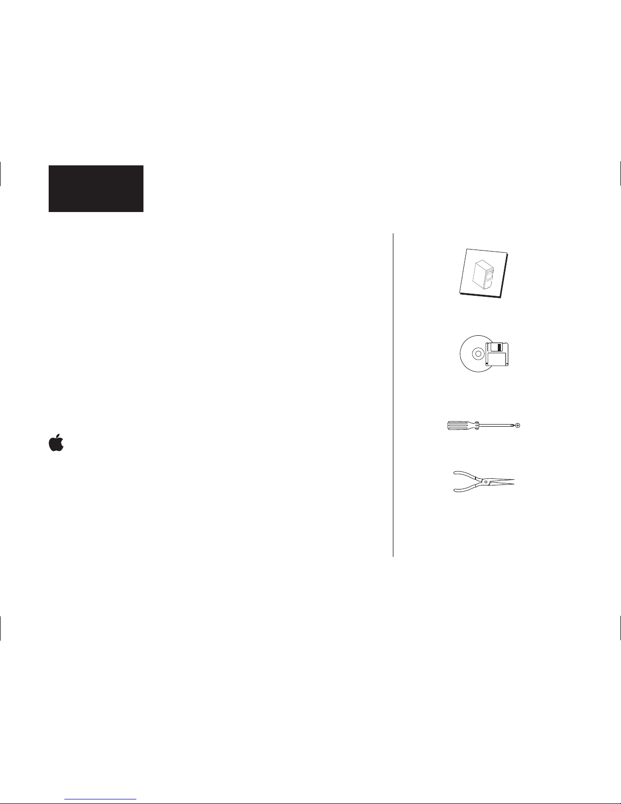
You will also need the tools shown in Figure 2 on page 3 to install the hard drive
in your computer.
Precautions
Drive should be at room temperature before installing.
Do not touch circuit board on drive.
Unplug system from electrical outlet before connecting
cables to drive or motherboard.
Do not drop, bump, or jar drive.
SATA Interface
Cable
This Installation
Guide
MaxBlast
®
CD
Mounting Screws
Max•Blast
™
Maxtor Serial ATA
(SATA) Hard Drive
Figure 1
Included in this Kit
Page 6
3Introduction
English
About Serial ATA
Serial ATA (SATA) technology offers you the following benefits:
• World’s fastest ATA interface
• Ideal for high-performance RAID
• Thin, easy-plug cables for improved airflow
• Simple, no-jumper installation
Unlike standard ATA drives, Serial ATA drives do not require the use of jumpers
to configure the drive.
Visit www.maxtor.com and click on Worldwide Support for the latest SATA
information and software updates.
Back Up Your Data
Protect your data by backing up existing hard drives before installing your new
Maxtor hard drive.
Installing the Drive in a Macintosh
For detailed information on mounting an internal drive in your Macintosh, go to
www.apple.com/support. Once you have mounted the drive, you can format
(initialize) and partition the drive using the Apple's Drive Setup utility (for Mac
OS 8.6 or higher) or Disk Utility (for Mac OS X). Note that on all beige Power
Mac G3 systems (Desktop, Minitower, All-In-One), Mac OS X can only be
installed in a partition that is within the first 8 GB of the drive.
System
M
anual
System User Manual
Operating System
CD and Boot Disk
Philips Screwdriver
Small Needle-Nose Pliers
Figure 2
Required Tools
Page 7
Remove System Cover 4
English
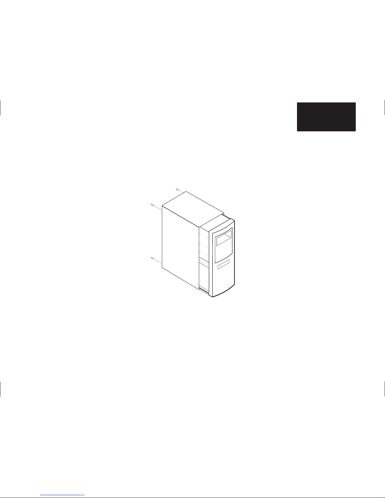
Remove System Cover
1.
Turn your computer off.
2.
Unplug your system from the electrical outlet.
3.
Remove the cover from your system case. See Figure 3.
4. Attach a grounding strap or touch a metal portion of your computer case. This will
ground you to minimize the risk of exposing the hard drive to electrostatic discharge.
Figure 3
Removing the System Cover
Refer to your system user
manual for instructions on
removing the cover, or obtain
the services of a qualified
installation technician.
Page 8
5 Mount the Hard Drive
English
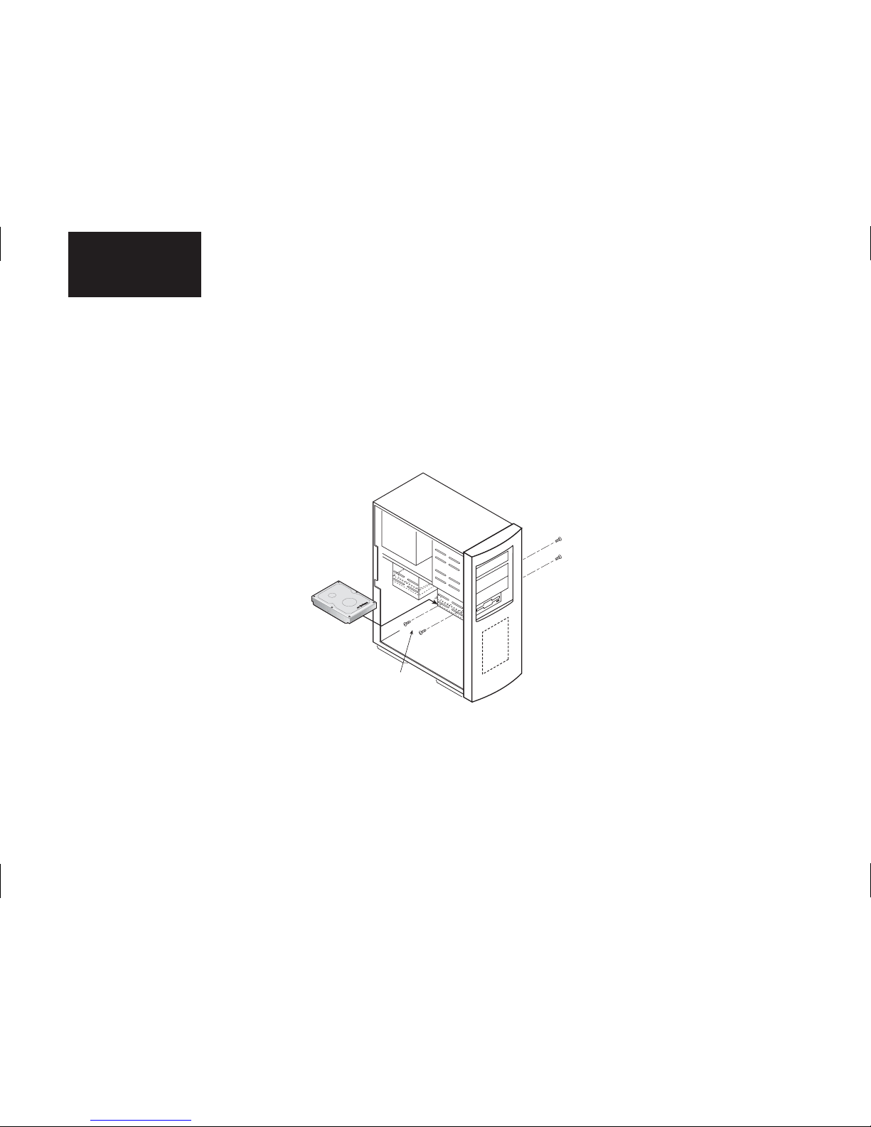
Mount the Hard Drive
Before mounting the hard drive in your system, determine whether you are installing the hard drive in a 3.5-inch or 5.25-inch
device bay. If you are unable to locate an available device bay, consult your system manual or system manufacturer.
3.5-inch Device Bay Installation
Many systems have an available 3.5-inch bay located adjacent to the floppy drive.
• Mount the hard drive in the 3.5-inch bay using the screws provided. See Figure 4.
Mounting
Screws
Some systems may not have
enough room to plug in the cables
after the hard drive is mounted.
You may need to attach the SATA
and power supply cables first.
Figure 4
Typical 3.5-inch Device Bay Installation
Page 9

Mount the Hard Drive 6
English
5.25-inch Device Bay Installation
When installing the hard drive in a 5.25-inch bay (such as where CD-ROM drives are typically installed), you first need to attach
mounting brackets (not included) to the hard drive. Mounting brackets are available from your local computer hardware store.
1.
Attach the mounting brackets to the hard drive using the screws included with this kit. See Figure 5 for details.
2.
Mount the hard drive in the 5.25-inch bay using the screws provided with the mounting brackets. Position the hard drive as
close to the bottom of the device bay as possible with the label facing up.
Figure 5
Mounting the Brackets on the Hard Drive
Page 10
7Attach Serial ATA and Power Cables
English
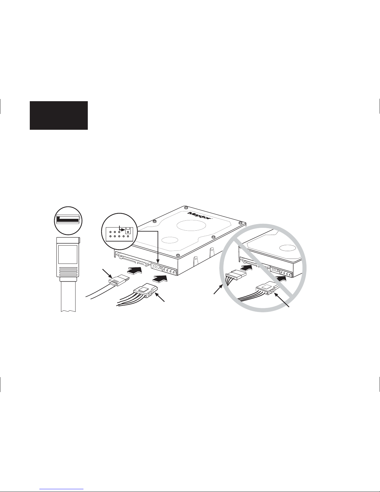
Attach Serial ATA and Power Cables
1.
Locate an available Serial ATA (SATA) port on your motherboard or on a SATA PCI card and plug in one end of the SATA
interface cable.
2.
Locate the SATA port on the rear of the hard drive and plug in the SATA interface cable as shown.
3.
Your Serial ATA drive may be equipped with two power connectors. You can use either the 15 pin SATA or the 4-pin legacy
power connector. These connectors cannot be used at the same time; powering both connectors simultaneously will
damage the drive.
SATA
Do Not
Remove
SATA Interface
Cable
4-pin Legacy
Power Connector
4-pin Legacy
Power Connector
15-pin SATA
Power Connector
Figure 6a
Attaching the Cables to the Hard Drive
Page 11
Attach Serial ATA and Power Cables 8
English
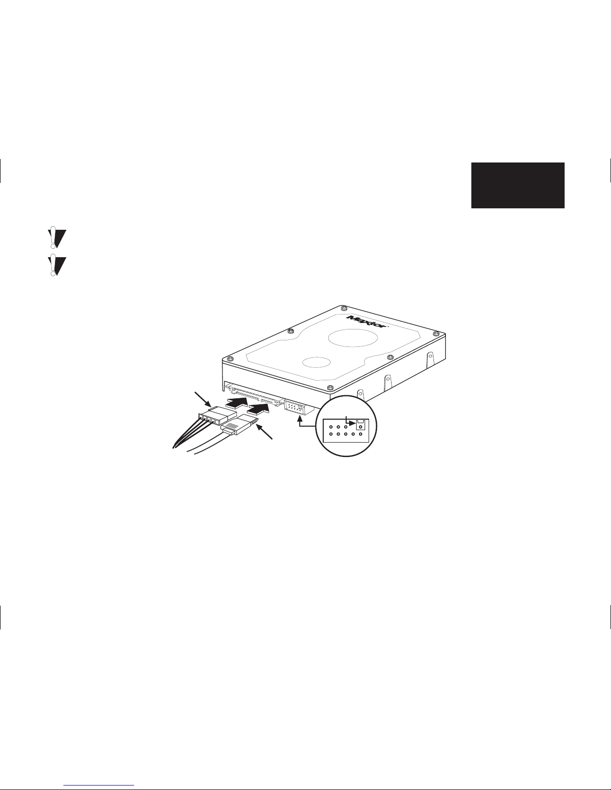
If you have an existing installation of Windows 2000 or XP, you must install a Windows driver for the SATA interface before
connecting the drive. See “Format the Hard Drive” on page 10 for details.
To ensure proper operation of your drive, do not use the jumper pins to the left of the 4-pin power connector (Figure 6a). If
your drive comes with a jumper pre-installed, carefully remove it using needle-nose pliers. If your drive has a single shrouded
jumper pin (see Figure 6a or 6b), please note that the plastic shroud is fixed in place. Do not attempt to remove it.
SATA
Interface Cable
SATA Power
Connector
Do Not
Remove
Figure 6b
Attaching the Cables to the Hard Drive
Page 12
9 Check BIOS Message
English
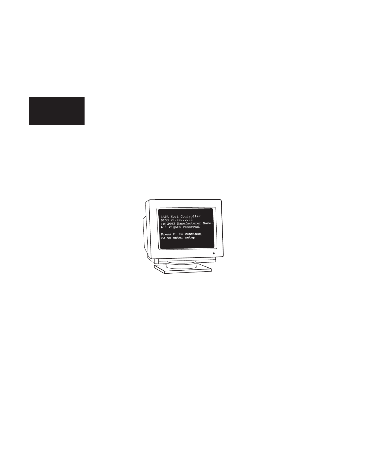
Check BIOS Message
If you have a motherboard with built-in SATA ports , power on your system and look for an on-screen BIOS message that
refers to the SATA interface or controller. (See Figure 7.) This message indicates that the SATA interface on your motherboard
is enabled. If you do not see this message, consult the documentation supplied with your motherboard or system to enable
SATA support in the system BIOS.
If you are using a SATA PCI card , there is no need to enter BIOS Setup to enable SATA support. The card will automatically
enable SATA support after the system BIOS has loaded.
Figure 7
Typical SATA BIOS Message
Page 13
Format the Hard Drive 10
English
Format the Hard Drive
This chapter describes how to partition and format your new drive using the MaxBlast installation software on a Windows
system. Maxtor recommends using MaxBlast on 98 and ME systems, rather than FDISK, to partition and format the drive.
If you have not previously installed a SATA drive in your system, you must install a Windows driver for your SATA PCI card or
SATA-enabled motherboard or system so that Windows can recognize your new drive. For maximum compatibility, Maxtor
recommends downloading and installing the latest SATA driver from the website of the SATA card/motherboard/system
manufacturer. The latest SATA drivers for Maxtor-branded SATA cards can be downloaded from the Worldwide Support section
at www.maxtor.com.
Choose from one of the following installation scenarios:
A. Existing Windows 98 or Me system
B. Existing Windows 2000 or XP system
C. New Windows 98 or Me system or replacing a failed 98 or Me boot drive
D. New Windows 2000 or XP system or replacing a failed 2000 or XP boot drive
Special notes for installation scenarios C and D:
The DOS version of MaxBlast does not currently support USB mouse or keyboard input unless supported by your system BIOS. If you have
a USB keyboard and/or mouse, you may need to connect a PS/2 mouse or keyboard to your system temporarily to navigate through the
program. MaxBlast for DOS can be operated from the keyboard using the Tab, Enter/Return, and arrow keys.
To boot from the MaxBlast CD, you may need to change the boot sequence or boot order settings in your system BIOS to “Floppy
CDROM IDE-0” or “A, CDROM, C.” Depending on your BIOS type (AMI, Award, Phoenix), the boot sequence settings may be located on
the main setup screen or under the BIOS FEATURES SETUP or ADVANCED CMOS SETUP menus.
If your system cannot boot from a CD, you can create a bootable MaxBlast diskette by inserting the MaxBlast CD into a system running
Windows and choosing Create MaxBlast Installation Diskette from the menu. If you have dual optical (CD/DVD) drives, try booting from the
other optical drive..
Page 14

11 Format the Hard Drive
English
A. Existing Windows 98 or Me System
1.
Boot the system into Windows.
2.
The Add New Hardware Wizard will appear informing you that it has found a new PCI mass storage controller. Follow the
SATA card/motherboard/system manufacturer's instructions for installing the driver for the SATA controller.
3.
From the Windows desktop, insert the MaxBlast CD and install MaxBlast for Windows.
4.
Follow the on-screen prompts to step through the installation process. Choose whether to install the drive as additional
storage or as the new boot drive.
5.
Depending on your selection, do one of the following:
a.
Additional storage install: After the drive has been set up as additional storage, double-click the My Computer icon.
A new drive letter and icon should appear. The new drive is ready to use.
b.
Boot drive install: When MaxBlast has finished copying data to your new drive, eject any CDs or floppies and perform a
normal shutdown. Continue to “Set the Boot Sequence (New boot drive only)” on page 15.
Page 15

Format the Hard Drive 12
English
B. Existing Windows 2000 or XP System
The driver for the SATA interface must be installed prior to connecting the hard drive. If you are using a SATA card, you should physically
install it at this time, but do not connect the drive.
1.
Boot the system into Windows.
2.
Follow the SATA card/motherboard/system manufacturer's instructions for installing the SATA driver.
3.
Shut down your system, connect the hard drive, and boot into Windows.
4.
From the Windows desktop, insert the MaxBlast CD and install MaxBlast for Windows.
5.
Follow the on-screen prompts to step through the installation process. Choose whether to install the drive as additional
storage or as the new boot drive.
6.
Depending on your selection, do one of the following:
a.
Additional storage install: After the drive has been set up as additional storage, double-click the My Computer icon.
A new drive letter and icon should appear. The new drive is ready to use.
b.
Boot drive install: When MaxBlast has finished copying data to your new drive, eject any CDs or floppies and perform
a normal shutdown. Continue to “Set the Boot Sequence (New boot drive only)” on page 15.
Page 16

13 Format the Hard Drive
English
C. New Windows 98 or Me System or Replacing a Failed 98 or Me Boot Drive
1.
Boot your system from the MaxBlast CD.
2.
When MaxBlast asks if you would like to prepare the drive for use in your system, click Yes and follow the on-screen
prompts to format and partition your drive.
3.
When finished partitioning and formatting the hard drive, eject all CDs or floppy disks and restart the system.
4.
Boot your system from your Windows system boot floppy.
5.
When prompted to start the computer with CD-ROM support, select this option so that Windows will load the CD-ROM
driver. After the system boot floppy finishes loading, you should see the A:\prompt. Above the prompt, you should also see
a line saying Drive X = Driver MSCD001 unit 0 where X is the drive letter assigned to the CD-ROM drive. Depending on
how many devices are connected to the ATA/IDE cables, the assigned CD-ROM drive letter could be E, F, G, etc.
6.
Note the CD-ROM drive letter, and insert your Windows CD in the CD-ROM drive.
7.
At the A:\ prompt, type X: (where X is the CD-ROM drive letter) and press Enter.
8.
At the X:\ prompt, type SETUP and press Enter. Follow the on-screen instructions to install Windows.
9.
The Windows installer will detect the SATA interface as a PCI mass storage controller near the end of the installation
process. You will need to provide the drivers for the SATA card at this time.
10. Complete the Windows installation process, then continue to “Set the Boot Sequence (New boot drive only)” on page 15.
Page 17

Format the Hard Drive 14
English
D. New Windows 2000 or XP System or Replacing a Failed 2000 or XP Boot Drive
Before you begin. The SATA host driver for motherboards with embedded SATA controllers, or non Maxtor branded SATA hosts, are
typically contained on an installation CD that is included with the motherboard or add-in controller. The SATA host drivers must first be
extracted to a floppy disk before installing the operating system. Drivers for Maxtor-branded SATA cards can be downloaded from the
Worldwide Support section at www.maxtor.com or extracted to floppy from the bootable MaxBlast CD. Boot your system from the
MaxBlast CD.
1.
Boot your system from your Windows installation CD. If you have trouble booting to the Windows XP CD, see Maxtor
Knowledge Base Article #855 at www.maxtor.com.
2.
When prompted by the Windows installer to install a third-party SCSI or RAID driver, press the F6 key then S when
prompted, to specify additional devices.
3.
Insert the SATA driver floppy and press Enter.
4.
Follow the on-screen prompts to finish installing Windows, then continue to “Set the Boot Sequence (New boot drive
only)” on page 15.
Page 18

15 Set the Boot Sequence (New boot drive only)
English
Set the Boot Sequence
(New boot drive only)
The final step is to configure your system BIOS to use your SATA drive as the system boot drive. Your system has a built-in
BIOS Setup utility that allows you to change this setting.
1.
Power on the system and look for an on-screen message indicating which function key to press to enter Setup. (See Figure
7.) The function keys used for entering Setup vary between manufacturers. The most common Setup function keys are F1,
F2, and DEL.
Refer to your system manual for specific information about your system BIOS.
On some newer systems, the function key message for entering Setup disappears before you get a chance to read the screen. Also, some
monitors are slow to display text when powering up the system, so you may need to restart your computer to read the message. To make
it easier to read the function key message, press the Pause/Break key after the memory count to pause the boot process. The Pause/Break
key is usually located in the upper right corner of your keyboard (see Figure 8). Press the Enter key to resume system boot.
2.
Immediately after the function key message appears, press the indicated key to enter Setup.
Within the Setup utility, navigation is limited to keyboard commands. Keyboard instructions are
usually located somewhere on the Setup screen.
3.
Configure the Boot Sequence or Boot Order setting so that the SATA drive or interface is
detected first. This will enable the SATA drive to be used as the boot drive.
On some newer systems, you may be able to set the boot order of individual SATA drives in BIOS Setup.
4.
Save the settings, exit Setup, and reboot your system.
Figure 8
Pause/Break Key
on a Keyboard
Page 19

Getting Help 16
English
Getting Help
Before contacting Maxtor Support, use the Hard Disk Information feature in MaxBlast to view the model number and serial
number of your drive. These numbers can be used to get help from Maxtor Support, register your drive, and look up information
on the Maxtor website.
Please visit www.maxtor.com to obtain comprehensive support information, such as:
• Warranty Services
Drive Returns (RMA), Warranty Status, Limited Warranty Statement
• Product Support
Installation Tutorial, Specifications, Jumper Settings, Installation Guides, Product Manuals
• Software Downloads
Installation Software, Utilities, Diagnostics
• Knowledge Base
Troubleshooting information, FAQs, resolved problem database
• Product Index
Current and Legacy Maxtor product's listing
Click on Support to access the Knowledge Base, download software updates, register your drive, and get assistance via e-mail.
Page 20

17 Getting Help
English
Page 21

Français
Contenu
Informations de garantie
. . . . . . . . . . . . . . . . . . . . . . . . . . . . . . . . . . . . . . . 19
Introduction
. . . . . . . . . . . . . . . . . . . . . . . . . . . . . . . . . . . . . . . . . . . . . . . . . . . 20
Précautions . . . . . . . . . . . . . . . . . . . . . . . . . . . . . . . . . . . . . . . . . . . . . . . . . . . . 20
Contenu du kit. . . . . . . . . . . . . . . . . . . . . . . . . . . . . . . . . . . . . . . . . . . . . . . . . . 20
Outils requis . . . . . . . . . . . . . . . . . . . . . . . . . . . . . . . . . . . . . . . . . . . . . . . . . . . 21
A propos de la technologie Serial ATA . . . . . . . . . . . . . . . . . . . . . . . . . . . . . . . 21
Sauvegarde des données . . . . . . . . . . . . . . . . . . . . . . . . . . . . . . . . . . . . . . . . . 21
Installation du disque dur sur un système Macintosh. . . . . . . . . . . . . . . . . . . . 21
Retrait du capot du système
. . . . . . . . . . . . . . . . . . . . . . . . . . . . . . . . . . . . 22
Montage du disque dur
. . . . . . . . . . . . . . . . . . . . . . . . . . . . . . . . . . . . . . . . . 23
Connexion des câbles d'alimentation et Serial ATA
. . . . . . . . . . . . . . 25
Vérification du message du BIOS
. . . . . . . . . . . . . . . . . . . . . . . . . . . . . . . 27
Formatage du disque dur
. . . . . . . . . . . . . . . . . . . . . . . . . . . . . . . . . . . . . . . 28
Définition de la séquence de démarrage
. . . . . . . . . . . . . . . . . . . . . . . . 33
Obtention d’aide
. . . . . . . . . . . . . . . . . . . . . . . . . . . . . . . . . . . . . . . . . . . . . . . 34
Page 22

19 Informations de garantie
Français
Informations de garantie
Avant d’installer le disque dur, prenez soin de noter le numéro de série composé de 8 caractères ainsi que le numéro
de référence à 14 chiffres. Si vous devez un jour contacter le support de Maxtor, les opérateurs vous demanderont ces
informations sur le disque dur afin de pouvoir vous apporter de l’aide.
Plusieurs modèles de disques durs sont illustrés ci-dessous pour vous permettre d’identifier l’emplacement de ces numéros.
Choisissez l'illustration qui correspond à votre disque dur, puis localisez les numéros de série et de référence de votre disque
et notez-les dans l’espace prévu à cet effet.
Numéro de référence (Réf.)
Numéro de série
Numéro de référence
Numéro de série
Numéro de référence
Numéro de série
Numéro de référence
Numéro de série
Page 23

Introduction 20
Français
Introduction
Merci d'avoir choisi un disque dur de Maxtor. Ce manuel vous guidera tout au
long de l'installation de votre nouveau disque.
Si vous rencontrez une quelconque difficulté au cours de la procédure
d'installation, visitez notre site Web à l'adresse
www.maxtor.com
et cliquez sur
Support international.
Le kit du disque dur SATA de Maxtor comprend les accessoires présentés dans
l'illustration 1. Selon votre ordinateur, vous aurez besoin de tout ou partie de ces
accessoires pour effectuer l'installation. Vous aurez également besoin des outils
indiqués à l’illustration 2, page 21, pour installer le disque dur sur votre ordinateur.
Précautions
Attendez que le disque ait atteint la température ambiante
pour commencer l'installation.
Ne touchez pas au circuit imprimé du disque.
Débranchez le système de la prise électrique avant de
connecter les câbles au disque ou à la carte mère.
Ne faites subir aucun choc au disque ; ne le laissez pas tomber.
Câble d'interface
SATA
Le présent guide
d'installation
CD-ROM
MaxBlast
®
Vis de montage
Max•Blast
™
Disque dur Serial
ATA (SATA) de
Maxtor
Illustration 1
Éléments compris dans le kit
Page 24

21 Introduction
Français
A propos de la technologie Serial ATA
La technologie Serial ATA (SATA) offre les avantages suivants :
• Interface ATA la plus rapide qui soit
• Idéale pour des agrégats RAID haute performance
• Câbles fins, faciles à brancher, garantissant une meilleure circulation de l'air
• Pas de cavalier à configurer, ce qui facilite l'installation
Contrairement aux lecteurs ATA standard, les lecteurs Serial ATA ne nécessitent
pas l'utilisation de cavaliers de configuration.
Visitez notre site Web à l'adresse www.maxtor.com et cliquez sur Support
international pour connaître les dernières informations relatives à la technologie
SATA, ainsi que les mises à jour logicielles disponibles.
Sauvegarde des données
Pour protéger vos données, effectuez une sauvegarde du contenu des disques
durs existants avant d'installer votre nouveau disque dur Maxtor.
Installation du disque dur sur un système Macintosh
Pour plus d'informations sur le montage d'un disque dur interne dans votre
système Macintosh, visitez le site Web www.apple.com/support. Une fois que
le disque est monté, vous pouvez le formater (initialiser) et le partitionner à l'aide
de l'utilitaire Apple Drive Setup (pour les systèmes Mac OS 8.6 ou ultérieurs) ou
Apple Disk (pour les systèmes Mac OS X). Notez que sur tous les systèmes
beiges Power Mac G3 (bureau, mini-tour et compact), Mac OS X ne peut être
installé que sur une partition occupant les 8 premiers Go du disque.
System
M
anual
Manuel de l'utilisateur
du système
CD-ROM du système
d'exploitation et disquette
de démarrage
Tournevis cruciforme
Petite pince plate
Illustration 2
Outils requis
Page 25

Retrait du capot du système 22
Français
Retrait du capot du système
1.
Mettez le système hors tension.
2.
Débranchez le système de la prise électrique.
3.
Enlevez le capot de votre système. Reportez-vous à l’illustration 3.
4. Portez un bracelet antistatique ou touchez une partie métallique du boîtier de l'ordinateur. Ce faisant,
vous vous déchargez de l'électricité statique que vous portez en vous et évitez ainsi d'exposer le disque
dur à des décharges électrostatiques.
Illustration 3
Retrait du capot du système
Reportez-vous au manuel de
l'utilisateur du système pour
savoir comment retirer le capot
ou faites appel à un technicien
qualifié pour ce type
d'opération.
Page 26

23 Montage du disque dur
Français
Montage du disque dur
Avant de monter le disque dur sur votre système, déterminez s'il faut l'installer dans une baie de 3 pouces 1/2 ou
de 5 pouces 1/4. Si vous ne parvenez pas à localiser une baie de montage disponible, consultez le manuel de l'utilisateur
ou le fabricant du système.
Installation dans une baie de montage de 3 pouces 1/2
Un grand nombre de systèmes comportent une baie de 3 pouces 1/2 disponible à côté du lecteur de disquette.
• Montez le disque dur dans la baie de 3 pouces 1/2 à l'aide des vis fournies. Reportez-vous à l’illustration 4.
Mounting
Screws
Vis de
montage
Il est possible qu'il manque de la
place sur certains systèmes pour
brancher les câbles après le
montage du disque dur.
Commencez alors par connecter
les câbles d'alimentation et SATA.
Illustration 4
Installation dans une baie de montage de 3 pouces 1/2
Page 27

Montage du disque dur 24
Français
Installation dans une baie de montage de 5 pouces 1/4
Lorsque vous installez le disque dur dans une baie de 5 pouces 1/4 (telle que celle où l'on installe généralement un lecteur de
CD-ROM), vous devez d'abord fixer les supports de montage (non fournis) au disque dur. Vous pouvez vous procurer des
supports de montage dans tout magasin de consommables informatiques.
1.
Fixez les supports de montage au disque dur à l'aide des vis fournies avec ce kit. Reportez-vous à l’illustration 5 pour plus
d'informations.
2.
Installez le disque dur dans la baie de 5 pouces 1/4 à l'aide des vis fournies avec les supports de montage. Positionnez le
disque dur aussi près que possible de la partie inférieure de la baie, étiquette vers le haut.
Illustration 5
Fixation des supports de montage au disque dur
Page 28

25 Connexion des câbles d'alimentation et Serial ATA
Français
Connexion des câbles d'alimentation et Serial ATA
1.
Localisez un port Serial ATA (SATA) disponible sur la carte mère ou sur une carte PCI SATA et branchez une extrémité
du câble d'interface SATA.
2.
Localisez le port SATA à l'arrière du disque dur et branchez le câble d'interface SATA comme indiqué.
3.
Votre disque Serial ATA comporte deux connecteurs d’alimentation. Utilisez le connecteur d’alimentation SATA à 15
broches ou le connecteur d'alimentation traditionnel à 4 broches. N'utilisez pas ces deux connecteurs simultanément ; vous
risqueriez d'endommager le lecteur.
SATA
Ne pas
supprimer
Câble d'interface
SATA
Connecteur d’alimentation
traditionnel à 4 broches
Connecteur
d’alimentation SATA
à 15 broches
Connecteur d’alimentation
traditionnel à 4 broches
Illustration 6a
Connexion des câbles au disque dur
Page 29

Connexion des câbles d'alimentation et Serial ATA 26
Français
Si le système d'exploitation Windows 2000 ou XP est installé sur votre système, vous devez installer un pilote Windows
pour l'interface SATA avant de connecter le lecteur. Reportez-vous à la section “Formatage du disque dur” pour plus
d'informations.
Pour assurer le bon fonctionnement de votre disque, n'utilisez pas les broches du cavalier situées à gauche du connecteur
d'alimentation à 4 broches (voir l’illustration 6a). Si un cavalier est déjà installé sur votre disque, retirez-le délicatement à l'aide
d'une pince plate. Si une seule broche de cavalier de votre disque est recouverte (voir l’illustration 6a ou 6b), notez que la
protection plastique doit rester en place. N'essayez pas de l'enlever.
Câble d'interface
SATA
Connecteur
d’alimentation
SATA
Ne pas
supprimer
Illustration 6b
Connexion des câbles au disque dur
Page 30

27 Vérification du message du BIOS
Français
Vérification du message du BIOS
Si votre carte mère comporte des ports SATA intégrés , mettez votre système sous tension et attendez l'affichage d'un
message du BIOS se rapportant au contrôleur ou à l'interface SATA (reportez-vous à l’illustration 7). Ce message indique que
l'interface SATA est activée sur votre carte mère. Si ce message ne s'affiche pas, consultez la documentation fournie avec
votre carte mère ou votre système pour activer la prise en charge de SATA dans le BIOS système.
Si vous utilisez une carte PCI SATA , il n'est pas nécessaire d'accéder au programme de configuration du BIOS pour activer la
prise en charge de SATA. En effet, la carte active automatiquement la prise en charge de SATA à l'issue du chargement du
BIOS système.
Illustration 7
Message type du BIOS SATA
Page 31

Formatage du disque dur 28
Français
Formatage du disque dur
Ce chapitre explique comment partitionner et formater votre nouveau disque à l'aide du logiciel d’installation MaxBlast sur un
système Windows. Maxtor recommande d’employer MaxBlast plutôt que l'utilitaire FDISK avec les systèmes d’exploitation 98
et ME pour procéder au partitionnement et au formatage du disque.
Si vous n'avez pas encore installé de disque SATA dans votre système, vous devez installer un pilote Windows pour votre carte
PCI SATA, ou un système ou encore une carte mère avec prise en charge SATA, afin que Windows puisse reconnaître le
nouveau disque. Afin de garantir une compatibilité maximale, Maxtor recommande de télécharger et d'installer le dernier pilote
SATA disponible à partir du site Web du fabricant de la carte SATA, de la carte mère ou du système. Il est possible de
télécharger les derniers pilotes SATA disponibles pour les cartes SATA de marque Maxtor à partir de la section Support
international du site Web www.maxtor.com.
Choisissez l'une des options d'installation suivantes :
A. Système Windows 98 ou Me existant
B. Système Windows 2000 ou XP existant
C. Nouveau système Windows 98 ou Me ou remplacement d'un disque de démarrage 98 ou Me défectueux
D. Nouveau système Windows 2000 ou XP ou remplacement d'un disque de démarrage 2000 ou XP défectueux
Remarques spéciales concernant les options d'installation C et D :
Actuellement, la version DOS de MaxBlast ne prend pas en charge les claviers ou souris USB, sauf s'ils sont reconnus par le BIOS du
système. Si vous disposez d'un clavier et/ou d'une souris USB, il est possible que vous deviez temporairement connecter un clavier ou une
souris PS/2 à votre système pour pouvoir naviguer au sein du programme. La version DOS de MaxBlast peut être pilotée depuis le clavier
à l'aide des touches Tab, Entrée/Retour et des touches fléchées.
Pour démarrer depuis le CD-ROM MaxBlast, vous devrez peut-être modifier la séquence de démarrage ou les paramètres d'ordre de
démarrage dans le BIOS de votre système comme suit : “Disquette CD-ROM IDE-0” ou “A, CD-ROM, C”. Selon le type de BIOS (AMI,
Award, Phoenix), les paramètres de séquence de démarrage peuvent se trouver dans l'écran de configuration principal ou dans l'un des
menus de CONFIGURATION DES FONCTIONS DU BIOS ou CONFIGURATION CMOS AVANCÉE.
Si votre système ne parvient pas à démarrer depuis un CD-ROM, vous avez la possibilité de créer une disquette de démarrage MaxBlast en
insérant le CD-ROM MaxBlast dans un système tournant sous Windows et en choisissant l'option de création d'une disquette d'installation
MaxBlast dans le menu. Si vous avez deux disques optiques (lecteurs de CD-ROM/DVD), essayez de démarrer le système à partir de l'autre
disque optique.
Page 32

29 Formatage du disque dur
Français
A. Système Windows 98 ou Me existant
1. Démarrez le système sous Windows.
2.
L'assistant Ajout de nouveau matériel apparaît, vous informant qu'il a trouvé un nouveau contrôleur de stockage de masse
PCI. Suivez les instructions fournies par le fabricant de la carte SATA, de la carte mère ou du système pour installer le pilote
du contrôleur SATA.
3.
Depuis le bureau de Windows, insérez le CD-ROM de MaxBlast et installez MaxBlast pour Windows.
4.
Suivez les messages affichés à l'écran pour procéder à l'installation. Choisissez d'installer le disque comme périphérique
de stockage supplémentaire ou comme nouveau disque de démarrage.
5.
En fonction de votre choix, effectuez l'une des opérations suivantes :
a.
Installation comme périphérique de stockage supplémentaire : une fois que le disque dur a été configuré comme
périphérique de stockage supplémentaire, double-cliquez sur l'icône Poste de travail. Une nouvelle lettre d'unité
et une icône doivent s'afficher. Le nouveau disque est opérationnel.
b.
Installation comme disque de démarrage : lorsque MaxBlast a fini de copier les données sur votre nouveau lecteur,
retirez tous les CD-ROM ou les disquettes et arrêtez le système selon la procédure normale. Passez à l'étape décrite
à la section “Définition de la séquence de démarrage (nouveau disque de démarrage uniquement)” à la page 33.
Page 33

Formatage du disque dur 30
Français
B. Système Windows 2000 ou XP existant
Le pilote de l'interface SATA doit être installé avant la connexion du disque dur. Si vous utilisez une carte SATA, vous devez l'installer
physiquement maintenant, mais sans connecter le lecteur.
1.
Démarrez le système sous Windows.
2.
Suivez les instructions fournies par le fabricant de la carte SATA, de la carte mère ou du système pour installer le pilote SATA.
3.
Arrêtez le système, connectez le disque dur et démarrez sous Windows.
4.
Depuis le bureau de Windows, insérez le CD-ROM de MaxBlast et installez MaxBlast pour Windows.
5.
Suivez les messages affichés à l'écran pour procéder à l'installation. Choisissez d'installer le disque comme périphérique de
stockage supplémentaire ou comme nouveau disque de démarrage.
6.
En fonction de votre choix, effectuez l'une des opérations suivantes :
a.
Installation comme périphérique de stockage supplémentaire : une fois que le disque dur a été configuré comme
périphérique de stockage supplémentaire, double-cliquez sur l'icône Poste de travail. Une nouvelle lettre d'unité et une
icône doivent s'afficher. Le nouveau disque est opérationnel.
b.
Installation comme disque de démarrage : lorsque MaxBlast a fini de copier les données sur votre nouveau lecteur,
retirez tous les CD-ROM ou les disquettes et arrêtez le système selon la procédure normale. Passez à l'étape décrite à
la section “Définition de la séquence de démarrage (nouveau disque de démarrage uniquement)” à la page 33.
Page 34

31 Formatage du disque dur
Français
C. Nouveau système Windows 98 ou Me ou remplacement d'un disque de démarrage 98 ou Me défectueux
1. Démarrez votre système à partir du CD-ROM de MaxBlast.
2.
Lorsque MaxBlast vous demande si vous voulez préparer le disque dur en vue d'une utilisation sur votre système, cliquez
sur Oui et suivez les messages affichés à l'écran pour formater et partitionner votre disque.
3.
A l'issue du partitionnement et du formatage du disque dur, éjectez tous les CD-ROM ou les disquettes et redémarrez le
système.
4.
Démarrez votre système à partir de la disquette de démarrage du système Windows.
5.
Lorsque vous êtes invité à démarrer l'ordinateur par CD-ROM, sélectionnez cette option afin que Windows charge le pilote
du lecteur de CD-ROM. Une fois que le chargement de la disquette de démarrage système est terminé, l'invite A:\ doit
s'afficher. Une ligne doit également s'afficher au-dessus de l'invite, portant le message “Drive X = Driver MSCD001 unit
0”, où X désigne la lettre du lecteur affectée au lecteur de CD-ROM. Selon le nombre de périphériques connectés aux
câbles ATA/IDE, la lettre affectée au lecteur de CD-ROM peut être E, F, G, etc.
6.
Notez la lettre du lecteur de CD-ROM et insérez le CD-ROM Windows dans le lecteur de CD-ROM.
7.
A l'invite A:\, tapez X: (où X représente la lettre du lecteur de CD-ROM) et appuyez sur la touche Entrée.
8.
A l'invite X:\, tapez SETUP et appuyez sur la touche Entrée. Suivez les instructions affichées à l'écran pour installer
Windows.
9.
Le programme d'installation de Windows détecte alors l'interface SATA en tant que contrôleur de stockage de masse PCI
vers la fin du processus d'installation. C'est à ce stade que vous devrez fournir les pilotes pour la carte SATA.
10. Terminez l'installation de Windows, puis passez à l'étape décrite à la section “Définition de la séquence de démarrage
(nouveau disque de démarrage uniquement)” à la page 33.
Page 35

Formatage du disque dur 32
Français
D. Nouveau système Windows 2000 ou XP ou remplacement d'un disque de démarrage 2000 ou XP défectueux
Avant de commencer : le pilote hôte SATA pour les cartes mères disposant de contrôleurs SATA intégrés, ou d’hôtes SATA de marque autre
que Maxtor, figure généralement sur un CD-ROM d’installation fourni avec la carte mère ou le contrôleur d’ajout. Les pilotes hôtes SATA
doivent être chargés sur une disquette avant d’être installés sur le système d’exploitation. Les pilotes des cartes SATA de marque Maxtor
peuvent être téléchargés à partir de la section Support international du site Web www.maxtor.com ou chargés sur une disquette de
démarrage à partir du CD-ROM MaxBlast. Démarrez votre système à partir du CD-ROM de MaxBlast.
1.
Démarrez votre système à partir du CD-ROM d'installation de Windows. Si vous rencontrez des problèmes pour démarrer
depuis le CD-ROM Windows XP, lisez l'article de la base de connaissances Maxtor numéro 855 sur le site Web
www.maxtor.com.
2.
Lorsque vous êtes invité par le programme d'installation de Windows à installer un pilote RAID ou SCSI d'un fabricant tiers,
appuyez sur la touche F6, puis sur S afin de spécifier des périphériques supplémentaires.
3.
Insérez la disquette du pilote SATA et appuyez sur la touche Entrée.
4.
Suivez les instructions à l’écran pour terminer l'installation de Windows, puis passez à l'étape décrite à la section
“Définition de la séquence de démarrage (nouveau disque de démarrage uniquement)” à la page 33.
Page 36

33 Définition de la séquence de démarrage (nouveau disque de démarrage uniquement)
Français
Définition de la séquence de démarrage
(nouveau disque de démarrage uniquement)
La dernière étape consiste à configurer le BIOS du système afin que votre lecteur SATA soit utilisé comme disque de démarrage
du système. Votre système dispose d'un utilitaire de configuration du BIOS intégré qui vous permet de modifier ce paramètre.
1.
Mettez le système sous tension et attendez l'affichage d'un message vous invitant à appuyer sur une touche de fonction
pour accéder au programme de configuration (reportez-vous à l’illustration 7). Selon les fabricants, les touches de fonction
utilisées pour accéder au programme de configuration peuvent varier. Les touches de fonction de configuration les plus
courantes sont F1, F2 et SUPPR.
Reportez-vous au manuel du système pour obtenir des informations spécifiques au BIOS de votre système.
Sur les systèmes plus récents, le message indiquant la touche de fonction pour accéder au programme de configuration disparaît avant
même que vous ayez eu le temps de l'apercevoir à l'écran. Comme certains moniteurs affichent le texte plus lentement lors de la mise
sous tension du système, il vous faudra peut-être redémarrer l'ordinateur pour lire le message. Pour lire le message de la touche de
fonction plus facilement, appuyez sur la touche Pause/Attn une fois la capacité mémoire totale affichée afin de marquer une pause dans le
processus de démarrage. Cette touche se situe généralement dans l'angle supérieur droit de votre clavier (voir Illustration 8). Appuyez sur
la touche Entrée pour reprendre le démarrage du système.
2.
Dès l'apparition du message de la touche de fonction, appuyez sur la touche indiquée pour
accéder au programme de configuration. Au sein de l'utilitaire de configuration, la navigation se
fait uniquement à l'aide des commandes du clavier. Des instructions relatives à l'emploi des
touches du clavier sont généralement présentes dans l'écran de configuration.
3.
Définissez la séquence de démarrage ou les paramètres d'ordre de démarrage de sorte que
l'interface ou le disque SATA soit détecté en premier. Cela permettra au disque SATA d'être
utilisé comme disque de démarrage.
Sur certains systèmes plus récents, vous pourrez éventuellement définir l'ordre de démarrage de lecteurs
SATA individuels dans le programme de configuration du BIOS.
4.
Enregistrez les paramètres, quittez l'utilitaire de configuration et redémarrez le système.
Illustration 8
Touche Pause/Attn d'un
clavier
Page 37

Obtention d'aide 34
Français
Obtention d'aide
Avant de contacter le support Maxtor, utilisez la fonction d’informations sur le disque dur de MaxBlast pour afficher les
numéros de modèle et de série de votre disque. Ces numéros vous permettent d’obtenir de l’aide auprès du support Maxtor,
d’enregistrer votre disque et de rechercher des informations sur le site Web de Maxtor.
Consultez notre site Web à l’adresse www.maxtor.com pour obtenir des informations complètes sur le support, notamment :
• Services de garantie
Retour de disques durs (RMA), état de la garantie, déclaration de garantie limitée
• Support produit
Didacticiel d’installation, caractéristiques, paramètres des cavaliers, guides d’installation, manuels sur les produits
• Téléchargements logiciels
Logiciels d'installation, utilitaires, outils de diagnostic
• Base de connaissances
Informations de dépannage, FAQ, base de données de solutions de problèmes
• Index des produits
Liste des anciens et nouveaux produits Maxtor
Cliquez sur Support pour accéder à la base de connaissances, télécharger des mises à jour de logiciels, enregistrer votre produit
et obtenir de l'assistance par e-mail.
Page 38

35 Obtention d'aide
Français
Page laissée intentionnellement blanche
Page 39

Deutsch
Inhalt
Garantie-Registrierungsinformationen
. . . . . . . . . . . . . . . . . . . . . . . . . . 37
Einleitung
. . . . . . . . . . . . . . . . . . . . . . . . . . . . . . . . . . . . . . . . . . . . . . . . . . . . . . 38
Vorsichtsmaßnahmen . . . . . . . . . . . . . . . . . . . . . . . . . . . . . . . . . . . . . . . . . . . . 38
Inhalt dieses Kits . . . . . . . . . . . . . . . . . . . . . . . . . . . . . . . . . . . . . . . . . . . . . . . . 38
Benötigte Werkzeuge . . . . . . . . . . . . . . . . . . . . . . . . . . . . . . . . . . . . . . . . . . . . 39
Über serielles ATA . . . . . . . . . . . . . . . . . . . . . . . . . . . . . . . . . . . . . . . . . . . . . . 39
Sichern Sie Ihre Daten . . . . . . . . . . . . . . . . . . . . . . . . . . . . . . . . . . . . . . . . . . . 39
Installation der Festplatte in einem Macintosh-Computer . . . . . . . . . . . . . . . . 39
Entfernen der Systemabdeckung
. . . . . . . . . . . . . . . . . . . . . . . . . . . . . . . 40
Einbau der Festplatte
. . . . . . . . . . . . . . . . . . . . . . . . . . . . . . . . . . . . . . . . . . 41
Anschließen der seriellen ATA- und Netzkabel
. . . . . . . . . . . . . . . . . . 43
Überprüfen der BIOS-Anzeige
. . . . . . . . . . . . . . . . . . . . . . . . . . . . . . . . . . 45
Formatieren der Festplatte
. . . . . . . . . . . . . . . . . . . . . . . . . . . . . . . . . . . . . 46
Einstellen der Bootreihenfolge
. . . . . . . . . . . . . . . . . . . . . . . . . . . . . . . . . . 51
Hilfe
. . . . . . . . . . . . . . . . . . . . . . . . . . . . . . . . . . . . . . . . . . . . . . . . . . . . . . . . . . . 52
Page 40

37 Garantie-Registrierungsinformationen
Deutsch
Garantie-Registrierungsinformationen
Notieren Sie sich bitte vor dem Einbau der Festplatte die achtstellige Seriennummer und die vierzehnstellige Artikelnummer.
Diese Identifikationsnummern Ihrer Festplatte sind bei jeder diesbezüglichen Kontaktaufnahme mit dem Maxtor Support
anzugeben.
Nachfolgend sehen Sie Abbildungen verschiedener Festplattenmodelle, die Ihnen helfen sollen, diese Nummern auf der
Festplatte zu lokalisieren. Vergleichen Sie Ihre Festplatte mit den Abbildungen und suchen Sie die Artikel- und Seriennummer.
Notieren Sie diese anschließend in den dafür vorgesehenen Feldern.
Artikelnummer (P/N) Seriennummer (S/N)
Artikelnummer
Seriennummer
Artikelnummer
Seriennummer
Artikelnummer
Seriennummer
Page 41

Einleitung 38
Deutsch
Einleitung
Vielen Dank, dass Sie sich für eine Festplatte von Maxtor entschieden haben.
Diese Anleitung führt Sie durch den Installationsprozess Ihrer Festplatte.
Bitte besuchen Sie unsere Website
www.maxtor.com
und klicken Sie auf
Worldwide Support, falls Sie Schwierigkeiten bei der Installation haben sollten.
Das Maxtor SATA-Festplattenkit setzt sich aus den in Abbildung 1 dargestellten
Bestandteilen zusammen. Je nach Computer benötigen Sie alle oder nur
bestimmte Teile, um die Installation durchzuführen. Sie werden zudem die in
Abbildung 2 auf Seite 39 dargestellten Werkzeuge benötigen, um die Festplatte
in Ihrem Computer zu installieren.
Vorsichtsmaßnahmen
Die Festplatte sollte beim Einbau Zimmertemperatur haben.
Berühren Sie auf keinen Fall die Platine auf der Festplatte.
Ziehen Sie den Netzstecker aus der Steckdose, bevor Sie die Kabel an die Festplatte
bzw. an das Motherboard anschließen.
Lassen Sie die Festplatte niemals fallen und setzen Sie diese keinen Schlägen oder
Erschütterungen aus.
SATA-
Schnittstellenkabel
Diese
Installationsanleitung
MaxBlast
®
CD-ROM
Einbauschrauben
Max•Blast
™
Maxtors serielle
ATA (SATA)-
Festplatte
Abbildung 1
Inhalt dieses Kits
Page 42

39 Einleitung
Deutsch
Über serielles ATA
Die serielle ATA (SATA)-Technologie bietet Ihnen folgende Vorteile:
• Schnellste ATA-Schnittstelle der Welt
• Ideal für Hochgeschwindigkeits-RAID
• Dünne, einfach anzuschließende Kabel für verbesserte Luftzirkulation
• Einfache Installation ohne Jumper
Anders als bei Standard-ATA-Festplatten werden zur Konfiguration von seriellen
ATA-Festplatten keine Jumper benötigt.
Aktuelle Informationen über SATA sowie Software-Updates finden Sie auf
www.maxtor.com unter Worldwide Support.
Sichern Sie Ihre Daten
Schützen Sie die Daten Ihrer anderen Festplatten, indem Sie vor der Installation
der neuen Festplatte Sicherungskopien aller Daten anlegen.
Installation der Festplatte in einem Macintosh-Computer
Ausführliche Informationen zum Einbau einer internen Festplatte in Ihren Macintosh
erhalten Sie unter www.apple.com/support. Nach Einbau der Festplatte können Sie
diese mit dem Setup-Dienstprogramm (bei Mac OS 8.6 oder höher) oder dem
Festplattendienstprogramm (bei Mac OS X) von Apple formatieren (initialisieren) und
partitionieren. Beachten Sie, dass bei allen beigefarbenen Power Mac G3-Systemen
(Desktop, Minitower, Komplettsysteme), Mac OS X nur auf einer Partition installiert
werden kann, die innerhalb der ersten 8 GB der Festplatte angelegt ist.
System
M
anual
Systemhandbuch
Betriebssystem-
CD-ROM und Startdiskette
Kreuzschlitz-Schraubenzieher
Eine kleine Spitzzange
Abbildung 2
Benötigte Werkzeuge
Page 43

Entfernen der Systemabdeckung 40
Deutsch
Entfernen der Systemabdeckung
1.
Schalten Sie Ihren Computer aus.
2.
Ziehen Sie den Netzstecker aus der Steckdose.
3.
Entfernen Sie die Systemabdeckung. Siehe Abbildung 3.
4. Verwenden Sie ein Masseband oder berühren Sie ein Metallteil an Ihrem Computergehäuse. Dadurch werden Sie geerdet
und das Risiko, die Festplatte elektrostatischer Entladung auszusetzen, wird verringert.
Abbildung 3
Entfernen der Systemabdeckung
Informationen zum Entfernen
der Abdeckung finden Sie in
Ihrem Systemhandbuch. Sie
können sich aber auch an einen
qualifizierten Installationstechniker wenden.
Page 44

41 Einbau der Festplatte
Deutsch
Einbau der Festplatte
Entscheiden Sie vor dem Einbau, ob Sie die Festplatte in einen 3,5-Zoll- oder in einen 5,25-Zoll-Geräteschacht einbauen wollen.
Konsultieren Sie Ihr Systemhandbuch oder wenden Sie sich an den Systemhersteller, wenn Sie keinen freien Geräteschacht
finden können.
Einbau in einen 3,5-Zoll-Geräteschacht
Bei vielen Systemen befindet sich der 3,5-Zoll-Geräteschacht direkt im Anschluss an das Diskettenlaufwerk.
• Befestigen Sie die Festplatte mit den mitgelieferten Schrauben im 3,5-Zoll-Geräteschacht. Siehe Abbildung 4.
Mounting
Screws
Einbau-
schrauben
Es könnte sein, dass bei einigen
Geräten nach Einbau der Festplatte nicht ausreichend Platz
vorhanden ist, um die Kabel
anzuschließen. Es ist eventuell
erforderlich, die SATA- und
Netzkabel zuerst anzuschließen.
Abbildung 4
Typischer Einbau in einen 3,5-Zoll-Geräteschacht
Page 45

Einbau der Festplatte 42
Deutsch
Einbau in einen 5,25-Zoll-Geräteschacht
Wenn Sie die Festplatte in einen 5,25-Zoll-Schacht einbauen (dort, wo normalerweise CD-ROM-Laufwerke installiert sind),
müssen Sie zuerst Einbauschienen (nicht enthalten) an der Festplatte befestigen. Diese können Sie von einem
Computerhändler in Ihrer Nähe beziehen.
1.
Mit den Schrauben aus diesem Kit befestigen Sie die Einbauschienen an der Festplatte. Siehe Abbildung 5 für Details.
2.
Befestigen Sie die Festplatte mit den bei den Einbauschienen mitgelieferten Schrauben im 5,25-Zoll-Geräteschacht. Bauen
Sie die Festplatte so weit unten wie möglich im Geräteschacht ein. Der Festplattenaufkleber sollte wenn möglich nach
oben zeigen.
Abbildung 5
Befestigen der Einbauschienen an der Festplatte
Page 46

43 Anschließen der seriellen ATA- und Netzkabel
Deutsch
Anschließen der seriellen ATA- und Netzkabel
1.
Lokalisieren Sie einen freien seriellen ATA (SATA)-Anschluss auf Ihrem Motherboard oder auf einer SATA PCI-Karte und
schließen Sie ein Ende des SATA-Schnittstellenkabels daran an.
2.
Lokalisieren Sie den SATA-Anschluss auf der Rückseite der Festplatte und schließen Sie daran das andere Ende des SATASchnittstellenkabels wie gezeigt an.
3.
Ihre serielle ATA-Festplatte ist mit bis zu zwei Stromanschlüssen ausgestattet. Entweder Sie verwenden den 15-Stift-SATAStromanschluss oder den herkömmlichen 4-Stift-Stromanschluss. Diese Anschlüsse können nicht gleichzeitig genutzt
werden, da dies zur Beschädigung der Festplatte führen würde.
SATA
Nicht
entfernen
SATA-
Schnittstellenkabel
Herkömmlicher 4-Stift-
Stromanschluss
Herkömmlicher 4-Stift-
Stromanschluss
15-Stift-SATA-
Stromanschluss
Abbildung 6a
Anschließen der Kabel an der Festplatte
Page 47

Anschließen der seriellen ATA- und Netzkabel 44
Deutsch
Wenn Windows 2000 oder XP auf Ihrem System installiert ist, muss vor dem Anschluss der Festplatte ein Windows-Treiber
für die SATA-Schnittstelle installiert werden. Einzelheiten hierzu finden Sie unter „Formatieren der Festplatte“ auf Seite 46.
Für den fehlerfreien Betrieb Ihrer Festplatte sollten die Jumperstifte links neben dem 4-Stift-Stromanschluss nicht benutzt
werden (Abbildung 6a). Sollte auf Ihrer Festplatte ein Jumper gesetzt sein, entfernen Sie diesen bitte vorsichtig mit der
Spitzzange. Ist bei Ihrer Festplatte an dieser Stelle ein einzelner abgedeckter Jumperstift installiert (siehe Abbildung 6a oder 6b),
sollten Sie sicherstellen, dass die Plastikabdeckung fest verankert ist. Versuchen Sie nicht, sie zu entfernen.
SATA-
Schnittstellenkabel
15-Stift-SATA-
Stromanschluss
Nicht
entfernen
Abbildung 6b
Anschließen der Kabel an der Festplatte
Page 48

45 Überprüfen der BIOS-Anzeige
Deutsch
Überprüfen der BIOS-Anzeige
Wenn Ihr Motherboard über eingebaute SATA-Anschlüsse verfügt , schalten Sie Ihr System ein und achten Sie auf eine
BIOS-Meldung bezüglich der SATA-Schnittstelle oder dem SATA-Controller (siehe Abbildung 7). Diese Meldung dient der
Bestätigung, dass die SATA-Schnittstelle auf Ihrem Motherboard aktiviert ist. Wenn Sie keine entsprechende Meldung sehen,
muss die SATA-Schnittstelle im System-BIOS aktiviert werden. Konsultieren Sie hierzu das Ihrem Motherboard oder Computer
beiliegende Handbuch.
Wenn Sie einen SATA-PCI-Adapter verwenden , ist keine Aktivierung der SATA-Unterstützung im BIOS notwendig.
Der Adapter aktiviert die SATA-Unterstützung nach dem Laden des System-BIOS automatisch.
Abbildung 7
Typische BIOS-Meldung zur
SATA-Unterstützung
Page 49

Formatieren der Festplatte 46
Deutsch
Formatieren der Festplatte
In diesem Kapitel wird dargelegt, wie Sie Ihre neue Festplatte mithilfe der MaxBlast-Installationssoftware in einem WindowsSystem partitionieren und formatieren können. Maxtor empfiehlt, zur Partitionierung und Formatierung der Festplatte unter
Windows 98 und Me MaxBlast anstelle von FDISK zu verwenden.
Falls in Ihrem System bisher keine SATA-Festplatte verwendet wurde, müssen Sie zunächst einen Windows-Treiber für den
SATA-PCI-Adapter bzw. Ihr SATA-fähiges Motherboard oder System installieren, damit Windows die neue Festplatte erkennt.
Für maximale Kompatibilität empfiehlt Maxtor, dass Sie die neuesten SATA-Treiber von der Website des Herstellers Ihres
SATA-Adapters, -Motherboards oder -Systems herunterladen. Die aktuellen SATA-Treiber für SATA-Adapter von Maxtor können
Sie im Worldwide Support-Bereich der Website www.maxtor.com herunterladen.
Wählen Sie das passende Installationsszenario:
A. Vorhandenes Windows 98- oder Me-System
B. Vorhandenes Windows 2000- oder XP-System
C. Neues Windows 98- oder Me-System bzw. Ersatz für ein ausgefallenes Windows 98- oder Me-Bootlaufwerk
D. Neues Windows 2000- oder XP-System bzw. Ersatz für ein ausgefallenes Windows 2000- oder XP-Bootlaufwerk
Besondere Hinweise für die Installationsszenarien C und D:
Derzeit unterstützt die DOS-Version von MaxBlast eine Eingabe über USB-Maus oder -Tastatur nur, wenn dies von Ihrem System-BIOS
unterstützt wird. Wenn Sie eine USB-Tastatur und/oder -Maus haben, müssen Sie möglicherweise vorübergehend eine PS/2-Maus oder
-Tastatur an Ihr System anschließen, um durch das Programm zu navigieren. MaxBlast für DOS kann über die Tastatur, d.h. mit der Tab- und
Eingabetaste sowie den Pfeiltasten bedient werden.
Um von der MaxBlast-CD-ROM booten zu können, müssen Sie möglicherweise die Bootreihenfolge in Ihrem System-BIOS auf „Floppy
CDROM IDE-0“ bzw. „A, CDROM, C“ ändern. Je nach BIOS-Typ (AMI, Award, Phoenix), befindet sich die Option für die Bootreihenfolge
im Hauptbildschirm oder unter den Menüs BIOS FEATURES SETUP bzw. ADVANCED CMOS SETUP.
Wenn Ihr System nicht von einer CD-ROM booten kann, können Sie eine bootfähige MaxBlast-Diskette erstellen, indem Sie die MaxBlastCD-ROM in ein Windows-System einlegen und aus dem Menü die Option „MaxBlast-Installationsdiskette erstellen“ wählen. Wenn Ihr
System über zwei optische Laufwerke verfügt (CD-ROM/DVD), versuchen Sie, von dem anderen optischen Laufwerk zu booten.
Page 50

47 Formatieren der Festplatte
Deutsch
A. Vorhandenes Windows 98- oder Me-System
1. Starten Sie Windows.
2.
Der Hardware-Assistent wird mit der Meldung eingeblendet, dass ein „PCI-Massenspeicher-Controller“ gefunden wurde.
Folgen Sie zur Treiberinstallation des SATA-Controllers den Anweisungen des Herstellers Ihres SATA-Adapters, -Motherboards oder -Systems.
3.
Legen Sie die MaxBlast-CD-ROM in Ihr CD-ROM-Laufwerk ein und installieren Sie MaxBlast für Windows.
4.
Befolgen Sie die Bildschirmanweisungen, die Sie durch den Installationsprozess führen. Bestimmen Sie, ob die Festplatte
als zusätzliches Massenspeichergerät oder als neues Bootlaufwerk installiert werden soll.
5.
Folgen Sie den Anweisungen für die von Ihnen gewählte Option:
a.
Installation als Zusatzspeicher: Nachdem die Festplatte als Zusatzspeicher eingerichtet wurde, klicken Sie doppelt auf
das Symbol „Arbeitsplatz“. Ein neuer Laufwerksbuchstabe und ein neues Symbol sollten angezeigt werden. Damit ist
die neue Festplatte einsatzbereit.
b.
Installation als Bootlaufwerk: Nachdem MaxBlast die Daten auf Ihre neue Festplatte kopiert hat, entfernen Sie alle
CD-ROMs oder Disketten und fahren den Computer ganz normal herunter. Folgen Sie anschließend den Anweisungen
unter „Einstellen der Bootreihenfolge (nur bei einem neuen Bootlaufwerk)“ auf Seite 51.
Page 51

Formatieren der Festplatte 48
Deutsch
B. Vorhandenes Windows 2000- oder XP-System
Vor dem Anschluss der Festplatte muss der Treiber für die SATA-Schnittstelle installiert werden. Wenn Sie einen SATA-Adapter verwenden,
sollten Sie diesen jetzt einbauen, aber noch nicht an die Festplatte anschließen.
1.
Starten Sie Windows.
2.
Folgen Sie zur Treiberinstallation den Anweisungen des Herstellers Ihrer SATA-Card, des Motherboards oder Systems.
3.
Fahren Sie das System herunter, schließen Sie die Festplatte an und starten Sie Windows.
4.
Legen Sie die MaxBlast-CD-ROM in Ihr CD-ROM-Laufwerk ein und installieren Sie MaxBlast für Windows.
5.
Befolgen Sie die Bildschirmanweisungen, die Sie durch den Installationsprozess führen. Bestimmen Sie, ob die Festplatte
als zusätzliches Massenspeichergerät oder als neues Bootlaufwerk installiert werden soll.
6.
Folgen Sie den Anweisungen für die von Ihnen gewählte Option:
a.
Installation als Zusatzspeicher: Nachdem die Festplatte als Zusatzspeicher eingerichtet wurde, klicken Sie doppelt auf
das Symbol „Arbeitsplatz“. Ein neuer Laufwerksbuchstabe und ein neues Symbol sollten angezeigt werden. Damit ist
die neue Festplatte einsatzbereit.
b.
Installation als Bootlaufwerk: Nachdem MaxBlast die Daten auf Ihre neue Festplatte kopiert hat, entfernen Sie alle
CD-ROMs oder Disketten und fahren den Computer ganz normal herunter. Folgen Sie anschließend den Anweisungen
unter „Einstellen der Bootreihenfolge (nur bei einem neuen Bootlaufwerk)“ auf Seite 51.
Page 52

49 Formatieren der Festplatte
Deutsch
C. Neues Windows 98- oder Me-System bzw. Ersatz für ein ausgefallenes Windows 98- oder Me-Bootlaufwerk
1. Booten Sie Ihr System von der MaxBlast-CD-ROM.
2.
Wenn MaxBlast Sie fragt, ob Sie die Festplatte für die Benutzung in Ihrem System vorbereiten möchten, klicken Sie auf
„Ja“ und folgen den Bildschirmanweisungen zur Formatierung und Partitionierung Ihrer Festplatte.
3.
Nach Abschluss der Partitionierung und Formatierung der Festplatte entfernen Sie alle CD-ROMs oder Disketten und
starten das System neu.
4.
Booten Sie Ihr System von einer Windows-Startdiskette.
5.
Wenn Sie aufgefordert werden, den Computer mit CD-ROM-Unterstützung zu starten, wählen Sie diese Option, damit
Windows den CD-ROM-Treiber lädt. Nachdem die Startdiskette den Ladevorgang abgeschlossen hat, sollten Sie die
Eingabeaufforderung A:\ sehen. Über der Eingabeaufforderung sollte außerdem die Zeile „Drive X = Driver MSCD001 unit
0“ angezeigt werden, wobei X der Laufwerksbuchstabe ist, der dem CD-ROM-Laufwerk zugewiesen wurde. Je nach
Anzahl der an die ATA/IDE-Kabel angeschlossenen Geräte, können die dem CD-ROM zugewiesenen Laufwerksbuchstaben
E, F, G usw. lauten.
6.
Merken Sie sich den CD-ROM-Laufwerksbuchstaben und legen Sie Ihre Windows-CD-ROM in das CD-ROM-Laufwerk ein.
7.
Bei Eingabeaufforderung A:\ geben Sie X: ein (wobei X für den CD-ROM-Laufwerksbuchstaben steht), gefolgt von der
Eingabetaste.
8.
Bei Eingabeaufforderung X:\ geben Sie SETUP ein, gefolgt von der Eingabetaste. Folgen Sie den Eingabeaufforderungen,
um Windows zu installieren.
9.
Das Windows-Installationsprogramm erkennt die SATA-Schnittstelle gegen Ende des Installationsprozesses als „PCIMassenspeicher-Controller“. An dieser Stelle werden die Treiber für den SATA-Controller benötigt.
10. Vervollständigen Sie die Windows-Installation und folgen Sie anschließend den Anweisungen unter „Einstellen der
Bootreihenfolge (nur bei einem neuen Bootlaufwerk)“ auf Seite 51.
Page 53

Formatieren der Festplatte 50
Deutsch
D. Neues Windows 2000- oder XP-System bzw. Ersatz für ein ausgefallenes Windows 2000- oder XP-Bootlaufwerk
Bevor Sie beginnen. Der SATA Host-Treiber für Motherboards mit integrierten SATA-Controllern oder für SATA-Hosts von anderen
Herstellern außer Maxtor befindet sich in der Regel auf der Installations-CD-ROM, die dem Motherboard bzw. dem Zusatzcontroller
beiliegt. Der SATA-Host-Treiber muss vor der Installation des Betriebssystems auf Diskette extrahiert werden. Treiber für SATA-Adapter von
Maxtor können im Worldwide Support-Bereich der Website www.maxtor.com heruntergeladen oder von der dem Adapter beiliegenden
MaxBlast CD-ROM auf Diskette extrahiert werden. Booten Sie Ihr System von der MaxBlast-CD-ROM.
1.
Booten Sie das System von Ihrer Windows-Installations-CD-ROM. Sollten beim Booten von der Windows XP-CD-ROM
Probleme auftreten, lesen Sie bitte Artikel Nr. 855 in der Knowledge Base von Maxtor unter www.maxtor.com (nur in
englischer Sprache verfügbar).
2.
Sobald Sie das Windows-Installationsprogramm zur Installation eines SCSI- bzw. RAID-Treibers eines Drittherstellers
auffordert, drücken Sie die Taste F6 und anschließend S, um zusätzliche Geräte anzugeben.
3.
Legen Sie die Diskette mit dem SATA-Treiber ein und drücken Sie die Eingabetaste.
4.
Vervollständigen Sie anhand der Bildschirmanweisungen die Windows-Installation und folgen Sie anschließend den
Anweisungen unter „Einstellen der Bootreihenfolge (nur bei einem neuen Bootlaufwerk)“ auf Seite 51.
Page 54

51 Einstellen der Bootreihenfolge (nur bei einem neuen Bootlaufwerk)
Deutsch
Einstellen der Bootreihenfolge
(nur bei einem neuen Bootlaufwerk)
Als Letztes muss Ihre SATA-Festplatte im System-BIOS als Bootlaufwerk konfiguriert werden. Ihr System verfügt über ein
BIOS-Setup-Dienstprogramm, welches Ihnen erlaubt, diese Einstellungen zu verändern.
1.
Schalten Sie das System ein und warten Sie auf eine Meldung auf dem Bildschirm, die anzeigt, welche Funktionstaste Sie
drücken müssen, um das Setup-Programm aufzurufen (siehe Abbildung 7). Die Funktionstasten, über die das BIOS-Setup
aufgerufen werden kann, sind von Hersteller zu Hersteller unterschiedlich. Am gebräuchlichsten sind die Funktionstasten
F1, F2 sowie die Taste ENTF.
Nähere Informationen zu Ihrem System-BIOS entnehmen Sie bitte dem Systemhandbuch.
Bei einigen neueren Systemen wird die Anzeige der Funktionstaste, mit der Sie das Setup aufrufen können, ausgeblendet, bevor Sie die
Möglichkeit haben, diese zu lesen. Zudem sind manche Monitore zu langsam, um beim Systemstart den Text anzuzeigen. Daher müssen
Sie unter Umständen das System neu starten, um die Meldung lesen zu können. Drücken Sie die Taste Pause/Unterbr auf Ihrer Tastatur,
um den Bootvorgang zu unterbrechen und Ihnen das Lesen der Aufforderungen zu vereinfachen. Die Pause/Unterbr-Taste befindet sich
normalerweise oben rechts auf Ihrer Tastatur (siehe Abbildung 8). Drücken Sie die Eingabetaste, um den System-Start fortzusetzen.
2.
Drücken Sie die jeweilige Funktionstaste sofort nach dem Erscheinen der Meldung, um das
Setup-Programm aufzurufen. Innerhalb des BIOS-Setup-Dienstprogramms können Sie sich
nur mit Tasten-Befehlen bewegen. Eine Erklärung der einzelnen Tasten-Befehle finden Sie
normalerweise auf dem Setup-Bildschirm.
3.
Stellen Sie die Bootreihenfolge so ein, dass die SATA-Festplatte oder SATA-Schnittstelle
zuerst erkannt wird. Dadurch kann die SATA-Festplatte als Bootlaufwerk verwendet werden.
Bei einigen neueren Systemen können Sie die Bootreihenfolge für einzelne SATA-Festplatten im BIOSSetup einstellen.
4.
Speichern Sie die Einstellungen, beenden Sie das Setup-Programm und starten Sie das System neu.
Abbildung 8
Die Taste Pause/Unterbr
Page 55

Hilfe 52
Deutsch
Hilfe
Bevor Sie sich an den Support von Maxtor wenden, ermitteln Sie bitte mithilfe der Option „Festplatteninformationen“ in
MaxBlast die Modell- und Seriennummer Ihrer Festplatte. Diese Nummern benötigen Sie, um Hilfe vom Maxtor Support
zu erhalten sowie für die Registrierung Ihrer Festplatte und zur Suche nach Informationen auf der Website von Maxtor.
Umfassende technische Unterstützung erhalten Sie auf www.maxtor.com . Dort finden Sie auch Informationen zu
folgenden Themen:
• Garantieservice
Rücksendung von Festplatten (RMA), Garantiestatus, Garantieerklärung
• Produktunterstützung
Installationstutorial, Technische Daten, Jumpereinstellungen, Installationsanleitungen, Produkthandbücher
• Software-Downloads
Installationssoftware, Dienstprogramme, Diagnoseprogramme
• Knowledge Base
Informationen zur Fehlerbehebung, FAQs, Datenbank mit gelösten Problemen
• Produktindex
Eine Liste aktueller und älterer Produkte von Maxtor
Klicken Sie auf „Support“, um Zugang zur Knowledge Base zu erhalten, Software-Updates herunterzuladen, Ihre Festplatte
zu registrieren und Hilfestellung über E-Mail zu erhalten.
Page 56

Copyright © 2004 Maxtor Corporation. All rights reserved. Changes are periodically made to the information herein which will be incorporated in revised editions of this
publication. Maxtor may make changes or improvements to the product(s) described in this publication at any time and without notice. For purposes of storage capacity,
a gigabyte (GB) equals 1,000,000,000 bytes. Total accessible capacity varies depending on operating environment. MaxBlast, Maxtor, and the Maxtor stylized logo are
registered trademarks of Maxtor Corporation. All other brands or products are trademarks or registered trademarks of their respective holders. Maxtor Corporation,
500 McCarthy Blvd., Milpitas, California, 95035.
Copyright © 2004 Maxtor Corporation. Tous droits réservés. Des modifications sont régulièrement apportées aux informations ci-incluses, elles seront intégrées dans
les rééditions de cette publication. Maxtor est en droit de réaliser des modifications ou des améliorations sur les produits décrits dans cette publication à tout moment
et sans avis préalable. En termes de capacité de stockage, un gigaoctet (Go) équivaut à 1 000 000 000 d’octets. La capacité accessible totale varie en fonction
de l’environnement d’exploitation. MaxBlast, Maxtor et le logo stylisé Maxtor sont des marques déposées de Maxtor Corporation. Les autres marques ou produits sont
des marques commerciales ou des marques déposées de leurs propriétaires respectifs. Maxtor Corporation, 500 McCarthy Blvd., Milpitas, California, 95035, Etats-Unis.
Copyright © 2004 Maxtor Corporation. Alle Rechte vorbehalten. Die hier gegebenen Informationen unterliegen regelmäßigen Änderungen, die in überarbeiteten
Ausgaben dieser Veröffentlichung enthalten sein werden. Maxtor kann die in dieser Veröffentlichung beschriebenen Produkte jederzeit und ohne vorherige Ankündigung
verändern oder verbessern. Im Rahmen der Speicherkapazität entspricht ein Gigabyte (GB) 1 Milliarde Bytes. Die tatsächlich nutzbare Kapazität hängt von der
verwendeten Betriebsumgebung ab. MaxBlast, Maxtor und das stilisierte Logo von Maxtor sind eingetragene Warenzeichen der Maxtor Corporation. Sonstige Produktoder Firmennamen sind Warenzeichen oder eingetragene Warenzeichen ihrer jeweiligen Eigentümer. Maxtor Corporation, 500 McCarthy Blvd., Milpitas, CA 95035, USA.
P/N: 20257700
 Loading...