

Page 1
Handling Precautions
Allow the drive to reac h
room temperature before
installing it in the computer.
Do not open the E SD bag until
youÕ re ready to install the
drive . H andle the drive by its
side s. Do not t ouch the circuit
board (e le ctronics).
Do not c onnect/disconne ct
any drive c ables while your
compute r is turned on.
Do not drop, jar, or bump
the drive .
1
Pre
In stallatio n
T hank you for selecting a Maxtor
hard drive storage product.
Maxtor's goal is to provide you with
the most up-to-date product possible,
and we are constantly enhancing our
software anddocumentation to better
meet your needs. Please visit our website at
www .maxtor.com
to view the
latest that Maxtor has to offer!
System/OS Requirements
¥ A full ve rsion of your ope rating
sy stem (O S) is require d for a
new hard drive installation
(se e kit pac kage for details)
Tools for Installation
The follow ing tools are neede d to
install your new M axtor hard drive:
¥ S mall Phillips head s crew driver
¥ S mall pair of pliers or twe ezers
¥ Your com puter us er ma nual
¥ Ope rating sy stem softw are
Bac kup Your Data
M axtor highly recomm ends that you
make a bac kup copy of you r files
before
installing the new M axtor har d drive.
Ple ase refer to your c omputer us er
manual for more information.
2
D r ive Jum p e r
S e t u p
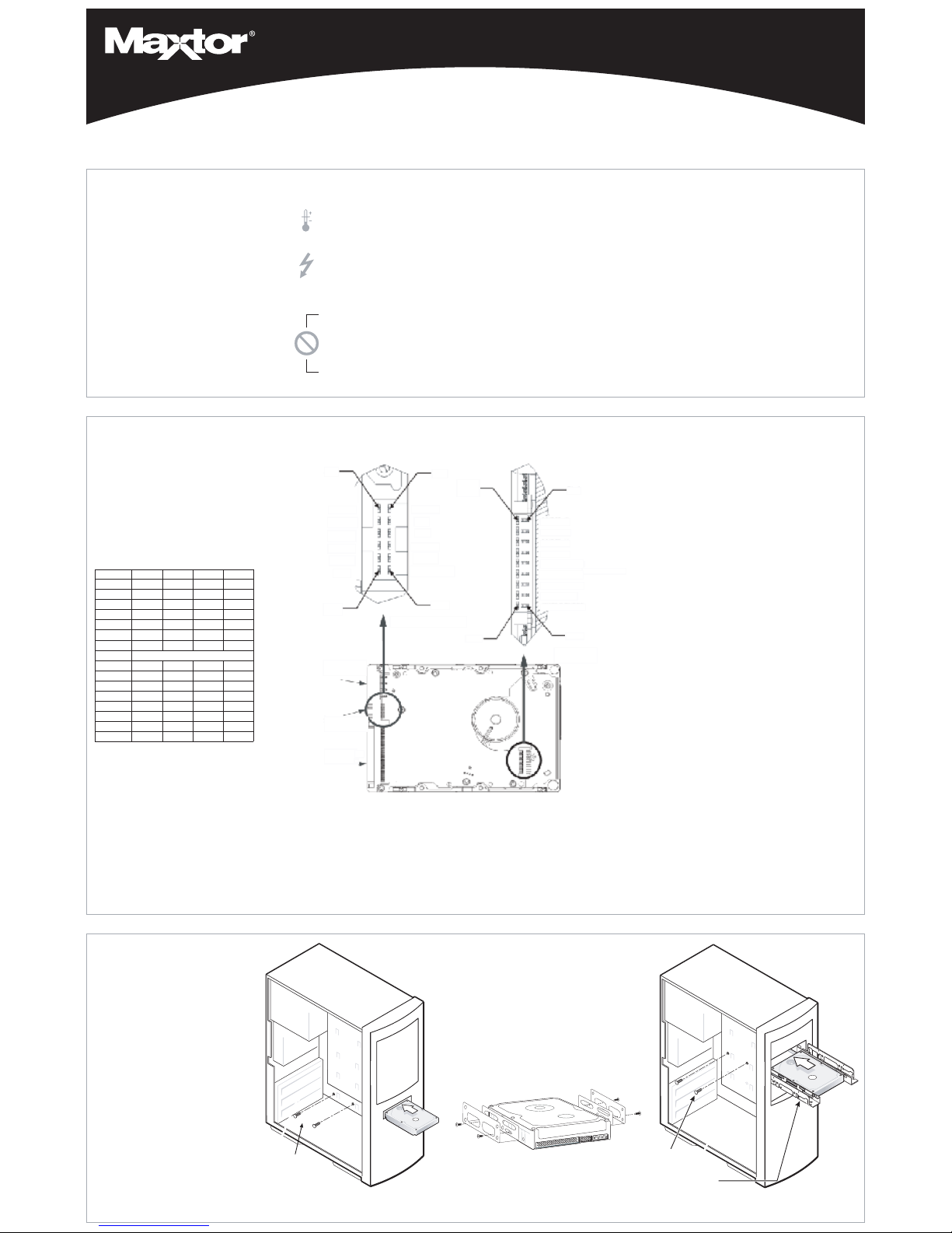
Configure the Drive Jumpers
If spec ific jumpe r options are ne eded
for your s ystem configuration, ref er to
the illus trations and definitions provided
in this se ction.
SCSI ID Jumper Settings
M axtor S CS I drives typically ship from
the factory w ith jumpers set to S CSI
ID 6, a nd termination power jum ped.
S CSI ID 7 is usually rese rved for the
S CSI host adapter.
3
D rive
Install
Installing Drive Inside
of Y our Computer System
M ak e s ure y ou r co m pu ter
is pow ere d do w n befo re
ins tall ing th e dr iv e.
The follow ing illustrations are
of typical computer sys tems and
hard drive mounting s tyles .
Your com puter ma y have a different
mounting style. Pleas e re fer to your
compute r use r manual for more
informa tion.
B e s ure to s ecure the drive to the
device bay w ith all f our sc rews .
The drive should be oriented
with its printe d circuit board
facing down.
Installing 5.25-inch Mounting Brackets
If the hard drive will be installe d in a 5 .25inch de vice bay, attach mounting brack ets
(available separate ly) to the hard drive as
show n in the figure below.
Mounting Screws
Mounting Screws
Mounting Bracket
SC SI Hard Drive I nstallation Guide
N ote: M axtor LVD SC SI drives do not
support on-board termination. M axtor
recomme nds the use of Active LVD
terminators and 68-pin twis ted pair
cabling.
SCS I hos t adapter manufa cture rs
usua lly s upply proper c abling and
termination w ith the purc hase of an
LVD SCS I hos t adapter.
At ten tion : T he R ear J umper O ption
Conne ctor is an OEM spec ific connector. M ost ins tallations w ill never
use the jum per options on this
connector. Alw ays configure the
drive using the jumpers at the Fr ont
J umper O ption Co nnect or.
Other Jumper Settings
TP - T ermi natio n P owe r (1 2 P in O ption Co nnect or)
Pins 11-12 T erm ination powe r ens ures that the re is a s ufficient
power level a long the e ntire S CSI bus. It is recom mended
that the final devic e on the SC SI bus hav e the Termination
Pow er jumper installed. All de vices in betw een the host and
final dev ice typica lly have no jumper on Termination P ower.
Note that Termination Powe r is not the s ame as o n-board
termination, whic h this drive does not s upport.
S S - S tag ger S pin
Pins 13-14 For m ost c onfigurations this option is not utilized.
Mos t cur rent S CSI host adapters offer a S tart Unit command
enable or disable, w hich supe rsede s the functionality of the
SS jumpe r se tting. W hen the Delay Spin (D S) jum per is
enabled on the drive , the Start Unit c ommand f rom the SC SI
host adapter w ill sen d Start Unit co mmands to all de vices on
the bus at pre -determined intervals. This can help preve nt
power supply overload w hen running s evera l device s on the
SC SI bus.
W P - W rite Pr otect ion
Pins 11-12 B y factory default, the drive is shipped w ith no
jumper on these pins, and the drive ca n be w ritten to u nless
protecte d by application softw are. With the pins jumped, the
drive c an be us ed a s a read-only devic e. T his f eature prevents
accide ntal overw rites and is u seful for fre quently acc ess ed
archives and re ferenc e files .
For ce S E Ð F orce S ingle En ded Op erat ion
Pins 17 -18 B y fac tory default, the drive is shipped with no
jumper on thes e pins. W ith mos t sy stem configurations , it is
not nec ess ary to use this jum per. LVD drives are mu lti-mode
capable. They will auto matically de tect the pres ence of a s ingle-ended bus and revert to single-e nded mode .
DS - De lay S pin
Dis able D elay S pin: No jumper a cross pins 15-16 (f actory
default). Disa bling Delay Spin allow s the drive to spin up
whe n the s yste m is powere d up.
En able D elay S pin: J umper across pins 15-16 This setting
will pre vent the drive f rom s pinning up until it receive s a Start
Unit c ommand f rom a SCS I hos t adapter. Mos t SC SI host
adapters have the S tart Unit command enabled by default in
the hos t adapte r BI OS . E nabling Delay Spin is only nece ssa ry
whe n you are starting multiple dev ices at powe r on.
S CS I ID
Pin num bers 1-8 are typically re ferred to in pairs as A0 (pins 1
and 2), A1 (3,4), A2 (5,6), A3 (7,8). The jumper pairs will allow
configuration of S CS I ID' s 0 to 1 5. A ll SC SI devices mus t have
an individual I D on the SC SI bus (there is no M aste r/Slave setting). S CS I ID 7 is us ually res erved for the SC SI ho st adapte r.
Fau lt LE D a nd Bu sy O ut J umpe rs
Typical ins tallations do not require the use of the Fault L ED
and B usy Out jum pers. The Bus y O ut signal is us ually s upplied
through the PCI bus to the PC motherboard' s B usy indicator
LE D. If co nnecting the Bus y O ut jumper for a drive ins talled in
an ex ternal ca se, pleas e ref er to the wiring documentat ion supplied by the manuf acturer of the case . C onnection o f the Fault
LE D is not re comme nded in inte rnal or ex ternal ins tallations.
Computer with available
3.5-inch device bay
Computer with available
5.25-inch devic e bay
DIevirDOtiBDI1tiBDI2tiBD tiBDI
0DIFFOFFOFF FO
1DINOFFOFF FO
2DIFFONOFF FO
3DINONOFF FO
4DIFFOFFONFO
5DINOFFONFO
6DIFFONONFO
7DITSOHISCSROFDEVRESER
8DIFFOFFOFFONO
9DINOFFOFFONO
01DIFFONOFFONO
11DINONOFFONO
21DIFFOFFONONO
31DINOFFONONO
41DIFFONONONO
51DINONONONO
Pin 2
Pin 1
Pin 17
Pin 18
SCSI ID 3
SCSI ID 2
SCSI ID 1
SCSI ID 0
BUSY LED
-/+
WRT PROTECT
STAGGER SPIN
DELAY SPIN
SINGLE ENDED
FAULT LED
GROUND
GROUND
BUSY LED
GROUND
TERM POWER
SCSI ID 3
SCSI ID 2
SCSI ID 1
SCSI ID 0
NOT USED
+5 V
Pin 1
Pin 2
Pin 11
Pin 12
4 Pin Power
Connector
12 Pin Option
Connector
68 Pin SCSI
Connector
Page 2
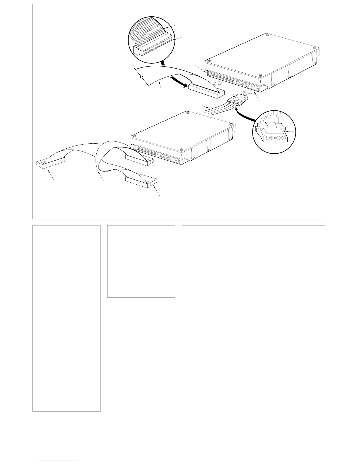
Pin 1
68-pin Connector
68-pin Drive
Connector
DC Power
Connector
Ultra LVD/SE Cable
Power Supply Cable
(3-Pin or 4-Pin)
Bevel
4
Cable
Hook-up
Attach the SCSI and Power Cables
If the M axtor S CS I drive is the only de vice attached to
the SCS I adapter c ard, atta ch the drive at the end of the
Ultra LV D /S E c able, f arthest from the S CSI adapter
card. This connec tor has a beve led edge and will only
fit one way. Then attach an externa l active LVD /S E SC SI
term inator.
Ple ase refer to the S CS I adapte r card us er guide
for additional recomm endations on data c able placement and S CSI te rmination requireme nts.
Attac h a pow er cable to the power connector on the
hard drive . This conne ctor is keye d and w ill
only f it one w ay. C heck all other c able conne ctions
before you turn on the computer.
Ca uti on: D o not for ce or rock the c onnectors into their
soc kets on the hard drive. Pus h them in straight until
they are s eated firmly.
5
P a r t it io n in g
F o r m a t t i n g
M axtor hard drives can ac cept ne arly all
operating sys tems . S ome operating s ystems have volume size limitations that
may require you to partition your drive
into m ultiple volumes . Pleas e re fer to
your s ys tem or SC SI adapter card us er
guide f or informa tion about for matting
and partitioning the drive.
General Guideli nes
¥ D OS /W ind ow s 9 X/ ME :
Us e F DIS K.E XE to partition and
FO RM AT.CO M to form at the drive.
¥ W in dow s N T/ 2000:
B oot your s ys tem f rom the installation floppy disks provided with the
OS to partition and form at the drive.
If you do not have the original ins tallation floppie s, you can create them
using your W indows ins tallation CD .
¥ W in dow s X P:
B oot your s ys tem f rom the Window s
XP installation CD to partition and format the drive. If your s yste m is not
capable of booting from a CD, you
can download bootable W indows XP
installation floppies from Micros oft' s
we bsite at ww w.m icrosof t.com
¥ M ac int os h: M ost non-Apple branded
hard drive s c an be formatted using
the Drive S etup utility included in Mac
OS 8. 6 and above. Mac OS ve rsions
before 8. 6 will require a third-party
hard drive utility s uch as F WB H ard
Dis k Toolkit (w ww. fwb. com) or Intec h
Hard Disk Spe edTools
(ww w.inte chusa. com) to partition and
initialize the drive. Ple ase visit the
FW B or Inte ch w ebsite for details on
thes e non-M axtor softw are produc ts.
www.maxtor.com
6
P r o d u c t
R e g ist r a t io n
Take Advantage of the Benefits!
B y regis tering your new Max tor product, yo ull have the option to re ceive
product updates , s pecial of fers, and
other valuable inform ation about othe r
data s torage solutions from M axtor.
S imply point your w eb brows er to:
w ww .m ax tor.c om go to the
product regis tration page, and complete the s hort ques tionnaire.
Change s are periodically made t o the info rmation here in Ð w hich w ill be incor porated in re vised editions of
the public ation. M axtor m ay mak e change s or improveme nts in the product(s ) des cribed in this publication
at any time and without notice.
Copyright © 2 001 Maxtor Corporation. All rights res erved. Printed in the U .S .A. 12/01. Max tor¨is a regis tered trademark of M axtor C orporation. Other bra nds or products are tradem arks or regis tered tra demarks
of their respective holders.
Active LVD
Terminator
Connect to
SCSI Host
Adapter
Card
Ultra
LVD/SE
Cable
Standard Cabling for S ingle SCSI Drive in System
(Ultra LVD/ SE cable connections)
Cable Connections for SCSI Drive
 Loading...