

Page 1
Application Note:
Interfacing non-standard cameras to Matrox Pulsar
DALSA CL-C8-6000A November 26, 1996
Camera
Interface
Overview
Camera
Interface
Details
• 6000 pixels (3000 x 2 x 8-bit)
• Variable line scan rate
• Digital video output (RS-422)
• Exposure control
• 2 modes of operation: variable line scan rate, programmable line scan rate
(with programmable exposure control)
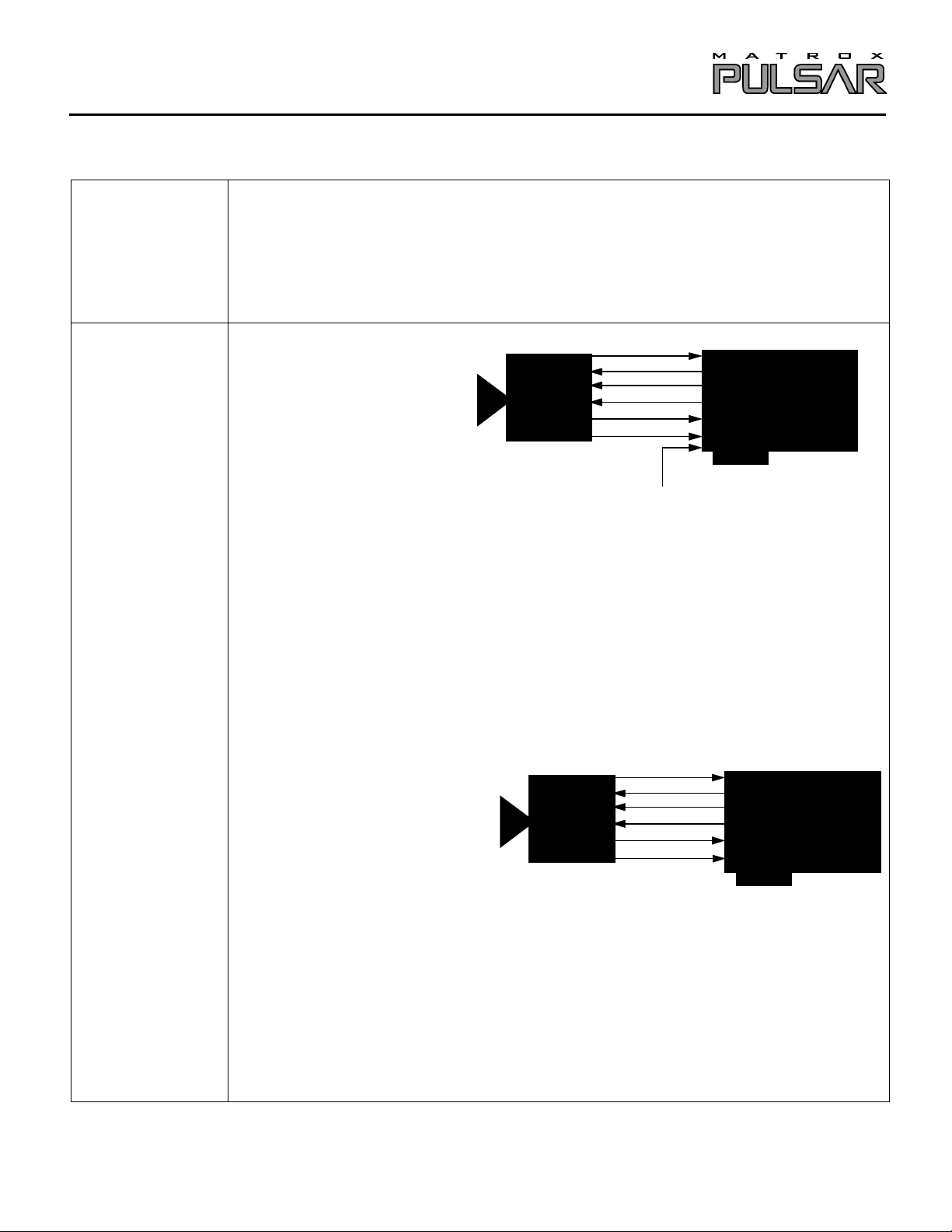
Mode 1: Variable line scan rate
Dalsa
Cl-C86000A
• 2988 x 2 x 8-bit
• Digital video output (RS-422)
• DCF configured for 480 lines per virtual frame
• Line scan rate is variable and is controlled by external trigger signal
• Matrox Pulsar receiving TTL external trigger
• Matrox Pulsar sending RS-422 EXPOSURE 1 (PRIN), EXPOSURE 2 (EXSYNC) and RS-
Video
PRIN
EXSYNC
MCLK
LVAL
STROBE
TTL external trigger
(with PULSAR/DIG/MOD)
Matrox Pulsar
422 reference clock (MCLK) signals to camera; the EXPOSURE2 signal initiates line
readout
• Matrox Pulsar receiving RS-422 pixel clock (STROBE @ 15 MHz) and RS-422 hsync
(LVAL) signals from camera
• Exposure control can be changed via INTELLICAM or MIL digitizer control functions.
• DCFs used: CLC8DAL.DCF
PUL-CID-032
Mode 2: Programmable line scan rate (with programmable exposure control)
Video
Dalsa
Cl-C86000A
• 2988 x 2 x 8-bit
• Digital video output (RS-422)
• DCF configured for 480 lines per virtual frame
• Matrox Pulsar sending EXPOSURE 1 (PRIN), RS-422 EXPOSURE2 (EXSYNC) and RS-
PRIN
EXSYNC
MCLK
LVAL
STROBE
Matrox Pulsar
(with PULSAR/DIG/MOD)
422 reference clock (MCLK) signals to camera; the EXPOSURE2 signal initiates line
readout
• Matrox Pulsar receiving RS-422 pixel clock (STROBE @ 15 MHz) and RS-422 hsync
(LVAL) signals from camera
• Line scan rate and exposure control and can be changed via INTELLICAM or MIL digitizer
control functions.
• DCFs used: CLC8DEL.DCF
Page 2

Application Note:
Interfacing non-standard cameras to Matrox Pulsar
DALSA CL-C8-6000A November 26, 1996
Cabling
Requirements
Mode 1: Variable line scan rate
• IMG-7W2-TO-5BNC cable required for TTL external trigger source and
PULSAR/DIG/MOD required for digital data, syncs and control signals in RS-422 format
• TTL external trigger source should be connected to the TTL Trigger Input of the IMG-7W2-
TO-5BNC cable
• The connections between the 20-pin dual row connector (labeled OS1 and OS2) of the
camera and the 68-pin SCSI-2 connector of the PULSAR/DIG/MOD are as follows:
DALSA CL-C8-6000A PULSAR/DIG/MOD
(20-pin dual row connector - OS1) (PULSAR/CBL/OPEN connector)
Pin name Pin no. Pin name Pin no.
AD7+ 1 → DATA7+ 10
AD7- 2 → DATA7- 44
AD6+ 3 → DATA6+ 11
AD6- 4 → DATA6- 45
AD5+ 5 → DATA5+ 13
AD5- 6 → DATA5- 47
AD4+ 7 → DATA4+ 14
AD4- 8 → DATA4- 48
AD3+ 9 → DATA3+ 15
AD3- 10 → DATA3- 49
AD2+ 11 → DATA2+ 16
AD2- 12 → DATA2- 50
AD1+ 13 → DATA1+ 19
AD1- 14 → DATA1- 53
AD0+ 15 → DATA0+ 20
AD0- 16 → DATA0- 54
STROBE+ 17 → CLKIN+ 29
STROBE- 18 → CLKIN- 63
LVAL+ 19 → HSYNC+ 26
LVAL- 20 → HYSNC- 60
DALSA CL-C8-6000A PULSAR/DIG/MOD
(20-pin dual row connector - OS2) (PLS/CBL/OPEN connector)
Pin name Pin no. Pin name Pin no.
BD7+ 1 → DATA15+ 2
BD7- 2 → DATA15- 36
BD6+ 3 → DATA14+ 3
BD6- 4 → DATA14- 37
BD5+ 5 → DATA13+ 4
BD5- 6 → DATA13- 38
BD4+ 7 → DATA12+ 5
BD4- 8 → DATA12- 39
BD3+ 9 → DATA11+ 6
BD3- 10 → DATA11- 40
BD2+ 11 → DATA10+ 7
BD2- 12 → DATA10- 41
BD1+ 13 → DATA9+ 8
(Pin-out continued)
PUL-CID-032 2
Page 3
Application Note:
Interfacing non-standard cameras to Matrox Pulsar
DALSA CL-C8-6000A November 26, 1996
BD1- 14 → DATA9- 42
BD0+ 15 → DATA8+ 9
BD0- 16 → DATA8- 43
not connected 17
not connected 18
not connected 19
not connected 20
• The connections between the DB-25 connector on the rear panel of the camera and the 68-pin
SCSI-2 connector of the PULSAR/DIG/MOD are as follows:
DALSA CL-C8-6000A PULSAR/DIG/MOD
(DB-25 male connector) (PLS/CBL/OPEN connector)
Pin name Pin no. Pin name Pin no.
MCLK+ 6 ← CLKOUT+ 24
MCLK- 19 ← CLKOUT- 58
EXSYNC+ 17 ← EXPOSURE2+ 28
EXSYNC- 4 ← EXPOSURE2- 62
PRIN+ 5 ← EXPOSURE1+ 30
PRIN- 18 ← EXPOSURE1- 64
GROUND 7 GROUND 1
GROUND 11 GROUND 12
GROUND 20 GROUND 34
GROUND 24 GROUND 35
Power Supply PLS/CBL/OPEN
GROUND GROUND 46
GROUND GROUND 68
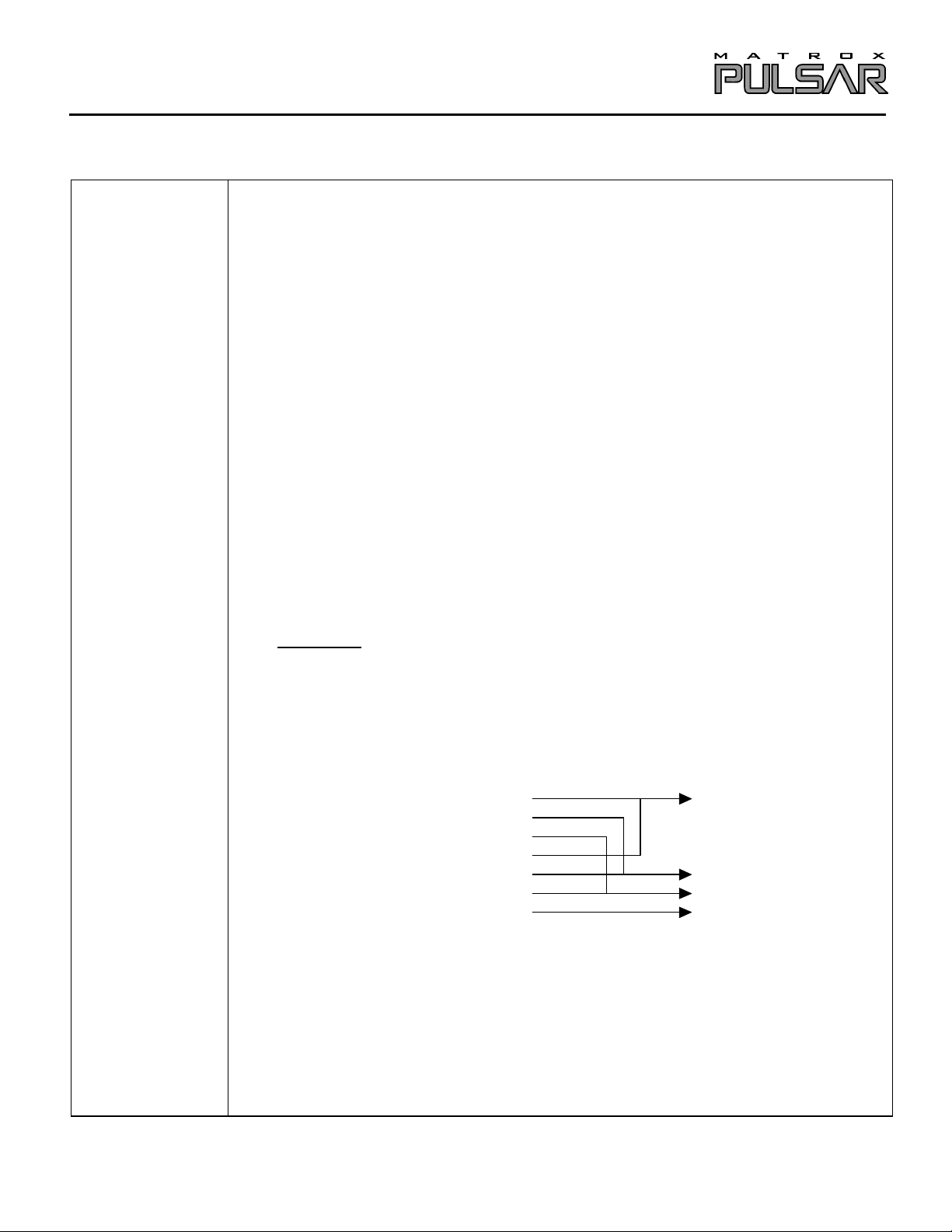
• The connections between the DB-25 connector on the rear panel of the camera and the power
supply are as follows:
Dalsa CL-C8-6000A
(DB-25 male connector) POWER SUPPLY
Pin no. Pin name
8
9
12
13
21
22
25
+
+
−
+
+
−
−
5V
15V
5V
5V
15V
5V
15V
+
+
−
−
5V
15V
5V
15V
NOTE: it is very important that all the GROUNDs of the camera be connected together to the
POWER SUPPLY GROUND, which in turn must be connected to the GROUND of
the Pulsar
Mode 2: Programmable periodic line scan rate (programmable exposure control)
• All connections except IMG-7W2-TO-5BNC cable (no TTL external trigger) are as in Mode
1: variable line scan rate
PUL-CID-032 3
Page 4
Application Note:
The time between the arrival of the rising edge of EXPOSURE1 and the rising edge of
that control the width and the deployment time of each of the EXPOSURE1 and
EXPOSURE2 pulses must be set in the DCF at the hardware register level. A hardware
register editor is provided by running Intellicam with the -hwreg option (specifically by
running INTELCAM -hwreg). An additional menu item, “HW REGISTER EDITOR”,
appears on the main menu screen. The following registers are used to define the exposure
The above are 16-bit registers that have been split in two: the low byte and the high byte.
the Pulsar. CTRL_SET1CNT controls the amount of time that is set on the timer for
EXPOSURE1 (timer1); the timer starts at this value and counts down to zero.
the EXPOSURE1 pulse is sent. When timer1 reaches the value set for CTRL_T1START,
The EXPOSURE1 signal should be sent immediately to the camera upon arrival of an
external trigger signal to indicate that exposure should begin, therefore CTRL_SET1CNT
and CTRL_T1START must be set equal to each other; this is accomplished by setting
CTRL_SET1CNTL equal to CTRL_T1STARTL and CTRL_SET1CNTH equal to
CCD charge (3ms)
Interfacing non-standard cameras to Matrox Pulsar
DALSA CL-C8-6000A November 26, 1996
Special
Considerations
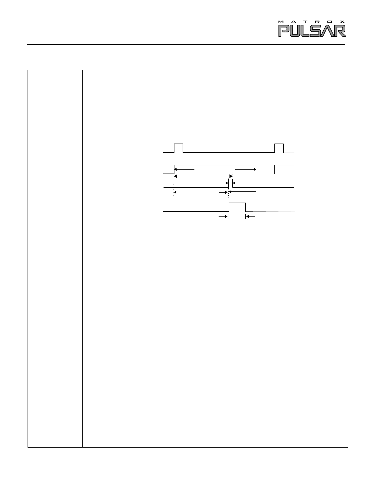
Mode 1: Variable line scan rate
• The line scan rate is variable and is controlled by the external trigger signal.
• Once it has received the external signal to trigger, the Pulsar sends the RS-422 EXPOSURE1
(PRIN) signal to the camera to initiate exposure. The Pulsar will send the RS-422
EXPOSURE2 (EXSYNC) signal to the camera following a delay that is equal to the desired
exposure time.
•
TTL external trigger
EXPOSURE1 (PRIN)
EXPOSURE2 (EXSYNC)
HSYNC (LVAL)
2.7ms
exposure time start of video
200µs
34µs
video valid
EXPOSURE2 signals is the exposure time. In order to select the exposure time, the registers
timings:
EXPOSURE1: CTRL_SET1CNTL EXPOSURE2: CTRL_SET2CNTL
CTRL_SET1CNTH CTRL_SET2CNTH
CTRL_T1STARTL CTRL_T2STARTL
CTRL_T1STARTH CTRL_T2STARTH
Here, the timer for the EXPOSURE1 start as soon as the external trigger signal is received by
CTRL_T1START is the width of the EXPOSURE1 pulse and also controls the time at which
the EXPOSURE1 signal being sent to the camera goes high. When timer1 reaches zero, the
EXPOSURE1 signal goes low.
CTRL_T1STARTH.
PUL-CID-032 4
Page 5

Application Note:
The Pulsar indicates to the camera that exposure should stop by sending the EXPOSURE2
pulse. For a given setting of CTRL_SET2CNT, which is the time set on the timer for
EXPOSURE2 (timer2), the time at which the EXPOSURE2 pulse is sent is controlled by
signal being sent to the camera goes high. When timer2 reaches zero, the EXPOSURE2
Finally, it should be noted that the EXPOSURE1 pulse must remain high until the LVAL
The maximum possible delay between the EXPOSURE2 pulse and the LVAL pulse is
calculated to be 6.4µs (4µs + 11 MCLK + 4 MCLK + 400ns or 4µs + 0.73µs + 0.26µs +
400ns = 5.39µs maximum). The line transfer time is 199.9µs (2988 pixels times at a clock
Interfacing non-standard cameras to Matrox Pulsar
DALSA CL-C8-6000A November 26, 1996
CTRL_T2START, the width of the EXPOSURE2 pulse. Timer2 starts counting down from
CTRL_SET2CNT; when it reaches the value set for CTRL_T2START, the EXPOSURE2
signal goes low.
pulse goes low. Therefore, the time set on timer1 (CTRL_SET1CNT) must be greater than
the sum of the exposure time, the maximum possible delay between the EXPOSURE2 pulse
and the LVAL pulse, and the width of the LVAL pulse (the line transfer time).
rate of 15 MHz).
So to summarize:
CTRL_T1START = CTRL_SET1CNT, i.e., CTRL_T1STARTL = CTRL_SET1CNTL
and CTRL_T1STARTH = CTRL_SET1CNTH
EXPOSURE TIME = CTRL_SET2CNT -CTRL_T2START
CTRL_SET1CNT > exposure time + maximum delay between EXPOSURE2 and LVAL
pulses (5.39µs) + line transfer time (199.9µs)
Remember that each 16-bit register is split into a low and high byte. These values must be in
pixels and must be set in hexadecimal; the value of each 16-bit register can vary between 0
(0000 in Hex) and 65 535 (FFFF in Hex). The registers are set in the following way:
T2 user clock 14.31MHz (clock source select)
Hex Decimal equivalent x user clock period
CTRL_ SET2CNTL DA 39130 x (69.9ns) = 2.7ms
CTRL_ SET2CNTH 98
CTRL_T2STARTL E8 488 x (69.9ns) = 34µs
CTRL_T2STARTH 1
T2=
2.7ms
PUL-CID-032 5
34µs
Page 6

Application Note:
Interfacing non-standard cameras to Matrox Pulsar
DALSA CL-C8-6000A November 26, 1996
T1 user clock 14.31MHz (clock source select)
Hex Decimal equivalent x user clock period
CTRL_ SET1CNTL CA 42954 x (69.9ns) = 3 ms
CTRL_ SET1CNTH A7
CTRL_T1STARTL CA 42954 x (69.9ns) = 3 ms
CTRL_T1STARTH A7
T1=
3 ms
When computing the hardware registers, the following question may be asked: “Some
registers have been manually edited. OK to overwrite them all? (y/n)”. Answer “no” to this
question and to all questions that follow.
IMPORTANT! These instructions must be followed very carefully; the only registers that
should be modified are those mentioned above. Please consult Matrox Imaging Applications at
(514) 822-6061 if assistance is required.
• The default exposure time for this DCF is 2.7 ms
• For this DCF, the minimum line scan rate is 3.1ms. The line scan rate can be increased by
changing the RS-422 external trigger (for this DCF, the period of the external trigger can be
equal to or more than 3.1 ms).
• Use Matrox Intellicam in order to modify the DCF for RS-422 external trigger input. Consult the
Matrox Intellicam User Guide for more information.
• Contact your local sales representative or Matrox Sales Office, or contact Matrox Imaging
Applications at 514-822-6061 for assistance (if required).
Mode 2: Programmable line scan rate (with programmable exposure control)
• The time between the arrival of the rising edge of EXPOSURE1 and rising edge of
EXPOSURE2 signals is the exposure time. In order to select the exposure time, the registers
that control the width and the deployment time of each of the EXPOSURE1 and EXPOSURE2
pulses must be set in the DCF at the hardware register level or by programming the line scan
rate for this DCF. A line scan rate programmed higher than the default will cause no problem,
to an upper limit of approximately 4.8KHz.
• The default line scan rate is 3.1 ms (322 Hz).
• The default exposure time for this DCF is 2.7 ms
• Remember that each 16-bit register is split into a low and high byte. These values must be in
pixels and must be set in hexadecimal; the value of each 16-bit register can vary between 0 (0000
in Hex) and 65 535 (FFFF in Hex). The registers are set in the following way : (continued next
page)
PUL-CID-032 6
Page 7

Application Note:
DA98 → count down → 1E8 0
CCD charge
Interfacing non-standard cameras to Matrox Pulsar
DALSA CL-C8-6000A November 26, 1996
T2 user clock 14.31MHz (clock source select)
Hex Decimal equivalent x user clock period
CTRL_ SET2CNTL DA 39130 x (69.9ns) = 2.7ms
CTRL_ SET2CNTH 98
CTRL_T2STARTL E8 488 x (69.9ns) = 34µs
CTRL_T2STARTH 1
34µs
T2=
2.7ms
T1 user clock 14.31MHz (clock source select)
Hex Decimal equivilant x user clock period
CTRL_ SET1CNTL 5D 44381 x (69.9ns) = 3.1 ms
CTRL_ SET1CNTH AD
CTRL_T1STARTL CA 42954 x (69.9ns) = 3 ms
CTRL_T1STARTH A7
T1=
3.1 ms
AD5D
EXPOSURE1 (PRIN)
EXPOSURE2 (EXSYNC)
HSYNC (LVAL)
The DCF(s) mentioned in this application note can be found on the MIL and MIL-Lite CD, or our FTP site (ftp.matrox.com). The information furnished by
Matrox Electronics System, Ltd. is believed to be accurate and reliable. Please verify all interface connections with camera documentation or manual.
Contact your local sales representative or Matrox Sales office or Matrox Imaging Applications at 514-822-6061 for assistance.
CorporateCorporate
Headquarters:Headquarters:
Canada and U.S.A.Canada and U.S.A.
Matrox ElectronicMatrox Electronic
Systems Ltd.Systems Ltd.
1055 St.Regis Blvd.
Dorval, Quebec, Canada
H9P 2T4
Tel: (514) 685-7230
Fax: (514) 822-6273
Sales Offices:Sales Offices:
U.K.U.K.
Matrox (UK) Ltd.Matrox (UK) Ltd.
Sefton Park, Stoke Poges
Buckinghamshire
U.K. SL2 4JS
Tel: +44 (0) 1753 665500
Fax: +44 (0) 1753
665599
FranceFrance
Matrox France SARLMatrox France SARL
2, rue de la Couture,
Silic 225
94528 Rungis Cedex
Tel: (0) 1 45-60-62-00
Fax: (0) 1 45-60-62-05
A7CA
exposure time
GermanyGermany
Matrox GmbHMatrox GmbH
Inselkammerstr.8
D-82008
Unterhaching
Germany
Tel: 089/614 4740
Fax: 089/614 9743
0
start of video
video valid
Asia PacificAsia Pacific
Matrox Asia LiaisonMatrox Asia Liaison
OfficeOffice
Rm. 1901, 19/F, Workington
Tower,
78 Bonham Strand E.,
Sheung Wan, Hong Kong.
Tel: 852.2877.5387
Fax: 852.2537.9530
PUL-CID-032 7
 Loading...