

Page 1
MATROX CORONA-II
CAMERA INTERFACE APPLICATION NOTE
SONY XC-EI30/50, ES30/50 OCTOBER 15, 2001
Basics about the
camera
Mode of operations as
per Matrox Imaging (in
parentheses as per
camera manufacturer)
Basics about the
interface modes
Camera Descriptions
§ 754 × 484 @ up to 60 fps.
§ Single channel analog video output.
§ Interlaced or progressive scan.
§ Internal or external sync.
§ Internal or external exposure control.
§ 15.734 MHz pixel clock rate.
Interface Modes
§ Continuous
§ Asynchronous reset (Restart/Reset mode)
Camera Interface Briefs
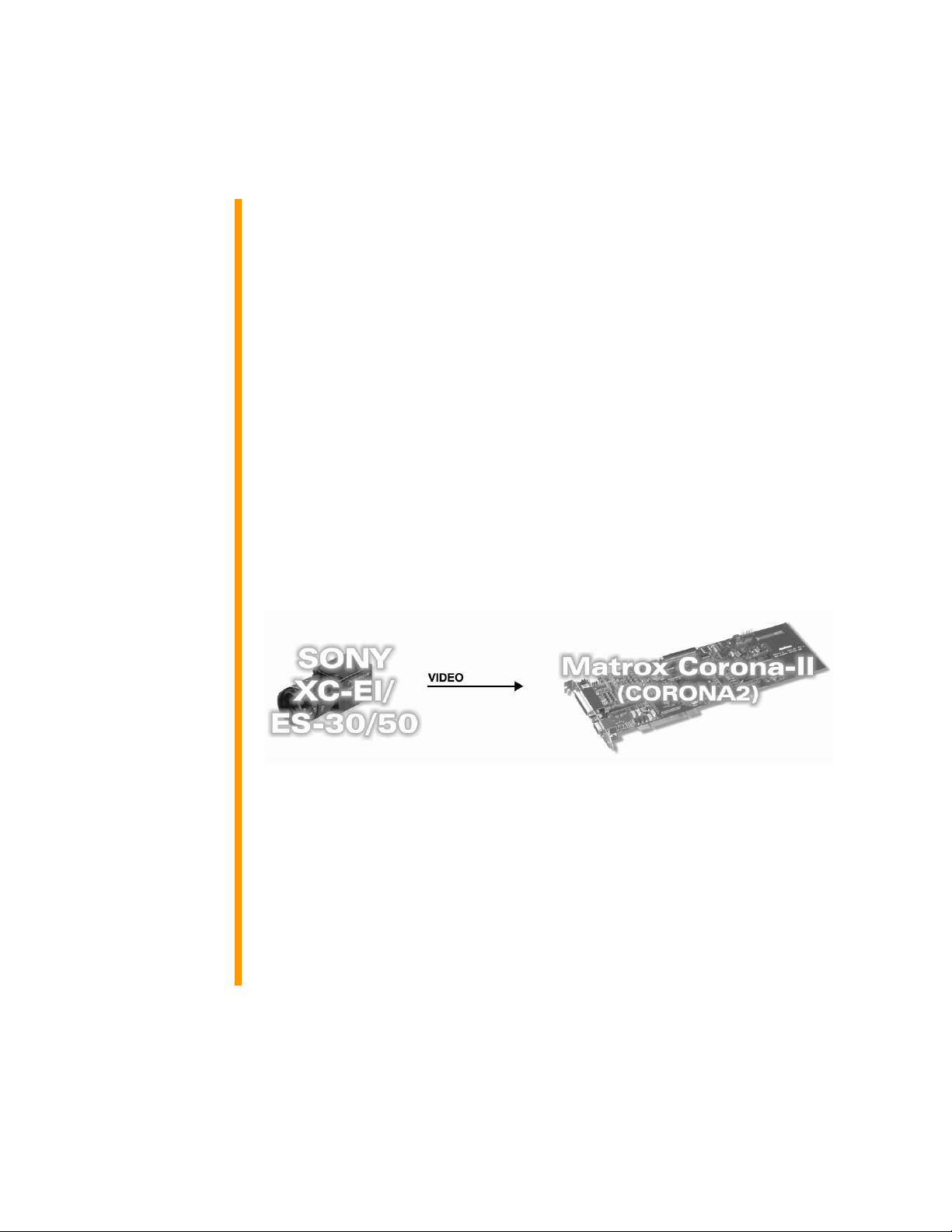
Mode 1: Continuous
§ 754 × 484 × 8-bit @ 30 fps.
§ Single channel analog video.
§ Interlaced scan.
§ Matrox Corona-II receiving video signal (composite sync) from camera.
§ DCF used: XC3050C.DCF
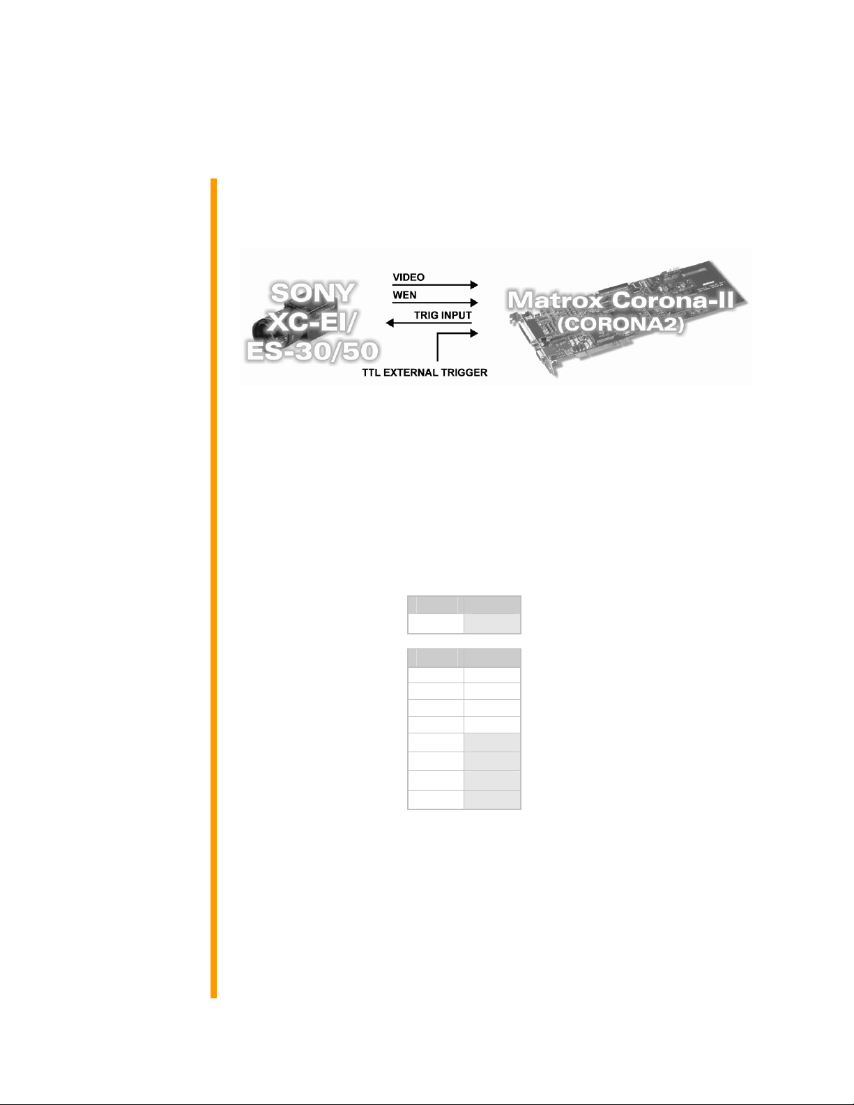
Mode 2: Asynchronous Reset (Restart/Reset mode)
§ 754 × 242 × 8-bit @ up to 60 fps.
§ Single channel analog video.
§ Progressive scan.
§ Matrox Corona-II receiving external trigger signal.
§ Matrox Corona-II sending EXPOSURE1 (EXT. TRIG IN) signal to camera
to initiate and control exposure time.
§ Matrox Corona-II receiving video signal (composite sync) from camera.
Continued…
COR2-CID-003 1
Page 2
MATROX CORONA-II
CAMERA INTERFACE APPLICATION NOTE
SONY XC-EI30/50, ES30/50 OCTOBER 15, 2001
Basics about the
interface modes
Camera Interface Briefs (Continued)
Mode 2: Asynchronous Reset (Restart/Reset mode)
§ DCF used: 3050AEN.DCF
Specifics about the
interface modes
Camera Interface Details
Mode 1: Continuous
§ Frame Rate: Matrox Corona-II receives the continuous video from the
camera at 30 frames per second.
§ Exposure time: Exposure time is inversely proportionate to the frame
rate (no shutter) or determined by the shutter setting. Refer to the camera
manual for more information.
§ Camera Switch settings: Internal/External synchronization switch and
DIP switches are set as follows, refer to the camera manual for additional
information:
EXT INT
Internal/External Sync
ON OFF
Shutter Speed 1 * *
Shutter Speed 2 * *
Shutter Speed 3 * *
Shutter Speed 4 * *
Field/ Frame/ 5
Mode 6
Mode 7
Mode 8
* Shutter switches are not effective in this mode
ü
ü
ü
ü
ü
Mode 2: Asynchronous Reset (Restart/Reset mode)
§ Frame rate: The frame rate is determined by the frequency of the
external trigger signal, up to a maximum of 30 fps.
§ Exposure time: The width (rising edge to falling edge) of the
EXPOSURE1 (EXT. TRIG IN) signal plus a fixed internal camera delay of
1H to 2H equals the exposure time. The exposure time can be modified in
the DCF using Matrox Intellicam or with the MIL digitizer control function
MdigControl(). Refer to the appropriate manual or user guide for more
information.
COR2-CID-003 2
Page 3

MATROX CORONA-II
CAMERA INTERFACE APPLICATION NOTE
SONY XC-EI30/50, ES30/50 OCTOBER 15, 2001
Specifics about the
interface modes
Cabling details for this
interface mode
Pin name Pin no. Pin name Pin no.
Camera Interface Details (continued)
Mode 2: Asynchronous Reset (Restart/Reset mode)
§ Timing diagram:
§ Camera Switch settings: Internal/External synchronization switch and
DIP switches are set as follows, refer to the camera manual for additional
information:
EXT INT
Internal/External Sync
ON OFF
Shutter Speed 1 * *
Shutter Speed 2 * *
Shutter Speed 3 * *
Shutter Speed 4 * *
Field/ Frame/ 5
Mode 6
Mode 7
Mode 8
* Shutter switches are not effective in this mode
ü
ü
ü
ü
ü
Cabling Requirements
Mode 1: Continuous
§ Cable: DBHD44-TO-8BNC/O (open ended) cable required for video,
synchronization and control signals.
§ Connection: Connections between the 12-pin connector of the camera
and the 44-pin connectors of the Matrox Corona-II are as follows:
CORONA2
(44-pin connector)
VID1_IN 15
GROUND 17 -- GROUND 03
←
SONY XC-ST70/ST50/ST30
(12-pin connector)
VIDEO OUTPUT 04
COR2-CID-003 3
Page 4

MATROX CORONA-II
CAMERA INTERFACE APPLICATION NOTE
SONY XC-EI30/50, ES30/50 OCTOBER 15, 2001
Cabling Requirements (continued)
Mode 2: Asynchronous Reset (Restart/Reset mode)
§ Cable: DBHD44-TO-8BNC/O (open ended) cable required for video,
synchronization and control signals.
§ External trigger: TTL external trigger signal connected to the
OptoCoupled Trigger input (pin 34, 35) of the DBHD44-TO-8BNC/O
cable.
§ Connection: Connections between the 12-pin connector of the camera
and the 44-pin connectors of the Matrox Corona-II are as follows:
CORONA2
(44-pin connector)
Pin name Pin no. Pin name Pin no.
VID1_IN 15
EXPOSURE1 38
GROUND 17 -- GROUND 03
OPTOTRIG + 35
OPTOTRIG - 34
§ Power supply: connections are as follows:
POWER SUPPLY
Pin name Pin no. Pin name Pin no.
DC OUT (+12 V) -- -- + 12 V 02
GROUND -- -- GROUND 01
←
→
←
←
SONY XC-ST70/ST50/ST30
(12-pin connector)
VIDEO OUT 04
EXT. TRIG IN 11
EXTERNAL TRIGGER SOURCE
BNC SIGNAL -BNC GROUND --
SONY XC-ST70/ST50/ST30
(12-pin connector)
The DCF(s) mentioned in this application note can be found on the MIL CD or our FTP site (ftp.matrox.com). The information furnished by Matrox
Electronics System, Ltd. is believed to be accurate and reliable. Please verify all interface connections with camera documentation or manual. Contact
your local sales representative or Matrox Sales office or Matrox Imaging Applications at 514-822-6061 for assistance.
Corporate headquarters:
Canada and U.S.A.
Matrox Electronic Systems Ltd.
1055 St. Regis Blvd.
Dorval, Quebec H9P 2T4
Canada
Tel: (514) 685-2630
Fax: (514) 822-6273
COR2-CID-003
 Loading...